

Page 1
Verabar V200D (Double Rod)
1.0 SCOPE
These instructions provide procedures for installing the
V200 (Double Rod) Verabar flow sensor. Procedures are
given for all industrial flow measurement applications
including liquid, steam and gas service for both horizontal
and vertical piping configurations.
2.0 RECEIVING INSPECTION
The following tasks should be performed as part of the
receiving inspection procedure:
• Check items received against the packing list.
• Check sensor nameplate for proper model number,
serial number and customer number.
• Verify that the actual pipe diameter matches the ID
stated on the sensor nameplate.
• Check the bullet shaped sensor tube for any signs
of damage. Damage to the sensor tube may result
in erroneous flow readings.
• Check the round cover tube for any damage,
especially axial gouges or scratches. Damage to
the cover tube may prevent the packing from
sealing properly.
3.0 SAFETY PRECAUTIONS
Prior to installation of the Verabar flow sensor, check
maximum operating conditions on the flow sensor
nameplate and verify that they exceed the maximum
conditions of the installation. If any pressure,
temperature or flow limits will be exceeded, consult the
factory before proceeding.
INSTALLATION INSTRUCTIONS
4.0 INSTALLATION PREPARATIONS
4.1 Location
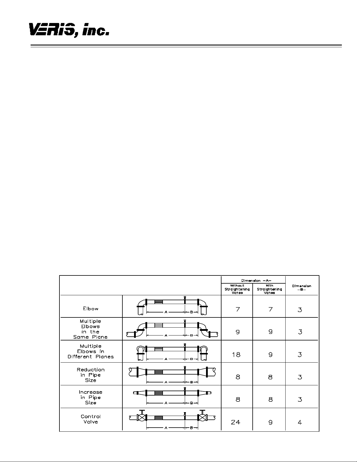
For the most accurate flow measurement, a minimum
straight run of pipe is required. Table 1 shows the
minimum straight run requirements. If longer straight
runs are available, position the Verabar such that the
ratio of upstream straight run to downstream straight run
is approximately 4 to 1. If straight run lengths are less
than the values stated in Table 1, consult the factory for
additional accuracy and location information. For
additional piping configurations, see Drawing SUB -4521.
Position straightening vanes such that the end closest to
the Verabar is half way between the Verabar and the
closest upstream configuration. For elbow installations,
mount the Verabar in the same plane as the closest
upstream elbow.
4.2 Orientation
Verify the proper sensor orientation by checking for an
“-H” (horizontal piping) or a “-V” (vertical piping) in the
model number on the Verabar name plate. Verify that
the flow arrow stamped on the instrument head is
pointing downstream in the direction of flow.
4.2.1 Horizontal Piping
For air or gas installations, mount the Verabar in the
upper 160° of the pipe to allow any condensate to drain
into the pipe (Figure 1). For liquid or steam installations,
mount the Verabar in the lower 160° of the pipe. This
allows any entrained air to bleed back into the pipe for
liquid applications and allows condensate to collect in
the instrument piping for steam applications.
Piping Configuration
Table 1. Straight Run Requirement s
Page 2
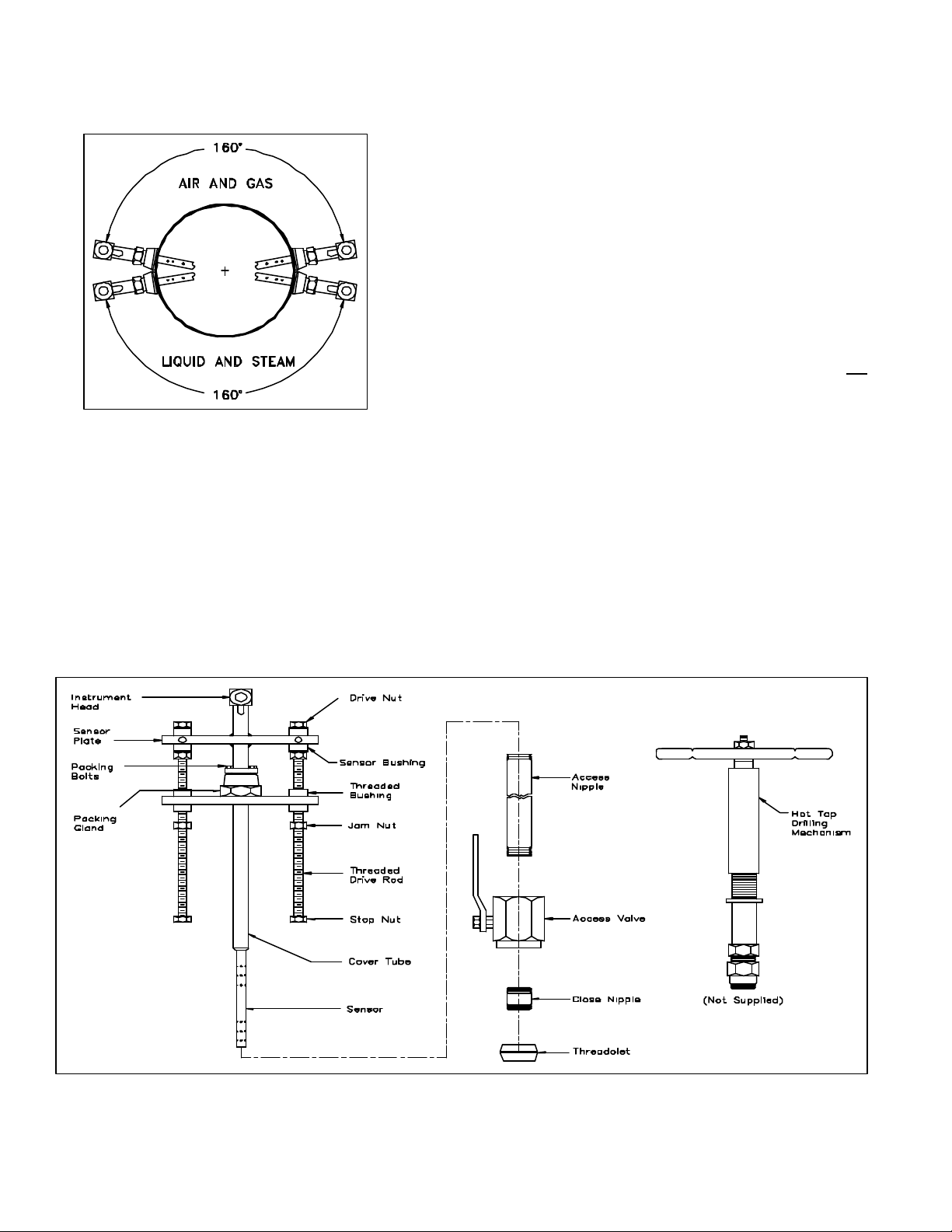
4.2.2 Vertical Piping
The Verabar may be mounted in any location around the
circumference of the pipe for vertical piping applications
(Figure 1).
Figure 1. Verabar Orientation in Horizontal Pipe
4.3 DP Transmitter/Local Indicator
Location
When choosing a Verabar location, consider the DP
transmitter/local indicator location:
• The transmitter must be mounted below the
Verabar for liquid and steam applications.
• The transmitter must be mounted above the
Verabar for air and gas applications.
4.4 Installation Drawings and Bill of
Materials
Additional information is available in the Installation
Drawings and Bill of Materials VB-7061 (also on the
VeraData CD). It contains standard and alternate
transmitter locations and a complete bill of materials
based on the fluid type and sensor orientation on the
pipe.
4.5 Piping Support
For sensors that extend more than 36” (915mm) beyond
the pipe wall or for sensors mounted in thin-walled pipes,
external support of the Verabar is recommended. This
will reduce stresses on the pipe wall.
5.0 INSTALLATION PROCEDURE
5.1 Assemble the Verabar
Your Verabar is shipped loosely assembled and is not
properly tightened for proper pressure retention. Follow
all assembly steps to ensure a safe installation (see
Figure 2).
5.2 Install Instrument Valves or Manifold
5.2.1 Valves
If the Verabar does not have a valve head, install
instrument valves using proper thread sealant. Be sure
instrument shut-off valves are installed and shut prior to
repressurizing the pipe.
5.2.2 Manifold
If the Verabar has a direct or integral manifold, be sure
the high and low pressure block valves are shut off prior
to repressurizing the pipe.
Figure 2. Verabar Model V200D (Double Rod)
Page 3

5.3 Install Access Nipple
Using proper sealant, thread access nipple into the
packing gland (Figure 3).
Cover
Tube
Figure 3. Access Nipple
5.4 Tighten Packing
Retract the Verabar such that the tip of the sensor is
flush with the end of the access nipple (Figure 3).
Tighten the three packing bolts on the packing gland.
5.5 Weld Threadolet to Pipe
Mark the location where the Verabar is to be mounted.
Position the threadolet over the center of the mark.
Using the appropriate weld gap, tack weld the threadolet
into position. Protect threads on the threadolet, then
finish welding the threadolet to the pipe per applicable
codes.
5.6 Install Close Nipple & Access Valve
Using the appropriate pipe thread sealant, install close
nipple and access valve. Orient the valve (Figure 4) such
that for horizontal pipes the valve handle is in-line
(perpendicular for vertical pipes) with the centerline of the
pipe. Be sure the valve handle does not hit the pipe
during opening and closing of the valve. Verify that the
close nipple and access valve are properly tightened,
because beyond this point, they will not be serviceable
without depressurizing the line.
Gap (1/16" [1.5mm] typical
Tack Weld
Protect Threads
Complete Weld
Access
Valve
Close
Nipple
Threadolet
• After the hole is completely drilled, retract the Hot
Tap Drilling Machine. Shut off the access valve
prior to removal of the Hot Tap Drilling Machine.
Figure 5. Hot Tap Drilling Machines
Note: There are numerous Hot Tap Drilling Machines on
the market with various pressure and temperature
ratings. These devices can usually be rented at a local
utility company. For more information concerning Hot
Tap Drilling Machines, the following companies can be
contacted: Mueller Co., Decatur, IL (217) 423-4471 or
T.D. Williamson Inc., Tulsa, OK (918) 446-1941.
5.8 Mount Sensor Assembly to Access
Valve
Apply appropriate thread sealant to the access nipple
and thread the access nipple into the access valve.
Orient the sensor such that the arrow labeled “flow” on
the instrument head is in the direction of the flow in the
pipe to within 3° (orientation per Figure 6).
5.9 Vent Access Valve to Verify No
Leaks are Present
With the instrument valves shut, slowly crack open the
access valve and verify that there are no process fluid
leaks. If leaks are present, shut off the access valve and
tighten the leaky joint.
5.10 Grease Drive Rod
• High temperature grease has been applied to the
threaded rod(s) at the factory. Verify the threaded
rod is adequately greased prior to inserting the
sensor. If necessary, smear grease on the
threaded drive rod(s). Grease should also be
applied to the zerk fitting located on the threaded
bushing (Figure 7). A high temperature grease
should be used on all steam applications and for
temperatures above 200°.
• Grease should be applied prior to subsequent
insertions and retractions.
Figure 4. Weld Gap
5.7 Drill Hole in Pipe
• With the access valve in the full open position,
install an appropriate Hot Tap Drilling Machine
(Figure 5) and drill a hole in the pipe (hole sizes
per the chart below). Follow the instructions given
by the Hot Tap Drilling Machine.
Sensor Size Hole Dia
V200-05 1/2" (13mm)
V200-10 1” (25mm)
V200-15 1-1/2” (38mm)
5.11 Insert Verabar Sensor Assembly
Warning: The flow rate must be decreased to the
amount stated on the Verabar tag: the maximum
insertion/withdrawn DP/flow limit.
• The Verabar should be oriented such that the
arrow on the head is pointing in the direction of
flow.
• Completely open the access valve. Then, using
the drive nuts, insert the sensor. The drive nuts
should be alternately tightened approximately 1/8”
(3mm) at a time. This will prevent excess bowing
of the cover tube and drive rods.
Page 4

Figure 6. Orientation of Flow Arrow
• The tip of the sensor should completely bottom on
the opposite end of the pipe. Continue to insert
the sensor until firm resistance is met. This will
occur when the sensor plate is approximately 2”
(51mm) from the top of the packing gland.
• Thread the jam nuts toward the threaded bushings.
The jam nuts should press tightly against the
threaded bushings. This will lock the drive rods in
place and maintain the sensor position in the pipe.
Periodic Maintenance
The assembly should be periodically checked. Verify
that no leaks are present. The jam nut and packing bolts
should be tight.
Sensor Removal Procedure
• Shut off instrument valves.
• Reduce flow rate to below the maximum insertion
withdrawn DP/flow limit stated on the Verabar tag.
• Loosen jam nut. Using the drive nut, retract the
sensor until the stop nut and jam nut are pressing
against the threaded bushing.
• Completely shut off the access valve. Slowly
crack open one of the Verabar instrument valves
and bleed off any remaining pressure contained in
the access nipple. The sensor assembly can now
be removed.
The Verabar is now properly installed (Figure 7).
Figure 7. Installed V200 (Double)
6315 Monarch Park Place • Niwot, CO 80503 USA • Phone: (303) 652-8550 IO -200D VWI-CS-024 REV B (6/08)
Fax: (303) 652-8552 • Email: contact@veris-inc.com • Website: www.veris-inc.com Printed in USA
 Loading...