

Page 1
Regular Models
V150 Spring Lock
Threaded Components
Differential Pressure Flow Sensors
Verabar
®
Model
V150
Temperature
Pressure
Limits
(ANSI Class)*
600#
1440 psig @ 100°F
(99.3 Bars @ 38°C)
825 psig @ 800°F
(56.9 Bars @ 426°C)
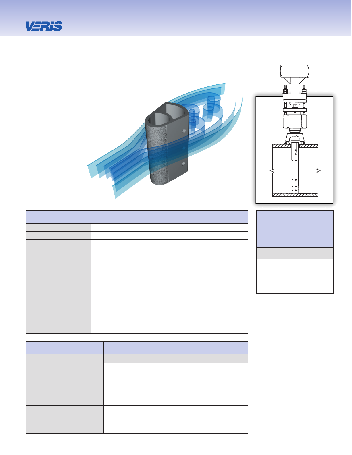
V150 Spring Lock
Pipe Connection Threaded (NPT)
Mounting Type Spring loaded sensor with packing gland
• Best valued model
• Blow-out and leak proof design
Features and
• Preloads sensor to opposite wall
Benefits
• Four times stronger than conventional mountings
• Eliminates need for opposite end support
• Compensates for changes in pipe diameter
due to pressure, temperature or mechanical force
• Air (compressed, combustion)
• Natural gas
Applications • Water (raw, cooling, feedwater)
• High velocity fluids
• Steam
Special Designs—
• Custom mounting, lengths, materials,
Consult Factory
instrument connections, etc.
• Short straight run
Model Specifications V150
Sensor Code 05 10 15
Sensor Diameter 7/16” (11mm) 7/8” (22mm) 1-3/8” (35mm)
Accuracy ±1% of flow rate; ±0.5% if calibrated
ANSI Class* 600# 600# 600#
Pipe Size
2”- 6” 6”- 42” 12”-60”
(50mm-150mm) (150mm-1050mm) (300mm-1500mm)
Instrument Connection 1/2” NPT 1/2” NPT or Direct Mount
Components Furnished Weld coupling, Spring lock mounting assembly
Weld Coupling Size 3/4” NPT 1” NPT 2” NPT
The Most Accurate and Reliable Technology
for Measuring Gas, Liquid and Steam…
Developed from aerospace technology, the Verabar®
averaging pitot flow sensor provides unsurpassed
accuracy and reliability. With its solid, one-piece
construction and bullet shape, the Verabar
makes flow measurement leak proof
and precise.
The unique sensor shape
reduces drag and flow
induced vibration.
The location of the
low-pressure ports
eliminates the potential
for clogging and improves
signal stability.
* DIN and JIS flanges available. Consult factory.
Page 2
Veraba r
®
Verabar
Flow Calculation
Program
Flow Calculation
Program
5.
Flow Calculation
All Verabar applications require a flow calculation to verify
the DP, pressure and temperature limits, structural limits
and to size the transmitter. The Veracalc PC Program
is for use by representatives and end users. It is easy
to operate and includes steam tables.
V150 Spring Lock
Verabar®Regular Models
4.
Select Model from Page 3
Use the Ordering Information table on Page 3 to determine your
model number.
Short
Straight Run
Consult Factory
(V) Vertical
(H) Horizontal
Pipe Size _____ Sch _____
Pipe ID _____ and
Wall _____ Pipe Mat’l _____
Wall
Height (H) _____
Width (W) _____
Wall _____
Duct Mat’l _____
Dimension
Verabar spans
(H) or (W)
Fluid Name: Maximum Normal Minimum Units
Flow Rate
All
Temperature @ Flow
Fluids
Pressure @ Flow
Gas
Specific Gravity, or
Molecular Weight
Liquid Specific Gravity
Steam Veracalc Program can calculate Density from Temperature and Pressure
ID
W
H
2.
Pipe or Duct Orientation
3.
Enter Flow Conditions
1.
Enter Pipe Dimensions or Duct Dimensions
Furnish the following information:
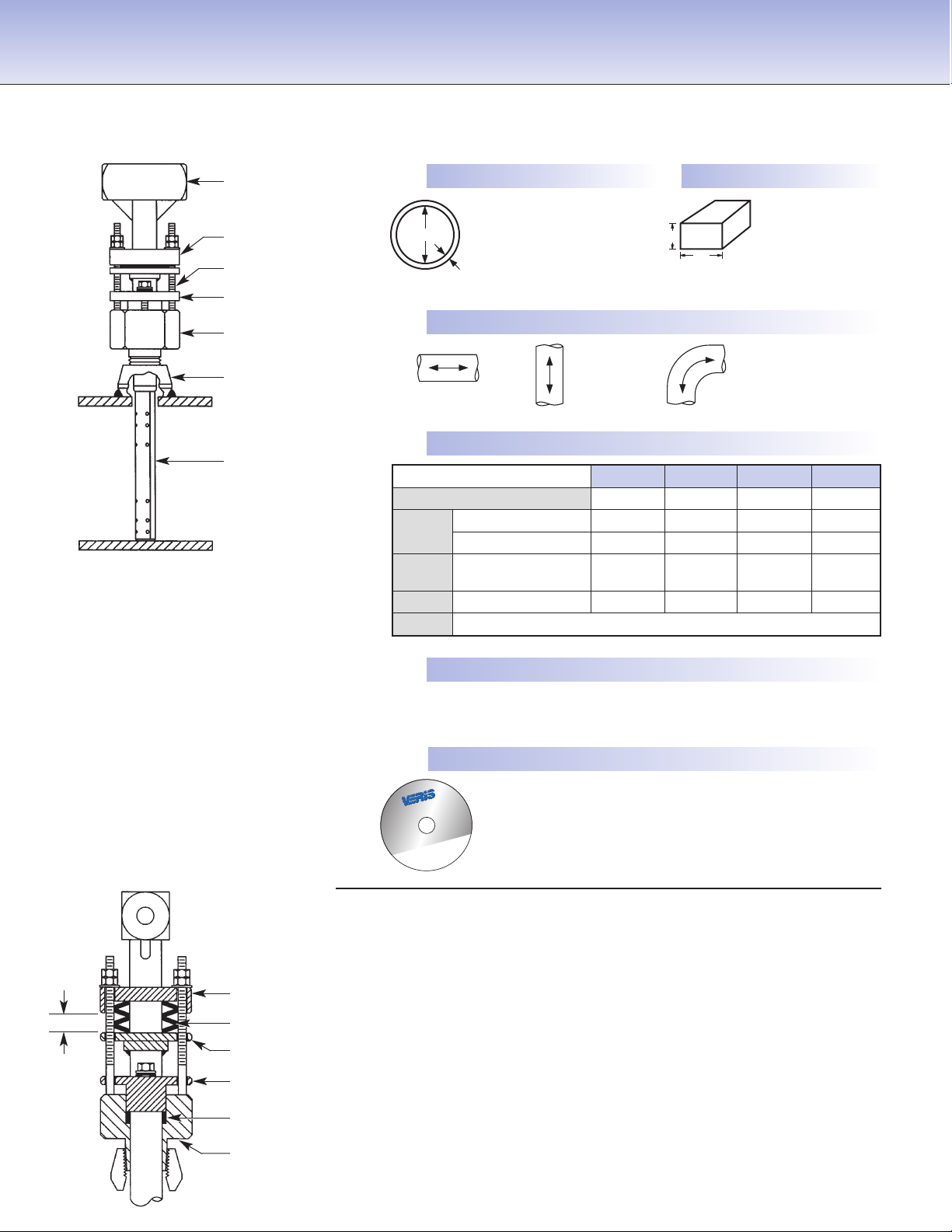
Model V150
Load
indicator
gap
Load plate (SS)
Load springs
Indicator ring (SS)
Graphite packing
Follower (SS)
Spring Lock
body (SS)
Spring Lock Mount
• Design ensures the sensor is sealed, locked and pre-loaded to the
opposite wall, regardless of changes in pipe diameter due to pressure,
temperature or mechanical vibrations.
• Leak-proof…compensates for differential in packing and body growth
rates due to increased temperatures.
• Increases sensor strength (eliminates the need for an opposite wall
support). A locked, pre-loaded sensor is four times stronger than
a non pre-loaded, cantilevered sensor.
• Spring Lock is engineered with three standard spring configurations
equivalent to ANSI class 150#, 300# and 600# ratings.
• By loading the sensor and packing independently, the sensor can
move axially to maintain a precise load on the pipe wall.
Instrument head
(SS)
Packing body (SS)
(Graphite packing)
Weld coupling (CS)
(SS-opt)
Sensor (316SS)
Spring Lock
load plate (SS)
Studs & nuts (SS)
Packing follower (SS)
Page 3

Code Options
WNS
For stainless steel pipes.
For V150, furnished with one SS weld coupling.
V150 8”sch40 10 H R C2NC Typical Model Number
Ordering Information
*
For high pressure (>500psig) or high temperature (>500°F), remote mount RTD in a thermowell is preferred.
† Assuming adequate heat dissipation for transmitter.
Model Regular
V150 Spring Lock
Pipe Size and Schedule or Exact ID and Wall Thickness
Code Sensor Pipe Size Range
05 2” to 6” (50mm to 150mm)
10 6” to 42” (150mm to 1050mm)
15 12” to 60” (300mm to 1500mm)
Code Pipe Orientation
H Horizontal
V Vertical
Instrument Connections
(Select Remote or Direct Mount)
(Transmitter sold separately)
Remote Mount Transmitter Direct Mount Transmitter
(1/2” NPT) (Flanged 450°F/232°C Max.)†
Parallel Regular RTD
*
Valve Transmount Mass Transmount
*
Manifold
PR D T F G E M
Instrument Valves (Opt.) Manifolds (Optional)
Remote Mount Direct Mount
Needle Gate 3-Valve 5-Valve
C2NC (CS) C2GC (CS) F3SC (CS) F3HC (CS) F5SC (CS) F5HC(CS)
C2NS (SS) C2GS (SS) F3SS (SS) F3HS (SS) F5SS (SS) F5HS (SS)
1/2” NPT Soft Seat Hard Seat Soft Seat Hard Seat1/2” NPT
Explsn. Proof
Remote
RTD
Integral
RTD
Integral
Integral
Optional
Page 4

6315 Monarch Park Place •Niwot, CO 80503 USA •Phone: 303-652-8550 •Fax: 303-652-8552
E-Mail: contact@veris-inc.com
•
Website: www.veris-inc.com
True Performance in DP Flow Measurement
PSS-150 (1/07)
Printed in USA
ISO 9001 Certified
 Loading...