

Page 1
1.0 SCOPE
These instructions provide procedures for installing the
V150 Verabar flow sensor. Procedures are given for all
industrial flow measurement applications including
liquid, steam and gas service for both horizontal and
vertical piping configurations.
2.0 RECEIVING INSPECTION
The following tasks should be performed as part of the
receiving inspection procedure:
• Check items received against the packing list.
• Check sensor nameplate for proper model num-
ber, serial number and customer number.
• Verify that the actual pipe diameter matches the
ID stated on the sensor nameplate.
• Check the bullet shaped sensor tube for any
signs of damage. Damage to the sensor tube
may result in erroneous flow readings.
• Check the round cover tube for any damage.
Damage to the cover tube may prevent the
packing from sealing properly.
3.0 SAFETY PRECAUTIONS
The following tasks should be conducted prior to installing the Verabar flow sensor:
• Check maximum operating conditions on the
flow sensor nameplate and verify that they
exceed the maximum conditions of the
installation. If any pressure, temperature or
flow limits will be exceeded, consult the factory
before proceeding.
Verabar V150
INSTALLATION INSTRUCTIONS
• Check that the pipe is depressurized and drained
prior to installation.
• The Spring-Lock Model V150 is designed for
carbon and stainless steel pipes with a schedule
10 or heavier wall thickness. The V150 should
be used with PVC, copper, aluminum, cast
not
iron or thin-walled pipes or ducts. If there is any
question as to the proper application for a model
V150, consult the factory.
4.0 INSTALLATION PREPARATIONS
4.1 Location
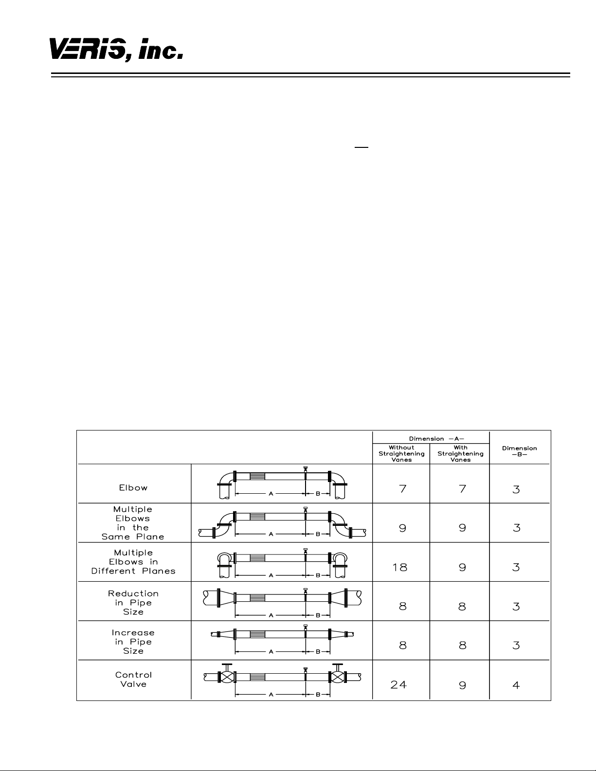
For the most accurate flow measurement, a minimum
straight run of pipe is required. Table 1 shows the
minimum straight run requirements.
If longer straight runs are available, position the
Verabar such that the ratio of upstream straight run to
downstream straight run is approximately 4 to 1. If
straight run lengths are less than the values stated in
Table 1, consult the factory for additional accuracy and
location information.
Position straightening vanes such that the end closest
to the Verabar is half way between the Verabar and the
closest upstream configuration. For elbow installations,
mount the Verabar in the same plane as the closest
upstream elbow.
Piping Configuration
Table 1. Straight Run Requirements
Page 2
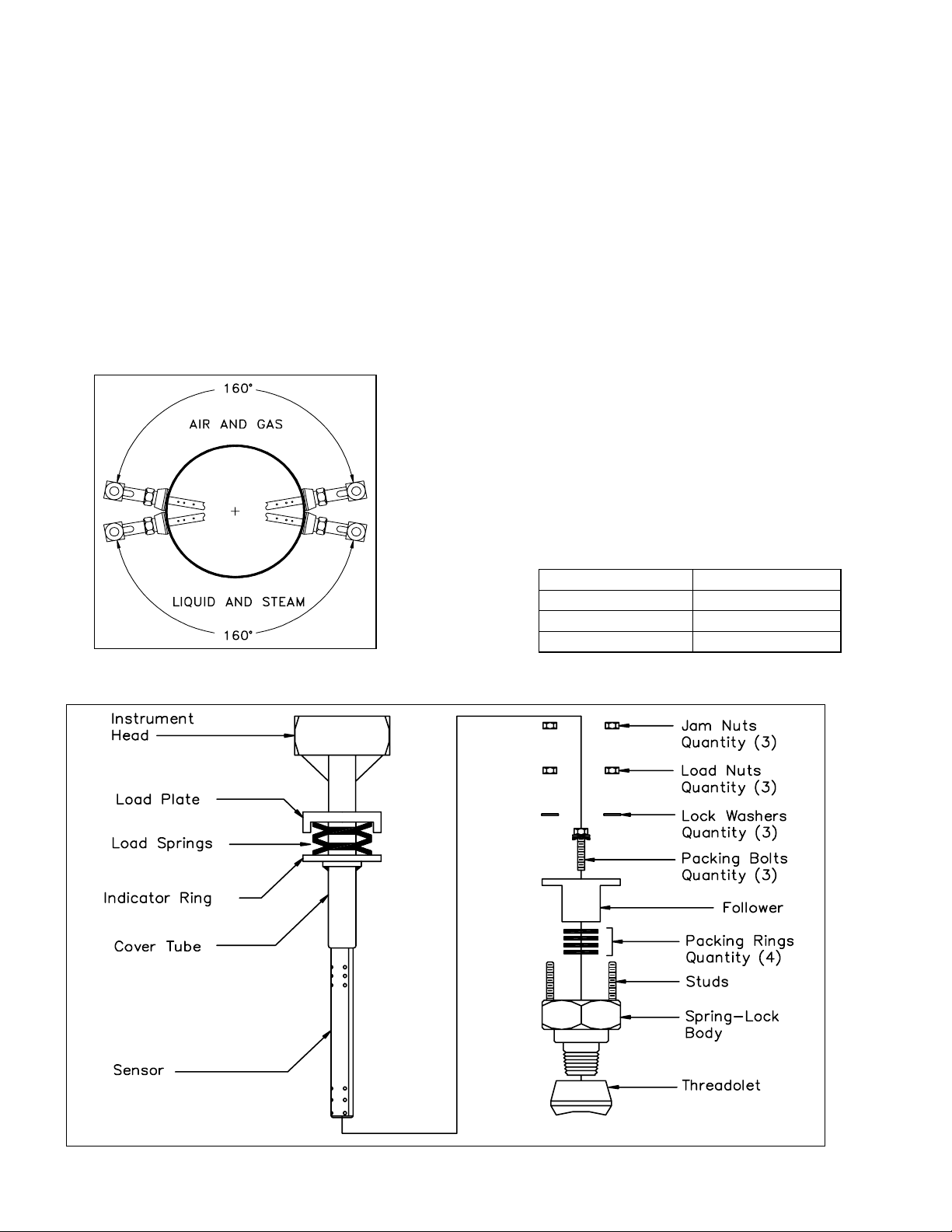
4.2 Orientation
Verify the proper sensor orientation by checking for an
“-H” (horizontal piping) or a “-V” (vertical piping) in the
model number on the Verabar name plate.
4.2.1 Horizontal Piping
For air or gas installations, mount the Verabar in the
upper 160° of the pipe to allow any condensate to drain
into the pipe (Figure 1). For liquid or steam installations, mount the Verabar in the lower 160° of the pipe.
This allows any entrained air to bleed back into the pipe
for liquid applications and allows condensate to collect
in the instrument piping for steam applications.
4.2.2 Vertical Piping
The Verabar may be mounted in any location around
the circumference of the pipe for vertical piping
applications.
Figure 1. Verabar Orientation in Horizontal Pipe
Figure 2. Verabar Model V150
4.3 DP Transmitter/Local Indicator
Location
When choosing a Verabar location, consider the DP
transmitter/local indicator location:
• The transmitter must be mounted below the
Verabar for liquid and steam applications.
• The transmitter must be mounted above the
Verabar for air and gas applications.
4.4 Installation Drawings and Bill of
Materials
Additional information is available in the Installation
Drawings and Bill of Materials VB-7061 (also on the
VeraData CD). It contains standard and alternate
transmitter locations and a complete bill of materials
based on the fluid type and sensor orientation on the
pipe.
5.0 INSTALLATION PROCEDURE
5.1 Drill Hole in Pipe
• Completely depressurize and drain the pipe prior
to installation of the Verabar.
• Mark the location of the hole through which the
Verabar will be mounted. Use a center punch to
mark the hole to prevent the drill bit from walking
on the pipe.
• Drill the pipe with the proper sized hole per the
following table:
Sensor Size Hole Dia
V150-05 1/2" (13mm)
V150-10 1” (25mm)
V150-15 1-1/2” (38mm)
• Deburr the hole on the inside of the pipe.
Page 3

5.2 Weld Threadolet to Pipe
• With the follower and packing rings already in
place, loosely insert the sensor into the SpringLock body (see Figure 2). Thread the SpringLock body into the threadolet (hand tight), then
insert the complete assembly into the pipe. This
will assure proper alignment of the threadolet to
the hole already drilled in the pipe.
• Using the appropriate weld gap (1/16” [1.5mm]
typical), tack weld the threadolet into position,
then remove the sensor and Spring-Lock body.
Protect threads on the threadolet and finish
welding the threadolet to the pipe per applicable
codes (see Figure 3).
Figure 3. Weld Gap
5.3 Thread Packing Body into Threadolet
Using appropriate pipe thread sealant, thread the
Spring-Lock body into the threadolet.
5.4 Insert Sensor
• With the follower and packing rings already in
place (factory assembled), insert the sensor into
the Spring-Lock body until the tip of the sensor
hits the opposite side of the pipe. Note, the three
studs must pass through the indicator ring and
the load plate.
• Align the head of the sensor so that the arrow
labeled “flow” on the head is in the direction of
the flow in the pipe to within 3° (Figure 4).
Maintain the head in this position for the
remainder of the installation.
• Place the three lock washers and the three load
nuts on the studs and tighten. Tighten the load
nuts until the load plate is 0.050” (1.3mm) from
the indicator ring for –05 and –10 sensors. For
–15 sensors, the load plate should be 0.063”
(1.6mm) from the indicator ring (Figure 6). For
–05 sensors, this can be done by tightening all
the load nuts until the load plate just touches the
indicator ring and then backing off all the load
nuts one complete turn. For –10 and –15
sensors, this can be done by tightening all the
load nuts until the load plate just touches the
indicator ring and then backing off all the load
nuts ¾ of a turn. The load springs are now
properly set.
• Thread on the three jam nuts and tighten until
they are resting hand-tight against the lock nuts.
Place a backup wrench on the load nut to
prevent it from rotating. While not allowing the
load nut to rotate, tighten the jam nuts 1/8 turn
beyond hand tight.
Figure 4. Orientation of Flow Arrow
Page 4

• Using a torque wrench, tighten the three packing
bolts to the appropriate torque value listed in the
table below.
Sensor Size Packing Bolt
Torque (in-lbs)
–05 50 4.2
–10 100 8.3
–15 170 14.1
Note: The weld on the weld ring (Figure 6) should
not contact the top surface of the follower. If the weld
on the weld ring comes into contact with the follower,
the sensor will not be properly bottomed in the pipe.
If this occurs, consult the factory before proceeding.
Figure 5. Spring-Lock Cut Away
Packing Bolt
Torque (ft-lbs)
5.5.2 Manifold
If the Verabar has a direct or integral manifold, be sure
the high and low-pressure block valves are shut off
prior to repressurizing the pipe.
5.6 Pressurize Pipe and Retighten Bolts
Pressurize the pipe and check for leaks. If leaks are
present, retighten the packing bolts until leaking is
eliminated. Verify that the distance between the load
plate and the indicator ring is approximately 0.050”
(1.3mm) for –05 and –10 sensors and 0.063” (1.6mm)
for –15 sensors; make adjustments as required.
The Verabar is now properly installed (Figure 7).
Figure 7. Installed V150
Periodic Maintenance
The assembly should be periodically checked. Verify
Figure 6. Proper Spring Compression
that no leaks are present. Tighten the packing bolts if
necessary.
5.5 Install Instrument Valves or Manifold
5.5.1 Valves
If the Verabar does not have a valve head, install
instrument valves using proper thread sealant. Be sure
instrument shut-off valves are installed and shut prior to
repressurizing the pipe.
6315 Monarch Park Place • Niwot, CO 80503 USA • Phone: (303) 652-8550 IO-150-VWI-CS-022 REV B (6/08)
Fax: (303) 652-8552 • Email: contact@veris-inc.com • Website: www.veris-inc.com Printed in USA
 Loading...