

Page 1

Pub# OM20-U3-pH
1-1
U3 EC/OM/pH
Table of Contents
Section 1
1-2 Warranty
1-3 Safety
Section 2
2-1 Electronics Overview and Set-up: V.Sense Controller
2-6 Software Set-up: SoilViewer
Section 3
3-1 Implement Overview and Set-up
Section 4 SoilViewer and Controller Set-up
4-1 Overview and file naming
4-2 pH Controller overview and settings
4-8 SoilViewer messages
4-9 Optical system check
4-11 pH system check
Section 5 Field Operations
5-1 Implement and EC Settings
5-4 Optical settings
5-6 pH settings
5-9 Winterization and storage
Section 6 Maintenance and Service Procedures
6-1 #1. OM signal testing
6-2 #2. EC signal testing
6-3 #3. Testing electrical continuity
6-5 #4. Diagnosing and correcting EC signal problems
6-11 #5. Spring plunger testing and replacement
6-13 #6. Diagnosing GPS-related problems
6-14 #7. Implement lubrication
6-16 #8. Bearing replacement
6-17 #9. Optical Wear plate replacement
6-18 #10. SoilViewer Troubleshooting
6-19 #11 Establishing Bluetooth connection to V.Sense Controller
6-21 #12 U Series pH troubleshooting
Operating Instructions
Page 2

Pub# OM20-U3-pH
1-2
U3-EC/OM/pH
SoilViewer Version 2.79 or Above
Section 1
Warranty
Veris Technologies warrants this product to be free of defects in materials and workmanship for a period of
one (1) year from the date of delivery to the purchaser. Veris Technologies will repair or replace any product
returned to Salina, Kansas, which appears upon inspection to be defective in materials or workmanship.
Veris Technologies shall have no obligation under this warranty for the cost of labor, down-time,
transportation charges, or for the repair or replacement of any product that has been misused, carelessly
handled, modified, or altered.
ALL OTHER WARRANTIES OF ANY KIND, WHETHER EXPRESSED OR IMPLIED, INCLUDING BUT
NOT LIMITED TO ANY IMPLIED WARRANTY OF MERCHANTABILITY OR OF FITNESS FOR A
PARTICULAR PURPOSE AND ALL CLAIMS FOR CONSEQUENTIAL DAMAGES, ARE SPECIFICALLY
DISCLAIMED AND EXCLUDED.
Safety
Page 3

Pub# OM20-U3-pH
1-3
Important! Read the following SAFETY PROCEDURES before operating the Veris system:
• Read and understand all instructions on safety decals
• Escaping fluid under pressure can penetrate the skin causing serious injury. Avoid the hazard by
relieving pressure before disconnecting hydraulic lines. Use a piece of paper or card-board, NOT BODY
PARTS, to check for suspected leaks.
• Wear protective gloves and safety glasses or goggles when working with hydraulic and high-pressure
wash systems.
• If an accident occurs, see a doctor immediately. Any fluid injected into the skin must be surgically removed
within a few hours or gangrene may result.
• Pinch point hazard: to prevent injury, stand clear when raising or lowering any part of the Veris implement.
• Install all transport locks before transporting or working underneath.
• Detach and store implements in an area where children normally do not play. Secure implement by using
blocks and supports.
• Read Operations Manual before operating machine
• Review safety instructions with operators before operating machine and at least annually
• Never stand on or use tire as a step
• Do not tow the implement on public roads without the road-kit light package, or without the proper safety
equipment and licensing as required by your State Department of Transportation. Always use safety chain.
• Riders obstruct the operator’s view. They could be struck by foreign objects or thrown from the
machine.
• Never allow children to operate equipment.
• To prevent possible electrical shock, or damage to the instrument, do not connect to any power source
greater than twelve (12) volts DC.
• Do not grease or oil implement while it is in operation.
• Disk edges are sharp. Be careful when working in this area.
• Disconnect battery ground cable (-) before servicing or adjusting electrical systems or before welding on
implement.
• Remove buildup of mud, oil or debris.
• Be very careful when mapping stubble fields with a gasoline engine pickup. Be prepared if a fire starts.
• Keep a first aid kit and fire extinguisher handy.
Page 4

Pub# OM20-U3-pH
2-1
Section 2
Electronics Overview and Set-up
The U3 electronics kit includes the items shown below
Keep all diagnostics and operations manual with system when mapping.
The supplied GPS (Figure 2a or 2b) is configured to
operate with the U3 electronics. Note: V.Sense
controllers manufactured before 9/01/2016 are equipped
with the external GPS shown in Figure 2a.
The use of any other GPS requires the correct settings. The
GPS needs to output only two NEMA strings(GGA and VTG
OR RMC). The system will not run with more than two
strings. The strings need to output at 4800 baud and 1Hz
refresh rate
U3000
Implement
test box
SoilViewer
Software
OM Reference
Block
USB Serial
Adapter
EC Test Load
OM Test Load
Figure 1
Figure 2a
Note: V.SENSE controllers manufactured after
9/01/2016 contain an internal Garmin 15x GPS. No
external GPS (Figure 2a) is provided on these units.
The controller will automatically give preference to any
external GPS source connected to the GPS input. If no
external connection is recognized, the controller will
automatically source the internal GPS for signal.
Figure 2b
Page 5

Pub# OM20-U3-pH
2-2
The V.Sense Controller is mounted on the implement, and can remain on the implement due to
weatherproofing. Unless opened by operator and lid seal is damaged. If the implement is stored outside for
long-term storage, remove Controller and store it indoors.
Figure 3 U3000 Figure 4 V.Sense Controller
Figure 5 V.Sense Controller (rear)
Figure 6 V.Sense Controller (front)
pH Controller
On/Off
Turns power to
V.Sense
Controller
On/Off
3A Fuse
OM Comm
Serial communication to PC,
and GPS input
12V Power
Power cord shipped with the unit that
connects to the vehicle’s battery
Power Indicator
Indicates when power to
the controller is on
Optic Power
Delivers power to
Optical sensor with
supplied cable
EC Signal
Bluetooth
Antenna
Depth Sensor
U3 pH Comm port
Page 6

Pub# OM20-U3-pH
2-3
The pH controller is mounted on the rear of the implement and controls the functions on the
pH sampling system.
Figure 7
Backup battery and voltage isolator
These components are connected to the V.Sense controller to maintain 12 volts to the controller during
cycling of the electro-hydraulic pump. This should require no service, other than periodically testing to see
that it is maintaining a full 12 volt charge.
Figure 8
On/off
switch
Man/Auto
switch
pH
electrode
ports
Manual
sampler
Up/down
Manual
wash switch
Isolator
12V battery
Page 7
Pub# OM20-U3-pH
2-4
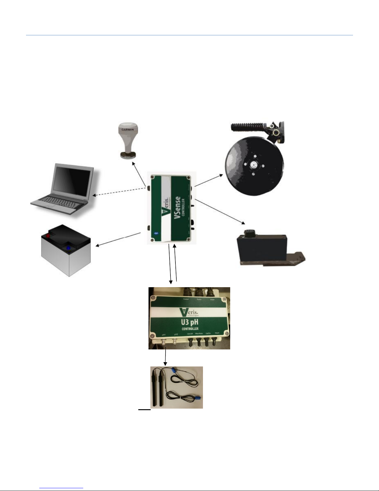
Electronic Configurations
The U3 platform is comprised of two controllers: V.Sense and U3 pH The V.Sense controller generates the
EC and Optical signals, and communicates with the U3 pH controller, and the PC (SoilViewer software)
either via serial or Bluetooth. The SoilViewer software reads the status of the GPS and U3 pH controller
signal inputs (ex. up or down proximity sensors), and initiates the pH cycling when the cycle criteria are met.
Figure 9
Page 8
Pub# OM20-U3-pH
2-5
Software Setup
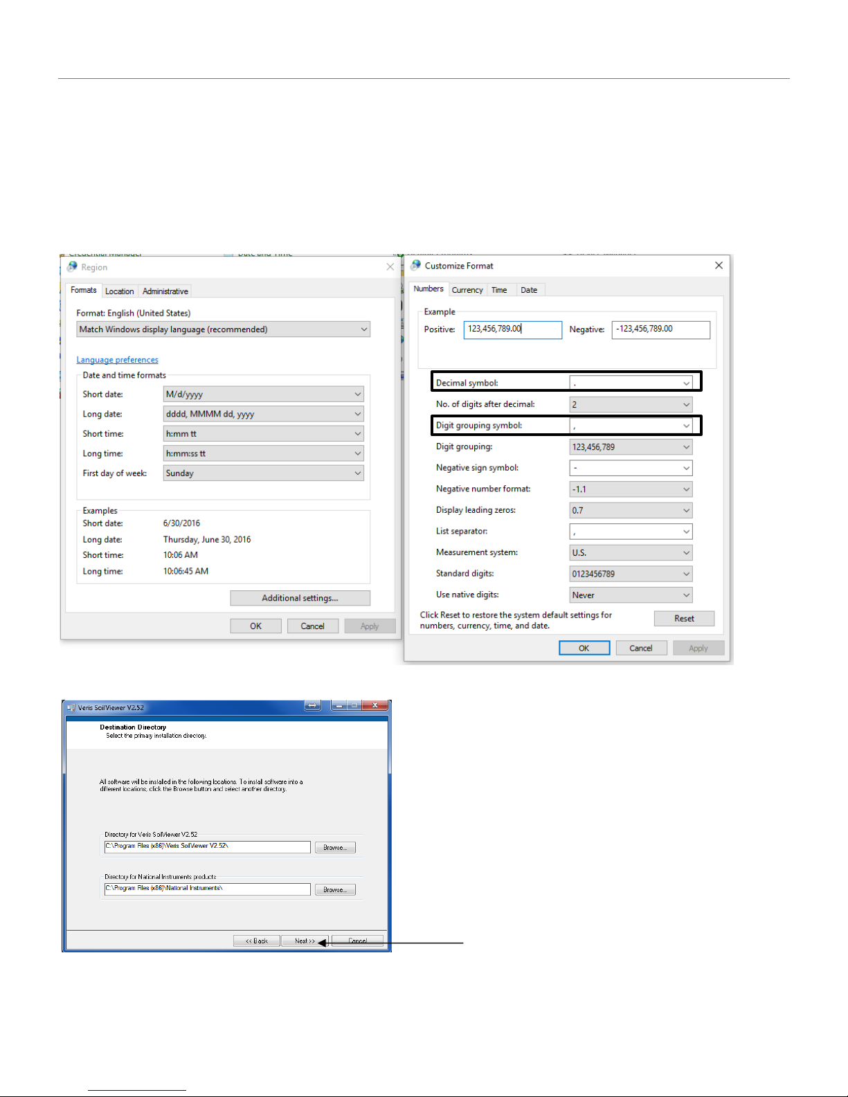
Note: For computers outside the United States of America, please make the following change to the
computer’s regional settings before installing the Veris SoilViewer Software.
Step 1: Open control panel and double click on Region
Step 2: Click on Additional Settings, the following screen will appear. The Decimal symbol needs to be a
“.” while the Digit grouping symbol needs to be a “,”. The will ensure proper operation of the software.
Once the changes have been made click OK and proceed with installation.
Figure 10
Figure 11
Open Veris flash drive and double click
on setup.exe to start the installation.
Click Next to continue through
installation
Page 9
Pub# OM20-U3-pH
2-6
Figure 12
Figures 13
Figure 14
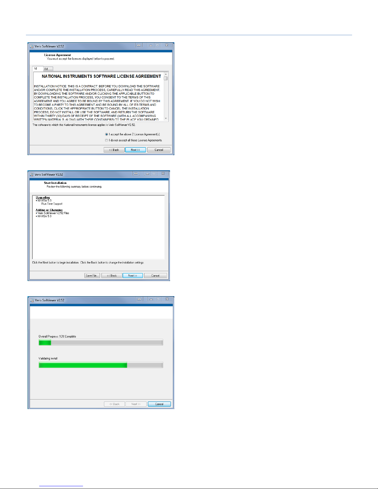
Next two license
agreements will need to be
accepted before continuing.
The installer will install
all necessary
components.
Click Next to continue through
installation
Page 10
Pub# OM20-U3-pH
2-7
Figure 15
Figure 16
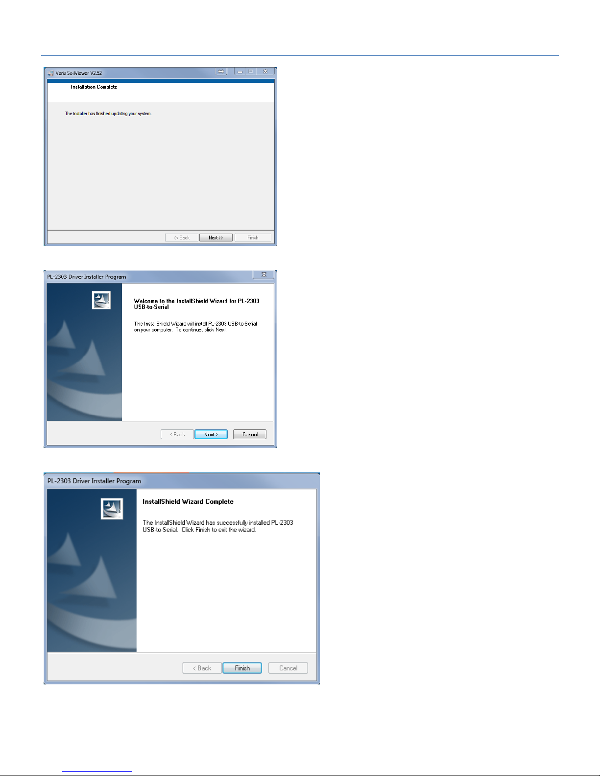
Figure 17
Click Next to install the USB drivers.
Click Next to continue through
installation
Click Finish to complete the
installation of SoilViewer.
Page 11

Pub# OM20-U3-pH
3-1
Section 3
Implement Overview and Set-up
If the unit is crated, some assembly may be required. To do so, please take precautions to ensure that the
framework is properly supported to ensure safety. Below in Figure 1 are the key components of the unit.
Figure 1
Figure 2
EC
Coulters
pH Wash
tank
pH sampler
optical row
unit
Electrohydraulics
pH
Controller
ElectroHydraulics
V.Sense
controller
Backup
battery
and
isolator
Page 12

Pub# OM20-U3-pH
3-2
Connection to Power unit
The U3 is easily connected to a UTV or small tractor.
Electronic connections are the large red and black main power leads, and the GPS com cable.
1) Connect the red power lead to positive post of battery and black to negative. The disconnect at the
front of the implement allow quick disconnection from the unit, leaving the power lead on the towing
unit.
2) The GPS comm cable connects to the Veris-supplied GPS or to your existing GPS source.
3) The remote control for the electro-hydraulic lift is routed to the operator location for raising and
lowering the unit.
Figure 3
Main
power
Remote
Control
GPS/com
Cable
Page 13
Pub# OM20-U3-pH
3-3
Electro-hydraulic lift operation
1) The remote control offers simple operation of the power unit. Push button to raise and lower. Route to
prevent damage of cable. Be sure to lower the unit only as deep as needed to obtain proper penetration
of all 4 coulters.
2) Use depth collars provided to set desired operational depth. (Figure 4)
3) Prior to transport, always install the transport lock channel on the cylinder rod. (Figure 5)
4) Periodically check the fluid level of the reservoir with the implement in the lowered position. It should be
approximately 2” from top of reservoir, with the cylinder rod in the retracted position. Unit is filled with
Mobil 424 hydraulic fluid, and should be filled with compatible fluids of viscosity index between 100 and
400 ssu.
Figure 4 Figure 5
Depth collars Transport lock
• Escaping fluid under pressure can penetrate the skin causing serious injury. Avoid the hazard by
relieving pressure before disconnecting hydraulic lines. Use a piece of paper or card-board, NOT BODY
PARTS, to check for suspected leaks.
• Wear protective gloves and safety glasses or goggles when working with hydraulic and high-pressure
wash systems.
• If an accident occurs, see a doctor immediately. Any fluid injected into the skin must be surgically removed
within a few hours or gangrene may result.
Page 14

Pub# OM20-U3-pH
4-1
Section 4
SoilViewer Set-up
Select UTV Series for
either EC and OM, or EC,
OM and pH (U3) operation.
Name the data file for sensor data. All sensor data is stored into a single file (VSENSE.RAW).
Figure 1
Figure 2
Page 15

Pub# OM20-U3-pH
4-2
The SoilViewer mapping software will automatically detect the Bluetooth or Serial port the controller is
connected to, and begin communicating. If the V.Sense controller is not detected, the software will wait 45
seconds for the connection of the electronics and search again; this will repeat until the connection is
established. If the connection is not found, unplug the serial or USB cable, restart the PC, reboot the
controllers, then and reconnect USB cable to the PC. If using Bluetooth, exit the software, and ensure the
controller is paired per procedure 11.
The conditions for mapping and storing EC and Optical data are as follows. The unit must be traveling a
speed greater than 1 mph, there must be a GPS signal received, the OM/EC Comm Light must be green,
indicating the PC and V.Sense controller are communicating properly, and the EC 0-2 value has to be
greater than -1. When all these conditions are met, the Saving Data light will be green and the EC and
Optical points will be mapped.
The pH readings on the display show continuously what each electrode is reading. When logging sensor
data, the hydraulic cylinder will hold the electrodes against the soil and record a pH reading once a
particular settle method (see settle method criteria) has been met. The minimum recording time is 7
seconds; the maximum time (default 12 seconds) is determined in the pH controller settings menu. If the
reading takes longer than 10 seconds to settle, a warning will appear that indicates the number of seconds
the reading has required to settle. When the maximum log time is reached, the hydraulic cylinder will
automatically retract and wash the electrodes. For additional information on the pH sampling sequence see
the Recording UTV pH Data section.
Before mapping, perform the OM and pH system checks to ensure proper sensor operation.
If mapping has stopped, files may be appended by selecting a previous file when prompted at the startup of
the software.
User selectable plot
colors, click on color
to change.
Sample
button for
marking
lab sample
locations
Use single map
view to show a
larger map, and
help identify
where to take
calibration soil
samples
Various system warnings will
appear here see Warning
Messages for additional details
Displays when
program is
searching for
V.Sense
controller, this
only happens
at startup.
Figure 3
Page 16

Pub# OM20-U3-pH
4-3
These indicators help the operator know
when it’s time to stop for a pH sample.
These lights indicate when the operator is
within 30%,15%, and 5% of their
designated target sampling distance. The
target sampling distance can be set in the
pH Controller Settings menu. The default
value is 65 meters, which equates to about
1 point per acre.
U3 pH Controls and Indicators. Note: these indicators will only be present when
the U3 pH Controller is turned on.
Figure 4
Figure 5
Page 17

Pub# OM20-U3-pH
4-4
pH I/O indicators
Recording U pH Data
Conditions for starting pH cycle:
1) Press Either Single Sample or Automatic Sample
OR
2) Positive EC Values (unit in ground) and Speed equal to 0 and GPS quality greater or equal to 1
Single pH sample will complete one complete pH cycle. Automatic pH will cycle every time the above
criteria are met, and the minimum distance from the previous sample (default 10 meters). This minimum
distance setting is adjustable via the pH controller settings in the menu. Automatic mode allows the
operator to traverse the field, and cycles the pH when the implement is stopped for maximum efficiency.
pH Cycle state indicator. These
correspond to the various pH
input and output functions. A
green light indicates that
parameter is active.
The settle method reports the
status of the last pH point
recorded; the time indicates how
long the sampler has been in the
pH recording state.
Figure 6
Figure 7
Figure 8
Page 18
Pub# OM20-U3-pH
4-5
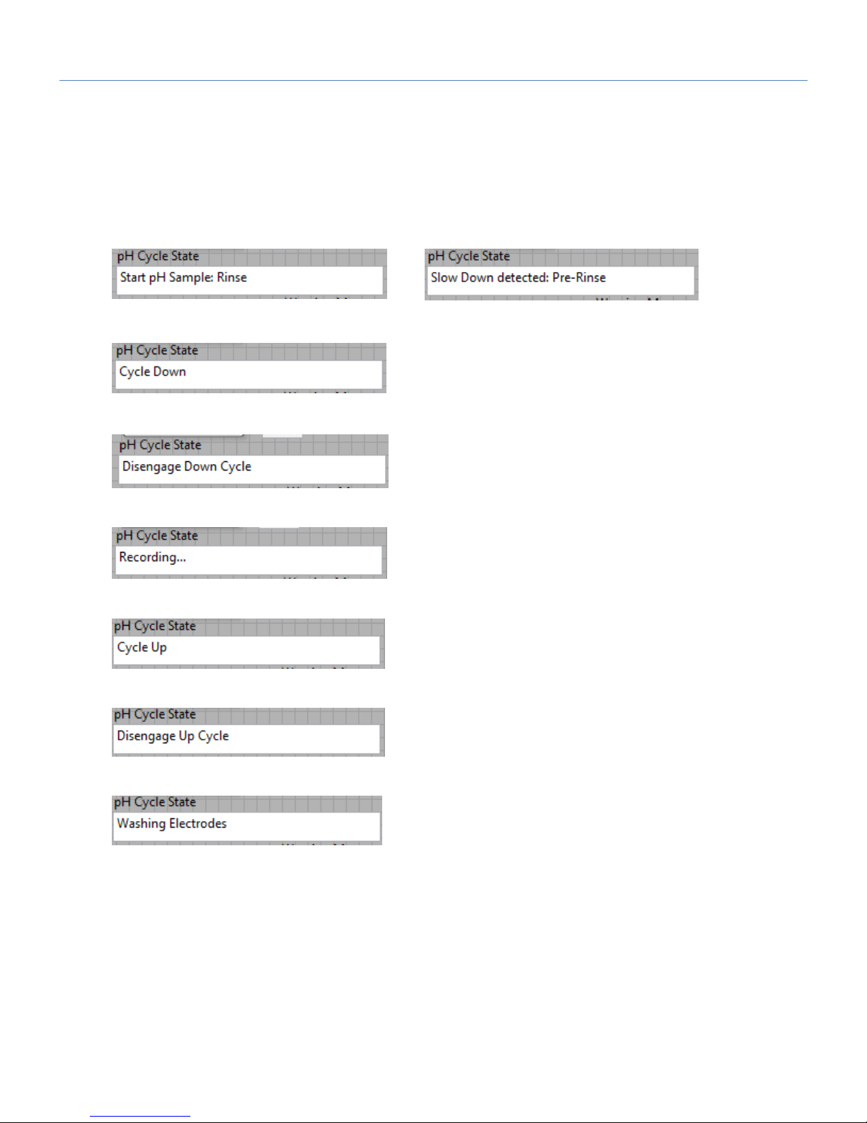
The pH Cycle State indicator will alert the operator to the current state of the pH sequence. In addition, the
indicator lights on the screen will show the state of the controller input and outputs. The information
provided in these steps is for reference only, once the conditions for starting the pH cycle have been met,
the following sequence will automatically take place.
1) Rinse electrodes for 1 second. This clears any dust that has built up on the electrode while
traversing the field. When in automatic mode, the software anticipates a slowdown, and will
automatically pre-rinse the electrodes.
OR
2) Send down command to hydraulic cylinder
3) Wait until down proximity sensor is enabled, then disengage hydraulic cylinder
4) Record sensor data (subject to settle method)
5) Cycle Up
6) Wait until Up proximity sensor is enabled, then disengage hydraulic cylinder
7) Wash Electrodes
Figure 9
Figure 10
Figure 11
Figure 12
Figure 13
Figure 15
Figure 14
Page 19

Pub# OM20-U3-pH
4-6
Settle Method Criteria
The electrodes are pre rinsed with water before cycling into the soil. This removes any dust which may
have built up on the electrodes, and establishes moisture for the pH sensor to properly function. A
measurement time of 7-15 seconds is required to allow the pH reading to move from the water pH to a
stabilized soil pH reading. The following settling methods are employed to allow the pH cycle to as quickly
as possible; while also alerting the user to potential issues.
Quick Settle (QS): Electrodes met a superior settle criterion in 8 seconds or less. The reading is stored,
and the cycle continues.
Standard Settle (S): Electrodes met standard settle criteria in less than the maximum settle time (default
12 seconds). The settled reading is recorded in the data file, and the cycle continues.
Time Out (TO): Electrodes didn’t settle within the maximum settle time. The reading was recorded;
however, one or both the electrodes didn’t meet the standard settle criteria. If 40% of your sensor data falls
in the category, consider increasing your maximum settle time.
Time Out Redo (TORD): Electrodes took longer than the maximum settle time, and the reading had
excessive noise. The software will prompt the user to pull forward 10 feet and redo the sample. No data
point will be logged in file.
Figure 16
Figure 17
Page 20

Pub# OM20-U3-pH
4-7
pH Controller Settings
These system settings can be found under Options pH Controller Setup
This example shows the pH sampling pattern on a 200’ by 200’ (61 m) grid, which is slightly denser than a 1
acre (.4 ha) grid. The EC-OM transects are 50 ft (15 m) apart and the pH samples are collected from every
fourth transect.
Wash Time – Amount of time wash water sprays
the electrodes at the end of a pH cycle. Default is 1
second. If issues arise with electrode cleaning in
sticky soils, increase to 2 or 3 seconds)
Max Measurement time – Maximum time for
electrodes to record before rejecting sample. The
range of this value can be 12-20 seconds. Default
is 12 seconds. If over 30% of readings time out
before settling, increase time to 15-18 seconds.
Min Distance between samples -- This sets he
minimum sampling density in automatic mode. This
threshold keeps the sampler from cycling close to
an existing pH sample point. Default is 10 meters.
Target distance between samples (m) – Distance
at which the software will flag the operator to stop
and take a sample in Automatic mode. Default is
65 meters, which equates to about 1 point per acre.
Other distances and per acre/hectare equivalents:
Sample Grid size
Distance
(m)
Distance
(ft)
.5/ac or .2/Ha
45
150
.625/ac or .25/Ha
50
165
1/ac or .4/Ha
65
215
Figure 18
Figure 19
Figure 20
Page 21

Pub# OM20-U3-pH
4-8
SoilViewer Warning Messages
There are warning signals programmed into the SoilViewer to warn the operator that data are not being
recorded, so that corrective action can be taken. If data aren’t being recorded, a warning beep will sound
from the computer, and the text indicator of the data that is missing information will blink. For example, if
the DGPS isn’t being received (or the NMEA string containing speed) the Fix indicator text will blink. If EC
values are negative, they will also blink. Additional messages may appear in the Warning Message Box as
follows:
Potential SoilViewer Warning Messages
Error EC_RPBT - Unit Raised out of ground, but EC readings are positive. Check for a moisture on the
toolbar or a short between all EC Coulters.
Error EC_NP - Row unit is engaged in soil, but EC readings are negative. Check for continuity, and make
sure coulters penetrating soil at least 1.5-3". Fluted coulter should run slightly deeper than optical runner.
Error EC_N30 - Excessive Negatives in EC data, check coulter continuity and soil contact.
Error OM_DPT - Row unit not penetrating soil enough. Depth of optical runner should be 1.5" or > when
mapping.
Error EC_EXMD - Excessive noise on EC 0-2 readings check continuity on coulters 2 & 3.
Error OM_LW - OM readings are too low. Check wearplate window for clarity.
Error_No Comm.- Check USB and serial connections to OM/EC Controller. Unplug USB and restart PC if
communication does not reestablish.
Error No_GPS - Check GPS settings (4800 baud, 1 hz, and only VTG and GGA Strings enabled)
*WARNING: READING NOT SAVED** pH reading did not stabilize during measurement time, and
readings showed excessive noise. Pull forward 10ft, and redo pH sample. If issue persists, check
for electrode cleanliness, and soil contact.
Note: all depth settings recommendations are for normal conditions. Local soil conditions
may require deeper settings (if soils are dry) or shallower settings (if soils are wet or
sticky).
Figure 27
Page 22

Pub# OM20-U3-pH
4-9
SoilViewer OM System Check
Select OM from the Sensor Checks drop down menu.
Figure 21
After clicking the button the following will appear:
Figure 22
Make sure the window is clean and in good condition. (see below) Place the dark side of the reference
block under the window, and click continue. Then the next message will appear.
Figure 23
Flip the reference block over to the light side and place under the window, and click continue. Then this
message will appear:
or
Figure 24
The reference values have been stored, and the system is ready for mapping.
Page 23

Pub# OM20-U3-pH
4-10
Page 24

Pub# OM20-U3-pH
4-11
Optical Wearplate
Below is a comparision of two wearplates. The left is a brand new wearplate, and the right has about 2500
acres on it. Inspect the leading edge,shown below, as the steel wears the window can chip or crack. As
this contiues to wear it will eventually need replaced.
Figure 25
Wearplates will wear differently in every type of soil, so check it often. To replace wearplate refer to
Procedure #9
Page 25

Pub# OM20-U3-pH
4-12
pH System Check
Select pH from the Sensor Checks drop down menu
Figure 26
Figure 27
Figure 28
The software will prompt for the electrodes to be inserted into pH buffer 4 solution; Carefully lower
electrodes into solution cup (figure 13). Press 1 to continue with calibration or 2 to exit. Tips: Don’t
overfill solution. Cup only needs enough solution to immerse electrode tip and face. Don’t reuse
solutions.
Figure 29
Operator will be asked to continue the
system check or restore ideal settings.
Page 26

Pub# OM20-U3-pH
4-13
The software will read the electrodes for 10 seconds, displaying the output (as it counts seconds):
Figure 30
After 10 seconds, the software will display the final pH reading and offer the options to Accept pH 4
buffer readings; Redo pH 4 buffer readings; or Cancel pH electrode system check. If the readings
are satisfactory, press Accept; if the readings are suspect, press Redo to return to re-do pH 4.
Figure 31
After accepting the pH 4 buffer readings, the software will prompt for the electrodes to be inserted
into pH 7 buffer solution. Remove the pH 4 buffer solution from the cup. Rinse the electrodes,
electrode holder, and solution cup using the manual wash for at least 10 seconds. Lower the pH
electrodes into solution cup containing pH buffer 7 solution.
Figure 32 and 33
Press continue to proceed with the calibration. The software will read the electrodes for 10
seconds, displaying the output. After 10 seconds, the software will display the final pH reading and
offer the options to Accept pH 7 buffer readings; Redo pH buffer 7 readings; or Cancel pH
electrode system check. If the readings are satisfactory, log pH 7 reading and press continue; if
the readings are suspect, press redo to return to pH 7 step.
Page 27

Pub# OM20-U3-pH
4-14
After accepting the pH 7 buffer readings, the software will determine if each electrode’s response
is sufficient to provide suitable readings. A score is displayed for each electrode; the acceptable
score range is between 75 and 102. If both electrodes are within this range, the software will
display the following screen:
Figure 34
If an ‘X’ is displayed beside one or both electrodes’ scores, this indicates that one or both of the
electrodes did not perform well enough for continued reliable use. The electrode(s) responsible for
failed system check should be removed and either buffed lightly with emery cloth or sandpaper, or
replaced and the system check procedure repeated.
Tip: It is still important to perform the system check at least daily, since this process is important to
test electrode quality.
Page 28

Pub# OM20-U3-pH
5-1
Section 5: Field Operations
Field Operations: Implement
Checking Electrical Signal Continuity and Electrode Isolation
It is recommended that you perform the Electrical Signal Continuity and Electrode Isolation test
procedure before first field use (see Service Procedure 3). While these tests were made at the
factory, there is the possibility a problem developed during shipping. Performing these tests on the
new implement allows you to get familiar with the process under ideal conditions. It is advised that
you perform this test on a routine basis (every 10 hours of data collection) to ensure you are
obtaining reliable data. KEEP OHMMETER, TEST LOAD AND TEST BOX WITH THE MACHINE
AT ALL TIMES.
Setting Operating Depth
Begin field operation by lowering unit into soil. For good electrical conductivity, all coulter
electrodes must be in direct contact with moist soil, at all times and in every region of the field. An
initial depth of 1-2” (2.5-5 cm) is recommended. To insure this depth is consistently achieved, 400600 lbs. (180-275 kg) of additional weight are normally required on non-pH units. Veris offers
optional weights, or they can be supplied by the customer. Do not adjust the tension on the coulter
electrode springs to increase soil contact or penetration. They are pre-set at the factory with the
proper tension. Note: all depth settings recommendations are for normal conditions. Local
soil conditions may require deeper settings (if soils are dry) or shallower settings (if soils
are wet or sticky).
Field Condition
Field should be in a uniform state. Mapping after intensive primary tillage is not recommended. The soil
must have a minimum of 20% available water, and cannot be frozen. If rocky conditions exist, slow down
and make sure rock guards are in place
Figure 1
Turn the top link to adjust the tilt so that the unit runs level. This is the optimum setting for all field
conditions. Extending the top link will cause the rear of the unit to tip backward. Shortening the top link will
cause the unit to tip forward.
Speed
Proper field operating speed depends on field conditions. Because of the importance of consistent contact,
the unit must not be allowed to bounce over rough fields at high speeds.
Top Link
Page 29

Pub# OM20-U3-pH
5-2
Pulling Vehicle
The implement may be pulled with a variety of vehicles: UTV, 40 hp tractor or a 4WD pickup.
• Be very careful when mapping stubble fields with a gasoline engine. Be prepared if
a fire starts.
Swath width and Navigation
Setting the swath width and navigation system is at the discretion of the customer. A 50’-75’ (15-23 m)
swath works well in most areas. Several methods of navigation are possible: following previous crop rows,
swath guidance, or auto-steer. While it is important to map in a consistent pattern, it isn’t absolutely critical
that each pass be exactly the same distance from the previous pass.
To help insure the quality of your data, please follow these guidelines:
1. View SoilViewer map frequently during data collecting; watch for:
• Negative EC readings or excessive noise in the data.
• EC readings should fluctuate gradually as you drive across the field, relating to
soil changes. If readings change erratically, or show values not typical of soil
conductivity in the area—such as >100, perform tests 4 and 5 below.
• Watch for streaks, stripes, unnatural patterns, and missing data points.
2. Perform Signal test (Procedure #3):
• at least once a day during mapping season
• every 10 hours of mapping
• after extended periods of non-use
• after replacing or repairing coulter-electrode components or wiring
• whenever readings are questionable
3. Keep all electrical connections dirt and moisture-free
4. Limit speeds in rough or rocky field conditions. This will improve data quality, and will also lengthen the
service life of the implement components. NEVER EXCEED 15 M.P.H. FIELD SPEED.
Page 30

Pub# OM20-U3-pH
5-3
OM Data Quality
Monitoring the window – This can be done by watching OM readings at row ends when unit is raised, if they
are not within 10% of the initial raised readings check windows for mud, smearing, and/or window breakage.
Varying Field Conditions – In order to have high data quality the field conditions need to be the same for an
entire data set. Any of the following can affect data quality: variances in soil moisture do to different
management conditions (ex. tillage), change in down pressure or depth gauge wheel setting. If conditions
change within a field, start a new file.
The map example in figure 2 shows mapping on two separate days; the left portion of the map was mapped
under on a different day under different soil conditions. This part of the field should have been mapped on a
separate file. This same effect can occur also by adjusting down pressure or sensor depth.
Figure 2
Page 31

Pub# OM20-U3-pH
5-4
Field Operations : Optical Row Unit
Setting Sensor Depth
To adjust sensor depth, move “T” handle forward or back accordingly
• For shallower sensing, move handle forward.
• For deeper sensing move handle back
Figure 3
Setting Closing wheel angle
The rear closing/depth wheels are adjustable to increase or decrease the amount of soil pinched into the
furrow made by the optic module. There are three adjustment positions, and the unit is shipped in the
center position. (Figure 4)
“T” Handle
OM Sensor
Adjustment bolts
Adjust forward for more
aggressive closing action
Adjust rearward for less
aggressive closing action
Figure 4
Page 32

Pub# OM20-U3-pH
5-5
Setting Optical Row Unit Down pressure
The spring down pressure settings on the optical row unit are determined by the firmness of the soil being
mapped.
For soft soils, low to medium spring pressure should be adequate.
In firm soil conditions, down pressure may need to be added.
Adjust by rocking adjuster rearward with a 1 1/8” wrench and clicking into higher lower position. Fully
rearward is maximum down pressure and fully forward is minimum.
Setting Row Cleaner Depth
The row cleaner mounted on the coulter operating ahead of the OM/pH runner is critical in removing crop
residue from the runner path. It is fitted with an adjustment screw to limit the down float of the row cleaner
fingers. Once you have set the operational depth of the implement, adjust the adjustment screw until the
fingers are lightly contacting the soil. (figure 6)
If the fingers are moving too much soil, adjust the screw downward to raise them up.
If the fingers are not clearing enough residue, screw upward.
Firmly lock jam nut to hold in place.
Figure 6.
Adjustment screw
& jam nut
Maximum
Minimum
Figure 5.
Page 33

Pub# OM20-U3-pH
5-6
Field Operations: pH Sampler
While the EC and OM sensors are continuously logging data when the unit is in the soil and moving, the pH
sampler will only cycle when the unit is in “Automatic” mode and the unit is fully stopped.
Important Note—
a) Keep the electrodes from freezing.
b) Always make sure the electrodes are in the raised position before mapping.
Prior to mapping, there are several items you need to check concerning the pH sampler.
1) If the electrodes have not been installed, install by loosening the allen-head pinch bolts on the
sampler and installing the electrodes.
Slide electrodes down all the way.
2) Connect the front electrode to pH 1 and the rear to pH 2 (figure 8).
3) Turn on controller and switch to Manual. LED’s will indicate when the switch is active. (figure 8)
4) Fill wash tank with water and make sure that valve handle is pointed toward supply hose. This is a
three position valve. Forward as show in Figure 9 is “on”. Vertical is “off” and rearward is for tank
drainage.
Figure 7.
Figure 8.
Page 34

Pub# OM20-U3-pH
5-7
Figure 9.
Note: You may have to bleed the air from the system to allow the pump to properly prime. This is
accomplished by removing one of the wash hoses by releasing the auto-lock fitting. Simultaneously push
down on lock collar and pull up to release hose. Press manual wash switch until pump is primed, and push
hose back into auto-lock fitting. (Figure 10)
Figure 10.
Tank valve
Forward -- on
(shown)
Vertical – off
Rearward -- drain
Auto -lock
Lock collar
Page 35

Pub# OM20-U3-pH
5-8
5) Raise sampler into top position and press manual wash switch. Check to see if both electrodes are
being sprayed correctly for cleaning. (figure 11)
6) If necessary, adjust by loosening set screws and re-adjusting. (figure 12)
7) Raise sampler to top position, switch to Automatic, and you are ready to begin mapping.
Sampler will now lower every time you stop in the field. Information on sampling density and swath
width is covered in Section 4.
RH wash jet is
focused on rear
electrode
LH jet is focused on
front electrode
Figure 11
Figure 12
Page 36

Pub# OM20-U3-pH
5-9
Winterization and Storage
During periods when the temperature is below freezing overnight, you must take precautions to protect the
wash system and ISE electrodes.
1) Turn off tank valve and manually depress wash switch until no more water appears from the wash
jets. If for longer term, rotate valve rearward and drain tank.
2) Remove drain plug from bottom of filter mounted under wash tank.
3 Remove wash hoses at auto-lock fittings and blow out check valves and jets with compressed air.
4) Remove pH electrodes from unit.
Figure 13.
Figure 14.
Figure 15.
Page 37

Pub# OM20-U3-pH
6-1
Section 6: Service and Troubleshooting Procedures
Procedure #1 OM Signal Testing
Perform this test weekly or every 50 hours of data collection to ensure you are obtaining reliable data,
and whenever OM data is questionable. The purpose of this test is to insure the instrument is performing
properly.
The V.Sense Controller is shipped with an Instrument Test Load (Part No. 46403) that will enable you to
quickly check the instrument to ensure that it is functioning properly. To perform this test:
1) Disconnect the optical power cable from the OpticMapper/EC Controller.
2) Connect the test load to the Optical Power port.
3) Switch on the OpticMapper and view display on SoilViewer.
4) The display should show:
Red: 833 +/-10
IR: 289+/-10
5) If the readings vary significantly contact Veris service department.
6) Once the test is complete, remove the test load and reinstall the optical power cable.
Figure 1.1 OM Signal Test Load installed
OM Signal Test Load
Page 38

Pub# OM20-U3-pH
6-2
Procedure #2: EC Signal Testing
Perform this test weekly or every 50 hours of data collection to ensure you are obtaining reliable data,
and whenever EC data is questionable. The purpose of this test is to insure the instrument is performing
properly.
The V.Sense Controller is shipped with an Instrument Test Load (Part No. 223640) that will enable you to
quickly check the instrument to ensure that it is functioning properly. To perform this test:
1) Disconnect the signal cable from the signal terminal on the OpticMapper/EC controller.
2) Connect the test load to the signal terminal.
3) Switch on the V.Sense controller and view display in SoilViewer or Data.
4) The display should show:
0-2: 14
5) If the readings vary significantly (more than one whole number) contact Veris service
department.
6) Once the test is complete, remove the test load and reinstall the implement signal cable.
Figure 2.1 Signal Test Load installed (SoilViewer display showing proper EC readings)
Signal Test Load
Page 39

Pub# OM20-U3-pH
6-3
Procedure #3: Testing Electrical Continuity
Perform this test daily or every 20 hours of data collection to ensure you are obtaining reliable data, and
whenever EC data is questionable.
The purpose of this test is to insure that each coulter-electrode has an uninterrupted signal path from the
V.Sense controller to the disk blade. Think of each coulter-electrode and its wire path as a ‘channel’. On a
U3000, there are 4 signal channels that must be clear and isolated from one another. You will first test the
complete pathway for each channel—each coulter-electrode. One easy-to-take reading for each channel
tests the cable, wiring harness, and each coulter-electrode and disk blade. If no problems surface during
this test, there is no need to test individual components. This test should take only a couple of minutes to
perform.
To perform this test, you will need the EC Signal Test Box (part # 223707) and an ohmmeter (sometimes
referred to as a multi-meter or voltmeter). Make sure the meter is set to ohms, Ω. If a range of ohms is
available, choose the lowest setting--ohms rather than kilo or mega ohms. If unfamiliar with ‘ohming-out’ or
resistance testing, make a few trial tests before performing the Veris signal test procedure. Touching the
meter leads together will display a zero resistance reading, touching two places on the same piece of metal
will produce a nearly zero reading, touching nothing will produce an OL (overload or over limit) reading—
meaning complete resistance, and no continuity.
Figure 3.1
Remove the signal cable from the V.Sense Controller and
connect it to the terminal on the test box. This cable attaches to
the signal cable end and allows you to position the Signal Test
Box in close proximity to the coulter-electrodes.
Page 40

Pub# OM20-U3-pH
6-4
Firmly press one lead of the ohmmeter to the #1 coulter blade edge (left hand, standing behind the unit) and
the other lead to the #1 terminal on the test box. Maintain firm pressure on the ohmmeter lead touching the
disk blade. A reading of less than 2 ohms is normal. Rotate blade ¼ of a turn back and forth as you view
the ohmmeter. Any jump in the readings above 2 ohms indicates a problem.
Continue to check each coulter electrode in succession, left to right.
If any coulter electrode exhibits no continuity or resistance higher than 2 ohms, refer to Procedure #4
Diagnosing EC Signal Problems.
Connect to coulter
blade
Ohmmeter
Connect one lead to Signal Test Box
terminal (corresponding to each
coulter)
Figure 3.2 Shows testing on disk #2
Page 41

Pub# OM20-U3-pH
6-5
Procedure #4: Diagnosing and Correcting EC Signal Problems.
Use this Troubleshooting tree to work through the system, locate the problem, and take corrective action.
Figure 4.1
Page 42

Pub# OM20-U3-pH
6-6
Coulter Electrode Functions-
Each coulter electrode on the implement is part of a pair, and each pair has a distinct function.
a) Coulters 2 & 3 are the 0-2’ receptors.
b) Coulters 1 & 4 are the “charged” coulters that inject the voltage into the soil. If you are getting no
(or intermittent) readings -- continuity to one of these two coulter-electrodes is likely the cause.
If the continuity ohm test indicates a problem on a channel, you will need to determine where the
interruption is located. Listed below are detailed instructions on how to determine exactly where a
continuity or isolation problem is located:
A. Testing Cable and Wiring continuity:
1. Once a high resistance reading on a channel is confirmed, determine whether the problem is in the
wiring or in the coulter-electrode. To test all cable and wiring, place one ohmmeter lead in the Test
Box terminal pin for that channel and the other on the corresponding coulter wire terminal bolt.
Grasp connector and move back and forth during this test – vibration from rough fields can weaken
the contacts, causing intermittent breaks in continuity during operation that might not show up in a
static test. Repeat process on all coulter-electrodes.
2. If you see <2 ohms on all, test the coulter electrodes as explained in B below.
3. If you see a > 2ohms reading on any channel, separate weather pack connector and insert one
ohmmeter lead in the end of wiring harness and the other lead in the corresponding terminal on the
Test Box. If reading is < 2 ohms at that point, the problem is not with the wiring harness or signal
cable extension. It is most likely in the terminal connector wire. Check resistance in it by placing
one ohmmeter lead on the coulter wire terminal bolt and the other lead in the end of the terminal
wire socket. Replace connector wire (PN 14226) as necessary.
Page 43

Pub# OM20-U3-pH
6-7
Figure 4.2
Testing cable at end of signal cable wiring harness
Figure 4.3
Separating Weatherpack connector 4.3 Testing terminal connector wire
4. To ohm out the wiring harness, disconnect from the implement and check continuity through the
harness as shown in Figure 4.4. While doing so, check the pins and the sockets of the 12-pin
connector for corrosion and fit.
Page 44

Pub# OM20-U3-pH
6-8
Figures 4.4 and 4.5. Checking continuity of signal harness, with one ohmmeter lead contacting pins in
connector and other lead contacting corresponding coulter-electrode.
Note: intermittent electrical problems are difficult to diagnose. Flex wiring and connectors while checking
continuity.
B. Testing Coulter-Electrode continuity
1. Place ohmmeter lead on terminal wire bolt and other lead on disk blade. Rotate blade ¼ turn. If
readings are consistently above 2 ohms, check for excessive corrosion at the coulter blade mounting
bolts, or the terminal located near the coulter pivot. Make sure that high ohm readings are not due to
poor contact between blade and ohmmeter lead. Re-test holding lead firmly against edge of blade,
removing rust or paint if necessary.
2. If ohms jump over 2 ohms when the blade is rotated, and you were careful to maintain good contact
between the lead and the blade, the problem is likely inside the hub. Because electrical signals
cannot be sent consistently through the coulter bearing, Veris has designed a more reliable path for
the EC signal to travel. A special hub with a spring plunger presses against the spindle of the
coulter, serving as a commutator. Shown below is a cut-away view of the hubcap and plunger
assembly. When ohm readings jump during blade rotation, it is due to the greased rollers on the
bearing making intermittent and inconsistent contact. See Maintenance and Service procedure #5:
Spring Plunger adjustment and replacement on adjusting and replacing spring plungers.
U3000 Series – Use Middle
and Current Pins
Page 45

Pub# OM20-U3-pH
6-9
Figure 4.6
C. Testing Coulter-Electrode isolation
If continuity tests show no excessive resistance on any channel, yet erratic soil EC readings continue, or if
EC readings do not drop to –1 when unit is out of the soil, it is possible that the channels are not isolated.
This could be the result of a pinched wiring cable, causing channels to short out. Or, one of the coulterelectrodes is no longer insulated properly from the frame or adjacent coulter-electrodes.
1. If EC readings do not drop to –1 when unit is raised, disconnect
signal cable extension from implement. If readings don’t drop to
-1, the problem is with the signal cable extension. If readings
show -1, re-insert the signal cable extension into the implement.
Disconnect the terminal connector wire from each coulter
electrode. If readings don’t drop to –1, the problem is with the
wiring harness. If this is the case, you should replace the wiring
harness. If readings do drop, re-insert the signal cable extension
into the implement. The problem is with one or more of the
coulter-electrodes. Proceed as follows:
Figure 4.7
hubcap
commutator
coulter spindle
Page 46

Pub# OM20-U3-pH
6-10
2. Inspect nylon insulation slides under coulter-electrode
mounting brackets. These nylon insulators may become
worn or brittle, or may slip out from under mounting
bracket. Repair and replace as necessary. Make sure that
all electrode coulter U-bolts are properly tightened to
clamp mounting bracket and insulation tightly to frame.
Figure 4.8
3. Disconnect signal cable from instrument or front of frame. Check so see that no metal part of the any
coulter electrode is in contact with the implement frame. This may be by visual inspection or by
connecting one lead of an ohmmeter to the individual coulter electrode, and the other to a grounded
fastener on the frame. If the coulter electrode is properly isolated, no reading will be obtained. Make
sure that all electrode coulter clamp bolts are properly tightened to prevent lateral movement of the
coulter electrode.
Figure 4.9
4. Wet soil on the toolbar could be a pathway for the EC signal to short. Test coulter-to-coulter and
coulter-to-frame isolation by checking resistance between coulter-electrodes. Any continuity from
one coulter to another is not acceptable. Remove buildup of wet soil, especially if is bridges across
insulation slides. It may be necessary to remove coulter mounting brackets and clean toolbar, if
problem persists.
Figure 4.10 Wet soil buildup on toolbar may cause EC signal
to short.
no
continuity
grounded
bolt
coulter
terminal
Page 47

Pub# OM20-U3-pH
6-11
Procedure #5 Spring Plunger adjustment and replacement
The spring plungers are located in the center of each coulter electrode hub cap, and are vital to maintain
good continuity through the coulter hub bearings. They are factory preset, and should not need routine
adjustment. If a continuity test shows abnormally high resistance, the plungers should be checked. This
may be performed in the following manner:
1) Check coulter hub bearing preload by grasping coulter blade and pushing from
side to side. If there is any noticeable movement, bearing preload is incorrect, or
bearings are failing --and this can damage the spring plunger ; see procedure #8
for adjustment or replacement.
2) Remove the 3/8” allen head set screw.
3) Remove the plunger by turning counter-clockwise.
4) Depress the spring loaded tip on a hard surface to determine if
plunger has adequate tension and can move freely.
5) If the plunger will not move freely, replace. Coat the threads with di-electric silicone
grease before installation.
6) If the plunger appears to be in good working order, reinstall in the hub, and adjust
until it bottoms against the spindle end. Rotate 1/2 turn backward to allow
adequate clearance. Improper adjustment will result in premature failure (too little
tolerance) or poor continuity (too much tolerance). See Figure 3.12 below to view
proper clearance.
7) Reinstall locking set screw and tighten firmly on top of plunger. The top of the
setscrew should be even with the face of the hub. If not, remove and adjust the
plunger inward or outward as necessary.
8) Re-test coulter electrode continuity
Figure 5.1
In some cases, you may have to remove the hub cap to service the spring plunger, if the
plunger is rusted in the cap, or if the readings are still unsatisfactory with the new plunger
installed.
Page 48

Pub# OM20-U3-pH
6-12
Procedure:
1) Remove hub cap by turning clockwise with a pipe wrench or large adjustable
wrench – these caps have left hand thread to prevent loosening during field
rotation.
2) If plunger is frozen in cap, remove allen head set screw on top of plunger and
apply penetrating oil on both sides of plunger. Let this stand for a few minutes and
try to remove. If it will not back out with allen wrench, lock vise grips on the inside
portion and turn out through inside of hub.
3) Clean all hub cap surfaces, install new o-ring, coat plunger and set screw with dielectric grease and install as outlined above.
4) Re-install hub cap and tighten firmly. You may have to re-set the plunger to
compensate for the reduced length on the newly ground spindle. Re-adjust as
outlined above.
Note: If you are still unable to obtain favorable resistance readings, check for excessive corrosion at the
coulter blade mounting bolts, or the terminal located near the coulter pivot.
Page 49

Pub# OM20-U3-pH
6-13
Procedure #6: Diagnosing GPS-related problems
If you do not see a GPS, DGPS, or RTK on SoilViewer screen, you do not have GPS coming in, and no
data will be recorded.
Figure 6.1(No GPS) Figure 6.2 (With DGPS fix)
Insure your GPS receiver is powered and outputting NMEA strings GGA, and either VTG or RMC at a 1hz
rate; 4800 baud, 8 data bits, no parity, 1 stop bit. Verify that your GPS cable is sending GPS data through
pin 2, pin 5 is ground, and no other pins have signal or power on them. The most common issue is hz rate.
If the GPS has been used for lightbar guidance it may have been set to a 5 or 10 hz rate. It will need to be
changed to 1 hz in order for the EC Surveyor to accept it.
Shown below is a Troubleshooting tree for diagnosing GPS signal problems. It is not meant to replace your
GPS receiver user manual—it merely shows how to determine if your receiver is sending the GPS signal
that the EC Surveyor needs.
Figure 6.3
Page 50

Pub# OM20-U3-pH
6-14
Procedure #7: Lubrication
• Pinch point hazard: to prevent injury, stand clear when raising or lowering any part of the Veris U3000.
Disengage automatic cycling function before working around unit.
• Install all transport locks before transporting or working underneath.
Rockshaft pivot points – Each pivot (located at the left and right) contains
a grease zerk. Due to the limited motion of the rockshaft, these should be
lubricated on 20-hour intervals. This may vary based on the number of times
the unit is raised and lowered.
Figure 7.1
Electrode coulters Pivot --In all but the most extremely rocky conditions, the coulter electrodes should not
flex in the field, thus minimal movement will occur at the pivot. 80-hour intervals are typically sufficient.
Figure 7.2
Pivot grease
zerk
grease zerk
Page 51

Pub# OM20-U3-pH
6-15
Hubs --Use good quality wheel bearing or lithium grease for lubrication, but we suggest that you grease the
hubs sparingly. Over-lubricating the hub will result in pre-mature seal failure, and an excessive amount of
grease in the hub cap/commutator. On an interval of 150 hours, 1-2 strokes of grease should be sufficient.
Figure 7.3
grease zerk
Page 52

Pub# OM20-U3-pH
6-16
Procedure #8: Bearing Repair and Replacement
The coulter electrode hubs operate in a significantly harsh environment, and annual inspection is of utmost
importance. The double-lip seals are designed to keep grease in, and contaminates out, but they are the
cause of practically all hub failures. It is advisable to disassemble, clean and repair annually. To perform
this maintenance, do the following:
1) Remove hub cap by turning in a clockwise direction (left-hand thread
prevents loosening in operation).
2) Remove cotter pin, castle nut, thrust washer, and remove hub.
3) Remove outer bearing and knock out inner bearing and both races (cups)
4) Veris recommends that you purchase our Coulter Hub Repair Kit (PN 32641) that
includes new bearings, races, seal, o-ring and cotter pin.
5) Thoroughly wash hub in solvent and dry.
6) Spindle end may need grinding—see spring plunger replacement Procedure #5
7) Reassemble and adjust bearing pre-load by fully tightening spindle nut, then
backing off until you can turn the hub fairly easily with one hand– normally this
involves backing off 1- 2 slots on the castle nut, and inserting cotter pin.
Excessive pre-load may cause plugging in extremely loose soil conditions, and
excessive endplay may damage the spring plunger. Hub should have no side play
when assembled, but should turn with little resistance. Drive round end of cotter
pin firmly into nut, and bend upper portion of cotter pin upward and trim of excess
length of both top and bottom with cutting pliers. Do not bend cotter pin over
the end of spindle as it will interfere with spring plunger.
8) Fill hub via grease zerk until grease pushes through outer bearing.
9) Install hub cap by threading counter-clockwise on the hub. Check to make sure
that hub still rotates freely. If not, the cotter pin may too long, and is contacting
hubcap –remove cap and check cotter pin length.
10) Adjust spring plunger clearance as mentioned in Procedure #5.
Figure 8.1
Seal
Hub
Nut
Thrust Washer
Bearing
Swing arm
Page 53

Pub# OM20-U3-pH
6-17
Procedure #9: Optical Wear plate and Side Wear plate replacement.
1. Remove the two ½” nuts on top edges of i-Scan side plate
2. Remove the two Torx screws attaching the side plates to the
runner. (Figure 9.1)
3. To remove wear plate, unscrew the hex bolts on the top of the
optical sensor as shown in figure 9.2
4. To replace the wear plate, ensure the
O-ring is seated in the O-ring grove as shown
in figure 9.3.
5. Install the wear plate, then mount the assembly back to the row
unit. Do not allow any dust or moisture to enter the optic
module.
2
1
Figure 9.1
Figure 9.3
Figure 9.2
Page 54

Pub# OM20-U3-pH
6-18
Procedure #10 SoilViewer Troubleshooting
V.Sense controller is not found/ No Communication in SoilViewer
Check to ensure the com which the V.Sense controller is connected to is present under the device
manager. To get to the device manager go to StartSettingsControl PanelSystem Click on the
Hardware tab and then click on the device manager button. Click on the “+” sign next to Ports and make
sure the port is listed here. In this case a USB to serial converter is being used and the port is listed as
USB Serial Port (COM33)
Figure10.1
If the port is not listed here, then unplug and replug the USB – Serial converter cable and replug. If USB –
Serial port is still unavailable, or has a yellow exclamation mark next to it, then reinstall the drivers following
the manufacturer’s instructions for driver installation.
The drivers could be obtained from the internet via windows. If the PC has connectivity to the internet, right
click on the USB-Serial converter, and choose “Update Driver”; when prompted select “Let windows update
driver automatically”.
Page 55

Pub# OM20-U3-pH
6-19
Procedure # 11 Establishing Bluetooth Connectivity
The V.Sense controller is equipped with a class 1 Bluetooth ® connectivity, capable of communicating at
distances of 150 feet, and eliminating the need for a physical connection to the PC. Follow the directions
below to establish this connection.
Click the Bluetooth icon in the lower right
hand corner of the task menu
Select Add a Bluetooth Device
The serial number of the V.Sense controller will appear as Ready to pair; Select Pair
Figure 11.1
Figure 11.2
Figure 11.3
Page 56

Pub# OM20-U3-pH
6-20
Enter the passcode 1234, then
select Next
V.Sense controller will show
Connected and be ready
for use
Figure 11.4
Figure 11.5
Page 57

Pub# OM20-U3-pH
6-21
Procedure # 12 U Series pH troubleshooting
1. Unit doesn’t cycle in automatic mode.
-Does ‘Fix Window’ show GPS, DGPS, or RTK status?
-Solution: connect GPS to system; check baud and herz rate; settings
-Is EC/OM communication light green, showing communication between V.Sense controller and
PC?
-Solution: establish communication between the PC and controller; may require reconnecting and/or
rebooting both devices
-Are EC 0-2’ readings positive?
Solution: move ahead a short distance to allow EC coulters to penetrate
-Are you more than the minimum sample distance from previous sample?
-Solution: move ahead at least the minimum sample distance (user selectable under Controller
Settings)
-Does State window have any text in it? System will not cycle again until it has completed the current
cycle
-Solution: Depending on the state indicated, you may need to manually reset pH system by turning
both controllers off and on again; may need to move sampler shoe to up position using manual
mode
-Does sampler move in manual mode?
If yes but not in automatic mode, check items above: GPS, communication, etc
2. Sampler doesn’t move in manual mode.
Solution: check power to controller and battery connections to pulling vehicle; if ok, additional
troubleshooting with voltmeter will be required.
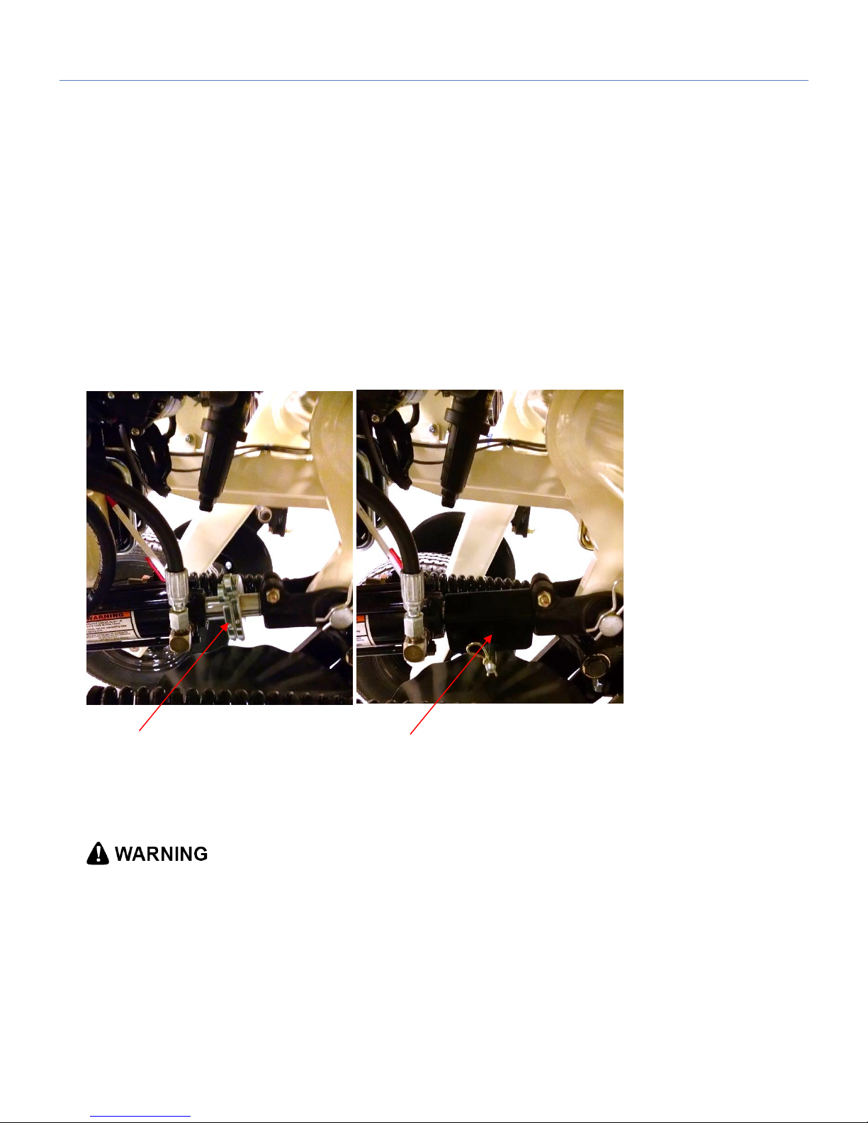
-Does the sampler only move one direction? Remove hydraulic cover and check LED’s on lower hyd
block DIN connections. Left is Up Sol, Right is down Sol.
3. pH electrodes not cleaning properly;
-check jets manually; are they both spraying, are they aligned?
-if pump not working, prime pump as outlined in pH Operations section; clean filter
-lengthen wash cycle (see Controller setup)
4. pH readings not agreeing with each other
-manually wash electrodes for several seconds; do they agree when clean?
-are both electrodes at same depth? Has one or both moved up into holder?
-perform 4 and 7 pH buffer solution test
5. pH readings taking too long to settle
-check soil/electrode contact; is i-Scan runner penetrating deep enough? Is crop residue entering
slot measurement area?
-Check movement of pH electrode parallel linkage; does it move freely and have full travel?
Page 58

Pub# OM20-U3-pH
6-22
-Inspect rear of shoe for mud buildup; could be preventing full electrode depth
-Are both electrodes bottomed out on electrode holder?
-Is the U3 running parallel to the ground? if tipped forward, electrodes may not contact soil correctly.
Also check that there is ample spring pressure on electrode holder.
 Loading...