

Page 1
Installation Guide
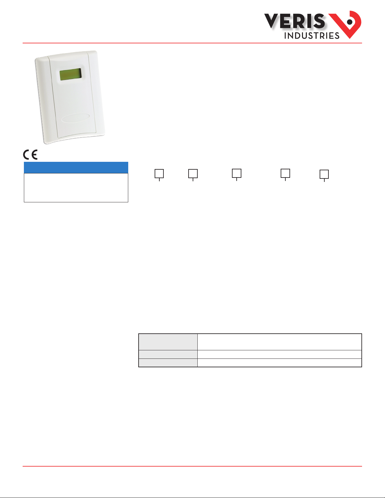
Air Quality
• This product is not intended for life or safety applications.
• Do not install this product in hazardous or classied locations.
• Read and understand the instructions before installing
this product.
• Turn off all power supplying equipment before working on it.
• The installer is responsible for conformance to all applicable codes.
No responsibility is assumed by Veris Industries for any consequences arising out of the
use of this material.
NOTICE
TW Series
Wall Mount Temperature Sensor
Product Overview
The TW Series temperature sensors are equipped with highly accuracy RTD/thermistor devices and an analog
output compatible with most building control systems. To maintain accurate functionality, keep all vents free of
dust, debris, etc. These units are warranted for a period of ve years.
Product Identification
Local Display
TW
L = LCD
X = No
Sensor Type
B = 100R platinum, RTD
C = 1k platinum, RTD
D = 10k T2, Thermistor
E = 2.2k, Thermistor
F = 3k, Thermistor
G = 10k CPC, Thermistor
H = 10k T3, Thermistor
J = 10k Dale, Thermistor
K = 10k w/11k shunt,Thermistor
M = 20k NTC, Thermistor
N = 1800 ohm, Thermistor
P = 10mV/°C, Linitemp
R = 10k US, Thermistor
S = 10k 3A221, Thermistor
T = 100k, Thermistor
U = 20k D Thermistor
W = 10k T2 high accuracy Thermistor
Y = 10kT3 high accuracy Thermistor
Z = 10k E1 Thermistor
Setpoint/Override
0 = None
1 = Override*
2 = 1k Setpoint
3 = 10k Setpoint
4 = 1k Setpoint with override
5 = 10k Setpoint with override
* Pushbutton over ride short circuits the RTD/thermis tor output.
Cal Certificate
0 = None
1 = 1 point Cal
2 = 2 point Cal
Housing Color
None = Cloud White
B = Black
TM
Specifications
Input Power
Temp Output
Ranges
Z206632-0A Page 1 of 3 ©2013 Veris Industries USA 800.354.8556 or +1.503.598.4564 / support@veris.com 06132
Alta Labs, E nercept, Ensp ector, Hawkeye, Trus tat, Aerospo nd, Veris, and th e Veris ‘V’ log o are tradema rks or registe red tradema rks of Veris Ind ustries, L. L.C. in the USA and /or other countri es.
Other companies’ trademarks are hereby acknowledged to belong to their respective owners.
4-20mA mode: loop powered 12-30VDC only, 30 mA max.
05 -/0 -10V mode: 12-3 0VDC/ 24VAC, 15mA max.
2-wire, loop powered 4-20mA or 3 -wire, 0- 5V /0-10VDC (switch selectable )
10° to 35°C (5 0° to 95°F) , 0° to 50°C ( 32° to 122°F ) (jumper selectable )
Page 2
Installation Guide
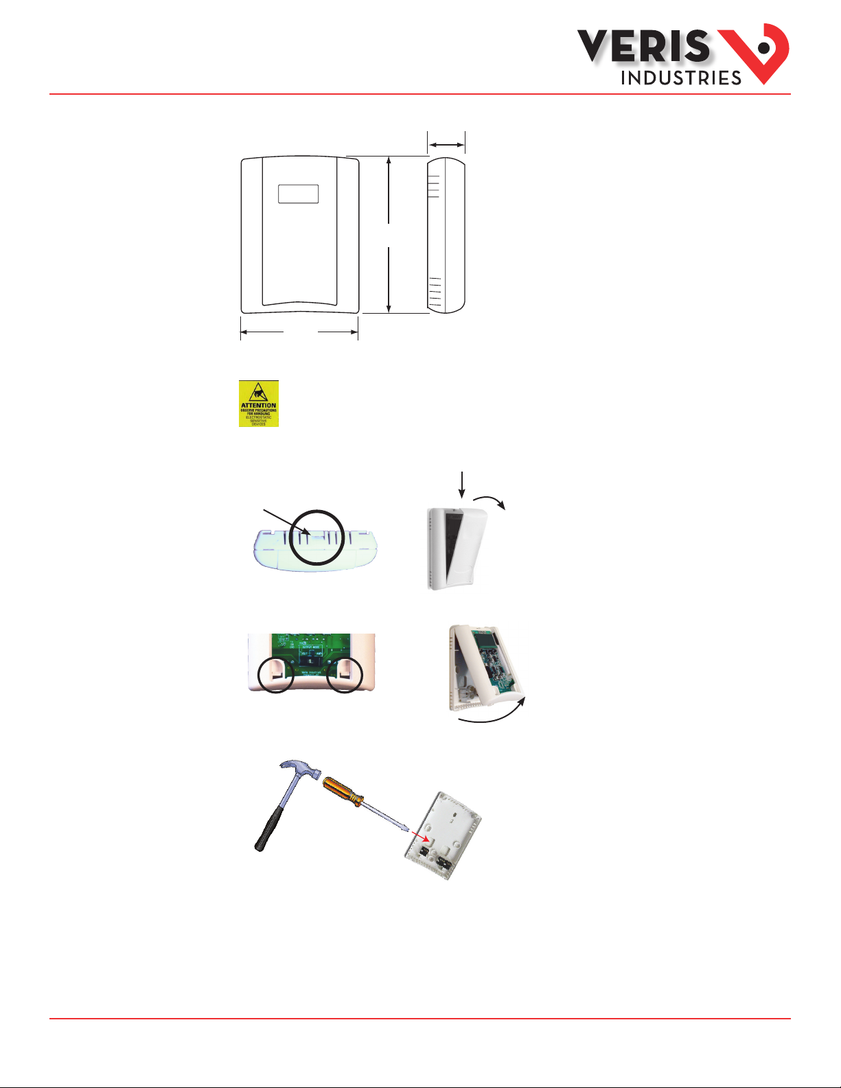
1.2"
(30 mm)
3.5"
(89 mm)
4.8"
(121 mm)
Air Quality
TWSeries
Dimensions
TM
Installation
Observe precautions for handling static sensitive
devices to avoid damage to the circuitry that
is not covered under the factory warranty.
1. Locate the tab at the top of the sensor housing. Using only the minimum required force, press this tab down and pull the cover
outward from the top. Set the cover aside.
Housing, Top View
Tab
2. Remove the backplate by unfastening the sensor from the bottom of the backplate and pivoting the sensor outward.
3. Punch out wire opening in the backplate.
4. Position the backplate vertically on the wall, 4½ feet (1.37 m) above the oor. Locate away from windows, vents, and other
sources of draft. If possible, do not mount on an external wall, as this might cause inaccurate temperature readings.
Z206632-0A Page 2 of 3 ©2013 Veris Industries USA 800.354.8556 or +1.503.598.4564 / support@veris.com 06132
Alta Labs, E nercept, Ensp ector, Hawkeye, Trus tat, Aerospo nd, Veris, and th e Veris ‘V’ log o are tradema rks or registe red tradema rks of Veris Ind ustries, L. L.C. in the USA and /or other countri es.
Other companies’ trademarks are hereby acknowledged to belong to their respective owners.
Page 3

Installation Guide
Air Quality
TWSeries
TM
Installation
(cont.)
5. Mount the backplate onto the wall using the screws provided.
Five screwholes available; use a
minimum of two for secure mounting.
6. Wire the backplate.
Current Output (2-Wire, 4-20 mA)
+
POWER SUPPLY
12-30 VDC
-
CONTROL SYSTEM
COMMON
-
T RETURN
RTD/THERMISTOR OVERRIDE
SETPOINT SLIDER
PWR (4-20 SEND)
T OUT (4-20 RTN)
RTD/THERMISTOR OVERRIDE
RTD/THERMISTOR OVERRIDE
SLIDER RIGHT
SLIDER LEFT
SLIDER WIPER
PWR
COMMON
Voltage Output (3-Wire, 0-5/0-10 V)
+
POWER SUPPLY
12-30 VDC/24 VAC
-
CONTROL SYSTEM
COMMON
-
T INPUT 0-10 V
RTD/THERMISTOR/OVERRIDE
SETPOINT SLIDER
T OUT
RTD/THERMISTOR/OVERRIDE
RTD/THERMISTOR/OVERRIDE
SLIDER RIGHT
SLIDER LEFT
SLIDER WIPER
7. Install the sensor onto the backplate and use the switch to select voltage or current output. Output selection must be correct
before applying power to the sensor.
OUTPUT SELECT
VOLTS
T RANGE
50-95(F)
10-35(C)
32-122(F)
0-50(C)
mA
T OUT
10V 5V
T SCALE
C F
8. When the installation is complete, replace the cover and snap it into position.
Z206632-0A Page 3 of 3 ©2013 Veris Industries USA 800.354.8556 or +1.503.598.4564 / support@veris.com 06132
Alta Labs, E nercept, Ensp ector, Hawkeye, Trus tat, Aerospo nd, Veris, and th e Veris ‘V’ log o are tradema rks or registe red tradema rks of Veris Ind ustries, L. L.C. in the USA and /or other countri es.
Other companies’ trademarks are hereby acknowledged to belong to their respective owners.
 Loading...