

Page 1
VERIS INDUSTRIES
™
POWER MONITORING
HAZARD OF ELECTRIC SHOCK, EXPLOSION, OR ARC FLASH
• Follow safe electrical work practices. See NFPA 70E in the USA, or applicable local codes.
• This equipment must only be installed and serviced by qualified electrical personnel.
• Read, understand and follow the instructions before installing this product.
• Turn off all power supplying equipment before working on or inside the equipment.
• Use a properly rated voltage sensing device to confirm power is off.
DO NOT DEPEND ON THIS PRODUCT FOR VOLTAGE INDICATION
• Only install this product on insulated conductors.
Failure to follow these instructions will result in death or serious injury.
DANGER
NOTICE
• This product is not intended for life or safety applications.
• Do not install this product in hazardous or classified locations.
• The installer is responsible for conformance to all applicable codes.
• Mount this product inside a suitable fire and electrical enclosure.
FCC PART 15 INFORMATION
NOTE: This equipment has been tested by the manufacturer and found
to comply with the limits for a class A digital device, pursuant to part
15 of the FCC Rules. These limits are designed to provide reasonable
protection against harmful interference when the equipment is
operated in a commercial environment. This equipment generates,
uses, and can radiate radio frequency energy and, if not installed and
used in accordance with the instruction manual, may cause harmful
interference to radio communications. Operation of this equipment in
a residential area is likely to cause harmful interference in which case
the user will be required to correct the interference at his own expense.
Modifications to this product without the express authorization of
Veris Industries nullify this statement.
Observe handling precautions for static sensitive
devices to avoid damage to the circuitry which
would not be covered under the factory warranty.
INSTALLATION GUIDE
H8126 - CB
H8126 - CB
N2 Communication Board for the
H81xx Energy Meter
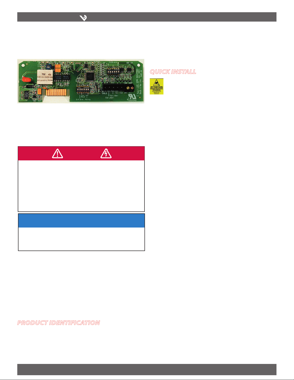
quIck Install
Disconnect power to the meter.1.
Set the DIP switches for appropriate network addressing.2.
Wire the communications terminals for 2-wire or 4-wire communication.3.
Disconnect power to the energy meter. Discharge static using an anti-static or 4.
grounding strap.
Still using the anti-static strap, install the H8126-CB into the slot in the energy 5.
meter until the board clicks into place.
Restore power to the meter.6.
Product IdentIfIcatIon
H8126-CB N2 Communication Board
Z2 03167- 0A PAGE 1 ©2009 Veris Industries USA 800.354.8556 or +1(0)503.598.4564 / support@veris.com 10092
Alta Labs, Enercep t, Enspector, Hawkeye, Trustat, Veris, and the Veris ‘ V’ logo are trademark s or registered tradema rks of Veris Industries, L.L .C. in the USA and/or othe r countries.
Page 2
VERIS INDUSTRIES
™
H8126-CB
ON
1 2 3 4 5 6
ON
1 2 3 4 5 6
1 2
TX RX
3
RX
4
TX
5
6
7
8
9 10
ALIVE
LITHIUM BATTERY
10
oPeratIon
The H8126-CB Energy Meter Communication Board is an optional field-installable
board for the H8163 Energy Meter, providing N2 communications capability. The
H8126-CB also enables the energy meter to provide true kW & kVAR demand
information.
The easy-to-install H8126-CB provides a simple, cost-effective way to network the
H8163 Energy Meter on the N2 bus.
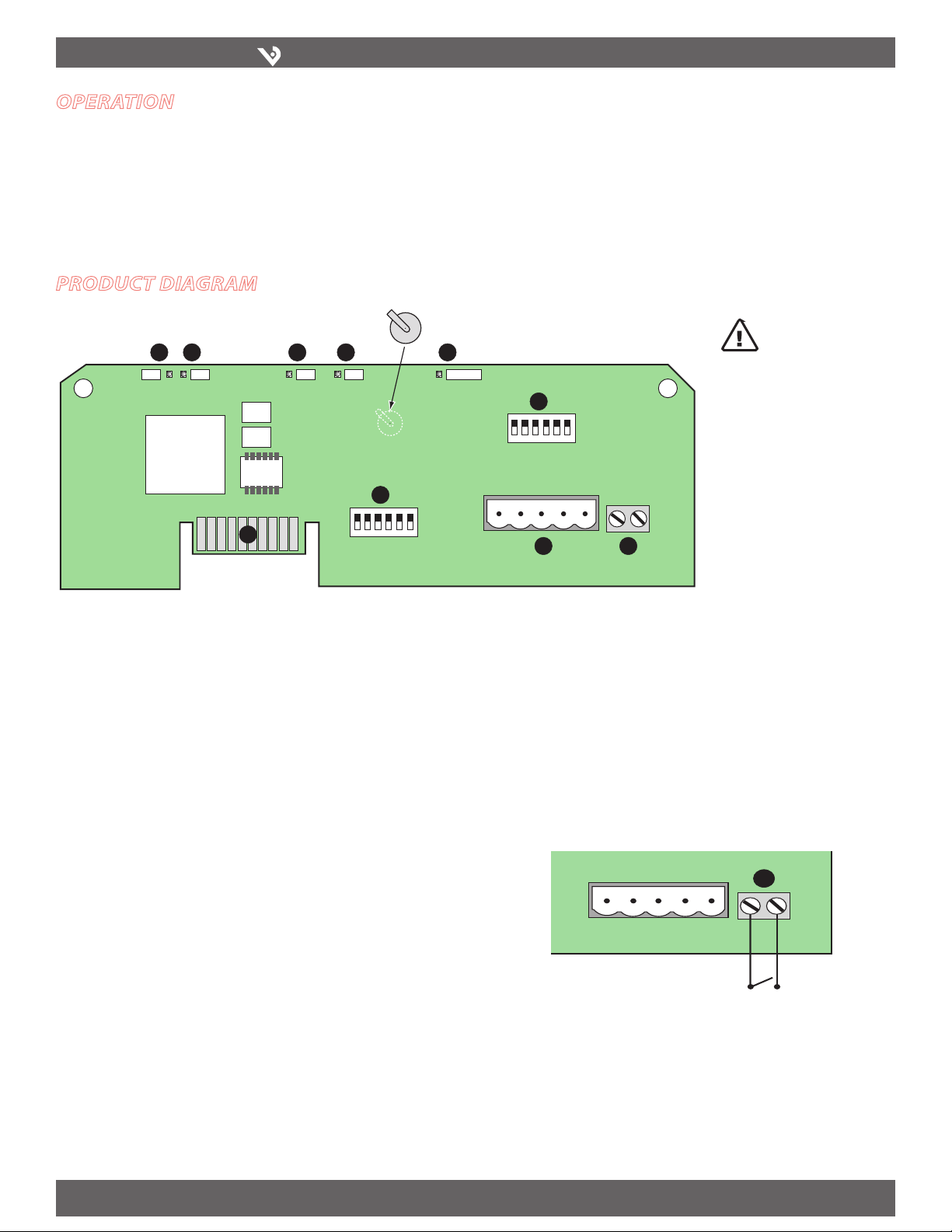
Product dIagram
INSTALLATION GUIDE
CAUTION! Danger of
explosion if battery is
incorrectly replaced.
Replace only with the
same or equivalent type
recommended by the
manufacturer. Dispose of
used batteries according
to the manufacturer’s
instructions.
RS-485 LED (TX):1. Red LED; blinks to indicate that the H8126-CB is transmitting
data to the master.
RS-485 LED (RX):2. Red LED; blinks to indicate that the H8126-CB is receiving data
from the master.
LED from Main Board (RX):3. Green LED; blinks to indicate that the H8126-CB is
receiving data from the main board.
LED from Main Board (TX):4. Green LED; blinks to indicate that the H8126-CB is
transmitting data to the main board.
“ALIVE” LED:5. Green LED; should blink once per second to indicate normal
operation of the H8126-CB.
N2 Network Address DIP Switches:6. Use these DIP switches to set the network
address for the H8126-CB. See the Settings table on page 3 for more information.
Connection to Energy Meter: Install the H8126-CB in the energy meter by
7.
inserting this connector into the connection slot at the top of the energy meter.
Communication DIP Switches:8. N2 factory default
RS-485 Communication Terminals: 9. Insert the RS-485 connector into these
terminals. See Wiring Diagrams on page 4 for instructions on wiring the connector
for 2-wire or 4-wire communications.
End of Demand Subinterval Terminal:10. Use this terminal as the input
connector for “end of demand interval” signal from the utility or other source. An
interposing isolated relay should be used as the dry contact for this
terminal, as pictured below. Do not apply voltage to this connection.
Z2 03167- 0A PAGE 2 ©2009 Veris Industries USA 800.354.8556 or +1(0)503.598.4564 / support@veris.com 10092
Alta Labs, Enercep t, Enspector, Hawkeye, Trustat, Veris, and the Veris ‘ V’ logo are trademark s or registered tradema rks of Veris Industries, L.L .C. in the USA and/or othe r countries.
Page 3
VERIS INDUSTRIES
™
H8126-CB
WiringBaud Parit
y
INSTALLATION GUIDE
InstallatIon
This section describes the communications settings you must make to the H8126-CB.
When daisy-chaining N2 devices, follow these guidelines:
Connect up to 63 H8126-CB devices on a single daisy chain. •
Each H8126-CB device on the daisy chain must have a unique address. •
Before connecting the H8126-CB to the RS-485 communication wires,
set the address according to directions on this page.
For RS-485 cables, use shielded, twisted-pair wire (Belden Cable 1120A or •
equivalent).
Terminate the last device on the daisy chain. If the H8126-CB is the last •
device in a daisy chain, terminate it to ensure reliable communication per
the RS-485 standard (120Ω nominal impedence).
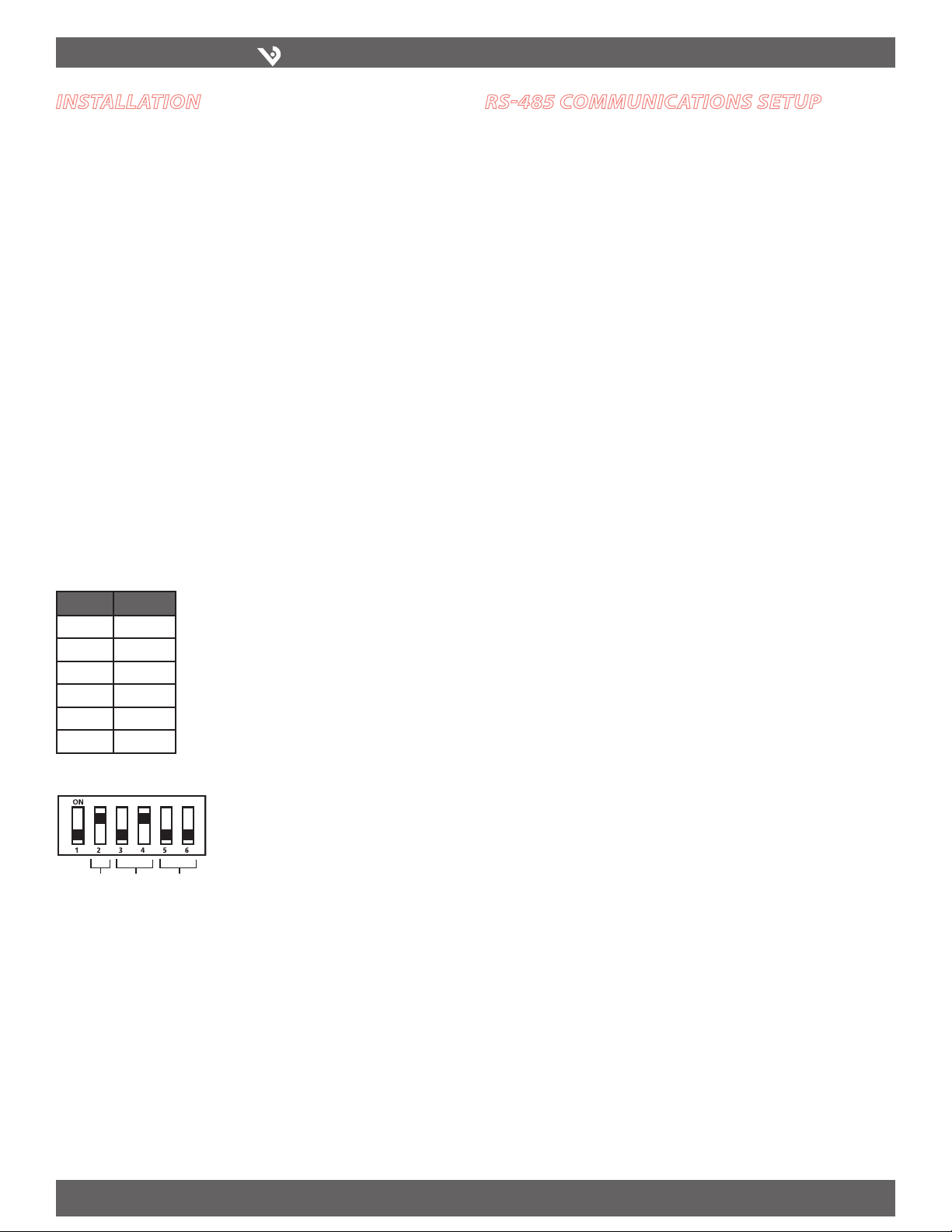
Selecting The Network Address – DIP Switches
Use the Network Address DIP switches to selec t the network address. Each H8126-CB
on a daisy chain must have a unique network address (from 1 to 63). Devices with the
same address will be unable to communicate.
Always set the address before you install the H8126-CB in the energy meter and
before you connect the energy meter to the daisy chain.
Each of the six DIP switches has a unique address value. The N2 Addressing section on
page 6 lists DIP switch positions for specific addresses.
rs-485 communIcatIons setuP
Wiring the Connector
Remove the 5-pin connector from the RS-485 communication terminals of the 1.
H8126-CB.
Wire the communications connector as shown on page 4 (2-wire communication).2.
Use a small, flat-blade screwdriver to tighten the connector screws.3.
Replace the connector on the RS-485 communication terminals of the H8126-CB.4.
If the H8126-CB is the last device in a daisy chain, terminate it to ensure reliable 5.
communication per the RS-485 standard (120Ω nominal impedence).
Network Address DIP Switch Values
Switch Value
1 1
2 2
3 4
4 8
5 16
6 32
Setting the Communication DIP Switches
The wiring type, baud rate, and paritycommunication DIP switches are factory set to
N2 specifications (9600 baud, no parity, 2-wire
communication).
Z2 03167- 0A PAGE 3 ©2009 Veris Industries USA 800.354.8556 or +1(0)503.598.4564 / support@veris.com 10092
Alta Labs, Enercep t, Enspector, Hawkeye, Trustat, Veris, and the Veris ‘ V’ logo are trademark s or registered tradema rks of Veris Industries, L.L .C. in the USA and/or othe r countries.
Page 4

VERIS INDUSTRIES
™
wIrIng dIagram
TX+
REF
N2+
N2–
TX–
REF
ON
1 2 3 4 5 6
ON
1 2 3 4 5 6
TX RX RX ALIVE
REF N2- N2+
TX+
REF
TX–
MASTER SLAVE
N2+
N2–
2-Wire Communications *
H8126-CB
INSTALLATION GUIDE
* If the H8126-CB is the last device in a daisy cha in, terminate it to ensure reliable commu nication
per the RS-485 standard (120Ω nominal impedence).
Z2 03167- 0A PAGE 4 ©2009 Veris Industries USA 800.354.8556 or +1(0)503.598.4564 / support@veris.com 100 92
Alta Labs, Enercep t, Enspector, Hawkeye, Trustat, Veris, and the Veris ‘ V’ logo are trademark s or registered tradema rks of Veris Industries, L.L .C. in the USA and/or othe r countries.
Page 5

VERIS INDUSTRIES
™
H8126-CB
SLOTS
TOP
COMMS BOARD
BATTERY
CONNECTORS
CONNECTION
SLOTS
Observe handling precautions for static sensitive
devices to avoid damage to the circuitry which
would not be covered under the factory warranty.
ON
1 2
TX RX
3
RX
4
TX
5
6
ALIVE
D5 D6 D13 D14 D1
InstallIng the cb In the h8163 energy meter
Complete the Communications Setup and Wiring instructions before
installing the board inside the meter.
The H8126-CB is designed as a plug-and-play accessory for the H8163 energy meter.
Follow these instructions to install the H8126-CB into the energy meter.
Turn off all power to the energy meter and the equipment in which it is installed. 1.
a. Remove the voltage terminal from the energy meter and all fuses.
b. Always use a properly rated voltage sensing device to confirm that power
is off.
To discharge static, follow the instructions that come with your anti-static or 2.
grounding strap.
NOTE: We recommend using an anti-static or grounding strap until you have
completed installation of the H8126-CB.
Slide the H8126-CB into the slot in the energy meter. The sides of the H8126-3.
CB slide down into the channels on either side of the energy meter. When the
male connection to the energy meter clicks into place, the H8126-CB is properly
installed.
INSTALLATION GUIDE
Insert the communication terminal onto the RS-485 communication terminals.4.
If the demand subinterval feature is used, wire into the end of demand subinterval 5.
terminal.
Replace the voltage terminal into the energy meter.6.
troubleshootIng
If communications are not working properly, first check that the board is properly
seated in its slot in the energy meter, and that the connector has clicked into place in
the connection slot on the meter.
There are five LEDs that indicate various types of communication.
During normal operation, all five LEDs will blink regularly. When an error occurs, the
abnormal LED will help determine where that error is.
LED
Number
1 RS-485 (TX) Not blinking No communication from the H8163 to the master.
2 RS-485 (RX) Not blinking No communication from the master. N2- and N2+ may be reversed. Correct the wiring.
3 From main board (RX) Not blinking Main board not responding. Contact customer support for assistance.
4 From main board (TX) Not blinking but
5 “Alive” status Steadily lit Internal communications board error. Contact customer support for assistance.
Z2 03167- 0A PAGE 5 ©2009 Veris Industries USA 800.354.8556 or +1(0)503.598.4564 / support@veris.com 100 92
Alta Labs, Enercep t, Enspector, Hawkeye, Trustat, Veris, and the Veris ‘ V’ logo are trademark s or registered tradema rks of Veris Industries, L.L .C. in the USA and/or othe r countries.
LED Description Abnormal Operation Solution
“Alive” LED is blinking
· Check the wiring; N2- and N2+ may be reversed. Correc t the wiring.
· If RX is blinking, verify the DIP switch address, parity, baud rate, and wire type.
Internal communications board error. Contact customer support for assistance.
Page 6

VERIS INDUSTRIES
™
H8126-CB
32
33 34 35 36 37 38 39 40 41 42 43
44 45 46 47 48 49 50 51 52 53 54
55 56 57 58 59 60 61 62 63
0
11
22 23 24 25 26 27 28 29 30 31
12 13 14 15 16 17 18 19 20 21
1 234 5 678 910
INSTALLATION GUIDE
n2 addressIng
The figure below illustrates the switch settings, using the Network Address DIP switches, for each Network address. See “Selecting the network Address - NETWORK ADDRESS
DIP SWITCHES” on page 3 for instructions on setting the switches.
Z2 03167- 0A PAGE 6 ©2009 Veris Industries USA 800.354.8556 or +1(0)503.598.4564 / support@veris.com 100 92
Alta Labs, Enercep t, Enspector, Hawkeye, Trustat, Veris, and the Veris ‘ V’ logo are trademark s or registered tradema rks of Veris Industries, L.L .C. in the USA and/or othe r countries.
Page 7

VERIS INDUSTRIES
™
H8126-CB
INSTALLATION GUIDE
n2 objects
NPT NPA OR WR Units Range Description
AI 1 Y Y kWh 0-33554432 Consumption
AI 2 Y Y kW 0 -10 0 .6 Power
AI 3 Y Y k VAR 0 -10 0. 6 Reactive Power
AI 4 Y Y k VA 0 -10 0. 6 Apparent Power
AI 5 Y Y Vol ts 0 -1. 0 Total Power Factor
AI 6 Y Y Vol ts 5-528 Average Voltage L-L
AI 7 Y Y Amps 3-30 5 Average Voltage L-N
AI 8 Y Y kW 1 -110 Average Current
AI 9 Y Y kW 0 -33.5 Real Power, Phase A
AI 10 Y Y kW 0 -33.5 Real Power, Phase B
AI 11 Y Y kW 0 -33.5 Real Power, Phase C
AI 12 Y Y 0 -1.0 Power Factor, phase A
AI 13 Y Y 0 -1.0 Power Factor, phase B
AI 14 Y Y 0-1 .0 Power Factor, phase C
AI 15 Y Y Vo lts 5-528 Voltage, phase A-B
AI 16 Y Y Vo lts 5-528 Voltage, phase B-C
AI 17 Y Y Volt s 5-528 Voltage, phase A-C
AI 18 Y Y Vo lts 3-30 5 Voltage, phase A-N
AI 19 Y Y Vo lts 3-30 5 Voltage, phase B-N
AI 20 Y Y Vo lts 3-30 5 Voltage, phase C-N
AI 21 Y Y Amps 1-110 Current, phase A
AI 22 Y Y Amps 1-11 0 Current, phase B
AI 23 Y Y Amps 1-11 0 Current, phase C
AI 24 Y Y kW Demand 0-1 00 .6 Present Demand Subinter val (the currently accumulating subinterval demand; constantly
changing)
AI 25 Y Y kW Demand 0 -10 0. 6 Present Demand (updated at the end of every subinterval; the average of the previous N
subintervals [ADI 17])
AI 26 Y Y kW Demand 0 -10 0.6 Peak Demand (highest demand value [AI 25] that has occured; a nonvolatile point)
AI 27 Y Y kVAR Demand 0 -10 0. 6 Present kVAR Subinterval (the currently accumulating subinterval kVAR; constantly changing)
AI 28 Y Y kVAR Demand 0-1 00 .6 Present kVAR (updated at the end of every subinterval; the average of the previous N subintervals
[ADI 17])
AI 29 Y Y kVAR Demand 0 -3072 Peak kVAR (highest kVAR value [ADI 28] that has occured; a nonvolatile point)
BI 1 Y N kWh 100A:0.0078125/count
200A:0.015625/count
800A:0.0625/count
1600:0.125/count
300A:0.03125/count
400A:0.03125/count
2400A:0.25/count
Intended as an accumulator (ACM) type. Do not read as binary status.
Z2 03167- 0A PAGE 7 ©2009 Veris Industries USA 800.354.8556 or +1(0)503.598.4564 / support@veris.com 100 92
Alta Labs, Enercep t, Enspector, Hawkeye, Trustat, Veris, and the Veris ‘ V’ logo are trademark s or registered tradema rks of Veris Industries, L.L .C. in the USA and/or othe r countries.
Page 8

VERIS INDUSTRIES
™
H8126-CB
NPT NPA OR WR Units Range Description
ADI 1 Y N kWh 0-65535 LSW of kWh accumulator. Lower 16 bits of kWh.
ADI 2 Y N kWh 0-65535 MSW of kWh accumulator. Upper 16 bits of kWh.
ADI 3 Y N 0-65535 Phase Loss. Latching Register (bit mapped):
Bit 0: phase A (unpredictable results on phase A)
Bit 1: phase B
Bit 2: phase C
ADI 4 Y N 0-65535 Date/Time Month 1-12 (LSB) Day 1-31 (MSB)
ADI 5 Y N 0-65535 Date/Time Year 0-1999 (LSB) Hour 0-23 (MSB)
ADI 6 Y N 0-65535 Date/Time Minutes 0-59 (LSB) Seconds 0-59 (MSB)
ADI 7 Y N Secs 0-65535 High Alarm Delay: sets the minimum time a signal must remain in state before the alarm is set
(default is 30 sec)
ADI 8 Y N Secs 0-65535 High Warning Delay: sets the minimum time a signal must remain in state before the warning is
set (default is 30 sec)
ADI 9 Y N Secs 0-65535 Low Warning Delay: sets the minimum time a signal must remain in state before the warning is
set (default is 30 sec)
ADI 10 Y N Secs 0-65535 Low Alarm Delay: sets the minimum time a signal must remain in state before the alarm is set
(default is 30 sec)
ADI 11 Y N 0-65535 Count of kWh resets: the number of times the kWh accumulator has been reset (rolls over at
65535)
ADI 12 Y N 0-65535 Count of Peak Demand Resets: the number of times the peak demand (ADI 26) has been reset
(rolls over at 65535)
ADI 13 Y N 0-65535 Count of Peak kVAR Resets: the number of times the kVAR (ADI 29) has been reset (rolls over at
65535)
ADI 14 Y N 0-65535 Count of Elapsed Subintervals: the number of subintervals that have elapsed. Since the demand
(AI 25) is updated every subinterval, this register indicates whether an identical value in AI 25 is
actually the same demand interval or a new interval with a steady load.
ADI 15 Y N 0-65535 Number of Readings in Present Subinterval: the number of readings taken in the present
subinterval (AI 24 and AI 27). This register acts as an unsigned integer and will increment every
200 msec (5 times per sec).
ADI 16 Y N 0-65535 Subinterval Length: sets the length of a subinterval. Value = num. of seconds * 5. For sync-to-
comms or sync-to-demand-reset-input (hardware signal), set this to zero.
ADI 17 Y N 1- 6 Number of Subintervals per Demand Interval: sets the number of subintervals that make a single
demand interval. Valid values are 1 to 6. For block demand, set this to 1. Default is 6.
ADI 18 Y N 100-2400 CT Size
ADI 19 Y N 1-3 CT Number
ADI 20 Y N 0-65535 Count of Phase Losses: number of phase losses on any phase (rolls over at 65535)
ADI 21 Y N 0-65535 Phase Loss Timestamp, Month 1-12 (LSB) Day 1-31 (MSB)
ADI 22 Y N 0-65535 Phase Loss Timestamp, Year 0-199 (LSB) Hour 1-24 (MSB)
ADI 23 Y N 0-65535 Phase Loss Timestamp, Minutes 0-59 (LSB) Seconds 0-59 (MSB)
ADI 24 Y N 0-65535 Last Restart Timestamp, Month 1-12 (LSB) Day 1-31 (MSB)
ADI 25 Y N 0-65535 Last Restart Timestamp, Year 0-199 (LSB) Hour 1-24 (MSB)
ADI 26 Y N 0-65535 Last Restart Timestamp, Minutes 0-59 (LSB) Seconds 0-59 (MSB)
ADI 27 Y N 0-65535 Last kWh Reset Timestamp, Month 1-12 (LSB) Day 1-31 (MSB)
ADI 28 Y N 0-65535 Last kWh Reset Timestamp, Year 0-199 (LSB) Hour 1-24 (MSB)
ADI 29 Y N 0-65535 Last kWh Reset Timestamp, Minutes 0-59 (LSB) Seconds 0-59 (MSB)
INSTALLATION GUIDE
Z2 03167- 0A PAGE 8 ©2009 Veris Industries USA 800.354.8556 or +1(0)503.598.4564 / support@veris.com 100 92
Alta Labs, Enercep t, Enspector, Hawkeye, Trustat, Veris, and the Veris ‘ V’ logo are trademark s or registered tradema rks of Veris Industries, L.L .C. in the USA and/or othe r countries.
Page 9

VERIS INDUSTRIES
™
H8126-CB
NPT NPA OR WR Units Range Description
ADI 30 Y N 0-65535 Firmware Version
ADI 31 Y N 0-65535 Firmware Revision
ADI 32 Y N 0-65535 Serial Number LSW
ADI 33 Y N 0-65535 Serial Number MSW
BO 1 Y N 0=NA
1=Reset kWh
accumulator
BO 2 Y N 0=NA
1=Reset peak demand
BO 3 Y N 0=NA
1=Reset peak kVAR
BO 4 Y N 0=NA
1=Begin new demand
subinterval
BO 5 Y N 0=NA
1=Reset phase loss
register
INSTALLATION GUIDE
Legend
OR Object can be overwritted
WR Object can be written
Range The AI ranges are based on a 3-phase 480V system with 100A CTs
NPT Network point type
NPA Network point address
Units Engineering units
Description Point description
Supported N2 Commands
0/0 Time update message
0/4 Poll without acknowledge message
0/5 Poll with acknowledge message
1/1 Read AI command
1/6 Read ADI command
1/2 Read BI command
1/4 Read BO command
2/1 Write AI command
2/2 Write BI command
2/4 Write BO command
7/2/01 Override AI command
7/2/06 Override ADI command
7/2/04 Override BO command
7/3/01 Override release AI request
7/3/06 Override release ADI request
7/3/02 Override release BI request
7/3/04 Override release BO request
F Identify device type command
Z2 03167- 0A PAGE 9 ©2009 Veris Industries USA 800.354.8556 or +1(0)503.598.4564 / support@veris.com 100 92
Alta Labs, Enercep t, Enspector, Hawkeye, Trustat, Veris, and the Veris ‘ V’ logo are trademark s or registered tradema rks of Veris Industries, L.L .C. in the USA and/or othe r countries.
Page 10

VERIS INDUSTRIES
™
H8126-CB
demand comPutatIon, Internal
algorIthm
The H8163 energy meter records every kW/kVAR reading, as well as a count of the
number of these readings. These readings are recorded every 200 msec (5 Hz). The
meter then computes the present subinterval demand as:
Average kW/kVAR = accumulated kW/kVAR / number of readings
This present subinterval demand can be read at registers AI 25 (kW) and AI 28 (kVAR).
A subinterval may be terminated in three ways:
Write to BO.1.
Detection of the hardware signal (interval reset).2.
Set the subinterval length (register ADI 16) to a nonzero value. The subinterval 3.
will end if the count of the number of kW readings equals or exceeds the nonzero
subinterval length.
While there are three ways to end a subinterval, it is expected that applications will
use only one of them.
The maximum valid subinterval length is 65535 readings, which corresponds to 3
hours, 38 minutes, 27.2 seconds. When the device records the 65536th reading, the
subinterval reading counter will roll over. This condition is detected and causes the
subinterval to end. The next subinterval will begin on the next reading. In normal
operation, a subinterval should not last longer than 1 hour.
INSTALLATION GUIDE
When a subinterval ends, the average kW/kVAR during that subinterval (accumulated
kW/kVAR readings divided by the number of readings) is added to a 6 value fifo list
of the 6 most recent subintervals. The kW/kVAR accumulator and count of kW/kVAR
readings are cleared to zero, a new subinter val begins, and the count of subintervals
(ADI 14) increments. The present demand is recomputed by averaging the first
N elements of the fifo, where N is the value in register ADI 17. If the new present
demand is higher than the stored peak demand, then the peak demand is updated to
the new present demand.
Z2 03167- 0A PAGE 10 ©2009 Veris Industries USA 800.354.8556 or +1(0)503.598.4564 / support@veris.com 10 092
Alta Labs, Enercep t, Enspector, Hawkeye, Trustat, Veris, and the Veris ‘ V’ logo are trademark s or registered tradema rks of Veris Industries, L.L .C. in the USA and/or othe r countries.
 Loading...