

Page 1
TM
the user will be required to correct the interference at his own expense.
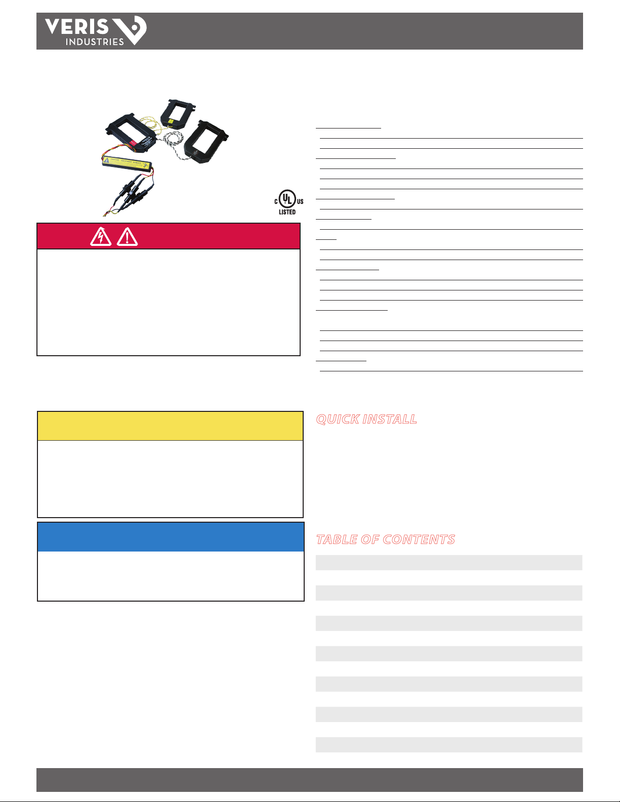
ENERCEPT ™ H8035/H8036
Networked Power Transducer (Modbus RTU)
Installer’s Specifications
Measurement A ccuracy:
Syste m Accuracy ±1% of reading from 10% to 100% of the rated current *
Type of Measurement One or three phase AC system
Input Voltage Characteristics:
Measured AC Voltage 208-480 VAC
POWER MONITORING
US Patent No. 6,373,238
DANGER
HAZARD OF ELECTRIC SHOCK, EXPLOSION, OR ARC FLASH
• Follow safe electrical work practices. See NFPA 70E in the USA, or applicable local codes.
• This equipment must only be installed and serviced by qualified electrical personnel.
• Read, understand and follow the instructions before installing this product.
• Turn off all power supplying equipment before working on or inside the equipment.
• Use a properly rated voltage sensing device to confirm power is off.
DO NOT DEPEND ON THIS PRODUCT FOR VOLTAGE INDICATION
• Only install this product on insulated conductors.
Failure to follow these instructions will result in death or serious injury.
A qualied person is one who has skills and knowledge related to the construction and
operation of this electrical equipment and the installation, and has received safety
training to recognize and avoid the hazards involved. NEC2009 Article 100
No responsibility is assumed by Veris Industries for any consequences arising out of the
use of this material.
CAUTION
RISK OF EQUIPMENT DAMAGE
• Enercept meters are rated for use at 50-60Hz. Do not connect this product to circuits with
high harmonic energy, such as Variable Speed Drives (a.k.a. Variable Frequency Drives,
Adjustable Frequency Drives) or similar sources, as these may permanently damage the
product.
Failure to follow these instructions can result in overheating and permanent
equipment damage.
Frequency Range 50/60 Hz
Fuses 1/2A, 600VAC, 200 kAIC
Input Current Characteristics:
Maximum Primary Current 100, 300, 400, 800, 1600, or 2400 A, continuous p er phase**
Meter Current Draw:
Maximum 60 mA AC
Output:
Modbus RTU Protocol RS-485, 2-wire plus common
Baud Rate 9600
Mechanical Conditions:
CT Case Iso lation 600 VAC
Internal Isolation 2000 VAC RMS
Terminal Block Screw Torque 0.37 ft-lb (0.5 N·m) min.; 0.44 ft-lb (0.6 N·m) max.
Environmental Conditions:
Operating Temperature Range 2400 A model only: 0° to 50°C (32° to 122°F)
all other models: 0° to 60°C (32° to 140°F)
Storage Temperature Range -40° to 70°C (-40° to 15 8°F)
Operating Humidity Range <95% RH non-condensing
Agency Approvals:
US and Canada (cULus) UL508 (open ty pe device)
* Meter accuracy specied with conduc tors centered in the CT window.
** For amperages greater than 2400A, see App Note VN19, www.veris.com/applicationnotes.aspx
QUICK INSTALL
Disconnect and lock out power before installation.
1. Set the address switches located on the bottom of the CT.
2. Connect the voltage leads to the source to be monitored.
3. Snap the CT onto the conductor (observe color matching).
4. Connect the Modbus wires (observe polarity).
INSTALLATION GUIDE
NOTICE
• This product is not intended for life or safety applications.
• Do not install this product in hazardous or classified locations.
• The installer is responsible for conformance to all applicable codes.
• Mount this product inside a suitable fire and electrical enclosure.
FCC PART 15 INFORMATION
NOTE: This equipment has been tested by the manufacturer and found
to comply with the limits for a class A digital device, pursuant to part
15 of the FCC Rules. These limits are designed to provide reasonable
protection against harmful interference when the equipment is
operated in a commercial environment. This equipment generates,
uses, and can radiate radio frequency energy and, if not installed and
used in accordance with the instruction manual, may cause harmful
interference to radio communications. Operation of this equipment in
a residential area is likely to cause harmful interference in which case
Modifications to this product without the express authorization of
Veris Industries nullify this statement.
For use in a Pollu tion Degree 2 or bet ter environment only. A Pollut ion Degree 2 environme nt must
control conductive pollution and the possibility of condensation or high humidity. Consider the
enclosure, t he correct use of ven tilation, thermal pro perties of the equ ipment, and the relatio nship
with the env ironment. Installat ion category: CAT II or C AT III
Z201686-0N PAGE 1 ©2012 Veris Industries USA 800.354.8556 or +1.503.598.4564 / support@veris.com 08122
Alta Labs, Enercep t, Enspector, Hawkeye, Trustat, Veris, and the Veris ‘ V’ logo are trademark s or registered tradema rks of Veris Industries, L.L .C. in the USA and /or other count ries.
TABLE OF CONTENTS
Quick Install 1
Operation 2
Product Identication 2
Dimensions 2
Product Diagram 2
Installation 3
Wiring 4
Data Outputs 4
Address Setup 5
Modbus Register Addressing 6
Using Integer Data Types 8
Notes 10
Troubleshooting 10
Page 2
H8035/H8036
TM
INSTALLATION GUIDE
OPERATION
The H8035 and H8036 three-phase power transducers monitor energy parameters
from aggregate kW (real power) and kWh (consumption) to power factor per phase.
Integration of electronics lowers hardware and installation costs. The sensors
automatically detect phase reversal, so CT load orientation is not a concern. The CTs
and electronics are calibrated as a set, so it is necessary to color-match the CTs and
voltage leads when installing. These devices monitor up to 63 loads at a time on a
single RS-485 drop.
With two platforms to choose from (H8035 Basic/Energy Only or H8036 Enhanced
Data Stream), the applications for these devices are diverse, including aggregate
billing, tenant monitoring, energy management, performance contracting, demand
limiting and cooling plant optimization.
PRODUCT IDENTIFICATION
Modbus Enhanced Data Stream Power Transducers*
MODEL MAX. AMPS CT SIZE
H8036-0100-2 100 SMALL
H8036-0300-2 300 SMALL
H8036-0400-3 400 MEDIUM
H8036-0800-3 800 MEDIUM
H8036-0800-4 800 LARGE
H8036-1600-4 1600 LARGE
H8036-2400-4 2400 LARGE
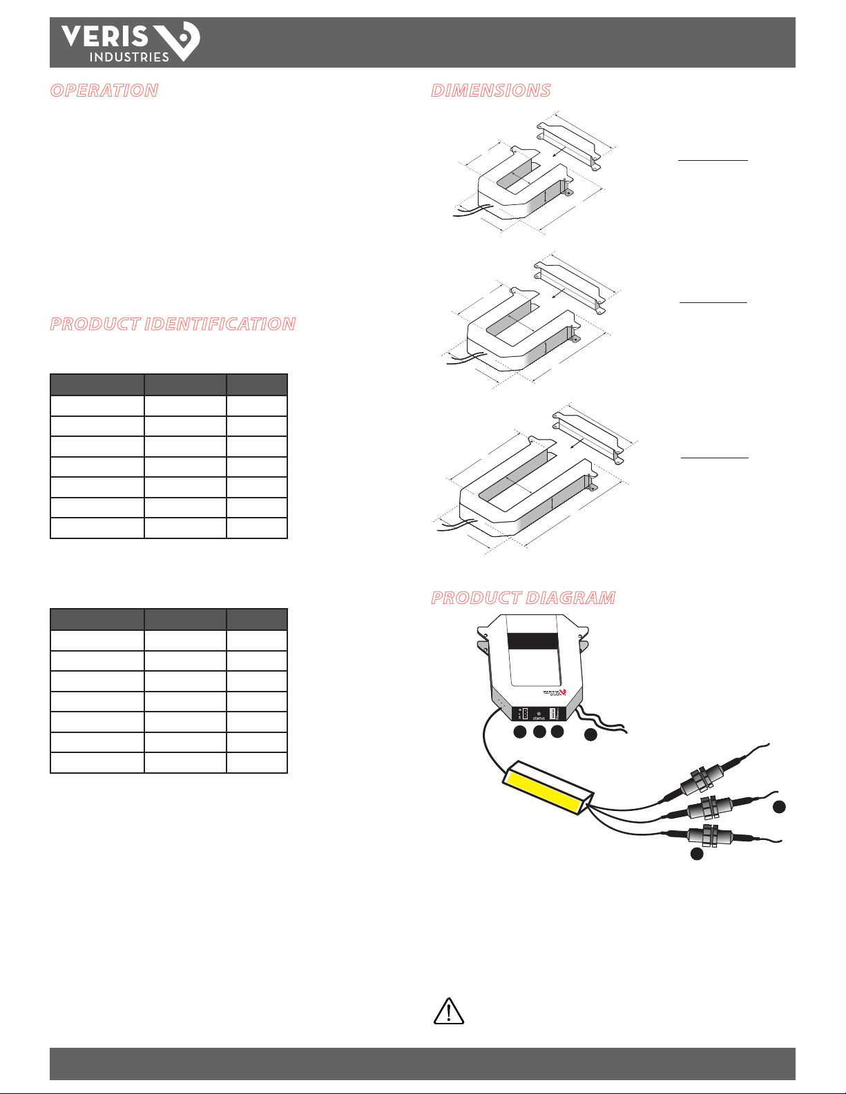
DIMENSIONS
B
C
A
B
C
A
B
C
A
F
SMALL
100/300 Amp
A = 3.8" (96 mm)
D
E
F
B = 1.2" (30 mm)
C = 1.3" (31 mm)
D = 1.2" (30 mm)
E = 4.0" (100 mm)
F = 4.8" (121 mm)
MEDIUM
400/800 Amp
A = 4.9" (125 mm)
D
E
F
B = 2.9" (73 mm)
C = 2.5" (62 mm)
D = 1.2" (30 mm)
E = 5.2" (132 mm)
F = 6.0" (151 mm)
LARGE
800/1600/2400 Amp
A = 4.9" (125 mm)
D
E
B = 5.5" (139 mm)
C = 2.5" (62 mm)
D = 1.2" (30 mm)
E = 7.9" (201 mm)
F = 6.0" (151 mm)
*H8036 models work with H8920-1 LON nodes
Modbus Basic Power Transducers*
MODEL MAX. AMPS CT SIZE
H8035-0100-2 100 SMALL
H8035-0300-2 300 SMALL
H8035-0400-3 400 MEDIUM
H8035-0800-3 800 MEDIUM
H8035-0800-4 800 LARGE
H8035-1600-4 1600 LARGE
H8035-2400-4 2400 LARGE
*H8035 models work with H8920-5 LON nodes
PRODUCT DIAGRAM
®
Enercept
5
4
3
1. Voltage leads
2. Fuses
3. Modbus connector
4. Status LED: Blink codes: slow green for normal operation; slow red for incorrect
wiring or low power factor (less than 0.5); fast red for maximum current exceeded.
5. Modbus address switches
6
2
1
6. External CTs: Permanently attached; do not disconnect or use with other power
transducers.
Color match CTs and voltage leads! Example: clamp the
red labeled CT around the power conductor connected to
the red voltage wire.
Z201686-0N PAGE 2 ©2012 Veris Industries USA 800.354.8556 or +1.503.598.4564 / support@veris.com 08122
Alta Labs, Enercep t, Enspector, Hawkeye, Trustat, Veris, and the Veris ‘ V’ logo are trademark s or registered tradema rks of Veris Industries, L.L .C. in the USA and /or other count ries.
Page 3
H8035/H8036
Wire tie
SHIELD
SHIELD
S
S
SHIELD
120Ω
Terminator
TM
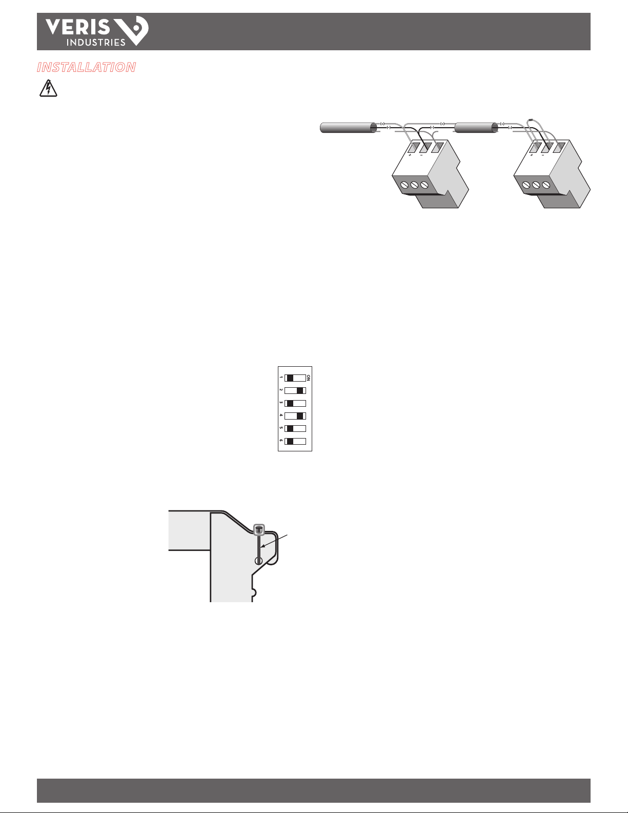
INSTALLATION
Disconnect and lock out power before installation.
The Enercept meter, including the current transformers (CTs), voltage connection
fuses, and fuse pack, is permitted within electrical distribution equipment
including but not limited to panelboards, switchboards, motor control centers, and
transformers. Carefully review the equipment in which the Enercept meter will
be installed. Consider the following installation conditions during the installation
process:
• Review the equipment enclosure for ventilation openings. Wires will cross
many of these openings in a normal installation, however, do not install
the Enercept where it will substantially block ventilation openings in the
enclosure.
• The Enercept meter and the wiring installed within a wiring space
or gutter should not exceed 75 percent cross sectional ll at the
Enercept meter parts as addressed in the NEC. Improper installation of
Enercept meter in the wire gut ter of equipment may aect the thermal
performance of the equipment.
• Consider the arrangement of CTs within the equipment to ensure the
correct bending radius of conductors.
• Review the arrangement and location of the CTs within the equipment.
Use appropriate support for the CT to prevent undue strain on the
conductor.
ADDRESS
1. Choose a unique address and set the switches for that address as
shown in the Address Selec tion Switches section. Only addresses 1
to 63 can be used.
2. Connect the voltage leads to the phase conductors at a location that
is not normally turned o. Connect voltage leads on the Line side
of the conductor to ensure constant power to the Enercept. For a
3-phase system, connect the red lead to phase A, black to phase B, and yellow to
phase C. See the Wiring section on the following page.
1
2
4
8
16
32
INSTALLATION GUIDE
4. Remove the terminal block and attach the RS-485 wires. Observe (+), (-), and
Shield polarity. Insulate any exposed wiring.
5. For information regarding software setup, see the Modbus protocol specications
available at www.veris.com/Modbus/.
6. Check power reading (these calculations are approximations only).
Expected power:
kW = Volts x Amps x 1.732 x PF / 1000
kW = Horsepower x 0.746
3. Snap the CT onto the conductor.
Connect CTs to the correspondingly
colored voltage leads. If the
application can exceed 20 times the
rated CT current, use wire ties to
secure the I-bar to the CT housing.
This CT automatically detects phase
reversal, so CT load orientation is not
important.
Z201686-0N PAGE 3 ©2012 Veris Industries USA 800.354.8556 or +1.503.598.4564 / support@veris.com 08122
Alta Labs, Enercep t, Enspector, Hawkeye, Trustat, Veris, and the Veris ‘ V’ logo are trademark s or registered tradema rks of Veris Industries, L.L .C. in the USA and /or other count ries.
Page 4

H8035/H8036
TM
INSTALLATION GUIDE
WIRING
ØB
ØA
ØC
120
ØB
Neutral
120
ØA
Typical 208/480 VAC 3Ø, 3- or 4- Wire Installation
Typical 240/120 VAC 1Ø, 3-Wire Installation
MODBUS RS-485 LINE
MODBUS RS-485 LINE
DATA OUTPUTS
H8035
kWh, consumption
Reset kWh
kW, demand
H8036
kWh, consumption
kW, real power
kVAR, reactive power
kVA, apparent power
Power fac tor
Average real power
Minimum real power
Maximum real power
Voltage, line-to-line
Voltage, line-to-neutral
Amps, average current
kW, real power ØA
kW, real power ØB
kW, real power ØC
Power factor ØA
Power factor ØB
Power factor ØC
Voltage, ØA to ØB
Voltage, ØB to ØC
Voltage, ØAto ØC
Voltage, ØA to Neutral
Voltage, ØB to Neutral
Voltage, ØC to Neutral
Amps, Current ØA
Amps, Current ØB
Amps, Current ØC
To additional MODBUS Devices
Typical 277 VAC 1Ø, 2-Wire Installation
Neutral
277
ØA
MODBUS RS-485 LINE
To additional MODBUS Devices
Note: The Enercept cannot communicate on the net work bus without power.
Therefore, it is best to connect the voltage lea ds ahead of switching devices.
Z201686-0N PAGE 4 ©2012 Veris Industries USA 800.354.8556 or +1.503.598.4564 / support@veris.com 08122
Alta Labs, Enercep t, Enspector, Hawkeye, Trustat, Veris, and the Veris ‘ V’ logo are trademark s or registered tradema rks of Veris Industries, L.L .C. in the USA and /or other count ries.
Page 5

H8035/H8036
TM
INSTALLATION GUIDE
ADDRESS SETUP
Set these switches to assign a unique address before connecting the device to the Modbus RS-485 line. Each Modbus device must have a unique address. If two devices are
given the same address, neither device will be able to communicate.
Z201686-0N PAGE 5 ©2012 Veris Industries USA 800.354.8556 or +1.503.598.4564 / support@veris.com 08122
Alta Labs, Enercep t, Enspector, Hawkeye, Trustat, Veris, and the Veris ‘ V’ logo are trademark s or registered tradema rks of Veris Industries, L.L .C. in the USA and /or other count ries.
Page 6

H8035/H8036
TM
INSTALLATION GUIDE
MODBUS REGISTER ADDRESSING
This table lists the addressed assigned to each data point. Registers are read MostSignicant Byte (MSB) rst. 32 bit oating point values are encoded per IEEE Standard 754.
For oating point format variables, each data point appears twice because two 16-bit addresses are required to hold a 32-bit oat value. The 16 bit Most Signicant Word
(MSW) is in the lower address of the register pair, while the least Signicant Word (LSW) is in the upper address.
Modbus RTU function codes suppor ted: 3=read holding registers; 6=preset single register; 17=report Slave I.D.
Quick Reference of the Most Common Data Points
Address Typical
Offset
40001 0 kWh Energy Consumption, LSW X
40002 1 kWh Energy Consumption, MSW X
40003 2 kW Real Power X
40257 --- kWh Energy Consumption X
40258 kWh Energy Consumption X
40259 0 kWh Energy Consumption (same 40257) X
40260 kWh Energy Consumption (same 40258) X
40261 2 kW Real Power X
40262 kW Real Power X
Units Description Integer:
multiplier required
Float:
upper 16 bits
Complete Listing of Data Points
Address Typical
Offset
40001 0 kWh Energy Consumption, LSW X
40002 1 kWh Energy Consumption, MSW X
40003 2 kW Real Power X
40004 3 kVAR Reactive Power X
40005 4 kVA Apparent Power X
40006 5 --- Power Factor X
40007 6 Volts Voltage, line to line X
40008 7 Volts Voltage, line to neutral X
40009 8 Amps Current X
40010 9 kW Real Power, Phase A X
40011 10 kW Real Power, Phase B X
40012 11 kW Real Power, Phase C X
40013 12 --- Power Factor, phase A X
40014 13 --- Power Factor, phase B X
40015 14 --- Power Factor, phase C X
40016 15 Volts Voltage, phase A-B X
40017 16 Volts Voltage, phase B-C X
40018 17 Volts Voltage, phase A-C X
40019 18 Volts Voltage, phase A-N X
40020 19 Volts Voltage, phase B-N X
40021 20 Volts Voltage, phase C-N X
40022 21 Amps Current, phase A X
40023 22 Amps Current, phase B X
40024 23 Amps Current, phase C X
40025 24 kW Average Real Power X
40026 25 kW Minimum Real Power X
40027 26 kW Maximum Real Power X
Units Description Integer:
multiplier required
Float:
upper 16 bits
Float:
lower 16 bits
Float:
lower 16 bits
40257 --- kWh Energy Consumption X
40258 kWh Energy Consumption X
40259 0 kWh Energy Consumption (same 40257) X
40260 kWh Energy Consumption (same 40258) X
40261 2 kW Real Power X
40262 kW Real Power X
Z201686-0N PAGE 6 ©2012 Veris Industries USA 800.354.8556 or +1.503.598.4564 / support@veris.com 08122
Alta Labs, Enercep t, Enspector, Hawkeye, Trustat, Veris, and the Veris ‘ V’ logo are trademark s or registered tradema rks of Veris Industries, L.L .C. in the USA and /or other count ries.
Page 7

H8035/H8036
TM
INSTALLATION GUIDE
Address Typical
Offset
40263 4 kVAR Reactive Power X
40264 kVAR Reactive Power X
40265 6 kVA Apparent Power X
40266 kVA Apparent Power X
40267 8 --- Power Factor X
40268 --- Power Factor X
40269 10 Volts Voltage, line to line X
40270 Volts Voltage, line to line X
40271 12 Volts Voltage, line to neutral X
40272 Volts Voltage, line to neutral X
40273 14 Amps Current X
40274 Amps Current X
40275 16 kW Real Power, phase A X
40276 kW Real Power, phase A X
40277 18 kW Real Power, phase B X
40278 kW Real Power, phase B X
40279 20 kW Real Power, phase C X
40280 kW Real Power, phase C X
40281 22 --- Power Factor, phase A X
40282 --- Power Factor, phase A X
40283 24 --- Power Factor, phase B X
40284 --- Power Factor, phase B X
40285 26 --- Power Factor, phase C X
40286 --- Power Factor, phase C X
40287 28 Volts Voltage, phase A-B X
40288 Volts Voltage, phase A-B X
40289 30 Volts Voltage, phase B-C X
40290 Volts Voltage, phase B-C X
40291 32 Volts Voltage, phase A-C X
40292 Volts Voltage, phase A-C X
40293 34 Volts Voltage, phase A-N X
40294 Volts Voltage, phase A-N X
40295 36 Volts Voltage, phase B-N X
40296 Volts Voltage, phase B-N X
40297 38 Volts Voltage, phase C-N X
40298 Volts Voltage, phase C-N X
40299 40 Amps Current, phase A X
40300 Amps Current, phase A X
40301 42 Amps Current, phase B X
40302 Amps Current, phase B X
40303 44 Amps Current, phase C X
40304 Amps Current, phase C X
40305 46 kW Average Real Power X
40306 kW Average Real Power X
40307 48 kW Minimum Real Power X
40308 kW Minimum Real Power X
40309 50 kW Maximum Real Power X
40310 kW Maximum Real Power X
Units Description Integer:
multiplier required
Float:
upper 16 bits
lower 16 bits
Float:
Modbus addresses in the 4xxx x format follow the Modicon protocol specication for point addressing. The actual address sent is the value shown, minus 40001. In other words,
the leading “4” is omitted, and the remaining 4-digit number is decremented so that point 40001 is requested with a value of zero in the actual Modbus communication. Some
Modbus implementations require point addresses to be specied beginning at zero or 40000, instead of 40001. Programming code may also require addresses that correspond
to actual values transmitted, so a value of zero is used to request data beginning at Modbus address 40001.
Many applications use a single Modbus command to read all of the data available from the Enercept. For integers, the beginning address is 40001 (or zero in the actual Modbus
command), and for oating points the rst address used is typically 40259 (or 258 in the actual Modbus command). Although the rst oating point appears at address 40257,
it is not necessary to read this value because it is a duplicate copy of the kWh value (required by the product rmware). When reading a block of data, the “typical oset ” values
index to the data within the block.
“Multiplier required” indicates that multiplication is required to properly scale the integer value. See Using Integer Data Types section.
Z201686-0N PAGE 7 ©2012 Veris Industries USA 800.354.8556 or +1.503.598.4564 / support@veris.com 08122
Alta Labs, Enercep t, Enspector, Hawkeye, Trustat, Veris, and the Veris ‘ V’ logo are trademark s or registered tradema rks of Veris Industries, L.L .C. in the USA and /or other count ries.
Page 8

H8035/H8036
TM
INSTALLATION GUIDE
USING INTEGER DATA TYPES
Unlike the oating-point data type, the integer data type can only represent whole numbers between zero and 65535. To convert a data point value into the number it
represents, multiply the value by a constant, as indicated in the table below.
Some data points require dierent multipliers for each amperage range, while others (e.g. volts and power factor) use the same multiplier regardless of the amperage range of
the product. The latter are indicated by single row values.
Addr Units 100A 300/400A 800A 1600A 2400A
40001 kWh 7.81E-03 0.03125 0.0625 0.125 0.25
40002 kWh 512 2048 4096 8192 16384
40003 kW 0.004 0.016 0.032 0.064 0.128
40004 kVAR 0.004 0.016 0.032 0.064 0.128
40005 kVAR 0.004 0.016 0.032 0.064 0.128
40006 --- 3.0518E-5
40007 Volts 0.03125
40008 Volts 0.015625
40009 Amps 3.906E-03 0.015625 0.03125 0.0625 0.1250
40010 kW 0.001 0.004 0.008 0.016 0.032
40011 kW 0.001 0.004 0.008 0.016 0.032
40012 kW 0.001 0.004 0.008 0.016 0.032
40013 --- 3.0518E-5
40014 --- 3.0518E-5
40015 --- 3.0518E-5
40016 Volts 0.03125
40017 Volts 0.03125
40018 Volts 0.03125
40019 Volts 0.015625
40020 Volts 0.015625
40021 Volts 0.015625
40022 Amps 3.906E-03 0.015625 0.03125 0.0625 0.1250
40023 Amps 3.906E-03 0.015625 0.03125 0.0625 0.1250
40024 Amps 3.906E-03 0.015625 0.03125 0.0625 0.1250
40025 kW 0.004 0.016 0.032 0.064 0.128
40026 kW 0.004 0.016 0.032 0.064 0.128
40027 kW 0.004 0.016 0.032 0.064 0.128
Z201686-0N PAGE 8 ©2012 Veris Industries USA 800.354.8556 or +1.503.598.4564 / support@veris.com 08122
Alta Labs, Enercep t, Enspector, Hawkeye, Trustat, Veris, and the Veris ‘ V’ logo are trademark s or registered tradema rks of Veris Industries, L.L .C. in the USA and /or other count ries.
Page 9

H8035/H8036
TM
INSTALLATION GUIDE
As an alternative to the table on the previous page, invert the values for use as divisors, in which the integer value returned by the Enercept is divided by a number from the
table below. In most cases, the divisors are a more compact number.
Addr Units 100A 300/400A 800A 1600A 2400A
40001 kWh 128 32 16 8 4
40002 kWh 1.9531E-3 4.8828E-4 2.4414E-4 1.2207E-4 6.1035E-5
40003 kW 250 62.5 31.25 15.625 7.8125
40004 kVAR 250 62.5 31.25 15.625 7.8125
40005 k VA 250 62.5 31.25 15.625 7.8125
40006 --- 32768
40007 Volts 32
40008 Volts 64
40009 Amps 256 64 32 16 8
40010 kW 1000 250 125 62.5 31.25
40011 kW 1000 250 125 62.5 31.25
40012 kW 1000 250 125 62.5 31.25
40013 --- 32768
40014 --- 32768
40015 --- 32768
40016 Volts 32
40017 Volts 32
40018 Volts 32
40019 Volts 64
40020 Volts 64
40021 Volts 64
40022 Amps 256 64 32 16 8
40023 Amps 256 64 32 16 8
40024 Amps 256 64 32 16 8
40025 kW 250 62.5 31.25 15.625 7.8125
40026 kW 250 62.5 31.25 15.625 7.8125
40027 kW 250 62.5 31.25 15.625 7.8125
Z201686-0N PAGE 9 ©2012 Veris Industries USA 800.354.8556 or +1.503.598.4564 / support@veris.com 08122
Alta Labs, Enercep t, Enspector, Hawkeye, Trustat, Veris, and the Veris ‘ V’ logo are trademark s or registered tradema rks of Veris Industries, L.L .C. in the USA and /or other count ries.
Page 10

H8035/H8036
TM
INSTALLATION GUIDE
NOTES
1. DO NOT GROUND THE SHIELD INSIDE THE ELECTRICAL PANEL. Insulate all Modbus
wires, including the shield, to prevent accidental contact with high voltage
conductors.
2. Mechanically secure the Modbus cable where it enters the elec trical panel.
3. Connect all Modbus devices in a daisy-chain fashion. Use a 120 Ω terminating
resistor between (+) and (-) on the rst and last devices in the chain.
4. Use shielded twisted pair wire BELDEN 1120A or similar for the Modbus cable.
WARNING: After wiring, remove all scraps of wire or foil
shield from the electrical panel. This could be DANGEROUS if wire scraps come into contact with high voltage
wires!
TROUBLESHOOTING
Problem Solution
Status LED does not blink Check fuses and voltage connections. Status LED should
Enercept interferes with another
device on the Modbus network
Readings seem highly inaccurate. •CheckthateachCTisinstalledontheconductorwith
Enercept goes oine when load is
switched o.
Status LED blinks red. •IftheLEDblinksquickly(i.e.,about5blinksintwo
blink regardless of CTs, Modbus connections, and DIP
switch setting.
Set DIP switches to a dierent Modbus address not in
use.
the corresponding color voltage input lead attached. In
most cases, incorrect wiring will cause the Status LED
to blink red (slowly). However, a power factor lower
than 0.5 could cause the LED to blink this way, even if
the unit is installed properly.
•ItdoesnotmatterwhichsideoftheCTfacestowards
the load.
•Ifcurrentisbelow7%offullscalemaximumforthe
CT, use a smaller CT or wrap each wire through the CT
multiple times
•Checkcurrentwithanamp-clamp.
Expected power:
kW = Volts x Amps x 1.732 x PF / 1000
kW = Horsepower x 0.746
PF is usually 0.7 to 0.95, depending on the load.
Connect voltage leads on the Line side of the conductor.
The Enercept cannot communicate on the Modbus
network without voltage.
seconds), then use a CT with a higher amp rating.
•IftheLEDblinksslowly(i.e.,about1blinkper
second), then the CTs are not installed on the correct
conductors or the power factor is less than 0.5. The
Enercept can accurately measure these low PFs, but
few loads operate normally at such a low power factor.
•IftheLEDblinksslowly(i.e.,about1blinkper
second), the monitored load might be less than 10%
of the CT maximum ratings.
Z201686-0N PAGE 10 ©2012 Veris Industries USA 800.354.8556 or +1.503.598.4564 / support@veris.com 08122
Alta Labs, Enercep t, Enspector, Hawkeye, Trustat, Veris, and the Veris ‘ V’ logo are trademark s or registered tradema rks of Veris Industries, L.L .C. in the USA and /or other count ries.
 Loading...