

Page 1
TM
the user will be required to correct the interference at his own expense.
POWER MONITORING
ENERCEPT® H8025/8026
Networked (N2 BUS) Power Meters
Installer’s Specifications
Input Voltage 208 to 480 VAC
Number of Phases Monitored 1 or 3
Frequency 50/60 H z
Maximum Primary Current 100/300/400/800/1600/2400 A continuous per phase
CT case isolation 600 VAC
US Patent No. 6,373,238
IND. CONT. EQ.
UL 508
DANGER
HAZARD OF ELECTRIC SHOCK, EXPLOSION, OR ARC FLASH
• Follow safe electrical work practices. See NFPA 70E in the USA, or applicable local codes.
• This equipment must only be installed and serviced by qualified electrical personnel.
• Read, understand and follow the instructions before installing this product.
• Turn off all power supplying equipment before working on or inside the equipment.
• Use a properly rated voltage sensing device to confirm power is off.
DO NOT DEPEND ON THIS PRODUCT FOR VOLTAGE INDICATION
• Only install this product on insulated conductors.
Failure to follow these instructions will result in death or serious injury.
Internal isolation 2000 VAC rms
Operating temp. range 0° to 60°C (32° to 122°F) (<95%RH, non-condensing)
Storage temp. range -40° to 70°C (-4 0° to 158°F)
Accuracy ±1% of reading from 10% to 100% of the rated current*
Output Type RS-485, 2-wire plus common
Baud Rate 9600
Protocol N2
* Meter accuracy specied with conduc tors centered in the CT window.
QUICK INSTALL
Disconnect and lock out power before installation.
1. Set the address switches located on the bottom of the CT.
2. Connect the voltage leads to the source to be monitored.
3. Snap the CT onto the conductor (observe color matching).
INSTALLATION GUIDE
CAUTION
RISK OF EQUIPMENT DAMAGE
• Enercept meters are rated for use at 50-60Hz. Do not connect this product to circuits with
high harmonic energy, such as Variable Speed Drives (a.k.a. Variable Frequency Drives,
Adjustable Frequency Drives) or similar sources, as these may permanently damage the
product.
Failure to follow these instructions can result in overheating and permanent
equipment damage.
4. Connect the N2 BUS wires (observe polarity).
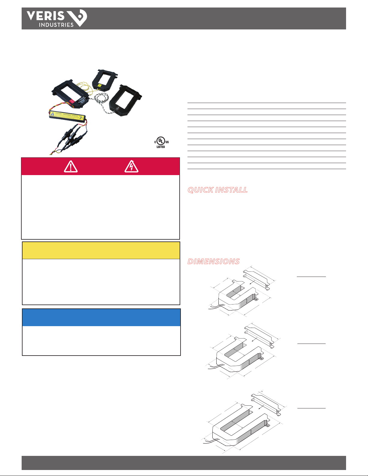
DIMENSIONS
F
B
C
D
A
E
SMALL
100/300 Amp
A = 3.8" (96 mm)
B = 1.2" (30 mm)
C = 1.3" (31 mm)
D = 1.2" (30 mm)
E = 4.0" (100 mm)
F = 4.8" (121 mm)
NOTICE
• This product is not intended for life or safety applications.
• Do not install this product in hazardous or classified locations.
• The installer is responsible for conformance to all applicable codes.
• Mount this product inside a suitable fire and electrical enclosure.
FCC PART 15 INFORMATION
NOTE: This equipment has been tested by the manufacturer and found
to comply with the limits for a class A digital device, pursuant to part
15 of the FCC Rules. These limits are designed to provide reasonable
protection against harmful interference when the equipment is
operated in a commercial environment. This equipment generates,
uses, and can radiate radio frequency energy and, if not installed and
used in accordance with the instruction manual, may cause harmful
interference to radio communications. Operation of this equipment in
a residential area is likely to cause harmful interference in which case
Modifications to this product without the express authorization of
Veris Industries nullify this statement.
For use in a Pollu tion Degree 2 or bet ter environment only. A Pollut ion Degree 2 environme nt must
control conductive pollution and the possibility of condensation or high humidity. Consider the
enclosure, t he correct use of ven tilation, thermal pro perties of the equ ipment, and the relatio nship
with the env ironment. Installat ion category: CAT II or C AT III
Z201640-0H PAGE 1 ©2010 Veris Industries USA 800.354.8556 or +1.503.598.4564 / support@veris.com 11101
B
C
A
B
C
A
Alta Labs, Enercep t, Enspector, Hawkeye, Trustat, Veris, and the Veris ‘ V’ logo are trademark s or registered tradema rks of Veris Industries, L.L .C. in the USA and/or othe r countries.
F
MEDIUM
400/800 Amp
A = 4.9" (125 mm)
D
E
F
B = 2.9" (73 mm)
C = 2.5" (62 mm)
D = 1.2" (30 mm)
E = 5.2" (132 mm)
F = 5.9" (151 mm)
LARGE
800/1600/2400 Amp
A = 4.9" (125 mm)
B = 5.5" (139 mm)
D
E
C = 2.5" (62 mm)
D = 1.2" (30 mm)
E = 7.9" (201 mm)
F = 6.0" (151 mm)
Page 2
TM
H8025/8026
INSTALLATION GUIDE
OPERATION
The H8025 and H8026 three-phase power transducers monitor energy parameters
from aggregate kW (real power) and kWh (consumption) to power factor per phase.
Integration of electronics lowers hardware and installation costs. The sensors
automatically detect phase reversal, so CT load orientation is not a concern. The
CTs and meters are calibrated as a set, so it is necessary to color-match the CTs and
voltage leads when installing.
With two platforms to choose from (H8025 Energy Only or H8026 Enhanced Data
Stream), the applications for these devices are diverse, including aggregate billing,
tenant submetering, energy management, performance contracting, demand
limiting and cooling plant optimization. The 1% total system accurac y conforms to
ANSIC12.1 metering standards.
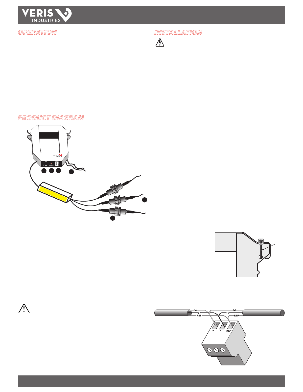
PRODUCT DIAGRAM
®
Enercept
5
4
3
6
INSTALLATION
Disconnect and lock out power before installation.
The Enercept meter, including the current transformers (CTs), voltage connection
fuses, and fusepac, is permitted within electrical distribution equipment including
but not limited to panelboards, switchboards, motor control centers, and
transformers. Carefully review the equipment in which the Enercept meter will be
installed. The following installation conditions should be considered during the
installation process:
• Review the equipment enclosure for ventilation openings. Wires will cross
many of these openings in a normal installation, however, do not install
the Enercept where it will substantially block ventilation openings in the
enclosure.
• The Enercept meter and the wiring installed within a wiring space
or gutter should not exceed 75 percent cross sectional ll at the
Enercept meter parts as addressed in the NEC. Improper installation of
Enercept meter in the wire gut ter of equipment may aect the thermal
performance of the equipment.
• The arrangement of CTs within the equipment must also be considered to
ensure the bending radius of conductors is not adversely aected.
• Review the arrangement and location of the CTs within the equipment.
The CT must not create undue strain on the conductor. A CT may require
appropriate support in order to address such a condition.
Fuse Pack
2
1. Voltage Leads: input range is 208 to 480V.
2. Fuses: maximum current draw 60mA. Fuses provided by the factory are rated
1/2A, 600VAC, 200 KAIC. Replace only with fuses of the same type and rating.
3. Pulse Output connector
4. Status LED: blink codes: slow green for normal operation; slow red for incorrect
wiring or low power factor (less than 0.5); fast red for max. current exceedance.
5. Pulse Rate Switches: used to set the pulse output rate.
6. External CTs: permanently attached; do not disconnect or use with other power
meters.
Color match CTs and voltage leads! Example: clamp the
red labeled CT around the power conductor connected to
the red voltage wire.
1. Choose a unique address and set the switches for that address as shown in the
Address Selection Switches section. Only addresses 1 to 63 can be used.
1
2. Connect the voltage leads to the phase conductors, at a location that is not
normally turned o. Connect voltage leads on the Line side of the conductor to
ensure constant power to the meter. For a 3-phase system, connect the red lead
to phase A, black to phase B, and yellow to phase C. See the Wiring section on the
following page.
3. Snap the CT onto the conductor.
Connect CTs to the correspondingly
colored voltage lead. If the
application can exceed 20 times the
rated CT current, use wire ties to
secure the I-bar to the CT housing.
This CT automatically detects phase
reversal, so CT load orientation is
not important.
4. Remove the terminal block and attach the N2 BUS. Observe (+), (-), and Ref
polarity. Insulate any exposed wiring. When installing multiple meters, attach all
N2 Bus connectors to the network trunk cable, and then connect individual meters
Wire tie
Z201640-0H PAGE 2 ©2010 Veris Industries USA 800.354.8556 or +1.503.598.4564 / support@veris.com 11101
Alta Labs, Enercep t, Enspector, Hawkeye, Trustat, Veris, and the Veris ‘ V’ logo are trademark s or registered tradema rks of Veris Industries, L.L .C. in the USA and/or othe r countries.
Page 3
TM
N2 BUS
ØA
ØB
ØC
120
Neutral
120
N2 bus
Black CT
Red CT
ØA
ØB
Neutral
277
N2 bus
Black CT
Red CT
Yellow C
T
ØA
H8025/8026
INSTALLATION GUIDE
5. Set up Metasys (see Metasys Setup section).
6. Check power reading (these calculations are approximations only).
Expected power:
kW = Volts x Amps x 1.732 x PF / 1000
kW = Horsepower x 0.746
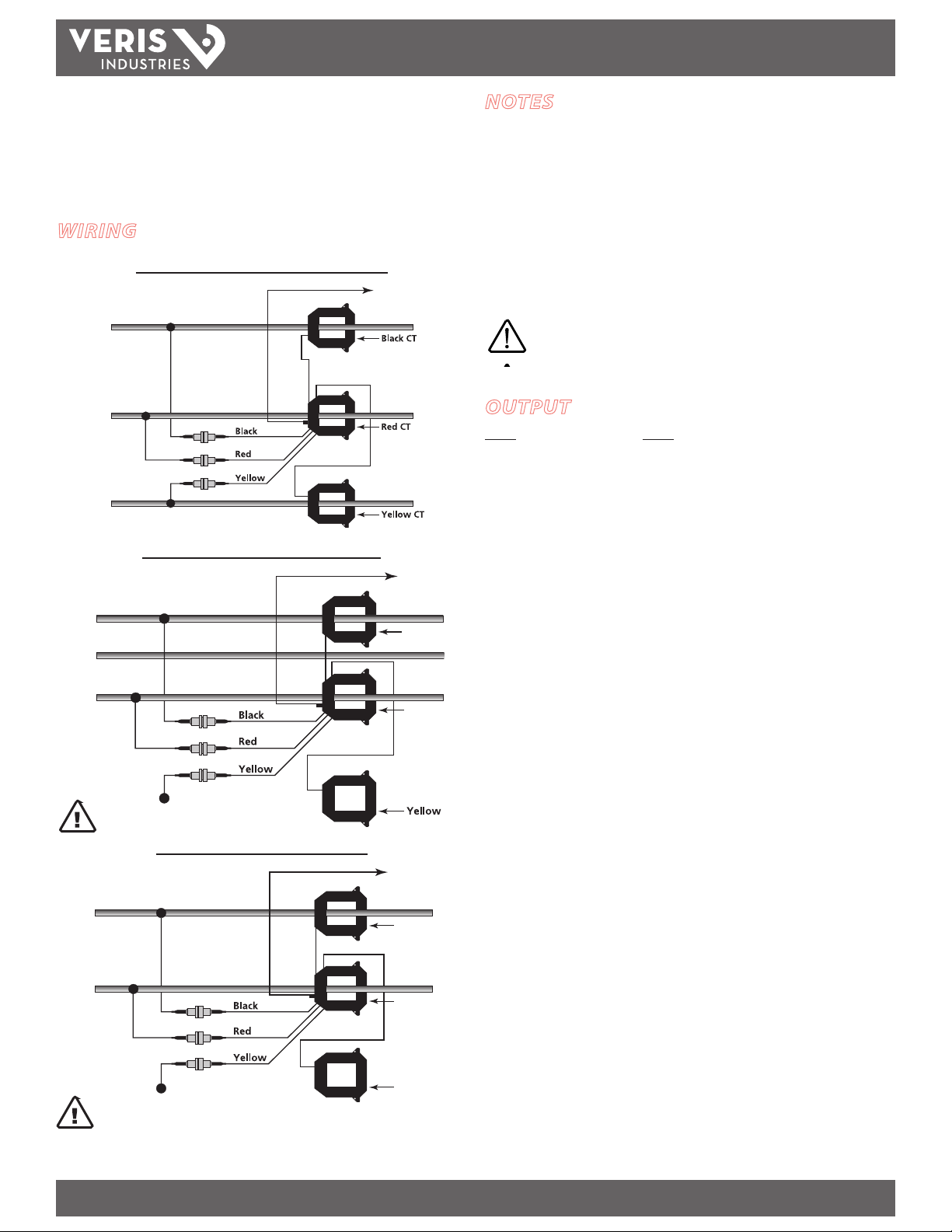
WIRING
Typical 208/480 VAC 3Ø, 3, 4 Wire Installation
Typical 240/120 VAC 1Ø, 3 Wire Installation
(Cap yellow voltage lead)
Typical 277 VAC 1Ø, 2 Wire Installation
NOTES
1. DO NOT GROUND THE N2 BUS REFERENCE INSIDE THE ELECTRICAL PANEL. All N2
lines, including the shield, should be insulated to prevent accidental contact with
high voltage conductors.
2. The N2 BUS cable should be mechanically secured where it enters the electrical
panel.
3. All N2 BUS devices should be connected together in a daisy-chain fashion.
4. The N2 BUS cable should be shielded twisted pair wire BELDEN 1120A or similar.
WARNING: After wiring the N2 BUS cable, remove all
scraps of wire or foil shield from the electrical panel. This
could be DANGEROUS if wire scraps come into contact with
high voltage wires!
OUTPUT
H8025
AC-1: kWh, consumption
BO-1: Reset kWh
AI-1: kW, real power
H8026
AC-1: kWh, consumption
BO-1: Reset kWh
BO-2: Reset min./max./avg.
AI-1: kWh, consumption
AI-2: kW, real power
AI-3: VAR, reactive power
AI-4: VA, apparent power
AI-5: Power factor
AI-6: Average real power
AI-7: Minimum real power
AI-8: Maximum real power
AI-9: Voltage, line-to-line
AI-10: Voltage, line-to-neutral
AI-11: Amps, average current
AI-12: kW, real power ØA
AI-13: kW, real power ØB
AI-14: kW, real power ØC
AI-15: Power factor ØA
AI-16: Power factor ØB
AI-17: Power factor ØC
AI-18: Voltage, ØA to ØB
AI-19: Voltage, ØB to ØC
AI-20: Voltage, ØAto ØC
AI-21: Voltage, ØA to Neutral
AI-22: Voltage, ØB to Neutral
AI-23: Voltage, ØC to Neutral
AI-24: Amps, Current ØA
AI-25: Amps, Current ØB
AI-26: Amps, Current ØC
Note: The meter cannot communicate on the N2 bus without po wer. Therefore, it is best to connect
the voltage leads ahead of switching devi ces.
Z201640-0H PAGE 3 ©2010 Veris Industries USA 800.354.8556 or +1.503.598.4564 / support@veris.com 11101
(Cap yellow voltage lead)
Alta Labs, Enercep t, Enspector, Hawkeye, Trustat, Veris, and the Veris ‘ V’ logo are trademark s or registered tradema rks of Veris Industries, L.L .C. in the USA and/or othe r countries.
Page 4

TM
H8025/8026
INSTALLATION GUIDE
ADDRESS SELECTION SWITCHES
Each device on the N2 BUS must have a unique address. These switches must be set to assign a unique address before the device is connected to the N2 BUS. If an address is
selected which conicts with another device on the N2 BUS, both devices will be unable to communicate.
When setting the N2 BUS address, choose an address number which is not in use. Only N2 addresses in the range of 1 to 63 may be used. Set the switches for the selected
address by following the diagram below. This address will be required when adding the meter to Metasys®.
Z201640-0H PAGE 4 ©2010 Veris Industries USA 800.354.8556 or +1.503.598.4564 / support@veris.com 11101
Alta Labs, Enercep t, Enspector, Hawkeye, Trustat, Veris, and the Veris ‘ V’ logo are trademark s or registered tradema rks of Veris Industries, L.L .C. in the USA and/or othe r countries.
Page 5

TM
H8025/8026
INSTALLATION GUIDE
POINT MAP FOR H8025, N2 PROTOCOL
NPT NPA UNITS POINT DESCRIPTION RANGE/VALUE NOTES
BI 1 kWh, kW* Consumption (accumulation) 100A: 0.0025 kWh/count
300A: 0.01 kWh/count
400A: 0.01 kWh/count
800A: 0.02 kWh/count
1600A: 0.04 kWh/count
2400A: 0.08 kWh/count
AI 1 kWh Consumption 100A: 0 to 10737418.24
2400A: 0 to 343597383.7
AI 2 kW Real Power 100A: 0 to 83.1
2400A: 0 to 1995.3
BO 1 Reset kWh 0 = NA
1 = Reset kWh
ADI 1 Preset kWh, LSW -32768 to 32767 Allows the lower 16 bits of the kWh accumulator to be preset
ADI 2 Preset kWh, MSW -32768 to 32767 Allows the upper 16 bits of the kWh accumulator to be preset
* kWh when displayed in “analog consumption units,” kW when displayed in “analog units.”
** Do not dene BO-1 as auto-restorable. If they are dened in a Metasys CS object or in Companion, they should be commanded to Ø after commanding to 1 to avoin
unintentional reset.
Intended for use as an accumulator (ACM) type. It should not be
read as a binary status.
Allows direct view of kWh accumulator as an AI point. For large
values, BI-1 is more precise.
Resets the kWh accumulator to zero. The value will return to
"o." **
Only BO-1, BO-2, ADI-1, and ADI-2 are capable of being commanded or overridden.
Phase A corresponds to the red lead, Phase B to the black lead, and Phase C to the yellow.
Z201640-0H PAGE 5 ©2010 Veris Industries USA 800.354.8556 or +1.503.598.4564 / support@veris.com 11101
Alta Labs, Enercep t, Enspector, Hawkeye, Trustat, Veris, and the Veris ‘ V’ logo are trademark s or registered tradema rks of Veris Industries, L.L .C. in the USA and/or othe r countries.
Page 6

TM
H8025/8026
INSTALLATION GUIDE
POINT MAP FOR H8026 (ENHANCED DATA STREAM), N2 PROTOCOL
NPT NPA UNITS POINT DESCRIPTION RANGE/VALUE NOTES
BI 1 kWh, kW* Consumption (accumulation) 100A: 0.0025 kWh/count
300A: 0.01 kWh/count
400A: 0.01 kWh/count
800A: 0.02 kWh/count
1600A: 0.04 kWh/count
2400A: 0.08 kWh/count
AI 1 kWh Consumption 100A: 0 to 10737418.24
2400A: 0 to 343597383.7
AI 2 kW Real Power 100A: 0 to 83.1
2400A: 0 to 1995.3
AI 3 kVAR Reactive Power 100A: 0 to 83.1
2400A: 0 to 1995.3
AI 4 kVA VA (apparent power) 100A: 0 to 83.1
2400A: 0 to 1995.3
AI 5 Power Factor, total 0 to 1.0 Reads the eective power factor for all phases (not an average of AI-15, AI-16, and AI-17).
AI 6 kW Average Real Power 100A: 0 to 83.1
2400A: 0 to 1995.3
AI 7 kW Mimimum Real Power 100A: 0 to 83.1
2400A: 0 to 1995.3
AI 8 kW Maximum Real Power 100A: 0 to 83.1
2400A: 0 to 1995.3
AI 9 Volts Voltage, Line-to-Line 0 to 480 Reads the average line to line voltages.
AI 10 Volts Voltage, Line-to-Neutral 0 to 277 Reads the average line to neutral voltages.
AI 11 Amps Current 100A: 0 to 100
2400A: 0 to 2400
AI 12 kW Real Power, ØA 100A: 0 to 27.7
2400A: 664.8
AI 13 kW Real Power, ØB 100A: 0 to 27.7
2400A: 664.8
AI 14 kW Real Power, ØB 100A: 0 to 27.7
2400A: 664.8
AI 15 Power Factor, ØA 0 to 1.0
AI 16 Power Factor, ØB 0 to 1.0
AI 17 Power Factor, ØC 0 to 1.0
AI 18 Volts Voltage, ØA to ØB 190 to 480 The meter is powered by A-B voltage; it will not operate at low voltage.
AI 19 Volts Voltage, ØB to ØC 0 to 480
AI 20 Volts Voltage, ØA to ØC 0 to 480
AI 21 Volts Voltage, ØA to Neutral 0 to 277
AI 22 Volts Voltage, ØB to Neutral 0 to 277
AI 23 Volts Voltage, ØC to Neutral 0 to 277
AI 24 Amps Current, ØA 100A: 0 to 100
2400A: 0 to 2400
AI 25 Amps Current, ØB 100A: 0 to 100
2400A: 0 to 2400
AI 26 Amps Current, ØC 100A: 0 to 100
2400A: 0 to 2400
ADI 1 Amps Preset kWh, LSW -32768 to 32767 Allows the lower 16 bits of the kWh accumulator to be preset
ADI 2 Preset kWh, MSW -32768 to 32767 Allows the upper 16 bits of the kWh accumulator to be preset
BO 1 Reset kWh 0 = NA
1 = Reset kWh
BO 2 Reset Min/Max/Avg 0 = NA
1 = Reset min/max/avg
Intended for use as an accumulator (ACM) type. It should not be read as a binary status.
Allows direct view of kWh accumulator as an AI point. For large values, BI-1 is more precise.
Reads the average real power (kW). This is intended for demand window applications, where
this point is read at the end of each window and then reset via BO-2.
Reads the min. real power since it was reset via BO-2. Real power is internally monitored in
200msec intervals.
Reads the max. (peak) real power since it was reset via BO-2. Peak power is internally
monitored in 200msec intervals.
Reads the current.
Resets the kWh accumulator to zero. The value will return to "o." **
Command to "on" to reset the AI-5, AI-6, and AI-7. THe value will return to "o." **
Z201640-0H PAGE 6 ©2010 Veris Industries USA 800.354.8556 or +1.503.598.4564 / support@veris.com 11101
Alta Labs, Enercep t, Enspector, Hawkeye, Trustat, Veris, and the Veris ‘ V’ logo are trademark s or registered tradema rks of Veris Industries, L.L .C. in the USA and/or othe r countries.
Page 7

TM
H8025/8026
INSTALLATION GUIDE
METASYS SETUP
H8025
1. Dene a hardware object: Type ”N2 Device“, Device type: “VND”
2. Add kWh Accumulator (Consumption) Point: Directly map BI point 1 to an
accumulator (ACM) object at Metasys. Refer to the Range/Value column in the
point map (page 5) for the “pulse constant” which corresponds to the CT size
used. The correct pulse constant must be used to obtain accurate data. The “Rate
Constant” should be “Hour”.
3. Add kW (Instantaneous Demand) Point Directly map AI point 2 to an Analog
Object: Do not use alarm or warning limits (see below). Alternatively, the CS
model le H8025.DDL may be used.
4. Add kWh AI Point (optional): Directly map AI point 1 to an analog object. Do not
use alarm warning limits. Alternatively, the CS model le H8025.DDL may be used.
This AI point provides direct kWH accumulation display.
H8026
1. Dene a hardware object: Type ”N2 Device“, Device type: “VND”
2. Add kWh Accumulator (Consumption) Point: Directly map BI point 1 to an
accumulator (ACM) object at Metasys. Refer to the Range/Value column in the
point map (page 6) for the “pulse constant” which corresponds to the CT size
used. The correct pulse constant must be used to obtain accurate data. The “Rate
Constant” should be “Hour”.
3. Compile the CS model le (H8026.DDL) to add the CS models for the H8026 to your
Metasys database: Type “DDL H8026”.
4. Add CS Object using the model “H8026A”: This allows access to the rst 16 AI
points.
5. Add CS Object using the model “H8026B”: This allows access to the remaining AI
points.
SPECIAL METASYS SETUP OPTIONS
Setting Alarm or Warning Limits
The H8025 and H8026 do not support alarm and warning status reporting for AI
points. If alarm and/or warning limits are required, rst dene a CS object. Then map
an AD object to each CS object AI point value attribute. However, alarm and warning
limits may be used with the accumulator point.
Resetting the kWh Accumulator
current ratio would be 3. If a 20:1 potential transformer is used, then voltage points
would need to be multiplied by 20, current points would need to be multiplied by 3,
and power points would need to be multiplied by 60. Power factor points do not use
multipliers.
The kWh accumulator may be multiplied by changing the “pulse constant.” To apply
multipliers to AI points, use a GPL process to do the math and write the multiplied
value to a pseudo-point.
Displaying kWh
Use totalization to display kWh values. When displayed normally, the accumulator
will show kW instead of kWh. The kW value associated with the accumulator should
agree with AI-2, but it will respond slowly as Metasys® counts kWh over a period of
time to compute kW. Alternatively, AI-1 provides a direct view of the accumulated
kWh. For large values, BI-1 will provide better precision than AI-1.
Presetting the kWh Accumulator
In some cases it may be necessary to preset the kWh accumulator to a specic value
by writing to ADI-1 and ADI-2. To computing the values to write to these points:
1. Divide the desired kWh value by the kWh/count constant that corresponds to
the CT size of the meter (see the point map), and round o to the nearest whole
number. This is the “raw count.”
2. Divide the raw count by 65536 and round down to the nearest whole number.
3. If the value was greater than 32767, subtract 65536. This is the value to write to
ADI-2 .
4. Take the raw count, divide by 65536, subtract out the integer por tion, leaving only
the part to the right of the decimal point, and then multiply by 65536.
5. If the value was greater than 32767, subtract 65536. This is the value to write to
AD I-1.
Both points should be written when there is no power (AI-1 reads zero) to prevent the
values from changing unexpectedly as they are written.
Using the Avg/Min/Max Points (H8026)
The Average Real Power (AI-5), Minimum Real Power (AI-6), and Maximum Real
Power (AI-7) points measure their respective data during a period of time. They begin
after BO-2 is commanded to “1.” A typical usage would be to read these points at a
regular interval, such as ever y 15 minutes, and then command BO-2 immediately
after reading them. Map BO-2 directly to a BO object dened with the auto restore
ag set to “N.”
Point BO-1 resets the kWh accumulator when commanded to “1.” This point will
automatically return to “0” immediately after the kWh accumulator is reset. Map
BO-1 directly to a BO object dened with the auto restore ag set to “N.” This will
prevent an accidental kWh reset if themeter goes o-line and returns. Do not dene
BO-1 with a CS Model, as this would automatically set the auto restore ag to “Y.”
Using Multipliers to Scale Data Points
In high voltage installations where the meter is powered by a potential transformer,
the data must be multiplied by the ratio of the transformer used. Most of these
applications use pre-installed 5 Amp output current transformers, with the 5 Amp
line wrapped many times through the H8025/H8026 meter. Two multipliers exist, one
for the voltage, and one for the eective current ratio. For example, a 300:5 amp CT is
pre-installed and the 5 Amp loop is wound 20 times onto the H8026 meter; eective
Z201640-0H PAGE 7 ©2010 Veris Industries USA 800.354.8556 or +1.503.598.4564 / support@veris.com 11101
Alta Labs, Enercep t, Enspector, Hawkeye, Trustat, Veris, and the Veris ‘ V’ logo are trademark s or registered tradema rks of Veris Industries, L.L .C. in the USA and/or othe r countries.
Page 8

TM
H8025/8026
METASYS MODEL FILES
H8025.DDL
**********************************************************
Veris H8025, Energy Meter
**********************************************************
@M OD EL+
CSMODEL “H8025”,”VND”
INSTALLATION GUIDE
H8026.DDL
**********************************************************
* Veris H8026, Energy Meter, Enhanced Data Stream
**********************************************************
* This le contains two CS models to access all of the AI points
* in the H8026. Two models are required because there are more
* than 16 AI points.
AITITLE “Analog Inputs”
BOTITLE “Binary Outputs”
ADTITLE “Analog Data Points”
CSAI “AI1”,N,N,”CONSUMPT”,”kWH”
CSAI “AI2”,N,N,”POWER”,”kW”
* These two points can be used to preset the kwh accumulator.
* Normally the kwh accumulator only needs to be reset to zero,
* which can be accomplished using BO1. Computing the values
* to write to these points is not simple. In most applications,
* the exact value of the accumulator is not important because
* totalization is used to obtain useful kWH data.
* CSAD “ADI1”,Y,N,”PRESET_L”,”kWH”
* CSAD “ADI2”,Y,N,”PRESET_H”,”kWH”
* The following BO point should be mapped directly to a BO object
* dened with the auto retore ag set to ‘N’.
* CSBO “BO1”,N,N,”RES_kWH”,”n/a”,”reset”
These les may be downloaded from:
http://www.veris.com/hawkeye/revb/h8025.ddl
http://www.veris.com/hawkeye/revb/h8026.ddl
@M OD EL+
CSMODEL “H8026A”,”VND”
AITITLE “Analog Inputs”
BOTITLE “Binary Outputs”
ADTITLE “Analog Data Points”
CSAI “AI1”,N,N,”CONSUMPT”,”kWH”
CSAI “AI2”,N,N,”POWER”,”kW”
CSAI “AI3”,N,N,”REATPOWR”,”kVAR”
CSAI “AI4”,N,N,”APP_POWR”,”kVA”
CSAI “AI5”,N,N,”POW_FACT”,”#”
CSAI “AI6”,N,N,”AVE_PWR”,”kW”
CSAI “AI7”,N,N,”MIN_PWR”,”kW”
CSAI “AI8”,N,N,”MAX_PWR”,”kW”
CSAI “AI9”,N,N,”VOLT_L-L”,”Volts”
CSAI “AI10”,N,N,”VOLT_L-N”,”Volts”
CSAI “AI11”,N,N,”CURRENT”,”Amps”
* These two points can be used to preset the kwh accumulator.
* Normally the kwh accumulator only needs to be reset to zero,
* which can be accomplished using BO1. Computing the values
* to write to these points is not simple. In most applications,
* the exact value of the accumulator is not important because
* totalization is used to obtain useful kWH data.
* CSAD “ADI1”,Y,N,”PRESET_L”,”kWH”
* CSAD “ADI2”,Y,N,”PRESET_H”,”kWH”
* The following BO points should be mapped direc tly to BO objects
* dened with the auto retore ag set to ‘N’.
* CSBO “BO1”,N,N,”RES_kWH”,”n/a”,”reset”
* C SBO “B O2”,N, N,”RE S_ AVG”, ”n/a”,” re se t”
CSMODEL “H8026B”,”VND”
AITITLE “Analog Inputs”
CSAI “AI12”,N,N,”POWER-A”,”kW”
CSAI “AI13”,N,N,”POWER-B”,”kW”
CSAI “AI14”,N,N,”POWER-C”,”kW”
CSAI “AI15”,N,N,”PF_PH-A”,”#”
CSAI “AI16”,N,N,”PF_PH-B”,”#”
CSAI “AI17”,N,N,”PF_PH-C”,”#”
CSAI “AI18”,N,N,”VOLT_A-B”,”Volts”
CSAI “AI19”,N,N,”VOLT_B-C”,”Volts”
CSAI “AI20”,N,N,”VOLT_A-C”,”Volts”
CSAI “AI21”,N,N,”VOLT_A-N”,”Volts”
CSAI “AI22”,N,N,”VOLT_B-N”,”Volts”
CSAI “AI23”,N,N,”VOLT_C-N”,”Volts”
CSAI “AI24”,N,N,”CURRENTA”,”Amps”
CSAI “AI25”,N,N,”CURRENTB”,”Amps”
CSAI “AI26”,N,N,”CURRENTC”,”Amps”
Z201640-0H PAGE 8 ©2010 Veris Industries USA 800.354.8556 or +1.503.598.4564 / support@veris.com 11101
Alta Labs, Enercep t, Enspector, Hawkeye, Trustat, Veris, and the Veris ‘ V’ logo are trademark s or registered tradema rks of Veris Industries, L.L .C. in the USA and/or othe r countries.
Page 9

TM
H8025/8026
TROUBLESHOOTING
Problem Solution
Status LED does not blink Check fuses and voltage connections. Status LED should
Power meter interferes with
another device on the N2 BUS
Readings seem highly inaccurate. •CheckthateachCTisinstalledontheconductorwith
blink regardless of CTs, N2 BUS connections, and DIP
switch setting.
Set DIP switches to a dierent N2 address not in use.
the corresponding color voltage input lead attached. In
most cases, incorrect wiring will cause the STATUS LED
to blink RED (slowly). However, a power factor lower
than 0.5 could cause the LED to blink this way, even if
the unit is installed properly.
•ItdoesnotmatterwhichsideoftheCTfacestowards
the load.
•Ifcurrentisbelow7%offullscalemaximumforthe
CT, use a smaller CT or wrap each wire through the CT
multiple times
•Checkcurrentwithanamp-clamp.
Expected power:
kW = Volts x Amps x 1.732 x PF / 1000
kW = Horsepower x 0.746
PF is usually 0.7 to 0.95, depending on the load.
INSTALLATION GUIDE
Meter goes oine when load is
switched o.
Status LED blinks red. •IftheLEDblinksquickly(i.e.,about5blinksintwo
Voltage leads must be connected on the Line side of the
conductor. The power meter cannot communicate on
the N2 BUS without voltage.
seconds), then the CT rating is too low.
•IftheLEDblinksslowly(i.e.,about1blinkintwo
seconds) the CTs are not installed on the correct
conductors, or the power factor is less than 0.5. The
meter can accurately measure these low PFs, but few
loads operate normally at such a low power factor.
Z201640-0H PAGE 9 ©2010 Veris Industries USA 800.354.8556 or +1.503.598.4564 / support@veris.com 11101
Alta Labs, Enercep t, Enspector, Hawkeye, Trustat, Veris, and the Veris ‘ V’ logo are trademark s or registered tradema rks of Veris Industries, L.L .C. in the USA and/or othe r countries.
 Loading...