

Page 1
TM
operated in a residential environment. This equipment generates, uses,
Power MoNITorING
INSTALLATIoN GUIDe
E31
DANGER
HAZARD OF ELECTRIC SHOCK, EXPLOSION, OR ARC FLASH
• Follow safe electrical work practices. See NFPA 70E in the USA, or applicable local codes.
• This equipment must only be installed and serviced by qualified electrical personnel.
• Read, understand and follow the instructions before installing this product.
• Turn off all power supplying equipment before working on or inside the equipment.
• Use a properly rated voltage sensing device to confirm power is off.
DO NOT DEPEND ON THIS PRODUCT FOR VOLTAGE INDICATION
• Only install this product on insulated conductors.
Failure to follow these instructions will result in death or serious injury.
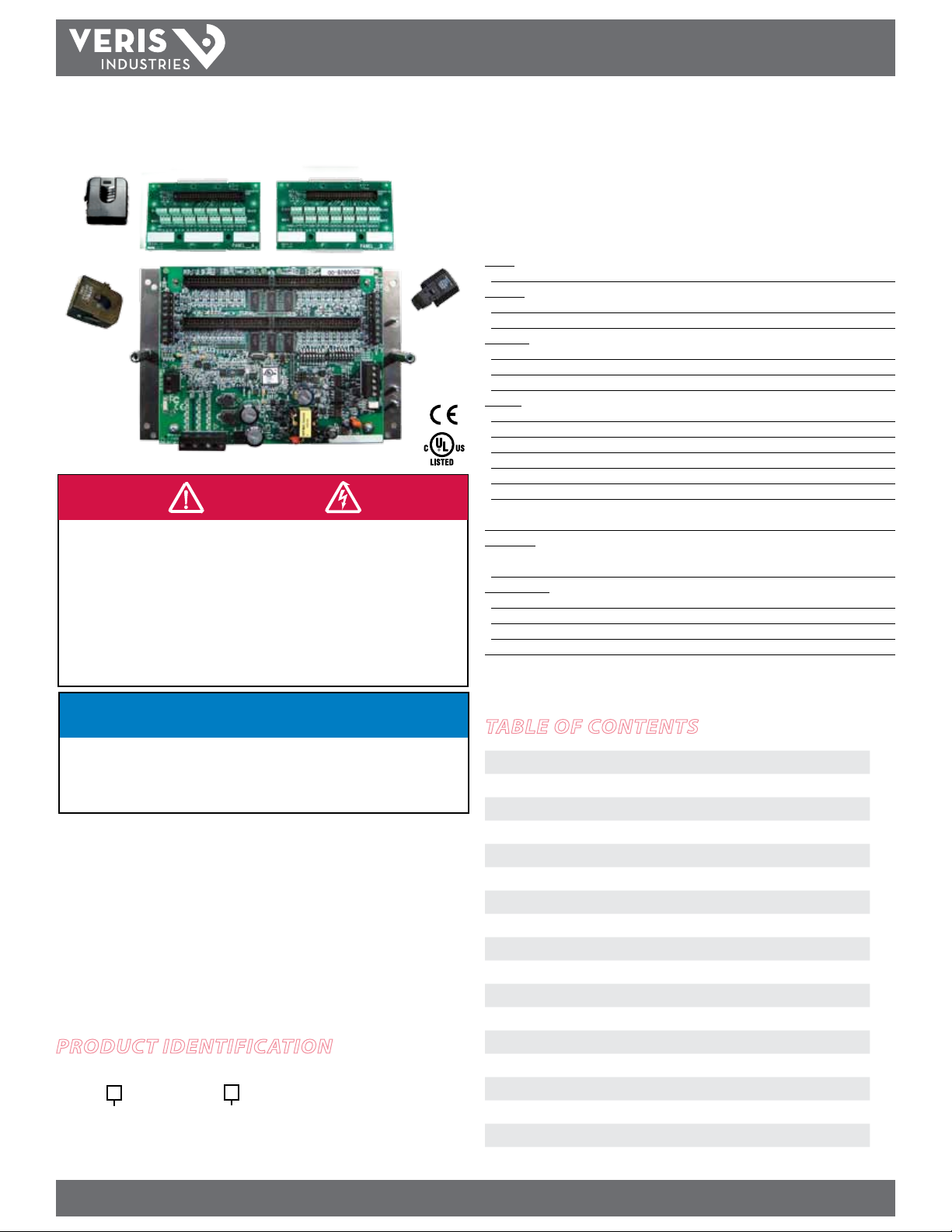
E31
Panelboard Monitoring System
Installer’s Specifications
Inputs:
Input Power 90-277VAC, 50/60 Hz
Accurac y:
Power/Energy IEC 62053-21 Class 1, ANSI C12.1-2008
Volt age ±0.5% of reading 90-277V line-to-neutral
Operation:
Sampling Frequency 2560 Hz
Update Rate 1.8 seconds (both panels)
Overload Capability 22 kAIC
Outputs:
Type Modbus RTU
Connection DIP switch-selectable 2-wire or 4 -wire, RS-485
Address DIP switch-selectable address 1 to 247 (in pairs of 2)*
Baud Rate DIP switch-selectable 9600, 19200, 38400
Parity DIP switch-selectable NONE, ODD, EVEN
Communication Format 8-data-bits, 1-start-bit, 1-stop-bit
Termination 5-position depluggable connector
(TX+ TX- SHIELD TX+/RX+ TX-/RX-)
Mechanical:
Ribbon Cable Suppor t 4 ft. (0.9 m) at ribbon cable ships standard;
up to 20 ft. (6 m) available
Environmental:
Operating Temperature Range 0° to 60°C (32° to 140°F) (<95% RH noncondensing)
Storage Temperature Range -40° to 70°C (-4 0° to 158°F)
Altitude of Operation 3000 m
Agency Approvals UL508, EN61010
* See Conguration section for de tails.
NOTICE
• This product is not intended for life or safety applications.
• Do not install this product in hazardous or classified locations.
• The installer is responsible for conformance to all applicable codes.
• Mount this product inside a suitable fire and electrical enclosure.
FCC PART 15 INFORMATION
NOTE: This equipment has been tested by the manufacturer and found
to comply with the limits for a class B digital device, pursuant to part
15 of the FCC Rules. These limits are designed to provide reasonable
protection against harmful interference when the equipment is
and can radiate radio frequency energy and, if not installed and used
in accordance with the instruction manual, may cause harmful
interference to radio communications. Operation of this equipment in
a residential area may cause harmful interference in which case the
user will be required to correct the interference at his own expense.
Modifications to this product without the express authorization of
Veris Industries nullify this statement.
Product IdentIfIcatIon
Description
E31
A = Advanced b oard
B = Interme diate board
C = Basic boa rd
# of CTs
002 = 2 adapter b oards, no CTs, no cable s
004 = 4 adap ter boards, no CTs, no cab les
42 = 2 adapter boa rds, 42 50A CTs, 4 ft. round r ibbon cables
84 = 4 adapter b oards, 84 50A CTs, 4 ft . round ribbon ca bles
table of contents
Quick Install 2
Operation 2
Dimensions 2
Product Diagram 3
Data Output 3
Blink Codes for Status LED 4
Solid-Core CT Accuracy 4
Installation 4
Wiring 8
Conguration 9
Default DIP Switch Settings 9
Address Setup 10
Commissioning 11
Recommended Accessories 11
Safety 11
Troubleshooting 12
China RoHS Compliance Information IEFUP Table) 12
Z205667-0E PAGE 1 ©2012 Veris Industries USA 800.354.8556 or +1.503.598.4564 / support@veris.com 07121
Alta Labs, Enercep t, Enspector, Hawkeye, Trustat, Veris, and the Veris ‘ V’ logo are trademark s or registered tradema rks of Veris Industries, L.L .C. in the USA and /or other coun tries.
Page 2
e31
TM
INSTALLATIoN GUIDe
quIck Install
Observe precautions for handling static sensitive
devices to avoid damage to the circuitry that
is not covered under the factory warranty.
1. Disconnect and lock out power. Use a properly rated voltage sensing device to
conrm power is o.
2. Mount the main acquisition board in the electrical enclosure.
3. Mount adapter boards to either DIN Rail or SNAPTRACK™.
4. Connect adapter boards to the main board via ribbon cable (sold separately).
5. Connect current transducers to the adapter boards.
6. Snap current sensors onto the conductors to be monitored. Note: ensure that
each split-core CT is closed and firmly seated.
7. Secure wires using strain relief cable ties.
8. Congure communication and addressing parameters using DIP switches.
9. Wire RS-485 communications.
10. Connect CTs to the auxiliary inputs and connect them onto the main conductors
in the enclosure (optional).
11. Wire control power and voltage taps (E31A and E31B only).
12. Download the free E3x conguration tool from www.veris.com to commission the
device for operation.
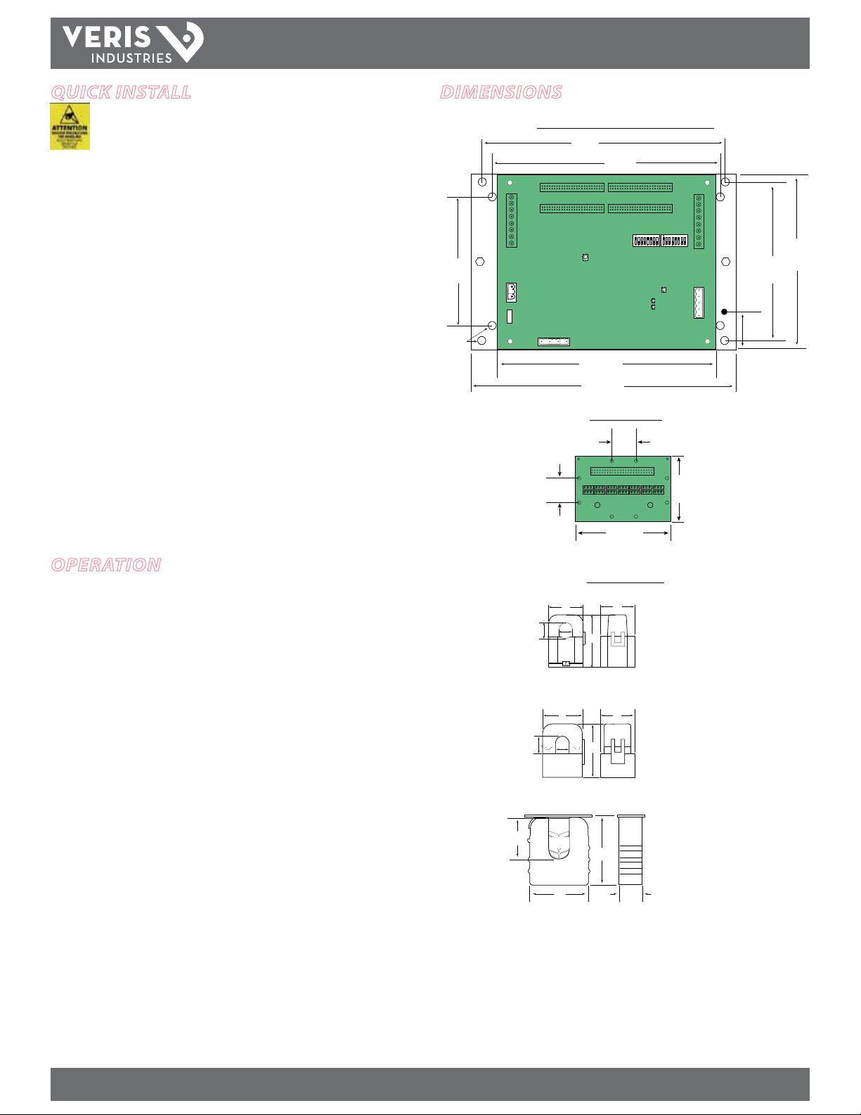
dImensIons
Circuit Board and Mounting Bracket
3.9”
(100 mm)
Ø = 0.2”
(5 mm)
1.00”
(26 mm)
8.3”
(211 mm)
7.3”
(184 mm)
8.9”
(288 mm)
7.9”
(200 mm)
Adapter Board
(26 mm)
(117 mm)
1.00”
4.6”
2.75”
(70 mm)
1.75”
(45 mm)
4.8”
(122 mm)
5.8”
(146 mm)
oPeratIon
The E31 Series Branch Current Monitor is designed to measure the current, voltage,
and energy consumption of up to 92 circuits (84 branch circuits, 2 3-phase mains, 2
neutrals) on a single board. One E31 can monitor up to two panels.
The E31 consists of a data acquisition board and up to 84 split-core current sensors
(50A, 100A, or 200A), with eight auxiliary inputs. Each conductor passes through a
current sensor and terminates at the breaker. Each sensor transmits the current data
to the data acquisition board.
Data is transmitted using an RS-485 Modbus protocol. Each data acquisition board
requires two addresses, one for each set of 42 current sensors and four auxiliary
inputs. Data is updated roughly every two seconds. As a circuit approaches the userdened threshold, the E31 activates the alarm indicators.
The E31A measures both current and power for the mains and branch circuits. The
E31B measures both current and power for the mains, and current only in each circuit.
The E31C measures current only for the mains and branch circuits.
Current Sensors
D
C
B
D
C
B
B
C
A
A
E
A
E
E
D
50 Amp
A = 1.0” (26 mm)
B = 0.5” (11 mm)
C = 0.4” (10 mm)
D = 0.9” (23 mm)
E = 1.6” (40 mm)
100 Amp
A = 1.2” (29 mm)
B = 0.8” (20 mm)
C = 0.7” (16 mm)
D = 1.6” (40 mm)
E = 2.1” (53 mm)
200 Amp
A = 2.6” (66 mm)
B = 1.1” (28 mm)
C = 0.8” (19 mm)
D = 2.9” (74 mm)
E = 3.5” (90 mm)
Z205667-0E PAGE 2 ©2012 Veris Industries USA 800.354.8556 or +1.503.598.4564 / support@veris.com 07121
Alta Labs, Enercep t, Enspector, Hawkeye, Trustat, Veris, and the Veris ‘ V’ logo are trademark s or registered tradema rks of Veris Industries, L.L .C. in the USA and /or other coun tries.
Page 3
e31
TM
INSTALLATIoN GUIDe
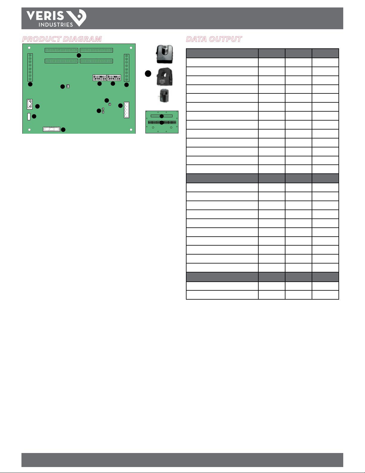
Product dIagram
A A
1
B B
12
8
2
3
4
5
6
1. 50-Pin Ribbon Cable Connectors: Ribbon cables attach here for easy
connection of adapter boards to the data acquisition board. The two connectors
on the left are for panelboard 1; the two on the right are for panelboard 2.
Note: Connect Adapter Boards A and B to the correct ribbon cable connectors
for each panel. The top connec tor is for Adapter Board A, and the bottom
connector is for Adapter Board B.
Note: Ribbon Cable is not included with all E31 models. For ribbon cable
options, see Recommended Accessories on page 11.
2. Auxiliary Inputs: These 0.333VAC inputs are used for monitoring the main
breaker or other high amperage source. Inputs on the lef t are for panelboard 1;
inputs on the right are for panelboard 2.
3. Control (Mains) Power Connection: Easy 2-wire 90-277 VAC 50/60 Hz
connection.
4. Control Power Fuse: 600VAC, 500mA time lag, factory-replaceable.
5. Alive LED: Red/green/amber LEDs. Blink codes are on page 3.
6. Voltage Taps: 1, 2, or 3 phase plus neutral connections. For voltage sensing and
power calculations (no voltage taps on the E31C). Voltage taps are shared by both
panels.
7. Communications Address DIP Switch: Each Modbus device must have a unique
address. Switches are binar y weighted. Left-most switch has a value of 1; rightmost switch has a value of 128. Note: switches set the address for panel 1; panel 2
is automatically set to (Panel 1 address + 1). See Conguration section for details.
7
11
10
2
9
13
14
data outPut
Monitoring at Mains E31A E31B E31C
Current per phase
Max. current per phase
Current demand per phase
Max. current demand per phase
Energy (kWh), total
Real Power (kW) per phase
Apparent Power (kVA)
Power factor, total *
Power factor, per phase
Voltage, L-L and average of 3 phases
Voltage, L-N and average of 3 phases
Voltage, L-N and per phase
Frequency (phase A)
Monitoring at Branch Circuit
Current
Max. current
Current demand
Max. current demand
Real power (kW)
Real power (kW) demand
Real power (kW) demand max.
Energy (kWh) per circuit
Power factor
Apparent Power (kVA)
Modbus Alarms
Voltage over/under
Current over/under
* Based on a 3-phase breaker rotation.
8. Communications Settings DIP Switch: Congures baud rate, parity, 2- or
4-wire communications.
9. RS-485 Connection: Used for Modbus serial communications. The Universal plug
accomodates 2 or 4 wire connections.
10. RS-485 LEDs: The RX LED (closest to DIP switches) indicates the RS-485 is
receiving information; the TX LED indicates transmission of information.
11. Power LED: Indicates power to main board
12. Branch Current Sensors: Each split-core current sensor is capable of monitoring
conductors rated up to a maximum of 50, 100, or 200 amps. Up to 84 sensors can
be purchased with the E31 (see Recommended Accessories on page 10). One of
each style is pic tured here.
13. Ribbon Cable Connection
14. CT Terminal Connections
Z205667-0E PAGE 3 ©2012 Veris Industries USA 800.354.8556 or +1.503.598.4564 / support@veris.com 07121
Alta Labs, Enercep t, Enspector, Hawkeye, Trustat, Veris, and the Veris ‘ V’ logo are trademark s or registered tradema rks of Veris Industries, L.L .C. in the USA and /or other coun tries.
Page 4
e31
TM
INSTALLATIoN GUIDe
blInk codes for status led
Color and Pattern Status Description
Green, once per second Normal operation
Amber, once per second Volts or Amps clipping
Amber, twice per second Invalid rmware image
Red, solid or blink Diagnostic event detected
sPlIt-core ct accuracy
50A Split-Core CT 100A Split-Core CT 200A Split-Core CT
Voltage Rating 300VAC 600VAC 600VAC
Accuracy ±1% ±0.5% ±1%
Temperature 0° to 60°C 0° to 60°C 0° to 60°C
Agency UL508 recognized,
EN61010
UL508 recognized,
EN61010
UL508 recognized,
EN61010
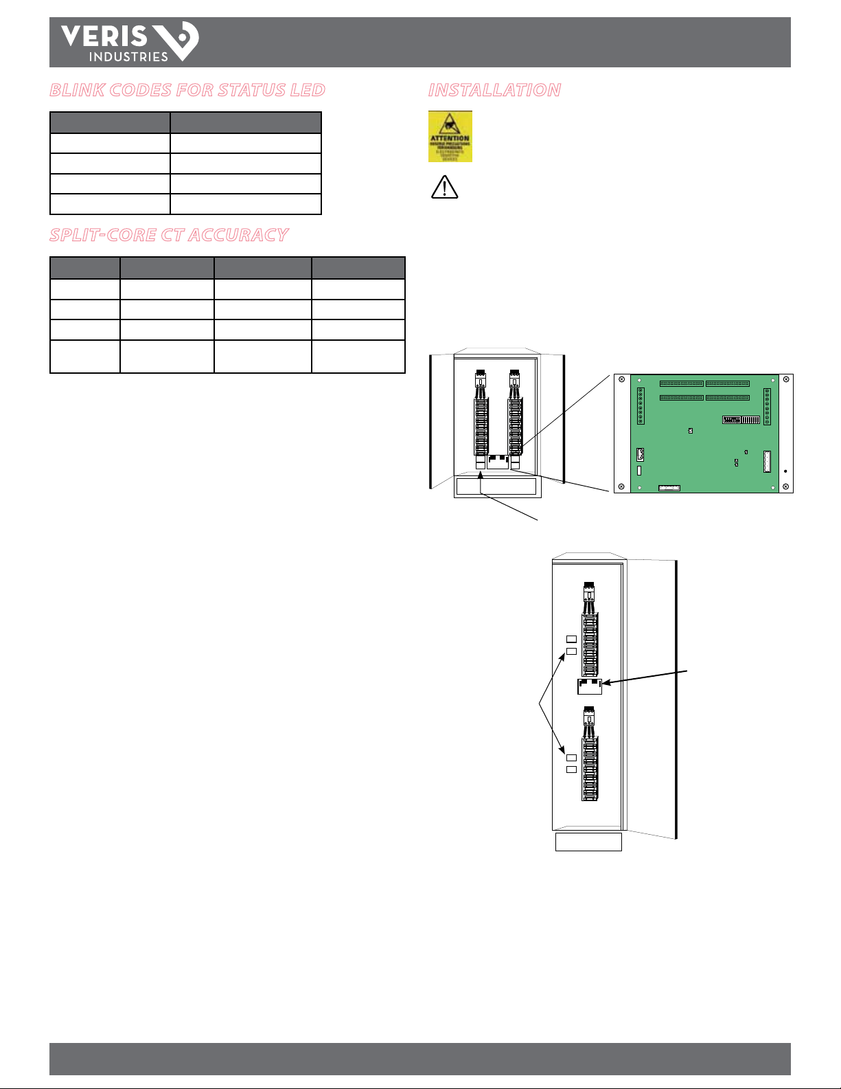
InstallatIon
Observe precautions for handling static sensitive
devices to avoid damage to the circuitry that
is not covered under the factory warranty.
Disconnect power to the electrical panel and lock it out.
1. Install the acquisition board mounting bracket in the panel using screws and bolts
provided Panels can be oriented side-by-side (Figure 1A) or vertically (Figure
1B). A grounding connection is located on the mounting bracket, near the lower
right corner. Use this stud to ground the bracket when mounting on a nonconductivesurface.
Fi gure 1A
Panel 1 Panel 2
Fig ure 1B
Adapter boards
Adapter boards
Panel 1
Main Circuit Board
Panel 2
Z205667-0E PAGE 4 ©2012 Veris Industries USA 800.354.8556 or +1.503.598.4564 / support@veris.com 07121
Alta Labs, Enercep t, Enspector, Hawkeye, Trustat, Veris, and the Veris ‘ V’ logo are trademark s or registered tradema rks of Veris Industries, L.L .C. in the USA and /or other coun tries.
Page 5

e31
TM
2. Mount the adapter boards to either DIN rail or SNAPTRACK.
A. DIN Rail: Use the supplied screws to secure the plastic DIN clip to the
adapter board. Ax the clip to the DIN rail (Figure 2).
B. SNAPTRACK: Secure the SNAPTRACK to the mounting surface. Click the
adapter board into place (Figure 3).
Figure 2 Figure 3
DIN Option 1: Vertical Mount
DIN Option 1: Horizontal Mount
INSTALLATIoN GUIDe
3. Connect adapter boards to the main board using ribbon cable (Figure 4). Ribbon
cables are keyed to ensure proper installation. Orient cables so that the red
stripe is on the left.
Note: Flat and round ribbon cable are available from Veris. See
Recommended Accessories (page 10)
4. Connect current sensors to the terminals on the adapter boards (Figure 4).
Figure 4
Red Stripe
Red Stripe
Red Stripe
Align ribbo n cable key with
connector keyhole.
Orient ribb on cable so that
the red stripe is o n the left
side of the connector.
A A
Pane l 2Pane l 1
B B
Note: Current sensor
orientation does NOT
aect meter accuracy.
Z205667-0E PAGE 5 ©2012 Veris Industries USA 800.354.8556 or +1.503.598.4564 / support@veris.com 07121
Alta Labs, Enercep t, Enspector, Hawkeye, Trustat, Veris, and the Veris ‘ V’ logo are trademark s or registered tradema rks of Veris Industries, L.L .C. in the USA and /or other coun tries.
Page 6

e31
TM
INSTALLATIoN GUIDe
5. Install the current sensors onto the conductors to be monitored (Figure 5).
Sensors can be mounted facing either direction; orientation does not aec t meter
accuracy. Note: Clean split-core contacts before closing. The hinge can detach,
allowing the base and the top to separate for easier cleaning and installation.
Figure 5
The 50 A CT accepts a maximum #2 AWG
(0.384” O.D.) wire with THHN insulation.
The 100A CT accepts a maximum 3/0 AWG
(0.584” O.D.) wire with THHN insulation.
The 200A CT accepts a maximum of 350 MCM
wire with THHN insulation.
Use this gauge wire or smaller for each ci rcuit.
Close CTs until the clasp cl icks
into place to ensur e that contact
surfaces are fi rmly seated.
✓
7. The adapter boards are silk screened with two rows of numbers. For applications
that require odd/even branch circuit numbering, use the row designated ODD or
EVEN. For applications that require sequential numbering, use the number row
marked SEQ (Figure 7).
Figure 7
BLACK
WHITE
41
39
37
35
33
31
29
27
25
23
21
19
17
15
13
11
9
7
ODD
SEQ
531
456
10
11
12
13
14
15
16
17
18
19
20
21
789
123
Adapter Board A numbering:
ODD 1 3 5 7 9 11 13 15 17 19 21 23 25 27 29 31 33 35 37 39 41
SEQ 21 20 19 18 17 16 15 14 13 12 11 10 9 8 7 6 5 4 3 2 1
BLACK
WHITE
42
40
38
36
34
32
30
28
26
24
22
20
18
16
14
12
10
8
EVEN
SEQ
642
42
41
40
39
38
37
36
35
34
33
32
31
30
29
28
27
26
24
24
23
22
Adapter Board B numbering:
6. Plastic cable ties are included with the product for strain relief. Insert the strain
relief device into one of the available holes on the adapter board (Figure 6A).
Gather all current sensor wires connected to that adapter board and secure the
cable tie around them (Figure 6B).
Figure 6
(A) (B)
EVEN 2 4 6 8 10 12 14 16 18 20 22 24 26 28 30 32 34 36 38 40 42
SEQ 22 23 24 25 26 27 28 29 30 31 32 33 34 35 36 37 38 39 40 41 42
Figure 8
A
Pane l 2Pane l 1
B
Panel 1
Mains
Voltage taps are
shared by both panels
Panel 1 uses base Modbus address as set by DI P switches.
Panel 2 uses base + 1 Modbus address as set by DI P switches.
A
B
Panel 2
Mains
Z205667-0E PAGE 6 ©2012 Veris Industries USA 800.354.8556 or +1.503.598.4564 / support@veris.com 07121
Alta Labs, Enercep t, Enspector, Hawkeye, Trustat, Veris, and the Veris ‘ V’ logo are trademark s or registered tradema rks of Veris Industries, L.L .C. in the USA and /or other coun tries.
Page 7

e31
I1
I2
I3
IN
I1
I2
I3
IN
±
±
±
±
±
±
±
±
TM
8. Congure communication and addressing parameters using DIP switches. The E31
requires two addresses, one for each set of 42 current sensors and four auxiliary
inputs. See the Conguration section for more information.
9. Wire RS-485 communications (see diagrams in Wiring section).
10. Connect 0.333VAC current transducers (CTs) to the main conductors by snapping
CTs around lines, observing local codes regarding bending radius (optional;
Figures 9, 10).
INSTALLATIoN GUIDe
Figure 9
Panel 1 Panel 2
Recommended CT:
Veris Industries H6810, H6811, H6812 Series with 0.333VAC output.
Available in 100A max. to 2400A max.
Call a Veris sales rep if higher amperages a re required.
Fig ure 10
CT Input
(0 -0.333 VAC)
Set up Modbus registers 115-118 for CT scaling.
Use base + 1 address for Panel 2 setup.
Note: (+) represents black, (-) represents white
11. Connect 2-wire 90-277VAC power to main power terminals. Observe polarity. For
the E31A and E31B, connect voltage lines to the voltage taps (Figure 11). Equip
voltage lines with fuses.
Pane l 2Pane l 1
CT Input
(0 -0.333 VAC)
Fi gu re 11
V2/N
90 -277 VAC
V1
V1 V2 V3 N
Z205667-0E PAGE 7 ©2012 Veris Industries USA 800.354.8556 or +1.503.598.4564 / support@veris.com 07121
Alta Labs, Enercep t, Enspector, Hawkeye, Trustat, Veris, and the Veris ‘ V’ logo are trademark s or registered tradema rks of Veris Industries, L.L .C. in the USA and /or other coun tries.
L - L L - N
Line to Line (L-L) Voltage: 150 to 480 VAC
Line to Neutral (L-N) voltage: 90 to 277 VAC
Voltage taps are shared by both panels.
Page 8

e31
+
TM
WIrIng
Power must be disconnected and locked out before making any wiring connections.
1. Connect 2-wire or 4-wire Modbus RS-485 daisy chain network (Figures 12 and 13).
INSTALLATIoN GUIDe
Fi gu re 12
SHIELD
RX- TX-
RX+ TX+
TXTX+
Fi gu re 13
2-Wire 4-Wire
Master or Slave
TX+
TX-
RX+
TX+
SHIELD
RX-
TX–
SHLD
SHIELD
2. Mechanically secure the RS-485 cable where it enters the electrical panel.
3. Connect all RS-485 devices in a daisy-chain fashion, and properly terminate the
chain (Figure 14).
4. Shield the RS-485 cable using twisted-pair wire, such as Belden 1120A. The cable
must be voltage-rated for the installation.
Fi gur e 14
TX+
Master
TX+
TX-
TX–
RX+
SHLD
RX-
SHIELD
TX+
Slave
TX+
TX-
TX–
RX+
SHLD
RX-
SHIELD
2-Wire Example
Belden 1120A or
equivalent
120 Ω terminator
on last device of
daisy chain
5. When tightening terminals, ensure that the correct torque is applied: 0.5 to 0.6
N·m (0.37 to 0.44 ft·lb ) for connectors on main board, 0.22 to 0.26 N·m (0.16 to
0.19 ft·lb) for connectors on adapter boards (Figure 15).
WARNING: After wiring the RS-485 cable, remove all
scraps of wire or foil shield from the electrical panel.
Wire scraps coming into contact with high voltage
conductors could be DANGEROUS!
–
Not Used
Fi gur e 15
–
+
Z205667-0E PAGE 8 ©2012 Veris Industries USA 800.354.8556 or +1.503.598.4564 / support@veris.com 07121
Alta Labs, Enercep t, Enspector, Hawkeye, Trustat, Veris, and the Veris ‘ V’ logo are trademark s or registered tradema rks of Veris Industries, L.L .C. in the USA and /or other coun tries.
Page 9

e31
TM
confIguratIon
1. Communications Conguration: Communications parameters for the E31 series
are eld selectable for your convenience. Please see the Product Diagram section
(page 2) for selector location. The following parameters are congurable:
• Baud Rate: 9600, 19200, 38400
• Parity On or O
• Parity: odd or even
• Wiring: 2 or 4
Example: 2-wire 19200 Baud No Parity
Bø
B1
Off/
On
Parity
Odd/
Even
Parity
2/4
Wire
Reserved
INSTALLATIoN GUIDe
3. The E31 uses two logical addresses. Panel 1 uses the base address as set on the DIP
switches, and Panel 2 uses this base address + 1. Address the E31 as any whole
number between and including 1-246. Each unit is equipped with a set of 8 DIP
switches for addressing. See below.
=
1
LSB MSB
1 2 4 8 16 32 64 128
4. To determine an address, simply add the values of any switch that is on.
For example:
LSB
Switch number 4 has an ON Value of 8 and switch number 6 has an ON Value of 32.
(8 + 32 = 40). Therefore, the address for Panel 1 is 40, and the address for Panel 2 is
41.
DIP Switch Values
=
40
MSB
1 2 3 4 5 6 7 8
o o X X X 9600
on o X X X 19200
o on X X X 38400
on on X X X Reserved
o o X X X No Parity
on o X X X Odd Parity
o on X X X No Parity
on on X X X Even Parity
on X X X 4-wire RS-
485
o X X X 2-wire RS-
485
2. Address Conguration: Each Modbus device on a single network must have
a unique address. Set the switch block to assign a unique address before the
device is connected to the Modbus RS-485 network. If an address is selected that
conicts with another device, neither device will be able to communicate.
See the Address Setup section (page 9) for a pictorial listing of the rst 63 switch
positions.
default dIP sWItch settIngs
The E31 includes two DIP switches, as shown below. Switches are shown in their
default positions.
Comms Address Comms Settings
Z205667-0E PAGE 9 ©2012 Veris Industries USA 800.354.8556 or +1.503.598.4564 / support@veris.com 07121
Alta Labs, Enercep t, Enspector, Hawkeye, Trustat, Veris, and the Veris ‘ V’ logo are trademark s or registered tradema rks of Veris Industries, L.L .C. in the USA and /or other coun tries.
Page 10

address setuP
e31
TM
INSTALLATIoN GUIDe
DO NOT
USE ZERO
1 2 3 4 5 6 7 8 9 10
11 12 13 14 15 16 17 18 19 20 21
22 23 24 25 26 27 28 29 30 31 32
33 34 35 36 37 38 39 40 41 42 43
44 45 46 47 48 49 50 51 52 53 54
55 56 57 58 59 60 61 62 63 246
......
Z205667-0E PAGE 10 ©2012 Veris Industries USA 800.354.8556 or +1.503.598.4564 / support@veris.com 07121
Alta Labs, Enercep t, Enspector, Hawkeye, Trustat, Veris, and the Veris ‘ V’ logo are trademark s or registered tradema rks of Veris Industries, L.L .C. in the USA and /or other coun tries.
Page 11

e31
TM
INSTALLATIoN GUIDe
commIssIonIng
1. Reconnect power to the panel.
2. Congure installation mode using Modbus Register 6.
3. Congure CT scaling.
4. Congure alarms.
5. Congure demand.
Download the free E3x conguration tool from www.veris.com to commission the
device for operation.
recommended accessorIes
Part ID Description
CBL008 Flat ribbon cable, 50 x 28 AWG, 1.5 ft. (0.45 m)
CBL016 Flat ribbon cable, 50 x 28 AWG, 4 ft. (1.2 m)
CBL017 Flat ribbon cable, 50 x 28 AWG, 5 ft. (1.5 m)
CBL018 Flat ribbon cable, 50 x 28 AWG, 6 ft. (1.8 m)
CBL019 Flat ribbon cable, 50 x 28 AWG, 8 ft. (2.4 m)
CBL020 Flat ribbon cable, 50 x 28 AWG, 10 ft. (3.0 m)
CBL021 Flat ribbon cable, 50 x 28 AWG, 20 ft. (6.1 m)
CBL022 Round ribbon cable, 50 x 28 AWG, 4 ft. (1.2 m)
CBL023 Round ribbon cable, 50 x 28 AWG, 10 ft. (3 m)
CBL024 Round ribbon cable, 50 x 28 AWG, 20 ft. (6 m)
CBL025 Flat ribbon cable, 50 x 28 AWG, 2 m
CBL026 Flat ribbon cable, 50 x 28 AWG, 4 m
CBL027 Flat ribbon cable, 50 x 28 AWG, 6 m
CBL031 Round ribbon cable, 50 x 28 AWG, 1.5 ft. (0.45 m)
CBL032 Round ribbon cable, 50 x 28 AWG, 2.5 ft. (0.76 m)
E31CT0 Six-pack 50 A CT, 6 ft. (1.8 m) lead
E31CT0R20 Six-pack 50 A CT, 20 ft. (6 m) lead
E31CT1 Six-pack 100 A CT, 6 ft. (1.8 m) lead
E31CT1R20 Six-pack 100 A CT, 20 ft. (6 m) lead
E31CT3 Single 200A CT, 6ft (1.8m) lead
E31CT3R20 Single 200A CT, 20ft (6m) lead
E31CTDB 2 E31 Adapter boards
AE001 E3x MCB Cover
AV01 Veris DIN Rail
safety
If Veris E31 products are used in installations with circuits higher than the product
ratings, the circuits must be kept segregated per UL508A Sec. 17.5.
Note: 277/480VAC Wye connected (center grounded) power systems operate
within the 300VAC line to neutral safety rating of the E3x series, and the
operational voltage limit (single-phase connection) as the line to neutral
voltage is 277VAC in such power systems. Corner-grounded delta 480VAC
systems would not qualif y, as the actual line to earth voltage is 480VAC on
each leg, exceeding the E3x ratings.
Note: E3x internal circuitr y (cables and CTs) are not circuits as dened by
UL508A, as they do not extend beyond the E3x itself without further safety/
re isolation.
UL listed under standard 508 as an “open type device.”
Maximum ambient air temperature for use is 60°C.
Installation categor y: CAT III
The E31 Series must be installed in an appropriate electrical and re enclosure per
local regulations.
For use in a Pollution Degree 2 or better environment only.
A Pollution Degree 2 environment must control conductive pollution and the
possibility of condensation or high humidit y. Consideration must be given to the
enclosure, the correct use of ventilation, thermal properties of the equipment and the
relationship with the environment.
If the equipment is used in a manner not specied by the manufacturer, the
protection provided by the device may be impaired.
IEC/EN 61010-1
This symbol indicates an electrical shock hazard exists.
Documentation must be consulted where this symbol is used on the
product.
Z205667-0E PAG E 11 ©2012 Veris Industries USA 800.354.8556 or +1.503.598.4564 / support@veris.com 07121
Alta Labs, Enercep t, Enspector, Hawkeye, Trustat, Veris, and the Veris ‘ V’ logo are trademark s or registered tradema rks of Veris Industries, L.L .C. in the USA and /or other coun tries.
Page 12

TM
troubleshootIng
Problem Solution
Product is not communicating over Modbus daisy chain
RX LED is solid
The main board has a fast ashing amber light
The main board has a slow ashing amber light
The main board has a ashing green light
The main board is a ashing or solid red light
Split-core product is reading zero for some values
Power factor reading is not as expected
Current reading is not as expected, or reading is on dierent CT
number than expected
Current is reading zero, even when small currents are still
owing through circuit
E3x Cong Tool returns Modbus error on read/write
e31
• Check the unit Modbus address to ensure that each device on the daisy chain has a unique address.
• Check Parity.
• Check the communications wiring.
• Check that the daisy chain is properly terminated.
• Check for reversed polarity on Modbus comms.
• Check for sucient biasing on the Modbus bus. Modbus physical specication calls for 450-650 Ω biasing. This is usually
provided by the master.
• Verify ribbon cable connectors are inserted in the correct orientation.
• If cables are correct, reset main board to re-initialize product.
• One or more channels is clipping. This can be caused by a signal greater than the split-core size or 277 V L-N, or by a signal
with high THD near the gain stage switching points (1.5 A and 10 A).
• Everything is wired properly and the main board has power.
• Light may be red briey while device powers up.
• If light is red for more the 60 sec. device has encountered a diagnostic event. Contact technical support.
• Device was unable to read split-core adapter boards on power up. Verify adapter boards are connected.
• Verify ribbon cable connectors are inserted in the correct orientation.
• Reset main board to re-initialize product.
• Verify voltage taps are connected in appropriate phase rotation.
• Verify phase rotation of breakers (rmware rev. 1.012 or higher allows for custom rotation if needed).
• Verify ribbon cable is fully seated and in the correct orientation.
• The product cuts o at 50 mA, and will set the reporting register to 0 mA for currents near or below this range.
• Verify using the latest release of E3x Cong Tool as older versions may not support all features in current product rmware.
Latest version is available on our website http://www.veris.com/modbus.aspx
INSTALLATIoN GUIDe
chIna rohs comPlIance InformatIon (efuP table)
产品中有毒有害物质或元素的名称及含量Substances
部件名称
铅 (Pb) 汞 (Hg) 镉 (Cd) 六价铬 (Cr(VI)) 多溴联苯(PBB) 多溴二苯醚(PBDE)
电子线路板 X O O O O O
O = 表示该有毒有害物质在该部件所有均质材料中的含量均在 SJ/T11363-2006 标准规定的限量要求以下.
X = 表示该有毒有害物质至少在该部件的某一均质材料中的含量超出SJ/T11363-2006标准规定的限量要求.
Z000057-0A
Z205667-0E PAGE 12 ©2012 Veris Industries USA 800.354.8556 or +1.503.598.4564 / support@veris.com 07121
Alta Labs, Enercep t, Enspector, Hawkeye, Trustat, Veris, and the Veris ‘ V’ logo are trademark s or registered tradema rks of Veris Industries, L.L .C. in the USA and /or other coun tries.
 Loading...