

Page 1
Installation Guide
Accessories
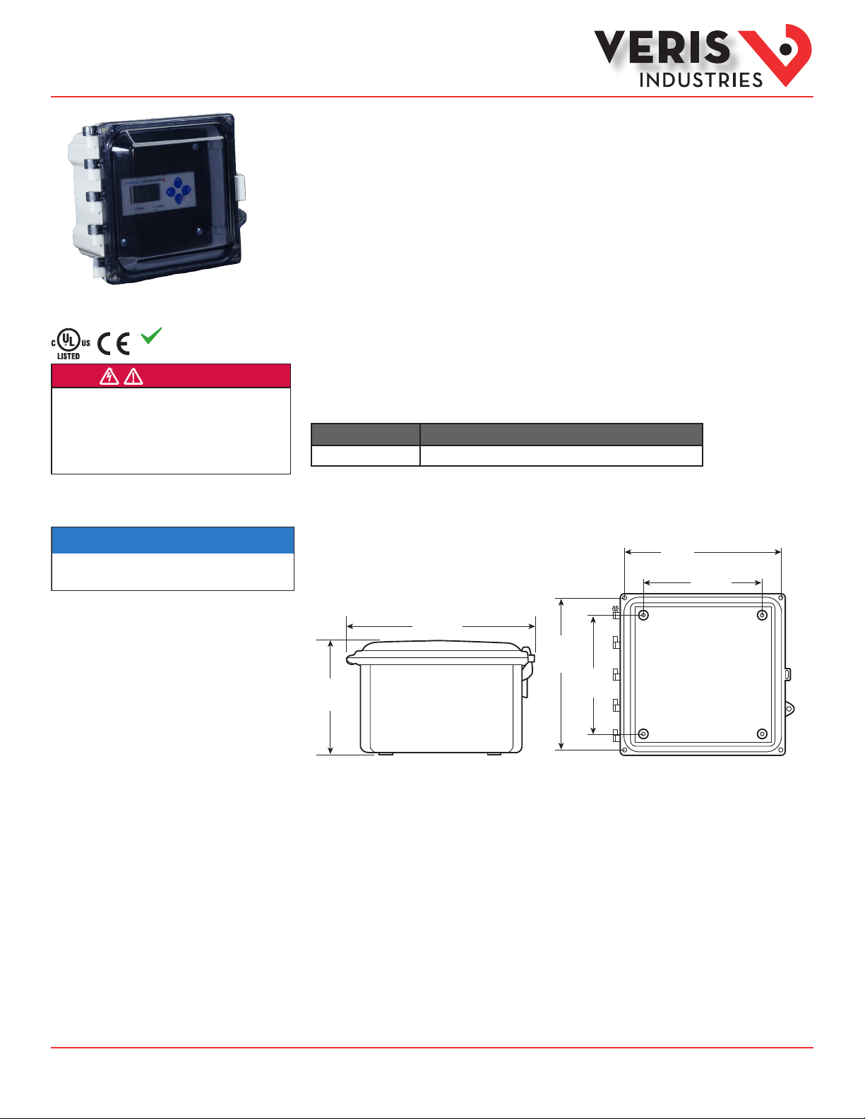
Pictured with the E5x meter
installed. E5x meter an d AE012
enclosure are purch ased separately.
RoHS
Compliant
DANGER
HAZARD OF ELECTRIC SHOCK, EXPLOSION, OR ARC FLASH
• Follow safe electrical work practices. See NFPA 70E in the USA, or applicable local codes.
• This equipment must only be installed and serviced by qualified electrical personnel.
• Read, understand and follow the instructions before installing this product.
• Turn off all power supplying equipment before working on or inside the equipment.
• Use a properly rated voltage sensing device to confirm power is off.
DO NOT DEPEND ON THIS PRODUCT FOR VOLTAGE INDICATION
Failure to follow these instructions will result in death or serious injury.
A qualied person is one who has skills and knowledge related to the construction and
operation of this electrical equipment and the installation, and has received safety
training to recognize and avoid the hazards involved. NEC2011 Article 100
No responsibility is assumed by Veris Industries for any consequences arising out of the
use of this material.
NOTICE
• This product is not intended for life or safety applications.
• Do not install this product in hazardous or classified locations.
• The installer is responsible for conformance to all applicable codes.
TM
AE012
Enclosure for E5x Series Energy Meters
With Swing Panel Kit
Product Overview
The AE012 enclosure oers a mounting option for E5x Series energy meters that helps protect from tampering
and the elements. The enclosure is equipped with DIN rail mounting hardware for easy installation and a NEMA 4X
rating for durability. The swing panel kit and multiple locking options provide additional security from unwanted
tampering.
Product Identification
Part Number Description
AE012 NEMA 4X enclosure for E5x meters with swing panel kit
Dimensions
6.75”
(172 mm)
4.25”
(108 mm)
5.3”
(76 mm)
8.5”
(216 mm)
6.75”
(172 mm)
4.25”
(108 mm)
ZL0120 -0A Page 1 of 5 ©2013 Veris Industries USA 800.354.8556 or +1.503.598.4564 / support@veris.com 08131
Alta Labs, E nercept, Ensp ector, Hawkeye, Trus tat, Aerospo nd, Veris, and th e Veris ‘V’ log o are tradema rks or registe red tradema rks of Veris Ind ustries, L. L.C. in the USA and /or other countri es.
Other companies’ trademarks are hereby acknowledged to belong to their respective owners.
Page 2
Installation Guide
Accessories
AE012
TM
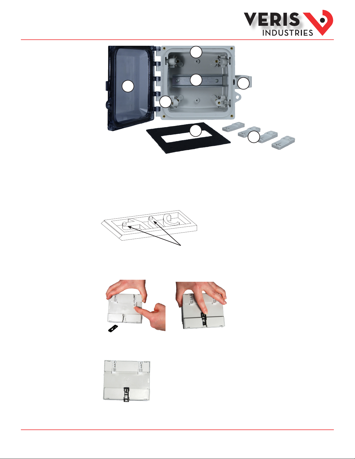
Product
Components
Installation
1
2
3
4
5
1. Enclosure
2. DIN rail
3. Hinged lid
4. Clasp
5. Brackets for swing panel cover
6. Swing panel cover
7. Mounting feet
(hardware not pic tured)
6
7
1. Install DIN rail clips to the back of the E5x
The E5x is shipped with a set of three DIN rail clips included. Insert these clips into the slots on the back of the housing from the
middle, moving outward. Stopping pegs must face the underside of the housing. Push clips into place until there is an audible
click.
DIN Rail clip
(included with E5x meter)
When attaching the clips to the unde rside
of the E5x meter, these stopping pegs must
face inward towards the meter housing. Set
pegs into the available slots o n the meter,
with the beveled side of the clip facing
toward the center of the meter.
When all clips are in place, the white clips must be ush with the top edge of the housing, and the black clip must protrude slightly
past the bottom edge.
ZL0120 -0A Page 2 of 5 ©2013 Veris Industries USA 800.354.8556 or +1.503.598.4564 / support@veris.com 08131
Alta Labs, E nercept, Ensp ector, Hawkeye, Trus tat, Aerospo nd, Veris, and th e Veris ‘V’ log o are tradema rks or registe red tradema rks of Veris Ind ustries, L. L.C. in the USA and /or other countri es.
Other companies’ trademarks are hereby acknowledged to belong to their respective owners.
Page 3

Installation Guide
Accessories
AE012
TM
Installation (cont.)
2. Mount the AE012 enclosure to a wall or panel
Cut holes in the enclosure for wire conduit connections prior to the installation of the meter in the
enclosure. After running the wiring, seal all holes properly to maintain the enclosure rating. If using
metallic conduit, bonding between the conduit connections is not automatic and must be provided as a
part of the installation.
Take care to protect the equipment from drill chips, lings, and other contaminants when making the
wire entry holes and mounting the enclosure to prevent component damage or a future malfunction.
Use the included mounting hardware to attach the mounting feet to the enclosure. Then mount the enclosure to the wall or panel
using either a 4-point or 2-point conguration (hardware for mounting to the wall/panel is provided by the installer). The 4-point
conguration is shown here. For a 2-point conguration, mount the feet as shown, but rotate the bottom feet 180° so they are
ush against the back of the enclosure.
3. Install E5x Onto DIN Rail Inside the AE012
Run E5x wiring through the holes drilled previously. Wire the E5x according to the instructions in the E5x installation guide.
Push the top of the E5x onto the DIN rail.
ZL0120 -0A Page 3 of 5 ©2013 Veris Industries USA 800.354.8556 or +1.503.598.4564 / support@veris.com 08131
Alta Labs, E nercept, Ensp ector, Hawkeye, Trus tat, Aerospo nd, Veris, and th e Veris ‘V’ log o are tradema rks or registe red tradema rks of Veris Ind ustries, L. L.C. in the USA and /or other countri es.
Other companies’ trademarks are hereby acknowledged to belong to their respective owners.
Page 4

Installation Guide
Accessories
AE012
TM
Installation (cont.)
Push the bottom of the meter onto the DIN rail until there is an audible click.
If necessary, remove the E5x from the DIN rail using a at screwdriver to pr y out the bottom (black) clip while lifting out the
bottom of the meter.
Lower the four brackets so that the swing panel cover can be attached using the enclosed hardware.
ZL0120 -0A Page 4 of 5 ©2013 Veris Industries USA 800.354.8556 or +1.503.598.4564 / support@veris.com 08131
Alta Labs, E nercept, Ensp ector, Hawkeye, Trus tat, Aerospo nd, Veris, and th e Veris ‘V’ log o are tradema rks or registe red tradema rks of Veris Ind ustries, L. L.C. in the USA and /or other countri es.
Other companies’ trademarks are hereby acknowledged to belong to their respective owners.
Page 5

Installation Guide
Accessories
AE012
TM
Close the hinged lid and secure the clasp to close.
Screws are provided to secure the hinged lid. Local codes may require this step to prevent opening by unauthorized persons if a
locking mechanism is not used. For added security, the installer may add a locking mechanism.
Optional: Use included
hardware to secure the
hinged lid at all four corn ers.
Optional: Attach locking m echanism here
(not included)
ZL0120 -0A Page 5 of 5 ©2013 Veris Industries USA 800.354.8556 or +1.503.598.4564 / support@veris.com 08131
Alta Labs, E nercept, Ensp ector, Hawkeye, Trus tat, Aerospo nd, Veris, and th e Veris ‘V’ log o are tradema rks or registe red tradema rks of Veris Ind ustries, L. L.C. in the USA and /or other countri es.
Other companies’ trademarks are hereby acknowledged to belong to their respective owners.
 Loading...