

Page 1

Veris Technologies
1
Operating Instructions
Pub. #OM 1CM02-1
2000XA Soil EC Mapping System
Table of Contents
P. 3-7 Installation and set-up
P. 7-11 Maintenance and Lubrication
P. 12-15 Field Operations
P. 17-18 Troubleshooting
P. 19-20 Updating Firmware
P. 21 Formatting Compact Flash
Page 2
Veris Technologies
2
Pub. #OM 1CM02-1
VERIS 2000XA SOIL EC MAPPING SYSTEM
(software v.1.76e)
)
OPERATING INSTRUCTIONS
Warranty
Veris Technologies warrants this product to be free of defects in materials and workmanship for a
period of one (1) year from the date of delivery to the purchaser. Veris Technologies will repair or
replace any product returned to Salina, Kansas, which appears upon inspection to be defective in
materials or workmanship. Veris Technologies will have shall have no obligation under this warranty
for the cost of labor, down-time, transportation charges, or for the repair or replacement of any
product that has been misused, carelessly handled, modified, or altered.
ALL OTHER WARRANTIES OF ANY KIND, WHETHER EXPRESSED OR IMPLIED, INCLUDING
BUT NOT LIMITED TO ANY IMPLIED WARRANTY OF MERCHANTABILITY OR OF FITNESS FOR
A PARTICULAR PURPOSE AND ALL CLAIMS FOR CONSEQUENTIAL DAMAGES, ARE
SPECIFICALLY DISCLAIMED AND EXCLUDED.
Important! Read the following SAFETY PROCEDURES before operating the Veris 2000XA:
1) To prevent possible electrical shock, or damage to the instrument, do not connect to any
power source greater than twelve (12) volts DC.
Page 3
3
2) Never allow anyone to ride on the implement during operation.
3) Lift the implement only with the provided ratchet jack.
4) Properly support the unit before performing any adjustment or maintenance.
5) Due to its small size and narrow design, it is not intended for high-speed travel on public
roads. If you choose to do so, contact your state Department of Transportation for safety
markings and guidelines. Veris Technologies suggests trailer transport.
Installation and Set-up
Instrument
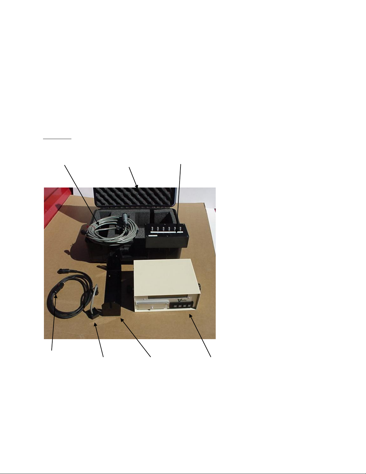
The Veris EC Instrument Kit (PN 15161) includes the following:
Signal cable Protective case Test Box
Veris Technologies
Pub. #OM 1CM02-1
Power Cable Test Load Mounting Bracket EC Instrument
Make sure that you have received all of these components in your EC Package.
Mount instrument in a location that is as free as possible from dust, vibration, and electrical
interference. Display should be visible to operator and shielded from direct sunlight.
Page 4
4
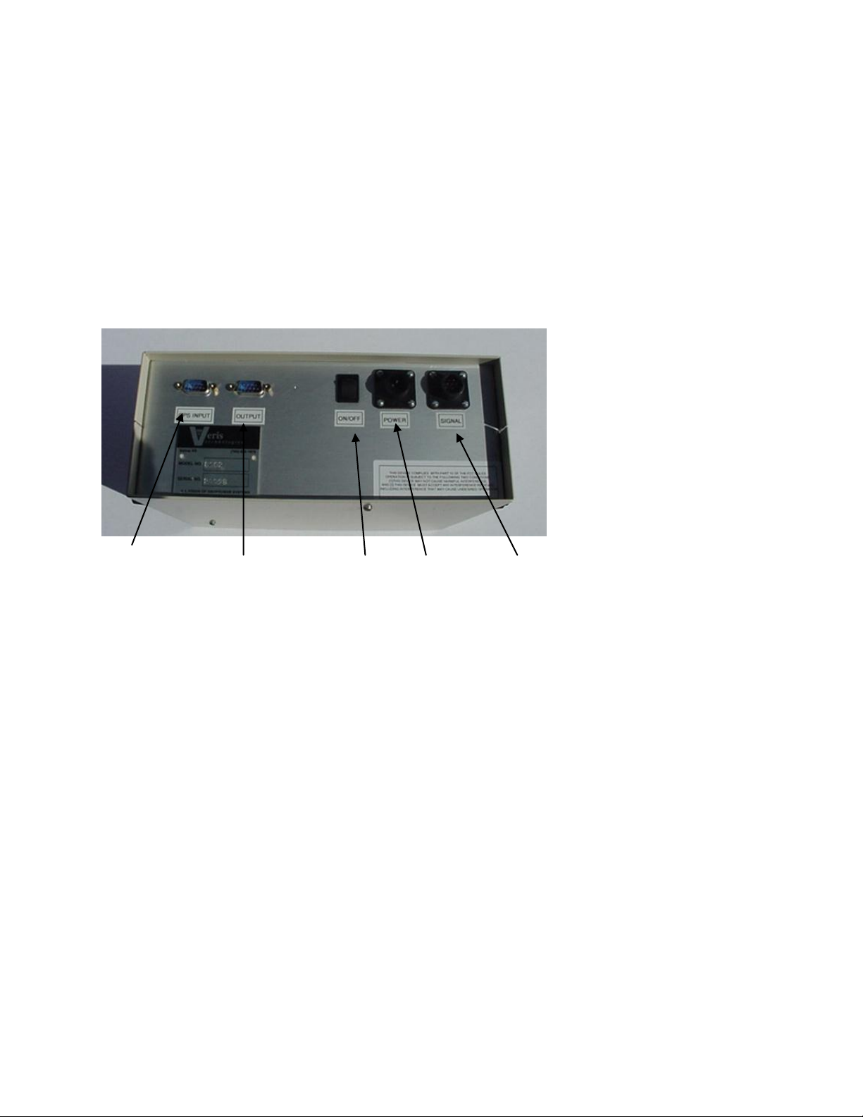
Below is a rear view of the instrument
Veris Technologies
Pub. #OM 1CM02-1
Serial Port for Serial Port for Power Power cable Signal Port
GPS Signal Listening Computer Switch Port For signal cable
or Test Load
Connect GPS cable to GPS INPUT serial port on back of instrument. The Veris instrument is
designed to accept GPS input in NMEA format via an RS232 connector. Note: GPS signals are
frequently affected by electrical interference from magneto electrical systems. If your vehicle uses a
magneto, consider powering the Veris instrument with a 12-volt battery or converting to an alternator
system.
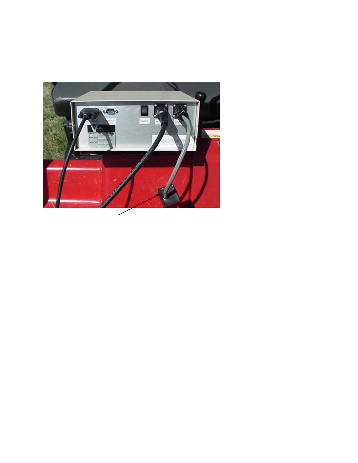
The Veris 2000XA is shipped with an accessory power plug. If an alternative connection is desired,
make sure that the unit is properly connected to a power connection that is not controlled by the
ignition switch. If connecting directly to the battery, we suggest a 3 amp. in-line fuse is installed
between the battery and the instrument. Important – Do not allow moisture to enter the
instrument, and do not pass strong magnets near the unit.
Signal Testing – The Veris 2000XA is shipped with an Instrument Test Load (Part No. 10447) that
will enable you to quickly check the instrument to ensure that it is functioning properly. To perform this
test, do the following:
1) Disconnect the signal cable from the 9-pin (signal) terminal on the instrument.
2) Connect the test load to the signal terminal.
3) Switch on the unit and go into “data acquisition” mode.
4) The display should show: (approx.)
Shallow 14 Not used on VS 2000XA
Deep 21
Page 5
5
Veris Technologies
Pub. #OM 1CM02-1
5) If the readings vary greatly (more than one whole number) contact our service
department.
6) Once the test is complete, remove the test load and reinstall the implement signal cable.
Test Load
Note: It is advisable to conduct this test as a routine check to ensure that you are obtaining
reliable data.
Note: This equipment has been tested and found to comply with the limits for a Class A
digital device, pursuant to Part 15 of the FCC rules. These limits are designed to provide
reasonable protection against harmful interference when the equipment is operated in a
commercial environment. This equipment generates, uses, and can radiate radio frequency
energy and, if not installed and used in accordance with the instruction manual, may cause
harmful interference to radio communications. Operation of this equipment in a residential
area is likely to cause harmful interference in which case the user will be required to correct
the interference at their own expense. Changes and modifications not expressly approved by
Veris Technologies could void the user’s authority to operate the Veris 2000XA.
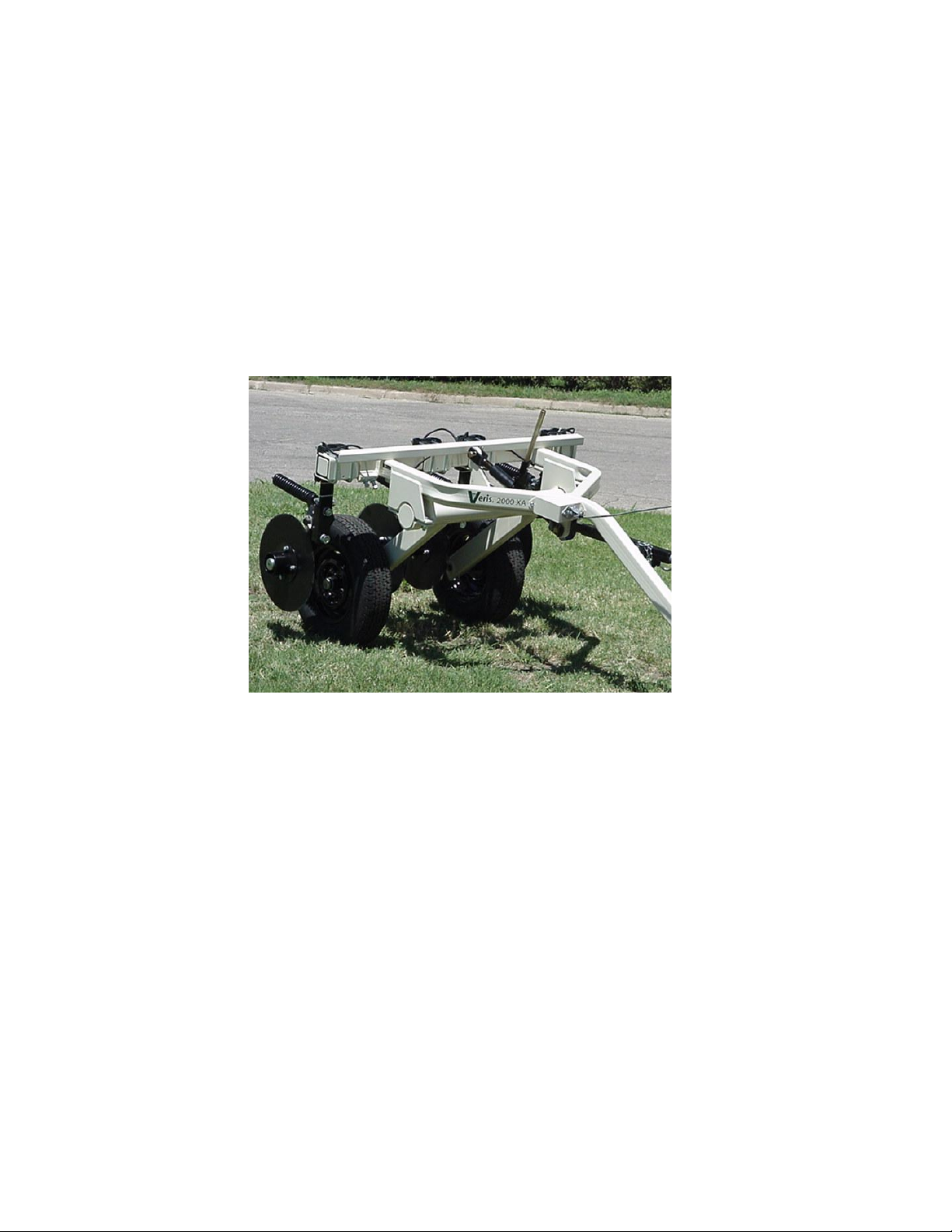
Implement
Prior to operating the implement for the first time, it is important to check the following:
1) All fasteners – some may have loosened during shipment.
2) Coulter electrode isolation – check so see that no metal part of the any coulter electrode
is in contact with the implement frame. This may be by visual inspection or by connecting
one lead of an ohmmeter to the individual coulter electrode, and the other to a grounded
fastener on the frame. If the coulter electrode is properly isolated, no reading will be
obtained. Make sure that all electrode coulter clamp bolts are properly tightened to
prevent lateral movement of the coulter electrode
Page 6
6
Coulter Electrode Isolation
Veris Technologies
Pub. #OM 1CM02-1
Grounded bolt Ohmmeter Coulter
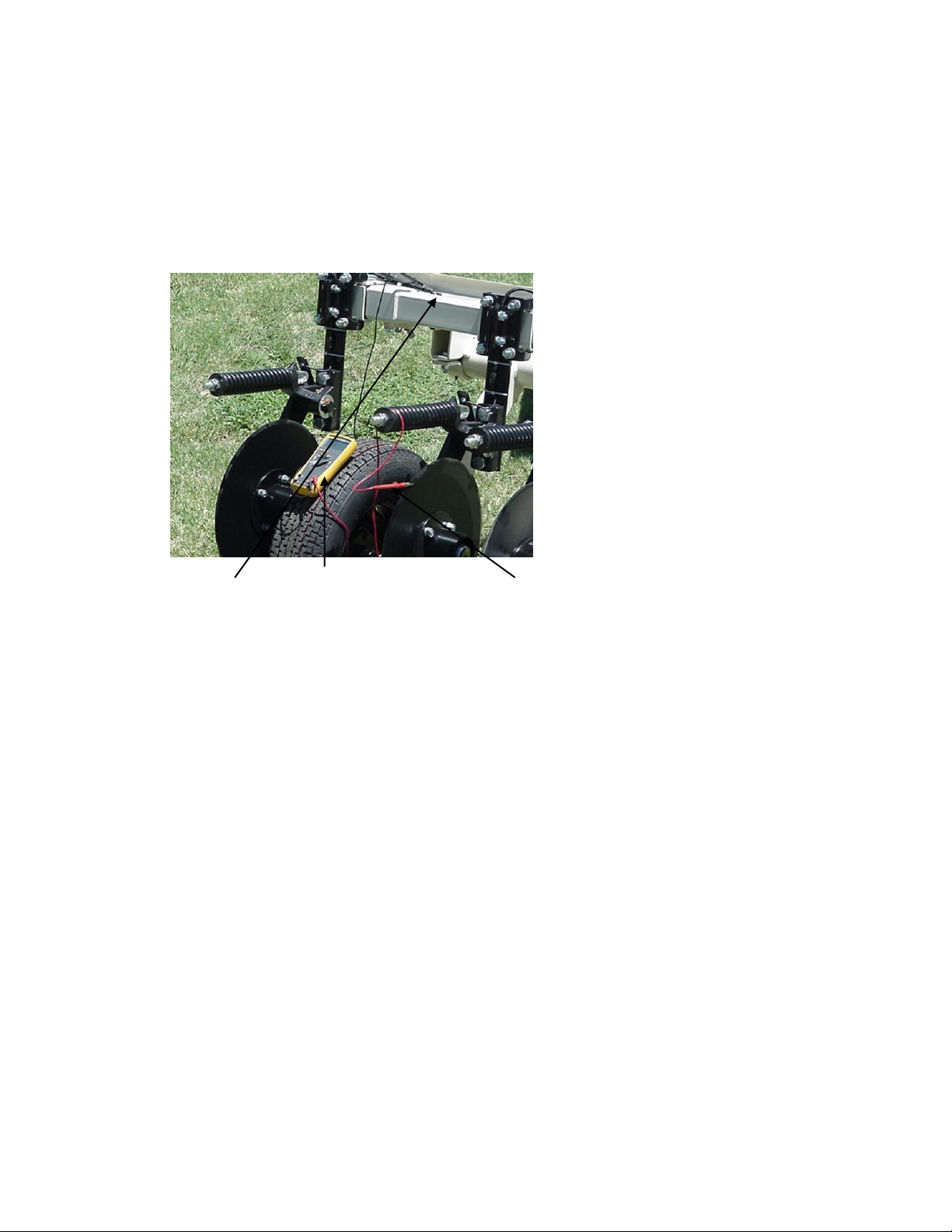
3) Implement Test Box – To properly measure conductivity, good electrical continuity must
be present from the coulter electrode to the instrument. The Implement Test Box (Part
No. 15231) allows you to quickly check this.
Use the following method:
a) Connect the signal cable to the terminal on the test box.
b) Touch one lead of an ohmmeter to the #1 coulter blade (left hand, standing behind
the unit) and the other lead to the #1 terminal on the test box. A reading of less than
2 ohms is normal.
c) Continue to check each coulter electrode in succession, left to right.
d) If any coulter electrode exhibits no continuity or resistance higher than 2 ohms, refer
to the maintenance or trouble shooting sections for possible causes.
Page 7

Veris Technologies
7
Pub. #OM 1CM02-1
Note: It is advisable to perform this test on a routine basis (weekly or every 20-25 hours
of data collection) to ensure you are obtaining reliable data.
4) Hitch height—adjust hitch on implement so implement operates level when coulter
electrodes are 1-2” in the soil. The hitch is designed with four possible height positions.
Maintenance and Lubrication
Proper maintenance and lubrication of the Veris Soil Sensor Cart will greatly extend the useful life of
the unit, and Veris Technologies strongly suggests that you follow the following guidelines:
LUBRICATION
Rockshaft pivot points – Each pivot (left and right) contains an upper and lower grease zerk.
Due to the limited motion of the rockshaft, these should be lubricated
on 40-hour intervals.This may vary based on the number of times
the unit is raised and lowered.
Page 8

Veris Technologies
8
Pub. #OM 1CM02-1
Pivot grease zerks
Rachet jack -- 40 hour intervals
Grease zerks
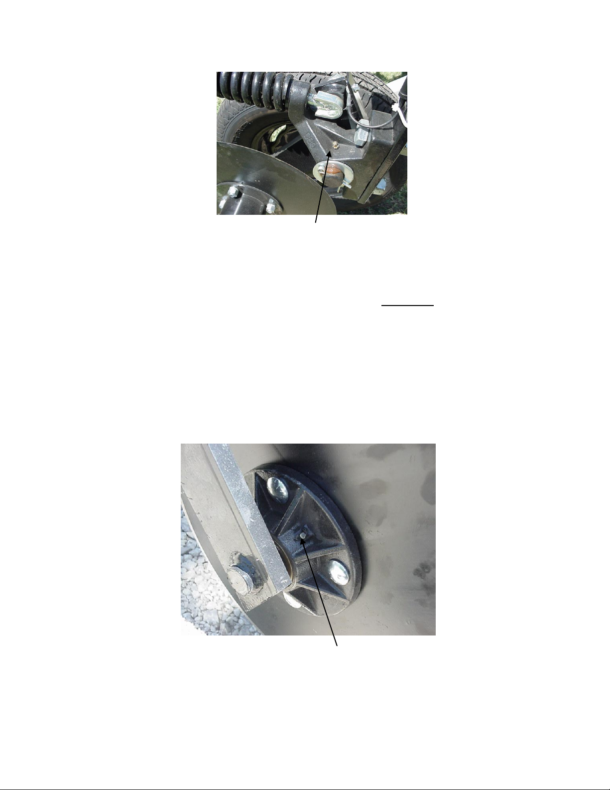
Electrode coulters
Pivot -- In all but the most extremely rocky conditions, the coulter electrodes should
not flex in the field, thus minimal movement will be realized at the pivot.
80-hour intervals should be sufficient.
Page 9
Veris Technologies
9
Pub. #OM 1CM02-1
Grease zerk
Hubs -- Use good quality wheel bearing or lithium grease for lubrication, but we
suggest that you grease the hubs sparingly. Over-lubricating the hub
will result in pre-mature seal failure, and an excessive amount of grease
in the hub cap/commutator. On an interval of 150 hours, 1-2 strokes of
grease should be sufficient.
Coulter Hub
Grease zerk
ADJUSTMENTS
Page 10

Veris Technologies
10
Pub. #OM 1CM02-1
Commutators-- The spring-loaded commutators are located in the center of each coulter
electrode hub cap. They are factory preset, and should not need
routine adjustment. If a continuity test shows abnormally high resistance,
the commutators should be checked. This may be performed in the following
manner:
1) Remove the 3/8” allen head set screw.
2) Remove the commutator by turning counter-clockwise.
3) Depress the spring loaded tip on a hard surface to determine if
plunger has adequate tension and can move freely.
4) If the plunger will not move freely, replace, and coat with di-electric
silicone grease.
5) If the commutator appears to be in good working order, reinstall in the
hub, and adjust until it bottoms against the spindle end. Rotate 1/2 turn
backward to allow adequate clearance. Improper adjustment will result in
premature failure (too little tolerance) or poor continuity (too much
tolerance).
6) Reinstall locking set screw and tighten firmly on top of commutator. The
top of the set screw should be even with the face of the hub. If not,
remove and adjust the commutator inward or outward as necessary.
7) Re-test coulter electrode continuity.
Here is a cut away view of the hubcap assembly
Page 11

Veris Technologies
11
Pub. #OM 1CM02-1
Cap Commutator Set screw Spindle
Note: If you are still unable to obtain favorable resistance readings, check for
excessive corrosion at the coulter blade mounting bolts, or the terminal located
near the coulter pivot.
ANNUAL MAINTENACE
Wheel hubs -- On and annual basis, disassemble, clean, and properly repack the wheel
hubs with suitable wheel bearing grease. It is advisable to replace the seals.
As with any tapered roller bearing, proper pre-load will extend the
life of the assembly. Fully tighten the nut, then rotate backward up to ¼
turn, so that the hub turns freely, without endplay. Install cotter pin, and
reinstall hub cap.
Coulter electrode
hubs -- The coulter electrode hubs operate in a significantly harsh environment,
and annual inspection is of utmost importance. The double-lip seals are
designed to keep grease in, and contaminates out, but they are the cause of
practically all hub failures. It is advisable to disassemble, clean, repack, and
re-install annually. To perform this maintenance, do the following:
1) Remove hub cap by turning in a clockwise direction (left-hand thread
prevents loosening in operation).
2) Remove cotter pin, castle nut, thrust washer, and remove hub.
3) Remove outer bearing and knock out inner bearing using a wooden
dowel or brass rod. Be sure to match each bearing to its location on the
hub and do not mix bearings between hubs. Natural wear will cause the
bearing and race to form pattern that is unique to that set.
4) Thoroughly wash hub and bearings in solvent and dry.
5) Replace bearings and races that show excessive wear or pitting.
6) Pack with grease, and reassemble -- or reassemble, and pack via grease
zerk with wheel bearing or lithium grease. It is advisable to replace the
seals.
7) Adjust bearing pre-load as mentioned above. Excessive pre-load may
cause plugging in extremely loose soil conditions, and excessive endplay
may damage the commutators.
8) Inspect the sealing o-ring on the hub cap, and reinstall by threading
counter-clockwise on the hub.
9) Adjust commutator clearance as mentioned on page 8.
Hub Thrust washer Seal Nut Bearing
Page 12

Veris Technologies
12
Pub. #OM 1CM02-1
Swing arm
Field Operations
Soil Contact
Begin field operation by lowering unit into soil. For good electrical conductivity, all coulter electrodes
must be in direct contact with the soil, at all times and in every region of the field. A depth of 1-2” is
recommended. To insure this depth is consistently achieved, 300-350 lbs. of additional weight are
normally required. Veris offers optional weights and mounting hardware that can be installed on the
2000XA. Do not adjust the tension on the coulter electrode springs to increase soil contact or
penetration. They are pre-set at the factory with the proper tension.
Speed
Proper field operating speed depends on field conditions. Because of the importance of consistent
contact, the unit must not be allowed to bounce over rough fields at high speeds. On smooth fields,
the implement can be operated at speeds from 8-12 m.p.h. Reduce speeds in rocky conditions.
Page 13

Veris Technologies
13
Pub. #OM 1CM02-1
Field Condition
Field should be in a uniform state. Mapping after intensive primary tillage is not recommended. The
soil must have a minimum of 10% available water, and cannot be frozen. If rocky conditions exist, you
may wish to consider the optional coulter rock guard kit , PN 15170.
Pulling Vehicle
The 2000 XA, with its small size and low draft requirement, is designed for ATV use, yet may be
pulled with a variety of vehicles: 4x4 ATV (400cc or larger), small compact tractor, compact or fullsized pickup. Veris suggests that the unit be loaded for road transport.
Swath width and Navigation
Setting the swath width and navigation system is at the discretion of the customer. A 40-60’ swath
works well in most areas. In areas of high soil variability, a narrower swath may be preferred.
Several methods of navigation are possible: following previous crop rows, flagging the field, or using
a field navigation computer. While it is important to map in a consistent pattern, it isn’t absolutely
critical that each pass be exactly the same distance from the previous pass.
Array Selection
The 2000 XA , in the narrow (shallow) configuration, with the adjustable toolbar fully retracted will
investigate the top 2’ of soil. In the wide, fully extended configuration, the array will penetrate 0-3’ of
soil. Adjustment is made by loosening the jam nuts and set screws located on the lower front of each
side of the toolbar, adjusting the toolbar wing extensions, and re-tightening the set screws. Veris
suggests setting the toolbars at either the maximum or minimum setting, not at a point in between. A
limiter bolt determines full extension, so there should be no danger of extending to the point at which
the outside coulters disconnect from the main frame. Important – do not attempt to combine maps in
which two different investigative depths are used.
Set Screws Narrow Setting
Page 14

Veris Technologies
14
Pub. #OM 1CM02-1
Wide Setting
GPS Settings
1. Make sure that the GPS is plugged into the proper DB-9 input. Looking at the back of the
instrument, the GPS should be plugged into the leftmost input port. A null modem adapter should
not be used.
2. Make sure that the GPS has power and has been turned on long enough to start outputting data.
Some units may require a couple minutes to start while others may require much longer.
3. Make sure the GPS output is at 4800 baud, 8 data bits, no parity and 1 stop bit. (note: set parity
to “None”, not “zero”)
4. Make sure the GPS is set to output NMEA-0183 messages that include the GGA and VTG or
RMC string. The GGA string provides the position and fix quality while the VTG or RMC string
provides the speed. Make sure the update rate is set at 1 Hz.
5. If your settings appear correct, but the position still does not appear on the Veris instrument, use
a laptop to monitor the GPS signal to verify its integrity. If the signal appears properly on a
laptop, it should work on the instrument as well.
Page 15
Veris Technologies
15
Pub. #OM 1CM02-1
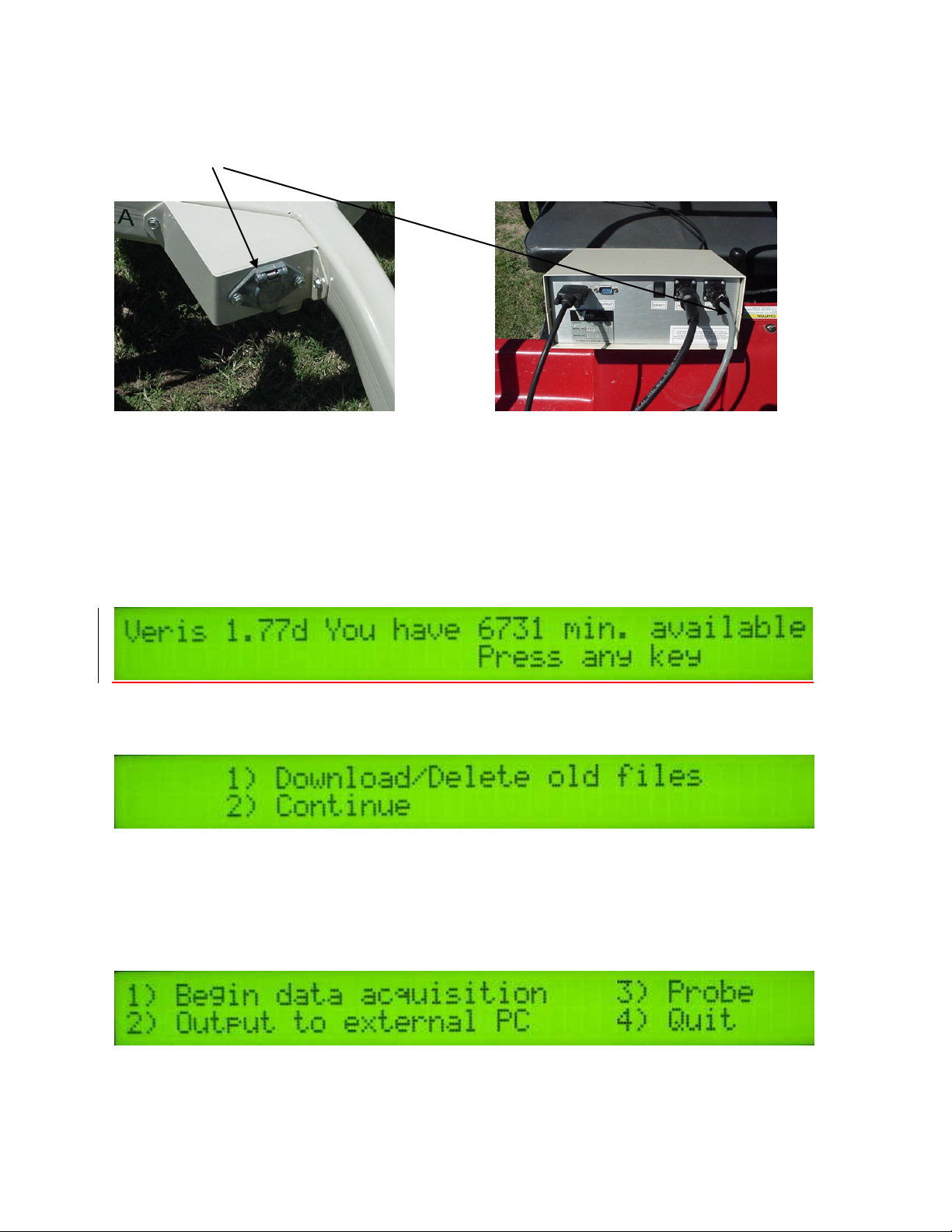
Signal Cable
Attach the signal cable to the quick connect coupler at front of frame, and to Signal Port on back of
instrument
Instrument display readings
Here are the display readings that you will see when operating the system, the meaning of each, and
what choices you have at each step.
Booting up…
Meaning: The unit is ready to operate. The computer is informing you of how much of its internal
memory is available. Check available minutes to be sure you have enough available memory to
contain the data from field you are about to map.
Choices: Press any key
Meaning: You are being given a choice between downloading/deleting map files you have made
previously, or starting a new map file.
Options: 1. Download/Delete old files: For information on Option 1, see section on File
Management, p.7.
2. Continue: Pressing this key will bring up the next display and continue the process of
creating a new map file.
Creating a new map file…
Meaning: The unit is asking whether you’re ready to start mapping.
Choices: If you press 1, you’ve initiated the beginning of a map file. Command #2 is for sending a
data string to a second data-logging device. (The conductivity output format is 9600 baud, 8 data bits,
Page 16

Veris Technologies
16
Pub. #OM 1CM02-1
no parity and 1 stop bit. A null modem adapter is required.) If you press 3, the system will tell you it’s
ok to shut off power.
Meaning: The unit is letting you know the name of the map file it is creating, in case you want to
record it along with any other information about the field.
Choice: Press any key to begin new map file (after starting the file, pressing any key will stop the file)
Meaning: The unit is telling you the latitude and longitude of your position, the conductivity of the
top 1’ and top 3’ of the soil, relative elevation, and whether you have GPS or DGPS (differentially
corrected) signal. The system does not record: 1) any conductivity point that isn’t DGPS georeferenced, 2) any point that has negative numbers in both the shallow and deep arrays, and 3) any
data when the machine is not moving.
There are warning signals programmed into the Veris instrument to warn the operator that one or
more of these conditions exist, so that corrective action can be taken. If any of these conditions exist,
a warning alarm will sound, and the portion of the screen text that is missing information will blink.
For example, if the DGPS isn’t being received (or the NMEA string containing speed) the Lat/Long
text will blink.
Choices: At any time during the mapping process, you can press any key to stop the file. If you
create more than one file from the same field, you can bring the files into a spreadsheet program and
combine them prior to mapping.
If no data is saved during Data Acquisition, the following screen will be displayed:
If data was collected and saved to a file during Data Acquisition, the following screen will be
displayed:
This means files were saved to both the Instrument’s memory and to the removable memory card
during Data Acquisition.
File management
Data is stored in the Veris instrument on a flash memory chip and simultaneously on a removable
CompactFlash (CF) card. The File Management option is used to re-copy data files from the
instrument’s flash memory to the CF card and to delete files from either the instrument or the CF
card.
If any old data files are present on the Instrument, pressing any key at the main title screen will bring
up the following screen:
Pressing 1 will proceed into managing the files on the Instrument and CF card. Pressing 2 will
continue to the main menu.
Page 17
Veris Technologies
17
Pub. #OM 1CM02-1
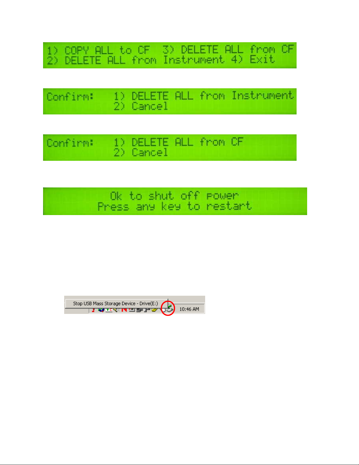
This is the File Management menu. Pressing 1 will copy all data files present on the Instrument to the
removable CF card.
Pressing 2 will bring up the following screen:
Selecting 1 will delete ALL data files from the Instrument. Verify that all data files are backed up to a
computer before proceeding.
Pressing 3 in the File Management menu will bring up the following screen:
Selecting 1 will delete ALL data files from the CF card. Verify that all data files are backed up to a
computer before proceeding.
If you choose to quit, the display will read:
To copy files from the CF card to a PC, turn off the instrument and remove the CF card from the
Instrument by pressing the black button located under the drive door. The card will spring free.
Use the included USB CF card reader to transfer files from the CF card to your computer. Before
transferring files for the first time, follow the manufacturer’s directions for installing any necessary
drivers for the USB reader.
Follow these steps to transfer files from the CF card to your computer:
1) Shut off your instrument. Always turn the instrument off before removing the CF card.
2) Remove the CF card from the instrument and insert it into the USB reader.
3) Connect the USB reader to your computer.
4) Transfer the data files from the CF card to your computer using File Manager.
5) Left mouse click on the green arrow in your computer’s system tray and again on the button
“Stop USB Mass Storage Device”.
6) Click “OK” on the window that appears. It is now safe to remove the card reader from your
computer and re-insert it in to your instrument.
**NOTE: The instrument WILL NOT function without the CF card inserted. If the
instrument is turned on without the CF card inserted, the display will only show black bars
on the first line. If this occurs, shut down the instrument, insert the CF card, and restart
the Instrument.
**NOTE: DO NOT leave the CF card and USB card reader connected to your computer when
shutting down or restarting your computer.
Page 18

Veris Technologies
18
Pub. #OM 1CM02-1
TROUBLESHOOTING
Map doesn’t match known or expected soil types --
1. Check electrical continuity using Implement Test Box as discussed on Page 6.
2. Check isolation of coulter electrodes (pg. 5)
3. Map additional fields to see if similar condition results
4. Contact Veris Service Department
No conductivity readings on instrument display--
1. Check for excessive corrosion on coulter terminasl.
2. Check for broken signal wire by disconnecting wire from coulter electrode and checking
continuity from end of wire to corresponding terminal on test box. Replace coulter wiring (PN
15601) or signal cable (PN 13602) as required.
3. Check for collapsed spring-loaded commutators.
Data missing from display reading –
1. Unit must be in contact with soil to record data points; lower unit or add weights to ensure
consistent 1”-2” penetration into soil
2. Check GPS and DGPS signal; Veris instrument is programmed to eliminate all non-DGPS georeferenced points.
3. Shut power off and restart
4. Check electrical continuity: coulter electrodes to terminal…terminal to instrument.
5. Check input voltage, 12 v minimum required
Excessive number of negative readings in data --
1. Increase depth of penetration.
2. Slow down in extremely rough fields.
3. Alter transect pattern to avoid areas of heavy residue (combine swath)
Instrument has “locked up” and is not responding --
1. Shut off power and restart. Download the file that you were creating at the time the problem
occurred. Continue mapping the field. The files can be combined later in your spreadsheet.
2. Check for flash card in drive. Always start up the instrument with the proper flash card inserted in
the drive.
File will not download –
1. Try again
2. Check to see if you are receiving DGPS signal; system eliminates all non-DGPS geo-referenced
points
3. Restart computer and try again
Troubleshooting GPS Problems--
This is a problem-solving guide for the user who is not able to obtain a position from the GPS when it
is connected to the Veris instrument. Note that when the system is working properly, the latitude and
Page 19

Veris Technologies
19
Pub. #OM 1CM02-1
longitude should appear on the instrument display and the instrument should not beep when the
vehicle is in motion (provided the conductivity readings are positive).
Troubleshooting steps
6. Make sure that the GPS is plugged into the proper DB-9 input. Looking at the back of the
instrument, the GPS should be plugged into the leftmost input. A null modem adapter should not
be used.
7. Make sure that the GPS has power and has been turned on long enough to start outputting data.
Some units may require a couple minutes to start while others may require much longer.
8. Make sure the GPS output is at 4800 baud, 8 data bits, no parity and 1 stop bit. (note: set parity
to “None”, not “zero”)
9. Make sure the GPS is set to output NMEA-0183 messages that include the GGA and VTG or
RMC string. The GGA string provides the position and fix quality while the VTG or RMC string
provides the speed. Make sure the update rate is set at 1 Hz.
10. If your settings appear correct, but the position still does not appear on the Veris instrument, use
a laptop to monitor the GPS signal to verify its integrity. If the signal appears properly on a
laptop, it should work on the instrument as well. To do this,
a) plug the GPS output into the laptop serial input and then start the “HyperTerminal” program
under “Accessories” in Windows.
b) click on the icon called “hypertrm.exe” to establish a connection.
c) Type in “gps” when the program prompts you for the name of your connection and then hit
“OK”.
d) The program will then ask you for a phone number. Instead of entering a phone number,
specify the proper serial port number. For example, if Com 1 of the laptop is being used,
specify “Direct to Com 1” under “connect using:” at the bottom of the entry area.
e) HyperTerminal will then display a configuration menu where you can specify 4800 bits per
second, 8 data bits, no parity, 1 stop bit and no flow control.
At this point, upon clicking ok, legible strings of GPS data should begin appearing on the laptop
screen. Here’s an example of a typical set of strings:
$GPGGA,191528.00,3851.0333,N,09737.2342,W,2,08,1.3,372.7,M,27.3,M,10.0,0100*69
$GPGSA,A,3,09,23,21,17,08,01,03,29,,,,,2.6,1.3,2.3*39
$GPRMC,191528.00,A,3851.0333,N,09737.2342,W,0.1,0.0,090998,6.3,E*48
If GPS data doesn’t appear, recheck the port and configuration settings to make sure they are
correct. If the data won’t appear correctly in HyperTerminal, consult your GPS supplier to see
what adjustments (connectors or software) are necessary to bring the signal into a computer. On
the other hand, if the signal appears correctly on HyperTerminal and it shows that the required
strings are being output, retry the unit with the Veris instrument. If it still doesn’t work, please call
Veris at 785-825-1978 to see how we can help solve the problem.
Page 20
Veris Technologies
20
Pub. #OM 1CM02-1
CF card Troubleshooting:
Using off-the-shelf CF cards rather than the ones supplied by Veris Technologies, may cause any of
the following problems:
-instrument won’t boot up
-instrument won’t log any data
-GPS signal not recognized
Veris CF cards contain an ATA front end--circuitry that makes the CF card look like a hard drive
to the instrument. Most CF cards don't have this. Some do contain ATA front ends, however this
information is not typically listed on after-market cards. The Veris CF card also has a higher
temperature rating than other CF cards and will take more heat generated by the instrument in
the summer time.
Updating Instrument Firmware
Steps for updating the Veris Instrument firmware:
1. Shut Instrument off and remove CompactFlash card. Always turn the instrument off
before removing the CF card.
2. Insert CompactFlash card into CompactFlash card USB reader.
3. Plug USB reader into computer.
4. Copy the file VERIS.EXE from your computer to the CompactFlash card.
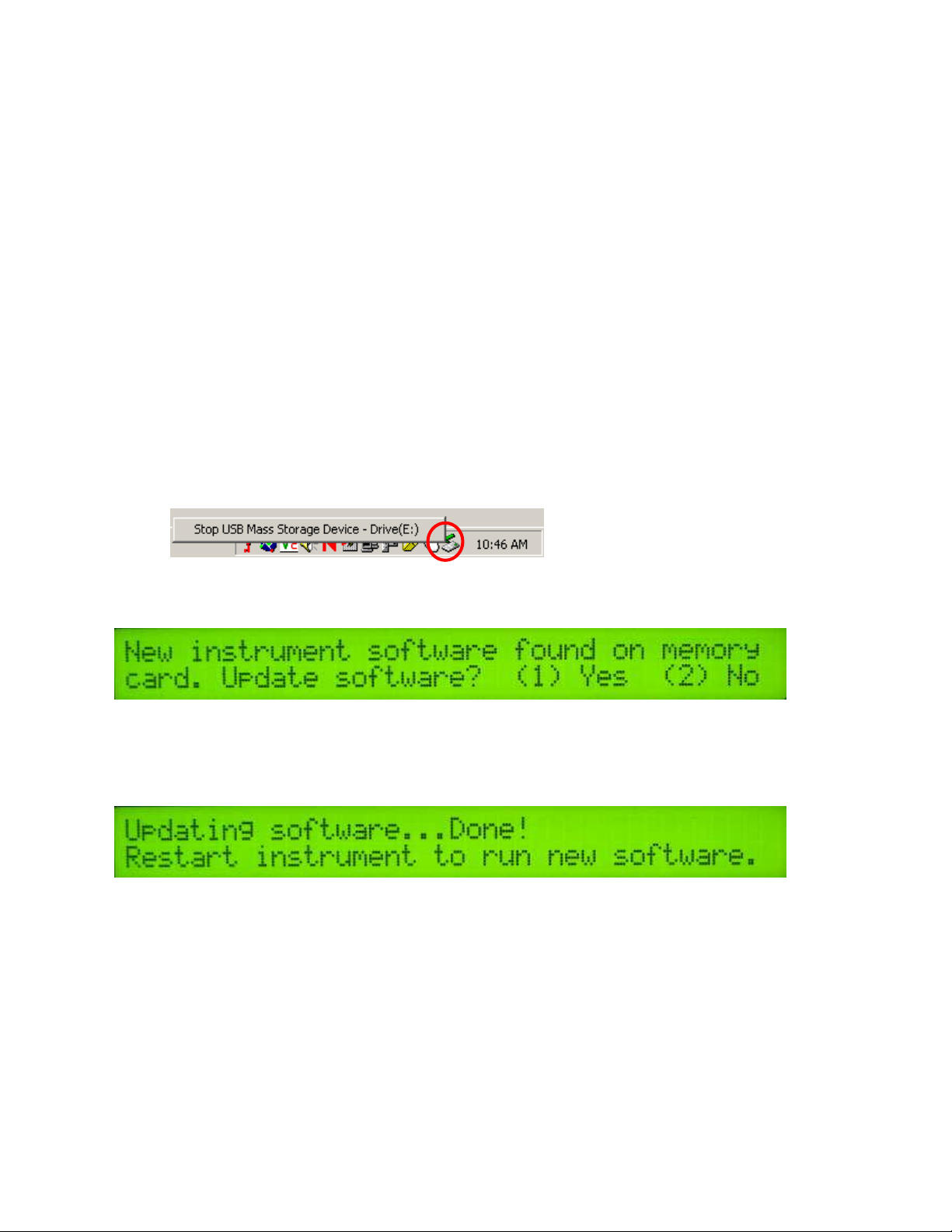
5. Left mouse click on the green arrow in your computer’s system tray and again on the button
“Stop USB Mass Storage Device”.
6. Click “OK” on the window that appears. It is now safe to remove the card reader from your
computer.
7. Insert CompactFlash card into the Instrument and restart the Instrument. During bootup, the
following screen will appear:
**NOTE: The instrument WILL NOT function without the CF card inserted. If the
instrument is turned on without the CF card inserted, the display will only show black bars
on the first line. If this occurs, shut down the instrument, insert the CF card, and restart
the Instrument.
8. Press (1) to continue with the update procedure. Press 2 to continue to the main title screen.
9. After the Instrument is done updating, the following screen will appear:
10. Restart the Instrument. The new firmware will be running. During the update process, the
VERIS.EXE file is deleted from the CompactFlash card so these screens will not be seen
when the Instrument restarts.
Running Utility Files
Utility files can be run from the CompactFlash card to perform various tasks. Here are the general
instructions for running utility files:
1. Shut Instrument off and remove CompactFlash card. Always turn the instrument off
before removing the CF card.
2. Insert CompactFlash card into CompactFlash card USB reader.
3. Plug USB reader into computer.
4. Copy the file VERIS.BAT from your computer to the CompactFlash card.
Page 21
Veris Technologies
21
Pub. #OM 1CM02-1
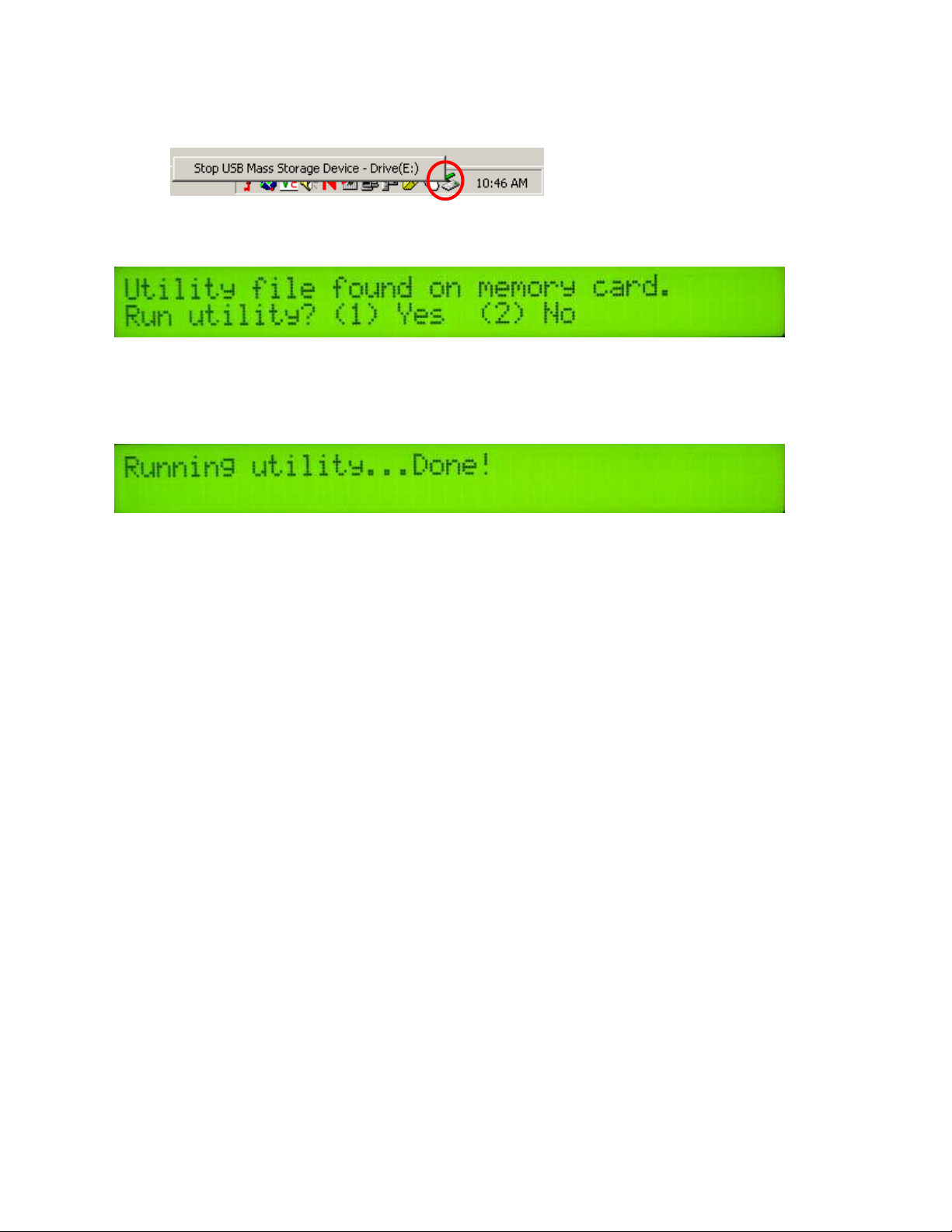
5. Left mouse click on the green arrow in your computer’s system tray and again on the button
“Stop USB Mass Storage Device”.
6. Click “OK” on the window that appears. It is now safe to remove the card reader from your
computer.
7. Insert CompactFlash card into the Instrument and restart the Instrument. During bootup, the
following screen will appear:
**NOTE: The instrument WILL NOT function without the CF card inserted. If the
instrument is turned on without the CF card inserted, the display will only show black
bars on the first line. If this occurs, shut down the instrument, insert the CF card, and
restart the Instrument.
8. Press (1) to continue with the update procedure. Press 2 to continue to the main title screen.
9. After the utility is complete, the following screen will appear:
The Instrument will continue to the main title screen in a few seconds.
Instructions follow for specific utility files:
Set Instrument Time and Date
On your PC:
1. Right-click on the file named VERIS.BAT in the time and date directory.
2. Select Edit from the menu that appears.
3. Follow the instructions at the beginning of the file for changing the time and date listed.
4. Select File and Save from the toolbar.
5. Close the file and follow the directions above for changing the Instrument’s time and date.
Page 22
Veris Technologies
22
Pub. #OM 1CM02-1
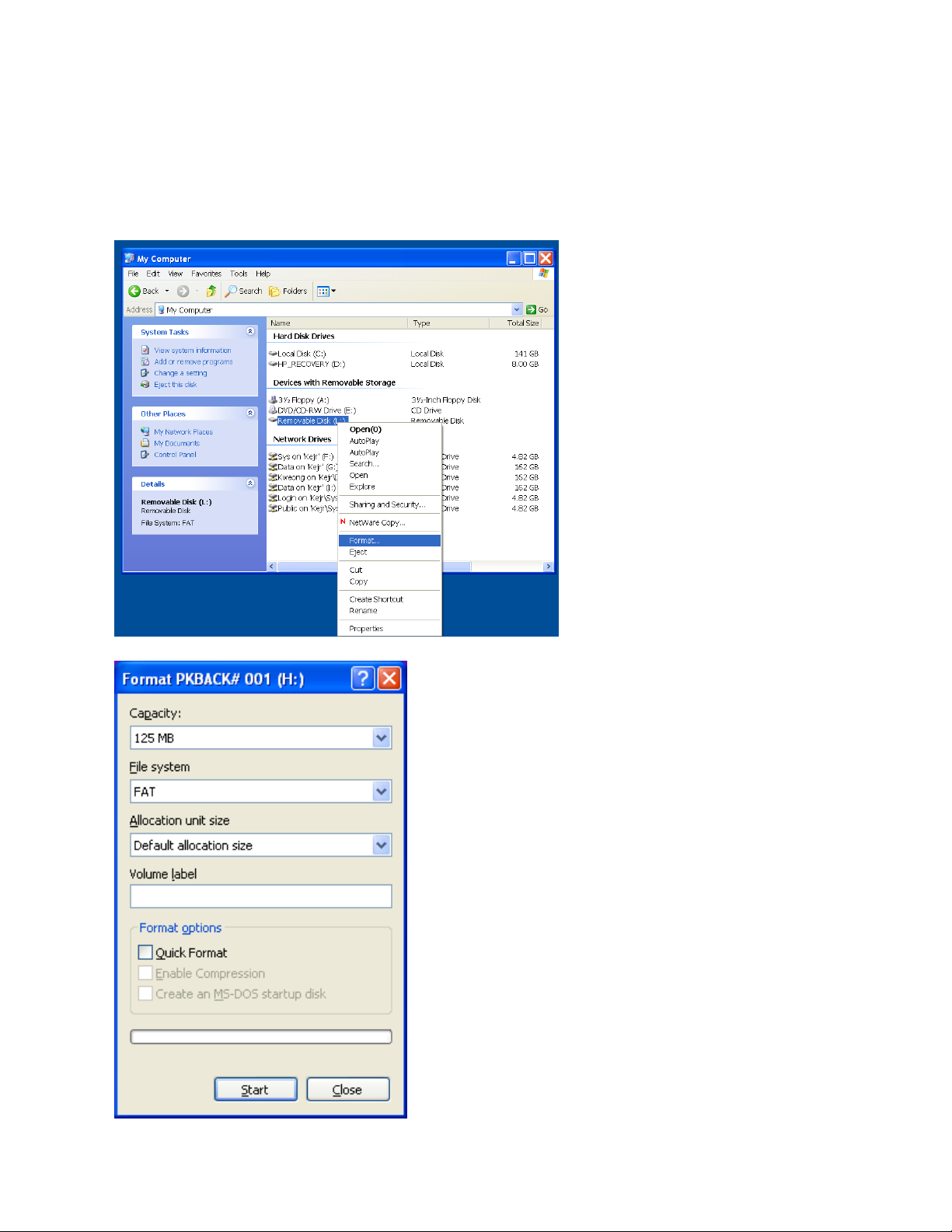
Compact Flash card formatting
Insert a Compact Flash card into a CF card reader which connected to your
computer.
Open “My Computer” folder. Right click on the CF card icon, and select the “Format”.
In the format window, click on the file system
tab and select “FAT” not “FAT32”.
Then press “Start”.
When complete, remove the card.
 Loading...