


 Loading...
Nextiva S1900e Series
User Guide
Covering the S1900e-AS, S1950e, S1970e,
and S1970e-R
Firmware Release 4.80/5.0
March 2009
Unauthorized use, duplication, or modification of this document in whole or in part without the written consent of Verint Systems Inc. is strictly prohibited.
By providing this document, Verint Systems Inc. is not making any representations regarding the correctness or completeness of its contents and reserves the right to alter this document at any time without notice.
Features listed in this document are subject to change. Please contact Verint for current product features and specifications.
All marks referenced herein with the ® or TM symbol are registered trademarks or trademarks of Verint Systems Inc. or its subsidiaries. All rights reserved. All other marks are trademarks of their respective owners.
© 2009 Verint Systems Inc. All Rights Reserved Worldwide. www.verint.com/videosolutions
Publication date: March 11, 2009 Publication revision: C
Contents
Preface ................................................................................................................ |
v |
Chapter 1 Overview .......................................................................................... |
1 |
About the S1900e Series ................................................................................... |
2 |
Key Features .............................................................................................. |
2 |
Video Analytics ........................................................................................... |
3 |
Receiver Modes .......................................................................................... |
3 |
Security ..................................................................................................... |
3 |
Frame Rate and Performance ........................................................................ |
3 |
Installation Kit ................................................................................................. |
6 |
Hardware Overview .......................................................................................... |
7 |
Chapter 2 Configuring and Installing the Device ............................................... |
8 |
Installing the Device ......................................................................................... |
9 |
Connecting Power ....................................................................................... |
9 |
Installing the S1900e ................................................................................ |
11 |
Performing Serial Connections .................................................................... |
11 |
Configuring the Device .................................................................................... |
13 |
Setting Network Parameters ....................................................................... |
13 |
Performing a Point-to-Point Connection ........................................................ |
15 |
Configuring the I/Os ....................................................................................... |
17 |
Alarms .................................................................................................... |
18 |
Audio ...................................................................................................... |
18 |
Data Transmission................................................................................ |
18 |
Audio Input/Output Types ..................................................................... |
19 |
Specifications ...................................................................................... |
20 |
Chapter 3 Using the Web Interface ................................................................. |
21 |
Installing or Upgrading ActiveX Controls ............................................................ |
22 |
Viewing the Quick Status ................................................................................. |
24 |
Configuring the Device .................................................................................... |
26 |
Configuring the Serial Port ......................................................................... |
26 |
Configuring Access Management ................................................................. |
27 |
User Accounts...................................................................................... |
27 |
Security .............................................................................................. |
29 |
Viewing the System Status ......................................................................... |
31 |
Configuring the Network ............................................................................ |
32 |
Configuring Video ..................................................................................... |
33 |
General Parameters for Transmitters....................................................... |
33 |
Encoder .............................................................................................. |
34 |
General Parameters for Receivers ........................................................... |
39 |
Decoders............................................................................................. |
42 |
Looking at Video Status ............................................................................. |
43 |
Configuring VSIP ....................................................................................... |
44 |
Configuring Audio ..................................................................................... |
45 |
Configuring System Time ........................................................................... |
47 |
Configuring On-Screen Display ................................................................... |
48 |
Configuring HTTP (Webserver) .................................................................... |
52 |
Verint Video Intelligence Solutions |
3 |
Contents |
|
Viewing Live Video .......................................................................................... |
53 |
Configuring Live Video ............................................................................... |
53 |
Manipulating the PTZ Camera ..................................................................... |
57 |
Maintaining the Device .................................................................................... |
58 |
Chapter 4 Maintaining and Troubleshooting the Device ................................... |
61 |
Updating the Firmware .................................................................................... |
62 |
Performing a Reset ......................................................................................... |
62 |
Losing Connection to a Camera ......................................................................... |
63 |
Recognizing the Status LED Conditions .............................................................. |
63 |
Using the Command Line Interface .................................................................... |
64 |
Accessing the CLI ...................................................................................... |
64 |
Configuring Quality of Service ..................................................................... |
66 |
Appendix A Factory Default Configuration........................................................ |
67 |
Appendix B DHCP Support and APIPA .............................................................. |
69 |
Appendix C Audio Pinouts ................................................................................ |
71 |
Appendix D Technical Specifications ................................................................ |
73 |
Glossary ............................................................................................................. |
76 |
Index ................................................................................................................. |
81 |
Compliance ........................................................................................................ |
84 |
United States Statement for FCC ...................................................................... |
85 |
Industry Canada Statement ............................................................................. |
85 |
Europe EN 55022 Statement ............................................................................ |
86 |
RoHS Declaration of Compliance ....................................................................... |
87 |
4 |
Verint Video Intelligence Solutions |
Preface
The Nextiva S1900e Series User Guide presents the information and procedures on installing, configuring, and using the Nextiva® S1900e series edge devices.
This guide covers the following firmware versions:
Edge Device |
Version |
|
|
S1900e-AS |
5.0 |
|
|
S1950e |
4.80 |
|
|
S1970e |
4.80 |
|
|
S1970e-R |
5.0 |
|
|
Audience
This guide has been prepared for the following audience:
Managers
IT system administrators
Engineers
Technicians
This guide assumes that you are familiar with:
Installation and manipulation of electronic equipment
General use of computers
Local area networks (LANs) and basic IP data communication concepts and practices
Pan-tilt-zoom (PTZ) platforms (cameras and keyboards)
Web browsers
Microsoft Windows operating systems
Reference
In addition to this guide, the following documentation is also available:
Nextiva S1900e Series Installation Guide
Verint SConfigurator User Guide
Nextiva S1900e-AS Release Notes
Nextiva S1950e S1970e Release Notes
Nextiva S1970e-R Release Notes
A paper copy of the installation guide is included with your order.
Verint Video Intelligence Solutions |
v |
Preface
How to Contact Us
The following Web sites and e-mail addresses provide information and support for Verint Video Solutions and the Nextiva Intelligent Edge Device product line.
Find general information on Verint Video Solutions, including marketing material and product information at www.verint.com/videosolutions.
Download the documentation of the Intelligent Edge Devices at www.verint.com/manuals.
Download firmware from the Verint Video Solutions partner extranet at http://vvs.verint.com.
Send your questions or comments on the current document, or any other Nextiva user documentation, to our documentation feedback team at documentationfeedback@verint.com.
Find contact information for the Verint Customer Service team, by phone or e-mail, or fill out a Web request for support with a specific issues at www.verint.com/videoservice. For immediate assistance, contact the Customer Service team:
Location |
Telephone |
||
|
|
|
|
USA and Canada |
1-888-747-6246 |
vissupport@verint.com |
|
|
|
|
|
Central and Latin |
+1-631-962-9202 |
vissupport@verint.com |
|
America |
|
|
|
|
|
|
|
Europe, Middle East, |
+44 (0) 845-843-7333 |
customersupport.emea@verint.com |
|
and Africa |
|
|
|
+49 (0) 4321-269 81 36 |
mobilesupport@verint.com |
||
|
|||
|
|
(Transit applications only) |
|
|
|
|
|
Asia/Pacific |
|
APAC_VIS_Services@verint.comp |
|
Hong Kong |
+852 2797 5678 |
|
|
Singapore |
+65-68266099 |
|
|
|
|
|
Warranty
Each product manufactured by Verint Video Solutions Inc. is warranted to operate substantially in accordance with the end user documentation delivered with the product for the period indicated in the applicable Verint Product Guide. Verint shall have no responsibility or liability of any kind, whether for breach of warranty or otherwise, arising or resulting from errors resulting from misuse, abuse, negligence, or improper use or installation of all or any part of the product, or problems to or caused by products or services not provided by Verint. Verint shall have no responsibility for product modifications or changes by any party other than Verint or Verint’s representative expressly authorized to make such modification or change. The customer’s exclusive remedy under this warranty shall be for Verint, in its sole discretion to use commercially reasonable efforts either to correct any verifiable material nonconformity or to replace the materially nonconforming portion of the product. Verint provides all third party hardware on an “AS IS” basis without warranties of any kind, unless Verint specifies otherwise. In certain cases, such third party
vi |
Verint Video Intelligence Solutions |
Nextiva S1900e Series User Guide
Hardware may be accompanied by the manufacturer’s own warranty and warranty service must be obtained directly from the third party manufacturer. In the event any Verint product is to be returned to Verint for warranty repair, a return material authorization (“RMA”) must be obtained from Verint prior any return. Transportation charges for return of hardware shall be paid by the customer. All replaced hardware or parts become Verint’s property, except for video or similar data files contained in the hard drive of any product which shall be returned or destroyed at customer’s request. Except as stated above, Verint makes no other warranties, express or implied, relating to the products.
Verint Video Intelligence Solutions |
vii |

Overview
Designed for video monitoring and surveillance over IP networks, the Nextiva S1900e series is a highly compact, single-input or -output edge device.
On the transmitters, the following compression modes (also called codecs—coder/decoder) are available to deliver video over 10/100Base-T networks: a proprietary MPEG-4-based mode, the MPEG-4 ISO 14496-2 compliant mode, and MJPEG (Motion JPEG). The device can easily be extended over local and wide area networks (LANs and WANs) or the Internet using ISDN, PSTN, or xDSL routers. It is built on open standards to provide long-term investment protection.
On the receiver, you have access to three video display modes.
The overview covers the following:
About the S1900e series
Installation kit
Hardware overview
Verint Video Intelligence Solutions |
1 |
Nextiva S1900e Series User Guide
About the S1900e Series
You can use the S1900e series edge devices in point-to-point contexts as well as with video management and storage applications. Furthermore, they enable configuration, live video viewing, and maintenance from web browsers.
The following suffixes may be used in the product names:
-T for transmitters
-R for receivers
When no suffix is used, it is assumed that the device is a transmitter. This device is for indoor use only.
Key Features
The S1900e series devices contains three transmitters and one receiver, covering different video resolution and functionality needs:
Device |
Video I/O |
On-Board |
Camera Tampering |
Power |
|
|
|
Analytics |
Detection |
|
|
|
|
|
|
|
|
S1900e-AS |
1 input |
3 |
3 |
12V |
DC |
|
|
|
|
|
|
S1950e |
1 input |
|
|
12V |
DC |
|
|
|
|
|
|
S1970e |
1 input |
|
|
12V |
DC or power |
|
|
|
|
over Ethernet (PoE) |
|
|
|
|
|
|
|
S1970e-R |
1 output |
|
|
12V |
DC |
|
|
|
|
|
|
The S1900e series offers the following additional features:
A serial port for the RS-422/485 protocol
Dual video encoding on the transmitters
One input contact and one output relay
1/8 inch (3.5 mm) stereo jacks for audio
Default serial port settings compatible with the most popular camera data port configuration (4800 baud, 8 data bits, no parity, 1 stop bit)
Integration with the Nextiva enterprise video management solution
You can also purchase each device with the extended temperature option (the S1900e-AS-XT, S1950e-XT, S1970e-XT, and S1970e-R-XT).
Unless otherwise specified, the word S1900e refers to any of these devices.
Verint Video Intelligence Solutions |
2 |
1: Overview
Video Analytics
The on-board video analytics capabilities of the S1900e-AS can be used inside a Nextiva IntelliView solution. In the IntelliView Analytics Rule Builder, the S1900e-AS supports a maximum of five active rules and six views. For more information, refer to the documentation set of the Nextiva enterprise video management platform.
The analytics license is not included with the device. For details, refer to your Verint representative.
Receiver Modes
The S1970e-R can display video streams coming from up to four transmitters on a single analog monitor, to create a maximum of four different point-to-point connections; you create these connections in SConfigurator (see page 15). You can choose between the following video display modes: solo, quad, and guard tour (for more information, see page 39).
Security
Every edge device comes with a unique SSL (Secure Sockets Layer) certificate for securing its IP link. SSL is a commonly used protocol for managing the security of IP message transmission. If enabled, the SSL protocol secures the following data: I/O, serial port, and VSIP (a proprietary protocol) communication. It does not apply to audio and video transmission.
Frame Rate and Performance
The available video frame rates of each encoder of the transmitter are:
NTSC—1 to 7, 10, 15, or 30 frames per second (fps)
PAL—1 to 6, 8, 12, or 25 fps
The composite signal of a video input is sent to two separate encoders. You can customize each encoder to meet your system needs, for instance in terms of frame rate and resolution. Here are typical scenarios regarding encoder use:
Scenario |
Encoder 1 |
Encoder 2 |
|
|
|
point-to-point |
point-to-point |
unused |
|
|
|
|
unused |
point-to-point |
|
|
|
point-to-point and web interface |
web viewing at rate A |
point-to-point at rate B |
|
|
|
|
web viewing and |
unused |
|
point-to-point at rate C |
|
|
|
|
video management software |
view at rate D |
record at rate E |
|
|
|
3 |
Verint Video Intelligence Solutions |
Nextiva S1900e Series User Guide
Note: You should not use the web interface and a video management software at the same time to avoid configuration conflicts.
The transmitters in the S1900e series can have the following video resolutions:
Resolution |
Number of Columns |
Number of Lines |
|
|
NTSC/PAL |
NTSC |
PAL |
|
|
|
|
QCIF |
176 |
128 |
144 |
|
|
|
|
CIF |
352 |
240 |
288 |
|
|
|
|
2CIF |
704 |
240 |
288 |
|
|
|
|
4CIF |
704 |
480 |
576 |
|
|
|
|
All lines |
352 |
480 |
576 |
|
|
|
|
2/3 D1 |
480 |
480 |
576 |
|
|
|
|
VGA |
640 |
480 |
480 |
|
|
|
|
The following performances can be achieved using single-stream encoding. For dual encoding values, refer to the Nextiva Intelligent Edge Devices Single-Dual Stream Performance document, available on the extranet (Community Links > Technical Briefs > Nextiva Intelligent Edge Devices).
Each video encoder of an S1900e transmitter can have the following performances with the proprietary MPEG-4-based compression mode:
Resolution |
Maximum Frame Rate, in Frames per Second Using the NTSC (PAL) |
||||
|
Format for the MPEG-4-Based Mode |
|
|||
|
S1900e-AS |
S1950e |
S1970e |
||
|
|
|
|
|
|
QCIF |
30 |
(25) |
30 |
(25) |
30 (25) |
|
|
|
|
|
|
CIF |
30 |
(25) |
30 |
(25) |
30 (25) |
|
|
|
|
|
|
2CIF |
30 |
(25) |
30 |
(25) |
30 (25) |
|
|
|
|
|
|
4CIF |
30 |
(25) 1 |
15 |
(12.5) |
30 (25) |
|
|
|
|
|
|
All lines |
30 |
(25) |
30 |
(25) |
30 (25) |
|
|
|
|
|
|
2/3 D1 |
30 |
(25) |
30 |
(25) |
30 (25) |
|
|
|
|
|
|
VGA |
30 |
(25) 1 |
15 |
(12.5) |
30 (25) |
|
|
|
|
|
|
Verint Video Intelligence Solutions |
4 |
1: Overview
1 On encoder 2 only.
Each video encoder of an S1900e transmitter can have the following performances with the MPEG-4 ISO 14496-2 compliant compression mode:
Resolution |
Maximum Frame Rate, in Frames per Second Using the NTSC (PAL) |
||||
|
Format for the MPEG-4 ISO 14496-2 Compliant Mode |
||||
|
S1900e-AS |
S1950e |
S1970e |
||
|
|
|
|
|
|
QCIF |
30 |
(25) |
30 |
(25) |
30 (25) |
|
|
|
|
|
|
CIF |
30 |
(25) |
30 |
(25) |
30 (25) |
|
|
|
|
|
|
2CIF |
30 |
(25) |
30 |
(25) |
30 (25) |
|
|
|
|
|
|
4CIF |
30 |
(25) 2 |
15 |
(12.5) |
30 (25) |
|
|
|
|
|
|
All lines |
30 |
(25) |
30 |
(25) |
30 (25) |
|
|
|
|
|
|
2/3 D1 |
30 |
(25) |
30 |
(25) |
30 (25) |
|
|
|
|
|
|
VGA |
30 |
(25) 2 |
15 |
(12.5) |
30 (25) |
|
|
|
|
|
|
2 On encoder 2 only.
Each video encoder of the S1950e and S1970e transmitter, and the first encoder of the S1900e-AS, can have the following performances with the MJPEG compression mode:
Resolution |
Maximum Frame Rate, in Frames per Second Using the NTSC (PAL) |
||||
|
Format for MJPEG |
|
|
|
|
|
S1900e-AS |
S1950e |
S1970e |
||
|
|
|
|
|
|
QCIF |
30 |
(25) |
30 |
(25) |
30 (25) |
|
|
|
|
|
|
CIF |
30 |
(25) |
30 |
(25) |
30 (25) |
|
|
|
|
|
|
2CIF |
30 |
(25) |
30 |
(25) |
30 (25) |
|
|
|
|
|
|
4CIF |
15 |
(12.5) |
15 |
(12.5) |
30 (25) |
|
|
|
|
|
|
All lines |
30 |
(25) |
30 |
(25) |
30 (25) |
|
|
|
|
|
|
2/3 D1 |
30 |
(25) |
30 |
(25) |
30 (25) |
|
|
|
|
|
|
VGA |
30 |
(25) 3 |
30 |
(25) 3 |
30 (25) |
|
|
|
|
|
|
3 Without noise, I/Os, and other factors affecting quality, the device can achieve the highest frame rate.
5 |
Verint Video Intelligence Solutions |
Nextiva S1900e Series User Guide
On the S1970e-R receiver, the performances for displaying video on an analog monitor vary depending on the video display mode (for more information, see page 39) and the compression mode. The following performances are for the maximum frame rate (NTSC/PAL); the other resolutions and bit rates are also available, with lower frame rates:
Video Display Mode |
Compression Mode |
|
|
|
Proprietary |
MPEG-4 ISO |
MJPEG |
|
MPEG-4-Based |
|
|
|
|
|
|
Solo |
4CIF at 30/25 fps |
4CIF at 30/25 fps |
4CIF at 10/8 fps and |
|
and 6000 kbps |
and 5000 kbps |
40 KBytes |
|
|
|
|
Quad |
CIF at 30/25 fps and |
CIF at 30/25 fps and |
CIF at 10/8 fps and |
|
800 kbps |
800 kbps |
10 KBytes |
|
|
|
|
Guard Tour |
CIF at 30/25 fps and |
CIF at 30/25 fps and |
CIF at 10/8 fps and |
|
800 kbps |
800 kbps |
10 KBytes |
|
|
|
|
Installation Kit
The package contents are:
Item |
Description |
|
|
Transmitter or receiver |
S1900e-AS or S1950e or S1970e or S1970e-R |
|
|
12V DC external power |
A universal power supply for all devices except the S1970e with |
supply |
PoE |
|
|
Printed material |
The Nextiva S1900e Series Installation Guide |
|
|
Option |
|
|
|
Power-over-Ethernet |
An IEEE 802.3af class 3 injector and power cord |
(PoE) kit |
|
|
|
Verint Video Intelligence Solutions |
6 |
1: Overview
Hardware Overview
The S1900e electronics are enclosed in a non-weatherproof aluminum casing that is not meant for outdoor use.
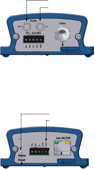
The front panel consists of:
A multipin connector for the RS-422/485 serial port
A pair of 1/8 inch (3.5 mm) I/O audio connectors
One BNC connector for video input or output
Audio output
Audio input
|
|
|
|
|
|
|
|
|
|
|
|
|
|
|
|
|
|
RS-422/485 |
|
Video input or output (S1970e-R) |
|||
|
|||||
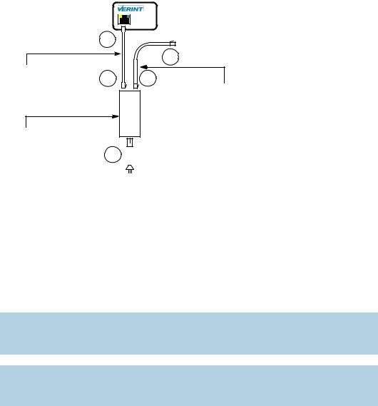
The back panel consists of: |
|
|
|||
A system status LED
12V DC power pins
A reset button
One input contact and one output relay
An RJ-45 jack for the Ethernet network or PoE (on the S1970e only)
System status
12V DC power
Reset |
|
|
|
|
|
|
|
|
|
|
|
|
|
|
|
|
|
|
|
|
|
|
|
|
|
|
|
|
|
|
|
|
|
I/O |
|
|
Network or PoE (RJ-45) |
||
|
|
|
|||||
7 |
Verint Video Intelligence Solutions |

Configuring and
Installing the Device
The steps required to prepare your S1900e device for operation are:
Installation
Basic configuration
I/O configuration
Remember that your device is an indoor product that should not be used in an outdoor environment.
Verint Video Intelligence Solutions |
8 |

2: Configuring and Installing the Device
Installing the Device
The installation process varies depending on the power source, 12V DC or power-over-Ethernet (PoE). Then you may connect the device to serial equipment.
Connecting Power
All devices can use 12V DC for power supply. Verint offers a universal 12V DC power supply as part of your package. For any other power supply, refer to the manufacturer documentation for the proper wiring scheme.
You can also use PoE to power the S1970e transmitter and establish its Ethernet connection. The PoE kit sold by Verint contains two items: an injector and a power cord. The connection procedure may vary if you use another PoE kit; refer to the PoE kit documentation for more information.
Warning: Never use PoE and 12V DC at the same time; otherwise you may damage the device.
To power the device using the universal 12V DC power supply:
1.If the electrical plug installed on the power supply is the right one for the country of operation, go to step 4.
2.Remove the installed plug by pushing the PUSH button and keeping it pushed while turning the plug in the counterclockwise direction.
3.Insert the required plug on the power supply then turn it in the clockwise direction until you hear a click.
4.Plug the power supply wire with the dashed white lines in the Gnd pin on the back of the device.
5.Plug the other power wire in the Pwr+ pin on the back of the device.
6.Connect the electric plug into the outlet.
9 |
Verint Video Intelligence Solutions |
Nextiva S1900e Series User Guide
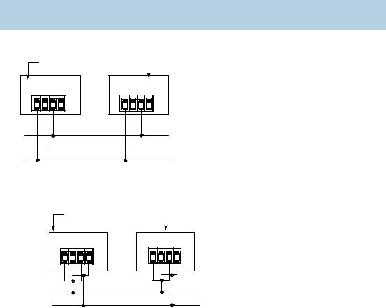
To connect the PoE kit sold by Verint:
|
1 |
|
|
Straight-through |
|
|
4 |
2 |
3 |
|
|
Ethernet cable |
Ethernet cable (straight-through or |
||
|
J1 |
J2 |
|
|
crossover) |
||
|
DATA & PWR |
DATA |
|
PoE injector |
|
|
Power cord |
|
|
|
5


1.Plug a straight-through Ethernet cable into the network (RJ-45) connector of the device.
2.Plug the other end of the cable into the DATA & PWR port of the injector.
3.Connect another Ethernet cable (straight-through or crossover) into the DATA port of the injector.
The crossover cable directly connects the IP camera to a computer; use a straight-through cable to connect the IP camera to a hub or a switch for integration with the network.
4.Connect the other end of the second cable into an Ethernet equipment.
Warning: To avoid damaging your Ethernet equipment, ensure that the cable is connected into the DATA port of the PoE injector, and not in the DATA & PWR port.
Note: The combined length of the two Ethernet cables cannot exceed 328 feet (100 meters). For example, if you used an 82-foot (25m) cable in step 1, the maximum length of the second cable is 246 feet (75m).
5. Power the device by plugging the power cord between the injector and the outlet.
Verint Video Intelligence Solutions |
10 |

2: Configuring and Installing the Device
Installing the S1900e
Install the S1900e device and connect it to its peripherals.
Note: The S1900e-AS may heat more than a device without analytics capabilities.
To install the device:
1.For a 12V DC device:
a.Establish its Ethernet connection by plugging a cable (straight-through or crossover) between the network (RJ-45) connector on the back of the device and an Ethernet device.
The crossover cable directly connects the IP camera to a computer; use a straight-through cable to connect the IP camera to a hub or a switch for integration with the network
b.Power the device; for the procedure, see page 9.
2.For an S1970e device with PoE, connect the injector to the device to provide power and Ethernet connectivity; for the procedure, see page 10.
Warning: Never use PoE and 12V DC at the same time; otherwise you may damage the device.
3.On a transmitter, plug the video cable of the camera to the video BNC connector of the device.
4.On a receiver, plug the video cable of the monitor to the video BNC connector of the device.
5.If required, connect the serial port of the S1900e to the target device (see next).
Performing Serial Connections
The S1900e device supports only the RS-422 and RS-485 asynchronous protocols. For any other protocol, you may need a converter.
Most target devices (keyboards, PTZ cameras, monitors) use the RS-422/485 protocol for communication.
To use the RS-422/485 functionality, you need to:
1.Connect a twisted pair cable to the multipin connector on the front of the device. The connector gives access to the Tx+, Tx-, Rx+, Rx-, and ground signals.
2.Select the right operating mode (RS-422 4 wires, RS-485 2 wires, or RS-485 4 wires) using SConfigurator or a video management software.
11 |
Verint Video Intelligence Solutions |
Nextiva S1900e Series User Guide
To properly make the connection to a four-wire RS-422 or RS-485 serial device, use the following scheme (where the Tx signals are for input and the Rx signals are for output):
Signal on Peripheral |
Signal on S1900e |
|
|
Tx+ |
Tx+ |
|
|
Tx- |
Tx- |
|
|
Rx+ |
Rx+ |
|
|
Rx- |
Rx- |
|
|
ground |
ground |
|
|
Note: On some equipment, signal terminology may vary. Refer to the peripheral documentation to find the equivalent terms.
The resulting four-wire configuration is:
Nextiva device |
|
Peripheral |
|
||
|
|
|
Tx+
Tx-
Rx+
Rx-
Tx+
Tx-
Rx+
Rx-
Tx+ 
Tx-
Rx+ 
Rx-
For a two-wire RS-485 connection with a Nextiva device:
1. Create the Datasignal by shorting the Rxand Txpins together.
Nextiva device |
|
Peripheral |
|
||
|
|
|
Tx+
Tx-
Rx+
Rx-
Tx+
Tx-
Rx+
Rx-
Data -
Data +
2. Create the Data+ signal by shorting the Rx+ and Tx+ pins together.
Verint Video Intelligence Solutions |
12 |

2: Configuring and Installing the Device
3. Use the following wiring scheme:
Signal on Peripheral |
Signal on S1900e |
|
|
Data+ |
Data+ |
|
|
Data- |
Data- |
|
|
ground |
ground |
|
|
Configuring the Device
The configuration steps to execute are:
Setting a series of parameters, including the IP address
Establishing a point-to-point connection between the S1900e and a receiver, if required
Device configuration requires the use of the proprietary SConfigurator tool. Its latest version is included on the Verint web site (www.verint.com/manuals). You need to copy its executable file (SConfigurator.exe) to the hard disk of your computer.
The minimum hardware and software requirements for the host computer needed to configure the edge device are:
An Ethernet network card
Internet Explorer 6.0 or higher
Microsoft DirectX 8.1 or higher
Windows 2000 Service Pack 2 or higher, or Windows XP Service Pack 2 or higher
Setting Network Parameters
Thec first step in configuring an S1900e device is to provide a typical initial configuration of its network parameters (including its IP address) to ensure compatibility with an existing network.
Note: To work properly, devices on the same network must have unique IP addresses. The device will not prevent you from entering a duplicate address. However, its system status LED will turn to flashing red (1-second interval); then the device will use its default address. You then need to configure it with a proper IP address.
After providing the network settings, you complete the configuration with SConfigurator, the web interface, or your video management software.
To set the network parameters of a device:
1.Ensure that the S1900e is powered and connected to the network.
2.Start SConfigurator by double-clicking SConfigurator.exe on your hard disk. The SConfigurator window appears.
13 |
Verint Video Intelligence Solutions |
Nextiva S1900e Series User Guide
3. In the General tab, click Program Options. The Program Options window appears.
4.Check Detect All Units on LAN.
5.Ensure that the VSIP Port is 5510; otherwise, click Default.
6.Ensure that the Discovery IP Address is 255.255.255.255; otherwise, click Reset to Broadcast.
7.Click OK.
8.Select the Units tab, then click Discover.
A device of type “Unknown” with a 169.254.X.Y IP address appears in the list; it corresponds to your new device. This default IP address is based on the APIPA (Automatic Private IP Addressing) addressing scheme. X and Y are relative to the MAC (Media Access Control) address of the device; for more information about APIPA, see page 69.
9. Select the unknown device, then click Configure.
Verint Video Intelligence Solutions |
14 |
2: Configuring and Installing the Device
10.In the Reconfigure unit? confirmation window, click Yes. The New Network Configuration window appears.
11.If you have a DHCP (Dynamic Host Configuration Protocol) server on your network, check Use DHCP. Otherwise, enter the IP address, subnet mask, and gateway of the device, as provided by your network administrator. For more information about DHCP, see page 69.
12.Click OK. The device reboots with its new network configuration. This may take up to 20 seconds.
13.In the Units tab, click Discover to update the list of devices. The new S1900e device appears.
14.Select the device, then click Configure.
15.Configure the serial port parameters to match those of the target equipment (for instance, camera or PTZ keyboard).
For more information, refer to the Verint SConfigurator User Guide.
The S1900e initial configuration is now complete. You perform further configuration with the web interface (see page 21), SConfigurator, or your video management software.
Performing a Point-to-Point Connection
A point-to-point connection is the association of a transmitter and a receiver to view video coming from an analog camera on an analog monitor. The Nextiva receivers are the S1970e-R and S1504e-R. You can connect each of these receivers to up to four transmitters, to create a maximum of four different point-to-point connections. Here is a single connection:
|
|
|
|
|
|
|
|
|
|
|
|
|
|
|
|
|
|
|
|
|
|
|
|
|
|
|
|
|
|
|
|
|
|
|
|
|
|
|
|
|
|
|
|
|
|
|
|
|
|
|
|
|
|
|
|
|
|
|
|
|
|
|
|
|
|
|
|
|
|
|
|
|
|
|
|
|
|
|
|
|
|
|
|
|
|
|
|
|
|
|
|
Transmitter |
|
|
|
|
Receiver |
|||||||
|
|
|
|
|
|
|||||||||
|
|
|
|
|
|
|||||||||
You can also use a point-to-point connection to transfer audio, input/output, or serial port data, if the transmitter and receiver have these features.
15 |
Verint Video Intelligence Solutions |
Nextiva S1900e Series User Guide
Typically, both devices sit on the same IP subnet as SConfigurator and have the same VSIP port; to access other devices, refer to the device discovery section in the Verint SConfigurator User Guide.
To associate a transmitter and a receiver in a point-to-point connection:
1.Start SConfigurator.
2.In the Units tab, discover the desired devices. The discovered devices appear in the Units box.
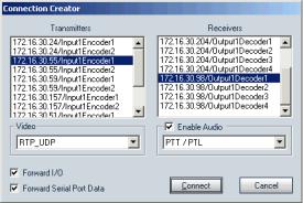
3.Select the Connections tab, then click Add. The Connection Creator window appears.
4.Select a transmitter in the left column and a receiver in the right one.
In the Transmitters column, you have access to the two encoders of each input; the video stream is the same for both. Encoder1 is always reserved for viewing live video with the web interface, therefore you should use Encoder2 for point-to-point connections; however, you can use the same encoder for both functions if you want the same resolution and frame rate.
5.In the Video list, select the desired transmission mode for video data. The available values are:
RTP/UDP—A video mode using RTP (Real Time Transport Protocol, RFC 3550) over UDP. It is the preferred mode for LAN environments; however, it does not guarantee proper reception of packets. (default)
VSIP/UDP—A legacy mode, using the proprietary VSIP video protocol over UDP. The preferred UDP mode is RTP/UDP.
RTP/TCP—A video mode using RTP (Real Time Transport Protocol, RFC 3550) over TCP. It can be useful over WANs, Internet, or LANs needing more robust or secure connections. This mode guarantees proper reception of packets, but could slow down the effective frame rate to a level which is not acceptable.
VSIP/TCP—A legacy mode, using the proprietary VSIP video protocol over TCP. The preferred TCP mode is RTP/TCP.
6.If you are not transferring I/O data (typically alarms) between the two selected devices, clear Forward I/O.
7.If you are not transferring serial port data (like PTZ commands), clear Forward Serial Port Data.
Verint Video Intelligence Solutions |
16 |

2: Configuring and Installing the Device
8.To enable audio between the devices, ensure that Enable Audio is checked, then select the audio mode. The available modes are:
Full Duplex—Audio data is transferred in both directions simultaneously.
PTT/PTL—Push-to-talk/push-to-listen is a half-duplex mode that allows you to control audio communication by using a button to switch from voice reception to transmission mode. Audio data will be transmitted only if the PTT or PTL buttons are pressed.
Note: On a receiver, you can activate audio on a single connection only. The active audio connection is the last that was performed.
The audio connection will remain the same even if the S1970e-R is in guard tour mode, that is, the receiver will not switch between the audio streams of its four connected transmitters. For more information, see page 39.
9.Click Connect.
10.In the SConfigurator confirmation window, click OK.
You should now have video on the analog monitor connected to the receiver. Audio, I/O, and serial port data can also be transferred.
c
Configuring the I/Os
The7 input/output features on the multipin connector on the back of the device are used for alarms (or events) and audio control. The device includes one input contact and one output relay. Their dedicated purpose is:
Input contact —Either transparent alarm link with the output relay or PTT (push-to-talk) audio transmission mode
Output relay—Relay for the input signal of the remote device
You can program PTT and an alarm on the first input at the same time. The relay of the remote device will be closed and PTT will be activated.
Since the S1900e devices are mostly used with a video management software, you will perform most configuration and activation steps within it. Otherwise, in a point-to-point context, use SConfigurator for setup.
17 |
Verint Video Intelligence Solutions |
Nextiva S1900e Series User Guide
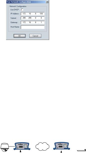
Alarms
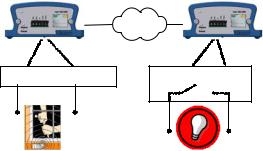
The S1900e devices can generate and receive alarms. In a typical configuration, you plug an event sensor to the input and ground I/O pins on a transmitter, and your alarm system to the two output relay pins of a receiver. For example:
-T |
-R |
Ground Input |
Relay Relay |
With SConfigurator, you activate the alarm process by checking the Forward I/O box in the Connection Creator window.
Audio
The audio connectors are the 3.5 mm jacks on the back of the device; Appendix C on page 71 presents the jack pinouts.
To activate audio between a transmitter and a receiver, both devices must support audio.
Data Transmission
Two transmission modes for audio data are available:
Full duplex—Data is transferred in both directions simultaneously.
PTT—The push-to-talk mode allows you to control audio communication between two devices by pushing a button to transmit.
When creating a point-to-point connection between a receiver and a transmitter in SConfigurator, you set the transmission mode in the Connection Creator window.
To activate the audio transmission channel for PTT on the S1900e device, you must trigger an activation switch (for example, a button) that is based on the shorting of the ground and input pins.
Verint Video Intelligence Solutions |
18 |
2: Configuring and Installing the Device
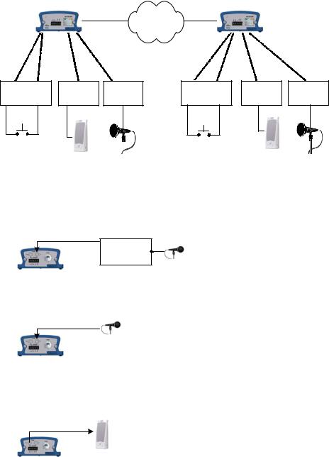
Here is a typical PTT application in a point-to-point context:
-T |
-R |
Gnd |
In |
Audio out Audio in |
Gnd In |
Audio out Audio in |
PTT |
PTT |
|
|
Audio Input/Output Types
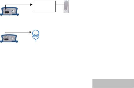
The device supports the following audio input types:
Line-in—To use a 3.5 mm jack (default). In this mode, you need a pre-amplifier. You connect the audio input on the device to the Line-out connector on the pre-amplifier.
Audio In
Line-out
Pre-amp.
Mic (with pre-amp)—To use a multimedia microphone (Electret). Most multimedia microphones use a 3.5 mm jack. You connect the microphone directly in the audio input of the device.
Audio In
With SConfigurator, you set the input type in the Audio > Encoder pane. The device supports the following audio output types:
Speaker—You plug a speaker directly on the audio output of the device.
Audio Out
19 |
Verint Video Intelligence Solutions |
Nextiva S1900e Series User Guide
Line-out with an amplifier and a speaker.
Audio Out |
Line-in |
Amp.
Line-out with headphones, without the need of an amplifier.
Audio Out
In the Audio > Decoder pane of the SConfigurator tool, you can set one output setting, the output gain (volume).
Specifications
The audio input/output specifications are (where 0 dBV = 1 Vrms):
Mode |
Gain |
Impedance |
Frequency Range |
|
|
|
|
|
|
Mic |
-38 to -21 dBV |
30 kohm |
|
|
|
|
|
|
|
Line-in |
-20 to -3 dBV |
30 kohm |
300–3600 Hz |
|
|
|
|
||
Speaker |
-45 to -3 dBV |
8 ohms minimum |
||
|
||||
|
|
|
|
|
Line-out |
-45 to -3 dBV |
16 ohms minimum |
|
|
|
|
|
|
The audio resolution is 16 bits per sample before the compression. The sampling rate is 8 KHz.
The resulting bit rate varies depending on the compression mode:
Compression Mode |
Resulting Bit Rate |
|
|
PCM (no compression) |
128 kbits/s |
|
|
uLaw |
64 kbits/s |
|
|
GSM |
13 kbits/s |
|
|
Verint Video Intelligence Solutions |
20 |

Using the Web Interface
In addition to SConfigurator, another tool is available to interact with the device: the web interface. The web interface allows you to:
View a quick status of the device
Configure the device
View live video and control a PTZ camera
Perform maintenance operations
The web interface is only available with Microsoft Internet Explorer 6.0 or later. You may have to install or upgrade ActiveX controls when accessing the web interface for the first time or after updating your device from a previous firmware release.
Depending on user account and security settings, you may have to provide a user name and password when logging into the web interface or accessing it in secure mode. For more information, see the Security parameters on page 29.
Verint Video Intelligence Solutions |
21 |

Nextiva S1900e Series User Guide
Installing or Upgrading ActiveX Controls
The first time you access the web interface or after updating your device from a previous firmware release, you need to install or upgrade the ActiveX controls for live viewing and firmware update.
To install or upgrade the ActiveX controls:
1.Open a Microsoft Internet Explorer window.
2.Select Tools > Pop-up Blocker > Turn Off Pop-up Blocker.
3.If you upgraded the firmware of the device:
a.Select Tools > Internet Options.
b.In the Temporary Internet files box of the General tab, click Delete Files.
c.In the Delete Files window, check Delete all offline content, then click OK.
d.In the C:\Windows\Downloaded Program Files folder on your computer, delete the
SnPlayer Control and FwuEngineAx Class files.
4.In the Address box, enter the IP address of the device using the http://IP_address format.
Navigation pane
5.Select Tools > Internet Options > Security to lower the security level in your web browser to enable the ActiveX components to install. Select Trusted sites, then click Sites to add the IP address of the device in the trusted sites list.
Verint Video Intelligence Solutions |
22 |
Loading...