

Page 1

®
WANsuite
6450
Reference Manual
March 2004
34-00326.G
i
Page 2

Emissions Requirements
The WANsuite 6450 has been tested and found to comply with the limits for a Class A digital
device, pursuant to EN 55022 and Part 15 of the FCC Rules. These limits are designed to
provide reasonable protection against harmful interference when the equipment is operated in a
commercial environment. This equipment generates, uses, and can radiate radio frequency
energy and if not installed and used in accordance with the instruction manual, may cause
harmful interference to radio communications. This device must also accept any interference
received, including interference that may cause undesired operation.
NOTICE: This WANsuite 6450 was tested and found compliant with EN 55022 using the
modular cable (9-1544-619-009) and ferrite core (21-00111) placed on the cable
end nearest the unit. Both of these items are shipped with the WANsuite 6450.
Release the plastic latch on the outside of the core assembly, place around the
cable, and close.
.WARNING: To reduce the risk of electrical shock, do not remove the cover. There are no
user-serviceable parts inside. Refer servicing to qualified personnel.
This unit contains a lithium battery that is not intended to be field-replaceable.
There is risk of explosion if the wrong battery is installed or if the battery is
installe d inco rrectly.
WARNING: Changes or modifications to this unit not expressly approved by the party
responsible for compliance could void the user’s authority to operate the
equipment.
Canadian Emissions Requirements
This digital apparatus does not exceed the Class A limits for radio noise emissions from digital
apparatus set out in the Radio Interference Regulations of the Canadian Department of Communications.
Le présent appareil numérique n’émet pas de bruits radioélectriques dépassant les limites applicables aux appareils numériques (de la class A) prescrites dans le Règlement sur le brouillage
radioélectrique edicté par le ministère de s Communicati ons du Canada.
FCC Requirements This equipment has been tested and found to comply with Part 68 of the FCC Rules and the
requirements adopted by the ACTA. On the bottom of this equipment is a label that contains,
among other information, a product identifier in the format US: GICDLNAN6450. If requested,
provide this number to the telephone company.
WARNING: Changes or modifications to this unit not expressly approved by the party
responsible for compliance could void the user’s authority to operate the
equipment.
1 All direct connections to the network lines must be made using standard plugs and jacks that
must comply with the applicable FCC Part 68 rules and requirements adopted by the ACTA.
A compliant telephone cord and modular plug are provided with this product. It is designed to
be connected to a compatible modular jack that is also compliant. The table below presents a
list of a pplicab le reg istra tion jac k USO Cs, faci lity interf ace co des (FIC s), and servi ce orde r
codes (SOCs). These are required when ordering service from the telephone company.
Port ID REN/SOC FIC USOC
1.544 Mbps SF
1.544 Mbps SF, B8ZS
1.544 Mbps ANSI ESF
1.544 Mbps ANSI ESF, B8ZS
6.0F 04DU9-BN
04DU9-DN
04DU9-1KN
04DU9 -1SN
RJ11C jack
ii WANsuite 6450
2 If this WANsuite product causes harm to the telephone network, the telephone company will
notify you in advance that temporary discontinuance of service may be required. However, if
Page 3

advance notice is not practical, the telephone company will notify you as soon as possible.
Also, you will be advised of your right to file a complaint with the FCC.
3 The telephone company may make changes in its facilities, equipment, operations, or
procedures that could affect the operation of the equipment. If this happens, the telephone
company will provide advance notice so you can make the modifications necessary to
mainta in unint errup ted servi ce.
4 Parties responsible for equipment requiring AC power should consider including an advisory
notice in their customer information suggesting the customer use a surge arrestor. Telephone
companies report that electrical surges, typically lightning transients, are very destructive to
customer terminal equipment connected to AC power sources. This has been identified as a
major nationwide problem.
Canadian Emissions Requirements
This digital apparatus does not exceed the Class A limits for radio noise emissions from digital
apparatus set out in the Radio Interference Regulations of the Canadian Department of Communications.
Le présent appareil numérique n’émet pas de bruits radioélectriques dépassant les limites applicables aux appareils numériques (de la class A) prescrites dans le Règlement sur le brouillage
radioélectrique edicté par le ministère de s Communicati ons du Canada.
Safety P recauti ons When handling this equipment, follow these basic safety precautions to reduce the risk of elec-
tric shock and injury:
• Follow all warnings and instructions marked on the product and in the manual.
• Unplug the hardware from the wall outlet before cleaning. Do not use liquid cleaners or aerosol cleaners. Use a slightly damp cloth for cleaning.
• Do not place this product on an unstable cart, stand, or table. It may fall, causing seri ous damage to
the product.
• Slots in the unit are provided for ventilation to protect it from overheating. These openings must not
be blocked or covered. Never place this product near a radiator or heat register.
• This product should be operated only from the type of power source indicated on the marking label
and manual. If you are unsure of the type of power supply you are using, consult your dealer or local
power company.
• Do not allow anything to rest on the power cord. Do not locate this product where the cord interferes
with the free movement of people.
• Do not overload wall outlets and extension cords, as this can result in fire or electric shock.
• Never push objects of any kind into the unit. They may touch dangerous voltage points or short out
parts that could result in fire or electric shock. Never spill liquid of any kind on this equipment.
• Unplug the equipment from the wall outlet and refer servicing to qualified service personnel under the
following conditions:
• When the power supply cord or plug is damaged or frayed.
• If liquid has been spilled into the product.
• If the product has been exposed to rain or water.
• If the product has been dropped or if the housing has been damaged.
Safety Certifications IEC 60950 CB Scheme: The WANsuite 6450 from Verilink was tested to the International
Electrotechnical Commission (IEC) CB Scheme (IEC 60950) which is recognized by more than
30 participating countries. This allows Verilink customers around the world to feel confident
that Verilink pro ducts compl y w ith their relevant in ternational standards.
iii
Page 4

iv WANsuite 6450
Page 5

Table of Contents
Preface
About th i s Ma n u al ....... .. ... ......... .. ......... ......... .. ......... .. ......... ... ......... ......... .. ......... .. ......... .. . ................... xi
Manual Organization ...................................................................................................................... xi
Typographic Conventions ..............................................................................................................xi
Customer Service and Technica l Support ........... ............................ .................... .................... ............. xii
Support from Your DSL Service Provider ................... .................... ..................................... ........ xii
Support from Verilink ........ .................... .................... ........... .................... .................................... xii
Telephone ............................................................................................................................... xii
E-mail ..................................................................................................................................... xii
Intern et ..... ......... ......... ....... ......... ......... ......... ......... ....... ......... ......... ......... ....... ......... ............... xiii
Returning a Unit to Verilink ............................................................................................................... xiii
Chapter 1 About the WANsuite 6450
Introduction ......................................................................................................................................... 1-1
Features of the WANsuite 6450 .............. .................... ..................................... .................... .............. 1-3
Performance ................................................................................................................................. 1-3
SNMP Management ................ ......... .. ......... ... ......... .. ......... .. ......... ......... .. ......... ... ......... .. ....... ...... 1-3
Intelligent WAN Access Architecture ......................................................................................... 1-3
Overv i ew an d Ad v an t a g e s ......... .. .. ......... .. ......... ... ......... ......... .. ......... .. ......... .. ......... ... ......... ............... 1-3
Features Summary .............................................................................................................................. 1-4
Front Panel .......................................................................................................................................... 1-6
Rear Panel Connections ...................................................................................................................... 1-7
Power Port .................................................................................................................................... 1-7
Power Failure ......................................................................................................................... 1-7
Supervisory Port ........................................................................................................................... 1-8
10/100 Ethernet Port ..................... ........... .................... .................... ............................................ 1-8
Ethernet LED Indicators ........................................................................................................1-8
Serial Port ..................................................................................................................................... 1-8
CBR Por t ............. .. ......... .. ......... ... ......... ......... .. ......... .. ......... .. ......... ... ......... ......... .. ...................... 1-9
Network Port ................................................................................................................................ 1-9
Chapter 2 Installation
Unpacking and Inspection .................................................................................................................. 2-1
Supplied Materials ........ ........... ..................................... .................... .................... .............................. 2-1
Installation Wizard .............................................................................................................................. 2-2
v
Page 6

Chapter 3 Web Server Interface
Web Server Access ........ ......... ... ......... .. ......... .. ......... .. ......... ......... ... ......... .. ......... .. ......... .................... 3-2
Layout of Interface Screens ......................................................................................................... 3-2
Unit Screen ......... .. ......... ... ......... .. ......... .. ......... ......... .. ......... ... ......... .. ......... .. ......... ....... ...................... 3-2
Mainte n a n c e Reset .. ... .. .. ......... ......... .. ......... ... ......... .. ......... ......... .. ......... .. ......... ... ......... .. ............. 3-4
Save and Restart ........................................................................................................................... 3-5
Interfaces ........... ......... .. ......... .. ......... ... ......... .. ......... ......... .. ......... .. ......... ... ......... ........ ......................... 3-6
Netwo rk .... .... ....... ....... ...... ....... ..... ...... ....... ....... .... ....... ....... ....... ...... ..... ....... ...... ....... .................... 3-6
Configuration Profile Table Screen ....................................................................................... 3-7
Alarm Profile Table Screen ................................................................................................... 3-9
Span E n d poi n t s Screen ... .. ......... ......... .. ......... ... ......... .. ......... ......... .. ......... .. ......... ... ......... ....3-11
CBR ... ....... ......... ......... ......... ......... ...... ......... ......... ......... ....... ......... ......... ......... ......... .................. 3-14
Error Status and Alarm Thresholds Table ........................................................................... 3-16
Serial .......................................................................................................................................... 3-19
DTR Alarm Control and Status Table ................................................................................. 3-23
10/100 Ethernet (IP Servic e Details) ............................ .................... ..................................... .....3-23
Supervisory ................................................................................................................................ 3-26
Servic es .. ...... ....... ....... ....... .... ....... ....... ...... ..... ....... ...... ....... ....... .... ....... ....... ....... .... ........................... 3-27
Service Details Screen ............................................................................................................... 3-27
Interface Deta i l s But t o n ............. .. ......... ......... ... ......... .. ......... .. ......... .. ......... ......... ... ......... .. . .3-28
Type Details Button ............................................................................................................. 3-28
IP Serv i ce Detail s Sc r een ...... .. ......... .. ......... ... ......... .. ......... .. ......... ......... .. ......... ... ......... .. ........... 3-28
Frame Relay Service Details Screen .......................................................................................... 3-28
Status and Alarms T ab l e . .. .. ... ......... ......... .. ......... .. ......... .. ......... ......... ... ......... .. ......... .. ......... 3-32
Frame Relay Port Statistics Screen ...................................................................................... 3-33
DLCI Table Screen ..............................................................................................................3-34
DLCI Details Screen ............................................................................................................3-35
ATM Se rv i c e D e t ai l s Sc r een ... ......... .. ......... ... ......... .. ......... ......... .. ......... .. ......... ... ......... ......... ....3-39
ATM Sta t i s tic s Screen ........ ... ......... ......... .. ......... .. ......... .. ......... ... ......... ......... .. ......... .. ......... 3-41
ATM Vi rt u a l Cha n n e l s Sc r een ....... ......... ......... .. ......... .. ......... .. ......... ......... ... ......... .. ......... .. 3-43
Qualit y of Se rv i ce (Q o S ) Tab l e Screen ..... .. ......... .. ......... ... ......... ......... .. ......... .. ......... .. ....... 3 - 4 8
CES Service Details Screen ....................................................................................................... 3-53
Status ................................................................................................................................... 3-57
Channel Tabl e D et a i ls S creen .... ......... ......... .. ......... ... ......... .. ......... ......... .. ......... .. ......... ... .... 3- 5 9
Serial CES Configuration .................................................................................................... 3-61
Valid Channel Ranges for Serial and CBR Interfaces ......................................................... 3-61
HDLC/ PPP Serv i ce ............. .. ......... ......... .. ......... .. ......... ... ......... ......... .. ......... .. ......... .. ......... . ...... 3-62
Applic ations ........ ......... ....... ......... ......... ......... ......... ....... ......... ......... ......... ...... ......... ......................... 3-62
Service Aware ............................................................................................................................ 3-62
Rule De t ai l s Screen ...... .. ......... ......... .. ......... .. ......... ... ......... ......... .. ......... .. ......... .. ......... ... .... 3-63
Traffic Meter Statistics Screen ............................................................................................ 3-65
SNMP .. ........... ......... ............ ........... ........... ........... ......... ............ ........... ........... ........... ................ 3-66
Trap L og ... .. ......... .. ......... ......... .. ......... ... ......... .. ......... .. ......... ......... .. ......... ... ......... .. .................... 3-67
Top Talkers ................................................................................................................................ 3-67
IP Gatew ay ........ ......... .. ......... .. ......... .. ......... ......... ... ......... .. ......... .. ......... ......... .. ......... ................ 3-69
RIP Parameters .................................................................................................................... 3-70
OSPF Pa r a m e t ers ....... ... ......... .. ......... ......... .. ......... .. ......... ... ......... .. ......... ......... .. ......... .. ....... 3-70
Circuit Table Screen ............................................................................................................3-70
vi WANsuite 6450
Page 7

Static Route Table Screen .................................................................................................... 3-73
Static ARP Table Screen ..................................................................................................... 3-76
Trusted Neighbor Table Scre en ......................... ........... .................... .................... ...............3-77
Area Table Screen ...............................................................................................................3-78
Virtua l L i nk T ab l e S creen ......... .. ......... ... ......... .. ......... .. ......... .. ......... ......... ... ......... .. ......... .. 3-80
Originate Ping ............................................................................................................................ 3-82
Netwo r k Add r e s s T ra n s l at i on (N A T ) ........ ......... .. ......... ... ......... .. ......... .. ......... ......... .. ......... ... .... 3- 8 3
NAT Details Screen .............................................................................................................3-83
Static TC P T r an s l at i o n T ab l e Screen .. .. ... ......... .. ......... .. ......... .. ......... ......... ... ......... .. ......... .. 3-85
Static UDP Translation Table Screen .................................................................................. 3-86
NAT Port Table Screen ....................................................................................................... 3-87
Dynamic Host Configuration Protocol (DHCP) ........................................................................ 3-89
DHCP Server Details Screen ...............................................................................................3-89
DHCP Host Table Screen .................................................................................................... 3-90
Static Entry Table Screen .................................................................................................... 3-91
IP Address List Table Screen .............................................................................................. 3-92
IP Add res s S t at us T ab l e S creen ........ .. ......... ......... .. ......... ... ......... .. ......... ......... .. ......... .. ....... 3 - 9 3
Bridge ........... ........... ............ ......... ........... ........... ........... ............ ......... ........... ........... .................. 3-93
Simple Mail Transfer Protocol (SMTP) ..................................................................................... 3-97
Utilities ............................................................................................................................................. 3-98
Upload/Save ............................................................................................................................... 3-98
TFTP Configuration ............................................................................................................ 3-98
Password ....................................................................................................................................3-99
Log Out .................................................................................................................................... 3-100
Chapter 4 VT100 Interface
Introduction ......................................................................................................................................... 4-1
Screen Co mpone n ts ...... .. ......... ......... .. ......... ... ......... .. ......... ......... .. ......... .. ......... ... ......... .. ............. 4-1
Curso r Co n t r o l s ..... ......... .. ......... ......... ... ......... .. ......... .. ......... ......... .. ......... ... ......... .. ...................... 4-1
Field Types ...................................................................................................................................4-2
Menu Structure ............................................................................................................................. 4-3
System Screen ..................................................................................................................................... 4-4
Mainte n a n c e Reset .. ... .. .. ......... ......... .. ......... ... ......... .. ......... ......... .. ......... .. ......... ... ......... .. ............. 4-5
Mainte n a n c e Reset .. ... .. .. ......... ......... .. ......... ... ......... .. ......... ......... .. ......... .. ......... ... ......... .. ............. 4-5
Save and Restart ........................................................................................................................... 4-6
Interfaces ........... ......... .. ......... .. ......... ... ......... .. ......... ......... .. ......... .. ......... ... ......... ........ ......................... 4-7
Netwo rk .... .... ....... ....... ...... ....... ..... ...... ....... ....... .... ....... ....... ....... ...... ..... ....... ...... ....... .................... 4-7
Configuration Profiles Screen ...............................................................................................4-9
Alarm Profiles Screen ..........................................................................................................4-11
Span E n d poi n t s Screen ... .. ......... ......... .. ......... ... ......... .. ......... ......... .. ......... .. ......... ... ......... ....4-13
CBR ... ....... ......... ......... ......... ......... ...... ......... ......... ......... ....... ......... ......... ......... ......... .................. 4-17
Error Status and Alarm Thresholds Table ........................................................................... 4-18
Performance Screens ........................................................................................................... 4-20
Serial .......................................................................................................................................... 4-22
10/100 Ethernet (IP Detai ls) .............................. .................... .................... .................................4-26
Supervisory ................................................................................................................................ 4-28
Servic es .. ...... ....... ....... ....... .... ....... ....... ...... ..... ....... ...... ....... ....... .... ....... ....... ....... .... ........................... 4-29
vii
Page 8

Addin g a Se rv i ce ....... ... .. ......... .. ......... .. ......... ... ......... ......... .. ......... .. ......... .. ......... ......... ... . ... 4-29
Servic e D et a ils Sc r e en ......... .. ......... .. ......... .. ......... ......... ... ......... .. ......... .. ......... .. ......... ........ ........ 4-29
IP Serv i ce Detail s Sc r een ...... .. ......... .. ......... ... ......... .. ......... .. ......... ......... .. ......... ... ......... .. ........... 4-30
Frame Relay Service Details Screen .......................................................................................... 4-30
Frame Relay Statistics Screen ............................................................................................. 4-34
DLCI Table Screen ..............................................................................................................4-36
DLCI Details Screen ............................................................................................................4-37
ATM Se rv i c e D e t ai l s Sc r een ... ......... .. ......... ... ......... .. ......... ......... .. ......... .. ......... ... ......... ......... ....4-41
ATM Sta t i s tic s Screen ........ ... ......... ......... .. ......... .. ......... .. ......... ... ......... ......... .. ......... .. ......... 4-43
ATM Virtual Channel Table Screen .................................................................................... 4-44
Quality of Service (QoS) Profile Screen .............................................................................4-48
CES Service Details Screen ....................................................................................................... 4-54
Status ................................................................................................................................... 4-57
Channel Tabl e D et a i ls S creen .... ......... ......... .. ......... ... ......... .. ......... ......... .. ......... .. ......... ... .... 4- 5 8
Serial CES Configuration .................................................................................................... 4-61
Valid Channel Ranges for Serial and CBR Interfaces ......................................................... 4-61
HDLC/ PPP Serv i ce ............. .. ......... ......... .. ......... .. ......... ... ......... ......... .. ......... .. ......... .. ......... . ...... 4-62
Applic ations ........ ......... ....... ......... ......... ......... ......... ....... ......... ......... ......... ...... ......... ......................... 4-62
Service Aware ............................................................................................................................ 4-63
Rule Co n fi g Sc reen .. ......... .. ......... ... ......... ......... .. ......... .. ......... .. ......... ... ......... ......... .. ...........4-64
Traffic Meter Statistics Screen ............................................................................................ 4-65
Trap L og ... .. ......... .. ......... ......... .. ......... ... ......... .. ......... .. ......... ......... .. ......... ... ......... .. .................... 4-66
IP Gatew ay ........ ......... .. ......... .. ......... .. ......... ......... ... ......... .. ......... .. ......... ......... .. ......... ................ 4-66
RIP Parameters .................................................................................................................... 4-67
OSPF Pa r a m e t ers ....... ... ......... .. ......... ......... .. ......... .. ......... ... ......... .. ......... ......... .. ......... .. ....... 4-68
Circuit Table Screen ............................................................................................................4-68
Static Route Table Screen .................................................................................................... 4-71
Static ARP Table Screen ..................................................................................................... 4-73
Trusted Neighbors Screen ............ ..................................... .................... .................... ..........4-75
Area Table Screen ...............................................................................................................4-75
Virtua l L i nk T ab l e S creen ......... .. ......... ... ......... .. ......... .. ......... .. ......... ......... ... ......... .. ......... .. 4-77
Network Address Translation (NAT) ........................................................................................ 4-79
NAT Details Screen .............................................................................................................4-79
Bridge ........... ........... ............ ......... ........... ........... ........... ............ ......... ........... ........... .................. 4-86
TFTP Configuration ................................................................................................................... 4-89
SNMP .. ........... ......... ............ ........... ........... ........... ......... ............ ........... ........... ........... ................ 4-90
Top Talkers ................................................................................................................................ 4-91
Originate Ping ............................................................................................................................ 4-93
Dynamic Host Configuration Protocol (DHCP) ........................................................................ 4-94
DHCP Server Details Screen ...............................................................................................4-94
Simple Mail Transfer Protocol (SMTP) ..................................................................................... 4-98
Appendix A Specifications
Network Interface - SHDSL Port ...................................................................................................... A-1
CBR Int e rface ............ .. ......... .. ......... ... ......... .. ......... ......... .. ......... .. ......... ... ......... ......... .. ..................... A-1
E1 ................................................................................................................................................ A-1
T1 ................................................................................................................................................ A-2
viii WANsuite 6450
Page 9

Serial Interface ................................................................................................................................... A-2
IP Gatew ay ...... .. ......... .. ......... .. ......... ......... ... ......... .. ......... .. ......... ......... .. ......... ... ......... ....................... A-2
10/100 Ethernet (IP Gateway or Manage ment) ....... .................... .................... .................... .......A-2
Management Interfaces ...................................................................................................................... A-2
Embedded Operations Channel ................................................................................................... A-2
10/100 Ethernet ............................................. ........... .................... .................... ........................... A-2
Supervisory Port .......................................................................................................................... A-2
Diagnostics ........................................................................................................................................ A-3
Alarms ................................................................................................................................................ A-3
Power ................................................................................................................................................. A-3
Mecha nic al . ..... .... ..... .. .... ..... .... ... .... ..... .... .. ..... .... ..... .... ... .... ..... .... .. ..... .... ..... .. ..... .... ..... .. ..................... A-3
Enviro n mental . .. ......... .. ......... .. ......... ......... ... ......... .. ......... .. ......... ......... .. ......... ... ......... .. ..................... A-3
Industry Listings ................................................................................................................................ A-3
Standa rds ........ .............. ............. .............. ............. ..................... ............. .................... ................. A-4
Ordering Information .........................................................................................................................A-4
Standard Equipment .................................................................................................................... A-4
Optional Equipment .................................................................................................................... A-5
Connector Pin Assignments ............................................................................................................... A-6
Serial Interface Pin Assignments, DTE Mode (Packet Use Only) .............................................. A-6
Serial Interface Pin Assignments, DCE Mode ........................................................................... A-7
Ethernet Connection Pin Assignments ........................................................................................ A-8
Network Interface Pin Assignments ............................................................................................ A-8
CBR Int e rface Pin Ass i g n m e nt s ... ......... .. ......... .. ......... .. ......... ......... ... ......... .. ......... .. ......... ..........A-8
Supervisory Port Pin Assignments .............................................................................................. A-9
Appendix B SNMP Agent
Introduction .........................................................................................................................................B-1
SNMP Co n f i g u ra ti o n P aramete rs .. .. ......... ... ......... .. ......... .. ......... ......... .. ......... ... ......... .. ......... .. ...........B-1
SNMP MIBs ......... ... .. ......... ......... .. ......... .. ......... ... ......... ......... .. ......... .. ......... .. ......... ... ...... ..................B-1
SNMP T ra p Co n f i g u rat i o n ... .. ... ......... ......... .. ......... .. ......... .. ......... ... ......... ......... .. ......... .. ......... . ..........B-2
Generic MIB Loading Instructions .....................................................................................................B-2
ix
Page 10

x WANsuite 6450
Page 11

About this Manual
This reference guide for the WANsuite 6450 ATM integrated access device
(IAD) describes unit features and specifications, configuration, and cabling. It
is not a users guide containing step-by-step procedures. Rather, this manual is
designed to be used as a reference regarding commands, interface ports,
configuration parameters, and other specific information about the WANsuite
6450.
Manual Organization
The chapters and appendices in this manual are arranged for quick reference
when you need it. You do not have to read previous chapters to understand
the subsequent chapters. Appendices are designed to complement the main
chapters.
• Chapter 1, About the WANsuite 6450 – This chapter describes product
features and capabilities.
• Chapter 2, Installation – This chapter describes unit port connections and
powering informatio n.
C
HAPTER
0
P
REFACE
• Chapter 3, Web Server Interface – This chapter describes the menu screens
and configuration para meters accessed through the Web server interface.
• Appendix A, Specifications − This appendix defines the specifications for the
WANsuite 6450. In addition, thi s section provides ordering information and
all the connector pin assignm ents for the interfaces on the rear panel of the
WANsuite 6450.
• Appendix B, SNMP Agent − This appendix defines which Management
Information Base (MIB) fil es are supported by the WANsuite 6450 SNMP
agent. In addition, instr uctions are provided for loading these MIB files into
most SNMP management stations.
Typog raphic Conv entions
The following table lists the graphic conventions used throughout this guide.
Preface xi
Page 12
Convention Description
A Notice calls attentions to important feature s or in st ructions.
A Caution alerts you to s erious risk of data loss or other
results that may c aus e you or the unit trouble i f the warnin g is
not heeded.
A Warning a lerts you t o the risk of serious damage to the unit
or injury and possible death to the end user.
Customer Service and Technical Support
Verilink provides easy access to customer support through a variety of
services. Thi s section describes thes e services.
Support from Your DSL Service Provider
If assistance is required, contact your service provider. When you contact
your service provider for assistance, have the following information ready:
• Diagnostic error messages
• A list of system hardware and software, including revision le vels
• Details about recent configuration changes, if applicable
Support from Verilink
If you are unable to receive support from your service provider or want to
contact us directly, Verilink offers worldwide customer support by telephone,
e-mail, and through Verilink’s Internet Web site.
Telephone
Customer support is available by telephone 24 hours a day, 7 days a week. To
speak directly with a Verilink customer service representative, you may dial
one of the following numbers:
•Sales and Marketing: 800-VERILINK (837-4546)
•Technical Support: 800-285-2755 (toll-free)
You can request sales and marketing information or pose a technical support
question about your Verilink product by contacting us at the e-mail addresses
provided below. Verilink will respond to e-mailed requests for support during
regular business hours (8–5 CST, Monday–Friday).
1-256-32 7-2255 (int ernational)
xii WANsuite 6450
Page 13

•Sales and Marketing: info@verilink.com
•Technical Support: support@verilink.com
Internet
Visit Verilink’s Web site to access the latest Verilink product information,
technical publications, news releases, contact information, and more:
If this reference manual is revised to reflect code changes or other updates,
the most recent version will be posted to the Verilink Web site.
Returning a Unit to Verilink
If for any reason you must return your Verilink product, it must be returned
with the shipping prepaid, and pac kaged to t he best commer cial stand ard for
electronic equipment. Verilink will pay shipping charges for delivery on
return. You are responsible for mode and cost of shipment to Verilink.
You must have a Return Material Authorization (RMA) number marked on
the shipping package. Products sent to Verilink without RMA numbers will be
returned to the sender unopened, at the sender’s expense.
http://www.verilink.com
A product sent directly to Verilink for repair must first be assigned an RMA
number. You may obtain an RMA number by calling Customer Service at
800-926-0085, extension 3002 (international number: 1-800-256-327-2255).
When calling Verilink for an RMA, please have the following information
available:
• Model number and serial numb er for eac h unit
• Reason for return and symptoms of problem
• Purchase order number to cover charges for out-of-warranty items
• Name and ph one number of per son we ca n conta ct i f we have qu est ions abo ut
the unit(s)
The address for you to use when returning a unit to Verilink will be provided
when the RMA is issued. The standard delivery method for return shipments
is Standard Ground for domestic returns and International Economy for
international returns (unless otherwise specified).
Preface xiii
Page 14

xiv WANsuite 6450
Page 15

Introduction
C HAPTER
1
C
HAPTER
1
A
BOUT THE
Verilink’s WANsuite 6450 is a feature-rich, intelligent integrated access device
(IAD) that manages voice and data applications in an ATM network. The
WANsuite 6450 terminates a standards-based Symmetric High-Bit Rate
Digital Subscriber Line (SHDSL) that originates from a Digital Subscriber
Line Access Multiplexer (DSLAM) and provides interfaces for the end user’s
communications equipment.
WAN
SUITE
6450
The WANsuite 6450 is ServiceAware™ IAD with the following hardware: an
SHDSL network interface; a Constant Bit Rate (CBR) port configurable as T1
or E1; a Serial port software-configurable for V.35, V.36, X.21, RS-232, RS449, or EIA-530; a 10/100Base-T Ethernet port; an asynchronous Supervisory
port; five tri-color status LEDs; and front panel reset and factory
configuration buttons.
The Circuit Emulation Service (CES) support provides for the encapsulation
of TDM traffic from end-user equipment into ATM cells for transport across
the WAN to the DSLAM and on to the ATM network. This allows for the
continued use of existing TDM equipment at the premise while the ATM
network continues to grow and move further out to the edge. This unit
supports CES over the CBR port and the Serial port.
A router or bridge using PPP/HDLC or Frame Relay protocol connects to the
WANsuite 6450’s Serial port. The unit encapsulates the PPP data into ATM
cells using Internet Engineering Task Force (IETF) RFC 1483. Any router/
bridge supporting PPP over ATM (PPPoA) RFC 1483 encapsulation can be
used at the other end of this ATM c onnection.
The IP Gateway feature enables IP packet routing throughout a LAN/WAN
network architecture using static routing configuration or dynamic routing
protocols (Routing Information Protocol − RIP 1 and RIP 2, or Open Shortest
Path Fir st − OSPF), Dynamic Host Communications Protocol − DHCP, and
Network Address Translation − NAT.
RIP 1 and RIP 2 allow routers to exchange routing information. The
WANsuite 6450 then uses this information exchange to build routing tables
About the WANsuite 6450 1-1
Page 16

for IP Packet routes. After building the routing tables, the unit periodically
broadcasts the contents to neighboring routers so your network can choose the
most efficien t routes a vailab le.
OSPF uses link-state routing algorithms to calculate routes based on the
number of routers, transmission speeds, delays, and route costs. Using the
OSPF protocol, the WANsuite 6450 works with other routers in your
telecommunications fabric to dynamically change routes “on the fly” to make
use of the most effici ent and cost-effecti ve transit across your netw ork.
Bridging separate LANs together is another option for the IP traffic. Using the
IEEE Standard 802.1D Transparent Bridging specification, the WANsuite
6450 can simplify your network architecture by allowing you to bridge
separate LANs across a WAN so they operate as a single LAN.
Because IP Gateway enables the WANsuite 6450 to route IP traffic either
statically or dynamically or to bridge IP traffic across your LAN/WAN
architecture, your need for costly routers is substantially reduced. This onestop solution can help you meet the requirements of your many different
applications.
DHCP uses a server-client architecture to assign IP Addresses to PCs and
workstations on the LAN. The DHCP server dynamically assigns these IP
Addresses, which can be either temporary or permanent, to each PC or
workstation (DHCP client). These IP Addresses are "housed" on the DHCP
server. The flexibility to reassign IP Addresses saves the end user money by
eliminating the need for a single IP Address for each piece of equipment on
the LAN.
NAT enables an enterprise to set up two sets of IP Addresses − one s et for
internal network use (or LAN traffic) and one set for external use (or Internet
traffic). This can provide a layer of security for a company by eliminating
outside a ccess to in ternal IP Addres ses from t he Int ernet.
The WANsuite 6450 gives service providers and enterprise customers the
capability to monitor end-to-end network performance (with support of up to
16 virtual channels); isolate performance problems to the LAN, local loop, or
ATM network; determine appropriate bandwidth needs; and monitor network
trends to aid in future capacity planning.
All of the WANsuite 6450’s installation, performance configuration, traffic
monitoring, alarm reporting, and diagnostic capabilities can be configured
through the unit’s embedded Web server interface using Microsoft
®
Internet
Explorer™. The Web server interface can be accessed locally through the
Ethernet port or the Supervisory port, or remotely through the Network port.
Especially advantageous is WANsuite’s advanced monitoring and control
capability that gives network administrators the ability to plan future capacity
requirements.
The unit’s built-in Service Aware technology lets network managers maximize
available WA N bandwidth and verify SLAs. This management platform lets
the end user see network activity (performance) and problems (diagnostics) on
any permanent virtual circuit (PVC), access line, or physical circuit.
1-2 WANsuite 6450
Page 17

Features of the WANsuite 6450
Performance
Historically, WAN access devices have tended to perform well as singlefunction devices such as CSU/DSUs, but have not been optimized to address
higher-level traffic issues such as service levels and integration. Verilink's
architectur e and Web-based us er interfac e work together to address all acce ss
issues such as services and applications, rather than as circuits and protocols,
for except ional WAN managemen t perform ance.
To further leverage its Web browser interface, Verilink's new architecture also
allows firmware to be upgraded via the Web from a standard browser, with
password control, if desired.
SNMP Management
With integrated SNMP in-band management, enterprise managers can now
manage Verilink WANsuite units and their integral CSU/DSUs as a single
unit. With only one LAN segment in the network, the WA Nsuite 6450 can be
managed by SNMP. By downloading all configuration parameters from the
central site, no interaction is required at remote sites to establish connectivity.
The unit allows any port to be configured for any of its available service
technologies through simple software configuration. Network managers can
now fine tune the enterprise network for the lowest cost and highest
performance.
Intelligent WA N Access Architecture
Verilink's next-generation WAN access architecture is built around a
PowerPC™ processor with 50 MIPS of processing power and 16 Mbytes of
onboard memory, and works with non-proprietary network management
solutions via SNMP. An embedded Web server supplies a simple-to-use
interface for configuration and statistics collection, with a service table for
mapping services to ports and a user table for monitoring and controlling
traffic.
Overview and Advantages
Verilink’s WANsuite 6450 is an innovative, highly intelligent, software-based
WAN access device optimized for ATM over SHDSL access. This unit
provides network managers with all the tools necessary to monitor and
troubleshoot voice, data, and network transmission systems. The ability to use
the WANsuite 6450 unit as an IP Gateway greatly increases its flexibility,
while reducing networking costs. In addition, the WANsuite 6450 is a
valuable tool for the following:
• Measuring and reporting performance
About the WANsuite 6450 1-3
Page 18

• Managing network resources to ensure optimum performance
• Analyzing trends to aid in network planning
WANsuite 6450 advantages include the following:
• Enables a new class of xDSL technologies − the internationally standard
SHDSL.
• Allows for continued use of existing TDM equipment by support ing CES via
AAL1.
• Reduces the need for cos tly routers with its IP Gateway feature.
• Offers easy install ation and configu ration, reduc ing maintenanc e and sparing
costs.
• Controls recurring ATM access costs − WANsuite product s quickly pay for
themselves by allowing enterprises and service providers to optimize the use
of valuable bandwidth.
• Allows for use of existing routers without changing the ext ernal router’s
configuration by running PPP over an ATM network.
Features Summary
• Powerful core architecture
• SHDSL network port for symmetrical data rates ranging from 192 kbps to
2.312 Mbps
• T1 or E1 circuit emulation
• 10/100Base-T Etherne t port and asynchronous Supervisory port
• Serial data port , use r-selectable V.35, V.36, RS- 232, or EIA-530
• Intuitive Web browse r for management
• CES
• Constant Bit Rate (CBR) port configurable for T1 or E1 supporting the
following modes:
• Unframed T 1 − 1.544 Mbps raw bit stream
• T1 ESF
• T1 D4
• Unframed E1 (G.703) framing − 2.048 Mbps raw bit stream
• E1 CCS framing
• E1 CAS framing
• AAL1 ATM encapsulation
• Structured Nx64 basic servic e supporting full or partial T1/E1 circuits
1-4 WANsuite 6450
• Structured Nx64 servic e with Channel Associated Signaling (CAS)
supporting the following:
• E1 CAS signaling
• T1 robbed bit signaling
Page 19

• Full or partial T1/E1 circuits with signaling
• Unstructured servi ce (2.048 Mbps E1 or 1.544 Mbps T1)
• Configurable for synchronous or adaptive timing
• User-configurable Cell Delay Variation
• User-configurable partial cell fill
• User-config urable automati c c hannel c onfigur ation for E1 C CS or E1 CAS
services
• User-config urable scrambling /descrambling of ATM cell Payload using an
43
x
+1 polynomial
• User-config urable time slot multiplexing between the CBR port and the
Serial port
• For Nx64 basic and CAS services, the user can individually configure
the CES channels for the CBR port or for the Serial port
• For Unstructured E1 service , the user can co nfigure all channels for
either the CBR port of for the Serial port
• IP Gateway
• 10/100Base-T Ethernet port
• Static routes
• Static Address Resolution Protocol (ARP)
• Dynamic routing proto cols, including RIP 1, RIP 2, and OSPF
• Un-numbered network
• Address Management: NAT and DHCP
• Bridging
• Programmable alarm thresholds
• IPoA
• Serial Port Configurab le for PPP, Frame Relay, or CES
• Supports V.35, V.36, EIA-530, or RS-232
• PPPoA
• Management Interf aces
• An innovative Web-based use r interface
• Embedded HTTP server for remote configu ration and real-time
reporting via Web browser
• Decreased installa tion and configuration time for ser vice employees
• Simplified trouble shooting and fault isolation of network problems
• Optimal management of ATM-based servic es
• Saves and downloads configur ati on files from remote server
• EOC for SHDS L-rel at e d para meters
• SNMP
• VT100
About the WANsuite 6450 1-5
Page 20

Front Panel
• Frame Relay-to -ATM Networ k/ Ser v ic e Interworkin g
• Supports FRF.8 Frame/ATM ser vice interworking and maps Frame
datalink connecti on identif ier s (DLCIs) to ATM per manent vir tual cir cuits
(PVCs); up to 20 VCs can be configured.
• Provides network interworking functionality that allows Frame Relay end
users to communicate over an inte rmedi ate ATM network that supports
FRF.5.
• Benefits I nternet ser vice pr ovid ers tha t need to link Frame R elay a nd ATM
networks, especially those networks with ATM backbones and Frame
Relay end users.
The front panel of the WANsuite 6450 is shown below in Figure 1.1.
Figure 1.1
Front Panel of WANsu ite 6450
The front panel’s five LED status indicators are described below:
Indicator Description
MODE
CBR
NET
ALARM
POWER
Normally, this indicator lights green.
The indi cator lig ht s amber while configuratio n is being set by th e front panel
buttons or when the configuration is changed by SNMP or through the Web
inter fa ce . T he ind i cator wil l remain ambe r un til the cha n ge d con f ig ur ation is
saved; it will revert to green when the new configuration has been saved.
The indicator i s off (not illuminated) when the CBR port has not been
configured.
The indi cator lig ht s green when the CBR port link is up and is receiving AAL1
cells.
The indi cator lig ht s red when the CBR port has been configured and no AAL1
cells ar e receiv ed.
The indicator lights amber when the CBR port link is up but AAL 1 cel ls are not
being rec eived.
The indicator is off (not illuminated) when the Network port has not been
configured.
The indi cator lig ht s green when the Network port link is up and the ATM
protocol is establi shed.
The indi cator lig ht s red when the Network po rt link is down and the ATM
protocol is not establi shed.
The indi cator lig ht s amber when the Network port link is up, but the ATM
protocol is not establi shed.
The indi cator lig ht s red if an alarm condition exists.
The indi cator lig ht s amber if a “yellow ” alarm condition exists.
The indi cator lig ht s green when power is applied to the unit.
The indi cator lig ht s amber when the unit is in a test mode loop back.
1-6 WANsuite 6450
Page 21

The user-activated input control buttons are described below:
Button Description
RESET
CONFIG
*The CONFIG button must be held until the MODE LED lights amber and remains illuminated for the
default config ur at io n to take ef fect.
Provid es a hardware reset to the u nit.
Sets the unit back to its factory defa ult Ethernet or HDLC configuration; this is
the same as a maintenance reset.
To initia te this functio n, you must pre ss an d hold the
power-up sequence.*
Rear Panel Connections
The rear panel of the WANsuite 6450 has five connectors. From left to right,
these are a s follows :
SERIAL
Figure 1.2
Power Port
, CBR, and NETWORK as shown in Figure 1.2 below.
WANsuite 6450 Rear Panel
CONFIG button during a
POWER, SUPERVISORY PORT, 10/100 ETHERNE T,
The POWER port on the WANsuite 6450 unit is a standard, grounded, threeprong connector. This 110/220 VAC power receptacle is rated at 50–60 Hz,
0.2 A/0.1 A. To apply power to the unit, simply plug the supplied power cord
into the unit’s
POWER port and then connect the wall plug to an appropriate
electrical outlet. The unit has no power switch.
When power is applied to any WANsuite 6450 unit, the front panel indicators
flash for approximately 10 to 15 seconds as the unit initializes. The green
POWER LED on the front panel will remain illuminated as long as the unit
receives power. This LED turns amber when the unit is in test mode.
CAUTION: Always connect the power cord to a grounded electrical outlet.
NOTICE: Per UL 1950 and CSA 60950 Clause 1.7.2, if the power supply cord is
intended to serve as a disconnect device, an easily accessible socket
must be installed near the equipment.
Power Failure
If the indicator does not illuminate, check the power connections and the
primary circuit breaker.
About the WANsuite 6450 1-7
Page 22

Supervisory Port
The WANsuite 6450 units provide nonvolatile memory retention of the unit
configuration in case of a power failure. The unit will automatically restore
normal service following a power loss and will retain pre-existing time and
date information.
The SUPERVISORY port is a DB-9 female D CE c onnector co nfigure d for 8
bits, no parity, and 1 stop bit. Bit rates are configured through the Web server
interface. (S ee Unit Access Details on page 3-26.) The Supervisory port speed
can be set to 1200, 2400, 4800, 9600, 19200, 38400, 57600, or 115200 bps.
The initial default rate of the Supervisory port is 19200 bps.
On power-up, the Supervisory port sends out diagnostic messages at the bit
rate of 115.2 kbps until the Supervisory service acquires the Supervisory port,
after which the port speed is changed to the setting in the Supervisory
interface s creen.
NOTICE: For information on pinout assignments for this connector, refer to
Supervisory Port Pin Assignments on page A-9. See Standard
Equipment on page A-4 for information on cables for this connector.
10/100 Ethernet Port
The WANsuit e 64 50 pr ovi des a singl e 10/100 ETHERNET interf ace port for IP
Gateway, SNMP, and Web browser access. This interface is an eight-pin
modular jack that complies with standard twisted-pair, 10/100Base-T
requirements. The 10/100Base-T cable is supplied by the end user. Refer to
Ethernet Connection Pin Assignments on page A-8 for pin assignments and
cable descriptions.
Ethernet LED Indicator s
There are two unlabeled indicator LEDs on either side of the 10/100 Ethernet
jack. The LED on the left side of the jack pulses amber to indicate data
activity (either transmit or receive). The LED on the right side of the jack
lights green to indicate that the link layer is operational.
Serial Port
The SERIAL interface port located on the WANsuite 6450 rear panel is a
multi-protocol interface presented physically as a DB-25 connection. The
protocols supported by this interface are RS-232, V.35, V.36, EIA-530, X.21,
and RS-449.
1-8 WANsuite 6450
Cables that adap t the DB-25 interface to the 34-pin V.35 interfa ce are
available. DB-25 to DB-25 cables are also available if your installation needs
require them. See Standard Equipment on page A-4 for details. Pin
assignmen ts for the Serial interface a re listed in Serial Interface Pin
Page 23

CBR Port
Assignments, DTE Mode (Packet Use Only) on page A-6 and Serial Interface
Pin Assignments, DCE Mode on page A-7.
CAUTION: FCC rules require that interconnecting cables carrying high-speed
data be shielded appropriately to minimize radio frequency
interference.
CAUTION: The T1/E1 CBR port is not a standalone port. Connect the T1/E1 CBR
port only to the "private" side of the network on the customer
premises, never to the "public" side.
The CBR interface port located on the WANsuite 6450 rear panel is an
RJ11C, eight - pin modular jack that can be software-selectable for T1 or E1.
As a T1 port, it terminates as 100 ohms, and as an E1 port at 120 ohms. This
port is used to transport TDM traffic using a T1/E1 framer to provide ATM
adaptation Layer 1 with Circuit Emulation Services (AAL1-CES).
To view the pinout assignments for this interface, refer to CBR Interface Pin
Assignments on page A-8.
Network Port
The WANsuite 6450 has one rear panel NETWORK interface port. This
connection is a standard RJ11C, eight-pin modular jack that terminates as 135
ohms.
To view the pinout assignments for this interface, refer to Network Interface
Pin Assignments on page A-8.
About the WANsuite 6450 1-9
Page 24

1-10 WANsuite 6450
Page 25

This chapter describes the contents of your WANsuite 6450 shipment and
provides information on connecting and installing the unit.
The WANsuite 6450 uses an “Installation Wizard” to help you automatically
install the unit quickly and correctly. Procedures for using this Installation
Wizard are also describe d in this c hapter.
Unpacking and Inspection
C HAPTER
2
C
HAPTER
2
I
NSTALLATION
The WANsuite 6450 is shipped in cardboard cartons with foam inserts for
shock and vibration protection. When your shipment arrives, inspect the
shipping container and contents, and compare all items with those on the
packing list.
If the contents of the shipment are incomplete or if there is mechanical
damage or defect, notify Verilink. (Refer to Support from Verilink on
page xii.) If the shipping container or cushioning material is damaged, notify
the carrier and Verilink immediately and make a notation on the delivery
receipt that the container was damaged. (If possible, obtain the signature and
name of the person making delivery.) Retain the packaging material until the
contents of the shipment have been checked for completeness and the unit has
been check ed both m echan ically and electrical ly.
Supplied Materials
The WANsuite 6450 ships with the following standard items:
• Serial (Super visory) cable
• Network cable
• Power cord
• Verilink Documentation CD
Installation 2-1
Page 26
For specific applications, see Connector Pin Assignments on page A-6 for
additional optional cables and adapters. Contact Verilink Technical Support
(page xii) for furthe r assist ance.
Installation Wizard
The WANsuite 6450 can be configured and monitored through the Web server
interface. To gain access to this interface, the unit must be configured with an
IP Address. Verilink provides a DOS-based program – the Verilink
Configuration Wizard – to aid in this initial configuration.
NOTICE: You may also access the Verilink Configuration Wizard on the
To configure the IP Address using the Ve rilink Configuration Wizard, perform
the following steps:
1 Using the supplied cable, connect the unit’s DB-9 Supervisory port to a
COM port on your PC. (Take note of which COM port is connected.)
2 Insert the Verilink CD (provided with the WANsuite 6450) into your PC’s
CD-ROM drive.
Verilink We b site: www. verilink.com.
3 Use Windows “Explore” to view the contents of the CD and select the
folder labeled “Utilities.” In this folder will be a file named
this executable fil e is the Verilink Configuration Wizard application.
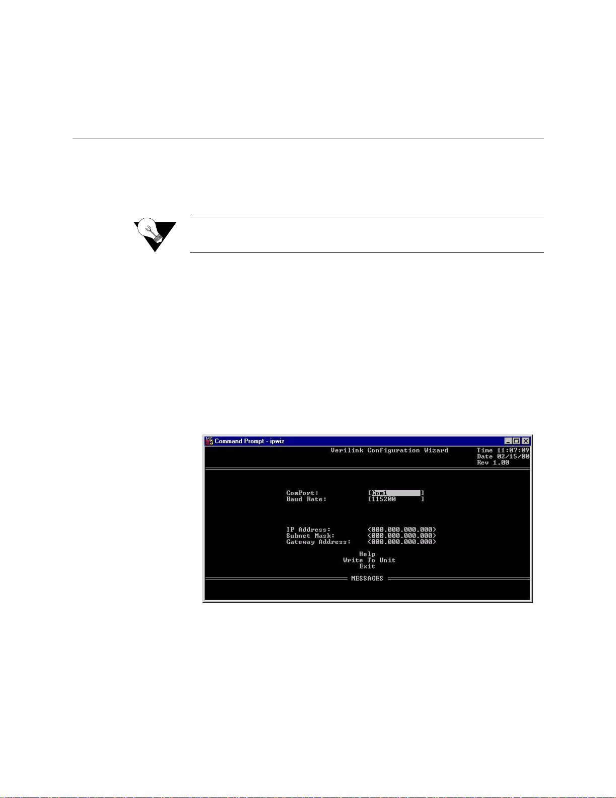
Double-click on this file to launch the program. After the program is fully
launched, you will see the following screen:
ipwiz.exe;
4 Using the Tab key to move fr om field t o fie ld, move the cursor to the “COM
Port” field. Using the Spacebar, toggle between the available options until
the correct COM port is sho wn (COM1, COM2, COM3, or COM4). Be s ure
to choose the same COM port as the port to which the unit is connected.
2-2 WANsuite 6450
5 By default, the “Baud Rate” field will display 115200 (bits per se cond). For
the purpose of this installa tion, do not change the displayed baud rat e from
its default. Proceed directly to the next step.
Page 27

6 Using the Tab key again, move the cursor to the “IP Address” field and
enter the appropria te IP Address for the unit (xxx.xxx.xxx.xxx). If necess ary ,
repeat this process for the “Subnet Mask” and “Gateway Address” fields.
7 Next, move the cursor to the “Write To Unit” field and press the Enter key.
The program will prompt you to reset the unit.
8 To reset the unit, press the RESET button on the unit’s front panel. The
Configuration Wizard will then automatically download the confi guration
information to the unit.
9 Note the status messages displayed at the bottom of the Configur ation
Wizard screen. When the download is complete, your PC will beep and the
status message bar will displa y “Finished.”
10 Finally, move the cursor to the “Exit” prompt and press Enter. The
Configuration Wizard pr ogram will close.
Installation 2-3
Page 28

2-4 WANsuite 6450
Page 29

C HAPTER
3
C
HAPTER
3
W
EB
S
ERVER INTERFACE
The WANsuite 6450 has an innovative, embedded Web-based user interface
for remote configuration and real-time reporting via Microsoft Internet
Explorer 5.0 or higher. Access to the Web server interface and how the
interface is used to configure the WANsuite 6450 unit are described in detail
below.
NOTICE: Verilink recommends the use of Microsoft’s Internet Explorer 5.0 or
higher because if you use other Internet browsers to access the Web
server interface , some screen element s will not displ ay as described in
this manual.
NOTICE: The material presented in this chapter follows the order listed in the
navigation bar on t he left side of the Web Server interface screen.
However, because the parameters you specify in the Service Table
attach proto cols to inter faces , you m ust c onfig ure t he Serv ice Table
first. (See Services as described on page 3-27.) You will not be able to
allocate channels (see Channel Table Details Screen as described on
page 3-59) un til the Service Table has been configured.
Configuration through the VT100 interface is covered in Chapter 4.
Web Server Interface 3-1
Page 30

Web Server Access
You can access the Web Server interface by connecting to its IP address. This
connection can be directly through the 10/100 Ethernet port, in-band via PPP
over any port, or in-band via encapsulated IP traffic on the ATM WAN
circuit.
NOTICE: Any changes to the unit’s configuration MUST be followed by a
“Submit” if there is a “Submit” button on the menu. If you
change the Service Table, you must perform a “Save and
Restart.”
To access the Web Server interface, type th e unit’s IP address in the
browser’s Address (or Location) field and press the “Enter” key.
Layout of Interface Screens
When you first access the Web Server interface, your browser will display a
screen that is divided into three frames. The upper frame forms a border
across the top of the screen; it identifies the Verilink unit in service and
displays the hardware and software revision and serial numbers under which
the unit is operating. The far right corner of the upper frame displays whether
or not a “Save an d Restar t” is nece ssary when param eters are change d on the
currently displayed screen.
Unit Screen
The area beneath the upper frame is divided into two side-by-side frames. The
frame on the left side of t his area d epicts a hierarch ical “tree” structure used
to navigate through the various interface screens. Each “branch” on the tree
guides you to more specific upper-level information about the unit and its
configuration. Note that the Interfaces, Applications, and Utilities branches do
not link to a page − these branches simply provide structure for navigation.
The frame on the right side of the screen will display the actual configuration
screen. The screen captures throughout this chapter show only the
configurat ion portio n of the screen, except in t he case of the Un it screen ,
which sh ows all t hree frames . The Un it screen represe nts the to p of the
navigation tree.
The first screen displayed by the unit’s Web Server interface is the Unit
screen (Figure 3.1). This screen lets you view and set specific information
about the unit in service.
3-2 WANsuite 6450
Page 31

Figure 3.1
Unit Screen
The Unit screen displays the following fields:
Field Function
Object ID Display-only field used to point an SNMP agen t to this ID.
Up Time Displays the amount of time the unit has been up and running.
Contact Stores the name of a point-of-contact for system failure.
Name Read/write field that holds the unit’s name.
Loca ti o n Read /w r i te field that holds th e u ni t 's lo c a t io n .
FrameStart ID Not used for ATM. Read/write field that holds the unit's ID that
uniquely identifies the unit and is used in the FrameStart
applications.
Operating Mode Displays most r ecently execute d Maintenance Reset option.
Blank Fields Read/write fields for user-specific labels and values. Inform ation
resides in non-volatile memory.
Time Read/write field that holds the unit's internal time setting in
standard 24-hour HH:MM:SS format.
Date Read /w r i te field that hold s th e u nit's int er n al date se tt in g in
standard MM/DD/YY format.
The Unit screen provides the following user-activated buttons:
Button Function
Submit Sets any values that have been changed. Use the top “Submit”
button to set unit parameters changed in the upper section of the
screen, and the lower “Submit” button to set the re al-time clock.
Web Server Interface 3-3
Page 32

Button Function
Maintenan ce Reset Resets unit to its default configurat ion.
Save and Restart Saves the c urrent configuration and restarts the unit.
Maintenance Reset
Use this button to perform a Maintenance Reset. All configurations will be
lost and the unit will be set back to an initial factory configuration. The
options for a Maintenance Reset are shown in the table below.
RFC 1483
Configuration
Choice
Ethernet Yes Yes No None None None
Serial HDLC Yes No Yes None None None
E1 CCS* Yes Yes No None 1−31 None
E1 CAS Yes Yes No None 1−15, 17−31 None
Unframed E1 Yes Yes No None 0−31 None
T1 ESF Yes No Yes 1−24 None None
T1 SF Yes No Yes 1−24 None None
T1 ESF CAS/RBS Yes No Yes 1−24 None None
T1 SF CAS/RBS Yes No Yes 1−24 None None
Unframed T1 Yes No Yes 1−24** None None
Serial CES Yes Yes No None None 1−31
Unstructured Serial
CES
PPoA-IPCP No Yes No None None None
PPoA-NAPT No Yes No None None None
Encapsulated
Data
Yes Yes No None None 0−31
IP
Encapsulated
in ATM
Serial HDLC
Encapsulated
in ATM
T1 CBR
Channels
E1 CBR
Channels
Serial CBR
Channels
* Factory default configuration
** Unframed T1 CES service uses a n additional 8 kbps of bandwidth for framing
All the factory configurations set up an ATM service on the Network port
with one configured virtual channel (VPI=0, VCI=32). Management data
received on this channel (either WEB or SNMP) will be processed at the unit
if it is encapsulated using RFC 1483 and directed to the unit’s IP address. (A
Maintenance Reset will not change the unit’s IP address.)
The Serial HDLC configuration and the T1 ESF configuration will also accept
PPPoA encapsulated data and deliver it to the Serial port.
The T1 SF, T1 ESF CAS/RBS, T1 SF CAS/RBS, Unframed T1, Serial CES,
and Unstructured Serial CES configurations set up a CES service between the
Network port and the T1/E1 CBR port or the Serial port using VPI=0,
VCI=33. The T1 options configure the CBR port for the desired framing
mode, and configure the CES service for 24 channels. For unframed T1
service, the CES service provides 1.544 Mbps of bandwidth for the service
3-4 WANsuite 6450
Page 33

(1.536 Mbps for the T1 channels and 8 kbps for framing). The E1
configurations set up the CBR port to run E1 and have 30, 31, or 32 channels
delivered to the CES service. The Serial CES configurations set up the CBR
port to run E1 CCS or Unframed E1, but allocates all 31 or 32 channels to the
Serial port.
The PPoA-IPCP and PPPoA-NAPT set up a PPP connection over ATM using
the VPI=0, VCI=32. The resulting PPP interface then uses PPP negotiation to
obtain the IP address, mask, and DNS address. After successful negotiation,
the DHCP server starts on the Ethernet Lan. For PPPoA-IPCP, the negotiated
IP address is appli ed to th e LAN, w hereas in the case of PPP oA-NAPT , the
negotiated IP address is applied to the WAN.
Clicking the “Maintenance Reset” button will display a selection screen, as
shown in Figure 3.2, with a drop-down list of the available configurations,
which are listed in the table above.
Figure 3.2
NOTICE: Performing a “Maintenance Reset” or a “Save and Restart” will
Save and Restart
The Save and Restart button on the Unit screen will display the confirmation
screen shown in Figure 3.3.
Figure 3.3
Maintenance Reset Screen
terminate communications with the unit.
Save and Restart Screen
Click the “Save and Restart” button on the confirmation screen to proceed
with the action. To cancel, simply invoke your browser’s “Back” function.
Web Server Interface 3-5
Page 34

Interfaces
Network
The WANsuite 6450 unit has five available interfaces: Network, CBR, Serial,
Ethernet 10/100, and Supervisory. These interfaces are described below.
The WANsuite 6450 Network screen (Figure 3.4) lets you view and make
changes to the Network interface's configuration.
Figure 3.4
The Network screen status and configuration parameters are described in the
following paragraphs.
Network Screen
Unit Type
Expected Repeaters
Span Configuration
3-6 WANsuite 6450
Selects the unit type. TU-R represents a CPE terminal unit; TU-C represents a
CO te rmina l unit .
Values: TU-R, TU-C
Default: TU-R
Provisions the num ber of re peaters in the sel ected s pan.
Values: 0 (zero )
Default: 0 (zero)
Represents a span configuration profile in the Span Configuration Profile
Table, which applies to this span. By default, this object will have the value
“DEFVAL” (the index of the default profile).
Values: User Span Profile 1, User Span Profile 2, DEFVAL (Default
Value)
Default: DEFVAL
Page 35

Span Alarm
Configuration
Represents an Alarm configuration profile in the Endpoint Alarm
Configuration Profile Table. The alarm threshold configuration in the
referenced profile will be used by default for all segment endpoints in this
span. By default, this object will have the value 'DEFVAL' (the index of the
default profile).
Values: User Alarm Profile 1, User Alarm Profile 2, User Alarm
Profile 3, DEFVAL (Default Value)
Default: DEFVAL
Pair-1 Mode
Pair-2 Mode
EOC In
EOC Out
Discovered Repeaters
Line Rate
Maximum Line Rate
Transmission Mode
Represents the status and detail status information of the span for two-wire
operation.
Represents the status and detail status information of the span for four-wire
operation. This mode is not supported by the WANsuite 6450.
Displays the number of messages received on the Embedded Operations
Channel.
Displays the number of messages transmitted on the Embedded Operations
Channel.
Displays the number of discovered repeaters in this span.
Displays the actual negotiated line rate.
Displays the maximum physical line rate with respect to the current span
configuration.
Displays the actual transmission mode (Annex-A or Annex-B).
The Network screen provides the user-activated buttons described below.
Button Function
Submit Sets any values that have been changed.
Configuration Pr ofiles Displays the three configuration profiles that can be used.
Alarm Profiles Displays the four alarm profiles that can be used.
Span Endpoints Lists the currently availab le span endpoints.
CAUTION: Performance data will be lost upon power cycle or after performing a
Maintenance Reset/Restart.
Configuration Profile Table Screen
Clicking on the “Configuration Profiles” button on the Network screen will
display the table shown in Figure 3.5.
Web Server Interface 3-7
Page 36

Figure 3.5
Configuration Profile Table Screen
This table displays the information the user specifies in the Configuration
Profile Details screen (Figure 3.6), which is accessed by clicking on the
specific Profile Name hyperlink in the table above.
Wire Mode
Data Rate (Min)
Figure 3.6
Configuration Profile Det ails Screen
This screen lets you configure or change the following information about the
selected configuration profile:
Displays the type of wire interface used by the span. The WANsuite 6450
supports only the two-wire mode.
Sets the minimum attainable data rate in the span.
Data Rate (Max)
Remote
Transmission Mode
3-8 WANsuite 6450
Sets the maximum attainable data rate in the span. Note that the line rate will
be 8 kbps above the data rate.
Enables/disables support for remote management of the units in an SHDSL
line from the STU-R via the EOC.
Values: Enabled, Disabled
Default: Enabled
Sets the regional setting of the span represented as a bit-map of possible
settings.
Values: Annex-A ( ITU-T G.991.2), Annex-B (ITU-T G.991.2)
Default: Annex-B
Page 37

NOTICE: When the WANsuite 6450 is operating with Unit Type set to TU-R, it
supports Annex-A or Annex-B. The configuration of the TU-C unit
determines the actual transmission mode used.
PSD Type
Line Probe
Sets the use of symmetric Power Spectral Density (PSD) mask.
Values: Symmetric
Default: Symmetric
Enables or disables rate adaptation line probe.
Values: Enabled, Disabled
Default: Enabled
To set any configuration profile parameter, enter the desired value/information
in a field or select the desired parameter from one of the pull-down lists, and
then click on the “Submit” button.
Alarm Profile Table Screen
Clicking on the “Alarm Profiles” button on the Network screen will display
the screen shown in Figure 3.7.
Figure 3.7
Alarm Profile Ta ble Screen
The Alar m Profiles screen d isplays the cur rent values of SHD SL alar m
thresholds. Click on the specific hyperlink under “Profile Name” to configure
the alarm threshold values to be used for the selected segment endpoint in the
“Alarm Profile Details” screen shown in Figure 3.8.
Web Server Interface 3-9
Page 38
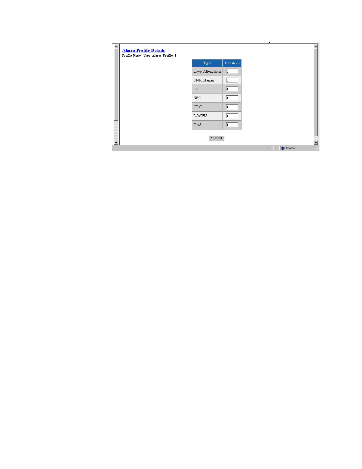
Figure 3.8
Alarm Profile Details Scre en
Loop Attenuation
SNR Margin
ES
SES
CRC
Sets the loop attenuation alarm threshold. If the current value reaches or
exceeds this threshold, a crossing trap is generated. A value of 0 (zero)
disables the trap.
Sets the Signal-to-Noise Ratio margin alarm threshold. When the current SNR
value reaches or drops below this threshold, a crossing trap is generated. A
value of 0 (zero) disables the trap.
Sets the threshold for the number of Errored Seconds within any given 15minute performance data collection interval. If the value of ES in a particular
15-minute collection interval reaches/exceeds this value, a trap is generated.
One trap will be sent per interval per endpoint. A value of 0 (zero) disables
the trap.
Sets the threshold for the number of Severely Errored Seconds within any
given 15-minute performance data collection interval. If the value of SES in a
particular 15-minute collection interval reaches/exceeds this value, a trap is
generated. One trap will be sent per interval per endpoint. A value of 0 (zero)
disables the trap.
Sets the threshold for the number of Cyclic Redundancy Check anomalies
within any given 15-minute performance data collection interval. If the value
of CRC anomalies in a particular 15-minute collection interval reaches/
exceeds t his value , a trap is generated . One trap will be sent per interv al per
endpoint. A value of 0 (zero) disables the trap.
LOSWS
Sets the threshold for the number of Loss of Sync Word Seconds within any
given 15-minute performance data collection interval. If the value of LOSW
in a part icular 15-m inute co llection in terval reac hes/ex ceeds this value, a trap
is generated. One trap will be sent per interval per endpoint. A value of 0
(zero) disables the trap.
UAS
Sets the threshold for the number of Unavailable Seconds within any given
15-minute performance data collection interval. If the value of UAS in a
3-10 WANsuite 6450
Page 39

particular 15-minute collection interval reaches/exceeds this value, a trap is
generated. One trap will be sent per interval per endpoint. A value of 0 (zero)
disables the trap.
NOTICE: Any changes to the above-listed parameters must be followed by a
“Submit” for the changes to take effect.
Span Endpoints Screen
Clicking on the “Span Endpoints” button on the Network screen will display
the screen shown in Figure 3.9.
Figure 3.9
Span Endpoint Table Screen
This screen displays each endpoint of the span. If the SHDSL link is not up,
only the local side of the span is displayed. The EOC channel is used to
access th e remote end uni t
Clicking on the highlighted (linking) Type identifier in the table on the Span
Endpoints screen will display the Span Endpoints Details screen (Figure 3.10).
This table supports retrieval of unit inventory information available via the
EOC from units on an SHDSL line, and provides details regarding the
paramete rs listed be low.
Figure 3.10
Span Endpoint Details Screen
Vendor ID
Model Number
Serial Number
Displays the Vendor ID as reported in an Inventory Response message.
Vendor model number as reported in an Inventory Response message.
Vendor serial number as reported in an Inventory Response message.
Web Server Interface 3-11
Page 40

EOC Software Version
Vendor EOC version as reported in a Discovery Response message.
Standard Version
List Number
Issue Number
Software Version
Equipment Code
Transmission Mode
Capabilit y
Endpoint Side
Wire Pair
Version of the SHDSL standard implemented as reported in an Inventory
Response message.
Vendor list number as reported in an Inventory Response message.
Displays the Vendor issue number as reported in an Inventory Response
message.
Displays the Vendor software version as reported in an Inventory Response
message.
Equipment code conforming to ANSI T1.213, Coded Identification of
Equipment Entities.
Transmission mode capability of the SHDSL unit.
Defines which direction the SHDSL port is pointing. Normal operation will
use the TU-R configuration, and the endpoint will be “Network.” When unit
type is TU-C, endpoint will be “Customer.”
Always “Wire Pair 1.”
Status
Clicking on the “Span Endpoint Performance/Summary” button on the Span
Endpoint Details screen will display the screen shown in Figure 3.11.
Figure 3.11
Span Endpoint Performance/Summary Scre en
This screen display s inform atio n on the perform anc e and error s tatus of a s pan
endpoint. This information is provided in summary form for complete totals
as well as for current 15-minute and 1-day intervals.
Current state of the endpoint. This is a string indicating possible conditions.
The various string components are as follows:
OK − There no defects on the line.
3-12 WANsuite 6450
SNR − Indicates that the SNR margin has dropped below the alarm
threshold.
Page 41

Attenuation − Indicates that the loop attenuation has exceeded the alarm
threshold.
LOSW − Indicates an LOSW alarm.
Loopback − A loopback is currently active at thi s Segment Endpoint.
SNR Margin
Loop Attenuation
Time Elapsed
ES
CRC
LOSWS
SES
UAS
Current Signal-to-Noise Ratio margin for this endpoint as reported in a Status
Response/SNR message.
Current loop attenuation for this endpoint as reported in a Network or
Customer Side Performance Status message.
Total elapsed seconds in the current 15-minute interval.
Count of Errored Seconds on this endpoint since the unit was last restarted.
Count of Cyclic Redundancy Check anomalies on this endpoint since the unit
was last restarted.
Count of Loss of Sync Word Seconds on this endpoint since the unit was last
restarted.
Count of Severely Errored Seconds on this endpoint since the unit was last
restarted.
Count of Unavailable Seconds on this endpoint since the unit was last
restarted.
15-Minute and 1-Day Intervals
Also included on this screen are buttons used to display the span endpoint
performance summaries for 15-minute intervals and for 1-day intervals. These
screens display only a summary of the errors (ES, SES, CRC, LOSWS, UAS)
that have occurred on the span during the interval selected.
The 15-Minute Intervals table provides one row for each endpoint
performance data collection 15-minute interval. The 1-Day Intervals screen
provides one row for each endpoint performance data collection 24-hour
interval.
Span Endpoint Maintenance Screen
Clicking on the “Span Endpoint Maintenance” button from the Span Endpoint
Details screen will dis play the screen shown in Figure 3.12. This table supports
maintenance operations (e.g., loopbacks) to be perform ed on segment
endpoints.
Web Server Interface 3-13
Page 42

Figure 3.12
Span Endpoint Maintenance Screen
The Span Endpoint Maintenance parameters are described below.
Loopback Timeout
Restart Endpoint
Tip Ring Reversal
Power Source
CBR
(minutes)
Loopback
Specifies the timeout value in minutes for loopbacks initiated at this endpoint.
A value of 0 disables the timeout.
Specifies loopbacks for the associated segment endpoint.
Values: No Loopback, Normal Loopback
Default: No Loopback
Enables the manager to trigger a soft restart of the SHDSL line at the
associated segment endpoint. Set this object to “restart” to initiate a restart. A
restart will occur after approximately 5 seconds.
Values: Ready , Restart
Default: Ready
Indicates the state of the tip/ring pair at the associated segment endpoint.
Indicates the DC power source being used by the associated unit.
CAUTION: The T1/E1 CBR port is not a standalone port. Connect the T1/E1 CBR
port only to the "private" side of the network on the customer
premises, never to the "public" side.
Click on the CBR link on the navigation pane on the left-hand side of the
Unit screen to display the CBR screen (Figure 3.13). The CBR screen (Figure
3.13) lets you view and make changes to the CBR interface’s configuration as
described below. In addition, this screen provides a table that displays error
status and alarm thresholds for the CBR int erface.
3-14 WANsuite 6450
Page 43

Figure 3.13
CBR Screen
T1/E1 Framing
T1/E1 Coding
T1 PRM
Selects the framing for the network side of the DSU/CSU.
Values T1 ESF, T1 D4, E1 CCS, E1 CAS
E1 Unframed, T1 Unframed
Default: T1 ESF
NOTICE: To set unit to Signaling mode, you must first configure the following: on
the CBR screen (page 3-14), configure Framing; on the Channel Table
Details screen (page 3-59), set Rate to 56k/Signaling, and on the CES
Service Details screen (page 3-53), configure AAL1 Format.
Sets the CBR interface line coding.
Values: HDB3, AMI, B8ZS
Default: B8ZS
NOTICE: For a T1 CBR Maintenance Reset, the default is T1 ESF. The T1/E1
coding default is B8ZS.
Lets you establish which performance messaging standard will be employed
to initiate Performance Report Message (PRM) functions. Setting this field to
“Enable” instructs the unit to use ANSI T1.403, which sends a PRM once
every second. Setting this field to “Disable” instructs the unit to use AT&T
TR54016, which provides performance reporting on request only.
Values: Disable, Enable
Default: Disable
Web Server Interface 3-15
Page 44

T1 Zero Suppression
Determines whether ones density insertion is activated after 15 zeros. This
parameter is ignored if the Coding parameter is set to “B8ZS.”
Values: Disable, Enable
Default: Disable
T1 Mode
T1 Line Build Out
T1 DSX Level
E1 CRC4 Mode
As a T1, the unit will operate in either long-haul or short-haul mode.
Values: Short-Haul, Long-Haul
Default: Short-Haul
Sets the transmit Line Build Out (LBO) for the CBR interface.
Values: 0, −7.5, −15.0, −22.5 dB
Default: 0 dB
Specifies the T1 DSX output level.
Values: 0−110, 111−220, 221−330, 331−440, 441−550, 551−660, >661 ft
Default: 0−110 ft
Provides line integrity detection to determine if bit errors are present on the
line.
Values: Disable, Enable
Default: Disable
Error Status and Alarm Thresholds Table
The unit can be programmed to generate an alarm condition based on a
specific level of performance degradation. The CBR screen presents a table
that provides current error status and alarm threshold information.
Acceptable alarm thresholds are set for periods of 15 minutes (900 seconds)
and sampled every second. The error types listed in the following paragraphs
can be preset to a value between 0 and 900 seconds. Setting a field to “0”
(zero) dis ables the a larm on that st atistic. To effectivel y disab le alarm
reporting , set all fields to “0” (zero).
The 15-minute time frame is not based on the TR 54016 or T1.403 interval
boundaries, but is a time window based on the accumulated counts over the
previous fifteen 1-minute intervals. In all cases, if the number of actual
network errored seconds in the previous 15 minutes reaches the preset
threshold for the specified error type, an alarm condition is declared.
The four columns o f the s tatus tab le are as follows:
• Status: Displays the current status of the CBR port.
• Alarm: Display s the alarm value of the network port. The unit declares an
alarm as soon as the count exceeds the threshold set.
• Count: Display s the number of even ts or occurrences of this statistic that
have been dete cted .
• Threshold: Displays a read/write field that can be set to a desirable
threshold.
The table provides error sta tus and al arm thre shold in formation f or the
following error pa rameters:
3-16 WANsuite 6450
Page 45

ES
Sets the Errored Seconds (ES) threshold. An ES is a 1-second period in which
at least one logic error occurred. The default value is 45 seconds.
SES
LOSS
UAS
CSS
BPVS
OOFS
AISS
Sets the Severely Errored Seconds (SES) threshold. An SES is a 1-second
period in which at least 320 CRC errors or one Out- of - Frame (OOF) error
occurred. The default value is 5 seconds.
Sets the Loss of Signal Seconds (LOSS) threshold. A LOSS is 1-second
period in which the T1/E1 received signal is interrupted. The default value is
5 seconds.
Sets the Unavailable Seconds (UAS) threshold. A UAS is a 1-second period
in which consecutive severely errored seconds cause an unavailable state. The
default is 0 seconds (Disabled).
Sets the Controlled Slip Seconds (CSS) threshold. The default is 0 seconds
(Disabled).
Sets the Bipolar Violation Errored Seconds (BPVS) threshold. A BPVS is a 1second period in which at least one bipolar violation occurred. The default is
0 seconds (Disabled).
Sets the Out of Frame Seconds (OOFS) threshold. An OOFS is a 1-second
period in which a frame sync loss occurred. The default value is 5 seconds.
Sets the Alarm Indication Signal Seconds (AISS) threshold. An AIS is a 1second period when unframed all ones are received. The default is 0 seconds
(Disabled).
RAS
Reset Timer
Sets the Remote Alarm Seconds (RAS) threshold. An RAS is generated by
the terminal equipment when an improper signal is received from the facility
(or upon receipt of unframed all ones). The default is 0 seconds (Disabled).
Sets the Reset Timer threshold. This field is the contiguous number of
seconds that an alarm parameter must be clear before the alarm is reset.
Applicable values range from 000 through 900. A value of “000” means the
alarm will never be reset.
The CBR screens provide the user-activated buttons described below.
Button Function
Submit Sets any values that have been changed.
Clea r Al ar ms Reset s th e al ar m conditi o ns and count s to zer o .
Perfor mance Displays a Performance/S u mmary screen that shows a current
count of the number of error events that have occurred over the
past 24 hours and the past 30 days.
CAUTION: Performance data will be lost upon power cycle or after performing a
Maintenance Reset/Restart.
Web Server Interface 3-17
Page 46

Figure 3.14
Perf ormance/S ummar y Scree n
In addition to the error parameters found in the Error Status and Alarm
Thresholds Table as described on page 3-16, the following error parameters
are inclu ded on th e Perfor mance/Sum mary t able:
BES
LOFC
CRCES
Sets the Bursty Error Seconds (BES) threshold. A BES is a 1-second period
during which at least more than one but fewer than 320 CRC6 errors
occurred.
The Loss of Frame Count (LOFC) represents the number of time a loss of
frame is declared. A loss of frame is declared after 2.5 seconds of continuous
loss of signal or OOF.
Sets the Cyclic Redundancy Check Errored Seconds (CRCES) threshold. A
CRC is a method of confirming the integrity of received data.
Beneath the Perf ormance/Sum mary table are tw o buttons: “Perform ance 24
Hour” and “Performance 30 Day.” Clicking either of these buttons will
display a detailed summary of the error events that have occurred during each
15-minute interval of the past 24 hours (Figure 3.15) or during each interval
(day) of the past 30 days (Figure 3.16).
3-18 WANsuite 6450
Page 47

Figure 3.15
Perf ormance 24 H o ur Screen
Serial
Figure 3.16
Perf ormance 30 D a y Screen
The Serial screen (Figure 3.17) lets you view and make changes to the unit’s
Serial interface configuration as described in the paragraphs below. To make
changes to any Serial port parameter, simply set the parameter to the desired
selection and press the “Submit” button.
Web Server Interface 3-19
Page 48

Figure 3.17
Serial Screen
Type
Mode
Selects the t ype of i nterfa ce (ba sed o n its elect rical signal charact erist ics) us ed
by the equipment connected to the Serial port.
Values: V.35, V.36, RS-232, EIA-530, and X-21
Default: V.35
NOTICE: V.35 requires the use of an optional cable. Refer to "Connector Pin
Assignments" on pageA-6 for ordering information.
By default, the Serial port serves as a DCE port. However, the Serial port can
serve as a DTE port.
If the Serial port connects to a DTE device (such as a FRAD or a router), the
Mode parameter must be set to “DCE.” If this port connects to a DCE device
(such as a DSU/CSU), this parameter must be set to “DTE.”
Values: DCE, DTE
Default: DCE
NOTICE: DTE mode requires the use of an optional DTE cable. Refer to
"Connector Pin Assignments" on page A-6 for ordering information.
NOTICE: When you configure the Serial port for CES, you must set the port mode
Packet Rate
3-20 WANsuite 6450
Packet Rate must be configured to the desired port speed (in bits per second).
This parameter is only applicable when the Serial port service type is not
CES.
to DCE .
Values: 64−2304 kbps
Default: 2048 kbps
Page 49

Bundling
Selects whether the DTE channel assignment is made as a “Contiguous”
group or as “Alternate” channels. Selecting “Alternate” ensures ones density.
Because the unit allows individual channels to be configured for a service, a
value of “Arbitrary” will be returne d for this parame ter if the current channel
allocation is not contiguous or Alternate. The “Arbitrary” value can only be
supplied by the unit − it cannot be set by the user.
Values: Contiguous, Alternate, Arbitrary
Default: Contiguous
NOTICE: Because “Alternate” Bundling assigns every other channel, only half
the channels are available.
Start Channel
Number of Channels
Format
Tx Clock
Selects the start ing channel in the CES Ch annel Table. (Re fer to Channel
Table Details Screen as described on page 3-59.) Starting with the specified
channel, the unit automatically assigns the channels that follow.
Values: 1−24 for T1; 0−3 1 for E1
Default: 1
Specifies the number of channels to be assigned to CES.
Values: 0−24 for T1; 0−3 2 for E1
Default: 0
NOTICE: Bundling, Start Channel, and Number of Channels apply only when the
Serial port service type is CES.
Selects the port’s operating mode.
Values: Sync, Async
Default: Sync
Selects the clock the unit uses to sample the data transmitted from the DTE.
When se t to “ In tern al, ” th e da ta i s sa mple d d irec tly with th e tr ans mit d ata
clock that is also supplied to the DTE as Transmit Clock. The “External”
option uses the external clock from the DTE.
Values: Internal , Extern al
Default: Internal
Tx Invert Clock
Flow Cont rol
NOTICE: The “External” option is valid only in Packet mode.
Changes the clock edge used to sample data received from the DTE.
Values: Disable, Enable
Default: Disable
Selects the type of flow control to be used if the port is asynchronous.
Values: None, Xon/Xoff, RTS/CTS
Default: None
Web Server Interface 3-21
Page 50

Character Size
Selects the number of bits required to make up one asynchronous character.
Values: Five, Six, Seven, Eight
Default: Eight
Parity
Stop Bit
RTS
RTS/CTS Delay
CTS
Sets the parity bit.
Values: None, Odd, Even
Default: None
Selects the number of bits required to end the asynchronous character.
Values: 1, 2
Default: 1
Request To Send determines the source from which the unit reads the RTS
signal status. If set to “Normal,” the unit gets RTS from the DTE on the
Serial in terface. If set to “Fo rced Tr ue,” RTS is alway s perce ived as “O n.”
Values: Normal, Forced True
Default: Normal
Request To Send/Clear To Send determines how long the unit waits before it
changes the level of CTS to match RTS when the CTS parameter is set to
“Internal.”
Values: Normal (~30 ms delay), Long (~100 ms delay)
Default: Normal
The Clear To Send can be set to “Forced True,” “Forced False,” or “Internal.”
If thi s par ame ter is set to “Int ern al, ” the CT S co ntr ol lea d fo llow s the Req ues t
to Send (RTS) control lead from the DTE after a delay of a duration
established by the RTS/CTS Delay parameter (see RTS/CTS Delay as
described on page 3- 22).
Values: Forced True, Forced False, Internal
Default: Forc ed True
DCD
Data Car rier Detect can be set to “Fo rced Tr ue,” “Fo rced Fa lse,” or
“Internal.” If set to “ Internal ,” DCD i s “On” when ne twork car rier is bei ng
received from the remote end, and is “Off” when network carrier is not being
received fr om the far end.
DSR
Data Set Ready can be set to “Forced True,” “Forced False,” or “Internal.”
The “Internal” option sets DSR “On” if the port is enabled and “Off” if the
port is disabled.
Current Pin Status
3-22 WANsuite 6450
Displays the Current Pin Status of the DTE Serial port pins.
Values: Forced True, Forced False, Internal
Default: Forc ed True
Values: Forced True, Forced False, Internal
Default: Forc ed True
Page 51

DTR Alarm Control and Status Table
In addition to the configurable fields, the Serial screen displays a table that
lets you set the Data Terminal Ready (DTR) Alarm Control parameters and
view the c urrent DT R Alarm Status.
Choices for DTR Alarm Control are “Enable” and “Disable”; the default
setting is “Disable.” Setting DTR Alarm Control to “Enable” allows the unit
to generate an alarm upon loss of DTR, which occurs when the Serial port
detects that the DTR signal is low. The DTR Status field indicates the current
state of th e DTR alarm.
To make changes to a Serial port parameter, simply set the parameter to the
desired selection and press the “Submit” button.
10/100 Ethernet (IP Service Details)
The 10/100 Ethernet (IP Service Details) screen (Figure 3.18) lets you
configure the IP parameters described below.
Unit IP Address
Subnet Mask
Gateway IP Address
Figure 3.18
A unique Network address assigned to this unit.
Defines the Network portion of the unit’s IP Address.
IP Address of the default gateway (router) on the LAN side of the unit.
10/100 Ethernet (IP Service Details) Screen
DHCP Client
Client Identifier
Ethernet
If DHCP Client is enabled at power-up, the unit will request its IP, Mask, and
Gateway addresses from a DHCP server located on the LAN side of the unit,
and the unit will use these addresses. If the DHCP request is unsuccessful, the
unit will use the configured addresses shown on this screen.
Displays a unique identifier for a specific IP address.
Enables or disables a remote unit’s Ethernet port.
Web Server Interface 3-23
Page 52

Physical Add ress
Displays unique MAC address.
NOTICE: The first three address parameters above can also be configure d using
the Installation Wizard as described on page 2-2.
The “Change IP Service Details” button will take you to an IP Service Details
screen (Figure 3.19) where you can view any changes you have made and
verify your settings before submitting them by clicking the “Submit IP
Service Changes” button. The “Discard Changes” button allows you to
discard any changes you have made, and return to the previous screen to reset
the parame ters.
Figure 3.19
IP Service Details Scr een
To view details about the current condition of IP, ICMP (In and Out), TCP,
and UDP parameters, click on the “Ethernet Stats” button at the bottom of the
screen. The Ethernet Stats screen (Figure 3.20) contains no user-selectable
fields or options; it is simply a representation of the applicable MIB II
parameters.
3-24 WANsuite 6450
Page 53

Figure 3.20
Ethernet Stats Screen
Click on the Unit Access Table button on the Ethernet (IP Details) screen to
view the Unit Access Table (Figure 3.21), which specifies up to 10 different
IP networks that may access the unit’s parameters. If no IP networks are
supplied, any host may access the unit. Select any Index number on the table
to view the Unit Access Details (Figure 3.22) that correspond with that Index
number.
Figure 3.21
Unit Access Table
Web Server Interface 3-25
Page 54

Supervisory
Figure 3.22
Unit Access Details
The Supervisory screen (Figure 3.23) displays the current speed of the
Supervisory port interface along with other parameters as described below.
The Supervisory port supports only asynchronous character formats.
Speed
Character Size
Figure 3.23
Supervisor y Screen
Changes the Supervisory port speed (in bits per second).
Values: 1200, 2400, 4800, 9600, 19200, 38400, 57600, 115200
Default: 19200
Selects the number of bits required to make up one asynchronous character.
Values: Five, Six, Seven, Eight
Default: Eight
Diagnostic Messages
Parity
3-26 WANsuite 6450
Enables the Supervisory port to send out diagnostic messages upon power-up.
Sets the parity bit.
Values: Enable, Disable
Default: Enable
Values: None, Odd, Even
Default: None
Page 55

Stop Bit
Selects the number of bits required to end the character.
Values: 1, 2
Default: 1
Current Pin Status
Services
The Current Pin Status, which shows the state of the RS-232 pins, is also
displayed on the Supervisory interface screen.
The Services screen (Figure 3.24) provides a view of the unit’s defined
services and display s the In terface and Type p arameters for ea ch servic e.
Figure 3.24
The table in the cen ter of th e scree n displays the avai lable servi ces listed by
index number.
Services Scr ee n
Service Details Screen
Clicking on an index number under the Service Index column will display a
Service Details screen such as the one shown below (Figure 3.25). (In this
example, the selected service type is CES .)
Figure 3.25
From this screen, you can access and change the parameters listed below. The
new parameters are saved when you click on “Submit” and return to the
previous screen.
Service Details Scree n
Web Server Interface 3-27
Page 56

Interface
Selecting one of the interfaces will bring up a screen where you can view
interface p arameters . These s creens a re the s ame ones displayed when you
select a sub-menu from the Interfaces screen described earlier on page 3-6.
Type
Selecting one of the services listed under the “Type” column will bring up a
screen where you can view (and, in some cases, change) parameters for each
type of service. The details displayed depend on the type of service currently
in effect. These screens are shown and described below according to each
type of service.
In addition, the Service Details screen provides the following user-activated
buttons:
Button Function
Submit Sets any values that have been changed.
Interface Details Opens the Detai ls screen for the Interfa ce of the currently select ed
service.
Type Details Opens the Detail s screen for the Type of the currently selected
service.
Interface Details Button
Clicking the “Interface Details” button on the Service Details screen lets you
view inte rface param eters fo r the sele cted ser vice. Yo u will also see the
interface parameters for the selected service if you click on the interface under
the Interf ace column on the Services screen.
Type Details Button
Clicking the “Type Details” button on the Service Details screen will let you
view (an d, in some cases, c hange) interface p aramete rs for the specified
service. The details displayed depend on the type of service currently in effect
for the s elected se rvice. Yo u will se e this sam e screen if you click on t he
service u nder the Type col umn on the Serv ices screen . Type D etails scr eens
IP Service Details Screen
Access the IP Service Details screen by clicking the IP link under the Type
column on the Services screen. Both the IP Service Details and the Ethernet
Stats screens are described on page 3-23.
Frame Relay Service Details Screen
Click on “Frame Relay” under the “Type” column on the Services screen to
access th e Frame Relay Ser vice De tails screen (Figu re 3.26). This screen lets
you access the configuration parameters described in the paragraphs below.
3-28 WANsuite 6450
Page 57

Figure 3.26
Frame Relay Service Details Screen
Interface Type
Link Management
Max Frame Size
If this service is conn ected to a Frame Relay net work, the Interface T ype
should be set to “UNI” as it is the user side of a User-to-Network interface. If
it is connected to a FRAD/Router, the Interface Type should be set to “NI” as
it is the network side of a User-to-Network interface. If it is connected to an
equipment set for Network-to-Network interface, the Interface Type should be
set to “NNI.”
Values: UNI, NI, NNI
Default: UNI if interface is Network, NI if interface is Serial
Set this parameter to the link management used by the equipment connected
to it. If set to “Auto,” the unit will learn the link management type and
display it on the status portion of this screen.
Once it discovers the link management type, the unit should be set to the
discovered value so that subsequent unit or network re-initialization will be
faster.
Values: Auto, ANSI, CCITT, LMI, None
Default: ANSI
If Auto Diagnostic is set to “Yes,” the unit will discard received frames that
are larger than the maximum frame size. If Auto Diagnostic is set to “No,”
these large received frames will be sent, but will be counted in the Rx Invalid
statistics.
Values: 64–4096
Default: 2500
N1
There are two types of status inquiries: keep alive and full status requests. Set
this parameter to determine how many “keep alives” are sent between full
Web Server Interface 3-29
Page 58

status requests. (For example, if set to 5, every fifth status inquiry will be a
full status inquiry.)
Values: 1–255
Default: 5 if i nterface is Netw ork (UNI ), 6 if i nterface is Serial ( NI).
N2
The N2 counter specifies the total number of link reliability errors and
protocol errors that can occur during the sliding event monitor count defined
by N3. If this count is exceeded, the port is declared inactive.
Values: 1–255
Default: 3
N3
This counter represents a Monitored Events Count. For a network, a
monitored event is the receipt of a status inquiry message or the expiration of
the polling verification timer T2. For a FRAD, a monitored event is the
transmission of a status enquiry message. This parameter defines the size of
the sliding window used by the unit to determine whether a channel or user
device is active.
Values: 1–255
Default: 4
T1
This parameter specifies the number of seconds the unit waits between issuing
status inquiry messages.
Values: 5–30
Default: 10
RFC131 5 Trap
Normal Tx Queue Size
Default CIR (bps)
Default Be Rate (bps)
When this parameter is set to “Enable,” the unit will send the standard
RFC1315 frame relay DTE circuit state change trap every time a DLCI
changes state, provided at least one destination IP address for trap is
configured in the SNMP configuration.
Values: Disable, Enable
Default: Disable
Each Frame Relay service has two distinct transmit queues: one for normalpriority traffic and one for high-priority traffic. This parameter defines how
many normal priority frames can be put in front of a high-priority frame. The
software always checks for high-priority frames before placing normalpriority f rames in t he transm it queue. However , once t he fram es are in t he
hardware transmit queue, their order of transmission cannot be changed.
This is the Committed Information Rate (in bits per second) provided by your
frame relay service provider. The unit will apply this value to each DLCI
learned from the network side to gather statistics and to perform CIR
enforcem ent, if req uired. If a DLCI i s configu red with a CIR d ifferent from
the default, the DLCI configuration will be used instead.
Values: 0–1536000
Default: 0
This is the Excess Burst Rate (in bits per second) provided by your frame
relay service provider. The unit will apply this value to each DLCI learned
3-30 WANsuite 6450
Page 59

from the network side to gather statistics and to perform CIR enforcement, if
required. If a DLCI is configured with a different Excess Burst from the
default, the DLCI configuration will be used instead.
Values: 0–1536000
Default: 0
Enforce CIR and Be
Management DLCI
Managem ent Auto IP
DLCI
LMI Sourcing
If this parameter is set to “Yes,” the unit will enforce Committed Information
Rate and E xcess Burst.
Values: No, Yes
Default: No
NOTICE: The Auto Diagnostic parameter must be set to “Yes” to enforce CIR and
Be.
If there is a DLCI entered (and submitted) in this field, it will be the only
DLCI that looks for in-band management packets. If a value of “0” (zero) is
entered in this field, all DLCIs will look for management packets.
If this parameter is set to “Yes,” the unit will monitor the specified
management DLCI for 5 pings over 5 seconds, after which the unit uses the
destination address as its management IP address.
If this parameter is set to “Yes,” the unit will source LMI messages for that
service. Set this pa rameter to “Yes” if the service is not paired .
When set to “No,” the unit will not be the source of LMI messages for that
service. LM I mess ages will be exchan ged tr ansparentl y betwee n the paire d
services.
Values: No, Yes
Default: No
FrameStart Auto
Discovery
Round T rip D elay Size
(bytes)
NOTICE: If either side of the Frame Relay connection goes down, you will be
unable to remotely access any connected units.
When this parameter is set to “Yes,” the unit will send FrameStart discovery
and delay frames to each DLCI it learns as soon as the DLCIs are set active.
This is required to calculate round trip delay as well as to discover remote
WANsuite units. This parameter should be set to “Yes” only on services that
have a WANsuite at the far end of the frame relay connection. Also if set to
“Yes,” the unit will gather SLA parameters such as frame and data delivery
ratio as defined in the Frame Relay Forum Implementation, FRF.13. Those
gathered statistics are then displayed on the DLCI Statistics screen as shown
on page 3-39.
Values: No, Yes
Default: No
Specifies the frame size (in bytes) of packets making the round-trip.
Web Server Interface 3-31
Page 60

Round T rip Delay Rate
(secs)
Specifies the rate (in seconds) at which Round Trip Delay packets are sent.
Status and Alarms Table
The table displayed at the bottom of the Frame Relay Service Details screen
reports on the status and condition of LMI parameters and on Receive/
Transmit alarms and thresholds. Alarm threshold levels may be changed by
entering a new threshold value in the appropriate field of the table and
clicking the “Submit” button. Table fields are described below.
Active
LMI Type
FrameStart Status
Rx Invalid Thr eshold
Rx Invalid Alarm
Tx Threshold
Tx Alarm
Rx Threshold
Rx Alarm
Read-only field shows whethe r or not (Yes or No) an alarm is active.
Read-only status indicates ANSI, CCITT, LMI rev. 1, or Unknown.
Read-only status indicates Sourcing, Monitoring, or 0.
Number of invalid frames received during a 15-minute interval after which an
invalid alarm will be triggered. Default of “0” disables this alarm.
Status of t his alar m indicat es OK o r Alarme d.
Number of bits per second sent during a 15-minute interval after which a Tx
alarm will be triggered. Default of 0 disables this alarm.
Status of t his alar m indicat es OK o r Alarme d.
Number of bits per second sent during a 15-minute interval after which an Rx
alarm will be triggered. Default of 0 disables this alarm.
Status of t his alar m indicat es OK o r Alarme d.
The Frame Relay Service Details screen provides the following user-activated
buttons:
3-32 WANsuite 6450
Button Function
Submit S ets any values that have been changed.
Frame Relay Statis tics Opens the Frame Rel ay Port Statistics screen fo r th e current
Frame Relay servic e.
DLCI Table Opens the DLCI Table screen, which displays all the DLCIs
on the current service.
Clear Alarms Clears all Frame Relay alarms.
Pair Type Details Opens another Fram e Relay Servic e Details scr een that
reverses the service and the pair so that you can view both
sides of the pair.
Page 61

NOTICE: When a “Submit” command is executed, the Frame Relay link will be
re-initialized with the new parameters, causing a brief interruption in
data transfer.
Frame Relay Port Statistics Screen
Clicking the “Frame Relay Statistics” button brings up a table (Figure 3.27)
that reports on the status and condition of LMI parameters and on Receive/
Transmit alarms and thresholds. Alarm threshold levels may be changed by
entering a new threshold value in the appropriate field on the Frame Relay
Service Details screen and clicking the “Submit” button.
Figure 3.27
Frame Relay Port Statistics Screen
Frames
Octets
Mgmt Frames
Mgmt Octets
Stat Inquiries
Stat Response s
Transmit
Number of frames transmitted by the port.
Number of octets transmitted by the port.
Number of management frames transmitted by the port.
Number of management octets transmitted by the port.
Number of octets transmitted in frame relay LMI status inquiries.
Number of octets transmitted in frame relay LMI status responses.
Web Server Interface 3-33
Page 62

Receive
Frames
Octets
Mgmt Frames
Mgmt Octets
FECN
BECN
Invalids
Stat Inquiries
Stat Response s
Invalid LMIs
Peak
A verage
Period Index
Number of frames received by the port.
Number of octets received by the port.
Number of management frames received by the port.
Number of management octets received by the port.
Number of Forward Explicit Congestion Notification frames received.
Number of Backward Explicit Congestion Notification frames received.
Number of invalid frames received.
Number of octets received in frame relay LMI status inquiries.
Number of octets received in frame relay LMI status responses.
Number of invalid Local Management Interface frames received.
Throughput (bits /sec )
Peak bandwidth (in bps) as measured over a 10-second period.
Average bandwidth (in bps) used by the port.
Selects the interval (Current, Summary, or 1-96) to be viewed on the Frame
Relay Port Statist ics screen .
The Frame Relay Port Statistics screen provides the following user-activated
buttons:
Button Function
Submit Sets any values that have been changed.
All Frame Relay
Intervals
Type Details Returns you to the Frame Relay Service Details s cre en.
Clear S t at s Clears all Frame Relay sta ti s t ic s.
Opens the Frame Relay Statistics screen that sh o w s all statistics
for all parameters.
DLCI Table Screen
Clicking the “DLCI Table” button on the Frame Relay Service Details screen
to display a table of all DLCIs (Figure 3.28) on a specific frame relay service
along with their state and alarm conditions. You may create a new DLCI by
entering the DLCI name in the DLCI field at the top of the screen and
clicking the “Submit” button.
3-34 WANsuite 6450
Page 63

Figure 3.28
DLCI Table Screen
DLCI Details Screen
The DLCI Details screen (Figure 3.29) lets you access the configuration
parameters described in the paragraphs below. To bring up this screen, click
on a specific DLCI under the “DLCI” column on the DLCI Table screen.
Figure 3.29
DLCI Details Screen
Protocol Encapsulation
The unit uses the first three configuration parameters (Protocol Encapsulation,
Proprietary Traffic Type, and Proprietary Offset) displayed on this screen to
gather statistics. For in-band management, “RFC 1490” must be the
encapsulation method.
Type of encapsulation used by the FRAD/Router connected to the unit.
Values: RFC 1490, Proprietary, RFC 1490-Encryption
Default: RFC 1490
Web Server Interface 3-35
Page 64

Propriet ary Traffi c
Type
When Protocol Encapsulation is set for “Proprietary,” the Proprietary Traffic
Type parameter defines which protocol is encapsulated.
Values: IP, IPX, Ethertype, None
Default: None
Proprie tary Offse t
CIR (bps)
Be (bps)
Bc (bps)
When Protocol Encapsulation is set for “Proprietary,” the Proprietary Offset
parameter defines the number of octets after the frame relay header where the
proprietary traffic type starts.
Values: 0–64
Default: 0
If a Committed Information Rate is configured here, its value will be used
instead o f the defau lt CIR of the F rame Rel ay servi ce.
Values: 0–2048000
Default: 0
If an Excess Burst Rate is configured here, its value will be used instead of
the default excess burst of the Frame Relay service.
Values: 0–2048000
Default: 0
If CIR enforcement is configured to “Yes,” the unit will throttle the
committed burst down to this value when frames are received with the BECN
bit set.
Values: 0–2048000
Default: 0
Discard Eligible Flag
In Band Management
FrameStart Delay
FrameStart Status
If this parameter is set to “Yes” and CIR enforcement is also set to “Yes,” the
unit will set the Discard Eligible (DE) bit for frames sent over CIR.
Values: Yes, No
Default: No
If the unit is to be used as a gateway to reach a remote WANsuite 6450
through this DLCI, this parameter should be set to “Yes,” and the remote IP
address and Mask should be configured in the corresponding endpoint.
Values: Yes, No
Default: No
If this parameter is set to “Enable,” the unit will send FrameStart discovery
and delay frames on this DLCI, and will report the state of the remote
Verilink unit with FrameStart technology. It will also send SOS frames when
the FRAD/router connected to this unit goes inactive.
Values: Enable, Disable
Default: Enable if Auto Discovery is set to “Yes”; Disable otherwise
If the remote unit is a Verilink unit with FrameStart technology and
FrameStart Auto Discovery is enabled, the FrameStart Status field will show
the status of the remote unit. The status is “Active” if both the local and
3-36 WANsuite 6450
Page 65

remote DL CIs are a ctive an d the rem ote uni t answers to the discover y frames
sent by this unit. The status is “SOS” if the remote unit is active but the
FRAD/Ro uter con nected to it is in active. T he statu s is “Inac tive” in al l other
cases.
Values: Activ e, Inactive, SOS
Default: Inactive
Remote DLCI
Remote Unit
Remote Unit IP
Address
Round T rip D elay Size
(bytes)
Round T rip Delay Rate
(secs)
If the remote unit is a Verilink unit with FrameStart technology, and
FrameStart Auto Discovery is enabled, this displays the DLCI number used
on the remote end of this DLCI.
Values: 16−1023
Default: 0
If the remote unit is a Verilink unit with FrameStart technology, and
FrameStart Auto Discovery is enabled, this parameter gives the first three
digits of the unit ID configured on the remote end of this DLCI.
Values: 000−999
Default: 000
Displays the IP address of the remote Verilink unit with FrameStart
technology if FrameStart Auto Discovery is enabled.
Specifies the frame size (in bytes) of packets making the round-trip. If the
Round Trip Delay Size is not configured, the Frame Relay Details values will
be used.
Specifies the rate (in seconds) at which Round Trip Delay packets are sent. If
the Round Trip Delay Rate is not configured, the Frame Relay Details values
will be used.
Status
Receiving FECN/
BECN
CIR Threshold
DLCI Status Table
The bottom portion of the screen displa ys a table detailing the actual status of
DLCI and alarm threshold information as follows:
If this DLCI is up, the status will be “Active”; otherwise, the status will be
“Inactive.”
Values: Active, Inactive
Default: Inactive
When a frame is received with congestion bit set, this parameter is set to
“Yes.” It is set back to “No” when a frame is received without congestion bit
set.
Values: Yes, No
Default: No
Sets the Tx over CIR alarm threshold. This threshold is the number of bits per
second in excess of CIR during a 15-minute interval. Setting this field to “0”
(zero) disables the alarm.
Web Server Interface 3-37
Page 66

CIR Alarm
Reports if the Tx over CIR threshold has been exceeded.
Bits Over Be Threshold
Bits Over Be Alarm
Congestion Threshold
Congestion Alarm
BECN in CIR
UAS Threshold
UAS Alarm
Sets the Tx over Be alarm threshold. This threshold is the number of bits per
second in excess of CIR + Be during a 15-minute interval. Setting this field to
“0” (zero ) disables the ala rm.
Reports if the Tx over Be threshold has been exceeded.
Sets the Rx Congestion alarm threshold. This threshold is the number of
frames received with BECN/FECN. Setting this field to “0” (zero) disables
the alarm.
Reports if the Rx Congestion threshold has been exceeded.
Reports if Backward Explicit Congestion Notification (BECN) has been
received within CIR.
Sets the Unavailable Seconds (UAS) alarm threshold. This threshold occurs
after the DLCI is unavailable for a specified number of seconds. Setting this
field to “0 ” (zero) d isables t he alarm .
Reports if the UAS threshold has been exce eded.
The DLCI Details screen provides the user-activated buttons defined below.
Button Function
Submit Sets and activat es newly defined DLCI parameters.
Clea r Al ar ms Clears al l DL C I ala r ms .
DLCI Statistics Displays a table of the statisti cs for this DLCI.
DLCI Table Displa ys a ta ble of all DLCIs on a spec ifi c fr ame rel ay s ervi ce , with
their state and alarm condit i o ns.
Dele te DL CI Lets yo u d elete a specific DL C I .
DLCI Statistics Screen
Clicking the “DLCI Statistics” button on the DLCI Details screen will display
a summary (Figure 3.30) of the Transmit, Receive, and Performance statistics
for the s elected D LCI for a specific period.
3-38 WANsuite 6450
Page 67

Figure 3.30
There are ninety-six 15-minute buckets (sampled every second) available for
DLCI statistics. If the unit is powered on at 01:00 PM, the first interval will
be completed at 01:15 PM; subsequent intervals would be completed at xx:30,
xx:45, xx:00 and xx:15. Interval 1 is always the latest (most recent) interval,
and interval 96 will always be the oldest.
DLCI Statistic s Screen
The DLC I Statisti cs screen i n the pr eceding fi gure sh ows a sum mary t hat
includes all 96 buckets. You can choose to see the statistics for any given
bucket by selecting the desired Period Index from the pull-down menu and
clicking the “Submit” button. Alternatively, you can display all intervals at
once by clicking the “All DLCI Intervals” button beneath the table. The MIB
(ipadv2.mib) describes each avail able stat istic. “FD R” on th e screen a bove
refers to Frame Delivery Ratio, which is the ration of successful frame
receptions to attempted frame transmissions. “DDR” refers to Data Delivery
Ratio or the ratio o f succes sful payl oad bytes received to atte mpted pa yload
bytes transmitted. “DE,” or Discard Eligible, refers to the data that is first
eligible to be discarded when network congestion occurs.
ATM Service Details Screen
Access the ATM Service Details screen (Figure 3.31) by clicking on ATM
under the Type col umn on the Serv ices scr een. The A TM Ser vice Deta ils
screen lets you access the configuration parameters described in the
paragraphs below.
Web Server Interface 3-39
Page 68

Figure 3.31
The Configuration table on the ATM Service Details screen is used to set the
following configuration parameters:
ATM Service Details Scr een
• Max VCC (Virtual Channel Connection) – maximum number of Virtual
Channel Connections on this ATM link. The defaul t value is 4.
• Max VPI Bits – default Max Virtual Path Identifier Bits value is 8 for VPI
values ranging from 0 to 255.
• Max VCI Bits – default Max Virtual Channel Identifier Bits value is 16 for
VCI values ranging from 32 to 65535.
• Oversubscription Factor − current over-subscription factor for this ATM
interface. Used for VBR and UBR VC connection admissi on cont rol to allow
either the VBR or UB R service category c onnec tions to c ol lective ly use m ore
bandwidth than is available to make use of the statistical multiplexing of the
connections. Values range from 1 to 10. A value of 1 indicates no
oversubscription. A value of 5 indicates 5 times oversubscription of both
VBR and UBR is permitted.
NOTICE: CBR connections cannot be oversubscribed Also, if CES is in use on the
interface, PCR is limited for all AAL5 connections to the amount the
line rate can support above the commitment for CES, and the
oversubscription applies only to bandwidth above the CES commitment.
To change an ATM Service configuration, enter the desired value for each
parameter and click on the “Submit” button.
The Status table provides the following status information on the circuits:
• OperStatus (Operation Status) − current operational status for the ATM
3-40 WANsuite 6450
interface.
Page 69

• Opened VCCs − current number of open virtual channel connections.
• Unopened VCCs − current number of unopen virtual channel connections.
• Line Bandwidth − current line bandwidth on the ATM Network interface
expressed in cells per second.
• AAL5 Bandwidth − current ATM bandwid th a vailable for AAL5 traf fic . This
value is the line bandwidth less the bandwidth needed for AAL1 CES.
• QoS 0 PCR − current peak cell rate for any virtual channels using default
QoS profile.
The Bandwidth Status table provides bandwidth information for three service
categories showing the allowed and allocated bandwidth for each.
The ATM Service Details screen provides the user-activated buttons described
below.
Button Function
Submit Sets any values that have been changed.
ATM Statistics Displays the current ATM st atistics.
Virtual Channels Displays configured VCCs.
QoS Profiles Displays configured QoS profiles.
ATM Statistics Screen
Clicking on the “ATM Statistics” button on the ATM Service Details screen
will display the screen shown in Figure 3.32.
Figure 3.32
ATM Statistics Screen
There are ninety-six 15-minute “buckets” available for ATM statistics. If the
unit is powered on at 01:00 PM, the first interval will be completed at 01:15
PM; subsequent intervals would be completed at xx:30, xx:45, xx:00 and
Web Server Interface 3-41
Page 70

xx:15. Interval 1 is always the latest (most recent) interval, and interval 96
will always be the oldest.
The table on the A TM Stat istics sc reen shows a sum mary tha t include s all 96
buckets. You can choose to see the statistics for any given bucket by selecting
the desired Period Index from the pull-down menu and clicking the “Submit”
button. Alternatively, you can display all intervals at once by clicking the “All
ATM Intervals” button beneath the table. The MIB (ipad.mib) describes each
available statistic.
The ATM Statistics table is divided into three sections: Transmit, Receive and
Status. Each section provides real-time updates on the following statistics:
• Transmit section
• Frames − current number of good frames transmitted
• Errored Frames − current number of frames in error
• Bytes − current number of bytes sent
• OAM Cells − current number of OAM cells sent
• Receive
• Frames − current number of good frames received
• Errored Frames − current number of frames in error
• Bytes − current number of bytes received
• OAM Cells − current number of OAM cells received
• Status
• Opened VCC s − number of opened VCCs
• Unopened VCCs − number of unopened VCCs
Use the pull-down menu in the Period Index row of the table to select the
interval for which you want to see ATM statistics. You may choose any of the
96 intervals, the current statistics, or a summary of the past 24-hour period.
The default setting is a Summary of all intervals.
ATM Statistics (All Intervals) Screen
Clicking on the “All ATM Intervals” button on the ATM Statistics screen will
display a table (Figure 3.33) that summarizes the transmit and receive statistics
for the curr ent t ime i nterval and all inte rvals rec orded dur ing the cur rent 24- hour
reporting period.
3-42 WANsuite 6450
Page 71

Figure 3.33
ATM Statisti cs T able (All Intervals) Screen
VPI
ATM Virtual Channels Screen
Clicking the “Virtual Channels” button on the ATM Service Details screen
will display a table (Figure 3.34) of all Virtual Channels on a specific ATM
service along with their state and alarm conditions.
Figure 3.34
The ATM Virtual Channels screen displays status information on the
following parameters listed below. The QoS Profile and Admin Status are
configured or changed on the Virtual Channel Details screen (Figure 3.35).
Virt ual Path Id ent ifie r nu mbe r.
ATM Virtual Channels Screen
VCI
Admin Status
Virtual Channel Identifier number.
Current A dmin St atus.
Values: Up, Down, Testing
Web Server Interface 3-43
Page 72

Operation Status
Current O peration S tatus.
Values: Up, Down, Testing
Last Change
QOS Profile
Encapsulation Type
Time and date of the Last Change.
Current QOS profile in use. The default profile is 0 (zero), which is used for
UBR tra ffic.
When QOS profile “0” is used, the available bandwidth will be equally shared
among all configured channels. QOS “0” cannot be modified.
If one virtual channel requires more bandwidth than others, configure another
QOS profile and set its peak cell rate (PCR) to the required value. However,
the sum of the PCR s of a ll configur ed chan nels mus t be no greater t han the
available AAL5 bandwidth. The available PCR on an SHDSL-ATM link with
a line rate of 2304 kbps is about 5433 cells per second. When
oversubscription is used, the sum of the PCRs for VBR or UBR channels may
exceed th e AAL5 bandwidt h.
Encapsulation Type used. Default is LLC-MUX, which uses RFC 1483 LLC
encapsulat ion. If S erial PPP is select ed, PPP traffic rec eived fr om the Serial
port will be sent over the ATM port using RFC 1483 PPPoA encapsulation.
There can be only one VCI configured for Serial PPP.
Serial HD LC is sim ilar to Serial P PP excep t, when you sele ct Serial H DLC,
data is encapsulated transparently. Any type of HDLC traffic will be
supported. Because this is not a standard encapsulation, a WANsuite unit
must reside at each end of the connection. Even if Serial HDLC or Serial PPP
encapsulation is configured, routed IP traffic received on this channel will be
forwarded to the IP Gateway, if IP Gateway is configured.
Traffic Type
Row Status
VC-MUX is used for a null encapsulation around user data, as in the case of a
WAN PPP connection terminated in the WANsuite.
If FRF5 is used, the ATM channel implements FRF.5 Network Interworking,
providing a Frame Relay link that can transport data for one or more DLCIs.
If FRF8 is used, the ATM channel implements FRF.8.1 Service Interworking,
providing a conversion from a Frame Relay PVC to this ATM PVC.
Values: Serial PPP, VC-MUX, LLC-MUX, Serial HDLC, FRF5, FRF8
Traffic type used. This is a read-only parameter determined by the QoS
Prof ile in u se for th e chan nel.
Values: CBR, UBR, VBR
Curr ent sta tus of t he VC C.
Values: Activ e, Not In Service, Not Read y
Adding a New Virtual Channel
To create a new v irtual chan nel, ent er the des ired VP I/VCI val ues in th e
appropriate fields near the bottom of the screen and click on the “Add Virtual
Channel” button.
3-44 WANsuite 6450
Page 73

If the newly added virtual channel is within the maximum VCC parameter, it
will be act ivated im media tely.
NOTICE: When adding a Virtual Channel, the value for VPI may be 0 and
above, but for VCI, must be 32 and above.
Click on a liste d VPI to br ing up the Virtu al Channel Deta ils scre en (Figure 3. 35 )
where you can view and/or change parameters.
SLA Timer (s)
Figure 3.35
Virtual Chan nel Details Screen
In addition to the above-described parameters, there is an SLA Timer(s)
parameter that may be set on the ATM Virtual Channel Details screen. When
this timer expires (in seconds), the unit sends a proprietary frame over this
virtual circuit. The timer validates Service Level Agreements by calculating
the Frame Delivery Ratio, the Data Delivery Ratio, and the Round Trip
Delay. When enabled, this timer also determines the IP address of the far-end
unit, which must also be a WANsuite unit. A setting of “0” disables SLA
measurements.
The following user-activated buttons are included on the Virtual Channel
Details Screen:
Button Function
Submit Sets any values that have been changed.
Virtu al Chan nel Statis t ics Displ ay s th e c urr ent Virtual Cha nnel statistics.
Virtual Channel OAM Displays Virtual Channel Operations and Maintenance
Screen.
Type De tails Returns yo u to th e ATM Ser v ic e D e t a ils scree n .
Web Server Interface 3-45
Page 74

Button Function
QoS Profiles Displays configured QOS profiles.
FRF5 [FRF8] Service
Details
Delete Virtual Channel Displays a confirmation screen.
Displays FRF5 or FRF8 details. (This button is only
displayed when FRF5 or FRF8 is the Encapsulation
Type.)
Virtual Channel OAM
Click the Virtual Channel OAM button on the Virtual Channel Details screen
to view the menu shown in Figure 3.36. Using this menu, you can initiate
either an End-to-End or a Segment OAM F5 ATM loopback to check the
ATM layer setup of a virtual circuit (VC). An active ATM loopback sends
one cell every 5 seconds. When the cells received equal the cells transmitted,
the loopback is successful. Use the Start and Stop buttons in the End-to-End
and Segment columns to start or to terminate an OAM F5 VCC loopback.
Figure 3.36
Virtual Chan nel OAM
Loopback Status
The state of the current VCC loopback function. When a loopback is activated
from a user interface, the Loopback Status will be “Active,” and OAM F5
loopback cells will be sent from this endpoint once every 5 seconds. If a
loopback is activated from the other endpoint or segment endpoint, the
Loopback Status will be “Loopback.” The Loopback Status will be “Inactive”
when no loopback is in place.
Cells T r ansm itted
Cells Received
3-46 WANsuite 6450
The number of OAM loopback cells transmitted for this VCC.
The num ber of OA M loopb ack cells received for this VCC.
Page 75

Round T rip Time
Minimum
The minimum round-trip time in milliseconds between sending and receiving
returned loopback cells.
Round T rip Time
A verage
Round T rip Time
Maximum
The average round-trip time in milliseconds between sending and receiving
returned loopback cells.
The maximum round-trip time in millise conds between sending and receiving
returned loopback cells.
The Round-trip Time values are set to zero any time the Loopback Status
changes from Inactive to Active or Loopback. The Round-trip Time values
are updated only when Loopback Status is Active and response loopback cells
are received. When the loopback is initiated from the other ATM endpoint,
the Round-trip Time values remain at zero.
Continui ty Check
The Virtual Channel OAM menu includes an End to End Continuity Check
that, when activated, will continuously check for the purpose of detecting
ATM layer defects in real time. Continuity Check may be activated in one or
both directions. The ATM endpoint that activates the Continuity Check selects
which direction applies. To activate and End-to-End Continuity Check, select
the Type an d click “S ubmit.” The n click “A ctivate.” If activate d success fully,
the Status will indicate “Active.” If unsuccessful, the Status will indicate
“Activation Failed.” The Status is “Ready” when no continuity check (CC) is
active. The three types of CCs include the following:
• Sink − a unidirectional CC where one endpoint is the Sink.
• Source − a unidirectiona l CC where one endpoi nt is the Source.
• Sink and Source − a bidirectional CC where each endpoint sends one CC cell
every second (the Source) and each endpoint (the Sink) expects to receive
one CC cell every second.
When the CC Sink does not receive user c ells or a CC cell wi thin 3 .5
seconds, the AIS will show Active, which is an Alarm indication, and one
AIS cell will be generated once per second toward the other endpoint.
To automatically activate an End to End Continuity Check when a VC is first
connected, select the Type and set Auto Activate to “Enable.” The next time
the VC Oper Status changes from Down to Up, the CC will automatically be
activated.
Remote Defect Indication, or RDI, indicates “Receiving” if RDI cells are
being received. The RDI state will clear after about 3.5 seconds of no
received R DI cells.
Alarm Indication Signal, or AIS, shows “Active” if the VC is receiving AIS
cells. The AIS state will clear after about 3.5 seconds of no received AIS cells
when no C C is act ive. Wh en CC is a ctive, the AIS s tate will clear on rec eipt
of a CC cell or a user cell.
Web Server Interface 3-47
Page 76

Quality of Service (QoS) Table Screen
Clicking on the “QoS Profiles” button on the ATM Service Details screen will
display the screen shown in Figure 3.37.
Service Category
Param 1 (PCR)
Param 2 (SCR)
Param 3 (MBS)
Figure 3.37
ATM Quality of Service Profile Table Screen
The table displayed on this screen contains information on ATM traffic
descriptor type and the associated parameters.
ATM service category. Possible values include CBR, VBR, and UBR.
Peak cell rate in cells per second.
Sustainable cell rate in cells per second. Applicable only to VBR service
category.
Maximum burst size in cells. Applicable only to VBR service category.
Row Status
Parameter 1 (PCR)
Curr ent sta tus of t he VC C.
Clicking on one of the available “Traffic Description Parameters Index”
entries on the ATM Quality of Service Profiles screen will display a screen
similar to the screen shown in Figure 3.38. Use this screen to configure or
change the QoS parameters listed below.
Figure 3.38
ATM Q uality of Se r v ice Deta il s Sc r ee n
Peak cell rate in cells per second to use for all channels using this QOS
profile.
3-48 WANsuite 6450
Page 77

Parameter 2 (SCR)
Sustainable cell rate in cells per second to use for all channels using this QOS
profile. Applicable to VBR only.
Parameter 3 (MBS)
Service Category
Row Status
Maximum burst size to use for all channels using this QOS profile.
Applicable to VBR only.
ATM serv ice catego ry.
Values: CBR, VBR, UBR
Default: UBR
Current status of the profile.
The following user-activated buttons are included on the ATM Quality of
Serv ice Deta ils Scr een :
Button Function
Submit Sets any values that have been changed.
Virtual Channels Displays configured virtual channels.
QoS Profiles Displays configured QOS profiles.
Delete Profile Deletes this QoS profile if it is currently unused.
FRF5 Service Details Screen
NOTICE: The FRF5 Service Details screen is only accessible when FRF5 is
the Encapsulation Type as shown on the Virtual Channel Details
Screen (see Figure 3.35).
Clicking on the FRF5 Service Details button will bring up the FRF5 Service
Details screen as shown in Figure 3.39.
Web Server Interface 3-49
Page 78

Figure 3.39
FRF5 Service Details Screen
DE to CLP Mapping
CLP to DE Mapping
N1
N2
Indicates whether the Discard Eligibility in the Frame Relay header is mapped
to Cell Loss Priority in the ATM c ell header when transmitting data in the
ATM to Frame Relay direction.
Values: Map DE to CLP, CLP set to 0, CLP set to 1
Default: CLP set to 0
Indicates w hether the Ce ll Loss Priority int th e AT M cell head er is mappe d to
the Discard Eligibility in the Frame Relay header when transmitting data in
the ATM to Frame Relay direction.
Values: Map CLP to DE, Don’t Map CLP to DE
Default: Don’t Map CLP to DE
There are two types of status inquiries: keep alive and full status requests. Set
this parameter to determine how many “keep alives” are sent between full
status requests. (For example, if set to 5, every fifth status inquiry will be a
full status inquiry.)
Values: 1–255
Default: 6
The N2 counter specifies the total number of link reliability errors and
protocol errors that can occur during the sliding event monitor count defined
by N3. If this count is exceeded, the port is declared inactive.
Values: 1–10
Default: 4
N3
This counter represents a Monitored Events Count. For a network, a
monitored event is the receipt of a status inquiry message or the expiration of
the polling verification timer T2. This parameter defines the size of the sliding
3-50 WANsuite 6450
Page 79

window used by the unit to determine whether a channel or user device is
active.
Values: 1–10
Default: 3
T1
This parameter specifies the number of seconds the unit waits between issuing
status inquiry messages.
Values: 5–240
Default: 10
T2
This param eter sp ecifies the number of second s the u nit allows before
counting non-receipt of a status inquiry message as an error.
Values: 5–245
Default: 12
The following user-activated buttons are included on the FRF5 Service Details
Screen:
Button Function
Type De tails Returns yo u to th e ATM Ser v ic e D e t a ils scree n .
Virtual Channel Details Returns you to the Virtual Channel Details screen.
FRF5 DLCI Table Displays the FRF5 DLCI Table (see Figure 3.40).
FRF5 DLCI Table
One or more DLCIs may be created for the Frame Relay link carried over
ATM for an FRF5 VC. When a DLCI is intended to transport Frame traffic to
a Frame Relay link on the Serial port, and endpoint is associated with that
DLCI. It is advisable, but not necessary, to use the same DLCI number on the
Serial po rt for the FRF5 DLCI.
If an FRF5 DLCI has no associate endpoint name, that DLCI’s Frame traffic
will terminate inside the WANsuite 6450. One application for having no
associated endpoint is to use the DLCI for router traffic, which is set up by an
IP circuit whose endpoint names the FRF5 endpoint for this VPI/VCI/DLCI
beginning with the letter “I.
The Rece ived FEC N/BEC N column shows w hether t he current frames are
indicating Forward Explicit Congestion Notification or Backward Explicit
Congestion Notification.
Web Server Interface 3-51
Page 80

Figure 3.40
FRF5 DLCI Table
Click on one of the DLCIs listed to view the FRF5 DLCI Details screen as
shown in Figure 3.41.
Figure 3.41
FRF5 DLCI Details Screen
The Endpoint Name specifies which Serial port Frame Relay endpoint is
associated with th is FRF5 D LCI.
FRF8 Service Details Screen
NOTICE: The FRF8 Service Details screen is only accessible when FRF8 is
the Encapsulation Type as shown on the Virtual Channel Details
Screen (see Figure 3.35).
The FRF8 Service Details Screen is shown in Figure 3.42.
3-52 WANsuite 6450
Page 81

Figure 3.42
FRF8 Service Details Screen
DE to CLP Mapping
CLP to DE Mapping
CI Mapping
Encapsulation
Mapping
Indicates whether the Discard Eligibility in the Frame Relay header is mapped
to Cell Loss Priority in the ATM c ell header when transmitting data in the
ATM to Frame Relay direction.
Values: Map DE to CLP, CLP set to 0, CLP set to 1
Default: CLP set to 0
Indicates whether the Cell Loss Priority in the ATM cell header is mapped to
the Discard Eligibility in the Frame Relay header when transmitting data in
the ATM-to-Frame Relay direction.
Values: Map CLP to DE, DE set to 0, DE set to 1
Default: DE set to 0
Indicates w hether FE CN in th e Frame R elay heade r is mapped to EFCI i n the
ATM cell header when transmitting data in the Frame Relay to ATM
direction.
Values: Map FECN to EFCI, EFCI set to 0
Default: EFCI set to 0
Indicates the handling of upper layer user protocol encapsulation. When
Encapsulation Mapping is set to Translation, the FRF8 Interworking function
maps between the two encapsulations, translating between RFC1490 and
RFC1483. When Encapsulation Mapping is set to Transparent, the data is
transported without translation between Frame Relay and the ATM PVC.
Values: Transparent, Translation
Default: Translation
Endpoint Name
Identifies the Serial Frame Relay service DLCI that is to be connected with
this FRF8 ATM VC.
CES Service Details Screen
Clicking on CES under the “Type” column of the table in the Services screen
will display the CES Service Details screen shown in Figure 3.43.
Web Server Interface 3-53
Page 82
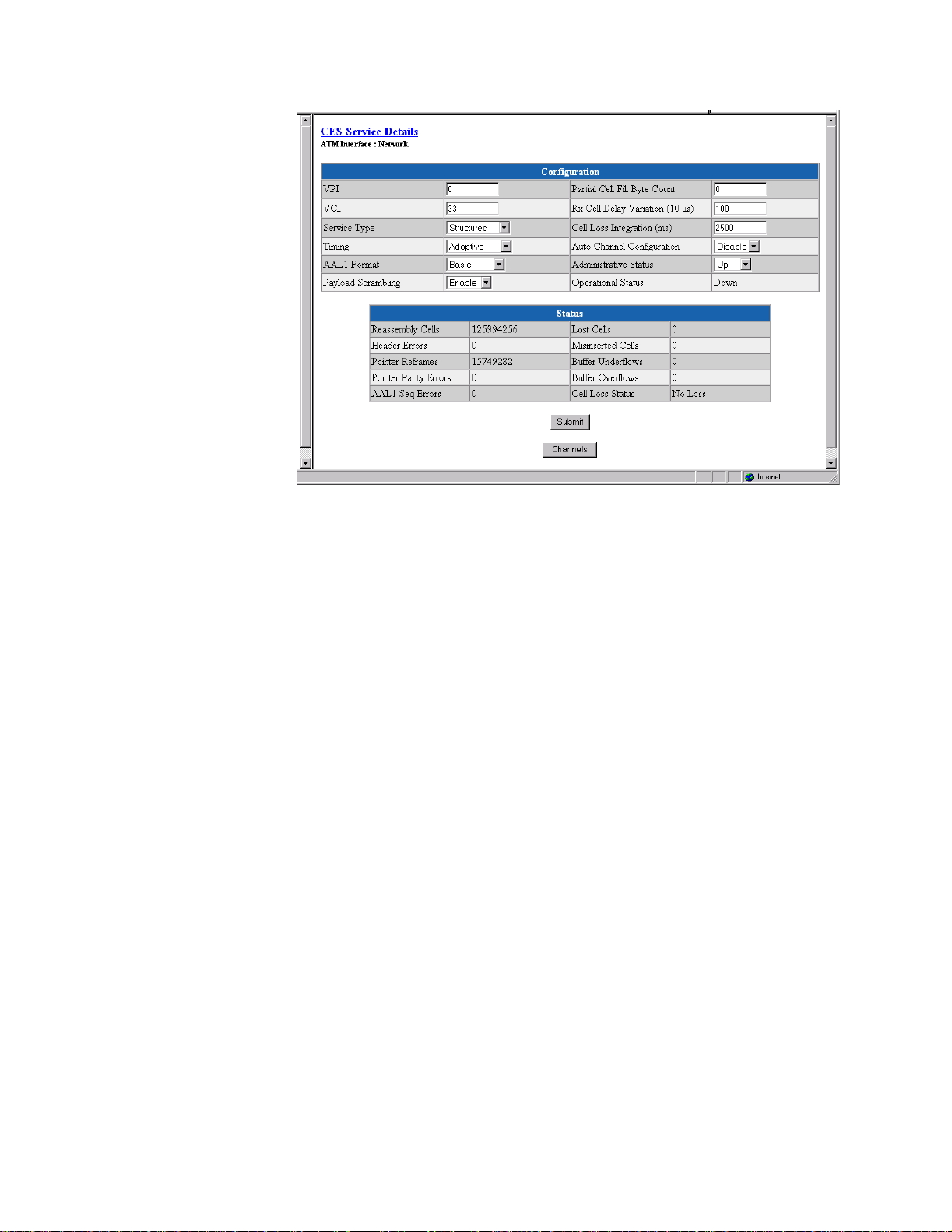
Figure 3.43
CES Service Deta ils Screen
From this screen, you can access and change the parameters listed below. The
new parameters are saved when you click on “Submit” and then perform a
Save and Restart.
VPI
VCI
Service Type
Timing
Determin es VPI us ed for t his CES Internet W orking Function (IWF). The
default is 0.
Determines VCI used for this CES IWF. The default is 33.
Determines if T1/E1 service is structured (Nx64 kbps with or without
signaling) or unstructured (2.048 or 1.544 Mbps raw data stream). You must
configure the Service Type to correspond with the desired CBR port framing
and Signaling in accordance with the table on page 3-58.
Determines the CES services clocking mode, which maps to the transmit
clock sou rce of the CBR interface an d Seria l interface (if con figured fo r a
CES ser vice). When “Ad aptiv e” tim ing is sele cted, the r eceive AAL 1 pa yload
buffer is monitored for predetermined threshold levels to control the
frequency of the i nterface c locks. Wh en the b uffer dep th exceed s the
predetermined upper threshold, the interface clock frequency is increased to
cause the buffer to drain more quickly. If the buffer depth falls below the
predetermined lower buffer threshold, the interface clock frequency is
decreased to cause the buffer to drain less quickly. Both lower and upper
threshold levels are used in conjunction with Cell Delay Variation to provide
hysteresis around threshold levels.
Values: Synchronous, Adaptive
Default: Adaptive
3-54 WANsuite 6450
Page 83

AAL1 Format
Specifies AAL1 for mat − B asic, E1Cas, Ds1SfCas, or Ds1EsfCas. This value
must be set in accordance with the table on page 3-58 for proper operation.
Payload Scrambling
Partial Cell Fill Byt e
Count
Rx Cell Delay
Variation (10 µs)
Cell Loss Integ ration
(ms)
AutoChannel
Configuration
The WANsuite 6450 scrambles/descrambles cell payload bytes at the physical
layer interface using an x43 + 1 polynomial. You may enable/disable the
scrambling function on the CES Service Details Screen. (Normal operation
will have Payload Scrambling enabled, which is the default.) (See Figure 3.43
on page 3-54.)
Sets the number of user octets per cell. Setting this parameter to 0 disables
Partial Cell Fill, and all cells are completely filled before being sent.
Maximum cell arrival jitter in 10-µs increments that the reassembly process
will tolerate in the cell stream without producing errors on the CBR service
interface. Default is 100 for a 1000-µs Cell Delay Variation (CDV).
Time in milliseconds for the cell loss integration period. If cells are
continuously lost during the specified period of time, Cell Loss Status is set to
“Loss.” Default is 2500 ms.
This feature applies only to circuit emulation of E1 CCS, E1 CAS, and Serial
CES services. When enabled, the WANsuite 6450 will automatically
configure the number of channels (N) allocated to the service according to the
negotiated SHDSL line rate. Channels are allocated starting with channel/time
slot 1 in consecutive order until N channels have been allocated to the service.
An emulated E1 CCS or Ser ial service may allocat e channe ls/time slo ts 1−31.
Refer to the table below that shows E1 Nx64 Basic Service Without Signaling
(E1 CCS ).
AAL5
SHDSL Data
Rate (kbps) N PCR
192 1 171 119.496 281
256 2 342 110.992 261
320 3 512 102.912 242
384 4 683 94.408 222
448 5 854 85.904 202
512 6 1024 77.824 183
576 7 1195 69.320 143
640 8 1366 60.816 143
704 9 1536 52.736 124
768 10 1707 44.232 104
832 11 1878 35.728 84
896 12 2048 27.648 65
960 13 2219 19.144 45
1024 14 2390 10.640 25
1088 15 2560 2.560 6
1152 15 2560 66.560 156
1216 16 2731 58.056 136
Bandwidth
kbps CPS
Web Server Interface 3-55
Page 84

AAL5
SHDSL Data
Rate (kbps) N PCR
1280 17 2902 49.552 116
1344 18 3072 41.472 97
1408 19 3243 32.968 77
1472 20 3414 24.464 57
1536 21 3584 16.384 38
1600 22 3755 71.880 18
1664 22 3755 71.880 169
1728 23 3926 63.376 149
1792 24 4096 55.296 130
1856 25 4267 46.792 110
1920 26 4438 38.288 90
1984 27 4608 30.208 71
2048 28 4779 21.704 51
2112 29 4950 13.200 31
2176 30 5120 5.120 12
2240 30 5120 69.120 163
2304 31 5291 60.616 142
2312 31 5291 68.616 161
Bandwidth
kbps CPS
An emul ated E1 C AS serv ice may allocate c hannels /time slots 1−15 and 17−
31 (refer to the table below). Channel/time slot 16, which carries the signaling
information, will not be allocated as a voice channel. Refer to the table below
for E1 Nx64 Basic Service With Signaling (E1 CAS).
AAL5
SHDSL Data
Rate (kbps) N PCR
192 1 182 114.832 270
256 2 352 106.752 251
320 3 534 93.584 220
384 4 704 85.504 201
448 5 886 72.336 170
512 6 1056 64.256 151
576 7 1238 51.088 120
640 8 1408 43.008 101
704 9 1590 29.840 70
768 10 1760 21.760 51
832 11 1942 8.592 20
896 12 2112 0.512 1
960 12 2112 64.512 152
1024 13 2294 51.344 121
1088 14 2464 43.264 102
1152 15 2646 30.096 70
1216 16 2816 22.016 51
1280 17 2998 8.848 20
Bandwidth
kbps CPS
3-56 WANsuite 6450
Page 85

AAL5
SHDSL Data
Rate (kbps) N PCR
1344 18 3168 0.768 1
1408 18 3168 64.768 152
1472 19 3350 51.600 121
1536 20 3520 43.520 102
1600 21 3702 30.352 71
1664 22 3872 22.272 52
1728 23 4054 9.104 21
1792 24 4224 1.024 2
1856 24 4224 65.024 153
1920 25 4406 51.856 122
1984 26 4576 43.776 103
2048 27 4758 30.608 72
2112 28 4928 22.528 53
2176 29 5110 9.360 22
2250 30 5280 1.280 3
2304 30 5280 65.280 153
2312 30 5280 73.280 172
Bandwidth
kbps CPS
Administrative Status
Operational Status
Reassembly Cells
Header Errors
Sets the Administrative Status of the CES IWF. “Up” indicates traffic flow is
enabled, and “Down” indicates traffic flow is disabled across the CES IWF.
NOTICE: To enable a new parameter, rather than saving and restarting, set the
Administrative Status to “Down,” and click on the “Submit” button at
the bottom of the screen. Then set the Administrative Status to “Up,”
and click on the “Submit” button once again.
Displays the Operational Status of the CES IWF. The state will be “Down” or
“Unknown” if the supporting CBR or ATM interface is down or unknown.
Status
Displays the number of cells received by the CES IWF. This number excludes
cells that have been discarded for any reason, including cells not used due to
their being misinserted or discarded while the reassembler was awaiting
synchronization.
Displays t he numb er of AAL 1 head er errors detected, including those th at
have been correcte d. Header errors include co rrectable and unco rrectabl e
CRCs and bad parity.
Pointer Reframes
Displays the number of events in which the AAL1 reassembler found a
Structured Data Pointer (SDT pointer) where it was not expected, making it
necessary to reacquire the pointer.
Web Server Interface 3-57
Page 86

Pointer Parity Errors
Displays t he numb er of eve nts in wh ich the AAL1 re assembler has de tected
an SDT pointer parity check failure.
AAL1 Seq Errors
Lost Cells
Misinserted Cells
Buffer Underflows
Buffer Overflows
Cell Loss Status
Displays the number of times the sequence number of an incoming AAL1
frame caus es a tra nsition from the “s ync” sta te to th e “out of sequence ” state.
Displays the number of cells detected as lost in the network prior to reaching
the destination CES IWF AAL1 layer processing. As an example, the number
of lost cells may be detected as a result of AAL1 sequence number
processing.
Displays the number of AAL1 sequence violations, which the AAL
Convergence Sublayer interprets as “misinserted cells.”
Displays the number of times the CES reassembly buffer underflows.
Displays the number of times the CES reassembly buffer overflows.
Displays “Loss” when cells are continuously lost during the specified Cell
Loss Integration Period. When a valid cell(s) is received, this condition is
cleared, and “No Loss” will be displayed.
Configuring the WANsuite 6450 for CES involves setting parameters not only
on the CES Service Details screen (Figure 3.43 on page 3-54), but also on the
CBR screen (Figure 3.13 on page 3-15); in some cases, the Serial screen
(Figure 3.17 on page 3-20); and the Channel Table Details screen (Figure 3.44
on page 3-59). The table below shows the settings required to maintain the
proper relationships among CBR framing, the CES Service Type, the CES
AAL1 format, and the Signaling.
CES Service
Description
Basic E1 (CCS) E1 CCS Structured Basic Disable
Serial E1 CCS Structured Basic Disable
Basic T1 (ESF) T1 ESF Structured Basic Disable
Basic T1 (D4) T1 D4 Structured Basic Disable
E1 w/Signaling (CAS) E1 CAS Structured E1Cas Enable*
T1 w/Signaling (ESF) T1 ESF Structured Ds1EsfCas Enable*
T1 w/Signaling (D4) T1 D4 Structured Ds1SfCas Enable*
Unstructured E1 E1 Unfram ed Unstructur ed Basic Disabl e
Unstructured Serial E1 Unframed Unstructured Basic Disable
Unstructured T1 T1 Unfram ed Unstructur ed Basic Disable
*Only channels allocated t o the CBR interface should have Signaling set to “Enable.” When confi gur ing the
Serial interface for CES service (see Serial CES Co nfigurati on as descr ibed on pa ge 3-61 ) , yo u must se t
the Signaling to “Disable for allocated chann els.”
CBR
Framing
CES Ser vice
Type
CES
AAL1
Format
Signaling
3-58 WANsuite 6450
Page 87

Channel Table Details Screen
To allocate Channels, or time slots, for CES services, click on the “Channels”
button at the bottom of the CES Service Detail s scre en to bring up the Channel
Table Details screen shown in Figure 3. 44.
Signaling
Figure 3.44
Channel Table Details Screen
The Channel Table Details screen lets you establish the Signaling, Service,
and Idle Pattern p arameter s for any available c hannel . The scre en param eters
are described below.
The unit can operate with Signaling enabled or disabled on channels. You
must set this value in accordance with the table above for proper operation.
Values: Disable, Enable
Default: Disable
Service
Idle Pattern
Specifies the service to which this channel is allocated. Service Index “0”
indicates the channel is not used or is idle. Service Index “4” indicates the
channel is allocated to the CBR interface. Service Index “5” indicates the
channel is allocated to the Serial interface.
Selects the idle pattern sent by the unit and lets the unit determine if the idle
pattern has been sent by the other end.
Values: 0−FF (Hex)
Default: 7F
NOTICE: Only channels with a non-zero Service parameter value are assembled
into ATM cells and transported across the SHDSL network. Similarly,
received ATM cells should only contain data for channels with a nonzero Service parameter value. When reassembling the data stream from
the received ATM cells, only the channels with a non-zero Service
parameter will be assigned data from the ATM cells. The non-active
channels with a Service parameter of “0” will be filled with an idle
pattern.
Web Server Interface 3-59
Page 88

The number of channels you can allocate for the CES service depends on the
available SHDSL bandwidth. The table below shows the maximum number of
channels you can allocate for CES for each possible SHDSL data rate. If the
required CES bandwidth exceeds the available SHDSL bandwidth, the unit
will not allow you to configure the CES service.
Maximum Number of CES Channels
SHDSL
Data Rate
(kbps)
192 2 2 2
256 3 3 3
320 4 4 4
384 5 5 5
448 6 6 6
512 7 6 6
576 7 7 8
640 8 8 8
704 9 9 9
768 10 10 10
832 11 11 11
896 12 12 12
960 13 12 12
1024 14 13 14
1088 15 14 14
1152 15 15 16
1216 16 16 16
1280 17 17 18
1344 18 18 18
1408 19 18 19
1472 20 19 20
1536 21 20 20
1600 22 21 22
1664 22 22 22
1728 23 23 24
1792 24 24 24
1856 25 24 24
1920 26 25 24
1984 27 26 24
2048 28 27 24
2112 29 28 24
2176 30 29 24
Structured Nx64
Basic Service
Structured Nx64
with E1 CAS Service
Structured Nx64
with T1 CAS Service
3-60 WANsuite 6450
Page 89

SHDSL
Data Rate
(kbps)
2240 30 30 24
2304 31 30 24
2312* 31 30 24
*This rate is proprietary to the GlobeSpan chipset and is re quired for unstructured E1 CES service.
Structured Nx64
Basic Service
Maximum Number of CES Channels
Structured Nx64
with E1 CAS Service
Structured Nx64
with T1 CAS Service
To allocat e a chan nel for the CBR interface, set the ch annel’ s “Rate”
parameter according to the table shown on page 3-58 and the S ervice
paramete r to the S ervice In dex for t he CBR i nterface (4). To allocate a
channel f or the Seri al Interfac e, refer to the paragraph s below.
Serial CES Configuration
The WANsuite 6450 has the capability to multi ple x/demultiplex the Serial
interface data stream with the CBR interface data stream. The multiple xing/
demultiplexing is external to the AAL1 SAR; the user controls it by designating
time slots for the C ES service on the CBR or Serial port. To configure the Serial
interface for CE S service, perform the follo wing steps:
1 On the Services screen (Figure 3.24 on page 3-27), click on the Service
Index associated with the Seria l interface (5). This will cause the unit to
display the Service Details screen for the Serial interface. On the Service
Details screen (Figu re 3.25 on pa ge 3-27), select “CES” from the “Type”
pull-down menu.
2 On the Serial screen (Figure 3.17 on page 3-20), configure the Serial
interface to your requirements. You must set the “Mode” parameter to
“DCE.” If the required time slots for the Serial interface are contiguous and
not already all ocat ed to the CBR port , yo u may allocat e t he req u ired
channels on the Serial scree n. I f you have not allocated channels for the
Serial interface on the Serial screen, use the Channel Table Details screen
(Step 3 below) to specify the channels for the Serial CES service.
3 On the Channel Table Details screen (Figure 3.44 on page 3-59), set the
desired channel’s “Ra te” para meter to “64K,” and the “Service” parameter
to the Service Index for the Serial interface (5).
Valid Channel Ranges for Serial and CBR Interfaces
The range of channels available to the Serial interface depends on the type of
CES service. The table below shows the range of channels available to the
Serial and CBR interfaces for each type of CES servi ce. The type of CES
Web Server Interface 3-61
Page 90

service and the SHDSL data rate shown in the table on page 3-60 limit the total
number of channels that can be allocated to the Serial interface.
Available Serial
CES Service Type
Description
Basic E1 (CCS) / Seri al 1
Basic T1 (E SF) 1
Basic T1 (D4) 1
E1 w/Signaling
(CAS)
T1 w/Signaling (ESF) 1
T1 w/Signaling (D4) 1
Unstructured E1/
Unstructured Serial
Unstructured T1 None*** 1
*Channel 16 (time slo t 6) can be us ed for th e Serial CES servi ce with out aff ec ting E1 signali ng. T he E1 sign alin g infor mati on is e x tra c te d f ro m th e
CBR interface data stream prior to multiplexing it with the Serial interface stream. Therefore, replacing channel 16 (time slot 16) with Serial
interface data will not affect the assembly or reassembly of the signaling data in the CES data stream.
**The signaling information in the channel is automatically extracted in this mode and assembled in the signaling substructure of the ATM
payload. Includin g channel 16 in the CBR interfa c e data stre am would dupl ic ate the dat a transmi tte d in the signa lin g substru c tu re and is
therefore not needed.
***An Unstructured T1 CES service is not compatibl e wit h a Serial interface CES service becaus e the Serial inter f ace does not support a 1.544
MHz clock r ate. However, you may use a Basic T1 CES service and alloca te all 24 channels to the Serial interface CES ser vice resulting in a
1.536 MHz clock rate.
Interface
Channel R a ng e
−31 1−31 Serial or CBR interfa ce channels may be any
−24 1−24 Serial or CBR interfa ce channels may be any
−24 1−24 Serial or CBR interfa ce channels may be any
1
−31* 1-15, 17-31 Serial interface channels may be any arbitrary set
−24 1−24 Serial or CBR interfa ce channels may be any
−24 1−24 Serial or CBR interfa ce channels may be any
0
−31 0−31 Multiplexing channels between the CBR and
Available CBR
Interface
Channel Range Comments
arbitrary set within the available channel range.
arbitrary set within the available channel range.
arbitrary set within the available channel range.
within the a vai lable cha nnel r ange. CBR inter fa ce
channels may not include Channel 16. **
arbitrary set within the available channel range.
arbitrary set within the available channel range.
Serial interface is not allowed for an unst ructured
service. All channels may be allocated to either
the Serial interface (Service parameter “5”), or the
CBR interf ace (Serv ice parameter “4”), or
disabled (Service parameter “0”).
−24 All channels must be allocated to t he CBR
interface (Service parameter “4”) or disabled
(Service parameter “0”).
HDLC/PPP Ser vice
This service has no configurable parameters.
Applications
The Applications screens describe configuration tables and statistics for
Layer 3 and above that do not map to a specific service or interface.
Service Aware
The Service Aware function recognizes IP traffic on the WAN and counts the
number of frames and bytes passed for a specific service based on filters by
VPI/VCI, by DLCI , by IP Address , and by IP Port. Each ro w of the Service
3-62 WANsuite 6450
Page 91

Aware table represents a specific set of filter parameters known as a “rule.”
Each rule is established through the Rule Config screen, which is accessed by
clicking the “Rule Details” button at the bottom of the Service Aware screen.
The Service Aware screen (Figure 3.45) provides a table showing these
filtered packet counts for up to 10 rules. This table indicates which Service
Aware filters are enabled or dis abled, and show s the specifi c VPI/VCI, DLCI,
IP Address, IP Ma sk, and IP Port by which the IP traffi c is filtered. In
addition, this table shows the Tx Alarm Threshold and the current Tx Alarm
status (if enabled) for each rule.
Figure 3.45
Service Aware Screen
The Servi ce Awar e screen p rovides a “Clear Alarms ” user-acti vated but tons:
Rule Details Screen
Access the Ru le Details scre en (Figure 3 .46), wher e you can establ ish Service
Aware parameters, by selecting the appropriate hyperlink from the “Index”
column in the above screen. To establish a rule, select the desired rule
configuration options, provide the appropriate filter information where
required, and click on the “Submit” button at the bottom of the screen.
Web Server Interface 3-63
Page 92

Figure 3.46
Rule Details Screen
The paragraphs below describe the rule configuration parameters and their
options.
Service
VPI
VCI
Filter By VPI/VCI
DLCI
Filter By DLCI
Selects the service to which the rule applies. Select from a pull-down menu
that lists available s ervices.
NOTICE: If you change the Service parameter, you must click on “Submit” to see
the appropriate DLCIs.
Selects the VPI to which the rule applies.
Selects the VCI to which the rule applies.
Enables or disables filtering of the IP traffic in accordance with the specified
VPI/VCI.
NOTICE: To use this filter, you must specify both the Service and VPI/VCI
parameters in the Rule Config screen.
Selects the DLCI to which the rule applies from a pull-down list of applicable
DLCIs.
Enables or disables filtering of the IP traffic by the DLCI specified in the
DLCI pull-down list.
NOTICE: To use this filter, you must specify both the Service and DLCI
IP Address
3-64 WANsuite 6450
Establishes the IP Address by which the rule will filter IP traffic (if enabled).
parameters in the rule configuration.
Page 93

IP Mask
Represents a range of IP Addresses defined so that only machines with IP
Addresses within the range defined by the mask are allowed to access an
Internet service. To mask a portion of the IP Address, replace it with the wild
card char acter “0” (zero). (Fo r exam ple, an I P Addre ss Filter o f 192.4 4.0.0
and an IP Mask Filter of 255.255.0.0 represent every computer on the Internet
with an IP Address beginning with 192.44.)
Filter By IP Address
IP Port
Filter By IP Port
Tx Alarm Threshold
Tx Alarm
Enables or disables filtering of the IP traffic by the IP Address specified in
the IP Address or IP Mask field.
Establishes the IP port by which the rule will filter IP traffic (if enabled).
Enables or disables filtering of the IP traffic by the IP port specified in the IP
Port field.
Specifies the threshold (in bps) for the Transmit Alarm on this rule.
Displays the cu rrent status of the Transm it Alarm.
Traffic Meter Statistics Screen
The Traffic Meter Statistics (Figure 3.47) screen displays the number of
frames and octets that have been counted in accordance with the Service
Aware “rule” that has been established for a Service. In addition, this screen
provides data rate performance information for the period of time specified in
the Period Index field (see below). Access this screen by clicking on the
appropriate “Statistics” hyperlink on the Service Aware screen.
Figure 3.47
Traffic Met er Statistics Screen
The Traffi c Meter S tatisti cs screen re ports T ransmit, Receive, and
Performance statistics on the following parameters:
• Tx Frames
Web Server Interface 3-65
Page 94

• Tx Octets
• Rx Frames
• Rx Octets
• Rate Peak – the peak data rate for the viewed period (see below)
• Rate Average – the average data rate for the viewed period (see below)
The Period Index field is used to define the period of time for which the
Traffic Meter statistics will be reported. It represents the 24-hour, 15-minute
buckets index. Selecting a period and then clicking the “Submit” button will
display th e traffic meter stat istics f or that peri od. Th e user-sel ectable op tions
are listed b elow.
Click on the “All Traffic Meter Intervals” button to see the screen shown below in
Figure 3.48.
SNMP
Figure 3.48
The unit detects and reports E1 network alarms and provides several options
for reporting them, one of which is SNMP traps. When a network alarm
occurs, the unit sends a trap message to as many as eight destinations on your
network. The unit will report each alarm by transmitting an SNMP “trap” to
each non-zero Trap IP Address. The SNMP Details screen (Figure 3.49) lets
you configure the SNMP parameters described below.
Figure 3.49
All Traffic Meter Stats (All Intervals) Screen
SNMP Details Screen
3-66 WANsuite 6450
Page 95

Read Community
Accepts a character string identifying the group authorized to perform read
operations. The default setting is “Public.”
Write Community
Trap Community
Trap IP Address
Trap Log
Accepts a character string identifying the group authorized to perform write
operations. The default setting is “Private.”
Accepts a character string, which is included in SNMP traps generated by the
unit. The default setting is “Public.”
Accepts the IP Address of a network device where alarm reporting traps are
to be sent.
A trap is a mecha nism that permits a device to send an alarm for certa in
network events to an SNMP management station. The Trap Log screen
(Figure 3.50) shows all generated traps.
The table shown in this screen lists each trap by its Index number, and
displays the type of error captured by the trap (Trap Number) and the date
and time that the trap was stored (Time Stamp).
Click the hyperlink at the top of the screen to display the latest trap
information in the table. To remove all trap information stored in memory,
click the “Delete All Traps” button at the bottom of the screen (not shown in
the figure below).
Top Talkers
Figure 3.50
Clicking on the “Top Talkers” link in the navigation tree displays a screen
(Figure 3.51) used to set the parameters for and initiate the generation of a list
of IP Addresses ranked in terms of the number of frames and octets they have
transmitted during a specified reporting period. This report allows MIS
managers to determine who is generating the most traffic on a WAN based on
IP Addresses.
Trap Log Screen
Web Server Interface 3-67
Page 96

Figure 3.51
Top Talkers Screen
To generate a Top Talkers report, enter the desired report size in the
appropriate field, and then click the “Submit” button.
Duration
Time Remaining
Requested Report Size
Report #
Establishes the amount of time (in seconds) for which the Top Talkers report
will capture IP traffic; typically this value is 900 seconds (15 minutes).
Establishes the amount of time (in seconds) for which the Top Talkers report
will capture IP traffic; typically this value is 900 (15 minutes). As soon as
you initiate generation of the report by pressing the “Submit” button, the
Duration value is copied over to the Time Remaining field. Click on the
hyperlink to see how much time is left before the report is completed.
Establishes how many IP Addresses will be reported as the “Top Talkers.”
NOTICE: While you may request any number, the unit is internally limited to a
maximum of 20.
As soon as the specified Duration for the report has elapsed, the screen will
refresh itself and the resulting report-specific information will be displayed in
the outlined box at the bottom of the screen. This report comprises elements
as defined in the following paragraphs.
This field displays a unique number used to identify the generated report. This
number is generated automatically, is incremented sequentially for each
report, and can be used by management stations for automatic polling (via the
ipadv2.mib).
Size
Displays the actual number of IP Addresses identified as Top Talkers in the
generated report. The maximum report size is 20.
Start Time
Displays the time at which the Top Talkers report was initiated (based on
System U p Time).
System Up Time
Displays the amount of time that the unit has been operational since it was
turned on or last reset.
3-68 WANsuite 6450
Page 97

IP Gateway
The Top Talkers table reports in descending order the IP Addresses that have
generated the most traffic during the requested report’s duration. For each IP
Address listed, the report displays the number of Rx frames, Rx octets, Tx
frames, and Tx octets that have been passed across it. In addition, the
Timestam p field in dicates th e time a t which a packet w as exam ined for the
specified IP Address.
The IP Gateway is a feature that allows routing of IP packets from one
network to another using static routes configuration and/or dynamic routing.
The IP Gateway uses Routing Information Protocol (RIP) 1 or RIP 2 or Open
Shortest Path First (OSPF) routing.
RIP 1 and RIP 2 are protocols that allow exchange of routing information
between two routers. With that information exchange, a router can build its
own routing tables that later can be used for “routing” IP packets.
OSPF is a shortest path first (SPF) or link-state protocol. OSPF is also an
internal gateway protocol (IGP) that distributes routing information between
routers in a single autonomous system (AS). OSPF chooses the least cost path
as the be st path.
While RIP is ideal for small- to medium-sized networks, OSPF is more
suitable for complex networks with a large number of routers. OSPF provides
equal cost multipath routing where packets to a single destination can be sent
via more than one interface simultaneously.
Figure 3.52
IP Gateway Details Screen
Web Server Interface 3-69
Page 98

RIP Parameters
RIP Enable
RIP Trust Neighbors
RIP Inter val
RIP Domain
OSPF Enable
OSPF Router ID
Globally enables RIP 1, RIP 2, or No RIP.
Values: Disable, Enable RIP1, Enable RIP2
Default: Enab le (RIP 2)
Globally enables the trusted neighbors feature. If there is a list of trusted
neighbors in an IP Gateway, only RIP packets coming from those trusted
neighbors will be used to build the internal routing table.
Values: Enable, Disable
Default: Enable
Interval for RIP packet to be sent. Default is 30 seconds.
Value representing the RIP domain. Default is 0.
OSPF Parameters
This Protocol is suitable for complex networks with a large number of routers.
If a large network is involved, OSPF may be the solution for the user.
Values: Disable, Enable
Default: Disable
This 32-bit number assigned to each router running the OSPF protocol
uniquely identifies the router within an autonomous system. Each router
requires a unique router ID. Default is the LAN IP Address of the unit.
The IP Ga teway scr een pr ovides the followin g user-act ivated b uttons:
Button Function
RIP Parameters
Static Routes Ta ble Displays static routes and dynamic route s information.
Static ARP Table Displays static ARP information.
Trusted Neighbors Displays trusted neighbors information.
OSPF Para meters
Area Table Displays area information.
Virtual Link Table Displays virtual link information.
Submit Submits to the unit information specific to IP Gateway.
Circuit Table Lets you access to c ircuit-related information/ope ration.
Circuit Table Screen
Access this menu by clicking on the “Circuit Table” button at the bottom of the
IP Gateway menu. This screen shows the configured circuit. Endpoints that
begin with “P,” such as Px-Cy, are for ATM VPI x, VCI y. For example, P0C32 is VPI 0, VCI 32. Endpoints that begin with “S,” such as Sx-yy, are for
3-70 WANsuite 6450
Page 99

Frame Relay Service x, DLCI yy. For example, S5-45 is Service 5, DLCI 45.
Endpoints that begin with “I” suc h as Ix-y-z are FRF5 Interworking Frame
Relay endpoints for VPI x, VCI y, DLCI z. For example I0-87-45 would be
FRF5 Interworking endpoint for VPI 0, VCI 87, DLCI 45.
Figure 3.53
Circuit Table Screen
To configure a new circuit, click on "Add New."
Circuit Details Screen
Access this menu (Figure 3.54) by clicking on the appropriate numbered link
under the “Index” column on the Circuit Table screen.
NOTICE: A “Submit” on this screen will activate a newly created circuit. It is not
necessary to perform a “Save and Restart” for the circuit to take effect.
Figure 3.54
Circuit Details Screen
Endpoint
Endpoint name. By default, the first circuit is always the LAN circuit. WAN
circuit endpoint names are taken from the VPI/VCI number. For example,
VPI 0/VCI 32 will have “P0-C32” for an endpoint name. The pull-down
menu will display a list of VPI/VCIs actually configured. A given circuit will
Web Server Interface 3-71
Page 100

receive/transmit data on the VPI/VCI combination corresponding to its
endpoint name.
IP Address
IP Mask
Max Transmit Unit
Cost
RIP Status
Multicast Status
OSPF Status
IP Address of the circuit.
IP Mask of the ci rcuit.
Maximum transmit unit this circuit will send at any one time.
Represents the relative time of treatment of an IP packet. This value is used
when there are mu ltiple rout es to th e same d estination . When t wo or more
routes ar e available, the one with the lowest circuit co st is sel ected. An ATM
circuit should have a higher value than a LAN circuit.
Indicates whether or not RIP is enabled on this circuit.
Values: Disable, Listen and Talk, Talk Only, Listen Only
Default: Listen and Talk
Indicates whether or not Multicast is enabled on this circuit.
Values: Enable, Disable
Default: Enable
Indicates w hether o r not OS PF is en abled on this circ uit.
Values: Enable, Disable
Default: Disable
OSPF Area
OSPF LSA Timer
OSPF LSU Delay
OSPF Router Priority
OSPF Hello Interval
Represent s the area that thi s circuit i s part o f.
Determines how often the Link State Acknowledgment (LSA) packet is sent.
Values: 1−3600
Default: 5
The estimated number of seconds it takes to transmit a Link State Update
(LSU) packet over this circuit interface.
Values: 1−3600
Default: 1
This 8-bit unsigned integer ranges from 1 to 255 and assigns priority to one of
two routers attached to the same network; without an assigned priority, both
routers attempt to become the designated router.
Values: 1−255
Default: 1
The time in seconds between the Hello packets that a router sends on a
circuit. This value is also advertised in the router’s Hello packets and must be
identical for all routers on the same network. The smaller the Hello Interval,
the sooner topological changes are detected (but then more traffic is created).
Values: 1−65535
Default: 10
3-72 WANsuite 6450
 Loading...