

Page 1

S Lite
Serial Data Loopback Device
34-00297.2
June 1999
D
S Lite
S1
7
4
3
2
1
L S
D
D
D
S1
S 1
S 2
.4 L
S 3
.21
S 4
30
S
.3
S -
S232
SD
D D
L L
Page 2

ii
Copyright Notice
Trademarks
EU Declaration of Conformity
Copyright © 1999 Verilink Corporation. All rights reserved.
This document does not create any express or implied warranty about Verilink or about
its products or services. Verilink’s sole warranty is contained in its product warranty.
The end-user documentation is shipped with Verilink’s products and constitutes the
sole specifications referred to in the product warranty. Verilink has made reasonable
efforts to verify that the information contained herein is accurate, but Verilink assumes
no responsibility for its use or for any infringement of patents or other rights of third
parties that may result. The customer is solely responsible for verifying the suitability
of Verilink’s products for its use. Specifications are subject to change without notice.
Manual reorder # 34- 00297
nd
Edition, June 1999
2
Verilink and the Verilink logo are registered trademarks of Verilink Corporation. S Lite
is a trademark of Verilink Corporation. All other trademarks or registered trademarks
are the property of their respective owners.
Model Number: S Lite
Manufacturer’s Name: Verilink Corporation.
Manufacturer’s Address: 127 Jetplex Circle
Telephone: (256) 772-3770
Facsimile: (256) 774-2277
The before mentioned product complies with the following EU directive:
89/ 336/EEC, “Council Directive of 3 May 1989 on the approximation of the laws of
Member States relating to electromagnetic compatibility”
The compliance of the above mentioned products with the Directives and with the
following essential requirements is hereby confirmed:
Emissions Immunity Safety
EN 55022, Class
A, 1995
The technical files and other documentation are on file with Mr. Ron Hillis,
Certification Manager.
As the manufacturer we declare under our sole responsibility that the above mentioned
products comply with the above named directives.
Madison, Alabama 35758
USA
EN 50082-1, 1992 EN 60950: 1992/A1 + A2: 1993 /
A3: 1995/A4: 1997
Ron Hillis,
Certification Manager, Verilink Corporation.
Madison Alabama, 27 May 1999
Place and Date
Page 3

iii
Warran ty
Customer Service
Returning Products
Safety Precautions
Verilink's product warranty covers repair or replacement of all equipment under
normal use for a five-year period from date of shipment. Replacement products may be
new or reconditioned. Any replaced or repaired product or part has a ninety (90) day
warranty or the remainder of the initial warranty period, whichever is longer. Our
in-house Repair Center services on a standard 10-workday-turnaround basis.
Verilink offers the following services:
✦
System Engineers at regional sales offices for network design and planning assistance
(800) 837-4546
✦
Technical Assistance Center for free 24×7 telephone support during installation,
maintenance, and troubleshooting at (800) 285 -2755 and support@verilink.com
✦
Return Materials Authorization (RMA) (800) 926 -0085, ext. 2282
✦
Maintenance contracts and leasing plans (800) 837- 4546, ext. 206
✦
Technical Training on network concepts and Verilink products at (800) 837-4546,
ext. 346 and training@verilink.com
✦
Web site at www.verilink.com
✦
FAX-On-Demand at (800) 957-5465
A product must be assigned a Return Materials Authorization (RMA) number before it
is sent to Verilink for repair. An RMA number is issued by Verilink Customer Service
at (800) 926 -0085, ext. 2282.
When handling this equipment, follow these basic safety precautions to reduce the risk
of electric shock and injury:
✦
Follow all warnings and instructions marked on the product and in the manual.
✦
Unplug the hardware from the wall outlet before cleaning. Do not use liquid cleaners
or aerosol cleaners. Use a slightly damp cloth for cleaning.
✦
Do not place this product on an unstable cart, stand, or table. It may fall, causing
serious damage to the product.
✦
This product should be operated only from the type of power source indicated on the
marking label and manual. If you are unsure of the type of power supply you are
using, consult your dealer or local power company.
✦
Do not allow anything to rest on the power cord. Do not locate this product where
the cord interferes with the free movement of people.
✦
Do not overload wall outlets and extension cords, as this can result in fire or electric
shock.
✦
Never push objects of any kind into the unit. They may touch dangerous voltage
points or short out parts that could result in fire or electric shock. Never spill liquid
of any kind on this equipment.
✦
Unplug the equipment from the wall outlet and refer servicing to qualified service
personnel under the following conditions:
✧
When the power supply cord or plug is damaged or frayed.
✧
If liquid has been spilled into the product.
✧
If the product has been exposed to rain or water.
✧
If the product has been dropped or if the housing has been damaged.
Page 4

iv
Page 5

Table of Contents
v
Copyright Notice . . . . . . . . . . . . . . . . . . ii
Trademarks . . . . . . . . . . . . . . . . . . . . . . . ii
EU Declaration of Conformity . . . . . . . ii
Warranty . . . . . . . . . . . . . . . . . . . . . . . . iii
Customer Service . . . . . . . . . . . . . . . . . iii
Returning Products . . . . . . . . . . . . . . . iii
Safety Precautions . . . . . . . . . . . . . . . . iii
About This Manual
What is a Reference Manual? . . . . . . . . 1
Where to go for Information . . . . . . . . . 1
Conventions . . . . . . . . . . . . . . . . . . . . . . 1
1 General
Introduction . . . . . . . . . . . . . . . . . . . . . . 3
Features . . . . . . . . . . . . . . . . . . . . . . . . . 3
Specifications . . . . . . . . . . . . . . . . . . . . . 4
Interfaces . . . . . . . . . . . . . . . . . . . . . 4
Performance Monitor . . . . . . . . . . . . 4
Loopbacks . . . . . . . . . . . . . . . . . . . . . 4
Configuration . . . . . . . . . . . . . . . . . . 4
Mechanical . . . . . . . . . . . . . . . . . . . . 4
Power Source . . . . . . . . . . . . . . . . . . 4
Industry Standards . . . . . . . . . . . . . . 4
Environmental . . . . . . . . . . . . . . . . . . 4
2 Installation and
Configuration
Introduction . . . . . . . . . . . . . . . . . . . . . . 5
Safety Summary . . . . . . . . . . . . . . . . . . . 5
Wallmount Installation . . . . . . . . . . . . . . 6
Using Adhesive Strips . . . . . . . . . 6
Using Screws . . . . . . . . . . . . . . . . 6
Connections . . . . . . . . . . . . . . . . . . . . . . 6
DCE and DTE Connections . . . . . . 6
Power . . . . . . . . . . . . . . . . . . . . . . . . 7
Configuration . . . . . . . . . . . . . . . . . . . . . 7
Configuration Switch S1 . . . . . . . . 7
V.54 Loop . . . . . . . . . . . . . . . . . . 7
Interface . . . . . . . . . . . . . . . . . . . . 7
Not Used . . . . . . . . . . . . . . . . . . . 7
Power Bypass . . . . . . . . . . . . . . . . . . . . . 8
3 Testing
Introduction . . . . . . . . . . . . . . . . . . . . . . 9
Indicators . . . . . . . . . . . . . . . . . . . . . . . . 9
Power . . . . . . . . . . . . . . . . . . . . . . . . 9
Loop Test . . . . . . . . . . . . . . . . . . . . . 9
Tx Data . . . . . . . . . . . . . . . . . . . . . . . 9
Rx Data . . . . . . . . . . . . . . . . . . . . . . . 9
V.54 Loop . . . . . . . . . . . . . . . . . . . . . . . . 9
Manual Loop . . . . . . . . . . . . . . . . . . 9
Detect Mode . . . . . . . . . . . . . . . . . . . 9
Page 6

vi
Page 7

BOUT
A
T
HIS
ANUAL
M
What is a Reference Manual?
Where to go for Information
Conventions
Convention Description
italics
underline Default settings are underlined.
This is a reference manual. It provides information about unit
installation, configuration, testing and troubleshooting on a
function-by-function basis. It is not a user’s guide containing
step-by-step procedures. This manual contains specific
information about a command, menu field, port, etc. Unless
otherwise noted, the information in this manual applies only to
the Verilink S Lite (also referred to as the unit.)
The chapters and appendices in this manual are arranged for
quick reference. It is not necessary to read previous chapters to
understand the subsequent chapters.
1 General - This chapter introduces the unit, lists the features, and
provides specifications.
2 Installation and Configuration - This chapter describes unit
installation, port and power connections, and switch settings.
3 Testing - This chapter describes the indicators, test switch, and
loopbacks.
The following table lists the conventions used throughout this
manual.
Notices call attention to important features or instructions.
Cautions alert you to personal safety risk, system damage, or data loss.
Warn i n gs alert you to the risk of severe personal injury.
Italics denote new terms or emphasis.
Page 8

2 A
BOUT THIS MANUAL
Page 9

1
ENERAL
G
Introduction
Features
The S Lite™ is a serial data loopback device with the ability to
go into remote loop for troubleshooting purposes. The S Lite
provides the capability to detect standard V.54 loop commands
from the local end to initiate loopbacks from the remote end and
to locally initiate remote loop. The customer can then determine
if a call to the local postal telegraph authorities is necessary.
The unit has a power bypass mode that allows data to pass
through the box when the unit is unpowered. The bypass mode
ceases when power is applied to the unit.
The S Lite supports X.21, V.35, EIA -530, and RS-232 interfaces
presented from DB-25 connectors. The interface and loop options
are chosen from DIP switches. Adapters are available to convert
the connectors to the desired pinout.
Space-saving design can be desktop or wall mounted
✦
90–256 VAC autoranging power supply
✦
DB-25 female DCE and DTE connectors
✦
LED status indicators
✦
DIP switch configurable
✦
Provides V.54 loopback detection on demand
✦
Power bypass relays on serial data loopback device to maintain
✦
service to the customer if the the serial data loopback device
loses power. Automatically terminates bypass mode when power
is restored to unit.
Page 10

4 C
HAPTER
1: G
Specifications
ENERAL
Interfaces
Performance
Monitor
Loopbacks
Configuration
Mechanical
Power
Source
Industry
Standards
Environmental
DCE: DB-25, female
DTE: DB-25, female
LED indicators: Power, Loopback Active, Tx Data,
and Rx Data
Remotely Initiated: via standard V.54 commands
Locally Initiated: via DIP switch
Loopback Control: 1 position
Interface Control: 4 positions
Mounting: desktop or wallmount
Dimensions: 1.25" H, 3.5" W, 5.75" D
Weight: 1 pound
External: Input: 90– 256 VAC autoranging
Output: 9 VDC
Low Voltage Directive 73 /23/EEC
EMC Directive 89/336/EEC
Operating Temp: 0° to 50°C(32° to 122°F)
Storage Temp: −20° to 70°C(−4° to 158°F)
Humidity: 95% maximum (non -condensing)
Page 11

NSTALLATION AND
I
2
Introduction
Safety Summary
Unpacking
and
Inspection
ONFIGURATION
C
This chapter contains information and instructions required to
prepare the Verilink S Lite for use. Included are initial inspection
procedures, mounting instructions, configuration guidelines,
connection and powering information.
This manual contains information and warnings that must be
followed to ensure safe operation and retain the equipment in a
safe condition.
This WARNING sign denotes a potential hazard to the
operator. It calls attention to a procedure or practice that, if
not correctly performed or adhered to, could result in injury or loss
of life. Do not proceed beyond a WARNING sign until the indicated
conditions are fully understood and met.
This unit is carefully packaged to prevent damage in shipment.
Upon receipt, inspect the shipping container for damage. If the
shipping container or cushioning material is damaged, notify the
carrier immediately and make a notation on the delivery receipt
that the container was damaged (if possible, obtain the signature
and name of the person making delivery). Retain the packaging
material until verifying the contents of the shipment are complete
and the unit has been checked both mechanically and electrically.
Supplied
Materials
If the contents of the shipment are incomplete or, if there is
mechanical damage or defect, notify Verilink. If the shipping
container is also damaged, or the cushioning material shows
signs of stress, notify the carrier of the damage as well as
Verilink. Keep the shipping materials for the carrier’s inspection.
Verilink will arrange for repair or replacement without waiting
for claim settlement.
The S Lite is shipped from the factory with the following
standard equipment.
external AC power supply
✦
reference manual or CD
✦
adapter cables (if applicable, based on unit or version ordered)
✦
adhesive strips
✦
Page 12

6 C
HAPTER
Wallmount Installation
NSTALLATION AND CONFIGURATION
2: I
Using Adhesive Strips
1 Select a place close to an AC outlet with clearance for the signal
and power cables. The indicators and switches should be easily
accessible.
2 Verify the mounting surface is clean.
3 Cut the adhesive strip to the desired length and affix the backing
of one piece to the underside of the unit.
4 Attach the other adhesive strip to the piece on the underside of
the unit.
5 Remove the backing to expose the sticky surface.
6 Press the underside of the unit firmly against the selected place.
Using Screws
1 Select a place close to an AC outlet with clearance for the signal
and power cables. The indicators and switches should be easily
accessible.
2 Vertically place two #6 screws 3-13⁄32 inches apart at the
selected place. Leave the screws out about an eighth of an inch.
3 Place the upright unit over the screws until the holes engage and
slide the unit down until it locks.
Connections
DCE and DTE
Connections
The S Lite has female DB-25 connectors for the DCE and DTE
interfaces, and a power connector. The following paragraphs
describe these connections.
Table 2-1 shows the pinout for the DCE and DTE connectors.
Table 2-1 DCE and DTE Connector Pinout
Pin DCE and DTE Pin DCE and DTE
1 Shield Ground 14 TXD B
2 TXD A 15 TXC A
3 RXD A 16 RXD B
4RTS A 17 RXC A
5CTS A 18 LL
6DSR A 19 RTS B
7 Signal Ground 20 DTR A
8DCD A 21 RL
9RXC B 22 DSR B
10 DCD B 23 DTR B
11 SCTE B 24 SCTE A
12 TXC B 25 TM
13 CTS B
Page 13

Configuration 7
Power
Configuration
Configuration
Switch S1
Plug the connector from the power supply into the unit. Plug the
transformer into an appropriate outlet. This applies power to the
unit. Units require an AC IEC interconnect power cord.
This section
describes the
configuration
of the S Lite.
This unit is
configured
using DIP
V.54 Manual Loop
B
X.21 Selected
EIA-530 Selected
V.35 Selected
RS-232 Selected
not used
not used
switches S1.
Refer to
Figure 2-1 for
switch
S1
314
2
5867
A
locations.
not used
not used
not selected
not selected
not selected
not selected
V.54 Loop Detect
Figure 2-1 Verilink S Lite Configuration Switches
This switch provides the following configuration parameters.
V.54 Loop
Position 1 is used to set the unit to detect remotely initiated V.54
loop commands (A) or manually initiate a loopback (B). See page
9 for more information. The default is V.54 Loop Detect (A)
.
not used
not used
Interface
Positions 2, 3, 4, and 5 are used to select an interface (see
Figure 2-1).
Only one of these switches can be in position B at a time.
Disconnect the DCE and DTE cables from the unit before
selecting an interface.
Not Used
Positions 6, 7, and 8 are not used.
Page 14

8 C
HAPTER
NSTALLATION AND CONFIGURATION
2: I
Power Bypass
The S Lite can operate in a power bypass mode where the S Lite
passes the signal from the network to the equipment and vice
versa whether in a powered state or not.
The power bypass mode uses relays that switch the network and
equipment connections. When the unit is powered and stable, the
relays have the network and equipment connections switched into
the S Lite’s internal circuitry. When the unit loses power, the
relays switch the network connection to a direct connection path
to the equipment connection. When power is reestablished the
relays switch the network and equipment connections back into
the S Lite’s internal circuitry.
Page 15
3
ESTING
T
Introduction
Indicators
Power This green indicator shows that power is applied to the unit.
Loop Test This indicator show the loop status of the unit. Amber indicates
Tx Data This green indicator shows the unit is transmitting data.
Rx Data This green indicator shows the unit is receiving data.
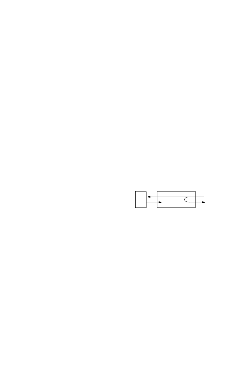
V.54 Loop
Manual Loop This loop is activated by
This chapter describes the diagnostic and test features of the
Verilink S Lite. The unit is controlled manually using DIP
switches (the DIP switches are discussed on page 7).
The unit indicators show power, loop status, and data activity.
the unit is in loop mode. When the indicator is Off, the unit is
not in loopback.
This section describes loops that can be initiated on the S Lite.
setting DIP switch S1-1 to
the B position. This loop is
unidirectional and returns
the DCE receive data to the
DCE transmit data. The loop functions as shown in Figure 3-1.
DTE
Figure 3-1 V.54 Loop
S Lite
DCE
Detect Mode The unit is RDL compatible.
This loop is activated by the receipt of the V.54 loop command.
This loop is unidirectional and returns the DCE receive data to
the DCE transmit data. The loop functions as shown in
Figure 3-1.
The loop up code is 2048 ± 100 bits of V.54 loop-up pattern.
When this is detected, the unit is looped. The loop down code is
8192 ± 100 bits of V.54 loop-down pattern followed by 64 ones.
Page 16

10 C
HAPTER
3: T
ESTING
 Loading...