

Page 1

Verilink SCM
User Manual
September 1999
P/N 880-503300-001-C1
Page 2

Copyright Notice
Trademarks
FCC Requirements
Copyright 1999 Verilink Corporation. All rights reserved.
This document does not cr eate any expr ess or i mplie d war r anty abo ut Ve r il ink o r ab out
its products or services. Verilink’s sole warranty is contained in its product warranty.
The end-user documentation is shipped with Verilink’s products and constitutes the
sole specifications referred to in the product warranty. Verilink has made reasonable
efforts to verify that the information contained herein is accurate, but Verilink assumes
no responsibility for its use or for any infringement of patents or other rights of third
parties that may r esult. T he customer is sole ly resp onsible fo r veri fying the suitabil ity of
Verilink’s products for its use. Specifications are subject to change without notice.
Verilink is a registered trademark of Verilink Corporation. Access System 2000,
WANscope, VeriStats, and FrameStart are trademarks of Verilink Corporation.
Any named products herein are trademarks of their respective companies.
This equipment has been tested and found to comply within the limits for a Class A
digital device pursuant to Part 15 of the Federal Commun ications Commission (FCC)
rules. These limits are designed to provide protection against harmful interference in a
commercial environment.
This equipment generates, uses, and can radiate radio frequency energy and, if not
installed and used in accordance with the user manual, can cause harmful interference
to radio communications.
There is no guarantee that interference will not occur in a particular installation. If this
equipment causes harmful interference to radio or television reception—which can be
determined by turning the equipment off and on—try to correct the interference by one
or more of the following measures:
• Reorient or relocate the receiving antenna.
• Increase the separation between the equipment and receiver.
• Connect the equipment into an outlet on a circuit different from that to which the
receiver is connected.
• Consult the dealer or an experienced radio/TV technician for help.
This equipment complies with Part 68 of the FCC Rules. On the rear, side or bottom of
the unit is a label that contains the FCC registration number and other information. If
requested, provide this information to the telephone company.
• All direct connections to the network lines must be made using standard plugs
and jacks (compliant wi th Part 68). The following tables list the applicable
registration jack universal order codes (USOCs), facility interface codes (FICs), and
service order codes (SOCs). These are required to order service from the telco.
For T1 interfaces:
Port ID REN/SO C FIC USOC
1.544 Mbit/s SF
1.544 Mbit/s SF, B8ZS
1.544 Mbit/s ANSI ESF
1.544 Mbit/s ANSI ESF, B8ZS
For DDS interfaces:
Port ID REN/SO C FIC USOC
56 kbit/s
64 kbit/s
• If the unit appears to be malfunctioning, inform the telco and disconnect it from
the network lines until the source of trouble is determined to be your equipment
or the telephone line . If your equipment needs repair, it should not be
reconnected until it is repaired.
• The unit has been designed to prevent harm to the network. If the telephone
company finds that the equipment is exceeding tolerable parameters, it can
temporarily disconnect service. In this case, the telephone company will provide
you advance notice if possible.
ii
Verilink Module SCM Manual
6.0N 04DU9 -BN
6.0N 04DU5 -56
04DU9 -DN
04DU9 -1KN
04DU9 -1SN
04DU5 - 64
RJ-48C jack
RJ-48S jack
Page 3

Lithium Battery
• If the telephone company alters its equipment in a manner that can affect the use
of this device, it must give you warning so that you have the opportunity to
maintain uninterrupted service. You will be advised of your right to file a
complaint with the FCC.
• No customer is authorized to repair this equipment, regardless of warranty
status. All repair s must be performe d by Ve ril i nk or an auth or ized age nt . It is the
responsibility of users requiring service to report the need for service to Verilink
or to one of our authorized agents.
The lithium battery referred to in the following notices is contained inside the clock
chip.
English
Français
DANGER!
The battery can ex plo de i f inco rre ct ly rep lac ed! Repl ace on ly with th e sam e or equi valent type recommen ded by the manufacturer. Di sp os e of used batteries according
to the manufacturer’s instructions.
DANGER!
To avoid electrical shock in case of f ailur e , th e power supply must be installed by a
professional installer. The terminal labeled with the ground symbol ( ) on the
power supply must be connected to a permanent earth ground.
CAUTION!
Interconnecting circuits must comply with the requirements of
EN60950:1992/A4:1997 Section 6.2 for telecommunications network voltages (TNV)
circuits.
ATTENTION!
Une explosion peut se produire si la batterie est remplacée d’ une façon incorrecte!
Remplacez-la seulement avec le même modêle de batterie ou un modèle équivalent
selon les recommendations de manufacture. Disposez de les batteries usées selon le s
instructions de manufacture.
ATTENTION!
Pour éviter choc électrique en cas de insuccès, la provision de pouvoir doit êtré
installé par un installeur professionnel. Le terminal de la provision de pouvoir, marqué du symbol de terre, ( ) doit connecté à un circuit de terre permanent.
PRUDENT!
Les circuit s doi vent êtré i nter conn ectés de mani ère à ce qu e l’ é quipe ment contin ue a
êtré en agrément avec “EN60950:1992/A4:1997, Section 6.2, pour les circuits de
voltage de liaisons d’ échanges (réseau) par les télécommunications (TNV), ” après les
connections de circuits.
Españole
ATTENCION!
La bateria puede explota r si se reem plaza incorr ec tamente. Reemplace la b a t er ia con
el mismo tipo de bateria ó una equivalente recomendada por el manufacturero. Disponga de las baterias de acuerdo con las instrucciones del manufacturero.
ATTENCION!
Para evitar contacto con circuitos que electrocutan, la fuente de alimentación debe
ser instalada por un técnico profesional. La terminal de la fuente de alimentación
marcada con el símbolo de tierra ( ) debe ser conectada a un circuito de vuelta por
tierra permanente.
PELIGRO!
Circuitos que se interconectan a la red de telecomunicaciones deben hacerse de tal
manera que cumplan con los requisitos estipulados en las especificaciones
“EN60950:1992/ A4:1997 , Secció n 6.2, pa ra los vo ltages de c ircuit os interco nnectado s
a la Red de Telecomunicaciones (TNV),” despues de terminar las connecciones entre
los circuitos.
Verilink SCM User Manual
iii
Page 4

Deutsch
VORSICHT!
Explosionsgefahr bei unsachgemäßem Ersetzen der Batterie! Batterie gleichen Typs
und gleich er Qualität benutzen, wie vom Her s t eller empf ohlen. Ents orgung der Batterie nach Anweisung des Herstellers!
VORSICHT, GEFAHR!
Um keinen Schlag zu erhalten beim Versagen der electrische n Anl a ge, muss der Stromanschluss von ei nem Elektriker vorge nommen werden. Der el ektrische Pol, verse hen mit dem Erdsymbol ( ) muss am Stromanschluss permanent geerdet sein.
VORSICHT!
Schaltungen, die in den Geräten zusammengeschaltet sind, müssen weiterhin den
Vorschriften EN60950:1992/A4:1997, Absatz 6.2 für Telecommunications Netz
Spannung (TNV) Schaltkreize entsprechen.
Canadian
Requirements
Safety Precautions
This digital apparatus does not exceed the Class A limits for radio noise emissions from
digital apparatus set out in the Radio Interference Regulations of the Canadian
Department of Communications.
Le présent appareil numérique n’émet pas de bruits radioélectriques dépassant les
limites applicabl es aux appareils numériques (de la class A) prescrites dans le
Règlement sur le brouill age radi oélect riq ue éd icté par le mi nist ère des Communi ca tion s
du Canada.
The Industry Canada label indentifies CS-03 certified equipment. This certification
means that the equipment meets certain telecommunications network protective,
operational and safety requirements. Industry Canada does not guarantee the
equipment will operate to the user’s satisfaction.
Before installing this equipment, users should ensure that it is permissible to be
connected to the facilities of the local telecommunications company. The equipment
must also be installed using an acceptable method of connection. In some cases, the
company’s inside wiring associated with a single line individual service may be extended
by means of a certified connector assembly (telephone extension cord). The customer
should be aware that compliance with the above conditions may not prevent
degradation of service in some situations.
Repairs to certifi ed equipmen t should be made by a n authoriz ed Canad ian maint enance
facility designated by the supplier. Any repairs or alterations made by the user to this
equipment, or equipment malfunctions, may give the telecommunications company
cause to request the user to disconnect the equipment.
Users should ensure for their own protection that the electrical ground connections of
the power utility, telephone lines and internal metallic water pipe system, if present, are
connected together. This precaution may be particularly important in rural areas.
Caution: Users should not attempt to make such connections themselves, but should
contact the appropriate electric inspection authority, or electrician, as appropriate.
This equipment is intended to be installed only in a Restricted Access Location that
meets the following criteria:
• Access can only be gained by service personnel or users who have been instructed
about the reasons for the restrictions applied to the location and about any
precautions that must be taken.
• Access can only be gained through the use of a lock and key or other means of
security, and is controlled by the authority responsible for the location.
When handling this equipment, follow these basic safety precautions to reduce the risk
of electric shock an d in ju ry :
• Follow all warnings and instructions marked on the product and in the manual.
• Unplug the hardware from the wall outlet before cleaning. Do not use liquid
cleaners or aerosol cleaners. Use a cloth slightly dampened with water.
• Do not place this product on an unstable cart, stand, or table. It may fall, causing
serious damage to the product.
• Slots and openings in the shelves are provided for ventilation to protect them
from overheating. These openings must not be blocked or covered. Never place
this product near a radiator or heat register.
iv
Verilink Module SCM Manual
Page 5

Product Warranty
Customer Service
Publications Staff
• This product should be operated only from the type of power source indicated on
the marking label and manual. If you are unsure of the type of power supply you
are using, consult your dealer or local power company.
• Do not allow anything to rest on the power cord. Do not locate this product where
the cord will interfere with the free movement of people.
• Do not overload wall outlets and extension cords, as this can result in fire or
electric shock.
• Never push objects of any kind into the shelves. They may touch dangerous
voltage points or short out parts that could result in fire or electric shock. Never
spill liquid of any kind on this equipment.
• Unplug the equipment from the wall outlet and refer servicing to qualified service
personnel under the following conditions:
• When the power supply cord or plug is damaged or frayed.
• If liquid has been spilled into the product.
• If the product has been exposed to rain or water.
• If the product has been dropped or if the cabinet has been damaged.
Verilink’s product warranty covers repair or replacement of all equipment under normal
use for a five-year period from date of shipment. Replacement products may be new or
reconditioned. Any replaced or repaired product or part has a ninety (90) day warranty
or the remainder of the initial warranty period, whichever is longer. Our in-house Repair
Center services returns within ten working days.
Verilink offers the following services:
• System Engineers at regional sales office s for network design and planning
assistance (800) 837- 4546
• Technical Assistance Center for free 24x7 telephone support during installation,
maintenance, and troubleshooting (800) 285-2755 and support@verilink.com
• To return a product, it must be assigned a Return Materials Authorization (RMA)
number before sending it to Veril i nk for repa ir (800) 92 6- 0085 , ext. 228 2
• Maintenance contracts and leasing plans (800) 837-4546
• Technical Training on network concepts and Verilink products (800) 282-2755
and training@verilink.com
• Web site (www.verilink.com)
This manual was written and illustrated by Marie Metivier.
Contributing Writers and Editors: Steve Rider, Theresa Lau, and Barbara Termaat.
Verilink SCM User Manual
v
Page 6

vi
Verilink Module SCM Manual
Page 7

Table of Contents
SCM Overview
About this Manual ........................................................................................ 1-1
Applications........................................................................................................ 1 -1
Network Node Management ......................................................................... 1-2
Features Summary .............................................................................................. 1-2
Features Detail.................................................................................................... 1-2
Automatic Discovery and Restoral.............................................................. 1-2
SCM as a Gateway......................................................................................... 1-3
Circuit Manager Database ........................................................................... 1-3
Shelf Compatibility ..................................................................................... 1-4
Advanced Programmable Architecture......................................................... 1-4
Advanced Communication Protocol............................................................. 1-4
System Hardware................................................................................................ 1-4
SCM Front Module ........................................................................................ 1-4
NIM 3000 Network Interface Module............................................................ 1-5
Craft Interface .................................................................................................... 1-6
Craft Interface Port....................................................................................... 1-7
SNMP Clients....................................................................................................... 1-7
Verilink Enterprise MIBs............................................................................... 1-8
Verilink Vendor Number .............................................................................. 1-8
Environmental Specifications............................................................................. 1-8
Related Verilink Documents ............................................................................... 1-9
.......................................................................................................... 1-1
SCM Quick Set-Up
Installation ................................................................................................... 2-1
Craft Interface.............................................................................................. 2-1
Administration Menu.................................................................................... 2-1
Configuring Local Modules .......................................................................... 2-1
Circuit Build ................................................................................................. 2-1
Remote Configuration ...... ... ......................................................................... 2-2
Enable Alarms............................................................................................... 2-2
Craft Interface
Accessing Remote Nodes.............................................................................. 3-1
Use SCM Craft Interface................................................................................ 3-1
Firmware Varia tions ... ... ............................................................................... 3-1
Starting a Session ........................................................................... .................... 3-1
Using Telnet ........ ... ... ...................... ...................... ...................................... 3-2
The Main Menu ................................................................................................... 3-5
Menu Heading............................................................................................... 3-5
..................................................................................................... 2-1
.......................................................................................................... 3-1
Verilink SCM v
Page 8

Shelf/Slot Map.............................................................................................. 3-6
Module Key................................................................................................... 3-6
Command Line Prompt........ ... ......................................... ............................. 3-7
Selecting a Module ....................................................................................... 3-7
Main Menu Options............................................................................................. 3-8
Administration ............................................................................................. 3-9
Configuration ............................................................................................... 3-9
Diagnostics................................................................................................. 3-10
Performance and Status ............................................................................. 3-11
Alarms ........................................................................................................ 3-12
Circuit Manager.......................................................................................... 3-14
Manufacturing Info..................................................................................... 3-15
Module-Specific Menu s............................................................................... 3-15
Administration Menu
............................................................................................... 4-1
Selecting the Administration Menu .................................................................... 4-1
Accessing Nodes................................................................................................. 4-4
Setup Requirements ..................................................................................... 4-4
Node Management Menu .............................................................................. 4-5
Deleting Nodes ............................................................................................. 4-8
Set Shelf Type............................ ... ......................................... ............................. 4-9
Using Passwords................................................................. ...................... .......... 4-9
Password Levels ......................................................................................... 4-10
Displaying Passwords................................................................................. 4-10
Changing Passwords................................................................................... 4-11
TheTCP/IP Configur a tion Men u........................................................................ 4-11
Ethernet and SLIP Parameters..................................................................... 4-12
Configuring Modem Parameters ....................................................................... 4-14
Setting Time and Date................................................................................ 4-16
Exiting the Administration Menu ............................................................... 4-16
Circuit Manager
........................................................................................................ 5-1
Cautions ....................................................................................................... 5-1
Modules Supported for Building Circuits..................................................... 5-1
Rules............................................................................................................. 5-1
Circuit Manager Functions.................................................................................. 5-3
Alarm Handling .......................... ... ... ........................................ .................... 5-3
Module Configuration Updates .................................................................... 5-3
Circuit Manager Menu......................................................................................... 5-3
Adding Circuits ............................................................................................ 5-5
Editing and Cloning New Circuits....................................................................... 5-7
Changing Name Clones New Circuit............................................................. 5-8
Setting Up a Cloned Circuit.......................................... ................................ 5-9
Downloading and Broadcasting Firmware
.............................................................. 6-1
Using the Administrat ion Men u in Downloads... ...................... .......................... 6-2
Different Command Op tions.. .... .................................................................. 6-3
vi Verilink SCM
Page 9

Firmware Options .........................................................................................6-4
Upgrading SCM Firmw a re....................................................................................6-5
Preview .........................................................................................................6-6
Upgrading SCM Flashb an k s........ ... ... ...................... .......................................6-6
Broadcasting Firm wa re.................................................... ....................................6-9
TABS Download for the IMUX......................................................................6-10
Broadcast Results............. ... ......................................... ...............................6-10
Securing the Download Fi le ............................ .... ........................................ 6-10
Checking the Result/Retrying Broadcast...................................................6-12
Card Retransmit..........................................................................................6-13
Switching over to the New Firmware ..........................................................6-13
Download Notes..........................................................................................6-15
Confirming the Firmware Upgrade .............................................................6-15
Verlink SCM
vii
Page 10

viii Verilink SCM
Page 11

Chapter
1
About this Manual
SCM Overview
This document describ es the Access System 3000 (AS3000) System
Controller Module, SCM, is the controller for Verilink’s high
bandwidth Integrated Access Device (IAD).
For information about specific applications that are managed by
the SCM, see the appropriate application manual.
This manual provides information specific to the SCM:
•
Chapter 1 contains features and general information.
•
Chapter 2 provides “SCM Quick Set-Up” information.
•
Chapter 3 illustrates the “Craft Interface”.
•
Chapter 4 explains the “Administration Menu”.
•
Chapter 5 covers the “Circuit Manager”.
•
Chapter 6 includes “Downloading and Broadcasting Firmware”.
Applications
Every AS3000 node must include one SCM module.
The SCM is a networked intelligent module that is devoted
exclusively to management tasks. It has no data-carrying t asks. The
SCM is IP-addressable and is the access point to an AS300 0
network.
The SCM contains an embedded Craft (ASCI I) inte rface that a llows a
system administrator to co ntrol, configure, administer, and
monitor application modules in the local node and in remote SCMmanaged nodes of an AS3000 network.
The SCM also has an embedded SNMP agent that acts as a host for
the optional Node Manager or any other SNMP-based network
manager. SNMP, Telnet and FTP protocols are supported through
Ethernet and SLIP connectors.
Verilink’s Node Manager is an optional graphical user interface
(GUI) application that runs under Windows 95. It can manage an
entire network containing AS2000 and AS3000 nodes. Node
Manager can access the SCM directly or use SNMP over ethernet or
SLIP.
Verilink SCM 1-1
Page 12

SCM Overview
Network Node Management
Features Summary
A major feature of the SCM is that a local S CM Craft interface
session can access up to 30 other nodes in an AS3000 network. You
can manage elements in those nodes as if each were in your local
node, through sessions that the Craft interface establishes to SCM
modules in the network. These sessions communicate via inband
management channels connecting a network of AS300 0 nodes.
Inband management channels can be config ured to use a p ortion of
the network circuit overhead between nodes.
The SCM is purely a management module. No network service or
end-user applicatio n equipment can be connected to it. SCM tasks
and features include:
•
Administrative functions
•
Configuration of all application modules in a network of local
and remote AS3000 nodes
•
Circuit management and bandwidth management—real- time
circuit building/ro uting support including dr op-and-insert and
bypass
Features Detail
Automatic Discovery and Restoral
•
Alarm management with up to four trap hosts
•
Performance monitoring and management
•
Diagnostics and troubleshooting
•
Security management using four levels of password access
protection
Major features of the SCM include:
When initially plugged into its node, the SCM automatically
“discovers” the elements in the node. In restoral mode, a new
application module that replaces a previously-configured like
module in the same slot is automatically reconfigured by the SCM
from the SCM database. This restoral process also detects
backplane circuits that included th e replaced or cleared module.
In restoral mode, an unco nfi gured module is downloaded with a
complete configuration from the SCM nodemaster database.
1-2 Verilink SCM
Page 13
SCM Overview
NOTE:
B
ecause the database resides in the SCM module, an SCM
moved to a differen t node without having its database first
cleared will reconfigure the new node. Take care not to cause
unintended configuration effects when swapping or moving
SCMs.
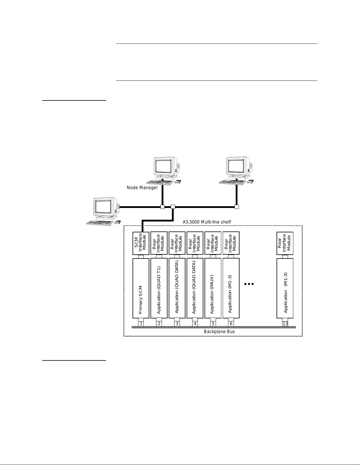
SCM as a Gateway
The SCM is responsible for managing all the slots within the node.
All communication between the SCM and the slots use the
backplane bus. Additionally, the SCM acts as a gateway for
management traffic passing between the slots and the optional
Node Manager software package.
Figure 1-1 Shelf with Mirrored Node Managers and SCMs
Node Manager
Ethernet
Node Manager
Node Manager Console
Circuit Manager Database
AS3000 Multi-line shelf
SCM
Rear
Module
Interface
Primary SCM
123456 13
Interface
Application (QUAD T1)
Module
Rear
Interface
Application (QUAD DATA)
Module
Rear
Module
Interface
Application (QUAD DATA)
Backplane Bus
Rear
Interface
Application (IMUX)
Module
Rear
Module
Interface
Application (M1-3)
Rear
Interface
Application (M1-3)
Module
The SCM module has a Circuit Manager database. This database
contains the configuration and circuit info rmation for the entire
node. The SCM maps T1 datastreams across the shelf backplane
and within AS3000 application modules.
Verilink SCM 1-3
Page 14

SCM Overview
Shelf Compatibility
Advanced Programmable Architecture
Advanced Communication Protocol
System Hardware
The SCM is compatible with the AS3000 plug-in modul ar shelf
system, the MLS 3000 and the QLS 3500. The SCM manages only
AS3000 applications. It can not replace an NCM, NCC, or SCC
module as a node contro ller for AS2000 products.
The SCM supports the downloading of firmware upgrades to the
application modules. The SCM can broadcast new firmware
revisions to multiple application modules in a shelf
simultaneously.
The SCM communicates with the AS3000 application modules using
Verilink’s proprietary Advanced Communication Protocol (ACP). It
can also use the standard TABS protocol to communicate with the
IMUX modul e .
The SCM assembly consis ts of a front module and a rear connector
module (NIM 3000), occupying a single shelf/slot position. The NIM
is installed first from the rear of the shelf. The SCM front module is
then installed from the front into the backplane. The NIM is always
installed first and removed last. The SCM front module is always
installed last and removed first.
For more information on Access System 3000 hardware, see the
manual AS3000: Th e Basics.
SCM Front Module
The SCM front panel provides LED indicators and management
ports. It is equipped with dual ejector levers to aid installation and
removal of the mo du le . Figure 1-2 illustrates the module front
panel.
Figure 1-2 SCM Front Panel
Primary Management port for direct connection to a PC running
Node Manager via RJ-45.
Craft interface port (6-pin RJ-11)
SCM
3000
TX
✳
RX
COL
✳✳
LOCAL
ACT
ALM
SYS
✳✳✳
PRI
MANAGEMENT
EXT
1-4 Verilink SCM
Page 15

SCM Overview
Front Panel LEDs
Management Ports
The SCM front panel provides six status LEDs:
TX
•
—Transmit. Flashes green whenever this SCM transmits a
packet to the Ethe rnet.
RX
•
—Receive. Flashes green whenever this SCM receives a
packet from the Ethernet.
COL
•
—Collision. Flashes amber whenever there is an Ethernet
collision.
ACT
•
•
—Active. Steady green if the SCM is managing the node.
ALM
—Alarm. Steady red if there is a Major or Critical alarm on
any of the modules in the node. Glows steady amber if a power
supply is missing. Green means no alarms.
SYS
•
—System. Steady green, indicating the module is powered
up normally, having passed the power-up self-test.
Three front panel management ports are provided.
LOCAL
•
—Direct connection to the Craft interface via an ASCII
terminal or PC running a terminal emulator.
PRI
•
—Primary Management. RJ-45 Node Manager interface
connection to the PC COM port or SLIP port (use if SLIP is
configured).
EXT
•
NOTE:
—External. RJ-45 In-band management extension port.
EXT
and
ports are functionally the same at present.
For operator conv en ience, the PRI and EXT po rts are
redundant with the same connectors on the rear conn ector
module (NIM 3000), accessible at the re ar of the shelf.
Change the settin g in th e SC M Nod e
Administration Menu
use the NIM ports.
NIM 3000 Network Interface Module
Table 1-1 NIM 3000 Connectors
Port Label on NIM 3000 Interface Connector Protocol Support
Ext Timing Input Balanced RS-422 8-pin DIN Not supported
Alarm Relay Relay normally closed
SLIP RS-232 DB-25 TCP/IP/Telnet/SNMP/FTP ov er
The NIM 3000 (Network Interface Module 3000) is mounted on the
rear of the shelf, behind the SCM. The NIM 3000 ports are listed in
Table 1-1 below:
Form C Relay Make or Break connection to external
or normally open
alarm equipment
asynchronous SLIP @ 9600 bit/s
PRI
to
Verilink SCM 1-5
Page 16

SCM Overview
Port Label on NIM 3000 Interface Connector Protocol Support
Management PRI RS-232 RJ-45 ACP management over RS-232
Management EXT RS-232 RJ-45 ACP management over RS-232
Ethernet 10 Mbit/s Ethernet AAUI TCP/IP/Telnet/SNMP/FTP via external
Ethernet transceiver (supplied)
Alarm Relay
The NIM rear panel provides alarm relay outputs. The Form C ala rm
relay provides normally open (NO), normally closed (NC), and
common (CO) contact s . The relay is triggered by al arms that may
occur within the node, including the failure of one SCM in a node
with redundant SCMs.
Figure 1-3 NIM 3000 Rear Connector Module, Rear Panel
311-10XXXX001
EXT TIMING
INPUT
ALARM
RELAY
NO COM NC
DB-25 male
SLIP
PRI EXT
Dual RJ-45
3000
ETHERNET
AAUI-14 female
Craft Interface
The SCM Craft interface is a menu-driven ASCII user interface. It is
supported by all modules in the node. It can be accessed locally, or
remotely via Telnet over SLIP or Ethernet.
NIM
An SCM installed in each node unifies a network via inband
management. A local SCM can support a terminal session extended
to the remote SCM. The remote S CM in turn, ca n communicat e with
the firmware of the application modules in its node.
Each local SCM can manage one no de of one shelf containing u p to
13 modules.
Figure 1-4 shows an example QUAD T1 application.
1-6 Verilink SCM
Page 17
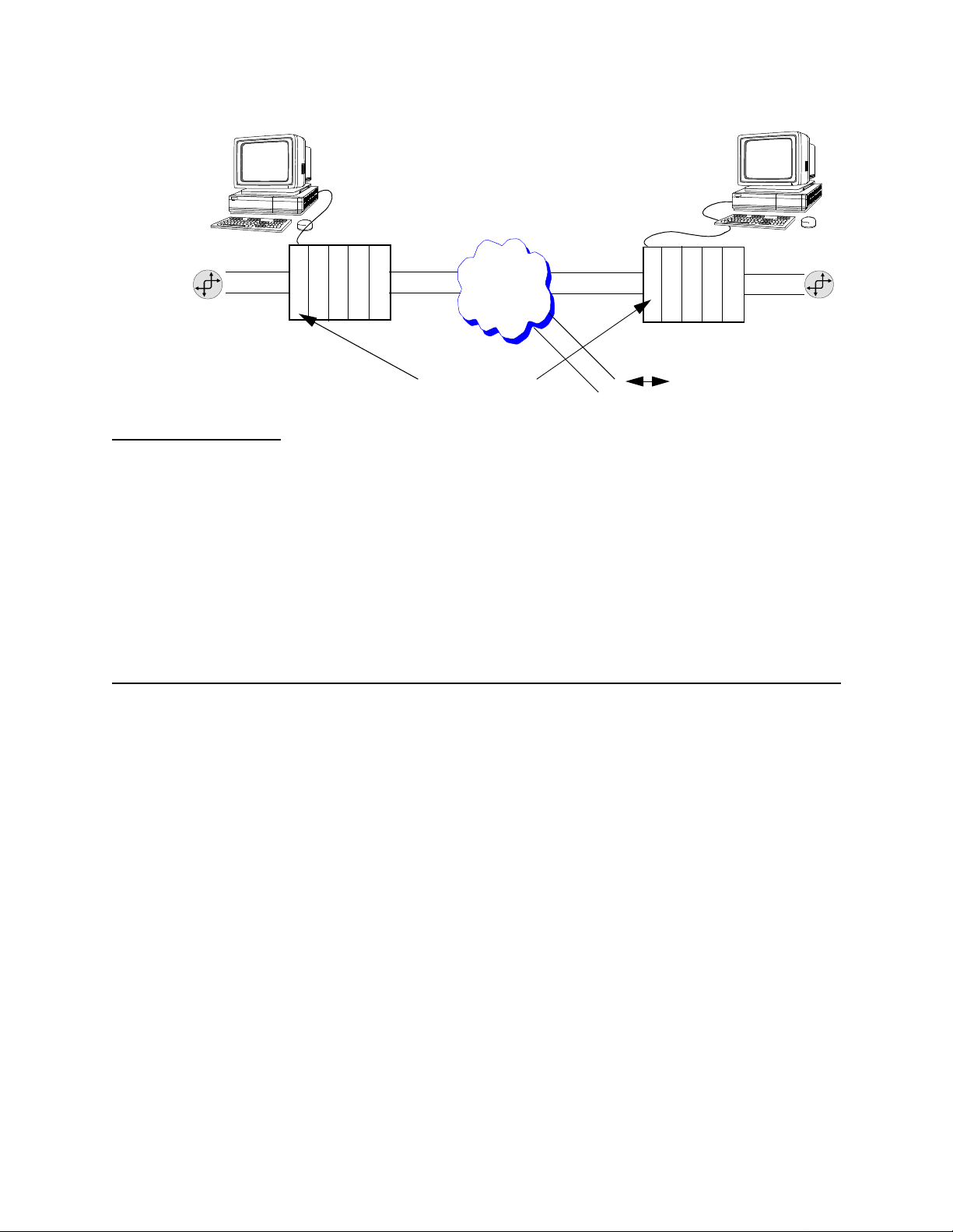
Figure 1-4 System Controller Module in a Multiple Application Network
SCM Overview
Manager
Craft Interface Port
Node
Q
D
A
T
A
Q
T
1
Craft
Interface
User-supplied compute
running Node Manager
or user-supplied ASCI I terminal
AS3000
Multi-line shelf
Q
Q
S
D
C
A
M
T
A
Near-end node
T1
T
1
T1
Management hosts
LEC/
Common
Carrier
T1
T1
T1
T1
AS3000
Multi-line shelf
S
C
M
Remote node
To other remote node
The Craft interface supports up to four simultaneous sessions:
•
One direct local connection
•
Up to three Telnet sessions over Ethernet or SLIP. To prevent
lockups of the Telnet server, it is recommended that only one
Telnet session be used during periods of heavy alarm activity.
Ethernet connectivity conforms to DIX and IEEE standards and is
supported through th e AAUI con nector port on th e rear p anel and a
provided transceiver with both 10BaseT and 10Base2 ports.
SNMP Clients
The SCM supports SNMP-based clients such as Node Manager and
HP OpenView™, Manager of Managers (MoMs), over Ethernet or
SLIP.
Adherence to ITU/ANSI/IETF specifications is required to ensure
compatibility and interoperability with complimentary SNMP
products. For more inf orma tio n o n SN MP and V eril ink pro duct s see
the SNMP Management Manual.
The SCM supports AS2000 node configuration by allowing
appropriate values to be assigned to and collected from the
configuration management objects defined in the supported MIBs.
Management application protocols suc h as Node Manager make use
of the MIBs.
The SCM 3000 does not support MIB II.
Verilink SCM 1-7
Page 18

SCM Overview
Verilink Enterprise MIBs
Verilink Vendor Number
MIBs are supplied as part of the software distributions for the
respective products.
•
Verilink Enterprise AS3000 generic MIB
•
Verilink Enterprise GENERAL MIB
•
Verilink Enterprise NCM VERI MIB
•
Verilink Enterprise NCM M13 MIB
•
Verilink Enterprise NCM IMUX MIB
A vendor number is a number that the SNMP Manager of Managers
(MOM) can use to isolate information about any vendor’s
equipment for viewing. For example, you might want to look at all
the traps sent by Verilink equipment.
Verilink’s vendor number is 1.3.6.1.4.1.321.1.1.
Verilink’s vendor number for the SCM card is 1.3.6.1.4.1.321.11
Environmental Specifications
Table 1-2 Non-operating Environmental Specs
Specification Value (or range)
Storage Temperature Range -20 to +80
Max Rate of Temperature Ch ange 8
Humidity 0% to 95% relative humidity, non-condensing
Vibration in Transport 0.5G from 5 Hz, 3.0G from50 Hz to 500 Hz
Shock During Shippi ng 20 msec, 25G half sine shock pulse
C per hour
°°°°
80 G peak, half sine for 10 msec
C
°°°°
1-8 Verilink SCM
Page 19

Table 1-3 Operating Environmental Specs
Specification Value (or range)
Temperature Range 0 to 50×C
Moisture 0% to 95% relative humidity, non-condensing
Airborne Contamination 0 to 75 micrograms per cubic meter
Noise to 75 dBA
Power Consumption 10 Watts total front and back modules
Heat Dissipation 34 BTU
Related Verilink Documents
Refer to the followin g AS3000 documentation for more
information:
•
Node Manager Installation Guide
•
Node Manager Online Help
SCM Overview
•
Verilink AS3000: The Basics—Information on installing and
replacing shel ves, modules, and power supplies, and general
information on the AS3000
•
Application module manuals—such as QUAD T1, QUAD DATA,
IMUX, and M1-3 user manuals
•
Craft Interface Manual
•
SNMP Management Manual
Verilink SCM 1-9
Page 20

SCM Overview
1-10 Verilink SCM
Page 21

Chapter
2
Installation
Craft Interface
Administration Menu
SCM Quick Set-Up
This chapter outlines the basic flow of procedures and options for
getting an SCM up and running.
The SCM boots fastest if it is located in shelf 0, slot 1. Insert the
NIM 3000 first, then the SCM.
Connecting to the Craft interface: see Chapter 3, “Craft Interface”,
or the Craft Interface Manual.
The SCM
parameters, see Chapter 4, “Administration Menu”.
Administration Menu
is used to set the system
System Parameters
Node Manager
SNMP, Telnet, or
SLIP Access
Configuring Local Modules
The following parameters mus t be set before proceeding:
•
Shelf type, see page 4-6, “Set Shelf Type”
•
Site name, see Table 4-2, “Administration Menu Commands”
•
Time/date/zone, see Table 4-2, “Administration Menu
Commands”
•
Passwords (optional), see pa ge 4-7, “Using Passwords”
Set the node address and node ID see “Administration Menu
Commands”.
SNMP, FTP or Telnet can be used through an Ethernet or SLIP
connection. If SNMP, Telnet, or SLIP is used to manage the node, set
the TCP/IP parameters. See page 4-10, “TheTCP/IP Configuration
Menu”.
From SCM, Craft, SNMP MoM, or Node Manager, configure the ports
after the system parameters have been set and before building any
circuits.
Circuit Build
Build the desired circuits between modules, see Ch apter 5, “Circuit
Manager”.
Verilink SCM 2-1
Page 22

SCM Quick Set-Up
Remote Configuration
Enable Alarms
The initial installation and configuration of a node must be done in
person, rather than remotely.
To configure the far-end node:
•
Set the node addr e ss .
•
Configure the M1-3 that will be used to access the site.
•
The same steps may be followed as for local configuration
once the remote node is accessible.
Enable alarm reporting at all ports, modul es, and the SCM, see page
3-13, “Alarms” for further information.
2-2 Verilink SCM
Page 23

Chapter
3
Accessing Remote Nodes
Use SCM Craft Interface
Craft Interface
This chapter introduces the SCM Craft interface and describes in
detail the
The SCM can shift its point of view to any SCM-supported module
in the local node or in a remote SCM-controlled node in the same
network. Remote access is accomplished through inband
management messages using the Facili ti es Data Link (FDL) for T1
and C-bit overhead for T3. Node selection is a function of the
Administration Menu
It is important to use the SCM interface for configuring modules.
Using the SCM enables building and maintaining a database of all
installed modules and every configured port and circuit. Most of
the modules managed by the SCM have their own Craft interface.
However, if the modules’ local Craft interfaces are used, some
configurations may fail. The local configuration of the shelf sync
table will fail, for example.
Main Menu
(the SCM
.
Controller Menu
).
Firmware Variations
Starting a Session
Since there are many application modules, application-specific
Craft interfaces appear in the user manual for the corresponding
application module, rather than in this manual. For example, QUAD
DATA configuration parameters are described in the QUAD DATA
user manual.
Each module (whether SCM or an application) has its own firmware
and release version level. When navigating through an SCM network
or node, the view of the Craft interface is subject to change
according to th e fir m w ar e of the module that is se l e cte d .
To communicate via the Craft interface with an SCM node, from an
ASCII terminal:
1. Connect the DB-9 Craft cable (P/N 458-102119-008) from the
OCAL
PC to the SCM front pa n el
For cable pinout information, see the manual AS3000 : The
Basics.
L
port.
Verilink SCM 3-1
Page 24

Craft Interface
2. Set your terminal parameters to the following values:
•
19.2 kbit/s
•
8 data bits
•
no parity
•
one stop-bit
•
no flow-control
Using Telnet
NOTE:
Ensure that both ha rdware flow control an d X-On/X-Off flow
control are disabled.
NTER
3. Press
E
to get a prompt.
The prompt displays:
pSH+>
The P-shell is a level below the Craft interface program.
4. To start the Craft interface, type:
“craft”
5. You are prompted:
YOUR PASSWORD?
NTER
E
6. If you’re accessing the node for the first time, press
PASSWORD?
the
Until you change it,
prompt.
NTER
E
is the default password.
at
Accessing the SCM Craft interface via Telnet requires that you have
previously configured the Ethernet IP address and related
parameters. The Craft inte rf ace of the local port must be used at
least once to set up the IP address of the SCM before Telnet can be
used.
In a shell, terminal, browser, or Telnet application window, use a
command similar to the following:
C:\> telnet 192.94.46 .54 (use the SCM IP address)
A message indicates you have connected to the SCM node:
Figure 3-1 Telnet Session Connecting to the SCM Node
Trying 192.94.46.54 ...
Trying 192.94.46.54 ...
Trying 192.94.46.54 ...Trying 192.94.46.54 ...
Connected to 192.94.46.54.
Connected to 192.94.46.54.
Connected to 192.94.46.54.Connected to 192.94.46.54.
Escape character is '^]'.
Escape character is '^]'.
Escape character is '^]'.Escape character is '^]'.
pSOSystem (192.94.46.54)
pSOSystem (192.94.46.54)
pSOSystem (192.94.46.54)pSOSystem (192.94.46.54)
Copyright (c) Integrated Systems, Inc., 1992.
Copyright (c) Integrated Systems, Inc., 1992.
Copyright (c) Integrated Systems, Inc., 1992.Copyright (c) Integrated Systems, Inc., 1992.
Welcome to pSOSystem...
Welcome to pSOSystem...
Welcome to pSOSystem...Welcome to pSOSystem...
pSH+>
pSH+>
pSH+>pSH+>
3-2 Verilink SCM
Page 25

Craft Interface
Bootup Messages
Messages are displayed during bootup to inform the user of bootup
progress. These messages vary from boot to boot. They depend on
the state of the SCM the last time it was booted and the flash
partition that is intended to be active. The following may display:
Table 3-1 Bootup Messages
Item Explanation
cnf_read_item, xxxxx, xxxx
cnf_write_item, xxxxx, xxxx
pNA+ configuration table setup
pNA+ stack intalled
Installing SONIC network interface
SONIC network interface insta lle d
No IP address assigned
flash.init: base=xxx lenth=xxx
EEPROM is being read
EEPROM is being written to
PSOS is being setup
PSOS is being setup
Ethernet interface is initialized
Ethernet interface is initialized
Ethernet interface is initialized
(Displays even if IP address
exists, so this message may be
disregarded)
Flash has been checked and is OK
for the memory range specified
The above items will display once if booted to partition A, twice if
booting to partition B.
Once the SCM low level initialization is complete (partition is
activated), the high level initialization begins with the following
information displayed:
Table 3-2 High Level Initialization
Item Explanation
firmware ver xxxx, made xxxxx
RAM disk initialized
Disk Volume Initialize
Copyright (c) Integrated Systems, Inc.1992
Welocme to pSOSystem...
pSH+>
Identifies firmware revision level.
SCM memory is partitioned
SCM RAM disk is initialized
SCM database is initialized
When you are in the Craft interface's P-shell, the prompt is
displayed as:
pSH+>
Now type the command to start the Craft interface session:
pSH+> craft
You are prompted:
YOUR PASSWORD?
Verilink SCM 3-3
Page 26

Craft Interface
If you’re accessing the node for the first time, press
PASSWORD?
prompt. Until you change it,
NTER
E
is the default
password.
NTER
E
at the
The SCM Controller
Figure 3-2 SCM Main Menu
Menu Heading Area
-- VERILINK SCM CONTROLLER : FW Rev 1.29, Nov 13 1998 16:53:13 --
-- VERILINK SCM CONTROLLER : FW Rev 1.29, Nov 13 1998 16:53:13 --
-- VERILINK SCM CONTROLLER : FW Rev 1.29, Nov 13 1998 16:53:13 ---- VERILINK SCM CONTROLLER : FW Rev 1.29, Nov 13 1998 16:53:13 --
Site name: SCM Tutorial Access level: 2
Site name: SCM Tutorial Access level: 2
Site name: SCM Tutorial Access level: 2 Site name: SCM Tutorial Access level: 2
Managing at NEAR end node [0.0.0.2] Node id: 122
Managing at NEAR end node [0.0.0.2] Node id: 122
Managing at NEAR end node [0.0.0.2] Node id: 122 Managing at NEAR end node [0.0.0.2] Node id: 122
<- SLOT ->
<- SLOT ->
<- SLOT -> <- SLOT ->
SHELF 1 2 3 4 5 6 7 8 9 10 11 12 13
SHELF 1 2 3 4 5 6 7 8 9 10 11 12 13
SHELF 1 2 3 4 5 6 7 8 9 10 11 12 13 SHELF 1 2 3 4 5 6 7 8 9 10 11 12 13
0 - - - - - - - - - - - - -
Shelf/Slot Map
Module Key
Command List
0 - - - - - - - - - - - - -
0 - - - - - - - - - - - - - 0 - - - - - - - - - - - - -
❶
1 M [*S] D Q Q I M D - - - - - -
1 M [*S] D Q Q I M D - - - - - -
1 M [*S] D Q Q I M D - - - - - - 1 M [*S] D Q Q I M D - - - - - 2 - - - - - - - - - - - - -
2 - - - - - - - - - - - - -
2 - - - - - - - - - - - - - 2 - - - - - - - - - - - - 3 - - - - - - - - - - - - -
3 - - - - - - - - - - - - -
3 - - - - - - - - - - - - - 3 - - - - - - - - - - - - 4 - - - - - - - - - - - - -
4 - - - - - - - - - - - - -
4 - - - - - - - - - - - - - 4 - - - - - - - - - - - - KEY: D=QUAD D, I=IMUX, M=M1-3, Q=QUAD T1, S=SCM
KEY: D=QUAD D, I=IMUX, M=M1-3, Q=QUAD T1, S=SCM
KEY: D=QUAD D, I=IMUX, M=M1-3, Q=QUAD T1, S=SCMKEY: D=QUAD D, I=IMUX, M=M1-3, Q=QUAD T1, S=SCM
S) shelf/slot O) administration
S) shelf/slot O) administration
S) shelf/slot O) administrationS) shelf/slot O) administration
C) configuration D) diagnostics
C) configuration D) diagnostics
C) configuration D) diagnosticsC) configuration D) diagnostics
P) performance/status A) alarm
P) performance/status A) alarm
P) performance/status A) alarmP) performance/status A) alarm
B) circuit manager I) manufacturing info
B) circuit manager I) manufacturing info
B) circuit manager I) manufacturing infoB) circuit manager I) manufacturing info
X) logoff
X) logoff
X) logoffX) logoff
❷❸
Main Menu
Firmware Version and Date of Release
Node Address
displays:
Access Level (1-4)
A [0.0.0.2] [1,1] SCM >
A [0.0.0.2] [1,1] SCM >
A [0.0.0.2] [1,1] SCM >A [0.0.0.2] [1,1] SCM >
Node Address (Not IP Address)
Active SCM Master Designator
Indicator for the type of shelf: M= Multi-line, Q=Quint-line
❶
Asterisk indicates that the SCM is the Shelf Controller
❷
Brackets around module letter ( [S] ) indicate current module selected
❸
3-4 Verilink SCM
Data (Command) Entry Area
Page 27

The Main Menu
Craft Interface
Menu Heading
Firmware Version
The SCM
•
•
•
•
•
The menu heading area provides system-level information for the
node.
The firmware version release level appears on the top line. The SCM
has a revision number series distinct from that of individual
application modules.
NOTE:
Main Menu,
node information
a display showing shelf type and module locations in the shelf
a legend decoding the alphabetic char acters for the modules in
the slots
a command menu
firmware revision number
The version levels shown in screen samples are placeholders
only and do not refl ect the version leve l(s) as they may
appear in your system. Firmware revision levels vary
according to se ve ral factors, inc lu ding special fir mw a r e
generated for specific customers, as well as more generic
versions.
shown in Figure 3-2, provides:
Site Name
Node Address
Access Level
Node ID
The site name is entered in the SCM
The node address is a unique Verilink a ddress for e ach m aster SCM
in the network. Set it using the SCM
structure similar to an IP address.
The Access Level 2 shown in Figure 3-2 indicates the current user is
at the Privileged level. The four password levels are further
described in Chapte r 4, “Using Passwords”.
The node ID is used by Verilink’ s Node Manager to identify each
node in the network. Set it using the SCM
Administration Menu
Administration Menu
Administration Menu
.
. It has a
.
Verilink SCM 3-5
Page 28

Craft Interface
Shelf/Slot Map
Shelf Symbols
Node Map
Selection Brackets
Directly to the right of the Shelf column:
The M next to Shelf 1 indicates it is a Multi-line Shelf. A lower-case
m
indicates that the shelf type has not yet been set properly in the
Administration Menu
SCM
before the using the shelf.
A Q next to a shelf indicates a Quint-line Shelf. The shelf may not
be correctly recognized as a quint-line shelf until the shelf type is
set in the SCM
The node map graphically represents the type of shelf, the
shelf/slot locations, and the type of module in each location.
Each module is represented in the matrix display by a character.
The key to these symbols is included in the screen, beneath the
shelf/slot matrix. See Table 3-3.
The shelf master is indicated by an asterisk (*). When an SCM
module is present, it should be the shelf master. In the absence of
an SCM, another module will become shelf master.
Brackets around a module in the shelf (for example:
is currently selected.
Administration Menu.
. The shelf type must be manually set
[S]
) indicate it
Unknown
Module Key
A question mark
firmware of the SCM does not know about the module in the
shelf/slot location. It can also mean the application module does
not have the correct CIM .
A hyphen
location is empty.
If the word “UNKNOWN” appears in place of the name of one of the
modules in the legend, it means one of the following conditions:
•
•
•
Application modules are represented in the matrix display by
alphabetic characters. The key to these symbols is included in the
Main Menu
Figure 3-2 are described in Table 3-3.
[-]
the current firmware does not know about the element
the slot is empty
the module recently has been pulled out.
[?]
in place of an element symbol indicates the
in place of a module symbol indicates the shelf/slot
, beneath the Shelf/Slot map. The key elements in
3-6 Verilink SCM
Page 29

Table 3-3 Detailed Key Description
Craft Interface
Command Line Prompt
Key Symbol and
Name
D=QUAD DATA QUAD DATA 4 DTE ports
I=IMUX Inverse Multiplexer 1 DTE port
M=M1-3 M1-3 DS3 Multiplexer 1 DS3 port
Q=QUAD T1 QUAD T1 4 T1 ports
S=SCM System Controller
Generic Name Comment
Module
Management only—no
traffic
The currently selected module is indicated in the command line
prompt. The four-part number shown on this line is not an
Ethernet IP address. It is a Verilink-specific node address used to
identify this SCM.
The initial prompt defaults to the node address of the local SCM.
The command line prompt is interpreted as follows:
[0.0.0.1] [0,11] SCM >
Where:
[0.0.0.1]
is the node address of the local node to which
you are connected. This number is used by
SCM modules and the Verilink Node Manager
application to identify each SCM (and node).
This value is completely unrelated to the
Ethernet IP address of the SCM.
Selecting a Module
NOTE:
Each SCM must have a unique node address as shown in the
command line prom pt.
[0,11]
is the shelf number and slot number of the
currently selected module.
SCM>
is the command line prompt, showing the
model name of the currently selected module.
If you select a shelf/slot location that is empty or
from which the element has been pulled out, this
field reads:
To select a module in the node to manage, select the command
option for choosing the shelf and slot:
S) shelf/slot
as shown in the following example command line:
[0.0.0.1] [1,1] SCM > s
UNKNOWN >.
Verilink SCM 3-7
Page 30

Craft Interface
The next prompt shows the input f ormat:
Enter 'shelf,slot' pair or 'slot' in current shelf(e.g. 3,4 or 5): >
Enter the shelf and slot location of the module to manage. In this
example, suppose you wish to configure a port on the QUAD T1
located in shelf 1, slot 3. This module is represented by a Q, which
the Key below the shelf/slot display identifies as a QUAD T1. You
would type in response to the prompt:
"1,3".
You may shorten this entry and specify only the slot to select a
module on the current shelf. To go from slot 1 to slot 5 in the
current shelf, enter the following at the prompt:
"5".
When the
Main Menu
is redisplayed the bracket-indicator (
moved to enclose the Q.
Figure 3-3 SCM Main Menu for QUAD T1
-- VERILINK SCM CONTROLLER : FW Rev 1.29, Nov 13 1998 16:53:13 --
-- VERILINK SCM CONTROLLER : FW Rev 1.29, Nov 13 1998 16:53:13 --
-- VERILINK SCM CONTROLLER : FW Rev 1.29, Nov 13 1998 16:53:13 ---- VERILINK SCM CONTROLLER : FW Rev 1.29, Nov 13 1998 16:53:13 --
Site name: SCM Tutorial Access level: 2
Site name: SCM Tutorial Access level: 2
Site name: SCM Tutorial Access level: 2 Site name: SCM Tutorial Access level: 2
Managing at NEAR end node [0.0.0.2] Node id: 122
Managing at NEAR end node [0.0.0.2] Node id: 122
Managing at NEAR end node [0.0.0.2] Node id: 122 Managing at NEAR end node [0.0.0.2] Node id: 122
<- SLOT ->
<- SLOT ->
<- SLOT -> <- SLOT ->
SHELF 1 2 3 4 5 6 7 8 9 10 11 12 13
SHELF 1 2 3 4 5 6 7 8 9 10 11 12 13
SHELF 1 2 3 4 5 6 7 8 9 10 11 12 13 SHELF 1 2 3 4 5 6 7 8 9 10 11 12 13
0 - - - - - - - - - - - - -
0 - - - - - - - - - - - - -
0 - - - - - - - - - - - - - 0 - - - - - - - - - - - - 1 M *S - [Q] Q I M D - - - - - -
1 M *S - [Q] Q I M D - - - - - -
1 M *S - [Q] Q I M D - - - - - - 1 M *S - [Q] Q I M D - - - - - 2 - - - - - - - - - - - - -
2 - - - - - - - - - - - - -
2 - - - - - - - - - - - - - 2 - - - - - - - - - - - - 3 - - - - - - - - - - - - -
3 - - - - - - - - - - - - -
3 - - - - - - - - - - - - - 3 - - - - - - - - - - - - 4 - - - - - - - - - - - - -
4 - - - - - - - - - - - - -
4 - - - - - - - - - - - - - 4 - - - - - - - - - - - - KEY: D=QUAD D, I=IMUX, M=M1-3, Q=QUAD T1, S=SCM
KEY: D=QUAD D, I=IMUX, M=M1-3, Q=QUAD T1, S=SCM
KEY: D=QUAD D, I=IMUX, M=M1-3, Q=QUAD T1, S=SCMKEY: D=QUAD D, I=IMUX, M=M1-3, Q=QUAD T1, S=SCM
S) shelf/slot O) administration
S) shelf/slot O) administration
S) shelf/slot O) administrationS) shelf/slot O) administration
C) configuration D) diagnostics
C) configuration D) diagnostics
C) configuration D) diagnosticsC) configuration D) diagnostics
P) performance/status A) alarm
P) performance/status A) alarm
P) performance/status A) alarmP) performance/status A) alarm
B) circuit manager I) manufacturing info
B) circuit manager I) manufacturing info
B) circuit manager I) manufacturing infoB) circuit manager I) manufacturing info
R) remote end setup
R) remote end setup
R) remote end setupR) remote end setup
X) logoff
X) logoff
X) logoffX) logoff
[ ])
has
A [0.0.0.2] [1,3] QUAD T1 >
A [0.0.0.2] [1,3] QUAD T1 >
A [0.0.0.2] [1,3] QUAD T1 > A [0.0.0.2] [1,3] QUAD T1 >
The command-line prompt reflects your selection in the shelf and
slot field (Shelf 1, Slot 3 in this case) and the module type
displayed in the comman d line (Q UA D T1 ).
Main Menu Options
This section provides a brief description of selections on the
Menu
.
3-8 Verilink SCM
Main
Page 31

Craft Interface
Administration
Configuration
SCM
The O command displays the SCM
Node Administration Menu
.
This menu is covered in detail in the next chapter, see Chapter 4,
“Administration Menu”.
The Configuration command, C, brings up the
Configuration Menu
for the currently selected card.
If the SCM is the currently selected card, the configuration
command returns this menu:
Figure 3-4 SCM Configuration Menu
-- SCM CONFIGURATION MENU --
-- SCM CONFIGURATION MENU --
-- SCM CONFIGURATION MENU ---- SCM CONFIGURATION MENU --
Feature does not apply to this card(SCM/7f)
Feature does not apply to this card(SCM/7f)
Feature does not apply to this card(SCM/7f)Feature does not apply to this card(SCM/7f)
Press Enter to continue
Press Enter to continue
Press Enter to continue Press Enter to continue
Other Modules
If the currently selected card is other than an SCM module, the
Configuration Menu
In Figure 3-5, the sample is the
Menu
. (For more information on the latter menu, see the QUAD
for that card will appear.
QUAD DATA Port Configur ation
DATA User Manual.)
Each application module has its own specific configuration
parameters for the module , and for the data and network ports it
supports.
Verilink SCM 3-9
Page 32

Craft Interface
Figure 3-5 QUAD DATA Configuration Menu
-- QUAD DATA CONFIGURATION MENU --
-- QUAD DATA CONFIGURATION MENU --
-- QUAD DATA CONFIGURATION MENU ---- QUAD DATA CONFIGURATION MENU --
Port 1 Port 2 Port 3 Port 4
Port 1 Port 2 Port 3 Port 4
Port 1 Port 2 Port 3 Port 4 Port 1 Port 2 Port 3 Port 4
In) in service yes yes yes yes
In) in service yes yes yes yes
In) in service yes yes yes yesIn) in service yes yes yes yes
Fn) interface type EIA-530 RS-449 RS-449 V.35
Fn) interface type EIA-530 RS-449 RS-449 V.35
Fn) interface type EIA-530 RS-449 RS-449 V.35Fn) interface type EIA-530 RS-449 RS-449 V.35
Mn) data port mode DCE DTE DTE DCE
Mn) data port mode DCE DTE DTE DCE
Mn) data port mode DCE DTE DTE DCEMn) data port mode DCE DTE DTE DCE
Cn) clock option ST --- --- ST
Cn) clock option ST --- --- ST
Cn) clock option ST --- --- STCn) clock option ST --- --- ST
On) enable LOS detect no no no no
On) enable LOS detect no no no no
On) enable LOS detect no no no noOn) enable LOS detect no no no no
An) remote loopback no no no no
An) remote loopback no no no no
An) remote loopback no no no noAn) remote loopback no no no no
Ln) X.21 C/I setting --- --- --- ---
Ln) X.21 C/I setting --- --- --- ---
Ln) X.21 C/I setting --- --- --- ---Ln) X.21 C/I setting --- --- --- --SRn) DTR/DSR setting DSR/normal DTR/normal DTR/normal DSR/normal
SRn) DTR/DSR setting DSR/normal DTR/normal DTR/normal DSR/normal
SRn) DTR/DSR setting DSR/normal DTR/normal DTR/normal DSR/normalSRn) DTR/DSR setting DSR/normal DTR/normal DTR/normal DSR/normal
SSn) RTS/CTS setting CTS/normal RTS/normal RTS/normal CTS/normal
SSn) RTS/CTS setting CTS/normal RTS/normal RTS/normal CTS/normal
SSn) RTS/CTS setting CTS/normal RTS/normal RTS/normal CTS/normalSSn) RTS/CTS setting CTS/normal RTS/normal RTS/normal CTS/normal
SDn) DCD/LL setting DCD/normal LL /off LL /off DCD/normal
SDn) DCD/LL setting DCD/normal LL /off LL /off DCD/normal
SDn) DCD/LL setting DCD/normal LL /off LL /off DCD/normalSDn) DCD/LL setting DCD/normal LL /off LL /off DCD/normal
SMn) TM/RL setting TM /off RL /off RL /off TM /off
SMn) TM/RL setting TM /off RL /off RL /off TM /off
SMn) TM/RL setting TM /off RL /off RL /off TM /offSMn) TM/RL setting TM /off RL /off RL /off TM /off
C) copy port T) timing
C) copy port T) timing
C) copy port T) timingC) copy port T) timing
X) exit this menu
X) exit this menu
X) exit this menuX) exit this menu
A [0.0.0.2] [1,2] QUAD DATA >
A [0.0.0.2] [1,2] QUAD DATA >
A [0.0.0.2] [1,2] QUAD DATA > A [0.0.0.2] [1,2] QUAD DATA >
Diagnostics
Diagnostics are not required for the SCM itself. Since it does not
handle user data, the SCM controls diagnostics on other modules
that do handle user data.
To perform diagnostics on a module, go to the Main Menu, select a
module by using the
diagnostics
.
S) shelf/slot
An example of an IMUX module
command, then select
Diagnostics Menu
is shown in
D)
Figure 3-6.
3-10 Verilink SCM
Page 33

Figure 3-6 IMUX Diagnostics Menu
-- IMUX DIAGNOSTICS MENU --
-- IMUX DIAGNOSTICS MENU --
-- IMUX DIAGNOSTICS MENU ---- IMUX DIAGNOSTICS MENU --
Data Port Type: V.35
Data Port Type: V.35
Data Port Type: V.35Data Port Type: V.35
AIS Pattern: DISABLE
AIS Pattern: DISABLE
AIS Pattern: DISABLEAIS Pattern: DISABLE
Loopback: NONE
Loopback: NONE
Loopback: NONELoopback: NONE
1 2 3 4 5 6 7 8
1 2 3 4 5 6 7 8
1 2 3 4 5 6 7 8 1 2 3 4 5 6 7 8
Lines Equipped: X X X X
Lines Equipped: X X X X
Lines Equipped: X X X XLines Equipped: X X X X
Lines Active:
Lines Active:
Lines Active:Lines Active:
Frame Sync:
Frame Sync:
Frame Sync:Frame Sync:
CTS Received:
CTS Received:
CTS Received:CTS Received:
CRC Error:
CRC Error:
CRC Error:CRC Error:
Far CRC Error:
Far CRC Error:
Far CRC Error:Far CRC Error:
E) Equipment Loopback P) Payload Loopback
E) Equipment Loopback P) Payload Loopback
E) Equipment Loopback P) Payload LoopbackE) Equipment Loopback P) Payload Loopback
A) AIS Pattern X) main menu
A) AIS Pattern X) main menu
A) AIS Pattern X) main menuA) AIS Pattern X) main menu
A [0.0.0.2] [1,5] IMUX >
A [0.0.0.2] [1,5] IMUX >
A [0.0.0.2] [1,5] IMUX > A [0.0.0.2] [1,5] IMUX >
Craft Interface
Performance and Status
Performance and status functions are used to evaluate the
operation of application modules and the network facilities they
use. Modules that connect to network facilities such as T1 or T3
circuits will usually have statistics on circuit performance for the
preceeding 24 hours.
Performance and status for the SCM are not applicable, since the
SCM module does not connect to any customer equipment or
circuits. The following message appears if this option is selected
on the SCM module:
-- SCM PERFORMANCE/STATUS MENU --
-- SCM PERFORMANCE/STATUS MENU --
-- SCM PERFORMANCE/STATUS MENU ---- SCM PERFORMANCE/STATUS MENU --
Feature does not apply to this card(SCM/7f)
Feature does not apply to this card(SCM/7f)
Feature does not apply to this card(SCM/7f)Feature does not apply to this card(SCM/7f)
Press Enter to continue
Press Enter to continue
Press Enter to continue Press Enter to continue
The performance information stored in each application module
may be viewed by first selecting the module using the
command and then selecting the
P) performance/status
shelf/slot
.
[0.0.0.1] [1,5] IMUX > p
Shown below is the
module.
Verilink SCM 3-11
Performance/Status Menu
for an IMUX
Page 34

Craft Interface
Figure 3-7 Example of IMUX 2160 Performance/Status Menu
-- IMUX PERFORMANCE/STATUS MENU --
-- IMUX PERFORMANCE/STATUS MENU --
-- IMUX PERFORMANCE/STATUS MENU ---- IMUX PERFORMANCE/STATUS MENU --
Data Port Type: V.35
Data Port Type: V.35
Data Port Type: V.35Data Port Type: V.35
AIS Pattern: DISABLE
AIS Pattern: DISABLE
AIS Pattern: DISABLEAIS Pattern: DISABLE
Loopback: NONE
Loopback: NONE
Loopback: NONELoopback: NONE
1 2 3 4 5 6 7 8
1 2 3 4 5 6 7 8
1 2 3 4 5 6 7 8 1 2 3 4 5 6 7 8
Lines Equipped: X X X X
Lines Equipped: X X X X
Lines Equipped: X X X XLines Equipped: X X X X
Lines Active:
Lines Active:
Lines Active:Lines Active:
Frame Sync:
Frame Sync:
Frame Sync:Frame Sync:
CTS Received:
CTS Received:
CTS Received:CTS Received:
CRC Error:
CRC Error:
CRC Error:CRC Error:
Far CRC Error:
Far CRC Error:
Far CRC Error:Far CRC Error:
Press enter to continue
Press enter to continue
Press enter to continuePress enter to continue
Alarms
A primary function of the SCM is handling alarm messages from the
application modules. Alarms will be sent to an SNMP manager or
Verilink’s Node Manager if the TCP/IP options under the
Configuration
configured. See “TheTCP/IP Configuration Menu” in Chapter 3.
The SCM also displays alarm messages in real time to the Craft
interface. The Alarm command displays the
for the currently selected module. If the SCM is selected, the
following menu displays:
Figure 3-8 Alarm Options Menu
-- SCM ALARM MENU --
-- SCM ALARM MENU --
-- SCM ALARM MENU ---- SCM ALARM MENU --
-- Alarm Conditions --
-- Alarm Conditions --
-- Alarm Conditions -- -- Alarm Conditions --
<- SLOT ->
<- SLOT ->
<- SLOT -> <- SLOT ->
SHELF 1 2 3 4 5 6 7 8 9 10 11 12 13
SHELF 1 2 3 4 5 6 7 8 9 10 11 12 13
SHELF 1 2 3 4 5 6 7 8 9 10 11 12 13 SHELF 1 2 3 4 5 6 7 8 9 10 11 12 13
0 - - - - - - - - - - - - -
0 - - - - - - - - - - - - -
0 - - - - - - - - - - - - - 0 - - - - - - - - - - - - 1 M C C C C C A A - - - - - -
1 M C C C C C A A - - - - - -
1 M C C C C C A A - - - - - - 1 M C C C C C A A - - - - - 2 - - - - - - - - - - - - -
2 - - - - - - - - - - - - -
2 - - - - - - - - - - - - - 2 - - - - - - - - - - - - 3 - - - - - - - - - - - - -
3 - - - - - - - - - - - - -
3 - - - - - - - - - - - - - 3 - - - - - - - - - - - - 4 - - - - - - - - - - - - -
4 - - - - - - - - - - - - -
4 - - - - - - - - - - - - - 4 - - - - - - - - - - - - Legend: A = in alarm, B = alarming blocked, C = alarms clear
Legend: A = in alarm, B = alarming blocked, C = alarms clear
Legend: A = in alarm, B = alarming blocked, C = alarms clear Legend: A = in alarm, B = alarming blocked, C = alarms clear
submenu of the
Administration Menu
Alarm Options Menu
Network
are properly
M) alarm monitoring: no
M) alarm monitoring: no
M) alarm monitoring: noM) alarm monitoring: no
I) relay inhibit
I) relay inhibit
I) relay inhibitI) relay inhibit
A) display alarm buffer
A) display alarm buffer
A) display alarm bufferA) display alarm buffer
C) clear alarm buffer
C) clear alarm buffer
C) clear alarm bufferC) clear alarm buffer
X) exit this menu
X) exit this menu
X) exit this menuX) exit this menu
A [0.0.0.2] [1,1] SCM >
A [0.0.0.2] [1,1] SCM >
A [0.0.0.2] [1,1] SCM > A [0.0.0.2] [1,1] SCM >
3-12 Verilink SCM
Page 35

A shelf/slot matrix display of alar m status appears. Each loca tion is
mapped to a slot of a shelf. The meanings of the symbols shown
are listed in Table 3-4. The command options available on the
Alarms Menu
Table 3-4 Alarm Menu Key
Symbol Meaning
Craft Interface
are described in Table 3-5.
-
A Module has s ome al ar m con ditio n at t his time, use
BThe
C Module has no alarms at this time, any previous alarm s ha ve cle ared.
SCM sees no module in this slot.
to view current alarm details.
Relay Inhibit
of time, and this screen has been displayed duri ng this inhibited (blocked)
period.
option has been configured not to show alarms for a period
The following command options are available on the SCM
Menu
:
Table 3-5 Alarm Menu Commands
Command Function
M Alarm Monitoring. Toggles on/off the display of alarm messages in the Craft interface
screen. If ON, messages appear on the Craft interface term inal as alarms occur and
again as they clear.
I Relay Inhibit. Allows the user to enable, disable, or temporarily block the action of the
alarm relays. Valu es range from 0 to 256. Selecting zero enables i m mediate alarm
relay activation. Values from one to 255 block alarm relay operation for an equal
number of minutes. Selecting 256 disables the alarm relays. This might be used in a
large network to avoid tripping alarm relays when a specific circuit is scheduled for an
outage, or to block alarm relay operation on pending or non-critical facilities.
A) display alarm buffer
Alarm
A Display Alarm Buffer. Pr es en ts a history of al ar m messa ges to the Craft in terf ac e. See
C Clear Alarm Buffer. Removes all alarm messages from the display buffer referenced
X Exit. Returns to the SCM
the example in
above. User is not asked to confirm this selection. Not recommen ded except to clear
alarms after initial installation.
Figure 3-9
.
Main Menu
.
The following is an SCM alarm buffer display:
Verilink SCM 3-13
Page 36

Craft Interface
Figure 3-9 SCM Alarm Buffer Display
* 0.0.0.2 M1-3 [01,06] Minor alarm M13 T3 Port
* 0.0.0.2 M1-3 [01,06] Minor alarm M13 T3 Port
* 0.0.0.2 M1-3 [01,06] Minor alarm M13 T3 Port* 0.0.0.2 M1-3 [01,06] Minor alarm M13 T3 Port
(1/4 hour)DS3 LOFS alert reaches the threshold 11-13-98 2:55:21
(1/4 hour)DS3 LOFS alert reaches the threshold 11-13-98 2:55:21
(1/4 hour)DS3 LOFS alert reaches the threshold 11-13-98 2:55:21 (1/4 hour)DS3 LOFS alert reaches the threshold 11-13-98 2:55:21
* 0.0.0.2 M1-3 [01,06] Cleared alarm M13 T3 Port
* 0.0.0.2 M1-3 [01,06] Cleared alarm M13 T3 Port
* 0.0.0.2 M1-3 [01,06] Cleared alarm M13 T3 Port* 0.0.0.2 M1-3 [01,06] Cleared alarm M13 T3 Port
(1/4 hour)DS3 LOFS alert reaches the threshold 11-13-98 2:55:18
(1/4 hour)DS3 LOFS alert reaches the threshold 11-13-98 2:55:18
(1/4 hour)DS3 LOFS alert reaches the threshold 11-13-98 2:55:18 (1/4 hour)DS3 LOFS alert reaches the threshold 11-13-98 2:55:18
* 0.0.0.2 M1-3 [01,06] Minor alarm M13 T3 Port
* 0.0.0.2 M1-3 [01,06] Minor alarm M13 T3 Port
* 0.0.0.2 M1-3 [01,06] Minor alarm M13 T3 Port* 0.0.0.2 M1-3 [01,06] Minor alarm M13 T3 Port
(1/4 hour)DS3 LOFS alert reaches the threshold 11-13-98 2:40:21
(1/4 hour)DS3 LOFS alert reaches the threshold 11-13-98 2:40:21
(1/4 hour)DS3 LOFS alert reaches the threshold 11-13-98 2:40:21 (1/4 hour)DS3 LOFS alert reaches the threshold 11-13-98 2:40:21
* 0.0.0.2 M1-3 [01,06] Cleared alarm M13 T3 Port
* 0.0.0.2 M1-3 [01,06] Cleared alarm M13 T3 Port
* 0.0.0.2 M1-3 [01,06] Cleared alarm M13 T3 Port* 0.0.0.2 M1-3 [01,06] Cleared alarm M13 T3 Port
(1/4 hour)DS3 LOFS alert reaches the threshold 11-13-98 2:40:18
(1/4 hour)DS3 LOFS alert reaches the threshold 11-13-98 2:40:18
(1/4 hour)DS3 LOFS alert reaches the threshold 11-13-98 2:40:18 (1/4 hour)DS3 LOFS alert reaches the threshold 11-13-98 2:40:18
* 0.0.0.2 M1-3 [01,06] Minor alarm M13 T3 Port
* 0.0.0.2 M1-3 [01,06] Minor alarm M13 T3 Port
* 0.0.0.2 M1-3 [01,06] Minor alarm M13 T3 Port* 0.0.0.2 M1-3 [01,06] Minor alarm M13 T3 Port
(1/4 hour)DS3 LOFS alert reaches the threshold 11-13-98 2:25:21
(1/4 hour)DS3 LOFS alert reaches the threshold 11-13-98 2:25:21
(1/4 hour)DS3 LOFS alert reaches the threshold 11-13-98 2:25:21 (1/4 hour)DS3 LOFS alert reaches the threshold 11-13-98 2:25:21
* 0.0.0.2 M1-3 [01,06] Cleared alarm M13 T3 Port
* 0.0.0.2 M1-3 [01,06] Cleared alarm M13 T3 Port
* 0.0.0.2 M1-3 [01,06] Cleared alarm M13 T3 Port* 0.0.0.2 M1-3 [01,06] Cleared alarm M13 T3 Port
(1/4 hour)DS3 LOFS alert reaches the threshold 11-13-98 2:25:18
(1/4 hour)DS3 LOFS alert reaches the threshold 11-13-98 2:25:18
(1/4 hour)DS3 LOFS alert reaches the threshold 11-13-98 2:25:18 (1/4 hour)DS3 LOFS alert reaches the threshold 11-13-98 2:25:18
* 0.0.0.2 M1-3 [01,06] Minor alarm M13 T3 Port
* 0.0.0.2 M1-3 [01,06] Minor alarm M13 T3 Port
* 0.0.0.2 M1-3 [01,06] Minor alarm M13 T3 Port* 0.0.0.2 M1-3 [01,06] Minor alarm M13 T3 Port
(1/4 hour)DS3 LOFS alert cross the threshold 8-13-98 2:10:21
(1/4 hour)DS3 LOFS alert cross the threshold 8-13-98 2:10:21
(1/4 hour)DS3 LOFS alert cross the threshold 8-13-98 2:10:21 (1/4 hour)DS3 LOFS alert cross the threshold 8-13-98 2:10:21
-- MORE -- ('q' to quit)
-- MORE -- ('q' to quit)
-- MORE -- ('q' to quit)-- MORE -- ('q' to quit)
Circuit Manager
The display indicates date and time for each alarm. The shelf and
slot of the module reporting the alarm is shown in brackets
[01,06]
Whenever the SCM detects a module for the first time, an alarm is
reported,
Near-End Plug Present Alarm.
This does not indicate a
problem.
If a module other than the SCM is the currently selected module, an
Alarm Options Menu
for that module will appear when
Alarm
is
selected.
NOTE:
When using three Telnet sessions a “jammed” state may
occur in which too man y alarm messages are genera ted in
one session. The mes sages for the “jammed” session will not
be reported, even after the messages slow down. If the
“jammed” session is discontinued and reconnected, the
messages resume the proper routing.
Circuit Manager is used to create, edit and maintain connections
from one application module port to another application module
port, or intramodul e circuits when available (ex. QUAD T1).
Circuit Manager is covered in detail in Chapter 5, “Circuit
Manager”.
3-14 Verilink SCM
Page 37

Craft Interface
Manufacturing Info
This submenu displays hardware revision level, date of
manufacture, serial number and part number information for the
currently selected module. The front application module appears
under the heading "Main Card" and the Co nnector Inte rface Mod ule
in the rear is reported under the “CIM” column.
This information may be very useful if you need to contact Verilink
for assistance.
This screen is read-only to users of t he equipment. The information
is set in the card at time of manufacture and updated as need be
when a card is factory upgraded.
NOTE:
This information is not available for the IMUX modules in the
shelf.
Figure 3-10 shows a sample of Manufacturing Information Report.
Figure 3-10 Manufacturing Information Report
-- MANUFACTURING INFORMATION --
-- MANUFACTURING INFORMATION --
-- MANUFACTURING INFORMATION ---- MANUFACTURING INFORMATION --
Main Card CIM
Main Card CIM
Main Card CIM Main Card CIM
revision RM) A RC) A
revision RM) A RC) A
revision RM) A RC) Arevision RM) A RC) A
date DM) 11/8/98 DC) 11/8/98
date DM) 11/8/98 DC) 11/8/98
date DM) 11/8/98 DC) 11/8/98date DM) 11/8/98 DC) 11/8/98
serial number SM) 00622014 SC) 00643461
serial number SM) 00622014 SC) 00643461
serial number SM) 00622014 SC) 00643461serial number SM) 00622014 SC) 00643461
manuf. part no. MM) 319101697001 MC) 311101761001
manuf. part no. MM) 319101697001 MC) 311101761001
manuf. part no. MM) 319101697001 MC) 311101761001manuf. part no. MM) 319101697001 MC) 311101761001
cage code CM) CC)
cage code CM) CC)
cage code CM) CC)cage code CM) CC)
type TM) SCM TC) NIM 3000
type TM) SCM TC) NIM 3000
type TM) SCM TC) NIM 3000type TM) SCM TC) NIM 3000
Press Enter to continue
Press Enter to continue
Press Enter to continue Press Enter to continue
Module-Specific Menus
Pressing
NTER
E
returns you to the
Main Menu
.
When the SCM is used to select certain application modules, new
commands and functions display specific to those modules:
•
When managing an M1-3 module the pro mpt
End DS3 Port Identification
appears. This optional
F) Display Far
informational display provides a place to enter descriptions of
the facilities related to the port.
•
The QUAD T1 and M1-3 modules present
R) Remote End Setup
which enables configuration of certain far-end parameters
before inband management is enabled. Before leaving this
screen the
Update SCM Table
option should be used if any
changes have been made. The parameters which can be
changed in the far-end product are:
•
Node address
Verilink SCM 3-15
Page 38

Craft Interface
•
Node ID
•
Inband state
•
Update SCM table (saves this info to node list)
Port Indicator
Commands
Some commands are shown with a lowercase character. The
character, usually n, re presents a variabl e. Enter a number in place
of this lowercase placeholder. For example:
Dn) delete node
Where n is the number of the local or remote node.
For example, type: “d1” for Port 1. If you type "Dn", you will get an
error message.
3-16 Verilink SCM
Page 39

Chapter
4
Administration Menu
This chapter describes the functions available from the SCM
Administration Menu
For a convenient summary of the options, see Table 4-1.
Functions that generate majo r submenus are:
•
Accessing nodes
•
Setting the shelf type
•
Using passwords
•
TCP/IP configuration parameters
•
Configuring modems
Downloading and broadcasting firmware upgrades is covered in
Chapter 5, “Downl oading and Broad casting Firmware”.
.
Selecting the Administration Menu
Access the SCM
If the command lin e prompt does no t alrea dy indi cat e that the SCM
is the currently selected module, navigate to the SCM by using the
S) Shelf/Slot
Select option:
A [0.0.0.2] [1,1] SCM > o
The SCM
sample SCM
options.
Administration Menu
Administration Menu
command.
Administration Menu
from the SCM
appears. Figure 4-1 provides a
and Table 4-1 describes its
Main Menu
.
Verilink SCM 4-1
Page 40

Administration Menu
Figure 4-1 Administration Menu
SCM CONTROLLER ADMINISTRATION MENU --
SCM CONTROLLER ADMINISTRATION MENU --
SCM CONTROLLER ADMINISTRATION MENU --SCM CONTROLLER ADMINISTRATION MENU --
Date/Time/Zone: 11-13-98 21:25:20 PST
Date/Time/Zone: 11-13-98 21:25:20 PST
Date/Time/Zone: 11-13-98 21:25:20 PSTDate/Time/Zone: 11-13-98 21:25:20 PST
Node address: [0.0.0.2]
Node address: [0.0.0.2]
Node address: [0.0.0.2]Node address: [0.0.0.2]
Node id: 122
Node id: 122
Node id: 122Node id: 122
Site name: SCM Tutorial
Site name: SCM Tutorial
Site name: SCM TutorialSite name: SCM Tutorial
System uptime: 18:10:19
System uptime: 18:10:19
System uptime: 18:10:19System uptime: 18:10:19
--- NODE ADMINISTRATION ---
--- NODE ADMINISTRATION ---
--- NODE ADMINISTRATION --- --- NODE ADMINISTRATION ---
H) set shelf type Z) set time zone
H) set shelf type Z) set time zone
H) set shelf type Z) set time zoneH) set shelf type Z) set time zone
T) set time D) set date
T) set time D) set date
T) set time D) set dateT) set time D) set date
B) download firmware Y) switch over once
B) download firmware Y) switch over once
B) download firmware Y) switch over onceB) download firmware Y) switch over once
W) write file to flash O) switch over permanent
W) write file to flash O) switch over permanent
W) write file to flash O) switch over permanentW) write file to flash O) switch over permanent
C) set front/rear access Q) query firmware
C) set front/rear access Q) query firmware
C) set front/rear access Q) query firmwareC) set front/rear access Q) query firmware
A) set node address R) reset card
A) set node address R) reset card
A) set node address R) reset cardA) set node address R) reset card
I) change site name E) change node id
I) change site name E) change node id
I) change site name E) change node idI) change site name E) change node id
N) TCP/IP parameters P) change password
N) TCP/IP parameters P) change password
N) TCP/IP parameters P) change passwordN) TCP/IP parameters P) change password
M) modem parameters S) node selection
M) modem parameters S) node selection
M) modem parameters S) node selectionM) modem parameters S) node selection
K) show shelf sync_master F) partition copy (B => A)
K) show shelf sync_master F) partition copy (B => A)
K) show shelf sync_master F) partition copy (B => A)K) show shelf sync_master F) partition copy (B => A)
X) exit this menu
X) exit this menu
X) exit this menuX) exit this menu
A [0.0.0.2] [1,1] SCM >
A [0.0.0.2] [1,1] SCM >
A [0.0.0.2] [1,1] SCM >A [0.0.0.2] [1,1] SCM >
4-2 Verilink SCM
Page 41

Table 4-1 Administration Menu Commands
Menu Option Description Instructions
Administration Menu
H) set shelf type Define or change shelf types of each
T) set time Sets time for all modules in the node. Use format hh:mm:ss to set time. Set
B) download firmware Firm ware dow nl o ad to select ed
W) write file to flash S tores prev iously down loaded fir mware
C) set front/rear access Set management port access. Front or back, not both at same time.
A) set node address Changes local node address. This is not
I) change site name Changes local node site name as it
N) TCP/IP parameters Ethernet/SLIP, SNMP, Trap Host, and
M) modem parameters SCM SLIP modem interface menu. See the section:
K) show shelf_master Displays which module is driving the
shelf in local node.
modules (other than the SCM itself).
in flashbank on this SCM card.
the Ethernet IP address. This is the
prompt line address [0.0.0.1]. The
value for each SCM
appears on second line of Main Menu.
TCP/IP addresses and options.
backplane sync clock.
must
be unique.
See the subsection:
the time zone, then date, and then
time. This order is important.
See Chapter 6,
Broadcasting Firmware”
See Chapter 6,
Broadcasting Firmware”
The default is fr ont ac cess.
set first octet greater than 127.
Never
Will cause momentary reset of SCM as it
updates database records. Used by
Verilink Node Manager application.
Enter up to 19 alpha-numeric
characters.
See the section:
Configuration Menu”
“Set Shelf Type”
“Downloading and
.
“Downloading and
.
“TheTCP/IP
.
“Configuring Modem
Parameters”
Reference infor m ation for Technica l
Support. See
Chapter 2, “System Information ”, for
further details.
.
AS3000: the Basics
,
.
X) exit this screen Exits to SCM Main Menu.
Z) set time zone Set time zone for all modules in node. Select time zone from list presented, or
D) set date Set date for all modules in node. Use the format: mm/dd/yy for month,
Y) switch over once Executes selected firmware image
O) switch over
permanent
Q) query firmware Displays status of firmware revisions in
ONCE. The switchover is not
permanent. Use to test firmware
upgrades.
Sets which flash bank to boot from at
power up (setting saved on reset).
partition banks of selected module.
use custom for GMT offset in hours +/-.
Enable/Disable D aylight Savings option.
Set the time zone, then date, and then
time. This order is important.
day, and year. Set the time zone, then
date, and then time. This order is
important.
See Chapter 6,
Broadcasting Firmware”
See Chapter 6,
Broadcasting Firmware”
Results displayed after about 60
seconds.
“Downloading and
.
“Downloading and
.
Verilink SCM 4-3
Page 42

Administration Menu
Menu Option Description Instructions
R) reset card Used to restart selected module.
E) change node id Changes local node ID, this value is
P) change password Changes local node password. See the section:
S) node selection Select a node in your network. See the section: ”Accessing Nodes”.
F) partition copy B => A Copy firmware from partition bank B to
NOT reload from pa rtition bank
use reset to test firmware upgrades.
used by Node Manager software.
partition bank A.
Test firmware first
Does
. Do not
Re-initializes RAM-based code. Wil l
cause switch to a standby SCM, if
present. The Craft/Telnet interface is
suspended until the reset is successfu l
or fails. The time varies with module
type, slot number, and number of
shelves from 30 seconds to several
minutes.
Enter any value in the range of 1-
65535. This is an arbitrary number
unique to node.
“Using Passwords”
See Chapter 6,
.
Broadcasting Firmware”
“Downloading and
.
Accessing Nodes
Remote nodes are accessible through SNMP, or through M1-3 or
QUAD T1 inband access.
.
Setup Requirements
SNMP
QUAD T1
M1-3
Verilink supplies both standard and proprietary MIBs for SNMP
management. These are provided as text files that are included on
this CD-ROM. Specific information on MIBs for the SCM, as well as
other modules, is covered in the manual, SNMP Management.
The M1-3 can use a portion of the DS3 framing overhead to allow a
session to a far-end SCM. Through this method it can create a
record of a far-end node in the SCM database of remote nodes. See
“Module-Specific Menus” in Chapter 3.
The QUAD T1 can use a portion of facility data link framing for
inband. This is available in ESF mode only.
To access the node selection submenu, use the
option on the
Administra tion Menu
.
S) node selection
4-4 Verilink SCM
Page 43

Administration Menu
-- SCM NODE MANAGEMENT MENU --
-- SCM NODE MANAGEMENT MENU ---- SCM NODE MANAGEMENT MENU --
-- SCM NODE MANAGEMENT MENU --
Node Address Node id Site name
Node Address Node id Site name Node Address Node id Site name
Node Address Node id Site name
Local Node
Local NodeLocal Node
Local Node
0 0.0.0.2 122 SCM Tutorial
0 0.0.0.2 122 SCM Tutorial 0 0.0.0.2 122 SCM Tutorial
0 0.0.0.2 122 SCM Tutorial
Remote Nodes
Remote NodesRemote Nodes
Remote Nodes
1 0.0.0.3 17
1 0.0.0.3 17 1 0.0.0.3 17
1 0.0.0.3 17
A [0.0.0.2] [1,1] SCM >
A [0.0.0.2] [1,1] SCM >A [0.0.0.2] [1,1] SCM >
A [0.0.0.2] [1,1] SCM >
Press Enter to continue
Press Enter to continuePress Enter to continue
Press Enter to continue
Node Management Menu
Node List
The SCM
Figure 4-2 Node Management Menu
-- SCM NODE MANAGEMENT MENU --
-- SCM NODE MANAGEMENT MENU --
-- SCM NODE MANAGEMENT MENU ---- SCM NODE MANAGEMENT MENU --
remote nodes known: 1
remote nodes known: 1
remote nodes known: 1 remote nodes known: 1
A) add node Dn) delete node
A) add node Dn) delete node
A) add node Dn) delete nodeA) add node Dn) delete node
L) list nodes Sn) select/manage node
L) list nodes Sn) select/manage node
L) list nodes Sn) select/manage nodeL) list nodes Sn) select/manage node
X) exit this menu
X) exit this menu
X) exit this menuX) exit this menu
Note: Selection of a remote node shifts the viewpoint
Note: Selection of a remote node shifts the viewpoint
Note: Selection of a remote node shifts the viewpointNote: Selection of a remote node shifts the viewpoint
to the main menu of that node.
to the main menu of that node.
to the main menu of that node. to the main menu of that node.
A [0.0.0.2] [1,1] SCM >
A [0.0.0.2] [1,1] SCM >
A [0.0.0.2] [1,1] SCM > A [0.0.0.2] [1,1] SCM >
Node Management Menu
is presented:
Use the L command for a list of nodes. The nodes are listed under
the headings “Local Node” and “Remote Node”. “Local” refers to the
node you are currently connected to. “Remote” refers to any other
node you are able to access through the node you are conn ected to,
whether it is in the same room or at a distant location.
Nodes are numbered from 0 in the order in which they are entered.
Figure 4-3 SCM Node List Menu
Adding Nodes
There are two ways to add a remote node to the list:
•
add node option
•
discovery
Add Node Option
In the SCM
A) add node
Node Management Menu
option.
Verilink SCM 4-5
, nodes are entered using the
Page 44

Administration Menu
This process requires you to have prior knowledge of the node
name and ID to i n ord er to ent er the m co rrect l y. A fte r s el ect ing “ A”
in the SCM
Node Management Menu
Enter management node add res s #2 :
Since the SCM already recognizes one node, the new node will
become #2 on the node list.
Discovery Option
Nodes are located using the node list configuration available on the
M1-3 and QUAD T1 modules. To access this option, go to the SCM
Controller
option. You will be prompted:
Enter 'shelf,slot' pair, or 'slot' in current shelf (e.g. 3,4 or 5):
In the sample node shown below, typing “4” accesses the QUAD T1
module. The
indicate that it is the module whose firmware is being accessed.
Figure 4-4 Main Menu with QUAD T1 Selected
-- VERILINK SCM CONTROLLER : FW Rev 1.29, Nov 13 1998 16:53:13 --
-- VERILINK SCM CONTROLLER : FW Rev 1.29, Nov 13 1998 16:53:13 --
-- VERILINK SCM CONTROLLER : FW Rev 1.29, Nov 13 1998 16:53:13 ---- VERILINK SCM CONTROLLER : FW Rev 1.29, Nov 13 1998 16:53:13 --
Main Menu
Main Menu
you will be prompted:
and select a module using the
S) shelf/slot
will appear with the QUAD T1 selected to
Site name: SCM Tutorial Access level: 2
Site name: SCM Tutorial Access level: 2
Site name: SCM Tutorial Access level: 2 Site name: SCM Tutorial Access level: 2
Managing at NEAR end node [0.0.0.2] Node id: 122
Managing at NEAR end node [0.0.0.2] Node id: 122
Managing at NEAR end node [0.0.0.2] Node id: 122 Managing at NEAR end node [0.0.0.2] Node id: 122
<- SLOT ->
<- SLOT ->
<- SLOT -> <- SLOT ->
SHELF 1 2 3 4 5 6 7 8 9 10 11 12 13
SHELF 1 2 3 4 5 6 7 8 9 10 11 12 13
SHELF 1 2 3 4 5 6 7 8 9 10 11 12 13 SHELF 1 2 3 4 5 6 7 8 9 10 11 12 13
0 - - - - - - - - - - - - -
0 - - - - - - - - - - - - -
0 - - - - - - - - - - - - - 0 - - - - - - - - - - - - 1 M *S D Q
1 M *S D Q [[[[QQQQ]]]] I M D - - - - - -
1 M *S D Q 1 M *S D Q
2 - - - - - - - - - - - - -
2 - - - - - - - - - - - - -
2 - - - - - - - - - - - - - 2 - - - - - - - - - - - - 3 - - - - - - - - - - - - -
3 - - - - - - - - - - - - -
3 - - - - - - - - - - - - - 3 - - - - - - - - - - - - 4 - - - - - - - - - - - - -
4 - - - - - - - - - - - - -
4 - - - - - - - - - - - - - 4 - - - - - - - - - - - - KEY: D=QUAD D, I=IMUX, M=M1-3, Q=QUAD T1, S=SCM
KEY: D=QUAD D, I=IMUX, M=M1-3, Q=QUAD T1, S=SCM
KEY: D=QUAD D, I=IMUX, M=M1-3, Q=QUAD T1, S=SCMKEY: D=QUAD D, I=IMUX, M=M1-3, Q=QUAD T1, S=SCM
S) shelf/slot O) administration
S) shelf/slot O) administration
S) shelf/slot O) administrationS) shelf/slot O) administration
C) configuration D) diagnostics
C) configuration D) diagnostics
C) configuration D) diagnosticsC) configuration D) diagnostics
P) performance/status A) alarm
P) performance/status A) alarm
P) performance/status A) alarmP) performance/status A) alarm
B) circuit manager I) manufacturing info
B) circuit manager I) manufacturing info
B) circuit manager I) manufacturing infoB) circuit manager I) manufacturing info
R) remote end setup
R) remote end setup
R) remote end setupR) remote end setup
X) logoff
X) logoff
X) logoffX) logoff
A [0.0.0.2] [1,4] QUAD T1 >
A [0.0.0.2] [1,4] QUAD T1 >
A [0.0.0.2] [1,4] QUAD T1 >A [0.0.0.2] [1,4] QUAD T1 >
With the QUAD T1 selected, type “R”. The
Configuration
I M D - - - - - -
I M D - - - - - - I M D - - - - - -
Data Link Layer Re mote
menu appears. In the sample in Figure 4-5, the
indicates that inband is enabled at both the local end and far end.
If the sample indicated
n/y
, this would signify that the local end is
disabled but the far end is enabled.
y/y
4-6 Verilink SCM
Page 45

Figure 4-5 DATA LINK LAYER REMOTE CONFIGURATION
-- DATA LINK LAYER REMOTE CONFIGURATION --
-- DATA LINK LAYER REMOTE CONFIGURATION --
-- DATA LINK LAYER REMOTE CONFIGURATION ---- DATA LINK LAYER REMOTE CONFIGURATION --
Port Node Address Node Id Inband
Port Node Address Node Id Inband
Port Node Address Node Id InbandPort Node Address Node Id Inband
No physical link
No physical link
No physical linkNo physical link
No physical link
No physical link
No physical linkNo physical link
No physical link
No physical link
No physical linkNo physical link
4 0.0.0.3 17 y/y
4 0.0.0.3 17 y/y
4 0.0.0.3 17 y/y4 0.0.0.3 17 y/y
Bn) inband An) node address
Bn) inband An) node address
Bn) inband An) node addressBn) inband An) node address
In) node id Un) update SCM node table
In) node id Un) update SCM node table
In) node id Un) update SCM node tableIn) node id Un) update SCM node table
X) exit this menu
X) exit this menu
X) exit this menuX) exit this menu
A [0.0.0.55] [1,12] QUAD T1 >
A [0.0.0.55] [1,12] QUAD T1 >
A [0.0.0.55] [1,12] QUAD T1 >A [0.0.0.55] [1,12] QUAD T1 >
Data Link Layer Remote Configuration Menu
The
that may be accessed. Typing “u” and the port number with the
inband link updates the SCM node selection table.
Administration Menu
lists the nodes
Node Selection
For remote management, th e inb and fi eld must sho w y/ y. I f i t does
not, use the local B) Inband option to adjust the remote end, then
go to the module’s
Configuration Menu
to adjust the local
module’s inband st atus.
Nodes are accessed from the SCM
Node Management Menu
by
typing “S” and the node number.
Figure 4-6 SCM Node Management Menu
-- SCM NODE MANAGEMENT MENU --
-- SCM NODE MANAGEMENT MENU --
-- SCM NODE MANAGEMENT MENU ---- SCM NODE MANAGEMENT MENU --
Node Address Node id Site name
Node Address Node id Site name
Node Address Node id Site name Node Address Node id Site name
Local Node
Local Node
Local NodeLocal Node
0 0.0.0.2 122 SCM Tutorial
0 0.0.0.2 122 SCM Tutorial
0 0.0.0.2 122 SCM Tutorial 0 0.0.0.2 122 SCM Tutorial
Remote Nodes
Remote Nodes
Remote NodesRemote Nodes
1 0.0.0.3 17
1 0.0.0.3 17
1 0.0.0.3 17 1 0.0.0.3 17
A) add node Dn) delete node
A) add node Dn) delete node
A) add node Dn) delete nodeA) add node Dn) delete node
L) list nodes Sn) select/manage node
L) list nodes Sn) select/manage node
L) list nodes Sn) select/manage nodeL) list nodes Sn) select/manage node
X) exit this menu
X) exit this menu
X) exit this menuX) exit this menu
Note: Selection of a remote node shifts the viewpoint
Note: Selection of a remote node shifts the viewpoint
Note: Selection of a remote node shifts the viewpointNote: Selection of a remote node shifts the viewpoint
to the main menu of that node.
to the main menu of that node.
to the main menu of that node. to the main menu of that node.
A [0.0.0.2] [1,1] SCM >
A [0.0.0.2] [1,1] SCM >
A [0.0.0.2] [1,1] SCM >A [0.0.0.2] [1,1] SCM >
Verilink SCM 4-7
Page 46

Administration Menu
When a remote node is select ed, a prompt confirms your sel e ction:
Selected remote node: [0.0.0.3] shelf = 1, slot = 1
Selected remote node: [0.0.0.3] shelf = 1, slot = 1
Selected remote node: [0.0.0.3] shelf = 1, slot = 1Selected remote node: [0.0.0.3] shelf = 1, slot = 1
The remote node’s
Figure 4-7 Node Management Menu
Selected FAR end node: [0.0.0.3] shelf = 0, slot = 1
Selected FAR end node: [0.0.0.3] shelf = 0, slot = 1
Selected FAR end node: [0.0.0.3] shelf = 0, slot = 1 Selected FAR end node: [0.0.0.3] shelf = 0, slot = 1
-- VERILINK SCM CONTROLLER : FW Rev 1.19, Sep 4 1998 13:48:07 --
-- VERILINK SCM CONTROLLER : FW Rev 1.19, Sep 4 1998 13:48:07 --
-- VERILINK SCM CONTROLLER : FW Rev 1.19, Sep 4 1998 13:48:07 ---- VERILINK SCM CONTROLLER : FW Rev 1.19, Sep 4 1998 13:48:07 --
Site name: Site 10 Access level: 4
Site name: Site 10 Access level: 4
Site name: Site 10 Access level: 4 Site name: Site 10 Access level: 4
Managing at FAR end node [0.0.0.3] Node id: 17
Managing at FAR end node [0.0.0.3] Node id: 17
Managing at FAR end node [0.0.0.3] Node id: 17 Managing at FAR end node [0.0.0.3] Node id: 17
<- SLOT ->
<- SLOT ->
<- SLOT -> <- SLOT ->
SHELF 1 2 3 4 5 6 7 8 9 10 11 12 13
SHELF 1 2 3 4 5 6 7 8 9 10 11 12 13
SHELF 1 2 3 4 5 6 7 8 9 10 11 12 13 SHELF 1 2 3 4 5 6 7 8 9 10 11 12 13
0 M [*S] - - Q - Q D - M - - - -
0 M [*S] - - Q - Q D - M - - - -
0 M [*S] - - Q - Q D - M - - - - 0 M [*S] - - Q - Q D - M - - - 1 - - - - - - - - - - - - -
1 - - - - - - - - - - - - -
1 - - - - - - - - - - - - - 1 - - - - - - - - - - - - 2 - - - - - - - - - - - - -
2 - - - - - - - - - - - - -
2 - - - - - - - - - - - - - 2 - - - - - - - - - - - - 3 - - - - - - - - - - - - -
3 - - - - - - - - - - - - -
3 - - - - - - - - - - - - - 3 - - - - - - - - - - - - 4 - - - - - - - - - - - - -
4 - - - - - - - - - - - - -
4 - - - - - - - - - - - - - 4 - - - - - - - - - - - - KEY: D=QUAD D, I=IMUX, M=M1-3, Q=QUAD T1, S=SCM
KEY: D=QUAD D, I=IMUX, M=M1-3, Q=QUAD T1, S=SCM
KEY: D=QUAD D, I=IMUX, M=M1-3, Q=QUAD T1, S=SCMKEY: D=QUAD D, I=IMUX, M=M1-3, Q=QUAD T1, S=SCM
S) shelf/slot O) administration
S) shelf/slot O) administration
S) shelf/slot O) administrationS) shelf/slot O) administration
C) configuration D) diagnostics
C) configuration D) diagnostics
C) configuration D) diagnosticsC) configuration D) diagnostics
P) performance/status A) alarm
P) performance/status A) alarm
P) performance/status A) alarmP) performance/status A) alarm
B) circuit manager I) manufacturing info
B) circuit manager I) manufacturing info
B) circuit manager I) manufacturing infoB) circuit manager I) manufacturing info
X) logoff
X) logoff
X) logoffX) logoff
Main Menu
displays.
A [0.0.0.3] [0,1] SCM >
A [0.0.0.3] [0,1] SCM >
A [0.0.0.3] [0,1] SCM >A [0.0.0.3] [0,1] SCM >
Deleting Nodes
NOTE:
In the SCM’s Remote En d Setup Menu, it is not possible to
know which port on the remote end is supporting the inband.
Duplicate inband s betw een the same nodes cause a “ringin g”
effect. If two circuits connect between the same nodes and
the inband channe l fails, then it is po ssible to enable the
functioning line for inband access.
A node may be delete d from the SCM databa s e by typing “D” and
the node number.
4-8 Verilink SCM
Page 47

Set Shelf Type
Use this command to enter or ch an g e the s he l f type of any shelf in
the node. Each shelf in the node has a switch used to set the shelf
number. Each shelf must have a unique shelf number. For more
information on shelf switch settings see the manual AS3000: The
Basics.
This selection is also used by the SCM Circuit Manager for circuitbuilding. It must accurately reflect each shelf in the node.
Changes to shelf type do not require a card reset.
Figure 4-8 Shelf Type Menu
Current Shelf Configuration:
Current Shelf Configuration:
Current Shelf Configuration:Current Shelf Configuration:
shelf # 0 unset shelf type
shelf # 0 unset shelf type
shelf # 0 unset shelf typeshelf # 0 unset shelf type
shelf # 1 Multi-line (3000)
shelf # 1 Multi-line (3000)
shelf # 1 Multi-line (3000)shelf # 1 Multi-line (3000)
shelf # 2 unset shelf type
shelf # 2 unset shelf type
shelf # 2 unset shelf typeshelf # 2 unset shelf type
shelf # 3 unset shelf type
shelf # 3 unset shelf type
shelf # 3 unset shelf typeshelf # 3 unset shelf type
shelf # 4 unset shelf type
shelf # 4 unset shelf type
shelf # 4 unset shelf typeshelf # 4 unset shelf type
Administration Menu
Shelf type selections:
Shelf type selections:
Shelf type selections:Shelf type selections:
0) unset shelf type 1) Multi-line (3000)
0) unset shelf type 1) Multi-line (3000)
0) unset shelf type 1) Multi-line (3000)0) unset shelf type 1) Multi-line (3000)
2) Quint-line (3500)
2) Quint-line (3500)
2) Quint-line (3500)2) Quint-line (3500)
Use option
default is set incorrectly to a Multi-line (2000 or 2200).
NOTE:
Using Passwords
SCM password functions are controlled through the
Menu
.
To enter the
(shown in Figure 4-1), type “P”.
Password Menu
The
Figure 4-9 SCM Password Menu
-- PASSWORD MENU --
-- PASSWORD MENU --
-- PASSWORD MENU ---- PASSWORD MENU --
0) unset shelf type
to change the shelf type if the
You may not set the shelf type for a shelf that is not present.
Password
Password Menu
, from the
Administr a tion Menu
is displayed:
S) set system superuser password A) Set superuser password
S) set system superuser password A) Set superuser password
S) set system superuser password A) Set superuser passwordS) set system superuser password A) Set superuser password
P) set privileged user password U) set unprivileged user password
P) set privileged user password U) set unprivileged user password
P) set privileged user password U) set unprivileged user passwordP) set privileged user password U) set unprivileged user password
D) set default passwords W) display 3 levels of password
D) set default passwords W) display 3 levels of password
D) set default passwords W) display 3 levels of passwordD) set default passwords W) display 3 levels of password
X) exit this menu
X) exit this menu
X) exit this menuX) exit this menu
Verilink SCM 4-9
Page 48

Administration Menu
Password Levels
Four password security access levels are available in the SCM
module. They are:
•
System superuser level (level 4—highest)
•
Superuser level (level 3)
•
Privileged level (level 2)
•
Unprivileged level (level 1—lowest)
SCM access levels always allow comparable access to the
application modules being managed. These different levels of
security access reflect different cap abilities, described in Table 4-2.
Table 4-2 Access Levels:
Options Access Level 1
Default Password
Local node con figuration set t ings
Diagnostic Tests No access Write Write Write
Loopbacks No access Write Write Write
Remote SCM configuration No access No access Write Write
Unprivileged
NTER
E
Read Write Write Write
Access Level 2
Privileged
NTER
E
Access Lev el 3
Superuser
“sutest” “systest”
Access Level 4
System
Superuser
Remote application module
configuration
Set passwords for levels 1-3 No access No access Write Write
Set passwords for levels 1-4, local
and remote
Displaying Passwords
Log-in to the SCM using the current system superuser password.
From the
No access No access Read Write
No access No access No access Write
Password Menu
, type the option:
A [0.0.0.2] [1,1] SCM > w
The following report is displayed:
4-10 Verilink SCM
Page 49

Table 4-3 Password Menu, Display 3 Levels of Password
Superuser Password: 222
Superuser Password: 222
Superuser Password: 222Superuser Password: 222
Privileged User Password: 333
Privileged User Password: 333
Privileged User Password: 333Privileged User Password: 333
Unprivileged User Password: 444
Unprivileged User Password: 444
Unprivileged User Password: 444Unprivileged User Password: 444
-- PASSWORD MENU --
-- PASSWORD MENU --
-- PASSWORD MENU ---- PASSWORD MENU --
S) set system superuser password A) Set superuser password
S) set system superuser password A) Set superuser password
S) set system superuser password A) Set superuser passwordS) set system superuser password A) Set superuser password
P) set privileged user password U) set unprivileged user password
P) set privileged user password U) set unprivileged user password
P) set privileged user password U) set unprivileged user passwordP) set privileged user password U) set unprivileged user password
D) set default passwords W) display 3 levels of password
D) set default passwords W) display 3 levels of password
D) set default passwords W) display 3 levels of passwordD) set default passwords W) display 3 levels of password
X) exit this menu
X) exit this menu
X) exit this menuX) exit this menu
A [0.0.0.2] [1,1] SCM >
A [0.0.0.2] [1,1] SCM >
A [0.0.0.2] [1,1] SCM > A [0.0.0.2] [1,1] SCM >
Administration Menu
Changing Passwords
The Superuser and System Superuser can change passwords. Only
the System Superuser may change their own password.
From the
Password Menu
S) Set System Superuser Password
You are prompted through the following sequence:
Figure 4-10 Password Menu, Setting the System Superuser Password
Old System Superuser password: ******
Old System Superuser password: ******
Old System Superuser password: ******Old System Superuser password: ******
Enter New System Superuser Password (1-16 chars): ******
Enter New System Superuser Password (1-16 chars): ******
Enter New System Superuser Password (1-16 chars): ******Enter New System Superuser Password (1-16 chars): ******
Re-enter New System Superuser Password : ******
Re-enter New System Superuser Password : ******
Re-enter New System Superuser Password : ******Re-enter New System Superuser Password : ******
Note that you must know the current System Superuser password
to change it. The
A similar procedure sets the password for the other access levels.
If the SCM is using its default set of passwords and no password
was typed upon starting the Craft int erface, then the session will be
at the Privileged access level.
TheTCP/IP Configuration Menu
, select the option:
Password Menu
reappears.
The SCM can be connected to a local area network using the
(provided) Ethernet transceiver. Ethernet provides support for
Node Manager, SNMP, and Telnet sessions by allowing connections
to the SCM over the LAN. SLIP provides another alternative via an
asynchronous connection, often over a modem. The
Configuration Menu
is used to configure pa rameters tha t integrate
TCP/IP
the SCM into a TCP/IP networ k.
Verilink SCM 4-11
Page 50

Administration Menu
The TCP/IP configuration parameters are standard Eth e rnet and
SLIP parameters. Consult with your system ad ministrators to obtain
IP address information that is valid for your local TCP/IP network.
Since the Ethernet IP address and SLIP IP add ress will be at a factory
default value in a new SCM module, it will always be necessary to
OCAL
L
use the Craft interface
port at least once to set the Ethernet
and/or SLIP IP addresses. Thereafter, if desired, the Craft interface
can be accessed via Telnet over Ethernet or SLIP.
From the SCM
Configuration Menu
Upon entering a number of the routines under the TCP/IP
Configuration Menu, the user is advised that this will cause a reset
of the SCM in five minutes. This is done because the TCP/IP stack
runs at a level below the Craft interface. When changes are made to
the SNMP or other TCP/IP related functions, the SCM must be reset
before the changes take effect.
Figure 4-11 Network Configuration Menu
-- TCP/IP CONFIGURATION MENU --
-- TCP/IP CONFIGURATION MENU --
-- TCP/IP CONFIGURATION MENU ---- TCP/IP CONFIGURATION MENU --
Ethernet type: Ethernet 2
Ethernet type: Ethernet 2
Ethernet type: Ethernet 2Ethernet type: Ethernet 2
Ethernet MAC address: A0:6A:00:09:7D:BE
Ethernet MAC address: A0:6A:00:09:7D:BE
Ethernet MAC address: A0:6A:00:09:7D:BEEthernet MAC address: A0:6A:00:09:7D:BE
Enet IP address/subnet mask: [192.94.45.242] / [255.255.255.0]
Enet IP address/subnet mask: [192.94.45.242] / [255.255.255.0]
Enet IP address/subnet mask: [192.94.45.242] / [255.255.255.0]Enet IP address/subnet mask: [192.94.45.242] / [255.255.255.0]
Gateway address: [192.94.45.4]
Gateway address: [192.94.45.4]
Gateway address: [192.94.45.4]Gateway address: [192.94.45.4]
Ethernet trap addresses: [192.94.45.229] [0.0.0.0]
Ethernet trap addresses: [192.94.45.229] [0.0.0.0]
Ethernet trap addresses: [192.94.45.229] [0.0.0.0]Ethernet trap addresses: [192.94.45.229] [0.0.0.0]
[0.0.0.0] [0.0.0.0]
[0.0.0.0] [0.0.0.0]
[0.0.0.0] [0.0.0.0] [0.0.0.0] [0.0.0.0]
SLIP IP address/subnet mask: [192.94.47.141] / [255.255.255.0]
SLIP IP address/subnet mask: [192.94.47.141] / [255.255.255.0]
SLIP IP address/subnet mask: [192.94.47.141] / [255.255.255.0]SLIP IP address/subnet mask: [192.94.47.141] / [255.255.255.0]
SLIP trap sddresses: [192.94.47.8] [0.0.0.0]
SLIP trap sddresses: [192.94.47.8] [0.0.0.0]
SLIP trap sddresses: [192.94.47.8] [0.0.0.0]SLIP trap sddresses: [192.94.47.8] [0.0.0.0]
[0.0.0.0] [0.0.0.0]
[0.0.0.0] [0.0.0.0]
[0.0.0.0] [0.0.0.0] [0.0.0.0] [0.0.0.0]
Administration Menu
.
, select N to access the
TCP/IP
Read community string: public
Read community string: public
Read community string: publicRead community string: public
Write community string: public
Write community string: public
Write community string: publicWrite community string: public
I) Ethernet IP address L) SLIP IP address
I) Ethernet IP address L) SLIP IP address
I) Ethernet IP address L) SLIP IP addressI) Ethernet IP address L) SLIP IP address
M) Ethernet subnet mask S) SLIP subnet mask
M) Ethernet subnet mask S) SLIP subnet mask
M) Ethernet subnet mask S) SLIP subnet maskM) Ethernet subnet mask S) SLIP subnet mask
G) gateway IP address R) SNMP read community string
G) gateway IP address R) SNMP read community string
G) gateway IP address R) SNMP read community stringG) gateway IP address R) SNMP read community string
T) Ethernet type W) SNMP write community string
T) Ethernet type W) SNMP write community string
T) Ethernet type W) SNMP write community stringT) Ethernet type W) SNMP write community string
P) Ethernet trap addresses E) SLIP trap addresses
P) Ethernet trap addresses E) SLIP trap addresses
P) Ethernet trap addresses E) SLIP trap addressesP) Ethernet trap addresses E) SLIP trap addresses
X) exit this menu
X) exit this menu
X) exit this menuX) exit this menu
A [0.0.0.2] [1,1] SCM >
A [0.0.0.2] [1,1] SCM >
A [0.0.0.2] [1,1] SCM > A [0.0.0.2] [1,1] SCM >
Ethernet and SLIP Parameters
The parameter fields at th e top of the
reflect the values you enter using the menu commands at the
bottom of the menu.
4-12 Verilink SCM
TCP/IP Configuration Menu
Page 51

Administration Menu
I)Ethernet IP address
Enter the Ethernet IP address of the primary SCM in the node, in the
form:
[0.0.0.0]
. for example:
[192.94.45.242]
Using Telnet with the IP address, you can initiate a Craft interface
session over Ethernet.
NOTE:
If, after configuring IP addresses, an error message appears
including the text “
sendto: new socket sendto fail:
”, there is
an error in the IP addresses used. The Ethernet IP address
and the SLIP IP address must reflect different network
segments as per the subnet mask in use. Correct the error
and reset the SCM module to stop the error messages.
M) Ethernet subnet mas k
The Ethernet subnet mask is based on the IP address according to
the standard rules for IP address classes (A,B,C etc.).
L) SLIP IP address
Serial Line Interface Protocol (SLIP) is used to establish a Telnet
Craft interface session, often thr ough a modem. SLIP and Ethernet
addresses must reflect di f ferent networks, determined by their
subnet masks.
NOTE:
Do not enter a SLIP address unless SLIP will actually be used.
When a SLIP address is entered the selected (front or rear) PRI
connector on the SCM module becomes a SLIP port instead of
a port which supports Verilink Node Manager software. If the
SLIP address is left at 0.0.0.0 the PRI port uses ACP and may
be used with Node Manager.
S) SLIP subnet mask
The SLIP subnet mask is based on the SLIP address according to
standard rules.
G) gateway IP address
The IP address of your network gateway device. This might be a
router which the SCM will use to reach an SNMP manager. A
gateway address is only required if the SCM module will be
communicating with ot her devices not on the same LAN segment.
Consult with your network admi nistrator.
Verilink SCM 4-13
Page 52

Administration Menu
R) SNMP read community string
This parameter is used as rudimentary security for messages to or
from an SNMP manager. This value should match the read
community string being used by the SNMP manager. Enter an
alpha-numeric string o f up to 31 characters.
T) Ethernet type
There are two supported types: Ethe rnet 2 (DIX), and 802.3. If your
network uses TCP/IP, select D IX by ente r ing “1”.
W) SNMP write community string
This parameter should match the write string being used by the
SNMP manager. Enter an alpha-numeric string of up to 31
characters.
P) Ethernet trap addresses
These are Ethernet addresses to which alarm me ssages will be sent.
The traphost may be Verilink’s Node Manager application or some
other SNMP network manager. You can specify up to four trap host
addresses.
E) SLIP trap addresses
These are IP addresses to which alarm messages w ill be sent via the
SLIP port. You can specify up to four addresses.
Configuring Modem Parameters
Modems used for SLIP connections can be configured and
controlled using the
In addition to preconfi gured parameters for the modem, the
Modem Configuration Menu
Access the
Modem Configuration Menu
Modem Configuration Menu
provides a set of manual commands.
by selecting the M option.
.
4-14 Verilink SCM
Page 53

Figure 4-12 Modem Configuration Menu
-- MODEM CONFIGURATION MENU --
-- MODEM CONFIGURATION MENU --
-- MODEM CONFIGURATION MENU ---- MODEM CONFIGURATION MENU --
Modem Status: answer connected
Modem Status: answer connected
Modem Status: answer connectedModem Status: answer connected
D) auto-answer: disabled
D) auto-answer: disabled
D) auto-answer: disabledD) auto-answer: disabled
C) answer command: AT &C1&D2&K3 S0=1
C) answer command: AT &C1&D2&K3 S0=1
C) answer command: AT &C1&D2&K3 S0=1C) answer command: AT &C1&D2&K3 S0=1
T) answer inactive timeout: 0 seconds
T) answer inactive timeout: 0 seconds
T) answer inactive timeout: 0 secondsT) answer inactive timeout: 0 seconds
B) alarm dial-out: disabled
B) alarm dial-out: disabled
B) alarm dial-out: disabledB) alarm dial-out: disabled
U) dial-out command: AT &C1&D2&K3 X4 S0=0 DT
U) dial-out command: AT &C1&D2&K3 X4 S0=0 DT
U) dial-out command: AT &C1&D2&K3 X4 S0=0 DTU) dial-out command: AT &C1&D2&K3 X4 S0=0 DT
N) dial-out number:
N) dial-out number:
N) dial-out number:N) dial-out number:
R) dial-out connect retries: 0
R) dial-out connect retries: 0
R) dial-out connect retries: 0R) dial-out connect retries: 0
K) dial-out connect timeout: 60 seconds
K) dial-out connect timeout: 60 seconds
K) dial-out connect timeout: 60 secondsK) dial-out connect timeout: 60 seconds
I) dial-out inactive timeout: 0 seconds
I) dial-out inactive timeout: 0 seconds
I) dial-out inactive timeout: 0 secondsI) dial-out inactive timeout: 0 seconds
S) manual dial-out W) set default commands
S) manual dial-out W) set default commands
S) manual dial-out W) set default commandsS) manual dial-out W) set default commands
H) hangup A) manual answer
H) hangup A) manual answer
H) hangup A) manual answerH) hangup A) manual answer
X) exit this menu
X) exit this menu
X) exit this menuX) exit this menu
Administration Menu
A [0.0.0.2] [1,1] SCM >
A [0.0.0.2] [1,1] SCM >
A [0.0.0.2] [1,1] SCM >A [0.0.0.2] [1,1] SCM >
The Modem Status is either connected or not co nnected. Connected
means that the modem is outputting the Data Carrier Dete ct (DCD)
lead as a HIGH, indicating a co nnection has been made to anothe r
modem. If the SCM always shows connected for this value, it might
indicate that the modem has been optioned to force DCD on at all
times.
The upper part of the menu contains commands in the le f t column
and their affected parameter fields in the right column.
Table 4-4 Modem Commands
Command Usage
D Auto answer. Toggles auto-an swer mod e On/Of f. ENAB LE D = on, DISAB LE D = off.
C Answer command. Initialization string sent to modem when auto-answer is enabled. Verify
commands in modem manual if auto-answer does not function.
T Answer inactive timeout. Time in seconds SCM will wait for Data Carrier Detect (DCD) after
B Alarm dial-out. Toggles dialing out to Trap Host On/Off. If ENABLED, SCM will attempt to
going off-hook to answer an incoming call. Value of zero disables this option and allows
modem shift register 7 to handle timeout.
dial Trap Host(s) sequentially when it has alarms to report. If DISABLED, SCM will never dial
out.
U Dial-out command. Command string sent before the phone number when SC M dials out.
N Dial-out number. The phone number to be dialed when the SCM dials out.
R Dial-out connect retries. The number of attempts the SCM is to make each time it attempts
Typically includes S0=0 to turn off auto-answer for duration of the dial-out session as well
as DT to use DTMF (touch tone) dialing.
to dial out to the trap host.
Verilink SCM 4-15
Page 54

Administration Menu
Command Usage
K Dial-out connect timeout. The length of time in seconds that the SCM will wait for DCD, a
I Dial-out inactive timeout. Length of time in seconds that the SCM will allow the connection
S Manual dial-out. Commands the modem to dial the phone number shown
W Set default commands. Restores all of the user options on this submenu to factory defaults.
H Hangup. Comman ds th e mode m to ha ngup a nd re turn to an on-hook condit ion. This m ight
A Manual answer, commands the modem to answer now. Use to verify that the SCM and
X Exit. Returns to the Administration Menu.
Setting Time and Date
value of zero disables this option and allows modem shift register 7 to handle timeout.
to remain established when idle (no data). A value of zero disables this option.
now
testing the modem configuration.
be used to end a modem test.
modem are communicating properly.
It is important to set the time zone, date, and time i n the followi ng
order:
1. Set the time zone, including Daylight Savings, using the Z
option in the
2. Set the date using the D option in the
Administration Menu
.
Administration Menu
. Useful for
.
Exiting the Administration Menu
3. Set the tim e us in g th e T option in the
Administration Menu
.
Once the time zone, date and time have been configured, they are
displayed at the top of the
Administration Menu
. The time may at
first appear to be a minute or two faster than the time entered. It
will self-correct back to the time that was orinally set, without any
further adjustments, in 10 to 15 minutes. The clock is no t
temperature-cont rolled and drifts a few mi nutes each month,
depending on temperature variations, about as much as most PC
clocks. This does not impair the functionality of the module in any
way.
The option:
X) exit this screen
returns you to the SCM
Main Menu
.
4-16 Verilink SCM
Page 55

Chapter
5
Circuit Manager
This chapter describes how to build circuits using the SCM Craft
interface. Topics covered are:
•
Circuit Manager concept
•
Limitations to the product
•
Key definitions
•
Adding and editing circuits
•
Activating/deactivating a configured circuit
•
Other general task functions available through the Circuit
Manager menu, such as deleting and searching for circuits
NOTE:
Circuit-buil ding done by co nnecting dire ctly to other mo dules
is not document e d in th is chap te r. When an SCM is pre sen t in
a node, only the SCM Circuit Manager should be used to build
circuits.
Cautions
Modules Supported for Building Circuits
Rules
The following must be considered when you are using an SCM to
build circuits:
•
If an SCM is moved from one node to another node, it will try
to build the circuits it has stored from the previous node in
the new node. To avoid confi guration errors, delete all
circuits from an SCM module before moving it to a new node.
•
Circuits can only be built within a shelf. Since no data bus
extensions between shelves are possible the node is limited to
one shelf and the modules it contains.
•
Modules must be present in the shelf and desired port(s)
enabled at the time their circuits are built.
The Circuit Manager supports the following modules: QUAD T1,
QUAD DATA, M1-3, and IM U X.
Since a circuit must include a network port, Table 5-1 shows
possible circuits.
Verilink SCM 5-1
Page 56

Circuit Manager
Table 5-1 Circuits Supported
M1-3 QUAD DATA QUAD T1 IMUX
M1-3 no yes yes yes
QUAD DATA yes no yes no
QUAD T1 yes yes yes yes
IMUX yes no yes no
QUAD T1
Intramodule circuit s are only applicable when using CIM 300 3
which provides two T1 and two DSX -1 ports.
QUAD DATA
Circuits must all be built on the same bus. In order to avoid
conflicts with previously built circuits that may exist on that bus, it
is recommended that existing circuits be deactiv ated before
building QUAD DATA circuits. When QUAD DATA circuits are built
appropriately, the previously existing circuits may be reactiviated.
They will automatically be reconfigured around the QUAD DATA
circuits.
IMUX
Only one circuit consisti ng of 1-8 T 1s may be bu ilt per module wi th
M1-3, and up to eight circ uits may be built with QUAD T1s.
QUAD T1 to IMUX
The T1 network links between local and remote must be connected
with same-numbered ports in module s that are in like-numbered
slots. See Figure 5-1.
Figure 5-1 QUAD T1 to IMUX Circuits
ODD
LOCAL REMOTE
IMUX
SLOT
QUAD T1
QUAD T1
EVEN
SLOT
Port 1
Port 2
Port 3
Port 4
Port 1
Port 2
Port 3
Port 4
Port 1
Port 2
Port 3
Port 4
Port 1
Port 2
Port 3
Port 4
ODD
SLOT
DTE
QUAD T1QUAD T1
IMUX
EVEN
SLOT
Only one QUAD T1 in an odd-numbered slot is allowed to build
circuits with one IMUX by carrying the first four T1 lines (lines 1-4)
of the IMUX. Only one QUAD T1 in an even-numbered slot is
allowed to build circuits with one IMUX by carrying the second four
T1 lines (lines 5-8) of the IMUX.
5-2 Verilink SCM
Page 57

When the first QUAD T1-IMUX circuit is activated, the SCM looks for
the whole available bus group and reserves it for the IMUX. When
the last QUAD T1-IMUX circuit is deactivated, the SCM releases the
reserved bus group.
Circuit Manager Functions
The Circuit Manager performs the fo llowing functions:
•
Preserves and re s t ores circuits after a node is powered dow n.
•
Builds and manages circuits.
•
Preserves the configuration and circuits associated with a
module. For example, if a module goes bad and is replaced by
a new module with the same equipment ID (front panel model
number), the new module will obtain the configuration of the
old module and inherit any associated circuits.
•
Records configurations of modules installed in a node.
•
Detects and resolves circuit resource conflicts.
Circuit Manag er
Alarm Handling
Module Configuration Updates
The Circuit Manager uses alarm information received by the SCM
module. Circuit Manager uses information:
•
•
The Circuit Manager polls one module every six seconds to retrieve
every module’s configuration in the node, continuously updating
the Circuit Manager and configuration databases.
Circuit Manager Menu
From the SCM
selecting b.
module present
module absent
Main Menu
, select the
Circuit Manager Menu
by
Verilink SCM 5-3
Page 58

Circuit Manager
Figure 5-2 Circuit Manager Menu
-- CIRCUIT MANAGER MENU [0,1] SCM Firmware 1.20 --
-- CIRCUIT MANAGER MENU [0,1] SCM Firmware 1.20 --
-- CIRCUIT MANAGER MENU [0,1] SCM Firmware 1.20 ---- CIRCUIT MANAGER MENU [0,1] SCM Firmware 1.20 --
Page : 1
Page : 1
Page : 1 Page : 1
Total: 6 circuits
Total: 6 circuits
Total: 6 circuits Total: 6 circuits
Name Type Mode Prio Source Port Dest Port Bus Status
Name Type Mode Prio Source Port Dest Port Bus Status
Name Type Mode Prio Source Port Dest Port Bus Status Name Type Mode Prio Source Port Dest Port Bus Status
------------ ---- ---- ---- ---------------- ---------------- --- ------
------------ ---- ---- ---- ---------------- ---------------- --- ------
------------ ---- ---- ---- ---------------- ---------------- --- ------------------ ---- ---- ---- ---------------- ---------------- --- -----c1 perm 64k norm [0,4] QUAD net1 [0,11] QUAD dat1 AUT Active
c1 perm 64k norm [0,4] QUAD net1 [0,11] QUAD dat1 AUT Active
c1 perm 64k norm [0,4] QUAD net1 [0,11] QUAD dat1 AUT Activec1 perm 64k norm [0,4] QUAD net1 [0,11] QUAD dat1 AUT Active
c2 perm 64k norm [0,4] QUAD net2 [0,11] QUAD dat2 AUT Active
c2 perm 64k norm [0,4] QUAD net2 [0,11] QUAD dat2 AUT Active
c2 perm 64k norm [0,4] QUAD net2 [0,11] QUAD dat2 AUT Activec2 perm 64k norm [0,4] QUAD net2 [0,11] QUAD dat2 AUT Active
c3 perm 64k norm [0,5] QUAD net1 [0,13] QUAD dat1 AUT Active
c3 perm 64k norm [0,5] QUAD net1 [0,13] QUAD dat1 AUT Active
c3 perm 64k norm [0,5] QUAD net1 [0,13] QUAD dat1 AUT Activec3 perm 64k norm [0,5] QUAD net1 [0,13] QUAD dat1 AUT Active
c4 perm 64k norm [0,5] QUAD net2 [0,13] QUAD dat2 AUT Active
c4 perm 64k norm [0,5] QUAD net2 [0,13] QUAD dat2 AUT Active
c4 perm 64k norm [0,5] QUAD net2 [0,13] QUAD dat2 AUT Activec4 perm 64k norm [0,5] QUAD net2 [0,13] QUAD dat2 AUT Active
c5 perm 64k norm [0,6] QUAD net1 [0,7] QUAD dat1 AUT Active
c5 perm 64k norm [0,6] QUAD net1 [0,7] QUAD dat1 AUT Active
c5 perm 64k norm [0,6] QUAD net1 [0,7] QUAD dat1 AUT Activec5 perm 64k norm [0,6] QUAD net1 [0,7] QUAD dat1 AUT Active
c6 perm 64k norm [0,6] QUAD net2 [0,7] QUAD dat2 AUT Inactive
c6 perm 64k norm [0,6] QUAD net2 [0,7] QUAD dat2 AUT Inactive
c6 perm 64k norm [0,6] QUAD net2 [0,7] QUAD dat2 AUT Inactivec6 perm 64k norm [0,6] QUAD net2 [0,7] QUAD dat2 AUT Inactive
A) add circuit L) search circuit
A) add circuit L) search circuit
A) add circuit L) search circuit A) add circuit L) search circuit
D) delete circuit E) edit circuit
D) delete circuit E) edit circuit
D) delete circuit E) edit circuit D) delete circuit E) edit circuit
P) prev page I) activate circuit
P) prev page I) activate circuit
P) prev page I) activate circuit P) prev page I) activate circuit
N) next page R) deactivate circuit
N) next page R) deactivate circuit
N) next page R) deactivate circuit N) next page R) deactivate circuit
X) exit this menu
X) exit this menu
X) exit this menu X) exit this menu
A [127.127.127.67] [0,1] SCM >
A [127.127.127.67] [0,1] SCM >
A [127.127.127.67] [0,1] SCM >A [127.127.127.67] [0,1] SCM >
NOTE:
When Circuit Manager is accessed, all other users are
prevented from using it. Anyone else who tries to enter the
menu while it is being accessed gets the message: “Wait until
later.”
Circuit Manager Menu
The
six circuits in a table at the top o f the menu. This means that
someone has already created these circuits. Five of the circuits are
reported Active, the other is Inactive. The commands on the
Circuit Manager Menu
Until circuits have been created, no circuits are listed in the table at
the top of the menu. Instead, the following message is displayed:
>>>>>> NO CIRCUIT FOUND IN DATABASE <<<<<
or
>>>>>> REACHED THE END OF THE LIST <<<<<
shown in Figure 5-2 already contains
are described in Table 5-2.
5-4 Verilink SCM
Page 59

Table 5-2 Circuit Manager Menu Commands
Key Description Notes
Circuit Manag er
A Add Circuit: displays
I Activate Circuit: enable circuit to carry user
data. This step is not usually required for a
circuit type of Permanent or Primary.
D Delete Circuit: removes a circuit from the list
maintained in the SCM database. A submenu
appears:
Circ Deletion Menu -- [1,1] SCM
Circ Deletion Menu -- [1,1] SCM
Circ Deletion Menu -- [1,1] SCM Circ Deletion Menu -- [1,1] SCM
S) single circuit
S) single circuit
S) single circuit S) single circuit
A) all circuits
A) all circuits
A) all circuits A) all circuits
C) card circuits
C) card circuits
C) card circuits C) card circuits
P) port circuits
P) port circuits
P) port circuits P) port circuits
X) exit
X) exit
X) exit X) exit
R Deactivate Circuit: st o p s a run ni ng circuit.
The user is prompted for the name of the
circuit to be deactivated.
P Previous Page: display previous pa ge of
circuits in SCM database.
L Search Circ uit: a submenu appears whic h
allows the user to find circuits with a certain
Source or Destination port or connecting to a
certain shel f/ s lo t lo ca t io n :
C) search by shelf,slot
P) search by port
X) exit
Use X to exit when done searching.
Add Circuit submenu
.See the section
“Adding Circuits”
Use the Circuit Name to select the circuit you
wish to activate.
Before attempting to delete an active circuit,
it must be deactivated.
The user is able to delete a si ng le c irc ui t — a
subsequent prompt will ask for the circuit
name. The use r may als o delete all circu its —
this would be recommended if an SCM is to
be moved to a new node.
All the circuits with Source or Destination
ports on a specific module may be deleted, or
only those ports which terminate on a
particular port of a specific card.
Stops user data. Use before deleting or
editing a circuit.
Used when the database contains more
circuits than one screen can displa y .
To display all of the circuits with a Source
Port or a Destination Port on a part icular
module, use C. The user is asked for the
desired shelf,slot. An entry in the format x,y
is expected where x=shelf and y=slot.
To narrow the search to a specific port of an
application module, use P. The user indicates
a specific module first by its shelf/slot
location and is then asked to select a port
from a l i st of options.
below.
N Next Page: display next page of configured
circuits.
E Edit Circuit: used to change one or more
parameters of a circuit which already exists
in the Circuit Manager database.
X Exit to
Adding Circuits
Main Menu
. Leaves the Circuit Manager and return s to the
To add a new circuit, select option
Menu
:
[127.127.127.67] [0,1] SCM > a
The Add Circuit menu is displayed, as shown in Figure 5-3:
Used when the database contains more
circuits than one screen can displa y .
Before attempting to edit a circuit, it must be
deactivated. See the section
Cloning New Circuits ”
Main Menu
Verilink SCM 5-5
.
from the
A
“Editing and
.
Circuit Manager
Page 60

Circuit Manager
Figure 5-3 Add Circuit Menu
-- ADD CIRCUIT MENU [0,1] SCM Firmware 1.20b --
-- ADD CIRCUIT MENU [0,1] SCM Firmware 1.20b --
-- ADD CIRCUIT MENU [0,1] SCM Firmware 1.20b ---- ADD CIRCUIT MENU [0,1] SCM Firmware 1.20b --
N) name: -- M) mode: --
N) name: -- M) mode: --
N) name: -- M) mode: -- N) name: -- M) mode: --
SP) src port: [-,-] undefined DP) dst port: [-,-] undefined
SP) src port: [-,-] undefined DP) dst port: [-,-] undefined
SP) src port: [-,-] undefined DP) dst port: [-,-] undefinedSP) src port: [-,-] undefined DP) dst port: [-,-] undefined
--port rate selection-- --port rate selection--
--port rate selection-- --port rate selection--
--port rate selection-- --port rate selection-- --port rate selection-- --port rate selection- ( undefined port ) ( undefined port )
( undefined port ) ( undefined port )
( undefined port ) ( undefined port ) ( undefined port ) ( undefined port )
( undefined port ) ( undefined port )
( undefined port ) ( undefined port )
( undefined port ) ( undefined port ) ( undefined port ) ( undefined port )
( undefined port ) ( undefined port )
( undefined port ) ( undefined port )
( undefined port ) ( undefined port ) ( undefined port ) ( undefined port )
( undefined port ) ( undefined port )
( undefined port ) ( undefined port )
( undefined port ) ( undefined port ) ( undefined port ) ( undefined port )
bus: AUT ->-->>->> Circuit Inactive <<-<<--<-
bus: AUT ->-->>->> Circuit Inactive <<-<<--<-
bus: AUT ->-->>->> Circuit Inactive <<-<<--<- bus: AUT ->-->>->> Circuit Inactive <<-<<--<-
Commands and
The parameters on the
Add Circuit Menu
are listed in Table 5-3:
Parameters
Table 5-3 Add Circuit Menu Commands
Key Description Range Note
N Name: User defi ned al ph a -numeric
label for circ uit.
M Mode: Data at 56K or 64K or Voice. Voice is used to support
SP Source Port: port from which circuit
originates. A specific port on an
application module currently installed
in the node.
12 character maxim um . Used as an entry key for
call supervision sig nalling
on T1 circuit s .
For data, select 56K only
when a T1 circuit uses
AMI line coding. Use 64K
for B8ZS T1 circuits or
M1-3 circuits.
Shelf number/slot
number separated by a
comma (1,8), then a port
of the module per list
presented.
future edits of this circuit.
If Voice is selected, the
circuit will convey the A
and B signalling bits used
to establish and supervise
calls.
If data, select bandwidth
usage per timeslot—56K or
64K. Actual data rate
becomes 56K or 64K
multiplied by the number
of DS0s selected.
Source port may be a
network port or a data
port. Circuit s must use (at
least) one network port.
DP Destination port: po rt at wh ich c ircuit
terminates. A specific port on an
application module currently installed
in the node.
SM Source Mapping: timeslots to use at
the Source Port. For T1 ports these
are level zero (DS0 ) timeslots at voic e,
56K or 64K each.
Note: applies to QUAD T1 only.
5-6 Verilink SCM
Shelf number/slot
number separated by a
comma (1,8) then a port
of the module per list
presented.
Enter the timeslots with
comma separators or a
range with a hyphen
between first and last.
For example: 1,2,3,4 or
1-4.
Destination port may be a
network port or a data
port. Circuit s must use (at
least) one network port.
1-24 for T1 ports.
Page 61

Circuit Manag er
Key Description Range Note
ST Source Mapping: timeslots to use at
the Source Port. For T3 ports these
are level 1 (DS1) timeslots — at T1
rate each.
Note: applies to M1-3 only.
DM Destination Mapping: timeslots to use
at the Destination Port. For T1 ports
these are level zero (DS0) timesl ots at
56K or 64K each.
Note: applies to QUAD T1 only.
DT Destination Mapping: timeslots to use
at the Destination Port. For T3 ports
these are level 1 (DS1) timeslots — at
T1 rate each.
Note: applies to M1-3 only.
S Setup: used to start a f ully-con figured
circuit. All parameters above should
be entered first before setup is
invoked.
Enter the timeslots with
comma separators or a
range with a hyphen
between first and last.
For example: 1,2,3,4 or
1-4.
Enter the timeslots with
comma separators or a
range with a hyphen
between first and last.
For example: 1,2,3,4 or
1-4.
Enter the timeslots with
comma separators or a
range with a hyphen
between first and last.
For example: 1,2,3,4 or
1-4.
When Setup command is
issued Circuit Manager
will attempt to route and
initialize the circuit.
1-28 for T3 ports.
1-24 for T1 ports.
1-28 for T3 ports.
After a brief pause the
menu is redisplayed with
the status of the circuit
shown.
Should a circuit fail to
become active, check the
configuration of the
application module(s) and
verify ports used are
configured as active ports.
X Exit: return to Circuit Manager Menu. If the Add Circuit Menu is
exited before completi ng
a circuit, the incomplete
circuit is lost.
When building circuits, you may need to separately acti vate the
circuit by selecting the command:
Circuit Manager Menu
.
Editing and Cloning New Circuits
This section describes how to edit an exist ing c ircuit . Time sa vings
are possible when creating new circuits by “cloning” an existing
circuit.
Begin to edit a circuit by typing "E" at the
[127.127.127.67] [0,1] SCM > e
You are prompted to enter the name of the circuit to edit.
Edit Circuit Menu
The
specified circuit:
appears with the configuration of the
I) activate circuit
Circuit Manager Menu
from the
:
Verilink SCM 5-7
Page 62

Circuit Manager
Figure 5-4 Edit Circuit Menu
-- EDIT CIRCUIT MENU [0,1] SCM Firmware 1.20b --
-- EDIT CIRCUIT MENU [0,1] SCM Firmware 1.20b --
-- EDIT CIRCUIT MENU [0,1] SCM Firmware 1.20b -- -- EDIT CIRCUIT MENU [0,1] SCM Firmware 1.20b --
N) name: m1 M) mode: 64k
N) name: m1 M) mode: 64k
N) name: m1 M) mode: 64k N) name: m1 M) mode: 64k
SP) src port: [0,12] QUAD net1 DP) dst port: [0,10] QUAD dat1
SP) src port: [0,12] QUAD net1 DP) dst port: [0,10] QUAD dat1
SP) src port: [0,12] QUAD net1 DP) dst port: [0,10] QUAD dat1SP) src port: [0,12] QUAD net1 DP) dst port: [0,10] QUAD dat1
SM) -- DS0 map selection -- -- port data rate --
SM) -- DS0 map selection -- -- port data rate --
SM) -- DS0 map selection -- -- port data rate --SM) -- DS0 map selection -- -- port data rate - 01 02 03 04 05 06 07 08
01 02 03 04 05 06 07 08
01 02 03 04 05 06 07 08 01 02 03 04 05 06 07 08
.. .. .. .. .. .. .. .. [ 64k * 8 = 512 kbps ]
.. .. .. .. .. .. .. .. [ 64k * 8 = 512 kbps ]
.. .. .. .. .. .. .. .. [ 64k * 8 = 512 kbps ] .. .. .. .. .. .. .. .. [ 64k * 8 = 512 kbps ]
.. .. .. .. .. .. .. ..
.. .. .. .. .. .. .. ..
.. .. .. .. .. .. .. .. .. .. .. .. .. .. .. ..
bus: AUT ->-->>->> Running on Bus A.1 <<-<<--<-
bus: AUT ->-->>->> Running on Bus A.1 <<-<<--<-
bus: AUT ->-->>->> Running on Bus A.1 <<-<<--<- bus: AUT ->-->>->> Running on Bus A.1 <<-<<--<-
The options in the
Changing Name Clones New Circuit
When a circuit name is modified, it is the same as adding a new
unique circuit having the same configuration as the originally
named circuit. This is the point at which a new circuit is cloned.
The original circuit is not disturbed. This is handy when creating
multiple circuits with similar characteristics.
The editing process is exactly like initially configuring a circuit.
You may change the name of a circuit by typing the command
option N from the
editing.
A prompt appears:
The name of the selected circuit is changed in the redisplayed
menu.
Select
Figure 5-5 Edit Circuit Menu
-- EDIT CIRCUIT MENU [0,1] SCM Firmware 1.20b --
-- EDIT CIRCUIT MENU [0,1] SCM Firmware 1.20b --
-- EDIT CIRCUIT MENU [0,1] SCM Firmware 1.20b ---- EDIT CIRCUIT MENU [0,1] SCM Firmware 1.20b --
Edit Circuit Menu
Edit Circuit Menu
are described in Table 5-3.
for the circuit selected for
[127.127.127.67] [0,1] SCM > n
Enter circuit name ( 12 char maximum ) > m2
DP) QUAD dat2
and the screen in Figure 5-5 appears.
N) name: m2 M) mode: 64k
N) name: m2 M) mode: 64k
N) name: m2 M) mode: 64k N) name: m2 M) mode: 64k
SP) src port: [0,12] QUAD net2 DP) dst port: [0,10] QUAD dat2
SP) src port: [0,12] QUAD net2 DP) dst port: [0,10] QUAD dat2
SP) src port: [0,12] QUAD net2 DP) dst port: [0,10] QUAD dat2SP) src port: [0,12] QUAD net2 DP) dst port: [0,10] QUAD dat2
SM) -- DS0 map selection -- -- port data rate --
SM) -- DS0 map selection -- -- port data rate --
SM) -- DS0 map selection -- -- port data rate --SM) -- DS0 map selection -- -- port data rate - 01 02 03 04 05 06 07 08
01 02 03 04 05 06 07 08
01 02 03 04 05 06 07 08 01 02 03 04 05 06 07 08
.. .. .. .. .. .. .. .. [ 64k * 8 = 512 kbps ]
.. .. .. .. .. .. .. .. [ 64k * 8 = 512 kbps ]
.. .. .. .. .. .. .. .. [ 64k * 8 = 512 kbps ] .. .. .. .. .. .. .. .. [ 64k * 8 = 512 kbps ]
.. .. .. .. .. .. .. ..
.. .. .. .. .. .. .. ..
.. .. .. .. .. .. .. .. .. .. .. .. .. .. .. ..
bus: AUT
bus: AUT
bus: AUT bus: AUT
5-8 Verilink SCM
Page 63

Circuit Manag er
Setting Up a Cloned Circuit
Once the new circuit has been cloned and edited to use different
ports, set up the circuit using the Setup command option S:
[127.127.127.67] [0,1] SCM > s
A confirmation message displays:
Successful circuit build
Now exit from the
Manager Menu
:
Edit Circuit
Menu
to return to the
Circuit
[127.127.127.67] [0,1] SCM > x
Figure 5-6 Circuit Manager Top Menu Showing Second Circuit Added
-- CIRCUIT MANAGER MENU [0,1] SCM Firmware 1.20b --
-- CIRCUIT MANAGER MENU [0,1] SCM Firmware 1.20b --
-- CIRCUIT MANAGER MENU [0,1] SCM Firmware 1.20b ---- CIRCUIT MANAGER MENU [0,1] SCM Firmware 1.20b --
Page : 1
Page : 1
Page : 1 Page : 1
Total: 5 circuits
Total: 5 circuits
Total: 5 circuits Total: 5 circuits
Name Type Mode Prio Source Port Dest Port Bus Status
Name Type Mode Prio Source Port Dest Port Bus Status
Name Type Mode Prio Source Port Dest Port Bus Status Name Type Mode Prio Source Port Dest Port Bus Status
------------ ---- ---- ---- ---------------- ---------------- --- ------
------------ ---- ---- ---- ---------------- ---------------- --- ------
------------ ---- ---- ---- ---------------- ---------------- --- ------------------ ---- ---- ---- ---------------- ---------------- --- -----m1 perm 64k norm [0,12] QUAD net1 [0,10] QUAD dat1 AUT Active
m1 perm 64k norm [0,12] QUAD net1 [0,10] QUAD dat1 AUT Active
m1 perm 64k norm [0,12] QUAD net1 [0,10] QUAD dat1 AUT Activem1 perm 64k norm [0,12] QUAD net1 [0,10] QUAD dat1 AUT Active
m2 perm 64k norm [0,12] QUAD net2 [0,10] QUAD dat2 AUT Active
m2 perm 64k norm [0,12] QUAD net2 [0,10] QUAD dat2 AUT Active
m2 perm 64k norm [0,12] QUAD net2 [0,10] QUAD dat2 AUT Activem2 perm 64k norm [0,12] QUAD net2 [0,10] QUAD dat2 AUT Active
A) add circuit L) search circuit
A) add circuit L) search circuit
A) add circuit L) search circuit A) add circuit L) search circuit
D) delete circuit E) edit circuit
D) delete circuit E) edit circuit
D) delete circuit E) edit circuit D) delete circuit E) edit circuit
P) prev page I) activate circuit
P) prev page I) activate circuit
P) prev page I) activate circuit P) prev page I) activate circuit
N) next page R) deactivate circuit
N) next page R) deactivate circuit
N) next page R) deactivate circuit N) next page R) deactivate circuit
X) exit this menu
X) exit this menu
X) exit this menu X) exit this menu
A [127.127.127.67] [0,1] SCM >
A [127.127.127.67] [0,1] SCM >
A [127.127.127.67] [0,1] SCM >A [127.127.127.67] [0,1] SCM >
Circuit Manager Menu
The
now shows the two circuits, including
the one just cloned.
Verilink SCM 5-9
Page 64

Circuit Manager
5-10 Verilink SCM
Page 65

Chapter
6
Downloading and Broadcasting Firmware
This chapter describes file transfers using FTP and downloading
firmware upgrades to applic ation modules.
A major feature of the AS3000 architecture is the capability to
update an AS3000 application module by downloading firmware
upgrades to the module’s flash RAM. This method may be used to
upgrade an SCM module or the application modules that the SCM
manages.
Four types of firmware downloads are supported by the SCM Craft
interface:
• Local download: uses FTP to copy new firmware to the RAM
disk on the SCM and then stores it to local flash to upgrade t he
SCM.
• Broadcast download: uses FTP to copy new firmware to the
RAM disk on the SCM, then broadcasts the firmware to one or
more other modules in the loc al node.
• Remote download: uses FTP to copy new firmware to the RAM
disk on the SCM, then directs the firmware to a remote SCM.
The firmware may then be targeted or broadcast to other
modules in the same node as the remote SCM.
• Targeted Download: uses FTP to t ransf er file s to RAM d isk and
then retransmission to a specific card.
The download process is illustrated in Figure 6-1.
Verilink SCM 6-1
Page 66

Downloading and Broadcasting Firmware
Figure 6-1 Firmware dowload s
Partitions
Partitions
PartitionsPartitions
RAM
RAM
RAM RAM
disk
disk
diskdisk
SCM
SCM
SCMSCM
Local
Local
Local Local
Download
Download
DownloadDownload
FTP
FTP
FTPFTP
Node
Manager
File to be
File to be
File to be File to be
downloaded
downloaded
downloadeddownloaded
AAAA
AAAA
AAAA
BBBB
BBBB
Broadcast Download
Broadcast Download
Broadcast DownloadBroadcast Download
BBBB
Targeted Download
Targeted Download
Targeted DownloadTargeted Download
AAAA
BBBB
AAAA
AAAA
BBBB
BBBB
Remote Download
Remote Download
Remote DownloadRemote Download
AAAA
BBBB
SCM
SCM
SCMSCM
AAAA
BBBB
AAAA
AAAA
AAAA
BBBB
BBBB
BBBB
SCM
SCM
SCMSCM
AAAA
AAAA
BBBB
BBBB
NOTE:
Alarms must be shut off while downloading to application
modules.
Using the Administration Menu in Downloads
Access the
Main Menu
Select command option:
A [0.0.0.2] [1,1] SCM > o
The SCM
SCM Controller Administration Menu
.
O) administration
Controller Administration Menu
from the SCM
:
appears:
6-2 Verilink SCM
Page 67

Figure 6-2 Administration Menu
-- SCM CONTROLLER ADMINISTRATION MENU --
-- SCM CONTROLLER ADMINISTRATION MENU --
-- SCM CONTROLLER ADMINISTRATION MENU ---- SCM CONTROLLER ADMINISTRATION MENU --
Date/Time/Zone: 09-03-00 05:54:50
Date/Time/Zone: 09-03-00 05:54:50
Date/Time/Zone: 09-03-00 05:54:50Date/Time/Zone: 09-03-00 05:54:50
Node address: [0.0.0.25]
Node address: [0.0.0.25]
Node address: [0.0.0.25]Node address: [0.0.0.25]
Node id: 15
Node id: 15
Node id: 15Node id: 15
Site name: site10
Site name: site10
Site name: site10Site name: site10
System uptime: 27:47:11
System uptime: 27:47:11
System uptime: 27:47:11System uptime: 27:47:11
--- NODE ADMINISTRATION ---
--- NODE ADMINISTRATION ---
--- NODE ADMINISTRATION --- --- NODE ADMINISTRATION ---
H) set shelf type Z) set time zone
H) set shelf type Z) set time zone
H) set shelf type Z) set time zoneH) set shelf type Z) set time zone
T) set time D) set date
T) set time D) set date
T) set time D) set dateT) set time D) set date
B) download firmware Y) switch over once
B) download firmware Y) switch over once
B) download firmware Y) switch over onceB) download firmware Y) switch over once
W) write file to flash O) switch over permanent
W) write file to flash O) switch over permanent
W) write file to flash O) switch over permanentW) write file to flash O) switch over permanent
C) set front/rear access Q) query firmware
C) set front/rear access Q) query firmware
C) set front/rear access Q) query firmwareC) set front/rear access Q) query firmware
A) set node address R) reset card
A) set node address R) reset card
A) set node address R) reset cardA) set node address R) reset card
I) change site name E) change node id
I) change site name E) change node id
I) change site name E) change node idI) change site name E) change node id
N) TCP/IP parameters P) change password
N) TCP/IP parameters P) change password
N) TCP/IP parameters P) change passwordN) TCP/IP parameters P) change password
M) modem parameters S) node selection
M) modem parameters S) node selection
M) modem parameters S) node selectionM) modem parameters S) node selection
K) show shelf sync_master F) partition copy (B => A)
K) show shelf sync_master F) partition copy (B => A)
K) show shelf sync_master F) partition copy (B => A)K) show shelf sync_master F) partition copy (B => A)
X) exit this menu
X) exit this menu
X) exit this menuX) exit this menu
Downloading and Broadcasting Firmware
Different Command Options
A [0.0.0.25] [0,1] SCM >
A [0.0.0.25] [0,1] SCM >
A [0.0.0.25] [0,1] SCM >A [0.0.0.25] [0,1] SCM >
Administration Menu
specific to the local or the remote node. For example, the SCM
menu shown above is specific to the local node. The SCM menu
shown in Figure 6-3 is specific to the remote node.
options are module-specific, and also
Verilink SCM 6-3
Page 68

Downloading and Broadcasting Firmware
Figure 6-3 Administration Menu for a Remote Node
-- SCM CONTROLLER ADMINISTRATION MENU --
-- SCM CONTROLLER ADMINISTRATION MENU --
-- SCM CONTROLLER ADMINISTRATION MENU ---- SCM CONTROLLER ADMINISTRATION MENU --
Date/Time/Zone: 09-17-98 01:37:16
Date/Time/Zone: 09-17-98 01:37:16
Date/Time/Zone: 09-17-98 01:37:16Date/Time/Zone: 09-17-98 01:37:16
Node address: [0.0.0.75]
Node address: [0.0.0.75]
Node address: [0.0.0.75]Node address: [0.0.0.75]
Node id: 25
Node id: 25
Node id: 25Node id: 25
Site name: site10
Site name: site10
Site name: site10Site name: site10
System uptime: 28:17:55
System uptime: 28:17:55
System uptime: 28:17:55System uptime: 28:17:55
-- NODE ADMINISTRATION --
-- NODE ADMINISTRATION --
-- NODE ADMINISTRATION -- -- NODE ADMINISTRATION --
H) set shelf_type O) switch over permanent
H) set shelf_type O) switch over permanent
H) set shelf_type O) switch over permanentH) set shelf_type O) switch over permanent
F) firmware from local SCM Q) query firmware
F) firmware from local SCM Q) query firmware
F) firmware from local SCM Q) query firmwareF) firmware from local SCM Q) query firmware
B) download firmware R) reset card
B) download firmware R) reset card
B) download firmware R) reset cardB) download firmware R) reset card
L) TABS download Y) switch over once
L) TABS download Y) switch over once
L) TABS download Y) switch over onceL) TABS download Y) switch over once
I) change site name P) change password
I) change site name P) change password
I) change site name P) change passwordI) change site name P) change password
N) TCP/IP parameters X) exit this menu
N) TCP/IP parameters X) exit this menu
N) TCP/IP parameters X) exit this menuN) TCP/IP parameters X) exit this menu
A [0.0.0.75] [0,1] SCM >
A [0.0.0.75] [0,1] SCM >
A [0.0.0.75] [0,1] SCM >A [0.0.0.75] [0,1] SCM >
Firmware Options
Command options F, B,and L are not suppo r te d at present.
Selecting any of these options will result in a message indicating
that the option is not supported.
Command options on the SCM
Administration Menu
related to
firmware downloads and control of firmware are shown in Table
6-1 below:
6-4 Verilink SCM
Page 69

Table 6-1 Firmware Related Commands
Command Usage
Downloading and Broadcasting Firmware
B) download firmware
F) firmware from local SCM
O) switch over permanent
Q) query firmware
R) reset c ard
W) write f ile to flash
Y) switch over once
L) TABS download
P) Partition copy B=>A
Upgrading SC M F irmware
Submenu used to send file from SCM RAM to non-SCM cards in
node (for updating cards other than SCM). Se e section below on
“Broadcasting Firmware”
Not supported at present.
Reloads firmware fr om selected bank and also sets that bank as
default power up boot partition. Test new code first before using
this option.
Checks CRC values of code in flashbanks and reports OK or BAD
as well as code revisions.
Restarts card without re-loading code from either flashbank.
Writes new file in SCM RAM to bank B of this SCM (for updating
SCM only).
Reloads firmwa re from selected flashbank but does not change
which bank is loaded at power-up.
Present on remote Administration Menu, but not supported at
present.
Copy firmware from partition B to partition A (10-minute process).
.
You Will Need
You Will Need to
Know
•
A Verilink SCM controller module
•
A file containing a new revisi on of SCM firmware
•
An Ethernet connection to the Ethernet transceiver supplied
with the SCM module
•
A Telnet application or a terminal connection to the SCM
(Craft) port
•
An FTP
NOTE:
Server
application
Most common FTP programs are CLIENTS, not SERVERS. Be
sure you have an FTP server program. Such programs,
distribute d as sha r e w a r e, may be found on Worl d W id e Web
download sites.
•
Basic TCP/IP terminology
•
How to use FTP
•
How to use the specific FTP server program you have selected
•
The IP address of the FTP server
•
The specific path and filename to the new SCM firmware file
OCAL
L
Verilink SCM 6-5
Page 70

Downloading and Broadcasting Firmware
Before Beginning
This Upgrade
Preview
If applicable, install the FTP server program that you have selected.
Copy the file containing the new SCM firmware to a known location
(path) on the computer running the FTP server application.
SCM modules may be upgraded by using the TCP/IP File Transfer
Protocol (FTP) to bring a new executable into the module and then
writing it to flash memory.
Different versions of code may exist in banks A and B. Upgrades
are applied to bank B only.
Before attempting to FTP new code into the SCM, verify that these
two conditions are met:
•
The SCM is connected to a LAN segment which also has a
computer with an FTP server application, or that a gateway
address in the SCM network configuration makes the FTP
server reachable via a router.
•
The SCM module has an Ethernet IP address and subnet mask
which are valid for the LAN segment on which it resides.
NOTE:
If changes are made to the SCM Ethernet Configuration Menu
the modules must be reset for the changes to take effect.
Upgrading SCM Flashbanks
Verify FTP Serv er
Access
This section details the procedure for upgrading a local SCM. The
first portion of this procedure transfers the file into the SCM.
NOTE:
Copy the new firmware file to a known path on the FTP server
machine. This file will often be named FLASH.QB.
Start the FTP server application.
On the SCM module, exit using X until the
reached. Verify that the FTP server is reachable by using the PIN G
command
When it is successful, PING will return:
If PING fails verify the TCP /I P related options. See Chapter 3,
“TheTCP/IP Configuration Menu” paying special attention to the
Ethernet IP address, Ethernet subnet mask and other Ethernet
The SCM does not check whether the flash file belongs to the
SCM before downloading.
pSH+>
ping 192.94.45.242 (use the IP addre ss of your FTP server)
PING (192.94.45.242): 56 data bytes
192.94.45.242 is alive
prompt is
6-6 Verilink SCM
Page 71

Downloading and Broadcasting Firmware
options. If the address of the FTP server reflects a different
network segm e n t than the SCM, al so verify that th e ga te w a y
address reflects a valid router port.
Using FTP to
Transfer the File
Once PING is successful, connect to the FTP server:
ftp 192.94.45 .242
and then log in to the FTP server using whatever method your FTP
server package may require.
Navigate to the directory on the FTP server where you placed the
new download file. Typically this is done using the cd command:
cd mydir
Issue the binary command to set the transfer type to binary:
binary
Transfer the file to the SCM module by using the Get command:
get flash.qb flash.qb
NOTE:
You should see screen output like:
As with the copy command, the first instance of "flash.qb" in
this command is the so urce, the file on the FTP se rver, and
the second instance of "flash.qb" is the target or name under
which it is to be saved in RAM on the SCM. Be sure that you
do save the file as "flash.qb", regardless of its name on the
FTP server.
200 PORT command success ful.
Writing the File to
Flash Memory
150 Binary data connection for flash.qb (192.94.45.229,1026)
(584121 bytes).
The file transfer is likely to take a few minutes, after which a
message appears:
226 Transfer complete.
584121 bytes rec eived in 36 seconds ( 15 Kbytes/s)
Once the transfer is finished, end your FTP session by typing
“quit”.
You will be returned to the
Log in to the normal menu system by typ ing “craft”.
At the shelf/slot map select:
O) administration
pSH+>
prompt.
Verilink SCM 6-7
Page 72

Downloading and Broadcasting Firmware
Figure 6-4 Administration Menu
SCM CONTROLLER ADMINISTRATION MENU --
SCM CONTROLLER ADMINISTRATION MENU --
SCM CONTROLLER ADMINISTRATION MENU --SCM CONTROLLER ADMINISTRATION MENU --
Date/Time/Zone: 8-26-98 21:25:20 PST
Date/Time/Zone: 8-26-98 21:25:20 PST
Date/Time/Zone: 8-26-98 21:25:20 PSTDate/Time/Zone: 8-26-98 21:25:20 PST
Node address: [0.0.0.2]
Node address: [0.0.0.2]
Node address: [0.0.0.2]Node address: [0.0.0.2]
Node id: 122
Node id: 122
Node id: 122Node id: 122
Site name: SCM Tutorial
Site name: SCM Tutorial
Site name: SCM TutorialSite name: SCM Tutorial
System uptime: 18:10:19
System uptime: 18:10:19
System uptime: 18:10:19System uptime: 18:10:19
--- NODE ADMINISTRATION ---
--- NODE ADMINISTRATION ---
--- NODE ADMINISTRATION --- --- NODE ADMINISTRATION ---
H) set shelf type Z) set time zone
H) set shelf type Z) set time zone
H) set shelf type Z) set time zoneH) set shelf type Z) set time zone
T) set time D) set date
T) set time D) set date
T) set time D) set dateT) set time D) set date
B) download firmware Y) switch over once
B) download firmware Y) switch over once
B) download firmware Y) switch over onceB) download firmware Y) switch over once
W) write file to flash O) switch over permanent
W) write file to flash O) switch over permanent
W) write file to flash O) switch over permanentW) write file to flash O) switch over permanent
C) set front/rear access Q) query firmware
C) set front/rear access Q) query firmware
C) set front/rear access Q) query firmwareC) set front/rear access Q) query firmware
A) set node address R) reset card
A) set node address R) reset card
A) set node address R) reset cardA) set node address R) reset card
I) change site name E) change node id
I) change site name E) change node id
I) change site name E) change node idI) change site name E) change node id
N) TCP/IP parameters P) change password
N) TCP/IP parameters P) change password
N) TCP/IP parameters P) change passwordN) TCP/IP parameters P) change password
M) modem parameters S) node selection
M) modem parameters S) node selection
M) modem parameters S) node selectionM) modem parameters S) node selection
X) exit this menu F) partition copy (B => A)
X) exit this menu F) partition copy (B => A)
X) exit this menu F) partition copy (B => A)X) exit this menu F) partition copy (B => A)
K) show shelf sync_master
K) show shelf sync_master
K) show shelf sync_masterK) show shelf sync_master
A [0.0.0.2] [1,1] SCM >
A [0.0.0.2] [1,1] SCM >
A [0.0.0.2] [1,1] SCM > A [0.0.0.2] [1,1] SCM >
Copying Bank B to
Bank A
Select
W) write file to flash
to save the new file and select Yes to
write to flashbank B. This process takes about five minutes. As the
process completes, a message appears:
dnld_ramdisk: done
After another minute, the
Y) switch over on ce
to try your new c ode. When asked which b ank
Administration Menu
reappears. Select
to boot from, choose “B”.
Verilink suggests that you DO NOT use the
Flash Copy
command
unless specifically instructed to do so by a Tech Support
representative or an upgrade procedure included with new
firmware files. No harm is done if bank A and bank B contain
different versions of firmware. A failed attempt to copy bank B to
bank A could leave an SCM module unable to bo ot.
By keeping the original version of firmware intact in bank A, you
can easily recover if an upgraded firmware version is later found to
have a problem.
6-8 Verilink SCM
Page 73

Broadcasting Firmware
If the SCM is not to be updated, but rath e r modules which it
controls are to be updated, the procedure outlined above may still
be used to FTP new code into the SCM. Then, instead of writing t he
file to flash memory, the file will be broadcast across the shelf.
Firmware is downloaded to partition B. Partition A can be upgraded
only by a field upgrade of the RAM chip.
A message is contained in the header of the download file that
identifies which type of module the file is intended to upgrade.
Other modules that may be in the node ignore the download file.
A minimum of Privileged user password status is required to
exercise a broadcast.
While using Telnet to download firmware, the Telnet session does
not allow any other other tasks to be performed until the download
process is completed. While using the Craft interface, other tasks
may be performed while the firmware download is in progress.
Downloading and Broadcasting Firmware
Downloads to a remote node require a DS3 link between M1-3
modules. The only remote do wnl oad is to M1-3 modules.
Figure 6-5 Download Link Requirements
SCM
QUAD T1
SCM
QUAD T1
QUAD DATA
QUAD DATA
M1-3
QUAD DATA
DS3
M1-3
QUAD DATA
Verilink SCM 6-9
Page 74

Downloading and Broadcasting Firmware
Table 6-2 Download Firmware Menu Options Support
SCM Download Options M1-3 QUAD DATA QUAD T1 IMUX
N) ACP broadcast download
B) ACP broadcast switchover
S) ACP broadcast results
C) card re-transmit
O) switchover to bank A/B
T) TABS download
TABS Download for the IMUX
supported supported supported
supported supported supported
supported supported supported
supported
supported supported supported
supported
NOTE:
BEFORE DOWNLOADING, turn off alarm reporting in the
individual application modules.
The IMUX is the only TABS based application module in the AS3000
family of products. The download process for the IMUX requires
the use of the
T) TABS download
Firmware Menu
option in the
. The messages for the TABS download differ
SCM Download
slightly from the ACP Broadcast messages.
The major difference is that the TABS download allows only
broadcast downloads, not targeted downloads. All IMUX modules in
the shelf are upgraded if one is upgraded. The process takes about
20 minutes per module.
Broadcast Results
Securing the Download File
ACP Broadcast Results
If the
option is used before a broadcast has
been done, the information shown will apply only to the status of
code in the SCM module(s).
During a download,
ACP Broadcast Results
cannot be used. Wait
for the download to finish.
ACP Broadcast Results
The
option shows the results of ACP
broadcast downloads only. If a specific shelf/slot has been
targeted by use of the
Card Retransmit
function, those results are
not shown in the broadcast result screen.
You must have already transferred the file to the RAM of the SCM
that is going to broadcast to the node. Follow the directions to
“Verify FTP Server Access” on page 6-6 and “Using FTP to Transfer
the File” on page 6-7 before proceeding.
Next, from the SCM
Main Menu
select Administration:
[0.0.0.2] [1,1] SCM > o
6-10 Verilink SCM
Page 75

Downloading and Broadcasting Firmware
The SCM
command option:
Controller Administration Menu
B) download firmware
displays. Select
[0.0.0.0] [1,1] SCM > b
Figure 6-6 Download Firmware Menu
-- SCM DOWNLOAD FIRMWARE MENU --
-- SCM DOWNLOAD FIRMWARE MENU --
-- SCM DOWNLOAD FIRMWARE MENU ---- SCM DOWNLOAD FIRMWARE MENU --
N) ACP broadcast download C) card re-transmit
N) ACP broadcast download C) card re-transmit
N) ACP broadcast download C) card re-transmitN) ACP broadcast download C) card re-transmit
B) ACP broadcast switchover O) switchover to bank A/B
B) ACP broadcast switchover O) switchover to bank A/B
B) ACP broadcast switchover O) switchover to bank A/BB) ACP broadcast switchover O) switchover to bank A/B
S) ACP broadcast results T) TABS download
S) ACP broadcast results T) TABS download
S) ACP broadcast results T) TABS downloadS) ACP broadcast results T) TABS download
X) exit this menu
X) exit this menu
X) exit this menuX) exit this menu
A [0.0.0.2] [1,1] SCM >
A [0.0.0.2] [1,1] SCM >
A [0.0.0.2] [1,1] SCM > A [0.0.0.2] [1,1] SCM >
Select N to broadcast the download image file:
[0.0.0.0] [1,1] SCM > n
Figure 6-7 SCM Download Broadcast Prompt
broadcast begin
broadcast begin
broadcast beginbroadcast begin
broadcast_sector: equip id = 0x1
broadcast_sector: equip id = 0x1
broadcast_sector: equip id = 0x1broadcast_sector: equip id = 0x1
file size = 630875
file size = 630875
file size = 630875file size = 630875
Press enter to continue
Press enter to continue
Press enter to continuePress enter to continue
NTER
After you press
E
, the broadcas t pr oc es s ta ke s pla c e as in the
following example. The interface dynamically in dicates the c urrent
percentage of the download that has completed. It polls all the
modules in the node for potential anomalies during the download:
Figure 6-8 Download Anomalies
shelf 1 / slot 6 is being polled
shelf 1 / slot 6 is being polled
shelf 1 / slot 6 is being polledshelf 1 / slot 6 is being polled
00000006:1.A 5% complete
00000006:1.A 5% complete
00000006:1.A 5% complete00000006:1.A 5% complete
shelf 1 / slot 6 is being polled
shelf 1 / slot 6 is being polled
shelf 1 / slot 6 is being polledshelf 1 / slot 6 is being polled
...
...
......
00000006:1.A 95% complete
00000006:1.A 95% complete
00000006:1.A 95% complete00000006:1.A 95% complete
shelf 1 / slot 6 is being polled
shelf 1 / slot 6 is being polled
shelf 1 / slot 6 is being polledshelf 1 / slot 6 is being polled
00000006:1.A 100% complete
00000006:1.A 100% complete
00000006:1.A 100% complete00000006:1.A 100% complete
shelf 1 / slot 6 is being polled
shelf 1 / slot 6 is being polled
shelf 1 / slot 6 is being polledshelf 1 / slot 6 is being polled
file checksum = 57398768
file checksum = 57398768
file checksum = 57398768file checksum = 57398768
broadcast done
broadcast done
broadcast donebroadcast done
[12.13.14.15] [1,1] SCM >
[12.13.14.15] [1,1] SCM >
[12.13.14.15] [1,1] SCM > [12.13.14.15] [1,1] SCM >
NTER
E
Press
to continue.
Verilink SCM 6-11
Page 76

Downloading and Broadcasting Firmware
NOTE:
The broadcast may take so long that the Craft interface will
time out and log you out. The polling status messages will
still appear. If that happens, reenter the Craft interface and
get back to the Download Firmware Menu as descr ibed
above.
When you press
reappears:
Figure 6-9 SCM Download Firmware Menu
-- SCM DOWNLOAD FIRMWARE MENU --
-- SCM DOWNLOAD FIRMWARE MENU --
-- SCM DOWNLOAD FIRMWARE MENU ---- SCM DOWNLOAD FIRMWARE MENU --
N) ACP broadcast download C) card re-transmit
N) ACP broadcast download C) card re-transmit
N) ACP broadcast download C) card re-transmitN) ACP broadcast download C) card re-transmit
B) ACP broadcast switchover O) switchover to bank A/B
B) ACP broadcast switchover O) switchover to bank A/B
B) ACP broadcast switchover O) switchover to bank A/BB) ACP broadcast switchover O) switchover to bank A/B
S) ACP broadcast results T) TABS download
S) ACP broadcast results T) TABS download
S) ACP broadcast results T) TABS downloadS) ACP broadcast results T) TABS download
X) exit this menu
X) exit this menu
X) exit this menuX) exit this menu
A [0.0.0.2] [1,1] SCM >
A [0.0.0.2] [1,1] SCM >
A [0.0.0.2] [1,1] SCM > A [0.0.0.2] [1,1] SCM >
Checking the Result/Retrying Broadcast
As a precaution, after a downl oad, check the download status
screen—
Menu
S) ACP Broadcast Results
. Rebroadcast to any modules that may have failed the
download.
NTER
E
, the SCM
Download Firmware Menu
—in the
Download Firmware
Select the command option for ACP Broadcast Results:
A [0.0.0.2] [1,1] SCM > s
You are prompted:
total number of Q card type in this node 1
[1,2], Flash has a good image.
Press Enter to continue
The results for the SCM Craft interface query are displayed:
Figure 6-10 SCM Broadcast Result
Press Enter to continue
Press Enter to continue
Press Enter to continuePress Enter to continue
<- SLOT ->
<- SLOT ->
<- SLOT -> <- SLOT ->
SHELF 1 2 3 4 5 6 7 8 9 10 11 12 13
SHELF 1 2 3 4 5 6 7 8 9 10 11 12 13
SHELF 1 2 3 4 5 6 7 8 9 10 11 12 13 SHELF 1 2 3 4 5 6 7 8 9 10 11 12 13
0 - - - - - - - - - - - - -
0 - - - - - - - - - - - - -
0 - - - - - - - - - - - - - 0 - - - - - - - - - - - - 1 - Q - - - - - - - - - - -
1 - Q - - - - - - - - - - -
1 - Q - - - - - - - - - - - 1 - Q - - - - - - - - - - 2 - - - - - - - - - - - - -
2 - - - - - - - - - - - - -
2 - - - - - - - - - - - - - 2 - - - - - - - - - - - - 3 - - - - - - - - - - - - -
3 - - - - - - - - - - - - -
3 - - - - - - - - - - - - - 3 - - - - - - - - - - - - 4 - - - - - - - - - - - - -
4 - - - - - - - - - - - - -
4 - - - - - - - - - - - - - 4 - - - - - - - - - - - - -
KEY:Y=Good, N=Bad
KEY:Y=Good, N=Bad
KEY:Y=Good, N=BadKEY:Y=Good, N=Bad
6-12 Verilink SCM
Page 77

Downloading and Broadcasting Firmware
Card Retransmit
Press
to display the
NTER
E
If an ACP module did not receive a good load, the
SCM Download Firmware Menu
Card Re-transmit
.
function may be us e d to s pe cifically targe t QU AD DATA modules.
For modules other than the QUAD DATA module, targeted
download can be done by changing the logical position to the
administration of the module to be downloaded and use the
Download from firmware from near end SCM
Each time
Card Retransmit
is used on a module, it will force a
option.
F)
download to tha t module, even if a ret r an s m i t to that module has
already been requeste d.
When using the
Card Retransmit
option to resend to a number of
modules, avoid entering a command string longer than 128
characters. Any inp ut after the 128th character will be lost.
When all modules targeted by the
been downloaded, a message
Card Retransmit
option have
All Targeted Downloads Complete
appears.
Card Retransmit
The
option is not supported for the M1-3 or QUAD
T1 modules. Downloads may be done to these modules using
option F on the individual module’s
Administration Menu
with a
direct Craft connection to the desired module.
Switching over to the New Firmware
SCM
Card
Retransmit
SCM
QUAD T1
M1-3
QUAD T1
Application
Admin. Menu
“F” option
QUAD DATA
Targeted downloads take about four minutes each and are
performed sequentially. If more than three modules are targeted
the Craft interface may time out and logoff the user.
Try the new firmware by using the
option
NOTE:
.
When switching over to the new firmware version, there is a
B) ACP broadcast switchover
slight chance of failure to switch in one or a few modules.
Check that the switch-over is actually complete. If not, try
again.
Verilink SCM 6-13
Page 78

Downloading and Broadcasting Firmware
After a download, the target module cannot be downloaded again
until that module has been restarted (either in the A bank or in the
B bank).
NOTE:
Do not attempt to do a sw itch over before the download ha s
completed. The mo dule may be left inope rative.
NOTE:
Only modules using the SCM Braodcast reques t will switch
over using this feat ure. Modules downloa ded by target
download may not be switched over using the option
switchover to bank A/B
.
O)
Alternatively, you may navigate to a specific module and reset it
individually.
From the
Main Menu
, select the module you wish to restart (in this
example, a QUAD T1 module which received the firmware
download):
[0.0.0.0] [1,1] SCM > s
You are prompted:
Enter ‘shelf,slot’ pair or ‘slot’ in current shelf(e.g. 3,4 or 5): > 4
Select the option for node administration:
O
[0.0.0.2] [1,4] QUAD T1 > o
QUAD T1 Administra ti on Menu
The
appears:
Figure 6-11 QUAD T1 Administration Menu
-- SCM CONTROLLER ADMINISTRATION MENU --
-- SCM CONTROLLER ADMINISTRATION MENU --
-- SCM CONTROLLER ADMINISTRATION MENU ---- SCM CONTROLLER ADMINISTRATION MENU --
Date/Time/Zone: 09-17-98 01:58:14
Date/Time/Zone: 09-17-98 01:58:14
Date/Time/Zone: 09-17-98 01:58:14Date/Time/Zone: 09-17-98 01:58:14
Node address: [0.0.0.2]
Node address: [0.0.0.2]
Node address: [0.0.0.2]Node address: [0.0.0.2]
Node id: 15
Node id: 15
Node id: 15Node id: 15
Site name: site10
Site name: site10
Site name: site10Site name: site10
System uptime: 00:09:16
System uptime: 00:09:16
System uptime: 00:09:16System uptime: 00:09:16
-- QUAD T1 -- CARD ADMINISTRATION -- [00,04] --
-- QUAD T1 -- CARD ADMINISTRATION -- [00,04] --
-- QUAD T1 -- CARD ADMINISTRATION -- [00,04] -- -- QUAD T1 -- CARD ADMINISTRATION -- [00,04] --
O) switch over permanent
O) switch over permanent
O) switch over permanentO) switch over permanent
Q) query firmware
Q) query firmware
Q) query firmwareQ) query firmware
R) reset card
R) reset card
R) reset cardR) reset card
X) exit this menu
X) exit this menu
X) exit this menuX) exit this menu
A [0.0.0.2] [0,4] QUAD T1 >
A [0.0.0.2] [0,4] QUAD T1 >
A [0.0.0.2] [0,4] QUAD T1 >A [0.0.0.2] [0,4] QUAD T1 >
From the
option for:
QUAD T1 Administration Menu
Y) switch over once
, select the command
6-14 Verilink SCM
Page 79

Downloading and Broadcasting Firmware
[1,4] QUAD T1 > y
At the prompt select the partition:
Select image to switch to? 1) A 2) B > 2
Download Notes
Confirming the Firmware Upgrade
NOTE:
The firmware is always downloaded to the partition B.
The module reboots from the selected partition.
QUAD DATA module: after downloading and switching over, you
must wait at least two minutes bef o re restarting the module.
IMUX: occassionally it happens that after a successful download
and automatic switcho v er a clear alarm message is missed
resulting in an alarm indication where none exists. Clear the alarm
manually in this case.
A way to confirm the success of a firmware download is to use the
Administration Menu
option
Q) query firmware
.
Type the command:
[0.0.0.0] [1,4] QUAD T1 > q
The Query Firmware Report displays:
Figure 6-12 Administration Menu Query Firmware Report
Executing from partition: B
Executing from partition: B
Executing from partition: BExecuting from partition: B
Partition B ver 2.12 Status: Ok
Partition B ver 2.12 Status: Ok
Partition B ver 2.12 Status: OkPartition B ver 2.12 Status: Ok
Partition A ver 1.94 Status: Ok
Partition A ver 1.94 Status: Ok
Partition A ver 1.94 Status: OkPartition A ver 1.94 Status: Ok
Partition RAM ver 2.12 Status: Ok
Partition RAM ver 2.12 Status: Ok
Partition RAM ver 2.12 Status: OkPartition RAM ver 2.12 Status: Ok
Press enter to continue
Press enter to continue
Press enter to continue Press enter to continue
[0.0.0.2] [1,4] QUAD T1 >
[0.0.0.2] [1,4] QUAD T1 >
[0.0.0.2] [1,4] QUAD T1 > [0.0.0.2] [1,4] QUAD T1 >
Verilink SCM 6-15
Page 80

Downloading and Broadcasting Firmware
6-16 Verilink SCM
Page 81

Index
A
ACP Broadcast Result
ACP broadcast switchover
Activate Circuit
Add Circuit
Adding Circuits
Commands and Parameters
Menu Commands
Administration Menu
Administration Menu Commands
Administration Menu for a Remote Node
Advanced Programmable Architecture
Alarm Handling
Alarms
All Targeted Downloads Complete
Applications
AS3000 Circuit Build Rules
Automatic Discovery and Restoral
5-5
3-12
1-1
6-12
6-13
5-5
5-5
5-6
5-6
4-1
4-3
6-4
1-4
5-3
6-13
5-1
1-2
B
broadcast across the shelf
Broadcasting Firmware
6-9
6-9
C
Card Retransmit
Central Circuit Manager concept
changes to the SCM Ethernet configuration
Circuit Manager
Circuit Manager Cautions
Circuit Manager Menu
Circuit Manager Menu Commands
Circuit Manager Top Menu Showing Second
Circuit Added
Command Line Prompt
Configuration
Confirming the Firmware Upgrade
connecting directly to other modules
Copying Bank B to Bank A
Craft Interface
6-10
5-1
5-1
5-1
5-3
5-5
5-9
3-7
3-9
6-15
5-1
6-8
1-6
D
Deactivate Circuit
default password
Delete Circuit
Diagnostics
Displaying Passwords
dnload ram_disk done
Download Broadcast Prompt
5-5
3-2, 3-4
5-5
3-10
4-10
6-8
6-11
6-6
download firmware
Download Firmware Menu
download to partition B
Downloading and Broadcasting Firmware
6-11
6-11, 6-12
6-15
E
Edit Circuit
Editing and Cloning New Circuits
Environmental Specifications
Ethernet and SLIP Parameters
Ethernet IP address
Ethernet subnet mask
Ethernet trap addresses
Ethernet type
5-5
5-7
1-8
4-12
4-13
4-13
4-14
4-14
F
Features
Firmware Options
Firmware Related Commands
Firmware Variations
FLASH.QB.
FTP Server
1-2
6-4
6-5
3-1
6-6
6-5
G
gateway IP address
get flash.qb
6-7
4-13
L
1-5
LEDs
M
Main Menu
Main Menu Options
Management Ports
Manufacturing Info
Max Rate of Temperature Change
MIBs
Module Configuration Updates
Module Key
Modules Supported
Module-Specific Menus
Moving an SCM
3-5
3-8
1-5
3-15
1-8
1-8
5-3
3-6
5-1
3-15
5-1
N
Network Configuration Menu
Network Node Management
NIM 3000
NO CIRCUIT FOUND IN DATABASE
1-5
4-12
1-2
5-4
6-1
Verilink SCM Index
-1
Page 82

Node Management Menu
nodemaster
Non-operating Environmental Specs
1-2
4-5
1-8
O
Operating Environmental Specs
1-9
P
Password Levels
Performance and Status
6-6
PING
Previous Page
4-10
3-11
5-5
Q
QUAD T1 Controller Administration Menu
QUAD T1 to IMUX Circuits
query firmware
Query Firmware Report
6-15
5-2
6-15
R
REACHED THE END OF THE LIST
5-4
S
SCM Craft Interface
SCM Front Mod u l e
SCM Main Menu
Search Circuit
Select image to switch to?
Selecting an Element
sendto
new socket sendto fail
Setting Up a Cloned Circuit
Setting up a Cloned Circuit
Shelf Symbols
slip ip address
SLIP subnet mask
SLIP trap addresses
SNMP Clients
SNMP read community string
SNMP write community string
Starting a Session
Storage Temperature Range
switch over once
3-1
1-4
3-4
5-5
6-15
3-7
4-13
5-9
5-9
3-6
4-13
4-13
4-14
1-7
4-14
4-14
3-1
1-8
6-14
6-14
Verilink Vendor Number
1-8
W
write file to flash
Writing the File to Flash Memory
6-8
6-7
T
TABS Download for the IMUX
TCP/IP Configuration
4-11
U
Upgrading SCM Firmware
Upgrading SCM Flash Banks
Using Passwords
Using passwords
Using Telnet
4-9
4-9
3-2
6-5
V
Verify FTP Server Access
Index-2
6-6
6-10
6-6
Verilink SCM
Page 83

September 1999
P/N 880-503300-001-C1
VERILINK CORPORATION
127 JETPLEX CIRCLE,
MADISON, ALABAMA 35758
TEL: (800) 837-4546
 Loading...