

Page 1

PRISM 4151
DDS
CSU/DSU
®
TRANSPORT
34-00258
rd
Edition
3
i
Page 2

Copyright
©1997 TxPORT. All rights reserved. No part of this publication may be reproduced, transmitted, transcribed,
stored in a retrieval system, or translated into any language in any form by any means without the written permission of TxPORT.
Reorder # 34-00258
rd
Edition, March 1997
3
TxPORT shall not be liable for erro rs co ntain ed here in o r for in ciden tal or conseq uenti al da mages in conne c-
tion with the furnishing, performance, or use of this material. TxPORT reserves the right to revise this publication from time to time and make changes in content without obligation to notify any person of such revision
changes.
Contents of this publication may be preliminary and/or may be changed at any time without notice and shall
not be regarded as a warranty.
Documentation Disclaimer
TxPORT makes no representation or warranties of any kind whatsoever with respect to the contents hereof
and specifically disclaims any implied warranties of merchantability or fitness for any particular purpose.
Trademarks
Ethernet is a registered trademark of Xerox Corporation.
Acknowledgment
The software used in the SNMP function of this product contains material derived from the following source:
Copyright © 1989 by the Regents of the University of California. All rights reserved.
Redistributions in binary form must reproduce the above copyright notice, this list of conditions, and the following disclaimer in the documentation and/or other materials provided with the distribution. All advertising
materials mentioning features or use of this software must display the fol lowing acknowledgment:
This product includes software developed by the University of California, Berkeley and its contributors.
Neither the name of the University nor the nam es of it s co ntri butors may b e used to en do rse or p romo te pr oducts derived from this software without specific prior written permission.
This software is provided by the regents and contributors ‘as is’ and any express or implied warranties,
including, but not limited to, the implied warranties of merchantability and fitness for a particular purpose are
disclaimed. In no event shall the regents or contri butors be liable for any direct, indirec t, incidental, special,
exemplary, or consequential damages (including, but not limited to, procurement of substitute goods or services; loss of use, data, or profits; or business interruption) however caused and on any theory of liability,
whether in contract, strict liability, or tort (including negligence or otherwise) arising in any way out of the
use of this software, even if advised of the possibility of such damage.
ii
Page 3

Table of Contents
1. General
Features ............................................................................1-1
Specifications...................................................................1-2
Network Interface .....................................................1-2
Equipment Interface..................................................1-2
Diagnostics.................................................................1-2
Management Interfaces.............................................1-2
SUPV Port (Supervisory)..................................1-2
SLIP Port (Single Line Internet Protocol) ........1-2
SNMP/TELNET/E
SNMP/TELNET/T
Power .........................................................................1-2
Mechanical.................................................................1-2
Environmental............................................................1-2
Compatibility .............................................................1-2
Industry Listings .......................................................1-2
FCC Requirements.......................................................... 1-2
Canadian Emissions Requirements..................................1-3
Warranty........................................................................... 1-3
Ordering Information...................................................... 1-3
TxPORT Customer Service............................................ 1-4
Sales and Marketing...................................................1-4
Technical Support......................................................1-4
Returns/RMA.............................................................1-4
THERNET
OKENRING
(optional) .............1-2
(optional).........1-2
2. Installation
Unpacking and Inspection................................................2-1
Supplied Materials...........................................................2-1
Rack Mounting.................................................................2-1
Rack Mount Installation.............................................2-1
Port Connections.................................... ...... .................... 2-2
LAN ...........................................................................2-2
SLIP ............................... ...... ..... .................................2-3
SUPV .........................................................................2-3
NET...................................... ..... .................................2-4
V.35............................................................................2-4
Network Management............................................ ...... ...2-4
Power Connection............................................................2-4
3. Configuration
Hardware Configuration................................................... 3-1
Switch S1 ...................................................................3-1
Switch S2 ...................................................................3-1
Software Configuration.....................................................3-2
Interface Start-up....................................................... 3-2
Configuration Screen................................................. 3-2
DDS Network Parameters.................................. 3-3
DTE Port Parameters.......................................... 3-4
Alarm Configuration .......................................... 3-5
TCP/IP Configuration......................................... 3-6
SNMP Configuration.......................................... 3-7
Management Ports.............................................. 3-8
Summary .............................. ...... ...... .................. 3-9
Utilities ......................................................... ...... .....3-10
4. Testing
Hardware Testing..............................................................4-1
Front Panel LEDs ...................................................... 4-1
TEST .................................................................. 4-1
LOOP.................................................................. 4-1
NET.................................................................... 4-1
ALARM.............................................................. 4-1
POWER.............................................................. 4-1
Front Panel Buttons................................................... 4-1
TEST .................................................................. 4-1
LOOP.................................................................. 4-1
Software Testing...............................................................4-1
5. Operation
Interface Start-up ..............................................................5-1
Alarms...............................................................................5-1
A. Terminal Interface
Screen Components ........................................................A-1
Cursor Controls...............................................................A-1
Field Types .....................................................................A-2
Menu Structure ................................................................A-2
B. Pinout Tables
LAN Port - Ethernet.........................................................B-1
LAN Port - Token Ring...................................................B-1
SLIP / SUPV Port - PC....................................................B-1
SLIP / SUPV Port - Modem ............................................B-1
Net....................................................................................B-1
Data Port..........................................................................B-1
C. SNMP Agent
i
Page 4

RFC 1213C-1
systemTableC-1
ifTableC-1
DDSC-3
DDS Network ObjectsC-3
DDS DTE ObjectsC-4
TxPORTC-6
ii
Page 5

1. General
The TxPORT PRISM 4151 DDS CSU/DSU is the ideal
solution for internal networking and frame relay access to a
local area network (LAN) or other data applications. It is
packaged in a stand-alone housing and provides VT100 and
SLIP interfaces for management.
The PRISM 4151 is easy to install and operate. Full access
to configuration, status, and diagnostic features is available
through the software driven terminal interface connection or
a TELNET and/or SNMP set connection from any host on
the wide area network (WAN).
The PRISM 4151 is an advanced DDS CSU/DSU with an
embedded SNMP agent and TELNET access directly to the
LAN. The SNMP agent allows the CSU/DSU to function
like any other native LAN element. The agent supports
MIB-II and the new DDS MIB that provides information
specific to unit operation. The TCP/IP connection may be
accessed through the standard SLIP interface or through the
optional Ethernet or Token Ring interface.
The PRISM 4151 offers a managed interface into standard
DDS service. It supports synchronous data rates at 56 kbps
for DDS I and 64 kbps clear channel in DDS II. The DTE
supports a V.35 interface. External clocking is supported for
use in tail circuit applications.
The PRISM 4151 has diagnostic features which allow quick
and easy trouble isolation. The CSU/DSU responds to all
standard loop codes from the telco and can initiate remote
V.54 loopbacks. An internal BERT may be used for testing.
Line conditions are monitored and reported through front
panel LEDs, a user connection to the terminal interface, a
TELNET connection, or through SNMP.
The chapters in this manual are arranged as follows:
1.
General
ranty information, in addition to TxPORT ordering information and customer service telephone numbers.
2.
Installation
and interface connections, and unit powering.
- describes product specifications, FCC and war-
- describes unit moun ting , con figuratio n , port
3.
Configuration
interface menus and screen settings.
4.
Testing
tons, and software interface testing features.
5.
Operation
for the unit.
A.
Terminal Interface
firmware including the data fields and menu structure.
B.
Pinout Tables
C.
SNMP Agent
the unit.
- describes switch settings and terminal
- describes the front panel LEDs, front panel but-
- describes the alarm types and status features
- describes the features of the unit
- lists the pinouts for each port on the unit.
- defines all MIB entries or responses for
Features
• Packaged in standalone housing
• Embedded SNMP agent supports the standard MIB-II and
the new TxPORT enterprise DDS MIB
• Embedded T
• Optional Ethernet or Token Ring Network Interface Card
(NIC) for integral LAN interface
• TCP/IP connection through the standard S
optional Ethernet or T oken Ring interface
• 56 kbps synchronous DDS I or 64 kbps synchronous clear
channel DDS II service
• Complete diagnostic capabilities including multiple loops
and built-in BERT
• Simple setup and software management through
- a VT100 compatible terminal interface
- the embedded SNMP agent
- a TELNET session
• Programmable alarm thresholds
• Remote communication channel for unit configuration
ELNET
support
interface or the
LIP
PRISM 4151
Figure 1-1 P
TEST LOOP
4151 Unit
RISM
TEST
®
TRANSPORT
ALARMNETLOOP POWER
General 1-1PRISM 4151
Page 6

• Flash memory allows f ield software upgrades
Specifications
Dimensions: 12 inches (30.40 cm) Wide
2 inches (5.08 cm) High
9 inches (22.86 cm) Deep
Network Interface
Service Types: DDS I or DDS II clear channel con-
forming to TR62310
Operating Modes: Full duplex, point-to-point, multi-point
Line Rates: 56 and 72 kbps
Loop Range: Up to 45 dB of loss
Line Connection: RJ-48C jack, 8-pin modular
Timing Source: Network, DTE, Internal
Equipment Interface
Data Rates: Synchronous 56 and 64 kbps
Antistream Timer: Off, 10, 30, or 60 seconds
DTE Clocking: Internal or External
DTE Connection: 34-pin V.35 (CCITT)
Diagnostics
Loopbacks: V.54 (receive and send), alternating
loop, latching loop
BERT: 511 pattern
Management Interfaces
SUPV P
Connection: 8-pin modular (RS-232)
Data Rates: 19.2 kbps
ORT
(S
UPERVISORY
)
Environmental
Operating Temp: 32° to 122°F (0° to 50°C)
Storage Te mp: -4° to 185°F (-20° to 85°C)
Humidity: 95% Maximum (Non-Condensing)
Compatibility
TR62310: November 1987
TR62310A: December 1989 (addendum 3)
TR41450: November 1981
Internet Standards: RFC1157 (SNMP)
RFC 1155 (SMI)
RFC1213 (MIB-II)
RFC1055 (SLIP)
Enterprise TxPORT MIB
Enterprise DDS MIB
MIB-II: Device identification and interface
performance data. All applicable
objects and reporting traps maintained.
Industry Listings
FCC Compliance: Part 15 Class A, Subpart B, Part 68
U.S. Safety: UL 1459
Canadian Safety: CSA C22.2 No. 225-M90
Industry Cana da: CS03, Issue 8
SLIP P
Connection: 8-pin modular (RS-232)
Data Rates: 1.2, 2.4, 9.6, & 19.2 kbps
SNMP/TELNET/Ethernet
Connection: 8-pin modular
Network Protocol: TCP/ IP based networks
Data Rate: 10 Mbps
Compatibility: 10BASE-T, ISO/IEC 8802-3
SNMP/TELNET/Token Ring
Connection: 8-pin modular
Network Protocol: TCP/IP based networks
Data Rate: 4 and 16 Mbps
Compatibility: Type 3 UTP, ISO/IEC 8802-5
ORT
(S
INGLE LINE INTERNET PROTOCOL
(
OPTIONAL
)
(
OPTIONAL
)
)
Power
110 VAC: 100 mA, 12 W, 30 BTU maximum
Mechanical
Housing: Pl astic standalone case
Mounting: Desktop or horizontal rack
FCC Requirements
This equipment has been tested and found to comply with
the limits for a Class A digital device, pursu ant t o Part 15 of
FCC Rules. These limits are designed to provide reasonable
protection against harmful interference when the equipment
is operated in a commercial environment. This equipment
generates, uses, and can radiate radio frequency energy and
if not installed and used in accordance with the instruction
manual, may cause harmful interference to radio communications. Operation of this equipmen t in a residential area is
likely to cause harmful interference in which case the user is
required to correct the interference at his own expense. This
device must also accept any interference received, including
interference that may cause undesired operation.
cables must be used to ensure compliance with the Class A
FCC limits.
Changes or modifications to this
unit not expressly approved by the
party responsible for compliance could
void the user’s authority to operate the
equipment.
Shielded
1-2 General
PRISM 4151
Page 7

This equipment complies with Part 68 of the FCC Rules. On
the rear or bottom of the CSU/DSU is a label that contains
the FCC registration number and other information. If
requested, provide this information to the telephone company.
1. All direct connections to DDS lines must be ma de using
standard plugs a nd jacks (co mpliant with Part 6 8). Table
1-A presents a list of applicable registration jack USOCs,
facility interface codes (FIC), and service order codes
(SOC). These are required when ordering service from
the telco.
Table 1-A USOC FIC
Port ID REN/SOC FIC USOC
56 kbps
64 kbps
2. If the CSU/DSU appears to be malfunctioning, it should
be disconnected from the DDS lines until the source of
trouble is determined to be your equipmen t or the telephone line. If your equipment needs repair, it should not
be reconnected until it is repaired.
3. The CSU /DSU has been desi gned to pr event harm to the
DDS network. If the telephone company finds that the
equipment is exceeding tolerable parameters, it can temporarily disconnect service. In this case, the telephone
company will give you advance notice, if possible.
4. Under FCC rules, no customer is authorized to repair this
equipment, regardless of warranty status.
5. If the telephone company alters its equipment in a manner that will affect the use of this device, it must give you
advance warning so that you can have the opportunity for
uninterrupted ser vice. Yo u will be advised of your righ t
to file a complaint with the FCC.
6. In the event of equipment malfunctio n, all repairs sho uld
be performed by our company or an authorized agent. It
is the responsibility of users requiring service to report
the need for service to our company or to one of our
authorized agents.
6.0F 04DU5- 56
04DU5-64
RJ-48S
Canadian Emissions
Requirements
This digital apparatus does not exceed the Class A limits for
radio noise emissions from dig ital apparatus set out in the
Radio Interference Regulations of the Canadian Department
of Communications.
For the DC powered units only, end users should
use existing battery sources or a CSA certified
power supply.
Le present appareil numerique n’emet pas de bruits radioelectriques depassant les limites applicables aux appareils
numeriques (de la class A) prescrites dans le Reglement sur
le brouillage radioelectrique edicte par le ministere des
Communications du Canada.
Wa rranty
TxPORT warrants each unit against defects in material and
workmanship for a period of five years from the date the
CSU/DSU was shipped to the customer. If the CSU/DSU
malfunctions at any time during the warranty period,
TxPORT will repair, or at TxPORT’s option, replace the
CSU/DSU free of charge.
The remedies listed herein are the users sole and exclusive
remedies. TxPORT shall not be liable for any indirect, direct,
incidental or conseq uential damages. T he owner must return
the CSU/DSU to the factory, shipping prepaid and packaged
to the best commercial standard for electronic equipment.
TxPORT will pay shipping charges for delivery on return.
The customer is respon sible for mode and cost o f shipment
to TxPORT. This warranty does not apply if the CSU/DSU
has been damaged by accident, misuse or as a r esult of service or modification by other than TxPORT personnel.
Ordering Information
Each PRISM 4151 unit is supplied with a reference manual
and is equipped with a V.35 data port (F-4151-001-1110 is
the default part number). Also provided is an 8-pin modular
to 8-pin modular (four twis ted pairs) network cable (P/N 9 -
1001 -004-010). Table 1-B displays the unit ordering num-
bers and options.
Table 1-B Unit Ordering Numbers
Part Number Options
C
0
1
2
SNMP
SLIP
Ethernet
Token Ring
F-4151-001--111
F-4151-100--111 Sing le Ethernet Card
F-4151-200--111 Sing le Token Ring Card
The optional Ethernet or Token Ring LAN interface cards
may be factory or customer installed.
The following optional equipment may also be needed for
the operation of the CSU/DSU.
General 1-3PRISM 4151
Page 8

Table 1-C Optional Equipment
Technical Support
Part Number Optional Equip men t
Network Cables
9-1001-070-010
9-1001-004-010
9-1001-004-010
9-1001-001-0 10
9-1001-311-0 10
9-1001-312-0 10
9-1001-044-0 10
9-1001-211-0 10
9-1001-212-0 10
9-1001-222-0 10
9-1001-073-2 DB-9 female to 8-pin RJ-48 (PC to SUPV)
9-1001-015-1
9-1001-015-2
9-1001-016-1
9-1001-016-2
9-1001-072-1
9-1001-091-1
9-1001-091-2
9-1000-1000-1
9-1000-4000-1
9-3100-002-1
9-3100-002-2
DDS cross-over kit
Network
LAN interface
V.35 Cab les
V.35 male to male null cable
V.35 male to male, straight through
V.35 male to female, straight through
RS-232 Cables
RS-232 male to male null modem cable
RS-232 male to male, straight through
RS-232 male to female, straight through
RS-232 female to female, straight through
Cable Kits
Adapters
DB-25 male to 8-pin (terminal to SUPV)
DB-25 female to 8-pin (terminal to SUPV)
DB-25 male to 8-pin (modem to SUPV)
DB-25 female to 8-pin (modem to SUPV)
8-pin RJ-48 to IBM Type 1
8-pin RJ-48 to DB-25 male (modem to SUPV)
8-pin RJ-48 to DB-25 female (modem to SUPV)
MIBs
TxPORT MIB
DDS MIB
Rack Mount Kits
19-inch
23-inch
Technical support is available 24 hours a day, seven days a
week. You may contact a support representative by telephone or e-mail.
Toll Free:
800-285-2755
Local: (205) 772- 3770
e-mail: support@txport.com
Returns/RMA
If for any reason you need to return a TxPORT unit, you
must have a Return Material Authorization (RMA) number
marked on the shipping package. You may obtain an RMA
number from customer service at 800-926 -0085, ext. 2227.
When calling TxPORT for an RMA, please have the following information available.
• Model number and serial number for each unit.
• Reason for return and symptoms of problem.
• Warranty status (if known).
• Purchase order number to cover charges for out-of -warranty
items.
• Name and phone number of person we can contact if we
have questions about the unit(s).
• Mode of shipment required (second-day air is the normal
mode of shipment for all returned material unless otherwise
specified).
Units being returned to TxPORT should be sent to the following address:
TxPORT
127 Jetplex Circle
Madison, Alabama 35758
TxPORT Customer Service
TxPORT office hours are Monday through Friday from 8
a.m. to 5 p.m Central Time.
Sales and Marketing
For general, sales, and marketing information, contact
TxPORT by telephone or e-mail.
Toll Free: 800-926-0085
Local: (205) 772- 3770
e-mail: info@txport.com
1-4 General
PRISM 4151
Page 9

2. Ins tallation
Figure 2-1 PRISM 4151 into casing
This chapter contains instructions for physically installing
the TxPORT PRISM 4151 as either a standalone or rack
mount unit as well as information concerning the communication ports and power supply on the rear of the unit.
Unpacking and Inspection
Upon receipt of your shipment, inspect the shipping container and contents. If the contents of the shipment are
incomplete or, if there is mechanical damage or defect,
notify TxPORT Customer Service. If the shipping container
or cushioning material is damaged, notify the carrier and
TxPORT immediately and make a notation on the delivery
receipt that the container was damaged (if possible, obtain
the signature and name of the person making delivery).
Retain the packaging material until the contents of the shipment have been checked for completeness and the instrument has been checked both mechanically and electrically.
Supplied Materials
Your baseline PRISM 4151 shipment contains three items.
• PRISM 4151 unit with a captive po wer supply
• 8-pin to 8-pin modular network cable (PN 9-1001-004-010)
• Reference manual with configuration guides
Rack Mounting
The PRISM 4151 is housed in a plastic case intended for
desktop installation. Kits are available allowing the unit to
be mounted into standard 19-inch (33.02 cm) or 23-inch
(58.42 cm) racks. Refer to the section Ordering Information
on page 1- 3 for part numbers. This assembly occupies two
rack spaces at 3.5 inches (8.89 cm).
• Set of four bolts and nuts that attach the casing to the plate.
• Four screws that attach the assembly to the 19-inch or 23-
inch rack.
Rack Mount Installation
1. Insert the PRISM 4151 (rear first) into the casing as
shown in Figure 2-1.
2. Connect this assembly to the 19-inch or 23-inch plate
using the four nuts and bolts as shown in Figure 2 -2.
When the mounting plate is attached to the PRISM 4151
and the casing, the unit is secure and cannot be pulled out
of the assembly from the front.
3. To install the rack mount assembly into a rack, tighten
the four sets of nuts and bolts that attach the plate to the
rack as shown in Figure 2-3.
The PRISM 4151 rack mount assembly consists of the following items. See page 1 - 3 for ordering numbers.
• A casing supporting the bottom, sides, and rear of the unit.
• 19-inch or 23-inch plate that bolts to the rack.
Rack mount plate
Four (4) bolts attach
bracket to rack mount plate
115 VAC
60 HZ
Figure 2-2 Rack Mount Assembly (Rear View)
SUPVSLIPLAN
S2 S1
NET
V.35
Installation 2-1PRISM 4151
Page 10

TRANSPORT
®
PRISM 4151
TEST LOOP
Rack
ALARMNETLOOPTEST
POWER
19" or 23" width available
Figure 2-3 Rack Mount Assembly (Front View)
P o rt Connections
On the rear of the PRISM 4151, there are five port connections as shown in Figure 2-4: LAN, SLIP, SUPV, NET, and
Data Port 1.
LAN
The PRISM 4151 is an 8-pin modular jack labeled LAN. It
can be equipped with either an internal Ethernet or Token
Ring network interface card (NIC) for connection to a local
area network (LAN).
the optional NIC is installed.
10BASE-T. The Token Ring interface is Type 3. This allows
the NIC to be installed without changing the rear panel.
The Simple Network Management Protocol (SNMP) agent
is used for monitoring and alarm reporting.
This port does not function unless
The Ethernet interface is
Four (4) nuts and bolts
attach rack mount kit to rack
Ethernet:
The Ethernet interface complies with standard
twisted pair, 10BASE-T requirements. Table 2-D displays the
pinout assignments for the 8-pin modular LAN connection.
Table 2-D Ethernet Pinout Assignments
Pin Ethernet Interface
1 Data Out (+)
2 Data Out (-)
3 Data In (+)
6 Data In (-)
Before connecting the PRISM 4151 to the LAN network,
configure the LAN interface using the SNMP Parameters
screen (page 3-7) of the unit firmware.
Token Ring:
The Token Ring interface is designed to operate on both 4 and 16 Mbps networks and complies with
standard unshielded twisted pair (UTP) requirements. Table
2-E displays the pinout assignments for the 8 -pin modular
LAN connection.
2-2 Installation
115 VAC
60 HZ
SUPVSLIPLAN
S2 S1
NET
V.35
Figure 2-4 PRISM 4151 (Rear View)
PRISM 4151
Page 11

Table 2-E Token Ring Pinout Assignments
Pin Token Ring Interface
3 Data Out (-)
4 Data In (+)
5 Data In (-)
6 Data Out (+)
Before connecting the PRISM 4151 to the LAN network,
configure the LAN interface using the SNMP Parameters
screen (page 3-7) of the unit firmware.
Connection to an IBM Type 1 cable requires a TxPORT
adapter kit (part number 9-1001-072-1). This kit includes an
impedance matching adapter.
SLIP
The SLIP port is an 8-pin modular jack (electrically RS-
232) DCE port configured for 8 bits, no parity, and 1 stop
bit. The bit rate defaults to 19200 bps but may be changed
through the terminal interface (see Management Ports on
page 3 - 8). Figure 2 -5 provides the pinout assignments. See
page 1 - 3 for ca ble information.
This port allows access to the embedded SNMP agent for
trap reporting or SNMP management. You may access this
port through either a direct connection or a dial-up connection via an AT command set compatible modem. Serial bit
rates can be set from 1200 bps to 19200 bps.
Direct Connection:
nal server or router that provides SLIP access to the LAN.
The TCP/IP connection is ‘always up’ in this mode.
The SLIP port is connected to a termi-
Dial Connection:
In this mode, a modem is connected to
the SLIP port allowing you to initiate a SLIP connection to
the CSU/DSU from remote sites whenever access is desired.
The modem should be configured to ignore DTR, enable
auto answer, inhibit command echo, and return verbose
result codes. Also, when the CSU/DSU has alarm messages
to transmit, it dials out of the p ort using the phone number
programmed in the Management Ports screen (page 3-8).
When a connection is made, the CSU/DSU outputs the
ASCII characters stored in its buffer. If a phone number is
not programmed, the CSU/DSU never dials out but you can
dial in. The IP Connection must be changed to the SLIP port
in the ‘TCP/IP’ screen (page 3 - 6). The S LIP and LAN port
cannot both be active at the same time.
SUPV
The SUPV port is an 8-pin modular jacks (electrically RS-232)
DCE port configured for 8 bits, no parity, and 1 stop bit. The
SUPV port bit rate is fixed at 19200 bps. Figure 2 -5 provides
the pinout assignments. See page 1 - 3 for cable information.
The COA feature works through the supervisory port only.
You can configure the unit firmware through this port (page
3 - 2) as well as the Call On Alarm feature (page 3 - 8). You
may access this port through either a direct VT100 connection or a dial-up connection via an AT command set compatible modem. The modem should be configured to ignore
DTR, enable auto answer, inhibit command echo, and return
verbose result codes.
If you call the unit and send the
mand before receiving the
the modem will hang-up.
BREAK
CONNECT
com-
message,
UPV/SLIP
Port
DCD Out 1
CTS Out 2
Frame Gnd 3
Data Out 4
Data In 5
Signal Gnd 6
RTS In 7
DTR In 8
8-Pin
Modular
PRISM 4151 Rear Panel
RS-232 to Terminal
PN# 9-1001-073-2
PC (DTE)S
1 DCD
8 CTS
5 Frame Gnd
2 RXD
3 TXD
NC Signal Gnd
7 RTS
4 DTR
DB-9
UPV/SLIP
Port
DTR Out 1
RTS Out 2
Frame Gnd 3
Data Out 4
Data In 5
Signal Gnd 6
CTS In 7
DCD In 8
8-Pin
Modular
PRISM 4151 Rear Panel
PC
RS-232 to Modem
PN# 9-1001-083-1
Figure 2-5 SUPV and SLIP Terminal/Modem Connections
Modem (DCE)S
20 DTR
4RTS
1Frame Gnd
2TXD
3 RXD
7 Signal Gnd
5CTS
8DCD
DB-25
Modem
Installation 2-3PRISM 4151
Page 12

NET
The DDS network is connected through a standard RJ-48S
(8-pin modular) conn ector labeled NET. The pinout assignments are displayed in Table 2-F.
Table 2-F RJ-48S Pinout Assignments
Pin NET Interface
1 Data Out (Tip)
2 Data Out (Ring)
3 - 6 Not Used
7 Data In (Tip)
8 Data In (Ring)
In accordance with FCC Rules, Pa rt
68.218 (b), you must notify t he telephone company prior to disconnecting
this produ c t.
The network side of the CSU/DSU is referred to as the network interface. This interface contains an ALBO (automatic
line build-out) allowing the CSU/DSU to be locat ed a substantial distance away from the telco network interface with
a receive signal level down to -45 dB.
V.35
The PRISM 4151 is equipped with a V.35 data port (on a
standard 34-pin connector). Pin functions for the high speed
port interface are listed in Table 2-G.
FCC rules require that interconnect-
ing cables carrying high speed data
be shielded appropriately i n order to minimize radio frequency interference.
Table 2-G V.35 Interface
CCITT/
EIA
Circuit
101/AA Frame Ground A Gnd
102/AB Signal Ground B Gnd
103/BA Transmit Data P … S In
104/BB Receive Data R … T Out
105/ CA Request to Send C In
106/ CB Clear to Send D Out
107 /CC Data Set Ready E Out
108/CD Data Term Ready H In
109/CF Data Carrier Detect F Out
114/DB Transmit Clock Y …
115/DD Receive Clock V … X Out
113/DA External Clock U …
141/LLB Local Loopback J In
140/RLB Remote Loopback BB In
142/TM Test Mode K Out
Common Name V.35
34 - pin
AA
W
DCE
Out
In
Network Management
Network management is accomplished via the SUPV port
(page 2-3), SLIP port (page 2-3), or the LAN port (page 2-2).
The PRISM 4151 incorporates the full TCP/IP stack and
supports inbound T
supporting the TxPORT enterprise MIB, which provides
access to the specific functionality of the CSU/DSU, including DDS status information. MIB objects for the PRISM
4151 are listed in Appendix C.
. It has an embedded SNMP agent
ELNET
2-4 Installation
Power Connection
AC powered units use a 110 VAC captive power supply.
There is no power switch. The green power LED on the
front panel illuminates after the LED ini tialization sequ ence
ends. If the indicators do not illuminate, rech eck the power
connections and the primary AC circuit breaker.
PRISM 4151
Page 13

3. Configuration
DDS Mode
Timing
Remote/Local
DTR Alarm
Loopback
CTS Delay
Source
Dn Up
RTS, CTS, DCD
Handshake
Switch
S2
Figure 3-8 Switch S2
Boot Mode
The PRISM 4151 can be configured through manual switch
settings and/or through a VT100 term inal connection to the
supervisory por t .
All default options in this manual are underlined
.
Hardware Co nfi guratio n
Hardware configuration is set using two dual in-line package (DIP) switches located on the rear of the unit. These
switches allow you to configure simple applications. Refer
to Figure 3 - 6 for switch locations. A removable configuration guide (45-00105) is included in the back of this manual.
Switch S1
Switch S1 (Figure 3-7) configures the antistream timer,
V.54 loop, circuit assurance, and loop mode.
Not Used
Not Used
Not Used
7654321 8
Not Used
Switch
S1
, CTS
Up
Dn
Antistream Timer
V.54 Loop
Loop Mode
Circuit Assurance
Figure 3-7 Switch S1
Antistream Timer:
Switch S1-1 allows the DDS transmitter to send DMI (Data Mode Idle / all ones) if the RTS
remains enabled long enough for a timeout to occur.
Choices are Off (Dn)
V.54 Lo op:
Switch S1-2 enables (Dn)
or 30 seconds (Up).
or disables (Up) the
unit’s ability to respond to incoming V.54 loop/unloo p code.
If set to enable, the PRISM 4151 will loop or unloop. If set
to disable, loop codes are ignored.
Circuit Assurance:
Switch S1-3 configures the CTS/RTS
sequence. When Circuit Assurance is disabled (Dn)
follows RTS. When enabled (Up), CTS follows RTS if DCD
is also enabled (or set to On).
Loop Mode:
the transmit and receive data as either bidirectional (Dn)
Switch S1-4 determines the loop direction for
or
unidirection (Up). Refer to page 4 -1 for more information
concerning the loop modes and with respect to testing.
Switch S2
Switch S2 (Figure 3-8) configures the boot mode, DDS
mode, timing source, CTS delay, RTS, CTS, DCD handshake, remote/local loopback, and DTR alarm.
7654321 8
Boot Mode
figures itself from the DIP switches or from the saved software configuration. If set to boot from saved software
configuration (Up), the switch settings are ignored. If set to
boot from switch es (Dn)
power-up and configures accordingly. Once running, configuration changes can be made through the terminal interface,
overriding the switch settings.
DDS Mode:
either DDS II/64 kbps (Dn)
Timing Source
clocking source. The most common timing source for CSU/
DSU applications is the network. The PRISM 4151 may
also be optioned to time from an internal standard or from
the high speed data interface as shown in Table 3-H.
: Switch S2 - 1 determines whether the unit con-
, the unit reads the DIP switches on
Switch S2-2 establishes the DDS mode as
or DDS I/56 kbps (Up).
: Switch S2- 3 and S2 - 4 determine the unit
115 VAC
60 HZ
SUPVSLIPLAN
S2 S1
NET
V.35
Figure 3-6 PRISM 4151 Rear Panel
Configuration 3-1PRISM 4151
Page 14

Table 3-H Timing Source
Alarm
Configuration
page 3-5
DTE Port
Parameters
page 3-4
SNMP
Configuration
page 3-7
Configuration Menu
Summary
page 3-9
TCP/IP
Configuration
page 3-6
Management
Ports
page 3-8
Figure 3-9 Configuration Menu
DDS Network
Parameters
page 3-3
S2-3 S2-4 Timing Source
Dn Dn Network
Dn Up Internal
Up Dn DTE
Up Up Not Used
screen. The underlined values are the factory
default parameters.
CTS Delay:
Switch S2-5 allows you to determine the CTS
delay as being either Short (Dn) or Long (Up).
RTS, CTS, DCD Handshake:
Switch S2-6 determines the
handshake process as either Force True (Dn) or Normal
(Up).
Remote/Local Loop:
Switch S2-7 disables (Dn) or enables
(Up) remote and local loop activation by the RL and LL pins
on the DTE interface.
DTE Alarm:
Switch S2-8 disables (Dn) or enables (Up) the
DTE alarm. The DTE alarm is generated when DTR from
the DTE device is false.
Software Configuration
The terminal interface is a firmware application program
embedded inside the PRISM 4151. You can access this
information through the LAN port (page 2- 2), SUPV port
(page 2 -3), or SLIP port (page 2 - 3) using a TELNET session.
Interface Start-up
Once a compatible terminal is properly connected to the
unit, you can start a terminal interface session by sending a
BREAK command to the unit (or by pressing <return> four
times). If a password has been previously establish, you
must enter the correct password to continue the session.
password is case -sensitive.
If you have forgotten your password, note the date and time shown on your screen and contact TxPORT Technical Support. You can establish a
password through the Utilities screen on page 3-10.
Once a valid password has been entered, the Main Menu
screen is displayed. If you are unfamiliar with the PRISM
4151 interface, commands, and menu structure, refer to
Appendix A,
Terminal Interface
, for specific information
concerning the menu structure and operator commands.
If you do not enter a keystroke for
10 minutes, the terminal interface
automatically logs off.
The
Configuration Screen
The Configuration screens allow you to view and set configuration parameters for the network elements.
3-2 Configuration
To send a new configuration to the unit, you must
press <return> on one of the fields or exit the
PRISM 4151
Page 15

DDS N
ETWORK PARAMETERS
The DDS Network Configuration screen (Figure 3-10)
allows you to select parameters for the network interface.
Data Mode:
Choices are DDS I and DDS II
which is a clear
channel 64 kbps without secondary channel.
This field is automatically set to 56K for DDS I and
Rate:
64K (72K) for DDS II. DDS II mode inserts 64 kbps user
data from the DTE into a 72 kbps framed network signal.
Timing:
This field selects the bit rate clock source. NET
uses the received network signal as the clock source. INT
uses the internal oscillator (25 ppm) for the clock source.
DTE uses TXC from the DTE interface as the clock source.
Circuit Assurance:
When Circuit Assu rance is set to Off
CTS follows RTS. When RTS transitions to t he On state,
CTS will transition to the On state after the RTS/CTS delay.
CTS will transition to the Off state within one bit time when
RTS transitions to the Off state.
When Circuit Assurance is set to On, CTS follows RTS if
DCD is On. When RTS transitions to the On state, CTS will
transition to the On state after the RTS/CTS delay if DCD is
On. CTS will transition to the Off state within one bit time
when RTS transitions to the Off state. CTS is Off if DCD is
Off.
RTS should be set to NORMAL on the DTE PORT parameters when Circuit Assurance is On. The FORCE DCD
option will be changed to NORMAL.
Antistreaming Timer:
The Antistreaming Timer is controlled by RTS. If RTS remains enabled long enough for a
timeout to occur, the DDS transmitter will s end DMI (Data
Mode Idle / all ones). The Antistreaming Timer is reset
when RTS transitions to the Off state. Choices are OFF
30, and 60 seconds.
,
, 10,
Figure 3-10 DDS Network Parameters Screen
Configuration 3-3PRISM 4151
Page 16

DTE P
ORT PARAMETERS
The DTE Port Configuration screen (Figure 3-11) allows
you to configure the DTE port.
Port Type:
The Port Type field displays the active DTE
interface which will be either V.35 or RS-232 (if option is
installed). The active port is automatically detected on
occurrence of transmit data pulses.
Port R a t e :
Port Rate is determined by the Data Mo de selection on the Network Parameters screen. The values are 56K
for DDS I and 64K for DDS II
Port Fo rm at :
This field shows the data format for the DTE
.
port which is always synchronous.
This field controls the behavior of the DSR signal
DSR:
during test modes. If TEST>OFF is selected, DSR will transition to the Off state when a loop or BERT test is active.
Options are FORCED ON
This field controls the behavior of the DCD signal
DCD:
or TEST>OFF.
during an IDLE condition. When Data Mode Idle codes are
received, DCD will transition to Off if this field is set to
IDLE>OFF. This only applies to DDS I mode. Options are
FORCED ON
If this field is set to NORMAL, the RTS signal will
RTS:
or IDLE>OFF.
control the transmitter and CTS output signal. If set to
FORCED ON
, the RTS input signal is set to On inside the
unit.
RTS/CTS Delay:
This field selects the delay from the RTS
transition (to On) to the CTS transition. The delays are:
NORMAL
=0.4 ms +/- 0.02 ms for DDS I
0.3 ms +/- 0.015 ms for DDS II
LONG = 0.8 ms +/- 0.04 ms for DDS I
0.6 ms +/- 0.03 ms for DDS II
DTR Alarm:
This option allows you to enable or disable
an
alarm if the DTR signal from the DTE device goes false.
V54 Loop:
loop/unloop codes. If set to enable
This field controls response to incoming V.54
, the PRISM 4151 will
loop or unloop. If set to disable, loop codes are ignored.
LL Detect:
This option allows you to enable or disable
the
local loop activation by the local loopback signal (V.35 pin J
or RS-232 pin 18) on the DTE interface.
RL Detect:
This option allows you to enable or disable
the
remote loop activation by the remote loopback signal (V.35
pin BB or RS-232 pin 21) on the DTE interface. Remote
loopback causes transmission of V.54 loop or unloop codes
to the far end device.
3-4 Configuration
Figure 3-11 DTE Port Parameters Screen
PRISM 4151
Page 17

A
LARM CONFIGURATION
The Alarm Configuration screen (Figure 3- 12) allows you
to review and set alarm related thresholds for the selected
element. These thresholds are the minimum acceptable performance levels. To modify the parameters, highlight the
desired statistic and press the spacebar to increase the value
or backspace to decrease the value and press <return>. If
this value is later surpassed, an alarm indication will appear.
A field set to none (--) will cause the element not to alarm
on that statistic.
Loss of Signal S econds
: A one second period in which the
DDS received signal is interrupted. Options are 1, 2, 3, 4, 5
10, 20, 30, and none (--).
Out of Service Seconds:
A one second period during which
the Out Of Service code is received. Options are 1, 2, 3, 4, 5,
10, 20, 30, and none (--)
Out of Frame Seconds
.
: A one second period in which the
Out Of Frame code is received or a frame sync loss
occurred. Options are 1, 2, 3, 4, 5, 10, 20, 30, and none
Alarm Reset Timer
: Determines the number of seconds
(--).
after alarm conditions clear before indications are removed.
Options are 10, 30
, 60, 90, 100, 200, 300, 400, 500, 600,
700, 800, 900, and None. If this value is set to None, the
alarm conditions will not automatically reset.
,
Figure 3-12 Alarm Configuration Screen
Configuration 3-5PRISM 4151
Page 18

TCP/IP C
ONFIGURATION
The TCP / IP Configuration screen (Figure 3 - 13) is accessible for the SLIP, Ethernet or Token Ring SNMP interface. It
allows for the entry of those parameters required for proper
operation wit h an E therne t or Token Ring-based LAN ma nager.
Reset LAN Interface:
For changes to take effect, the LAN
interface must be reset or the parameters must be stored to
the EEPROM. Selecting this field brings up a confirmation
screen which prompts you to proceed with the reset.
LAN Connection:
This field allows you to select S
LIP
Ethernet, or Token Ring interface for the network connection.
PRISM I P Address
: This field accepts IP addresses. Each
device connected to the LAN is required to have a unique IP
address identifier.
Subnet Mask
: This field is provided to manually override
the subnet mask setting which is otherwise discovered by
the SNMP agent.
Router IP Address
: This field accepts the IP address of the
default router.
Filter IP Address
: These eight fields accept the IP address
of the source packet filter. If any of these fields are set,
access is allowed only by the specified IP addresses.
,
3-6 Configuration
Figure 3-13 TCP/IP Configuration Screen
PRISM 4151
Page 19

SNMP C
ONFIGURATION
The SNMP Configuration screen (Figure 3-14) is accessible
for the SLIP, Ethernet or Token Ring SNMP interface. It
allows for the entry of those parameters required for proper
operation with an SNMP-based network manager.
The PRISM 4151 supports alarm reporting by SNMP
TRAPs when running the LAN or SLIP interface. If the
unit’s IP connection is LAN or direct SLIP, it expects an IP
connection to always be present and thus outputs its TRAP
messages immediately. If the IP connection is dial SLIP, the
unit dials out from the modem connected to the SLIP port
using the number programmed in the SNMP C onfiguration
screen and outputs trap messages upon connection.
The PRISM 4151 has an embedded SNMP agent supporting
MIB-2 and a proprietary DDS MIB. The SET command is
supported and has the functionality described below. The
PRISM 4151 also supports a single TELNET session.
SNMP Sets:
This field enables or disables
the set command responses for SNMP. Refer to Appendix C,
SNMP Agent, for detailed information on these responses.
TRAP IP Address
: These six rows require numeric
entries. Each row contains four 3- digit numbers which are
separated by periods. Each of these numbers can range from
0 to 255.
These fields accept the IP address of a network device to
which alarm reporting traps are to be sent. The unit detects
and reports alarms and provides several options for reporting them, one of which is SNMP traps. When an alarm
occurs, the unit sends a trap message to up to six destinations on the user’s network. The trap message is formatted
per RFC 1157. The generic trap type is enterprisespecific
(generic-trap = 6).
Up to six trap IP addresses can be assigned to report via
SNMP. The unit will report each alarm by transmitting an
SNMP trap to each trap IP address. DDS network problems
often cause more than one alarm type. In these cases, multiple trap messages are generated, each with a different specific trap type.
The following five menu items allow the entry of up to 58
characters identifying the appropriate group, person, device
function, or unit location.
Read Community
: This display accepts a character string
identifying the group authorized to perform read operations.
The default setting is public
Write Community
: This display accepts a character string
.
identifying the group authorized to perform write operations. The default setting is a null string (‘ ‘).
System Contact
: This display accepts a character string
identifying the person responsible for a network device. The
default setting is no
System Name
system contact.
: This display accepts a character string identifying the functionality of the network device. The default
setting is no
System Location
system name.
: This display accepts a character string
identifying the physical location of network device. The
default setting is no
system location.
Figure 3-14 SNMP Configuration Screen
Configuration 3-7PRISM 4151
Page 20

M
ANAGEMENT PORTS
The Management Ports screen (Figure 3-15) sets the following parameters for the Call On Alarm (COA) connection on
both the SUPV and SLIP ports.
COA Connection
(SUPV): This field controls the remote
alarm reporting. ASCII alarm reporting through the supervisory port is independent of trap alarm reporting. The ASCII
alarm report type is set by the following choices:
[DISABLED
] - Alarm reporting is disabled.
[DIAL] - Sends reports through an attached AT command
set compatible modem connected to the SUPV serial port,
which must dial out to a remote modem. The message format is described in the Element ID field.
[DIRECT] - Sends reports to a printer or terminal connected
directly to the supervisory port.
COA messages are reported in the following format in the
[DIAL] or [DIRECT] modes only:
Element ID<CR><LF>
TxPORT DDS DSU Alarm Report HH:MM:SS MM/DD/
YY<CR><LF>
NET Alarms: alarms <CR> <LF>
DTE Alarms: alarms <CR> <LF>
where (alarms) is a string consisting of some or all of the
identifiers LOS, OOF, OOS, or DTR. The following is an
example:
Joesunit 17:24:55
TxPORT DDS DSU Alarm Report 08/04/96
NET Alarms: LOS
DTE Alarms: DTR
The user programmable Element ID string (see Util ities on
page 3 -10) is tran smitted first to allow the COA function to
send a message with a specific meaning to some host (such
as a log on message).
Primary Dial String, Secondary Dial String
: These fields
are ASCII strings for the primary and secondary call on alarm
phone numbers used in the [DIAL] mode. The strings must
include the ATDT command prefix (ex. ATDT555-1212).
The unit attempts three times to con nect using the primary
number. If all three attempts fail, it will attempt three times
to connect using the secondary number (if it is not blank). If
the secondary number fails, the unit waits five minutes and
then attempts to communicate with the primary number
again. When a connection is detected, the unit outputs the
notification message and then disconnects.
Initialization String
: The modem initialization string is
entered in this field. Refer to the modem’s documentation
for further information. The default setting is
ATE1Q0V1S0=1
Disconnection String
.
: This field identifies the character
string to be output when the modem session is terminated.
The default setting is
SLIP Port Rate:
Options are 1.2K, 2.4K, 9.6K, and 19.2K
SLIP Connection:
.
ATH
This field controls remote SNMP trap
reporting. Trap reporting through the SLIP port is independent of ASCII alarm reporting. The trap report type is set by
the following choices:
[DISABLED] - Trap reporting is disabled.
[DIAL] - Sends traps through a modem to the SLIP server.
[DIRECT
] - Sends traps directly to the SLIP server.
.
3-8 Configuration
Figure 3-15 Management Ports Screen
PRISM 4151
Page 21
Primary Dial String, Secondary Dial String:
These fields
are ASCII strings for the primary and secondary call on alarm
phone numbers used in the [DIAL] mode. The strings must
include the ATDT command prefix (ex. ATDT555-1212).
The unit attempts three times to connect using the primary
number. If all three attempts fail, it will attempt three times
to connect using the secondary number (if it is not blank). If
the secondary number fails, the unit waits five minutes and
then attempts to communicate with the primary number
again. When a connection is detected, the unit outputs the
SNMP trap message and then disconnects.
Initialization String:
The modem initialization string is
entered in this field. Refer to the modem’s documentation
for further information. The default setting is
ATE1Q01V1S0=1
Disconnection String:
.
This field identifies the character
string to be output when th e modem session is terminated.
The default setting is
Compressed SLIP
.
ATH
: The choices are AUTO
, ENABLE, and
DISABLE. The AUTO setting allows the 4151 to negotiate
with the far end to enable or disable SLIP compression,
depending on the type of connection.
S
UMMARY
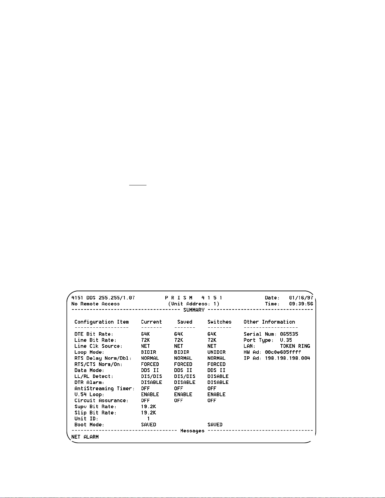
The Summary screen (Figure 3-16) is a
display-only
screen
summarizing the unit configuration including stored memory and switch settings. The current column displays the
current unit configuration. The saved column displays the
configuration stored in memory. The switches column displays all the configuration switch settings.
Figure 3-16 Summary Screen
Configuration 3-9PRISM 4151
Page 22

Utilities
The Utilities screen (Figure 4-23) handles the functions
described in the following paragraphs.
Element ID
(29 characters in length) identifying the unit to the device
receiving the alarm notification messages. This ASCII
string is also displayed at the top of all terminal interface
screens.
Unit Address:
Set Time
using the 24- hour HH :MM :SS format. For example, 3:45
AM is entered as 03:45:00 and 3:45 PM is entered as
15:45:00.
Set Date
using the MM/DD/YY format. For example, July 4, 1996 is
entered as 07/04/96.
The PRISM 4151 is Year 2000 date compliant.
All date related functions for the year 2000 and
after will operate without d iscrepancies or in terruptions.
New Password
to 10 characters. An empty string (carriage return only) may
be entered to disable the password feature. After <return> is
pressed, the new password is activated and is no longer visible. Therefore, type carefully when entering a new password and verify before pressing <return>. When the
terminal interface is exited and later reactivated, this password must be entered exactly to gain access. If the wrong
password is entered, the following message will appear:
Incorrect Password; Please Enter Again.
: This field allows the entry of an ASCII string
The unit address between 1 and 250.
: The current time may be entered in this field
: The current date may be entered in this field
: This field allows entry of a password of up
Do not exit the terminal interface
program until the password procedure is fully understood. If a password
has been specified, it must be typed
exactly to reenter the program.
If you program a password and later forget it, contact
TxPORT Technical support for a one-time backdoor password.
Store Parameters to EEPROM:
This command causes the
unit to store all user-selectable parameters into non-volatile
memory. These settings then become the
saved
configura-
tion which can be loaded at power-up.
This command causes the unit to
restart and will interrupt network
traffic. Pressing <RETURN> on this field
to activate the command brings up the
following warning:
ARE YOU SURE? - THIS WILL INTERRUP T DDS DA TA
(NO!) (YES)
Maintenance Reset
: This field will clear all user selectable
parameters, performance registers, passwords, and alarms
but saves the IP Addr ess. All alarm th reshold parame ters are
set to default values. These settings are then written to nonvolatile memory as the
configuration.
saved
This command causes the unit to
restart and will interrupt network
traffic. Pressing <RETURN> on this field
to activate the command brings up the
following warning:
ARE YOU SURE? - THIS WILL INTERRUP T DDS DA TA
(NO!) (YES)
3-10 Configuration
Figure 3-17 Utilities Screen
PRISM 4151
Page 23

Factory Reset:
Clears all user selectable parameters
including the IP Address.
To exit this screen without performing the reset function,
press <return>with NO selected. To proceed with the reset
function, move the cursor to YES and press <return>.
The reset operation sets all parameters to the
factory default settings and zeros all performance registers.
This command causes the unit to
restart and will interrupt network
traffic. Pressing <RETURN> on this field
to activate the command brings u p the following warning:
ARE YOU SURE? - THIS WI LL INTERRU P T DDS DATA
(NO!) (YES)
Configuration 3-11PRISM 4151
Page 24

3-12 Configuration
PRISM 4151
Page 25

4. Testing
TRANSPORT
®
This chapter describes hardware and software testing procedures and responses for the PRISM 4151.
Hardware Testing
The PRISM 4151 front panel (Figure 4- 1) has five LED
indicators and two control buttons from which you can perform basic unit testing.
Front Panel LEDs
Five front panel LEDs allow a visual identification of the
test results and alarms. These LEDs are: TEST, LOOP,
NET, ALARM, and POWER.
TEST
This LED flashes amber when the unit is transmitting loop
or unloop code. It is gr een continuously when BERT is on
with no errors. It is red when the BERT is on and is receiving errors or is out of pattern sync.
LOOP
This amber LED lights continuously when the unit is in any
loop condition.
NET
This LED is green when th e unit is in frame sync and does
not detect a Loss of Signal. It is red when the unit is out of
frame sync and/or detects Loss of Signal.
TEST
When this button is pushed once, the unit transmits V.54
loop code sequence out to the network. The indicator blinks
amber during transmission of the loop code.
At completion of the loop pattern, 511 BERT pattern is
transmitted toward the network. The received pattern is
compared and if the pattern is received error free, the TEST
indicator remains green. If pattern errors are detected, the
TEST indicator turns red for one second for each errored
second. Therefore, if five errored seconds are received, the
indicator will remain red for five seconds. The DTE port is
looped back toward the DTE during the test.
If the TEST button is pushed again, the unit transmits V.54
loop down code and returns to normal operating mode. The
TEST indicator is then turned off.
LOOP
When this momentary push button is pushed once, the unit
activates a line loopback, looping the network receive data
back to the network, and looping the data from the DTE
ports back to the DTE. The TEST indicator is illuminated
while the unit is in loop. If pushed again, the unit clears the
loop and turns off the LOOP indicator.
For additional information concerning test and
loop options, refer to the section Software Configurat ion on page 3-2.
ALARM
Red LED lights continuously when the unit is in an active
alarm condition.
POWER
Green LED lights continuously when power is applied to the
unit.
Front Panel Buttons
Two front panel buttons allow you to perform loopback
tests. The two buttons are: TEST and LOOP.
PRISM 4151
Figure 4-1 Front Panel Controls and Indicators
Software Testing
When in-depth testing is necessary, you can use the PRISM
4151 Maintenance screen (Figure 4- 2 on page 4 - 2) to perform loop tests and/or BERT functions on the DDS circuit.
You can activate and clear loops and the BERT tester. BERT
is performed by using on -board test facilities. No other test
equipment is needed. Some of these tests may also be activated by the front panel push buttons as described in Hardware Testing on page 4-1.
TEST LOOP
ALARMNETLOOPTEST
POWER
Testing 4-1PRISM 4151
Page 26

Clear Tests:
Pressing <return> on this field clears all local
tests and any line loops that have been initiated.
Clear Alarms
near end alarms to be cleared.
: The type of loop is chosen by toggling the <space-
Loop
: Pressing <return> on this field causes all
bar> and is executed by pressing <return>. Options include
LOCAL
, V. 54, a nd FAR V. 54. L ocal a nd V.54 generate near
end loops. Far V.54 generates a V.54 loop at the far end.
Unloop:
Pressing <return> takes down the specified loop
from the currently selected port. The type of loop is chosen
by toggling the <spacebar> and is executed by pressing
<return>. Options include LOCAL
Loop Mode
: Options include BIDIRECTIONAL
, V.54, and FAR V.54.
and UNIDIRECTIONAL. When set to Unidirectional, the NET
receive data is looped back to the NET as NET transmit data
and continues to pass through the data port to the DTE.
Transmit data from the DTE is terminated. When set to
Bidirectional, the NET receive data is looped back to the
NET as NET transmit data. Transmit data from the DTE is
looped back through the data port as receive data to the
DTE.
Line Loop:
Occurs at the DDS network interface and activated by the reversal of the simp lex, 20 mA s ealing cu rrent.
This is a unidirectional loop that ignores the CSU/DSU
transmit data and retransmits the received DDS data.
Receive data is unaffected and circuits DSR and CD are
forced OFF.
Line Loop
DTE
NET
Occurs at the DDS network interface. In DDS I
Data Loop
:
mode, the data loop is activated when the CSU/DSU
receives alternating loop codes in the network receive data
stream. Technically, it is activated by the receipt of at least 4
consecutive loop commands and remains looped as long as
each 3rd pattern byte is the loop command. It returns to normal operation after at least 4 pattern bytes that are not the
loop command. This is a unidirectional loop that retransmits
the CSU/DSU received data on the CSU/DSU transmit data
including the remapped loop code. Receive data is unaffected (but includes the modified loop codes) and circuits
DSR and CD are OFF.
In DDS II mode, the data loop is activated when the latching
loopback sequence is received. The sequence consists of 35
or more TIP bytes, 35 or mor e L SC bytes, 10 0 or m ore L BE
bytes, 32 or more FEV bytes. Latching loop is deactivated
when 31 or more TIP bytes are received.
Data Loop
V.5 4 L oo p
V.5 4 L oop:
Occurs at the DDS network interface and is
DTE
NET
activated upon receipt of inband V.54 loop codes for at least
two seconds followed by all ones in the network receive
data stream. This loop is unidirectional and returns the
CSU/DSU receive data to the CSU/DSU transmit data, and
subsequently the DDS transmit data. Receive data is unaffected and DSR and DCD are forced OFF.
Local Loop:
Bidirectional and occurs at the DDS network
interface. It returns the DDS receive data to the DDS transmit line and the CSU/DSU transmit data to the CSU/DSU
receive data output.
4-2 Testing
Figure 4-2 Element Maintenance Screen
PRISM 4151
Page 27

Local Loop
Activate Remote Access:
DTE
Pressing <return> on this field
NET
initiates communication with another PRISM 4151 DDS
unit at the far end of the network link.
The near unit will transmit an activation signal to the far end
unit for five seconds. At the end of this period, both units
should be in remote access mode. While in this mode, the
DCD and DSR signals to the DTE interface are FALSE and
the transmit data from the DTE is not transmitted to the network. The command field also changes to DEACTIVATE
REMOTE ACCESS.
While Remote Access is active, the far end type/revision
information should be displayed in the upper left corner of
each screen. Also on each screen, a field labeled
with selectable values of
Near
and
appears. Pressing
Far
Element
<return> on this field activates the user interface for the
selected element.
To terminate Remote Access, press <return> on the DISABLE REMOTE ACCESS field. Both units will immediately return to normal operation.
During Remote Access, either unit will return to
normal operation if communication with the far
end is lost for 30 seconds.
BERT:
These fields control the Bit Error Rate Test feature.
BERT is performed on the NET interface and preempts user
data.
Te st L en gt h :
Defines the run-time of test pattern generation and error accumulation. The choices are [15 min], [30
min], [60 min], [24 Hour], and [Continuous
Pattern Sync
: This field displays the current state of pat-
].
tern sync during a test. If no test is in progress, NO TEST is
displayed. If a test is active, but the receiver is not in pattern
sync, NO SYNC is displayed. If the receiver is in pattern
sync, IN SYNC is displayed.
Elapsed Time:
Displays the amount of time elapsed since a
timed test began or, if completed, the total test time.
Bit Errors
: Displays the total number o f bit errors detected
since the test began or since error statistics were cleared (Up
to a maximum number of 999,999).
Errored Sec onds
: This field displays the number of asynchronous errored seconds that have been detected since the
test began or since error statistics were last cleared. This
parameter includes bit error seconds and sync loss seconds.
% EFS
: This ratio is derived from the number of error free
seconds divided by the number of seconds accumulated in
Elapsed Time.
Start Test:
Pressing <return> with the cursor on this field
starts the selected test pattern. TEST IN PROGRESS
appears once the test has started. To end the test, press
<return> on STOP TEST.
Reset Errors:
Pressing <return> with the cursor on this
field causes the test error results to be cleared to zero.
NET/DTE Status
: These two fields display the fault status
of the network and the far end DTE. They indicate current
fault conditions. They do not indicate that alarm thresholds
are exceeded. Status indications are described in NET/DTE
Status: These two fields display the fault status of the network and the T1 DTE. They indicate current fault conditions. They do not indicate that alarm thresholds are
exceeded. Status indications are described in Table 4-I.
Table 4-I Status Indications
Status Description
------- No status is available
OK No errors are currently detected.
LOS A loss of signal condition exists.
OOF An out of frame condition exists or OOF codes are
received.
OOS Out of Service codes are received.
DTR DTR from the DTE device is false.
Near Loops
Far Loops
: Displays the loop status of the near element.
: Displays the loop status of the far element.
Testing 4-3PRISM 4151
Page 28

4-4 Testing
PRISM 4151
Page 29

5. Operation
This chapter describes the alarm types and status for the
PRISM 4151.
Interface Start-up
Once a compatible terminal is properly connected to the
unit, you can start a terminal interface session by sending a
BREAK command to the unit (or by pressing <return> four
times). If a password has been previously establish, you
must enter the correct password to continue the session.
password is case- s ensitive.
word, note the date and time shown on your screen and contact TxPORT Technical Support. You can establish a
password through the Utilities screen on page 3-10.
Once a valid password has been entered, the Main Menu
screen is displayed. If you are unfamiliar with the PRISM
4151 interface, commands, and menu structure, refer to
Appendix A,
concerning the menu structure and operator commands.
Terminal Interface
If you do not enter a keystroke for
10 minutes, the terminal interface
automatically logs off.
If you have forgotten your pass-
, for specific information
The
Alarms
The Alarms screen (Figure 5-3) allows you to view the current alarm status of the network and the DTE lines.
NET Alarms
ment’s current network signal alarm state (Table 3-J).
: These status lines display the selected ele-
Alarms are determined by the selectable thresholds in Alarm
Configuration on page 3-5.
Table 3-J NET Alarm Indicators
Alarm Description
------- No status is available
None No alarm threshold has been exceeded, although
errors may exist which do not exceed thresholds.
LOSS The Loss Of Signal Seconds thresho ld is e xceed ed.
OOFS The Out Of Frame Seconds threshold is exceeded.
OOSS The Out Of Service Seconds threshold is exceeded.
DTE Alarms
ment’s current DTE signal alarm state (Table 3-K). Alarms
are determined by the selectable thresholds in Alarm Configuration on page 3-5.
: These status lines display the selected ele-
Figure 5-3 Alarms Screen
Operation 5-1PRISM 4151
Page 30

Table 3- K DTE Alarm Indicators
Alarm Description
None DTR on DTE interface is true, or the alarm has
been disabled.
DTR DTR on DTE interface is false.
Selectable thresholds in the Alarm Parameters screen and
the DTR Alarm may be enabled or disabled for the ports in
the Port Parameters screen.
(alarm status)
: The main body of the Alarms screen shows
the current count for parameters that may be used to trigger
an alarm.
The Current column displays the consecutive seconds during which the error condition has existed.
The Threshold column displays the values set in the Alarm
Configuration screen (page 3 -5). Parameters having a current value equal to or greater than its non-zero threshold
generates an alarm. Any parameter with a threshold value of
zero is disabled from generating alarms. An alarm is
declared when the current value of any parameter exceeds
its non-zero threshold.
The parameters show n on the A larms screen are
updated at approximately five second intervals.
Reset Alarm Registers
: Pressing <return> on (RESET)
zeros the value of all Current alarm parameters.
5-2 Operation
PRISM 4151
Page 31

A.Terminal Interface
This chapter describes the screens structure and menu controls for the TxPORT PRISM 4151 terminal interface. The
interface is a firmware application program embedded
inside the unit.
It requires an ANSI compatible VT100 terminal (ASCII), or
a computer running an ANSI terminal emulation program.
The terminal interface uses ASCII BREAK and ESCAPE
functions, which are implemented differently with the various terminal emulation programs.
Screen Components
Terminal interface screens have several components common to all screens (Figure A- 4).
Device Type and Revision:
PRISM 4151) and the revision control numbers are shown
in the upper left corner. The first number is the hardware
revision and the second number is the software revision.
Information is displayed for the near end unit (connected
directly to the terminal) on the t op line, and for the far end
unit (connected to the network T1 interface) on the second
line. Far end information is displayed only wh en activated,
otherwise,
information when contacting the factory with inquiries.
Date/Time:
plays the current date and time. The setting of these functions
is described in the section entitl ed Ut ili tie s on page 3-10.
No Remote Access
The top right corner of the terminal scree n dis-
The device type (such as
is displayed. Refer to this
Element ID:
ID is displayed. Refer to the section entitled Management
Ports on page 3-8 for information on the Element ID.
Menu Title:
general classification of functions currently accessible by
the user (such as MAIN or PERFORMANCE).
Messages:
bottom of the screen.
Below the header (PRISM 4151), the Element
The menu title (third line, center) den otes the
Diagnostic messages may be displayed at the
Cursor Controls
The terminal interface utilizes a highlighted cursor to make
selections from menus and select fields within screens to be
operated on. The cursor is moved in different ways, depending on the terminal emulation program used. Most programs
allow use of the <tab> and <shift- tab> keys. Others allow
use of the arrow keys. Once a field is highlighted, it is
manipulated as described in Section .
For keyboards which do not have these standard keys or
have only some of them, an alternate set of cursor control
commands is provided. Each command is performed by
pressing a letter key while holding down the <Ctrl> key.
Figure A-4 Terminal Interface Layout
Terminal Interface A-1PRISM 4151
Page 32

Alternate commands may be freely mixed with the keyboard
Alarms
MAIN
MENU
Log
Off
LogOnMaintenance
Configuration
Utilities
DTE Port Parameters
Alarm Parameters
TCP/IP Parameters
SNMP Parameters
Management Ports
Summary
Figure A-5 Terminal Interface Menu Structure
DDS Network Parameters
commands at your discretion.
Table A-L Keyboard / Alternate Commands
Keyboard Command Alternate Command
< left arrow > < Ctrl - S >
< right arrow > < Ctrl - D >
< up arrow > < Ctrl - E >
< down arrow > < Ctrl - X >
< backspace > < Ctrl - H >
< delete > < Ctrl - Z >
Field Types
Each screen is made up of fields. The two basic field types
are user-selectable and display-only. If the highlighted cursor can be moved to a field, it is a user selectable field. All
other fields are for display only. User selectable fields allow
for changes to be made or commands to be executed.
Fields without brackets or parenthesis are display-only.
They cannot be changed on the screen. Most user selectable
fields are enclosed in brackets or parenthesis and are
described in the following paragraphs.
Fields enclosed in brackets [ ] offer the user a list of selections from which to choose. The selections may be toggled
by pressing the <spacebar>. Each time it is pressed, a new
item appears. When the appropriate choice is displayed,
press <return> to select it.
Fields enclosed in parenthesis ( ) are manipulated by one
of the following two methods:
1. Pr essing <return> on such fields as (R eset) and (Star t
Test) simply execute the function.
Menu Structure
The Main Menu screen lists the functional user accessible
menus. To activate a menu, highlight the desired selection
and press <return>. To exit this or any subsequent menu,
press <esc>. If the Main Menu is exited, the terminal interface program terminates. This is a valid way to end a session. If any other menu is exited, the previous screen is
returned. The menu structure (Figure A- 5) shows all the
screens accessible from the Main Menu.
If you do not enter a keystroke for
10 minutes, the terminal interface
logs off automatically.
2. The most common type of field in parenthesis accepts
typed input in the form of letters and / or numbers. Typing characters when the field is highlighted causes the
current entry to be replaced with the new characters. To
edit an existing entry rather than replace it, press the
<right arrow> key to move the cursor to the point that
needs editing. Characters may then be inserted or
deleted. Typed data is always inserted rather than typed
over. If the field is full, though, at least one character
must be deleted to add another.
Many fields of this type may also be toggled by pressing the
<spacebar>. Other fields are range checked, where the user
is not allowed to exit with an illegal value set.
Any screen may be redisplayed (or refreshed) by
pressing <Ctrl - U>.
Terminal Interface A-2
PRISM 4151
Page 33

B.Pinout Tables
This appendix displays the pinout assignments for each port
and option on the rear of the PRISM 4151.
LAN Port - Ethernet
Pin Signal Name
1 D ata Out
2 D ata Out
3 Data In
6 Data In
LAN Port - Token Ring
Pin Signal Name
3 D ata Out
4 Data In
5 Data In
6 D ata Out
SLIP / SUPV Port - PC
Pin Signal Name DTE Pin
1 DTR Out DCD 1
2 RTS Out CTS 8
3 Frame Gnd Frame Gnd 5
4 Data Out RXD 2
5Data In TXD 3
6 Signal Gnd Signal Gnd NC
7CTS In RTS 7
8 DCD In DTR 4
Net
Pin Signal Name
1 Data Out (Tip)
2 Data Out (Ring)
3-6 Not Used
7 Data In (Tip)
8 Data In (Tip)
Data Port
Signal Name V.35 Acronym
Frame Ground A FG
Transmit Data P, S TD
Receive Data R, T RD
Request to Send C RTS
Clear to Send D CTS
Data Set Ready E DSR
Signal Ground B SG
Data Carrier Detect F DCD
Transmit Clock Y, AA TXC
Receive Clock V, X RXC
Local Loopback J LL
Data Term Ready H DTR
Remote Loopback BB RL
Terminal Timing U, W TT, EXC
SLIP / SUPV Port - Modem
Pin Signal Name DCE Pin
1 DTR Out DTR 20
2 R TS Out RTS 4
3 Frame Gnd Frame Gnd 1
4 Data Out TXD 2
5 Data In RXD 3
6 Signal Gnd Signal Gnd 7
7 CTS In CTS 5
8 DCD In DCD 8
Pinout Tables B-1PRISM 4151
Page 34

B-2 Pinout Tables
PRISM 4151
Page 35

C.SNMP Ag e nt
This unit has an embedded SNMP agent which can be
accessed either through the built in SLIP interface or the
optional Network Interface Card (NIC). The NIC can either
be an Ethernet or Token Ring interface. With these interfaces, you can gain access to the PRISM 4151 through TELNET or SNMP. The TELNET session is simply a
connection to the user interface of the unit.
SNMP access to the unit is limited to Management Information Bases (MIBs) supported by the embedded SNMP agent.
The SNMP agent supports MIB-II (RFC 1213). This appendix describes in detail how the embedded SNMP agent conforms to the RFC.
RFC 1213
This RFC defines the MIB-II specif i cation .
systemTable
sysDescr:
This entry is a textual description of the entity. It should
include the full name and version identification of the system's hardware type, software operating-system, and networking software. It is mandatory that this only contain
printable ASCII characters. For the PRISM 4151, this value
returns the string
sysObjectID:
The vendor's authoritative identification of the network
management subsystem contained in the entity. This value
is allocated within the enterprises subtree (1.3.6.1.4.1) and
provides an easy and unambiguous means for determining
‘what kind of box' is being managed. For example, if vendor ‘Flintstones, Inc.' was assigned the subtree
1.3.6.1.4.1.4242, it could assign the identifier
1.3.6.1.4.1.4242.1.1 to its ‘Fred Router'. For the PRISM
4151, this value returns the Object Identifier of
1.3.6.1.4.1.254.1.1
sysUpTime:
The time (in hundredths of a second) since the network
management portion of the system was last re-initialized.
sysContact:
The textual identification of the contact person for this managed node, together with inform ation on how to contact this
person. The string defaults to ‘no system contact.’
sysName:
An administratively-assigned name for this managed node.
By convention, this is the node's fully-qualified domain
name. The default is ‘no system name’
sysLocation:
(read-only)
TxPORT SNMP Agent
(read-only)
.
(read-only)
(read-w rite)
(read-w rite)
(read-write)
.
The physical location of this node (e.g.,‘telephone closet,
3rd floor'). The default is ‘no system location’
sysServices:
(read-only)
A value which indicates the set of services that this entity
primarily offers. The value is a sum. This sum initially
takes the value zero. Then, for each layer, L, in the range 1
through 7, that this node performs transactions for, 2 raised
to (L - 1) is added to the sum. For example, a node which
performs primarily routing functions would have a value of
(3-1)
4 (2
cation services would have a value of 72 (2
). In contrast, a node which is a host offering appli-
(4-1)
+ 2
(7-1)
Note that in the context of the internet suite of protocols,
values should be calculated accordingly:
1 physical (e.g.,repeaters)
2 datalink/subnetwork (e.g., bridges)
3 internet (e.g., IP gateways)
4 end-to-end (e.g., IP hosts)
7 applications (e.g., mail relays)
For systems including OSI protocols, layers 5 and 6 may
also be counted. The PRISM 4151 returns a value of 72 representing a host offering application services.
ifTable
ifNumber:
The number of network interfaces (regardless of their current state) present on this system. There are always a minimum of 3 (SLIP, Network - DDS, and Port 1). The optional
interface is an NIC (Ethernet or Token Ring) card.
ifIndex:
A unique value for each interface. Its value ranges between
1 and the value of ifNumber. The value for each interface
must remain constant at least from one re-initialization of
the entity's network management system to the next re-initialization.
ifDescr:
A textual string containing information about the interface.
This string should include the name of the manufacturer, the
product name and the version of the hardware interface.
(read-only)
(read-only)
With NIC Without NIC
1
- SLIP
2
- NIC
3
- DDS
4
- DTE Port
1
- SLIP
2
- DDS
3
- DTE Port
(read-only)
‘SLIP Interface’
‘Ethernet NIC’
face
- returned for the SLIP Interface
- returned for the NIC, for Ethernet inter-
).
SNMP Agent C-1PRISM 4151
Page 36

ifType:
‘Token Ring NIC’
‘DDS Network Interface’
face
‘DDS DTE RS-232/V.35 Port’
(read-only)
- returned for the NIC, for Token Ring
- returned for the DDS inter-
- returned for DTE Port
The type of interface, distinguished according to the physical/link protocol(s) immediately ‘below' the network layer
in the protocol stack.
ifMtu:
other(1)
regular1822(2)
hdh1822(3)
ddn-x25(4)
rfc877-x25(5)
ethernet-csmacd(6) iso88023-csmacd(7)
iso88024-tokenBus(8)
iso88025-tokenRing(9) iso88026-man(10)
starLan(11)
proteon-10Mbit(12)
proteon-80Mbit(13)
hyperchannel(14)
fddi(15)
lapb(16)
sdlc(17)
ds1(18)
e1(19)
basicISDN(20)
primaryISDN(21)
propPointToPointSerial(22) ppp(23)
softwareLoopback(24)
eon(25)
ethernet-3Mbit(26)
nsip(27)
slip(28)
ultra(29)
ds3(30)
sip(31)
frame-relay(32)
(read-only)
- none of the following
Ethernet NIC
Token Ring NIC
- european equiv. of T-1
- proprietary serial
Port 1
- CLNP over IP [11]
- XNS over IP
- generic SLIP
- ULTRA technologies
- T-3
- SMDS
The size of the largest datagram which can be sent/received
on the interface, specified in octets. For interfaces that are
used for transmitting network datag rams, this is the size of
the largest network datagram that can be s ent on the interface.
296
- returned for the SLIP Interface
1500
- returned for the NIC interface (if Ethernet)
2000
- returned for the NIC interface (if Token Ring)
0
- returned for the DDS and Port 1 interfaces
ifSpeed:
(read-only)
An estimate of the interface's current bandwidth in bits per
second. For interfaces which do not vary in bandwidth or
for those where no accurate estimation can be made, this
object should contain the nominal bandwidth
9600
- returned for the SLIP Interface at 9600 baud
19200
- returned for the SLIP Interface at 19200 baud
38400
- returned for the SLIP Interface at 38400 baud
56000
- returned for the SLIP Interface at 56000 baud
10000000
4000000
16000000
Mbps)
ifPhysAddress:
- returned for the NIC (if Ethernet)
- returned for the NIC (if Token Ring at 4 Mbps)
- returned for the NIC (if Token Ring at 16
(read-only)
The interface's address at the protocol layer immediately
‘below' the network layer in the protocol stack. For interfaces which do not have such an address (e.g., a serial line),
this object should contain an octet string of zero length. One
exception is the NIC interface which returns the physical
address of the unit
ifAdminStatus:
(read-write)
The desired state of the interface. The testing(3) state indicates that no operational packets can be passed. For the
PRISM 4151, you do not have write permission.
up(1)
- Ready to pass packets
down(2)
testing(3)
ifOperStatus:
- In test mode
(read-only)
The current operational state of the interface. The testing(3)
state indicates that no operational packets can be passed.
up(1)
- Ready to pass packets. This value is returned if
th e inte r fa c e is a c t iv e, a n d do e s not h av e a te s tin g s ta t u s.
down(2)
testing(3)
DDS and DTE interfaces if the interface has a test loop or
BERT active.
IfLastChange:
- Returned if the interface is not enabled
- In test mode. This value is returned for the
(read-only)
The value of sysUpTime at the time the interface entered its
current operational state. If the current state was entered
prior to the last re-initialization of the local network management subsystem, then this object contains a zero value.
C-2 SNMP Agent
PRISM 4151
Page 37

The PRISM 4151 returns the time in hundredths of a second
since the interface was changed, or reset
DDS
The TxPORT enterprise DDS MIB contains the following
objects that allow unit management from any S NMP manag er.
DDS Network Objects
ddsNetRate:
This object allows you to verify or set the identifier of the
current DDS network rate. Only the
ddsNetRate64 000
controlled by the
changed independently.
ddsNetMode:
This variable describes mode in which data is being sent
from the DDS unit back towards the network. Changing the
value of this variable can cause a loss of remote communications.
ddsNetModeNormal(1)
ddsNetModeProprietary(2)
DDS network is in a pr oprietary mode to al low for remo te
communications, rate adaption, and SYNC to ASYNC
modes.
ddsNetMode64KClearChannel(3)
DDs-II, where the line rate is 72K, the data rate is 64K, and
there is no secondary channel.
ddsNetSendCode:
This variable describes what type of test code is being sent
from the DDS unit back towards the network.
ddsNetSendNoCode(1)
ddsNetSendOtherTestPattern(2)
stress pattern than 511
ddsNetSend511Pattern(3)
toward the network
ddsNetLoopConfig:
This variable allows you to set or view the current loop state
of the DDS network interface.
(read-write)
apply to the PRISM 4151. Both rates are
ddsNetMode
ddsNetRate2400
ddsNetRate 4800
ddsNetRate 9600
ddsNetRate 19200
ddsNetRate38400
ddsNetRate56000
ddsNetRate64000
(read-write)
(read-write)
(read-write)
ddsNetNoLoop(1)
ddsNetRate56000
setting and cannot be
- 2400bps
- 4800bps
- 9600bps
- 19200bps
- 38400bps
- 56000bps
- 64000bps
- normal data mode of operation.
- Data being sent out on the
- A special case of
- Normal data mode of operation
- Sending some other
- Sending 511 stress pattern
- Normal data mode of operation
and
ddsNetLocalLoop(2)
DDS network switch activated loop
ddsNetLineLoop(3)
DDS network sealing current activated loop
ddsNetOtherLoop(4)
active
ddsNetFarEndLineLoop(5)
a line loop active
ddsNetStatus:
(read-only)
- Data is looped back toward the
- Data is looped back toward the
- Other loop than listed above is
- Far end unit currently has
Reports current operational status of the network interface
ddsNetNoAlarm(1)
rent alarms
ddsNetLOS(2)
nal
ddsNetOOS(3)
Out Of Service codes
ddsNetOOF(4)
Frame condition
ddsNetTimingSource:
- DDS network interface has no cur-
- DDS network interface has Loss Of Sig-
- DDS network interface is receiving
- DDS network interface has Out Of
(read-write)
Allows you to select or verify the current timing source for
the DDS network interface.
ddsNetTimingNet(1)
DDS network interface timing
ddsNetTimingInt(2)
network interface
ddsNetTimingDTE(3)
device for network interface timing
ddsNetRemComm:
- Unit depend ent upon network fo r
- Unit supplying timing for DDS
- Unit dependent upon DTE
(read-)only
Reports status of the remote communications link
ddsNetRemCommEnabled(1)
tions can be carried out end to end
ddsNetRemCommDisab led(2)
tions are not allowed
ddsNetRemCommNotAvailable(3)
support remote communications
ddsNetCircuitAssur:
(read-write)
- Remote communica-
- Remote communica-
- This unit does not
Allows you to enable or check setting of the circuit assurance option. Circuit Assurance does not apply to the DDS-II
operating mode.
ddsNetCircuitAssurEnabled(1)
enabled and the integrity of the DDS loop will be maintained
ddsNetCircuitAssurDisabled(2)
disabled
ddsNetCircuitAssurNotAvailable(3)
support Circuit Assurance
ddsNetAntiStrTimer:
(read-wr ite)
- Circuit Assurance is
- Circuit Assurance is
- This unit does not
This variable describes the current setting for the anti
streaming timer .
SNMP Agent C-3PRISM 4151
Page 38

ddsNetAntiStrTimerOff(1)
ddsNetAntiStrTimer10(2)
set to 10 seconds
ddsNetAntiStrTimer30(3)
set to 30 seconds
ddsNetAntiStrTimer60(4)
set to 60 seconds
ddsNetLoopMode:
(read-write)
- AntiStreaming Timer is off
-
AntiStreaming Timer is
-
AntiStreaming Timer is
-
AntiStreaming Timer is
Allows you to review or set Loop Mode to unidirectional or
bidirectional
ddsNetLoopModeUnidirectional(1)
V54 loops will be unidirectional Local loop will be bidirectional
ddsNetLoopModeBidirectional(2)
bidirectional
- Line, Data, and
- All loops will be
DDS DTE Objects
ddsDteRate:
Allows you to verify or select the DDS DTE data rate. Only
the
ddsDteRate56000
PRISM 4151. Both rates are controlled by the
setting and cannot be changed independently.
ddsDteFormat
This variable describes the current operations format of the
DTE interface. Only the
PRISM 4151.
ddsDteParity:
Allows you to verify or select parity for the DTE interface.
This variable is only valid when the DTE Mode is set to
ASYNC. For the PRISM 4151, the value always returns
ddsDteParityNotAvail
(read-write)
and
ddsDteRate64000
apply to the
ddsNetMode
ddsDteRate2400
ddsDteRate4800
ddsDteRate9600
ddsDteRate19200
ddsDteRate38400
ddsDteRate54000
ddsDteRate56000
ddsDteRate57600
ddsDteRate62000
ddsDteRate64000
- 2400bps
- 4800bps
- 9600bps
- 19200bps
- 38400bps
- 54000bps
- 56000bps
- 57600bps
- 62000bps
- 64000bps
(read-write)
ddsDteFormatSync
ddsDteFormatSync(1)
operate in Synchronous clocking fo r m at
ddsDteFormatAsync(2)
to operate in the Asynchronous clocking format
ddsDteFormatNotAvail(3)
format is not available
- DTE interface is currently set to
- DTE interface is currently set
- DTE interface operating
applies to the
(read- write)
. This value cannot be modified.
ddsDteParityNone(1)
no parity bit checking or generation
- DTE interface is currently set for
ddsDteParityOdd(2)
odd parity
ddsDteParityEven(3)
even parity
ddsDteParityMark(4)
mark parity
ddsDteParitySpace(5)
for space parity
ddsDteParityNotAvail(6)
interface is not available.
ddsDteStopBit:
(read- write)
- DTE interface is currently set for
- DTE interface is currently set for
- DTE interface is currently set for
- DTE interface is currently set
- Parity setting on the DTE
Allows you to verify or set the stop bit setting for the DTE
interface. This variable is only valid when the DTE interface
is set to ASYNC. For the PRISM 4151, the value always
returns
ddsDteStopBitNotAvail
. This value cannot be modi-
fied .
ddsDteStopBit1(1)
ate in the ASYNC mode with 1 stop bit
ddsDteStopBit2(2)
ate in the ASYNC mode with 2 stop bits
ddsDteStopBitNotAvail(3)
available. The DTE interface is probably configured for
synchronous operation.
ddsDteSendCode:
- DTE interface is configured to oper-
- DTE interface is configured to oper-
- Stop bit information is not
(read- write)
Allows you to start or verify the setting of the DTE BERT.
This variable describes what type of test code is being sent
from the DDS unit back towards the DTE. For the PRISM
4151, only the
ddsDteSendNoCode
applies. Other values are
accepted but not acted upon.
ddsDteSendNoCode(1)
ddsDteSendOtherPattern(2)
pattern than 511
ddsDteSend511Pattern(3)
toward the DTE
ddsDteLoopConfig:
(read- write)
- Normal data mode of operation
- Sending some other stress
- Sending 511 stress pattern
Allows you to set a DTE loop or verify the status of a DTE
loop
ddsDteNoLoop(1)
ddsDteV54Loop(2)
DDS network and toward the DTE l oop activated via
V.54 loop codes
ddsDteDataLoop(3)
DTE loop activated via data loop code received from
the network
ddsDteOtherLoop(4)
other than one of the above listed loops active
ddsDteFarEndV54Loop(5)
loop current on it's DTE interface
ddsDteStatus:
(read- on ly)
- Normal data mode of operation
- Data is looped back toward the
- Data is looped back toward the
- DTE interface has some loop
- The far end unit has a V.54
Reports the current operations status of the DTE interface
C-4 SNMP Agent
PRISM 4151
Page 39

ddsDteNoAlarm(1)
alarms
ddsDteDtrAlarm(2)
declared a loss of DTR alarm
ddsDteInterfaceType:
- DTE interface has no current
- DTE interface has currently
(read- only)
Reports the DTE interface type being used
ddsDteInterfaceV35(1)
ddsDteInterface232(2)
ddsDteInterfaceOther(3)
other than listed above
ddsDteInterfaceNotAvail(4)
available
ddsDteV54Loop:
(read- write)
- DTE interface is a V.35
- DTE interface is a RS232
- DTE interface is something
- DTE interface type is not
Allows you to select or verify the operational state of the
V.54 option
ddsDteV54LoopEnabled(1)
respond to V.54 loop codes
ddsDteV54LoopDisabled(2)
to V.54 loop codes
ddsDteRtsCtsDelay:
(read- write)
- The unit will currently
- The unit will not respond
Allows you to verify or select the delay used in the transition time on RTS and CTS. For the PRISM 4151, only the
ddsDteRtsCtsDelayNor mal
and
ddsDteRtsCtsDelayLong
option are valid.
ddsDteRtsCtsDelayOff(1)
ddsDteRtsCtsDelayNormal(2)
amount based on the data rate and the hardware
ddsDteRtsCtsDelayLong(3)
from the normal delay
ddsDteRtsCTSDelayUserDefined(30)
user defined to some other value, when this value is set
the delay is se t to 30ms
ddsDteRtsStatus:
(read- only)
- Delay is turned off
- Delay is a normal
- Delay is generally do uble d
- Delay has been
Reports the current status of the RTS control lead
ddsDteRtsStatusHigh(1)
active HIGH state
ddsDteRtsStatusLow(2)
active LOW state
ddsDteCtsStatus:
(read- only)
- RTS control lead is in the
- RTS control lead is in the
Reports the current status of the CTS control lead
ddsDteCtsStatusHigh(1)
active HIGH state
ddsDteCtsStatusLow(2)
active LOW state
ddsDteDcdStatus:
(read- only)
- CTS control lead is in the
- CTS control lead is in the
Reports the current status of the DCD control lead
ddsDteDcdStatusHigh(1)
active HIGH state
- DCD control lead is in the
ddsDteDcdStatusLow(2)
active LOW state
ddsDteDtrStatus:
(read- only)
- DCD control lead is in the
Reports the current status of the DTR control lead
ddsDteDtrStatusHigh(1)
active HIGH state
ddsDteDtrStatusLow(2)
active LOW state
ddsDteDsrStatus:
(read- only)
- DTR control lead is in the
- DTR control lead is in the
Reports the current status of the DSR control lead
ddsDteDsrStatusHigh(1)
active HIGH state
ddsDteDsrStatusLow(2)
active LOW state
ddsDteDsrControl:
(read-write)
- DSR control lead is in the
- DSR control lead is in the
Allows you to review and configure the DTE DSR lead (Circuit 107/CC)
ddsDteDsrControlTestOff(1)
the unit is in test
ddsDteDsrControlForcedOn(2)
of any unit condition
ddsDteDcdControl:
(read-write)
- DSR is on except when
- DSR is on regardless
Allows you to review and configure the DTE DCD lead
(Circuit 109/CF).
ddsDteDcdControlIdleOff(1)
the unit is receiving Idle Code from the network.
ddsDteDcdControlForcedOn(2)
of any unit condition
ddsDteRtsControl:
(read-write)
- DCD is on except when
- DCD is on regardless
Allows you to review or configure the DTE RTS and CTS
leads (Circuit 105/CA and 106/CB).
ddsDteRtsControlNormal(1)
and Antistreaming control CTS
ddsDteRtsControlForcedOn(2)
on regardless of any unit condition
ddsDteDtrAlarm:
(read-w rite)
- RTS, Circuit Assurance,
- RTS is ignored, CTS is
Allows you to enable or disable monitoring on the DTR lead
(Circuit 108/CD).
ddsDteDtrAlarmEnabled(1)
dition
ddsDteDtrAlarmDisabled(2)
ddsDteRLDetect:
(read-write)
- DTR low is an alarm con-
- DTR is ignored
Allows you to override the DTE RL input pin on the
Remote Loopback lead (Circuit 140/RLB)
ddsDteRLDetectEnabled(1)
Remote V. 54 Loop
ddsDteRLDetectDisabled(2)
ddsDteLLDetect:
(read-write)
- RLB high activates the
- RLB is ignored
SNMP Agent C-5PRISM 4151
Page 40

Allows you to override t he DTE LL input pin o n the Local
Loopback lead (Circuit 141/LLB).
ddsDteLLDetectEnabled(1)
Local Loop
ddsDteLLDetectDisabled(2)
- LLB high activates the
- LLB is ignored
TxPORT
The TxPORT enterprise proprietary MIB contains objects
that allow unit manag ement from any S NMP manager. Far
End parameters can only be retrieved when the unit is configured for proprietary mode of operation on both ends of
the network.
companyName
Displays the company name (
companyStatement
Displays the TxPORT vision statement.
companyStreetAddr
Displays the TxPORT headquarters street address (
plex Circle
companyCityState
Displays the TxPORT headquarters location (
).
35758
companyTechService
Displays the TxPORT Technical Support telephone number
(
1-800-285-2755
companyInHouseSales
Displays the TxPORT Sales telephone number (
).
0085
companyEmailAddr
Displays the mail address to obtain information concerning
TxPORT and its products (
productModelNumber
Displays the product m odel nu mber for th e device cur rently
being queried (
productModelDescr
Displays a brief description of the product (
).
DSU
productElementId
Displays the element ID of the unit.
productSoftwareRev
Displays the current unit software revision.
productHardwareRev
Displays the current unit hardware revision.
productSerialNum
Displays the unit’s serial number.
(read-only)
).
Model 4151
(read-only)
(read-only)
(read-only)
(read-only)
).
(read-only)
(read-only)
(read-only)
(read-only)
(read-only)
(read-only)
(read-only)
(read-only)
TxPORT, Inc.
info@txport.com
).
).
127 Jet-
Madison, AL
1-800-926-
).
DDS CSU/
productPhysicalAddress
Displays the unit’s physical ethernet or token ring address.
productNmsAddress
Displays the unit’s NMS address.
optionCardDesc
Displays a brief description of the option card.
optionCardSoftwareRev
Displays the software revision of the option card.
optionCardHardwareRev
Displays the hardware revision of the option card.
optionCardPhysicalAddress
Displays the physical address tied to the option card.
(read-only)
(read-only)
(read-only)
(read-only)
(read-only)
(read-only)
C-6 SNMP Agent
PRISM 4151
 Loading...