

Page 1

PRISM 4101
DDS
CSU / DSU
i
TRANSPORT
®
34-00230
June 1998
Page 2

F
ii
RONT
M
ATTER
Copyright
Documentation Disclaimer
Trademarks
Acknowledgment
©1998 TxPORT. All rights reserved. No part of this publication may be reproduced, transmitted, transcribed, stored in a retrieval system, or translated into any language in any form by any means without
the written permission of TxPOR T.
Reorder # 34-00230
th
Edition, June 1998
6
TxPORT shall not be liable for errors contai ned herein or for inciden tal or consequentia l damages in
connection with the furnishing, performance, or use of this material. TxPORT reserves the right to
revise this public ation from time to time and make changes in content without obligation to notify any
person of such revision changes.
Contents of this publication may be preliminary and/or may be changed at any time without notice
and shall not be regarded as a warranty.
TxPORT makes no representation or warranties of any kind whatsoever with respect to the contents
hereof and specifically disclaims any implied warranties of merchantability or fitness for any particular purpose.
Ethernet is a registered trademark of Xerox Corporation.
IBM is a registered trademark of International Business Machines, Inc.
PROCOMM PLUS is a registered trademark of DATASTORM TECHNOLOGIES, INC.
The software used in the SNMP function of this product contains material derived from the following
source:
Copyright © 1989 by the Regents of the University of California. All rights reserved.
Redistributions in binary form must reproduce the above copyright notice, this list of conditions, and
the following disclaimer in the documentation and/ or other materials provided with the distribution.
All advertising materials mentioning features or use of this software must display the following
acknowledgment:
This product includes software developed by the University of California, Berkeley and its contributors.
FCC Requirements
Neither the name of the University nor the names of its contributors may be used to endorse or
promote products derived from this software without specific prior written perm ission.
This software is provided by the regents and contributors ‘as is’ and any express or implied warranties, including, but not limited to, the implied warranties of merchantability and fitness fo r a particular
purpose are disclaimed. In no event shall the regents or contributo rs be liable for any direct, indirect,
incidental, special, exemplary, or consequential damages (including, but not limited to, procurement
of substitute goods or services; loss of use, dat a, or profits; or business interrupt ion) however caused
and on any theory of liability, whether in contract, strict liability, or tort (including negligence or otherwise) arising in any way out of the use of this software, even if advised of the possibility of such
damage.
Changes or modifications to this unit not expressly approved by the party responsible for
compliance could void the user’s authority to operate the equipment.
This device complies with Part 15 of the FCC rules. Operation is subject to the following two
conditions:
1
This device may not cause harmful interference.
2
This device must accept any interfe rence received, including interfe rence that may c ause undesired
operation.
This equipment has be en test ed and fou nd to comply with the l imits for a Class A dig ital device, p ursuant to Part 15 of FCC Rules. These limits are designed to provide reasonable protection against
harmful interference whe n the equipment is operate d in a commercial environment. This equi pment
generates, uses, an d can radiate radio frequency energy and if not install ed and used in accordance
with the instruc tion manual, may caus e harmful interfere nce to radio communica tions. Operation of
this equipment in a residential area is likely to cause harmful interference. The user will be required to
correct the interference at his own expense.
Page 3

Shielded cables must be used with this unit to ensure compliance with the Class A FCC limits.
✍
This equipment complies with Part 68 of the FCC Rules. On the rear or bottom of this unit is a label
that contains the FCC registration number and ot her information. If requested, provide this information to the telephon e com pany.
1
All direct connect ions to DDS l ines must be ma de using s tandard plug s and jacks (co mpliant with
Part 68). The following table presents a list of a pplicable registration jack USOCs, facility interface
codes (FIC), and service order codes (SOC). These are required when ordering service from the
telco.
Port ID REN/SOC FIC USOC
2.4 kbps
4.8 kbps
9.6 kbps
19.2 kbps
38.4 kbps
56 kbps
64 kbps
6.0 F
04DU5-24
04DU5-48
04DU5-96
04DU5-19
04DU5-38
04DU5-56
04DU5-64
RJ-48S
The following table displays the modem optio n r egistration codes.
Port ID REN/SOC FIC USO C
33.6 kbps 0.7B 02LS2 RJ-11C
iii
2
If the unit appears to be malfunctioning, it should be disconnected from the DDS lines until the
source of trouble is determi ned to be your equipmen t or the telephone line . If your equipment need s
repair, it should not be reconnected until it is repaired.
3
The unit and o ptional mode m have been designe d to prevent harm t o the DDS ne twork. If the
telephone company finds that the equipment is exceeding tolerable parameters, it can temporarily
disconnect service. In this case, th e telephone co mpany will give you advance notice, i f possible.
4
Under FCC rules, no customer is authorized to repair this equipment, regardless of warranty status.
5
If the telephone company a lters its equip ment in a mann er that will affect the use of this device, it
must give you advance warning so t hat you can have the opportuni ty for un interrupt ed service. You
will be advised of your right to file a complaint with the FCC.
6
In the event of equipment malfunc tion, all repa irs should be perfor med by our company or an
authorized agent. It is the responsibility of users requiring service to report the need for service to our
company or to one of o ur authorized ag ents.
7
The registration jack USOC for the equipment is RJ-11C (modem option only).
8
The REN is useful to determine the quantity of devices that may be connected to the telephone line.
Excessive RENs on the telephon e line may result in the devices not ringing in response to an
incoming call. In most, but not all areas, the sum of RENs of all devices should not exceed five (5).
To be certai n of the number of devices that may be connected to a line, as determ ined by the total
RENs, contact the telephone comp any.
This equipment may not be used on public coin service provided by the telephone company.
Connection to party lines is subject to state tariffs. Contact your state public utility comission or
corporation commission for information.
Canadian Emissions Requirements
This digital apparatus does not exceed the Class A limits for radio noise emissions from digital apparatus set out in the Radio Interference Regulations of the Canadian Department of Communications.
For the DC powered units only, end users should use ex isting battery sources or a CSA certified
power supply.
Le présent appareil numérique n’émet pas de bru its radioé lectriques dép assant les limi tes applicabl es
aux appareils numé riques (de la class A) prescrites dans le Règlement sur le brouillage radioélectrique
edicté par le ministère des Communications du Canada.
Page 4

iv
Hardware Warr anty
Software Warranty
TxPORT warrants its hardware products to be free from de fects in workmans hip and mate rials, under
normal use and service, for five years from the date of purchase from TxPORT or its Authorized
Reseller:
If a product does not operate as warranted above during the applicable warranty period, TxPORT
shall, at its opti on and expen se, r epair the de fective product or p art, d eliver to Cust omer an eq uivalent
product or part to replace the defective item, or refund to Customer the purchase price paid for the
defective product. All products that are replaced will become the property of TxPORT. Replacement
products may be new or recondi tioned. Any replaced or rep aired p roduct or part ha s a ninety (90) day
warranty or the remainder of the initial warranty period, whichever is longer.
TxPORT shall not be responsible for any software, firmware, information, or memory data of Cu stomer contained in, store d on , or int egrat ed w ith any products returned to TxPORT for repair, whether
under warranty or not.
TxPORT warrants that the software programs licensed from it will perform in substantial conformance
to the program specification s therefor f or a period of nin ety (90) days f rom the date of pu rchase from
TxPORT or its Authorized Reseller. TxPORT warrants the media containi ng software against failure
during the warranty period. No updates are provided. TxPORT's sole obligation with respect to this
express warranty shall be (at TxPORT's discretion) to refund the purchase price paid by Customer for
any defective software products, or to replace any defective media wi th software which su bstantially
conforms to TxPORT's applicable published specifications. Customer assumes responsibility for the
selection of the appropriate appli cations program and associ ated reference materials . TxPORT makes
no warranty or representation that its software products will work in combination with any hardware
or applications software products provided by third parties, that the operation of the software products
will be uninterrupted or error free, or that all defects in the softwa re products will be corrected. For
any third party products listed in the TxPORT software product documentation or specifications as
being compatible, TxPORT will make reasonable efforts to provide compatibility, except where the
non-compatibility is caused by a bug or defect in the third party's product.
Standard Warranty Service
Warranties Exclusive
Limitation of Liability
Standard warranty servi ce f or h ard ware pro duc ts may b e obt ain ed by delivering the d efe ctive produc t,
accompanied by a copy o f the dated p roof of purchase, to TxPORT's Corporate Service Ce nter or to
an Authorized TxPORT Service Center during the applicable warranty period. Standard warranty service for software produc ts may be obtained b y telephoning TxPORT's Corporate Service Center or an
Authorized TxPORT Service Center, within the warranty period. Products returned to TxPORT's Corporate Service Center must be pre-authorized by TxPORT with a Return Material Authorization
(RMA) number marked on the outside of the package, and sent prepaid, insured, and packag ed appropriately for safe shipment. The repaired or replaced item will be shipped to Customer, at TxPORT's
expense, not later than thirty (30) days after receipt of the defective product by Tx PORT.
If a TxPORT product does not operate as warranted above, customer’s sole remedy for breach of that
warranty shall be repair, replacement, or refund of the purchase price paid, at TxPORT’s option. To
the full extent allowed by law, the foregoing warranties and remedies are exclusive and are in lieu of
all other warranties, terms, or conditions, express or implied, either in fact or by operation of law, statutory or otherwise, including warranties, terms, or conditions of merchantability, fitness for a particular purpose, and satisfactory quality. TxPORT neither assumes nor authorizes any other person to
assume for it any other liability in connection with the sale, installation, maintenance or use of its
products.
TxPORT shall not be liable under this warranty if its testing and examination disclose that the alleged
defect in the product does not exist or was caused by customer’s or any third person’s misuse, neglect,
improper installation or testing, unauthorized attempts to repair or modify, or any other cause beyond
the range of the intended use, or by accident, fire, lightning, or other hazard.
To the full extent allowed by law TxPORT also excludes for itself and its suppliers any liability,
whether based in con tract or tort (including negligence), fo r incidental, consequenti al, indirect, special, or punitive damages of any kind, or for loss of revenue or profits, loss of busine ss, loss of i nformation or data, or other financial loss arising out of or in connection with the sale, installation,
maintenance, use, pe rformance, failure, or interruption of its products, even if TxPORT or its authorized reseller has been advised of the possibility of such damages, and limits its liability to repair,
replacement, or refund of the purchase price paid, at TxPORT’s option. this disclaimer of liability for
damages will not be affected if any remedy provided herein shall fail of its essential purpose.
Page 5

Some countries, states, or provinces do not allow the exclusio n or limitation of implied warranties or
the limitation of incidental or cons equ enti al dama ges for certai n product s sup plie d to consumer s , so the
above limitations and exclusions may be limited in their application to you. This warranty gives you
specific legal rights which may vary depending on local law.
v
Governing Law
This Limited Warranty shall be governed by the laws of the state of Alabama.
TxPORT, Inc., 127 Jetplex Circle, Madison, AL 35758 (256) 772-3770
Page 6

vi
Page 7

Table of Contents
vii
Front Matter
Copyright. . . . . . . . . . . . . . . . . . . . . . . . . . . . . . . . . . . ii
Documentation Disclaimer . . . . . . . . . . . . . . . . . . . . . ii
Trademarks . . . . . . . . . . . . . . . . . . . . . . . . . . . . . . . . . ii
Acknowledgment. . . . . . . . . . . . . . . . . . . . . . . . . . . . . ii
FCC Requirements . . . . . . . . . . . . . . . . . . . . . . . . . . . ii
Canadian Emissions Requirements . . . . . . . . . . . . . . . iii
Hardware Warranty . . . . . . . . . . . . . . . . . . . . . . . . . . . iv
Software Warranty. . . . . . . . . . . . . . . . . . . . . . . . . . . . iv
Standard Warranty Service . . . . . . . . . . . . . . . . . . . . . iv
Warranties Exclusive. . . . . . . . . . . . . . . . . . . . . . . . . . iv
Limitation of Liability. . . . . . . . . . . . . . . . . . . . . . . . . iv
Governing Law . . . . . . . . . . . . . . . . . . . . . . . . . . . . . . .v
About This Guide
What is a reference guide . . . . . . . . . . . . . . . . . . . . . . xi
Where do I go for information. . . . . . . . . . . . . . . . . . . xi
Conventions. . . . . . . . . . . . . . . . . . . . . . . . . . . . . . . . xii
1 General
Features . . . . . . . . . . . . . . . . . . . . . . . . . . . . . . . . . . . . .2
Specifications. . . . . . . . . . . . . . . . . . . . . . . . . . . . . . . . .2
Network Interface . . . . . . . . . . . . . . . . . . . . . . . . .2
Equipment Interface. . . . . . . . . . . . . . . . . . . . . . . .3
Diagnostics. . . . . . . . . . . . . . . . . . . . . . . . . . . . . . .3
Management Interfaces . . . . . . . . . . . . . . . . . . . . .3
SUPV Port (Supervisory). . . . . . . . . . . . . . . .3
SLIP P
OR
t (Single Line Internet Protocol). . .3
Ethernet (optional). . . . . . . . . . . . . . . . . . . . . .3
Token Ring (optional). . . . . . . . . . . . . . . . . . .3
Dial Backup. . . . . . . . . . . . . . . . . . . . . . . . . . .3
Power. . . . . . . . . . . . . . . . . . . . . . . . . . . . . . . .3
Mechanical . . . . . . . . . . . . . . . . . . . . . . . . . . .4
Environmental. . . . . . . . . . . . . . . . . . . . . . . . .4
Compatibility. . . . . . . . . . . . . . . . . . . . . . . . . .4
Industry Listings. . . . . . . . . . . . . . . . . . . . . . .4
2Installation
Unpacking and Inspection. . . . . . . . . . . . . . . . . . . . . . .5
Supplied Materials. . . . . . . . . . . . . . . . . . . . . . . . . . . . .5
Port Connections . . . . . . . . . . . . . . . . . . . . . . . . . . . . . .5
LAN . . . . . . . . . . . . . . . . . . . . . . . . . . . . . . . . . . . .5
Ethernet . . . . . . . . . . . . . . . . . . . . . . . . . . . . . .6
Token Ring . . . . . . . . . . . . . . . . . . . . . . . . . . .6
SLIP . . . . . . . . . . . . . . . . . . . . . . . . . . . . . . . . . . . .6
Direct Connection. . . . . . . . . . . . . . . . . . . . . .7
Dial Connection . . . . . . . . . . . . . . . . . . . . . . .7
SUPV . . . . . . . . . . . . . . . . . . . . . . . . . . . . . . . . . . .7
DBU. . . . . . . . . . . . . . . . . . . . . . . . . . . . . . . . . . . .8
DDS . . . . . . . . . . . . . . . . . . . . . . . . . . . . . . . . . . . . 9
RS-232 Data Port. . . . . . . . . . . . . . . . . . . . . . . . . .9
V.35 Data Port . . . . . . . . . . . . . . . . . . . . . . . . . . .10
Power Connection. . . . . . . . . . . . . . . . . . . . . . . .10
Power Failure. . . . . . . . . . . . . . . . . . . . . . . . . . . .10
3 Front Panel Interface
Front Panel LEDs . . . . . . . . . . . . . . . . . . . . . . . . . . . . 11
BACKUP . . . . . . . . . . . . . . . . . . . . . . . . . . . . . . .11
TEST . . . . . . . . . . . . . . . . . . . . . . . . . . . . . . . . . . 11
ALARM. . . . . . . . . . . . . . . . . . . . . . . . . . . . . . . .11
POWER . . . . . . . . . . . . . . . . . . . . . . . . . . . . . . . .11
Front Panel Buttons. . . . . . . . . . . . . . . . . . . . . . . . . . .11
Exit. . . . . . . . . . . . . . . . . . . . . . . . . . . . . . . . . . . .11
Scroll . . . . . . . . . . . . . . . . . . . . . . . . . . . . . . . . . . 11
Select . . . . . . . . . . . . . . . . . . . . . . . . . . . . . . . . . .12
Interface Access . . . . . . . . . . . . . . . . . . . . . . . . . . . . .12
Interface Conventions . . . . . . . . . . . . . . . . . . . . . . . . . 12
Menu Title . . . . . . . . . . . . . . . . . . . . . . . . . . . . . .13
Menu Element . . . . . . . . . . . . . . . . . . . . . . . . . . .13
Information Element . . . . . . . . . . . . . . . . . . . . . .13
Cursor. . . . . . . . . . . . . . . . . . . . . . . . . . . . . . . . . . 13
Main Menu. . . . . . . . . . . . . . . . . . . . . . . . . . . . . . . . .14
Network Configuration . . . . . . . . . . . . . . . . . . . .14
Rate. . . . . . . . . . . . . . . . . . . . . . . . . . . . . . . .14
Data Mode. . . . . . . . . . . . . . . . . . . . . . . . . . . 14
Timing. . . . . . . . . . . . . . . . . . . . . . . . . . . . . . 16
Alarm Thresholds . . . . . . . . . . . . . . . . . . . . .16
DTE Configuration . . . . . . . . . . . . . . . . . . . . . . .16
Mode. . . . . . . . . . . . . . . . . . . . . . . . . . . . . . .16
Rate. . . . . . . . . . . . . . . . . . . . . . . . . . . . . . . .17
Interface . . . . . . . . . . . . . . . . . . . . . . . . . . . .17
Antistreaming Timer. . . . . . . . . . . . . . . . . . .17
DSR. . . . . . . . . . . . . . . . . . . . . . . . . . . . . . . .17
DCD . . . . . . . . . . . . . . . . . . . . . . . . . . . . . . . 17
RTS. . . . . . . . . . . . . . . . . . . . . . . . . . . . . . . .17
Circuit Assurance . . . . . . . . . . . . . . . . . . . . . 17
RTS/CTS Delay . . . . . . . . . . . . . . . . . . . . . .17
V.54 Loop . . . . . . . . . . . . . . . . . . . . . . . . . .18
DTR Alarm. . . . . . . . . . . . . . . . . . . . . . . . . .18
SNMP Configuration. . . . . . . . . . . . . . . . . . . . . . 18
Unit IP Address . . . . . . . . . . . . . . . . . . . . . .19
Router IP Address. . . . . . . . . . . . . . . . . . . . . 19
Subnet Mask . . . . . . . . . . . . . . . . . . . . . . . . .19
Page 8

viii
Filter IP Address. . . . . . . . . . . . . . . . . . . . . . 19
Trap IP Address . . . . . . . . . . . . . . . . . . . . . . 19
Sets . . . . . . . . . . . . . . . . . . . . . . . . . . . . . . . . 19
Read Community . . . . . . . . . . . . . . . . . . . . . 19
Write Community. . . . . . . . . . . . . . . . . . . . . 20
System Contact. . . . . . . . . . . . . . . . . . . . . . . 20
System Name . . . . . . . . . . . . . . . . . . . . . . . . 20
System Location. . . . . . . . . . . . . . . . . . . . . . 20
Reset LAN . . . . . . . . . . . . . . . . . . . . . . . . . .20
Diagnostics . . . . . . . . . . . . . . . . . . . . . . . . . . . . . 20
Loop Mode . . . . . . . . . . . . . . . . . . . . . . . . . . 21
Local Loop . . . . . . . . . . . . . . . . . . . . . . . . . . 21
V.54 Loop. . . . . . . . . . . . . . . . . . . . . . . . . . .21
Remote Loop . . . . . . . . . . . . . . . . . . . . . . . . 22
BERT Function. . . . . . . . . . . . . . . . . . . . . . .22
BERT. . . . . . . . . . . . . . . . . . . . . . . . . . .22
Sync. . . . . . . . . . . . . . . . . . . . . . . . . . . . 22
Time . . . . . . . . . . . . . . . . . . . . . . . . . . . 22
Bit Errors. . . . . . . . . . . . . . . . . . . . . . . . 22
Errored Seconds . . . . . . . . . . . . . . . . . . 22
Sync Loss . . . . . . . . . . . . . . . . . . . . . . . 22
Reset . . . . . . . . . . . . . . . . . . . . . . . . . . .22
Utilities . . . . . . . . . . . . . . . . . . . . . . . . . . . . . . . . 23
Save Configuration. . . . . . . . . . . . . . . . . . . . 23
Contrast. . . . . . . . . . . . . . . . . . . . . . . . . . . . . 23
Time . . . . . . . . . . . . . . . . . . . . . . . . . . . . . . . 24
Date. . . . . . . . . . . . . . . . . . . . . . . . . . . . . . . . 24
IP Port. . . . . . . . . . . . . . . . . . . . . . . . . . . . . . 24
TOKEN Rate. . . . . . . . . . . . . . . . . . . . . 24
SLIP Rate . . . . . . . . . . . . . . . . . . . . . . . 24
Dial Back Up . . . . . . . . . . . . . . . . . . . . . . . . 24
Command . . . . . . . . . . . . . . . . . . . . . . .24
DBU Activator . . . . . . . . . . . . . . . . . . . 24
Format . . . . . . . . . . . . . . . . . . . . . . . . . . 24
DBU Rate . . . . . . . . . . . . . . . . . . . . . . . 24
DBU Mode . . . . . . . . . . . . . . . . . . . . . . 24
DBU Password . . . . . . . . . . . . . . . . . . . 25
DBU Phone # . . . . . . . . . . . . . . . . . . . . 25
DBU Init String. . . . . . . . . . . . . . . . . . . 25
DBU Disconnect String. . . . . . . . . . . . . 25
Daily Periods. . . . . . . . . . . . . . . . . . . . . 25
SUPV Rate . . . . . . . . . . . . . . . . . . . . . . . . . . 25
Edit Password . . . . . . . . . . . . . . . . . . . . . . . . 25
Status Displays . . . . . . . . . . . . . . . . . . . . . . . . . . 26
4 Terminal Interface
Interface Access . . . . . . . . . . . . . . . . . . . . . . . . . . . . . 27
Interface Conventions. . . . . . . . . . . . . . . . . . . . . . . . .28
Device Type and Revision. . . . . . . . . . . . . . . . . . 28
Date/Time . . . . . . . . . . . . . . . . . . . . . . . . . . . . . . 28
Element ID. . . . . . . . . . . . . . . . . . . . . . . . . . . . . . 28
Menu Title . . . . . . . . . . . . . . . . . . . . . . . . . . . . . . 28
Messages . . . . . . . . . . . . . . . . . . . . . . . . . . . . . . .28
Cursor. . . . . . . . . . . . . . . . . . . . . . . . . . . . . . . . . . . . . 29
Field Types . . . . . . . . . . . . . . . . . . . . . . . . . . . . . . . . 29
Main Menu . . . . . . . . . . . . . . . . . . . . . . . . . . . . . . . . 29
Alarms. . . . . . . . . . . . . . . . . . . . . . . . . . . . . . . . . 30
NET Alarms. . . . . . . . . . . . . . . . . . . . . . . . . 31
DTE Alarms. . . . . . . . . . . . . . . . . . . . . . . . . 31
Loss of Signal Seconds . . . . . . . . . . . . . . . . 31
Out of Service Seconds . . . . . . . . . . . . . . . . 31
Out of Frame Seconds . . . . . . . . . . . . . . . . . 31
Reset Alarm Registers . . . . . . . . . . . . . . . . . 31
Maintenance . . . . . . . . . . . . . . . . . . . . . . . . . . . . 32
Clear Tests . . . . . . . . . . . . . . . . . . . . . . . . . . 32
Clear Alarms . . . . . . . . . . . . . . . . . . . . . . . . 32
Loop. . . . . . . . . . . . . . . . . . . . . . . . . . . . . . . 32
Unloop . . . . . . . . . . . . . . . . . . . . . . . . . . . . . 32
Loop Mode. . . . . . . . . . . . . . . . . . . . . . . . . . 32
Line Loop . . . . . . . . . . . . . . . . . . . . . . . 33
Data Loop . . . . . . . . . . . . . . . . . . . . . . . 33
V.54 Loop. . . . . . . . . . . . . . . . . . . . . . . 33
Local Loop . . . . . . . . . . . . . . . . . . . . . . 34
Enable Far End Datalink . . . . . . . . . . . . . . . 34
BERT . . . . . . . . . . . . . . . . . . . . . . . . . . . . . . 34
Test Length . . . . . . . . . . . . . . . . . . . . . . . . . 34
Pattern Sync . . . . . . . . . . . . . . . . . . . . . . . . . 34
Elapsed Time . . . . . . . . . . . . . . . . . . . . . . . . 34
Bit Errors . . . . . . . . . . . . . . . . . . . . . . . . . . . 35
Errored Seconds. . . . . . . . . . . . . . . . . . . . . . 35
% EFS . . . . . . . . . . . . . . . . . . . . . . . . . . . . . 35
Start Test . . . . . . . . . . . . . . . . . . . . . . . . . . . 35
Reset Errors . . . . . . . . . . . . . . . . . . . . . . . . . 35
NET/DTE Status. . . . . . . . . . . . . . . . . . . . . 35
Near Loops . . . . . . . . . . . . . . . . . . . . . . . . . . 35
Far Loops . . . . . . . . . . . . . . . . . . . . . . . . . . . 35
Configuration . . . . . . . . . . . . . . . . . . . . . . . . . . . 35
DDS Network Parameters . . . . . . . . . . . . . 36
Rate. . . . . . . . . . . . . . . . . . . . . . . . . . . . 36
Data Mode. . . . . . . . . . . . . . . . . . . . . . . 36
Timing. . . . . . . . . . . . . . . . . . . . . . . . . . 37
Circuit Assurance . . . . . . . . . . . . . . . . . 37
Antistreaming Timer . . . . . . . . . . . . . . 37
DTE Port Parameters . . . . . . . . . . . . . . . . . 37
Port Type. . . . . . . . . . . . . . . . . . . . . . . . 38
Port Rate . . . . . . . . . . . . . . . . . . . . . . . . 38
Port Format. . . . . . . . . . . . . . . . . . . . . . 40
DSR Control . . . . . . . . . . . . . . . . . . . . . 40
DCD Control. . . . . . . . . . . . . . . . . . . . . 40
RTS Control . . . . . . . . . . . . . . . . . . . . . 40
RTS/CTS Delay . . . . . . . . . . . . . . . . . . 40
DTR Alarm. . . . . . . . . . . . . . . . . . . . . . 40
V.54 Loop . . . . . . . . . . . . . . . . . . . . . . 40
LL Detect . . . . . . . . . . . . . . . . . . . . . . . 40
RL Detect . . . . . . . . . . . . . . . . . . . . . . . 40
Alarm Configuration. . . . . . . . . . . . . . . . . . 41
Loss of Signal Seconds. . . . . . . . . . . . . 41
Out Of Service Seconds . . . . . . . . . . . . 41
Page 9

ix
Out of Frame Seconds . . . . . . . . . . . . . .41
Alarm Reset Timer. . . . . . . . . . . . . . . . .41
TCP/IP Configuration . . . . . . . . . . . . . . . . .42
Reset LAN Interface . . . . . . . . . . . . . . .42
LAN Connection . . . . . . . . . . . . . . . . . .42
PRISM IP Address . . . . . . . . . . . . . . . .42
Subnet Mask. . . . . . . . . . . . . . . . . . . . . .42
Router IP Address . . . . . . . . . . . . . . . . .43
Filter IP Address . . . . . . . . . . . . . . . . . .43
SNMP Parameters . . . . . . . . . . . . . . . . . . . .43
Sets. . . . . . . . . . . . . . . . . . . . . . . . . . . . .43
Trap IP Address. . . . . . . . . . . . . . . . . . .43
Read Community . . . . . . . . . . . . . . . . . .44
Write Community . . . . . . . . . . . . . . . . .44
System Contact . . . . . . . . . . . . . . . . . . .44
System Name . . . . . . . . . . . . . . . . . . . . .44
System Location. . . . . . . . . . . . . . . . . . .44
Management Ports . . . . . . . . . . . . . . . . . . . .45
COA Connection (Supv) . . . . . . . . . . . .45
Primary Dial String . . . . . . . . . . . . . . . .45
Secondary Dial String . . . . . . . . . . . . . .45
Initialization String . . . . . . . . . . . . . . . .46
Disconnection String . . . . . . . . . . . . . . .46
SLIP Port Rate . . . . . . . . . . . . . . . . . . . .46
SLIP Connection . . . . . . . . . . . . . . . . . .46
Primary Dial String . . . . . . . . . . . . . . . .46
Secondary Dial String . . . . . . . . . . . . . .46
Initialization String . . . . . . . . . . . . . . . .46
Compressed SLIP. . . . . . . . . . . . . . . . . .46
Dial Backup Parameters. . . . . . . . . . . . . . . . . . . .46
Status. . . . . . . . . . . . . . . . . . . . . . . . . . . . . . .47
Command . . . . . . . . . . . . . . . . . . . . . . . . . . .47
Activator . . . . . . . . . . . . . . . . . . . . . . . . . . . .47
Format / Rate. . . . . . . . . . . . . . . . . . . . . . . . .48
Mode . . . . . . . . . . . . . . . . . . . . . . . . . . . . . . .48
Dial String#. . . . . . . . . . . . . . . . . . . . . . . . . .48
Initialization String . . . . . . . . . . . . . . . . . . . .48
Disconnection String. . . . . . . . . . . . . . . . . . .48
Reset String (1-5) . . . . . . . . . . . . . . . . . . . . .48
Activation Periods. . . . . . . . . . . . . . . . . . . . .48
Summary Screen. . . . . . . . . . . . . . . . . . . . . . . . .49
Configuration Item . . . . . . . . . . . . . . . . . . . .49
Current. . . . . . . . . . . . . . . . . . . . . . . . . . . . . .49
Saved. . . . . . . . . . . . . . . . . . . . . . . . . . . . . . .49
Other Information. . . . . . . . . . . . . . . . . . . . . 49
Utilities. . . . . . . . . . . . . . . . . . . . . . . . . . . . . . . . .50
Element ID. . . . . . . . . . . . . . . . . . . . . . . . . .50
Unit Address. . . . . . . . . . . . . . . . . . . . . . . . . 50
Contrast. . . . . . . . . . . . . . . . . . . . . . . . . . . . .50
Set Time . . . . . . . . . . . . . . . . . . . . . . . . . . . . 51
Set Date. . . . . . . . . . . . . . . . . . . . . . . . . . . . .51
New Password. . . . . . . . . . . . . . . . . . . . . . . . 51
Store Parameters to EEPROM . . . . . . . . . . . 51
Set to STANDARD mode and store parameters51
Set to STANDARD mode with DTE timing and
store. . . . . . . . . . . . . . . . . . . . . . . . . . . . . . . .51
Maintenance Reset . . . . . . . . . . . . . . . . . . . . 52
Factory Reset . . . . . . . . . . . . . . . . . . . . . . . . 52
A MIB Reference
Generic MIB Loading Instructions. . . . . . . . . . . . . . .53
DDS Network Objects. . . . . . . . . . . . . . . . . . . . . . . . . 53
DDS DTE Objects. . . . . . . . . . . . . . . . . . . . . . . . . . . . 54
DDS Dial Backup Objects. . . . . . . . . . . . . . . . . . . . . . 55
Company Information. . . . . . . . . . . . . . . . . . . . . . . . . 56
Product Information . . . . . . . . . . . . . . . . . . . . . . . . . .56
Definition of Traps . . . . . . . . . . . . . . . . . . . . . . . . . . . 57
enterprise Specific Traps . . . . . . . . . . . . . . . . . . . . . . .57
Equipment Interface Traps. . . . . . . . . . . . . . . . . .58
Network Interface Traps . . . . . . . . . . . . . . . . . . .58
Data Port Interface Traps . . . . . . . . . . . . . . . . . 59
Other Traps . . . . . . . . . . . . . . . . . . . . . . . . . . . . .59
BCustomer Service
Support from Your Network Supplier. . . . . . . . . . . . .61
Support from TxPORT . . . . . . . . . . . . . . . . . . . . . . . . 61
Telephone. . . . . . . . . . . . . . . . . . . . . . . . . . . . . . .61
E-mail. . . . . . . . . . . . . . . . . . . . . . . . . . . . . . . . . . 61
World Wide Web. . . . . . . . . . . . . . . . . . . . . . . . .61
Ordering Information . . . . . . . . . . . . . . . . . . . . . . . . . 62
Optional Equipment . . . . . . . . . . . . . . . . . . . . . . . . . .62
Returning Products . . . . . . . . . . . . . . . . . . . . . . . . . . .63
Index
Page 10

x
Page 11

A
BOUT
T
HIS
G
UIDE
What is a reference guide
Where do I go for information
This manual is a reference guide. It provides information concerning unit
configuration, cabling, and testing/troubleshooting on a function-by-function basis.
It is not a users guide containi ng step-by-step procedures. This manual is designed
to be used when you need specific information about a command, menu field, port,
etc. Unless otherwise noted, the information in this guide applies only to the
PRISM 4101 (also referred to as the unit).
The chapters and appendices in this manual are arranged for quick reference when
you need it. You do not have to read previous chapters to understand the
subsequent chapters. Appendices are designed to compliment the main chapters. If
you already own TxPORT equipment, you may already be familiar with the
appendices.
General - This chapter summarizes the product and its use in the telecom world
1
including unit features and specifications.
Installation - This chapter describes unit configuration including port and interface
2
connections, and powering.
Front Panel Interface - This chapter describes the menu screens and conventions
3
accessed through the front panel interface. These menu screens include the
Password, Network Configuration, DTE Configuration, SNMP Configuration,
Diagnostics, Utilities, and Status options.
Terminal Interface - This chapter describes the menu screens and conventions
4
accessed through a VT100 interface. These menu screens include the Alarms,
Maintenance, Configuration, and Utilities options.
MIB Reference - This appendix defines all MIB commands and responses for the
A
unit. Specifically, this unit recognizes the RFC 1213, DDS enterprise, and TxPORT
enterprise MIBs.
Customer S ervice - This appendix lists all the information needed to contact
B
TxPORT for sales and marketing information, technical support, and returns.
Page 12

BOUT THIS GUIDE
xiiA
Conventions
Convention Description
✍
Enter vs. Type When the word enter is used in this guide, it means type something, the n press the Return or
Syntax vs. Command When the word syntax is used in this guide, it indicates that the general form of a command
Text represented as
screen display
Text represented as
commands
Keys When specific keys are referred to in the text, they are called out by their labels, such as the
Italics Italics are used to denote new terms or emphasis.
underline Default settings are underlined.
The following table lists the conventions that are used throughout this guide.
A notice calls attentions to important features or instructions.
A caution alerts you to serious risk of data loss or other results that may cause you or the
unit trouble if the warning is not heeded.
A warning alerts you to the risk of serious da mage to the unit or injury and possible death to
the end user.
Enter key. Do not press the Return or Enter key when an instruction simply says type.
syntax is provided. You must evaluate the syntax and supply the appropriate port, path,
value, address, or string.
Example:
Enable RIPIP by using the following syntax:
SETDefault !<port> -RIPIP CONTrol = Listen
In this example, you must supply a port number for !<port>.
When the word command is used in this guide, it indicates that all variables in the command
have been supplied and you can enter the command as shown in text.
Example:
Remove the IP address by entering the following command:
SETDefault !0 -IP NETaddr = 0.0.0.0
For consistency and clarity, the full form syntax (upper- and lowercase
✍
letters) is provided. However, you can enter the abbreviated form of a
command by typing only the uppercase portion. You can enter the command in
either upper- or lowercase letters at the prompt.
This typeface is used to represent displays that appear on your terminal screen and
command syntax, for example:
NetLogin:
This typeface is used to represent commands that you enter, for exam ple:
SETDefault !0 -IP NETaddr = 0.0.0.0
Return key or the Escape key, or they may be shown as Return or Escape.
If two or more keys are to be pressed simultaneously, the keys are linked with a plus sign
(+), for example:
Press Ctrl+C to copy a selected text into a paste buffer.
Page 13

1
G
ENERAL
The PRISM 4101 provides the ideal solution for remote DDS branch access to the
LAN, video or any other data application. It provides full access to configuration,
status, and diagnostic features through either a front panel LCD interface or a
software driven terminal interface. The terminal interface is accessable via a SLIP,
Ethernet, or Token Ring connection from a wide area network host.
The PRISM 4101 is an advanced CSU/DSU with an embedded SNMP agent and
telnet capabilities that can be connected directly to the LAN. The SNMP agent
allows the unit to function like any other native LAN element. The agent supports
MIB-II and DDS MIBs providing information specific to unit operation. The
TCP/IP connection may be accessed through the standard SLIP interface or
through the optional Ethernet or Token Ring interface.
The unit provide s a managed inte rface into stand ard DDS serv ice. It supports
synchronous data rates from 2.4 to 64 kbps and asynchronous data rates from 2.4
to 57.6 kbps. The rate adaptation feature allows slower rate customer equipment to
be transmitted over 56 or 64 kbps lines. The DTE supports both V.35 and RS-232
interfaces. External clocking is supported for use in tail circuit applications.
The PRISM 4101 has diagnostic features allowing quick and easy trouble isolation.
The unit responds to all standard loop codes from the telco and can initiate remote
V.54 loopbacks. An internal BERT may be used for testing. Line conditions are
monitored and reported through the front panel interface, a user connection to the
terminal interface, a telnet connection, or through SNMP.
®
T
R
O
P
S
N
A
R
T
POWER
ALARM
BACKUP
TEST
PRISM
4101
Figure 1-1
PRISM 4101
EXIT
SCROLL
SELECT
Page 14

2 C
Features
HAPTER
1: G
ENERAL
The dial backup feature ensures that critical data applications are secure. The
dedicated line service is monitored for trouble conditions. When a line failure is
detected, the unit establishes a dial connection through a backup port. Once the
backup link is up, the unit routes the customer data through the switched service.
When dedicated line service is restored, the unit automatically reverts back. The
dial backup port allows you to use any type of external switched service simply by
choosing a modem or ISDN unit for dial backup. The PRISM 4101 may also be
ordered with an internal 33.6 baud modem.
✦
Packaged in st andalone housing
✦
Embedded SNMP agent supports the standard MIB-II and the TxPORT enterprise
DDS MIB
✦
Embedded telnet support
✦
Optional Et hernet or Token Ring network inte rface card (NIC ) for integral LA N
interface
✦
TCP/IP connection through the standard SLIP interface or the optional Ethernet or
Token Ring in terface
Specifications
✦
Multirate DDS service at 2.4 to 64 kbps synchronous DTE rates and 2.4 to 57.6
kbps asynchronous DTE rates
✦
TxPORT operation mode allows end-to-end communication
✦
Rate adaptation of subrate DTE over 56 or 64 kbps lines
✦
Dial backup and automatic restoral of DDS line through an internal or external
device
✦
Complete diagnostic capabilities including multiple loops and built-in BERT
✦
Simple setup and software management through
● the front panel LCD screen
a VT100 comp atible termin al interface
●
● the embedded SNMP Agent
● a telnet session
✦
Programmable alarm thresholds
✦
Flash memory allows field software up grades
Network Interface Service Types: DDS-I conforming to TR 62310
Operating Modes: Full duplex, point-to-point, multi-point
Line Rates: 2.4, 4.8, 9.6, 19.2, 38.4, 56, and 64 kbps
Loop Range: Up to 45 dB of loss
Line Connection: RJ-48S jack, 8-pin modular
Timing Source: Network, DTE, Internal
Page 15

Specifications 3
Equipment Interface Sync Data Rates: 2.4, 4.8, 9.6, 19.2, 38.4, 54, 56, 62, and 64 kbps
Async Data Rates: 2.4, 4.8, 9.6, 19.2, 38.4, and 57.6 kbps
Rate Adaptation: Adapts subrate data port speeds to 56 or 64 kbps line rate
Antistream Timer: Off, 10, 30, or 60 seco nds
DTE Connection: 34-pin V.35 (ITU) and 25-pin RS-232D (EIA)
Diagnostics Loopbacks: CSU, V.54 (receive and send)
BERT: 511 Pattern
Management
Interfaces
SUPV Port (Supervisory)
Connection: 8-pin modular (RS-232)
Data Rates: 1.2, 2.4, 9.6, & 19.2 kbps
SLIP Port (Single Line Internet Protocol)
Connection: 8-pin modular (RS-232)
Data Rates: 1.2, 2.4, 9.6, & 19.2 kbps
Ethernet (optional)
Connection: 8-pin modular
Network Protocol: TCP/ IP based networks
Data Rate: 10 Mbps
Compatibility: 10BASE-T, ISO/IEC 8802-3
Token Ring (optional)
Connection: 8-pin modular
Network Protocol: TCP/IP based networks
Data Rate: 4 or 16 Mbps
Compatibility: Type 3 UTP, ISO/IEC 8802-5
Dial Backup
Connection: RS-232, 10-pin modular
Backup Service: PSTN or ISDN, sync or async
Configuration: Information for backup unit is stored in the PRISM 4101 and
transmitted to backup unit by inband AT commands
Dialing: Numbers programmed and stored in the PRISM 4101, and
transmitted to backup unit by inband AT commands
Restoral: Manual or auto matic restoral to leased line ser vice
Power
115 VAC: 150 mA, 14 W, 47 BTU maximum
Page 16

4 C
HAPTER
1: G
ENERAL
Mechanical
Housing: Plastic standalone case
Mounting: Desktop or horizontal rack
Dimensions: 12 inches (30.40 cm) wide
2 inches (5.08 cm) high
9 inches (22.86 cm) deep
Environmental
Operating Temp: 32° to 122°F (0° to 50°C)
Storage Temp: - 4° to 185°F (-20° to 85°C)
Humidity: 95% Maximum (Non-Condensing)
Compatibility
TR 62310: November 1987
TR 41450: November 1981
Internet Standards: RFC 1157 (SNMP)
RFC 1155 (SMI)
RFC1213 (MIB-II)
RFC1055 (SLIP)
Enterprise TxP ORT MIB
Enterprise D DS MIB
MIB - II: Device identification and interface performance data. All
applicable o bjects and re porting traps maintained.
Industry Listings
FCC Compliance: Part 15 Class A, Subpart B, Part 68
rd
U.S. Safety: UL 1950, 3
Edition
Canadian Safety: CSA C22.2 No. 950-95
Industry Canada: CS03, Issue 8 (CSU / DSU only)
Page 17

2
I
NSTALLATION
This chapter desc ribes each of the front panel LEDs and buttons as well as the
communication ports and power supply on the rear of the unit.
Unpacking and Inspection
Supplied Materials
Port Connections
Upon receipt of your shipment, inspect the shipping container and contents. If the
contents of the shipment are incomplete or, if there is mechanical damage or
defect, notify TxPORT Customer Service. If the shipping container or cushioning
material is damaged, notify the carrier and TxPORT immediately and make a
notation on the delivery receipt that the container was damaged (if possible, obtain
the signature and name of the person making delivery). Retain the packaging
material until the contents of the shipment have been checked for completeness
and the instrument has been checked both mechanically and electrically.
Your base shipment contains a PRISM 4101 unit with captive power supply
(F-4101-001--1111), an 8-pin to 8-pin modular network cable (9-1544-619-009), a
reference manual (34-00230), and configuration guide (45-00137).
On the rear of the unit, there are seven port connections as shown in Figure 2-1:
LAN, SLIP, SUPV, DBU, DDS, RS232 and V.35.
115 VAC
60 HZ
LAN SLIP SUPV DBU DDS
Figure 2-1
RS232
PRISM 4101 Rear Panel
V.35
LAN The unit has an 8-pin modular jack labeled LAN. It can be equipped with either an
internal Et hernet or Token Ring network interface card (NIC) for connection to a
local area network (LAN) without changing the rear panel. This port functions
only when the optional NIC is installed. If the NIC is not installed, use the SLIP
port connection (page 6).
You can perform network management through the LAN port as well as the SUPV
port (page 7) o r the SLIP port (pa ge 6). The unit in corporates th e full TCP/IP
stack, supports in-bound telnet, and has an embedded SNMP agent for trap
reporting or SNMP monitoring and management supporting the DDS specific and
TxPORT enterprise MIB s as listed in App endix A.
Page 18

6 C
HAPTER
2: I
NSTALLATION
Ethernet
The Etherne t interface comp lies with stan dard twisted p air, 10BASE-T
requirements. Table 2-1 displays the pinout assignments for the 8-pin modular
connection.
Ta b l e 2 - 1
Pin Ethernet Interface
1 Data Out (+)
2 Data Out (-)
3 Data In (+)
4Not Used
5Not Used
6 Data In (-)
Ethernet Pinout Assignments
Before connecting the unit to the LAN, configure the LAN interface using the
SNMP Parameters screen (page 1 8 for the front pa nel interface or page 43 for the
terminal inte rface) of the unit firmware.
Token Ring
The Token Ring interface (Type 3) is designed to operate on both 4 and 16 Mbps
networks and com plies with standard unshielded twisted pair (UTP) requirements.
Table 2-2 displays the pinout assignments for the 8 - pin modular LAN connection.
Ta b l e 2 - 2
Pin Token Ring Interface
1Not Used
2Not Used
3 Data Out (-)
4 Data In (+)
5 Data In (-)
6 Data Out (+)
Token Ring Pinout Assignments
Before connecting the unit to the LAN, configure the LAN interface using the
SNMP Parameters screen (page 1 8 for the front pa nel interface or page 43 for the
terminal interface) of the unit firmware. Connection to an IBM Type 1 cable
requires a TxPORT adapter kit (9-1001-072-1). This kit includes an impedance
matching adapter.
SLIP The SLIP port is an 8-pin modular jack (electrically RS-232) DCE port configured
for 8 bits, no parity, and 1 stop bit. The bit rate defaults to 19200 bps but may be
changed through the terminal interface (page 42). Refer to Appendix B, Customer
Service for any cabling information. This port is accessible through either a direct
connection or a dial-up connection via an AT command set compatible modem.
You can perform network management through the SLIP port as well as the LAN
port (page 5) or the SUPV port (page 7). The unit incorporates the full TCP/IP
stack, supports inbound telnet, and has an embedded SNMP agent for trap
Page 19

Port Connections 7
reporting or SNMP monitoring and management supporting the DDS specific and
TxPORT enterprise MIB s as listed in App endix A.
Direct Connection
The SLIP port connects to a terminal server or router that provides SLIP access to
the LAN. The T CP / IP co nnection is al ways up in this mode. You must use an
RS-232 to terminal cable connection (9-1001-073-2).
UPV/SLIP
DTR Out 1
RTS Out 2
Frame Gnd 3
Data Out 4
Data In 5
Signal Gnd 6
CTS In 7
DCD In 8
Port
8-Pin Modular
PC (DTE)S
1 DCD
8 CTS
5 Frame Gnd
2 RXD
3 TXD
NC Signal Gnd
7 RTS
4 DTR
DB-9
Figure 2-2
Terminal Connection Pinout Assignments
Dial Connection
In this mode, a modem is connected to the SLIP port allowing you to initiate a
SLIP connection to the unit from remote sites whenever access is desired. The
modem should be configured to ignore DTR, enable auto answer, inhibit command
echo, and return verbose result codes. Also, when the unit has alarm messages to
transmit, it dials out of the port using the phone number programmed in the
Management Ports screen on page 45. When a connection is made, the unit outputs
the ASCII characters stored in its buffer. If a phone number is not programmed, the
unit never dials out but you can dial in. The IP connection must be changed to the
SLIP port in the TCP/IP screen on page 42. The SLIP and LAN port cannot both
be active at the same time. You must use an RS-232 to modem cable connection
(9-1001-091-1).
UPV/SLIP
DTR Out 1
RTS Out 2
Frame Gnd 3
Data Out 4
Data In 5
Signal Gnd 6
CTS In 7
DCD In 8
Port
8-Pin Modular
Modem (DCE)S
20 DTR
4RTS
1Frame Gnd
2 TXD
3 RXD
7 Signal Gnd
5CTS
8DCD
DB-25
Figure 2-3
Modem Connection Pinout Assignments
SUPV The SUPV port is an 8- pin m odular jack (electrically RS-232) DCE port configured
for 8 bits, no parity, and 1 stop bit. The SUPV port bit rate can be set through the front
panel interface to 1200, 2400, 9600, or 19,200 bps. Figure 2-2 provides the direct
connection pinout assignments. Figure 2-3 provides the dial connection pinout
Page 20

8 C
HAPTER
2: I
NSTALLATION
assignments. See Appendix B, Customer Service for cable information. The COA
feature works through the supervisory port only.
You can configure the unit firmware through this port as well as the COA feature
on page 45. You may access this port through either a direct VT100 connection or
a dial-up connection via an AT command set compatible modem. The modem
should be configured to ignore DTR, enable auto answer, inhibit command echo,
and return verbo se result code s.
If you call the unit and send the BREAK command before receiving the CONNECT
✍
message, the modem will hang-up.
You can perform network management through the SUPV port as well as the LAN
port (page 5) o r the SLIP port (pa ge 6). The unit in corporates th e full TCP/IP
stack, supports inbound telnet, and has an embedded SNMP agent for trap
reporting or SNMP monitoring and management supporting the DDS specific and
TxPORT enterprise MIB s as listed in App endix A.
DBU The Dial Backup port is a 10- pin modular connector that either interfaces with an
RS-232 DCE connection on an external device or supplies the connection to the
switched network when the internal Dial Backup option is installed. When the port
is used with an external device, it can interface to a synchronous or asynchronous
device. Configuration of the external device is achieved through AT commands that
are configured in the DBU screen of the terminal interface (page 4 6). The interna l
Dial Backup option can be ordered as either a 33.6 modem or as an ISDN terminal
adapter. Pinout assignments for the DBU port are shown in Table 2-3. Interface
cables can also be ordered from TxPORT (page 62).
Ta b l e 2 - 3
Pin
1 Tx Clock In
2DTR In
3RTS In
4 Frame Ground Ground
5 Dat a In ISDN U-Interface Tip
6 Data Out ISDN U-Interface Ring
7 S ignal Groun d Ground
8CTS Out
9DCD Out
10 Rx Clock In
DBU Pinout Assignments
External DBU
Connection
Internal ISDN
Internal Modem
Connection
Pinout
Page 21

Port Connections 9
DDS The DDS network is connected through a standard RJ-48S (8-pin modular)
connector labeled D DS. The pinout assignments are displayed in Table 2-4.
Ta b l e 2 - 4
Pin DDS Interface
1 Data Out (Tip)
2 Data Out (Ring)
3 Not Used
4Not Used
5Not Used
6Not Used
7 Data In (Tip)
8 Data In (Ring)
RJ-48S Pinout Assignments
In accordance with FCC Rules, Part 68.218 (b), you must notify the telephone
company prior to disconnecting this product.
The network side of the PRISM 4101 is referred to as the network interface. This
interface contains an A LBO (automatic line build-out) allowing the unit to be
located a substantial distance away from the telco network interface with a receive
signal level down to - 45 dB.
Maximum suggested cable lengths for the connections from the PRISM 4101 to
the network are listed in Table 2-5.Calculations are based on a cable temperature of
70°F, 0.083 µF/mile capacitance, a 45 dB loss at 7 km or 22 kft of 24 American
Wire Gauge (AWG) solid twisted plastic insulated cable (PIC).
Ta b l e 2 - 5
Type Loss per 1000 feet Max Cable Length
26 gauge PIC 6.8 dB 4,400 feet
24 gauge PIC 5.4 dB 5,500 feet
22 gauge PIC 4.2 dB 7,100 feet
19 gauge PIC 3.0 dB 10,000 feet
Maximum suggested network cable lengths
RS-232 Data Port The RS-232 data port is a female, DB-25 connector that provides an RS-232
electrical interface. Pin functions for the interface are listed in Table 2-6.
Only one data port connection can be made at any given time. If the V.35 por t is in
✍
use, the RS-232 por t unavailable.
FCC rules require that interconnecting cables carrying high speed data be shielded
appropriately in order to minimize radio frequency interference.
Page 22

10 C
HAPTER
2: I
NSTALLATION
Ta b l e 2 - 6
ITU Circuit Name RS-232 V.35 DCE
101/AA Frame Ground 1 A Gnd
102/AB Signal Ground 7 B Gnd
103 / BA Transmit Data 2 P, S In
104/BB Receive Data 3 R, T Out
105 / CA Request to S end 4 C I n
106 / CB Clear to Send 5 D Out
107 / CC Data Set Ready 6 E Out
108 / CD Data Term Ready 2 0 H In
109/CF Data Carrier Detect 12 F Out
114 / DB Transmit Clock 15 Y, AA Out
115/DD Receive Clock 17 V, X Out
141/LLB Local Loopback 18 In
140/RLB Remote Loopback 21 In
142/TM Test Mode 25 Out
DTE Por t Pinout Assignments
V.35 Data Port The V.35 data port is a female, 34-pin connector that provides a V.35 electrical
interface. Pin functions for t he interface ar e listed in Table 2-6.
Only one data port connection can be made at any given time. If the RS-232 port is
✍
in us e, th e V. 35 p or t u navail able.
FCC rules require that interconnecting cables carrying high speed data be shielded
appropriately in order to minimize radio frequency interference.
Power Connection The PRISM 4101 is powered by a 110 VAC captive power supply. There is no
power switch to turn the unit on or off. When power is applied to the unit, the
front panel indicators illuminate for approximately five seconds as the unit
initializes. The green power LED on the front panel will remain illuminated as
long as the unit receives power.
Per UL 1950 and CSA 950 Clause 1.7.2, if the power supply cord is intended to
✍
serve as a disconnect device, a socket must be installed near the equipment and be
easily acce ssible.
Pow er Fa il ur e If the indicator does not illuminate, recheck the power connections. For AC
powered units, check the primary AC circuit breaker.
The PRISM 4101 provides non-volatile memory retention of the unit configuration
in case of a power failu re. This feature allows the unit to aut omatically re store
normal service following a power loss.
Page 23

3
F
RONT
I
NTERFACE
The front panel interface (Figure 3-1) allows you to configure network, port, and
SNMP parameters and troubleshoot the unit using loop tests and BERTs without
having to physically connect a terminal to the unit. The interface screen can be
manipulated using the three front panel buttons. The interface screen and the LED
indicators allow you to see the unit’s status.
P
ANEL
Front Panel LEDs
BACKUP This amber LED blinks when a DBU connection is being established or
POWER This green L ED illumi nates whe n power is ap plied to the unit .
SCROLLEXIT SELECT
Figure 3-1
Four front panel LEDs allow a visual identification of test results and alarms.
terminated. It illuminates w hen the DBU is act ively transferring data .
TEST This amber LED illuminates when the unit is transmitting loop code, unloop code
or the 511 BERT pattern. It also illuminates when the unit is placed in a loop
mode such as line, data, V.54, etc.
ALARM This red LED illuminates when the unit is in an active alarm condition.
PRISM 4101 Front Panel
TRANSPORT
BACKUP TEST ALARM POWER
PRISM 4101
®
Front Panel Buttons
Three buttons on the front panel allow you to select, scroll, and exit the front panel
interface menu s for the unit.
Exit This button returns you to the previous menu. Once you are at the main menu, the
Exit button closes your interface session. Modifications to some menus do not take
effect until you exit from that menu.
Scroll This button allows you to toggle through a list of options for each menu item
selected.
Page 24

12 C
3: F
HAPTER
RONT PANEL INTERFACE
Select This button allows you to choose a specifi c or item (similar in functionality to the
Return key). When you press the Select button on a user selectable item , the
selected parameter becomes the new setting and you are returned to the previous
menu.
Interface Access
When power is applied, the PRISM 4101 displays the Idle screen as shown in
Figure 3-2. You must press any one of the front panel buttons to leave the Idle
screen and access the interface.
PRISM 4101
>Rev. xx.xx/x.xx
Figure 3-2
Idle Screen
If a password has been established, the password screen (Figure 3-3) appears. You
must enter a correct password to advance to the Main Menu screen.
Enter Password
> …
Figure 3-3
Password Screen
To enter an established password, press the Scroll button until the desired letter
appears. Rememb er that t he passwo rd is case-sensitive. Then, press the Select
button. Continue selecting the appropriate characters in this manner until the last
character is entered. Then, press the Exit key. A correctly entered password
advances you to the Menu screen. An incorrectly entered password returns an Idle
screen. You may re-try to enter another password. Refer to the section entitled
New Password on page 51 for information on establishing a password.
Interface Conventions
The unit is factory shipped without a programmed password. When accessing this
interface for the first time, the pass word prompt wi ll not appear an d the interface
proceeds directly to the Main Menu screen as shown in Figure 3-4.
Main Menu
>NET Config
Figure 3-4
Main Menu Screen
The front panel display consists of four components as shown in Figure 3-5: a
menu title, menu element, and a cursor.
Menu Title
Figure 3-5
Cursor
Example Net Config Screen
NET Config
> Rate.. 56K
Menu Element
Information Element
Page 25

Interface Conventions 13
Menu Title The menu title announces the general classification for a group of currently
accessible functions.
Menu Element The menu element is a menu or submenu accessible by pressing the Select button.
When you select on a menu element, the menu element becomes the menu title
and the next lower level in the hi erarchy be comes the menu el ement. For exa mple,
if the menu element is NET Config, pressing Select will move NET Config up to
the menu title level and Rate appears at the Menu Element level with 56K being
displayed as the option (Figure 3-5).
Information Element The Information Element is a user selectable field allowing you to change the
current sett ing. Initially, it is a display-on ly field and the curs or will be locat ed to
the left o f the Men u Elemen t. To access the Inform ation El ement, pre ss the S elect
button at the desired Menu Element. The cursor will move to the right of the
Information Element. You may scroll through the available Information Element
options by pressi ng the Scroll button. Press the Select button when the desired
option is displayed. The cursor will move back to the left of the Menu Element
and the visible Information Element will become the current setting.
Cursor The cursor may appear on either the left or right side of the display screen
depending on the el ement function. When you access the main menu or scroll
through the menu elements, the cursor appears on the left side of the screen
(Figure 3-6).
Net Config
> Rate.. 56K
Figure 3-6
Cursor on left side of screen
When you want to access a user selectable element (identified on the right side of
the screen) , press the Selec t button and the cur sor moves to the right side of the
screen with the cursor pointing back to the left (Figure 3-7).
Net Config
Rate.. 56K <
Figure 3-7
Cursor on right side of screen
You may now scroll through the options available for that function using the
Scroll key.
Pressing the Select button changes the user selectable information element to the
visible parameter and immediately returns you to the Menu Element and the cursor
to the left side o f the screen.
When you press th e Exit button, any chang es to the parame ters in the inform ation
element are disregarded and the cursor returns to the element menu. Eveytime you
press the Exit button, the cursor retu rn to the next higher level in the menu
hierarchy. At the main menu, pressing the Exit button logs you out of the unit.
Page 26
14 C
HAPTER
3: F
RONT PANEL INTERFACE
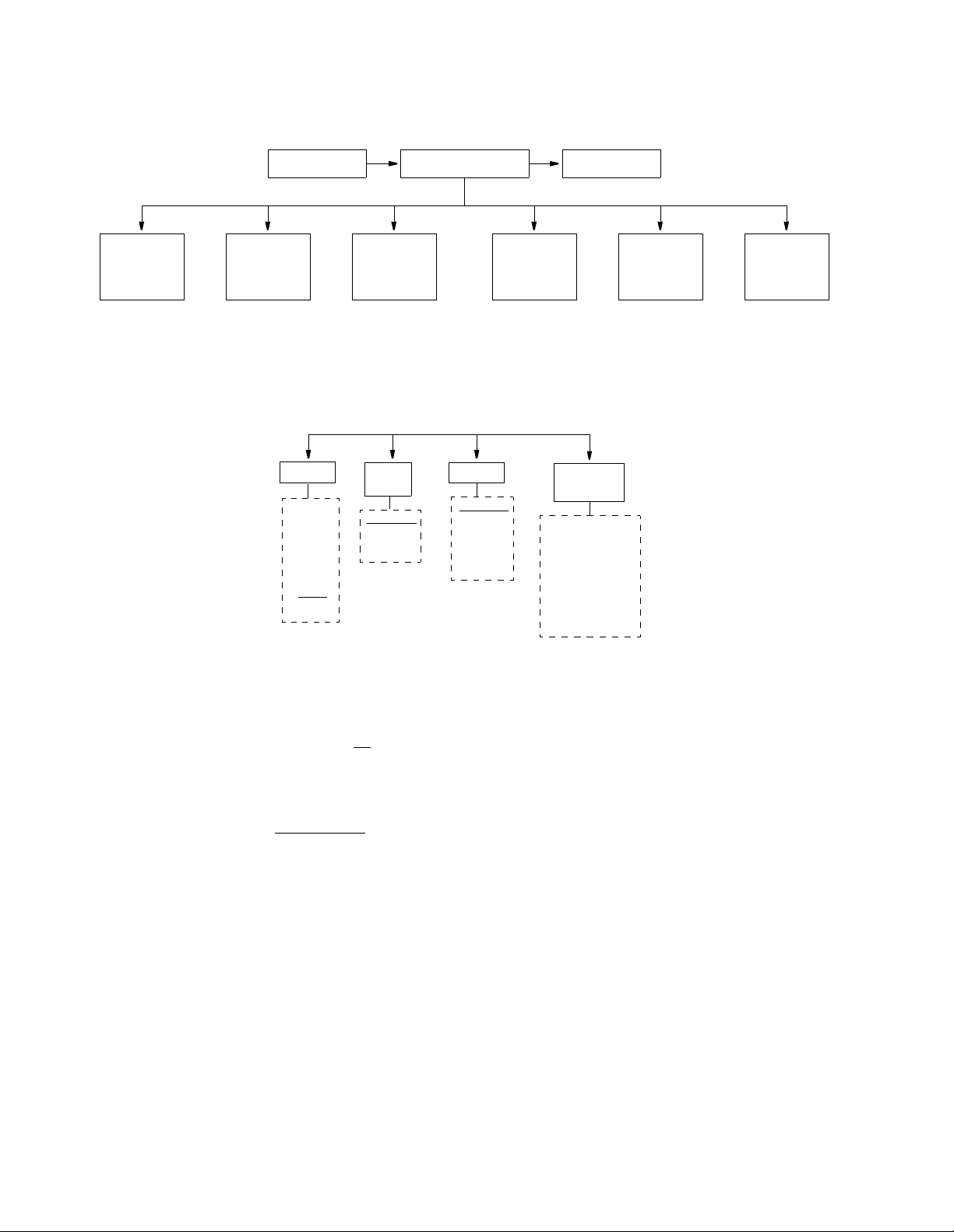
Main Menu
NET
Configuration
(page 14)
Configuration
Configuration
Network
The Main Menu is the first level of access for all th e functional m enus available.
Figure 3-8 displays the front panel menu structure.
Log OffLog On
Utilities
(page 23)
Displays
(page 26)
DTE
(page 16)
Figure 3-8
Main Menu
SNMP
Configuration
(page 18)
Front Panel Menu Structure
Diagnostics
(page 20)
The Network Configuration screen allows you to set the DDS mode, timing, and
alarm thresholds. Table 3-1 displays the Network Configuration menu structure.
Rate
2.4 K
4.8 K
9.6 K
19.2 K
38.4 K
56 K
64 K
Data
Mode
Standard
TxPORT
Timing
Network
Internal
DTE
Alarm
Thresholds
OOS LOS
OOF ART
Choices are --
1 to 30 sec.
(10 to 900 sec.
for ART)
Status
Figure 3-9
Network Configuration Menu Structure
Rate
Selects the network interfac e line rate. The available line rate s are 2.4, 4.8, 9. 6,
19.2, 38.4, 56
, and 64 kbps.
Data Mode
The unit can operate in two general modes. The DDS standard mode
STANDARD
provides complete compliance with industry DDS-I standards,
allowing the units to be end - to -end compatible and interoperate with other
vendors DDS compli ant DSUs. For a wider variety of applications, the unit can
operate in the TxPORT proprietary mode. In this mode, TxPORT equipment must
be located on both ends.
The DDS stan dard operati ng mode match es the DTE rate to the line rate. I n this
mode, the DTE interface operates synchronously at the selected line rate. These
selections are shown as STD in Table 3-1.
The TxPORT proprietary mode is used to support asynchronous DTE data, rate
adaptation of subrate DTE data onto 56 or 64 kbps lines, and provide an
end-to-end communications channel between DDS units. The specific DTE
data/loop rate combinations are shown as TXP in Table 3-1.
Page 27

Main Menu 15
Ta b l e 3 - 1
DTE
Rate
2.4K sync
2.4K async
2.4K sync
2.4K async
4.8K sync
4.8K async
4.8K sync
4.8K async
9.6K sync
9.6K async
9.6K sync
9.6K async
19.2K sync
19.2K async
19.2K sync
19.2K async
Data Rates
Comm
Channel
yes
yes
yes
yes
yes
yes
yes
yes
2.4
kbps
STD
TXP
4.8
kbps
STD
TXP
9.6
kbps
STD
TXP
19.2
kbps
STD
TXP
38.4
kbps
56
kbps
TXP
TXP
TXP
TXP
TXP
TXP
TXP
TXP
TXP
TXP
TXP
TXP
TXP
TXP
TXP
TXP
64
kbps
TXP
TXP
TXP
TXP
TXP
TXP
TXP
TXP
TXP
TXP
TXP
TXP
TXP
TXP
TXP
TXP
38.4K sync
38.4K async
38.4K sync
38.4K async
yes
yes
STD
TXP
TXP
TXP
TXP
TXP
TXP
TXP
TXP
TXP
54K sync yes TXP
56K sync
56K sync yes
57.6K async
57.6K async yes
STD TXP
TXP
TXP TXP
TXP
62K sync yes TXP
64K sync STD
TXP - The unit is operating in the TxPORT proprietary mode. TxPOR T equipment must be located on
both ends.
STD - The unit is operating in an industry standard mode. It will interoperate with other vendor
equipment.
Comm Channel - A n embedded c ommunicatio ns channel is provided acros s the networ k. This feature is
only available i n TxPORT pro prietary mo de.
Page 28

16 C
HAPTER
3: F
RONT PANEL INTERFACE
Timing
The PRISM 4101 can source its timing from three choices. With NETWORK
selected, timing is derived from the network recovered clock (the normal DDS
mode). With DTE selected, the unit synchronizes to the clock recovered from the
DTE port (DTE clocking is supported only in Standard mode). With INTERNAL
selected, the internal oscillator’s frequency standard is used for all timing.
Alarm Thresholds
The unit can be pr ogrammed to generate an alarm condition based on a specific
level of performance degradation. Alarm thresholds are set for periods of 1, 2, 3, 4,
5, 10, 20, and 30 consecutive seconds for the OOS, OOF, and LOS parameters. A
field set to [--- ] causes t he unit not t o alarm o n that stat istic. To effectively disable
alarm reporting, set all fields to [-- -].
OOS - Sets th e Out of Ser vice second s thresho ld. This oc curs when the OOS co de
is received from the DDS network. The default value is disabled [---].
LOS - Sets the loss of signal seconds threshold. The default value is 5
.
OOF - Sets the Out of Frame seconds threshold. This occurs on receipt of OOF
code from the DDS network. The default value is disabled [- - -].
ART - Sets the alarm reset timer. The setting determines when the Alarm
Indication/Contacts are cleared after the last error. The choices are 0, 10, 20, 30
,
60, 90, 100, 200, 300, 400, 500, 600, 700, 800, and 900 seconds.
DTE Configuration The DTE Configuration menu sets the operating parameters for the data port (V.35
or RS-232). Figure 3-10 displays the menu structure.
Mode
Sync
Async
2.4K 4.8K
9.6K 19.2K
38.4K
54K 56K
57.6K
62K 64K
InterfaceRate
RS-232
V.35
Anti-
Stream
Timer
Off
10 sec
30 sec
60 sec
Figure 3-10
DSR
Force On
Test>
Off
DTE Configuration Menu Structure
DCD
Force On
Idle>
Off
RTS
Force On
Normal
Circuit
Assur.
Off
On
RTS/
CTS
Normal
Long
V.5 4
Loop
Enable
Disable
DTR
Alarm
Enable
Disable
Mode
The unit can operate in two general modes (sync and async). When a unit is
configured for asynchronous DTE data, it operates in the TxPORT proprietary
mode and requires another PRISM 4101 on the remote end. The supported
asynchronous DTE rates are listed in Table 3-1. The following parameters must be
set for asynchronous operation; the number of async bits per character is 8, the
number of stop bits is 2, and parity is none.
Page 29

Main Menu 17
Rate
Selects the DTE interface line rate. The choices are 2.4, 4.8, 9.6, 19.2, 38.4, 54,
56, 57.6, 62, or 64 kbps. The available rates depend on the mode and the DTE
format. The default is 56 kbps in STD mode
.
Interface
This display-only field sh ows which ele ctric al interfa ce is ac tive (either the V.35 o r
the RS-232).
Antistreaming Timer
This timer is used to prevent a streaming DTE, on a tributary DSU in a multi-point
circuit, from locking up the circuit. If the RTS lead from the DTE stays constantly
active for the anti-streaming time, the unit shuts off data transmission into the
network. When ever RTS go es inactive, the anti-s treaming tim er is reset. Th e timer
can be turned Off
or set for 10, 30, or 60 seconds.
DSR
Data Set Ready is output from the unit to the DTE. Its behavior can be set to
Test>Off where DSR is On except when the unit is in test or set to Forced
On all
the time regardless of any unit condition.
DCD
Data Carrier Detect is output from the unit to the DTE. Its behavior can be set to
Idle>Off where DCD is On except when the unit is receiving idle code, OOS code,
OOF code, or LOS from the network or Forced
On al l the time regardle ss of any
unit condition.
RTS
Request To Send is an input to the unit from the DTE. Clear To Send is an output
from the unit to the DTE. The behavior of RTS and CTS is set as follows. In the
Normal setting, the unit reacts to RTS from the DTE. When RTS is On, the unit
transmits data norm ally and turns CTS On (depending on the setting of Circui t
Assurance an d after the dela y set by the RTS/CTS Delay option). When RTS is
Off, the unit transm its idle code to the network and tu rns CTS Off. In the Forc ed
On setting, the unit ignores the state of the RTS lead from the DTE and forces it
On internally and forces CTS O n.
Circuit Assurance
This option allows the CTS control lead to respond to the data signal from the
network. With Enabled se lected, the unit will turn Off the CTS le ad when
receiving idle code (for example, if DCD is Off). With Disabled
selected, the state
of the CTS control lead is not affected by data signal from the network.
RTS/CTS Delay
This selection allows the user to choose the amount of delay on RTS to CTS
transition. When RTS Control is set to Normal, CTS will follow the state of RTS
Page 30

18 C
HAPTER
3: F
RONT PANEL INTERFACE
after some delay depending on the data rate and the setting of this field. This delay
can be Norm al
or Long with the times shown as foll ows.
Ta b l e 3 - 2
RTS/CTS Delay Options
DDS Rate Normal Option Long Option
2.4 kbps 8 ± 0.4 ms 16 ± 0.8 ms
4.8 kbps 4 ± 0.2 ms 8 ± 0.4 ms
9.6 kbps 2 ± 0.1 ms 4 ± 0.2 ms
19.2 kbps 1 ± 0.05 ms 2 ± 0.1 ms
38.4 kbps 0.5 ± 0. 025 ms 1 ± 0.05 ms
56 kbps 0.4 ± 0.02 ms 0.8 ± 0.04 ms
64 kbps 0.3 ± 0.015 m s 0.6 ± 0.03 ms
V.54 Loop
Selecting Enable
allows the unit to respond to inband V.54 loop commands. If
Disable is selected, the unit ignores these commands.
DTR Alarm
Selecting Enable allows the unit to alarm on loss of DTR. This occurs when the
DTE port sees that the DTR signal is low. The default setting is Disable
.
SNMP Configuration The SNMP (Simple Network Management Protocol) interface is a feature of the
unit which provides seamless integration and control of CSU / DSU functions
within an existing SNMP managed LAN/ WAN environment. SNMP management
stations are able to collect and analyze data from all network devices which
comply with the SNMP protocol and to manage those devices.
SNMP provides a standard means to moni tor the status of all compatible network
elements. The PRISM 4101 management capabilities are expanded by the
inclusion of the TxPORT MIB and the enterprise DDS MIB. Objects in these
MIBs, and MIB loading instructions are listed in Appendix A.
The SNMP Configuration screens are used to configure the Ethernet, SLIP, or
Token Ring SNMP interfaces. It allows for the entry of those parameters required
for proper operation of the unit with an Ethernet, SLIP, or Token Ring based LAN
manager.
Unit
IP
Addres
Addresses are entered as follows: An underline appears
under the digit to be changed. SCROLL increments the
digits from 0 to 9. SELEC T accepts the current digit
and moves the cursor right. Press EXIT on t he last dig it
to enter the address and return the previous screen.
Router
IP
Addres
Subnet
Mask
Filter IP
Address
1-8
Trap IP
Address
Figure 3-11
Write
Comm.
1-6
Sets Read
Comm.
Enable
Disable
Text is entered as follows: An underline appears under the
character to be ch ange d. SCROLL cycles th rough th e char acter set. SELECT sets the character and moves the cursor
right. Pressing EXIT on the last character enters the name
and returns the previous screen. 58 characters are allowed.
SNMP Configuration Menu Structure
System
Contact
System
Name
System
Location
Reset
LAN
No
Yes
Page 31

Main Menu 19
The SNMP menu consists of alpha -numeric entry only (no selectable parameters).
The following three menu items use the format shown in the IP Address screen.
Each number has a range from 0 to 255 and is separated by a period.
132.016.232.000
>
Figure 3-12
Example IP Address
Unit I P Address
Accepts IP addresses. Each device connected to the LAN is required to have a
unique IP address identifier.
Router IP Address
Accepts the IP address of a default router, if one is present.
Subnet Mask
Provided to manually override the subnet mask setting which is otherwise
discover ed by the SNMP agent.
Filter IP Address
Accept the IP address of the source packet filter. If any of these fields are set,
access is allowed only by the specified IP addresses.
Trap IP Address
Accepts the IP address of a network device where alarm reporting traps are to be
sent. The unit detects and reports alarms and provides several options for reporting
them, one of which is SNMP traps. When a network alarm occurs, the unit sends a
trap message to up to six destinat ions on the user’s network.
Sets
Enables or disables the SET commands. If this field is set to No, the SN MP
manager wil be unable to change the unit’s configuration. Refer to Appendix A for
detailed information on these responses.
The following five menu items u se the format sh own in the System Edit screen.
The top line in each screen accepts a string of up to 58 characters which identifies
the appropriate group, person, device function, or unit location.
Read Community
>public
Figure 3-13
System Edit
Read Community
Accepts a character string identifying the group authorized to perform read
operations. The default setting is public
.
Page 32

20 C
HAPTER
3: F
RONT PANEL INTERFACE
Write Community
Accepts a character string identifying the group authorized to perform write
operations. The default setting is ‘ ’, which is a null string.
System Contact
Accepts a character string identifying the person responsible for a network device.
The default setting is no syst em contact
System Name
Accepts a character string identifying the functionality of the network device. The
default setting is no system name
System Location
Accepts a character string identifying the physical location of network device. The
default setting is no system location
Reset LAN
Allows you to reset the LAN interface of the unit. Selecting yes
reset to take place.
.
.
.
will cause the
This action will disrupt the data ser vice.
Diagnostics The Diagnostics screen allows test and maintenance functions to be performed on
the network, the DTE port, and the high speed ports. The unit recognizes inband
loopback requests. The unit also recognizes local testing and remote network
management loopback test configurations. The unit supports many ways to test the
service to and from the unit.
The PRISM 4101 has an internal 511 pattern generator and com parator. You can
select to tran smit the patte rn toward the DDS lin e/network or toward th e data
port/DTE i nterface. With the exception o f the si ngle patte rn, the B ERT test works
in the same man ner as in PRISM T1 products.
Loop
Mode
Uni
Bi
Local
Loop
Off
On
V.5 4
Loop
Off
On
Remote
Loop
Off
On
BERT
Function
Figure 3-14
BERT
Off
NET
DTE
Sync
(display)
In Sync
No Test
(display)
HH:MM:SS
Diagnostics Menu Structure
Time
Bit
Error
(display)
123456
Errored
Seconds
(display)
123456
Sync
Loss
(display)
123456
Reset
Yes
No
Page 33

Main Menu 21
Loop Mode
Allows you to choose how the data will be looped back. The choices are
Bidirectional
or Unidirectional.
When set to Uni directional, th e NET receive data is loop ed back to the NE T as
NET transmit data and continues to pass through the data port to the DTE as
shown in Figure 3-15. Transmit data from the DTE is terminated.
Line Loop
Figure 3-15
DTE
Unidirectional Loop
NET
When set to Bidirectional, the NET receive data is looped back to the NET as NET
transmit data as shown in Figure 3-16. Transmit data from the DTE is looped back
through the data port as receive data to the DTE.
Local Loop
Figure 3-16
During dial backup, the loop mode field is ignored and all loops are unidirectional.
✍
this allows testing of the DDS interface during dial backup without disrupting the
DTE/DBU data path.
DTE
Bidirectional Loop
NET
Local Loop
The choices are On and Off
. This loop occurs at the DDS network interface as a
bidirectional loop. It returns the DDS receive data to the DDS transmit line and the
PRISM 4101 transmit data to the unit receive data output.
Local Loop
In TxPORT mode, local loop functions differently. It is always a unidirectional loop,
implemented at the DTE interface. This allows the end-to-end data link to remain
operational during the loop.
Local Loop
(TxPORT Mode)
DTE
DTE
Data & Rcv FDL
Data & Xmt FDL
NET
NET
V.54 Loop
The choice s are On and Off
. This loop occurs at the DTE data port interface and is
activated upon receipt of inband V.54 loop codes for at least two seconds followed
by all ones in the network receive data stream. This loop is unidirectional and
retransmits the PRISM 4101 received data on the unit transmit data including the
remapped loop code. Receive data is unaffected (but includes the modified loop
codes) and circuits DSR and DCD are Off. You may instruct the unit to transmit
inband V.54 loop code to the remote end unit causing it to enter a V.54 loop.
Page 34

22 C
HAPTER
3: F
RONT PANEL INTERFACE
Remote Loop
The PRISM 4101 can not transmit alternating DSU loop code or cause sealing current
reversal to activate a loop on the remote end unit.
The choices are On and Off
. This loop instructs the unit to transmit inband V.54
loop code to the remote end causing the remote unit to enter a V.54 loop. Refer to
the section entitled V.54 Loop on page 18 for specific information concerning the
V.54 loop.
BERT Function
The following menus offer selections for starting a BERT (Bit Error Rate Test)
along with test results.
BERT. This selection turns the BERT to Off or On towards the Network (NET) or
towards the DTE.
Sync. Displays the cu rrent state of pattern sync d uring a test. If n o test is in
progress, then No Test is displayed.
Time. Displays the elapsed time since a timed test began. A value is displayed
only when a test is running (in the HH:MM:SS format).
Bit Errors. Displays the total number of bit errors detected since the test began or
since error st atistics were last cleared.
Errored Seconds. Displays the number of errored seconds that have been detected
since the tes t began or since erro r statistics were last clea red.
Sync Loss. Displays the number of times during the test period that the BERT
pattern detector lost sync.
Reset. When set to Yes, the BERT error counts an d elapsed ti me values are
cleared to zero . This parame ter then return s to No automati cally.
Page 35

Main Menu 23
Utilities The Utilities m enu allows you to perform the various functions. Figure 3-17
diagrams the Utilities menu structure.
Save
Config
No
Yes
Contrast
Cmd.
Disable
Enable
Daily
Activate
1 - 15
Daily
Periods
Time
HH:MM:SS
DBU
Activator
OOF
LOS
OOS
ANY
Date
MM:DD:YY
Format
Sync
Async
IP
Port
SLIP
ENET*
TOKEN*
*(w/ LAN
NIC only)
DBU
Rate
2.4, 4.8,
9.6, 19.2
38.4, and
57.6 K
TOKEN
,
Rate
16 M
4 M
DBU
Mode
Originate
Answer
CORIG
CANSW
SLIP
1.2 K
2.4 K
9.6 K
19.2 K
DBU
Password
Dial
Back
Up
DBU
Phone #
Use same
method as
SNMP
‘Edit’ field
SUPV
1.2 K
2.4 K
9.6 K
19.2 K
DBU
Init
String
Use same
method as
SNMP
‘Edit’ field
Set
Password
DBU
HGUP
String
Use same
method as
SNMP
‘Edit’ field
Sun Start [0 - 24]
Sun Stop [0 - 24]
Mon Start [0 - 24]
Mon Stop [0 - 24]
Tue Start [0 - 24]
Tue Stop [0 - 24]
Wed Start [0 - 24]
Figure 3-17
Wed Stop [0 - 24]
Thu Start [0 - 24]
Thu Stop [0 - 24]
Fri Start [0 - 24]
Fri Stop [0 - 24]
Sat Start [0 - 24]
Sat Stop [0 - 24]
Utilities Menu Structure
Use same
method as
SNMP
‘Edit’ field
Save Configuration
Selecting Yes saves the current configuration to memory and restarts the unit.
This actio n will br iefly di srupt the DDS ser vice.
Contrast
Sets the LCD display contrast to a value between 0 and 15. When sc rolling
through the values, at some point the screen will appear blank. If this occurs, keep
scrolling until the contrast is best for viewing.
Page 36

24 C
HAPTER
3: F
RONT PANEL INTERFACE
Time
The current ti me is set by ente ring each digit in the standard 2 4-hour HH:MM :SS
format. Each field is range checked and automatically limited to the appropriate
range of values.
Date
The current da te is set by ente ring each digit in the standard MM/ DD/YY date
format. Each field is range checked and automatically limited to the appropriate
range of values.
IP Port
The choices for the IP port are SLIP
, TOKN, and ENET. These options can only
be selected if the unit is optioned with the corresponding LAN NIC.
TOKEN Rate. Appears only if th e IP Port is set to TOKEN. The choices for the
token ring rate are 4 and 16 Mbps.
SLIP Rate. This optio n appears onl y when the IP Por t is set to SLIP. T he choices
for the SLIP line rate are 1.2, 2.4, 9.6, and 19.2
kbps.
Dial Back Up
The unit offers two methods of providing an alternate data path in cases where the
DDS network connection fails. These are an internal 33.6 modem or an external
device, synchronous or asynchronous, which is compatible with a switched circuit
technology. The 10-pin modular DBU port provides the access for either method.
Command. The choices are ENABLE, DIS ABLE, DAILY, and ACTIVATE.
DISABLE - Does not allow the unit to respond to a dial backup situation.
ENABLE - Allow the unit to respond to a dial backup situation.
DAILY - Allows the unit to respond to a dial backup situation only during the
specified time period fo r that d ay. Selecting this opt ion causes the Dail y Periods
configuration field to be activated at the end of the Scroll menu. See Daily Periods
on page 25 for configuration information.
ACTIVATE - Forces the unit to place a call and switch to the dial backup device.
DBU Activator. Used to select the crit eria that the u nit will use to ac tivate the dial
backup sequ ence. The cho ices for the D ial Backup U nit Activator are LOS
, OOS,
OOF, and ANY Alarm Thresholds.
Format. Sync or Async, depending on DBU device capabilities. DBU device
configuration and dialing is always Async.
DBU Rate. Used to select a dial backup rate of 2.4, 4.8, 9.6, 19.2, 38.4, or 57.6
kbps. The applicable rates depend on the type of modem used or whether a
terminal adapter is used. If DBU format is Sync, this field only applies during the
configuration and dialout process.
DBU Mode. Used to select the call response mode that the unit will use.
Page 37

Main Menu 25
✍
ORIGINATE - the unit will initia te a call when ne eded.
ANSWER - the unit will only answer an incoming call.
CORIG - (Call Back Originate) the unit calls another modem, delivers a password,
and then wait s for the other m odem to call ba ck.
CANSW - (Call Back Answer) the unit answers a call but checks for a password
before diconnecting and calling the other device back.
DBU Password. If DBU Mode is set to Callback Originate or Callback Answer,
this prompt appears after the DBU Mode field, otherw ise it will be hidden. A two
to nine character representing the ‘trigger’ character, and the remaining characters
representing the actual password. For example, the ‘trigger’ character might be a
“:” and the intended password might be “4101”. Enter “:4101” in the password
field. This field requires a string input. Each number is entered using the Scroll
key until the desired character is displayed. The Select key moves the cursor to the
next position. Continue this pattern until the last character has been selected and
press Exit.
Password strings are case sensitive and must be the same in both the Callback
Originate and Callback Answer units. Consul t the external DBU device manual for
further commands.
DBU Phone #. Used to enter the telephone number that the unit will call. This is a
don't care field when the DBU Mode is set to ANSWER. This string must include
the ATDT or ot her approp riate comman d prefix.
DBU Init String. Used to send an initialization string to an external device.
DBU Disconnect String. Sent to an external device upon completion of the data
transfer so th at the device will di sconnect fro m the remote end .
Daily Periods. Allows you to select the time (zero to 24 hours) of a given day the
dial backup option will place a backup call. You must enter a starting hour and an
ending hour for the specified day. A setting of [8] - [17] means the unit will allow
dial backup operations from 8:00 a.m. to 5:00 p.m. on the specified day. A setting
of [0] - [24] m eans that the unit will call out any time there is an alarm condition
on the network.
SUPV Rate
The choices for the supervisory line rate are 1.2, 2.4, 9.6, and 19.2
kbps.
Edit Password
The unit is factory shipped with the password disabled
(factory default). A
password is se lected by en tering up to ten alpha numeric char acters. E ach charac ter
is entered by scrolling until the desired character is displayed, then pressing Select.
Continue this pattern until the last character is selected and then press Exit. The
password function is disabled by entering this field and pressing Exit without
selecting any characters.
The password is case sensitive and must be entered exactly as programmed.
Pressing Select on the Dial Backup field brings up the following submenus.
Page 38

26 C
✍
HAPTER
RONT PANEL INTERFACE
3: F
Status Displays Selecting Status from the Main Menu brings up two different displays as shown in
Figure 3-18. You can switch between these two displays at any time by pressing
the Scroll button.
The Select key is not valid. Use the Scroll key only.
Status
LOS
OOS
DBF
DBA
Test
Figure 3-18
RTS CTS CD TR SR
*
Asterisk indicates
active signal
Status Displ ay Menu Structure
The first display can be blank, or show different indicators.
LOS - The unit is not currently receiving a valid DDS signal.
OOS - The unit is currently receiving the Out of Service pattern over the DDS
interface.
OOF - The unit is currently receiving the Out of Frame pattern over the DDS
interface.
DBA - This message is sent when the dial backup becomes active notifying you
that the ma in data p ath is down.
DBF - This message is sent upon failure of the dial backup link to connect or upon
a loss of carrier. The unit continues to attem pt a DBU link.
TEST - The unit is running a BERT or is in a lopback mode.
The second display shows the status of various control leads on the RS-232 or
V.35 DTE port. An asterisk (*) below a given signal name indicates the control
lead is active (asserted ).
Page 39

4
✍
T
ERMINAL
The software interface is embedded inside the PRISM 4101 and requires an ANSI
compatible VT100 terminal (ASCII), or a computer running an ANSI terminal
emulation program (PROCOMM PLUS
through the LAN or SLIP ports using a telnet session at bit rates from 1.2 to 19.2
kbps. Only one telnet session may be active at any given time.
I
NTERFACE
). You can also access this interface
Interface Access
Once a compatible V T100 terminal is properly connected to the unit, you can start
a terminal interface session by sending a BREAK command to the unit or by
pressing the Return or Enter key four times.
If you are using a modem and you send a key sequence before receiving the Connect
message, the modem will hang up due to the any about key feature of the modem.
If a password has been previously established, you must enter the correct password
to continue the session. The password is case - sensitive. If you have forgotten your
password, note the date and time shown on your screen and contact TxPORT
Technical Support. You can establish or modify your password through the
Utilities screen on page 50. Once a valid password has been entered, the Main
Menu screen is displayed.
If you do not enter a keystroke for 10 minutes, the terminal interface logs off
automatically.
Page 40

28 C
HAPTER
4: T
ERMINAL INTERFACE
Interface Conventions
Device Type
and Revision
Menu Title
Messages
All terminal interface screens have several common components as displayed in
Figure 4-1.
Element ID
Date / Time
Terminal Interface Layout
Device Type and
Revision
Figure 4-1
The device type (such as PRISM 4101) and the revision control numbers are
shown in the upper left corner. The first number is the hardware revision and the
second number is the software revision. Information is displayed for the near end
unit (connec ted directly to the terminal) o n the top line, and for the far end u nit
(connected to the network interface) on the second line. Far end information is
displayed only when available, otherwise, the screen displays a no remote access
message. Refer to this information when contacting the factory with inquiries.
When connected to a PRISM 3030 or a PRISM 3060, the second line displays the
✍
physical slot number and DSU number (Slot # DSU #) of the DSU inside the PRISM
3030 or PRISM 3060 unit.
Date/Time The to p right corner of the termin al scree n display s the curr ent date a nd time. The
setting of th ese functions is described in the section e ntitled Utilit ies on page 50.
Element ID Below the header (PRISM 4101), the Element ID is displayed. Refer to the section
entitled Management Ports on page 45 for information on the Element ID.
Menu Title The menu title (t hird line, center) denotes the general classification of functions
currently accessible such as Main, Management Ports, or Performance.
Messages Diagnostic messages may be displayed at the bottom of the screen.
Page 41

Cursor 29
Cursor
The terminal interface uses a h ighlighted cursor to make se lections fr om menus
and select fields within screens. The cursor is moved in different ways, depending
on the terminal emulation program used. Most programs use the Tab and Shift+Tab
keys. Other programs use the arrow keys. For keyboards which do not have these
standard keys or have only some of them, an alternate set of cursor control
commands is provided. Each command is performed by pressing a lett er key while
holding down the Control key. Alternate commands may be freely mixed with the
keyboard commands at your discretion.
Ta b l e 4 - 1
Keyboard Command Alternate Command
Left arrow Control+S
Right arrow Control+D
Up arrow Control+E
Down arrow Control+X
Backspace Control+H
Delete Control+Z
Refresh screen Control+U
Key board / Alternate Commands
Control+T While in a remote screen, toggles
from remote to local screen.
Field Types
Each screen is made up of fields. The two basic field types are user-selectable and
display-only. Fields without brackets or parenthesis are display-only. They cannot
be changed on the screen.
If the highlighted cursor can be moved to a field, it is a user selectable field. User
selectable fields allow for changes to be made or commands to be executed. Most
user selectable fields are enclosed in brackets or parentheses.
Fields enclosed in brackets [ ] offer you a list of selections from which to choose.
The selections may be toggled by pressing the Spacebar. Each time it is pressed, a
new item appears. When the appropriate choice is displayed, press Return to select
it.
There are two methods for manipulating fields enclosed in parentheses ( ).
Pressing the Return key on a field such as Reset and Start Test immediately
executes the function. Typing input when the field is highlighted, such as the
Subnet Mask field causes the curr ent entry to be rep laced with the new characters.
To edit an existing entry rather than replace it, you need only move the cursor to
the point that needs editing. Characters may then be inserted or deleted. Typed data
is always in serted rath er than typed over. If the field is full, th ough, at least one
character must be deleted to add another. Many fields of this type may also be
toggled by pressing the Spacebar. Other fields are range checked, where you are
not allowed to exit with an illegal value set.
Main Menu
The Main Menu screen displays the available menu options. To activate any menu,
highlight the desired selection and press Return. You may exit this menu and any
subsequent menu by pressing the Escape key. When you exit the Main Menu, the
Page 42
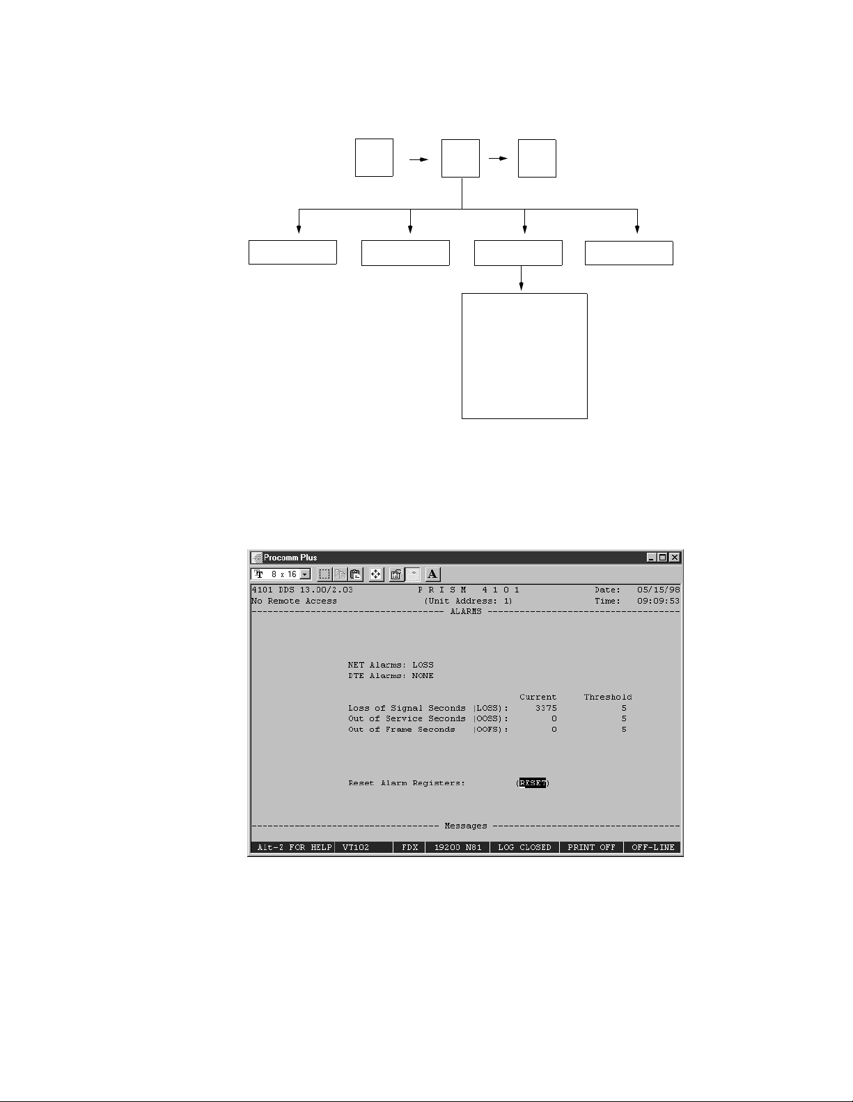
30 C
HAPTER
4: T
ERMINAL INTERFACE
terminal inte rface program terminates. This is a valid way to end a user session.
When any other me nu is exited, the previous screen is retu rned. The men u
structure (Figure 4-2) shows all the screens accessible from the Main Menu.
Main
Menu
DDS Network Parameters
DTE Port Parameters
Alarm Parameters
TCP/IP Parameters
SNMP Parameters
Management Ports
Dial Backup Parameters
Summary
Log
Off
Utilities
Alarms
Figure 4-2
Log
On
Maintenance Configuration
PRISM 4101 Menu Structure
Alarms The Alarms screen (Figure 4-3) allows you to view the current alarm status of the
network and the DTE interfaces. The parameters shown on the Alarms screen are
updated at approximately five second intervals.
Figure 4-3
Alarms Screen
Page 43

Main Menu 31
NET Alarms
This status line displays the current network signal alarm state (Table 4-2) as
determined by the selectab le threshol ds set in the Alar m Configuration screen on
page 41.
Ta b l e 4 - 2
Alarm Description
OK No alarm threshold has been exceeded, although errors may exist which do not
LOSS The Loss Of Signal Seconds threshold is exceeded.
OOSS
OOFS The Out Of Frame Seconds threshold is exceeded.
DBA Dial Backup is Active.
DBF Dial Backup failed.
DTR The DTE port sees the DTR signal as low.
NET/DTE Alarm Indicators
exceed thresholds.
The Out Of Service Seconds threshold is exceeded.
No status is Available
DTE Alarms
This status li ne displays t he selected ele ment’s current DTE sig nal alarm stat e
(Table 4-2). DTE alarms are enabled or disabled through the DTE Port Parameters
screen on page 37.
Loss of Signal Seconds
The LOSS alarm displays, in the Current column, the number of consecutive
seconds the unit received signal has been interrupted. The Threshold column
displays the maximum value (in seconds) that must be met or exceeded to generate
an alarm. If the Threshold value is set to zero, the alarm mechanism is disabled.
Refer to the section entitled Alarm Configuration on page 41 to set the alarm
parameters.
Out of Service Seconds
The OOSS alarm displays, in the Current column, the number of consecutive
seconds the unit has received the out of service code. The Threshold column
displays the maximum value (in seconds) that must be met or exceeded to generate
an alarm. If the Threshold value is set to zero, the alarm mechanism is disabled.
Refer to the section entitled Alarm Configuration on page 41 to set the alarm
parameters.
Out of Frame Seconds
The OOFS alarm displays, in the Current column, the number of consecutive
seconds the unit received the out of frame code. The Threshold column displays
the maximum value (in seconds) that must be met or exceeded to generate an
alarm. If th e Thre shol d value is s et to z ero, the ala rm me chanis m is d isabl ed. R efer
to the section entitled Alarm Configuration on page 41 to set the alarm parameters.
Reset Alarm Registers
Pressing the Return key with the Reset option highlighted zeros the value of all
Current ala rm param eters.
Page 44

32 C
4: T
HAPTER
ERMINAL INTERFACE
Maintenance When in-depth testing is necessary, you can use the Maintenance screen
(Figure 4-4) to perform loop tests and/or BERT functions on the DDS circui t.
BERT is performed by using on-board test facilities. Additional test equipment is
not required. Some of these tests may also be activated by the front panel buttons
as described in the section entitled Diagnostics on page 20.
Figure 4-4
Maintenance Screen
Clear Tests
Pressing Ret urn clears al l tests and any line loops that have been init iated.
Clear Alarms
Pressing Return clears all near end alarms. If alarm conditions remain present,
alarms are re activated once thresho lds are exceed ed.
Loop
The type of loop is chosen by toggling the Spacebar and is executed by pressing
Return. Options are LOCAL
, V.54, and FAR V.54.
Unloop
Pressing Ret urn takes down the sp ecified loop from the currently s elected por t.
The type of loop is chosen by toggling the Spacebar and is executed by pressing
Return. Options are LOCAL
, V.54, and FAR V.54.
Loop Mode
Allows you to choose how the data will be looped back. The choices are
BIDIRECTIONAL
or UNIDIRECTIONAL.
Page 45

Main Menu 33
When set to Uni directional, th e NET receive data is loop ed back to the NE T as
NET transmit data and continues to pass through the data port to the DTE as
shown in Figure 4-5. Transmit data from the DTE is terminated.
Line Loop
Figure 4-5
DTE
Unidirectional Loop
NET
When set to Bidirectional, the NET receive data is looped back to the NET as NET
transmit data as shown in Figure 4-6. Transmit data from the DTE is looped back
through the data port as receive data to the DTE.
Local Loop
Figure 4-6
During dial backup, the loop mode field is ignored and all loops are unidirectional.
✍
This allows testing of the DDS interface during dial backup without disr upting the
DTE/DBU data path.
DTE
Bidirectional Loop
NET
There are four loop types that can be activated from the PRISM 4101. They are
line loop, data loop, V.54 loop, and local loop.
Line Loop. Occurs at the D DS network interface and is activated by the reversal of
the simplex, 20 mA sealing current. This is a unidirectional loop that ignores the
unit transmi t data and retr ansmits the re ceived DDS data. Rece ive data is
unaffected and circuits DSR and CD are optionally forced Off.
Line Lo op
Data Loop. Occurs at the data port (DTE) interface and is activated when the unit
DTE
NET
receives alternating loop codes in the network receive data stream. Technically, it is
activated by the receipt of at least four consecutive loop commands and remains
looped as long as each third pattern byte is the loop command. It returns to normal
operation after at least four pattern bytes that are not the loop command. This is a
unidirectional loop that retransmits the PRISM 4101 received data on the unit
transmit data including the remapped loop code. Receive data is unaffected (but
includes the modified loop codes) and circuits DSR and CD are Off.
Data Loop
V.54 Loop
V.54 Loop. Occurs at the DTE data port interface and is activated upon receipt of
DTE
NET
inband V.54 loop codes for at least two seconds followed by all ones in the
network receive data stream. This loop is unidirectional and retransmits the PRISM
4101 received data on the unit transmit data including the remapped loop code.
Receive data is unaffected (but includes the modified loop codes) and circuits DSR
Page 46
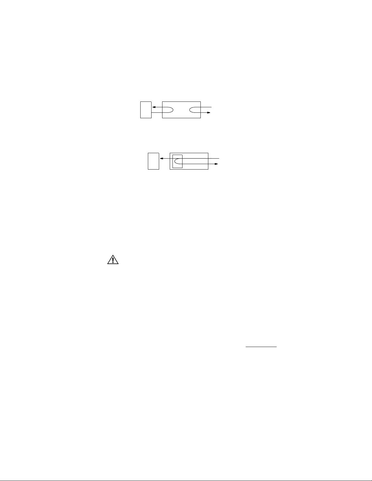
34 C
HAPTER
4: T
ERMINAL INTERFACE
and DCD are Off. You may instruct the unit to transmit inband V.54 loop code to
the remote end unit causing it to enter a V.54 loop.
The PRISM 4101 can not transmit alternating DSU loop code or cause sealing current
reversal to activate a loop on the remote end unit.
Local Loop.
This loop occurs at the DDS network interface as a bidirectional loop.
It returns the DDS receive data to the DDS transmit line and the PRISM 4101
transmit data to the unit rece ive data output.
Local Loop
In TxPORT mode, local loop functions differently. It is always a unidirectional loop,
implemented at the DTE interface. This allows the end-to-end data link to remain
operational during the loop.
Local Loop
(TxPORT Mode)
DTE
DTE
Data & Rcv FDL
Data & Xmt FDL
NET
NET
Enable Far End Datalink
The Far End Datalink allows you to establish end-to-end communications as a
diagnostic tool. When in the normal mode of operation, you can establish
end-to-end communications by changing the Data Mode on the near end and then
pressing Return on the Enable Far End Datalink field. This function changes the
Data Mode on the far end unit to TxPORT mode also. You can then perform
functions at that end of the circuit. Normal operation can be resumed by changing
the Data Mode back to standard on the far end unit first and then the near end.
This operation will disrupt the data path.
BERT
Specifies the direction the BERT signal will be sent. If the direction is changed
from the front panel, the new choice is updated on the terminal interface. The
choices are DDS NETWORK and DTE. The Start Test field must be used to
activate the BERT, as this field only specifies the direction.
Test Length
Defines the run- time of test pattern generation and error accumulation. The
choices are 15 min, 30 min, 60 min, 24 Hour, and Continuous
.
Pattern Sync
Displays the current state of pattern sync during a test. If no test is in progress,
NO TEST is disp layed. If a tes t is active, but the receiver is not in patte rn sync,
NO SYNC or SYNC LOST is displayed. If the receiver is in pattern sync, IN
SYNC or SYNC RECOV is displayed.
Elapsed Time
Displays the amount of time elapsed since a timed test began or, if completed, the
total test ti me.
Page 47

Main Menu 35
Bit Errors
Displays the total number of bit errors detected since the test began or since error
statistics were cleared (up to a maximum number of 999,999).
Errored Seconds
Displays the number of asynchronous errored seconds that have been detected
since the test began or since error statistics were last cleared. This parameter
includes bit error seconds and sync loss seconds.
% EFS
Displays the percentage of Errored Free Seconds. This number is derived from the
number of error free seconds divided by the number of seconds accumulated in the
Elapsed Time fiel d.
Start Test
Pressing Return with the cursor on this field starts the selected test pattern. Once
the test has started, TEST IN PROGRESS appears. To end the test, press Return
with STOP TEST highlighted.
Reset Errors
Pressing Ret urn with the cu rsor on this field ca uses the test err or results to be
cleared to zero. The test continues running.
NET / DTE Status
Displays the fault status of the network and the far end DTE. They indicate current
fault conditions. They do not indicate that alarm thresholds are exceeded. Table 4-3
displays the status indicators.
Ta b l e 4 - 3
Alarm Description
OK No alarm although errors may exist which do not exceed thresholds.
LOSS Loss Of Signal Seconds.
OOSS
OOFS Out Of Frame Seconds.
DBA Dial Backup is Active.
DBF Dial Backup failed.
DTR The DTE port sees the DTR signal as low.
NET/DTE Status Indicators
Out Of Service Seconds.
No status is Available
Near Loops
Displays the loop status of the near element.
Far Loops
Displays the loop status o f the far element.
Configuration The Configuration menu (Figure 4-7) allows you to view and set configuration
parameters for the network elements. To send a new configuration to the unit, you
Page 48

36 C
HAPTER
4: T
ERMINAL INTERFACE
must press Return on one of the fields or exit the screen. The underlined values are
the factory default par ameters.
Changing any of the line or DTE settings briefly interrupts end-to-end traffic as the
new setting is put into effect. Choosing an incorrect or invalid setting may disrupt
end-to-end traffic until a proper setting is established.
Configuration Menu
DDS Network
Parameters
(page 36)
SNMP
Parameters
(page 43)
Figure 4-7
Configuration Menus Structure
DTE Port
Parameters
(page 37)
Management
Ports
(page 45)
Alarm
Parameters
(page 41)
Dial Backup
Parameters
(page 46)
TCP/IP
Parameters
(page 42)
Summary
(page 49)
DDS Network Parameters
The DDS Network Parameters screen (Figure 4-8) allows you to review and set
line parameters for the selected element on the DDS circuit.
Figure 4-8
Rate. Selects th e network int erface line rate. The unit must be manuall y set to a
specific line rate. The rate choices are 2.4, 4.8, 9.6, 19.2, 38.4, 56
Data Mode. When set to TxPORT, the unit operates in the proprietary mode where
DDS Network Parameters Screen
and 64 kbps.
TxPORT specific equipment must be located on both ends. When set to
STANDARD
, the unit operates in an industry standard mode allowing it to
interoperate with equipment from another vendor.
Page 49

Main Menu 37
Timing. The unit can source its timing from three choices. NET uses the network
recovere d clock (the normal DDS mode). DTE uses the clock recovered from the
DTE port and is allowed only when the Data Mode is set to Standard. INT uses the
internal os cillator (25 ppm) for all tim ing.
Circuit Assurance. Allows the CTS control lead to respond to the data signal from
the networ k.
If On is selec ted, the un it will turn Off the CTS lead wh en receiving idl e code (for
example, if DCD is Off). If Off
is selected, the state of the CTS control lead is not
affected by data signal from the network.
When Circuit A ssurance is se t to Off, CTS follows RTS. When RTS transitions to
the On stat e, CTS will t ransi tion to the O n state after the RTS/CTS delay. CTS will
transition to the Off stat e within o ne bit tim e when RTS transiti ons to the Off state.
When Circuit A ssurance is se t to On, CTS follows RTS if DCD is On. Wh en RTS
transition s to the On state , CTS will trans ition to the On s tate after the RTS/CTS
delay if DCD is O n. CTS will tran sition to the Off state when RTS transitions to
the Off state. CTS is Off if DCD is Off.
RTS should be set to Normal on the DTE PORT parameters w hen Circuit
Assurance is On. The Force DCD option will be changed to N ormal.
Anti streaming Timer. The Antistreaming Timer is used to prevent a streaming DTE
on a tributary DSU, in a multi-poi nt circuit, fro m locking up the circuit. It is
controlled by RTS. If RTS remains enabled long enough for a timeout to occur, the
unit will drop CTS and stop sending DTE data. The Antistreaming Timer is reset
when RTS transitions to the Off state. Choices are Off
, 10, 30, and 60 seconds.
DTE Port Parameters
When operating in the proprietary mode, an end-to-end management link is
established between units. Remote communications between units operates on a
sideband channel and is not disruptive to the customer’s data traffic. On a 56K
loop, the maximum DTE rate is 54 K sync (57.6 K async) and on a 64K loop, the
maximum DTE rate is 62K. At line rates less than 56 kbps, only async format is
Page 50

38 C
HAPTER
4: T
ERMINAL INTERFACE
allowed. The DTE Port Parameters screen (Figure 4-9) sets the following operating
parameters for the V.35 or RS-232 ports.
Figure 4-9
Por t Ty pe . The active port is a display only field. The PRISM 4101 automatically
DTE Port Parameters Screen
switches to the connector supplying data.
Por t R a te. Selects the DTE interface line rate. The choices are 2.4, 4.8, 9.6, 19.2,
38.4, 54, 56
, 57.6, 62, or 64 kbps (Table 4-4). The available choices are based on
the Data Mode, DDS Rate, and DTE Port Format.
Page 51

Main Menu 39
Ta b l e 4 - 4
DTE
Rate
2.4K sync
2.4K async
2.4K sync
2.4K async
4.8K sync
4.8K async
4.8K sync
4.8K async
9.6K sync
9.6K async
9.6K sync
9.6K async
19.2K sync
19.2K async
19.2K sync
19.2K async
DTE Rates
Comm
Channel
yes
yes
yes
yes
yes
yes
yes
yes
2.4
kbps
STD
TXP
4.8
kbps
STD
TXP
9.6
kbps
STD
TXP
19.2
kbps
STD
TXP
38.4
kbps
56
kbps
TXP
TXP
TXP
TXP
TXP
TXP
TXP
TXP
TXP
TXP
TXP
TXP
TXP
TXP
TXP
TXP
64
kbps
TXP
TXP
TXP
TXP
TXP
TXP
TXP
TXP
TXP
TXP
TXP
TXP
TXP
TXP
TXP
TXP
38.4K sync
38.4K async
38.4K sync
38.4K async
yes
yes
STD
TXP
TXP
TXP
TXP
TXP
TXP
TXP
TXP
TXP
54K sync yes TXP
56K sync
56K sync yes
57.6K async
57.6K async yes
STD TXP
TXP
TXP TXP
TXP
62K sync yes TXP
64K sync STD
TXP - The unit is ope rating in the TxPORT proprietary mod e. TxPORT equipme nt must be located
on both ends.
STD - The unit is operating in an industry standard mode. It will interoperate with other vendor
equipment.
Comm Channel - An e mbedded communication s channel is provided acr oss the network. This
feature is only available in TxPORT proprietary mode.
Page 52

40 C
HAPTER
4: T
ERMINAL INTERFACE
Por t F o rm a t . Can operate in two general modes, Sync and Async with async
allowed only in the TxPORT proprietary mode and line rates less than 56 kbps in
async format only. See Table 4-4 for details on configuring the format.
DSR Control. Data Set Ready is output from the unit to the DTE. Its behavior can
be set to TEST>OFF where DSR is On except when the unit is in test or set to
FORCED
DCD Control. Data Carrier De tect is output fr om the unit to th e DTE. Its behavio r
can be set to IDLE>OFF where DCD is On except when the unit is receiving idle
code from the network or FORCED
condition.
RTS Control. Request To Send is input from the DTE to the unit. Clear To Send is
an output from the unit to the DTE. The behavior of RTS and CTS can be set to
NORMAL where CTS tracks RTS or FORCED
unit condition.
RTS/CTS Delay. Allows you to choose the amount of delay on an RTS to CTS
transition. When set to NORMAL
On, the unit transmits data normally and turns CTS On (depending on the setting
of Circuit Assurance and after the delay set by the RTS/CTS Delay option). When
RTS is Off, the unit transmits idle code to the netw ork and turns C TS Off. When
the delay is set to LONG, the delays are longer. Table 4-5 displays the delays
associated with the data ra tes.
ON all the time regardless of any unit condition.
ON all the time regardless of any unit
ON all the time regardless of any
, the unit reacts to RTS from DTE. When RTS is
Ta b l e 4 - 5
DDS Rate (kbps) Normal Delay Long Delay
DTR Alarm. Selecting ENABLE allows the unit to go into alarm on loss of DTR.
The unit will not go into alarm upon loss of DTR if DISABLE
V.54 Loop. Selecting ENA BLE allows the unit to respond to inband V.54 loop
RTS/CTS Data Rate Delays
2.4 8 ± 0.4 ms 16 ± 0.8 ms
4.8 4 ± 0.2 ms 8 ± 0.4 ms
9.6 2 ± 0.1 ms 4 ± 0.2 ms
19.2 1 ± 0.05 ms 2 ± 0.1 ms
38.4 0.5 ± 0.025 ms 1 ± 0.05 ms
56 0.4 ± 0.02 ms 0.8 ± 0.04 ms
64 0.3 ± 0 .015 ms 0. 6 ± 0.03 ms
is selected.
commands. If DISABLE is selected, the unit ignores these commands.
LL Detect. Allows you to select whether the unit will respond to the Local Loop
lead on the DTE connector. When the DTE device changes the state of this lead,
the unit will activate or deactivate a Local Loopback. The default setting is
DISABLE
RL Detect. Allows you to select whether the unit will respond to the Remote Loop
.
lead on the DTE connector. When the DTE device changes the state of this lead,
the unit will activate or deactivate a Remote Loopback. The default setting is
DISABLE
.
Page 53

Main Menu 41
✍
Alarm Configuration
The Alarm Configuration screen (Figure 4-10) allows you to review and set alarm
related thres holds for the se lected eleme nt. These thre sholds are the minimum
acceptable performance levels. To modify the parameters, highlight the desired
statistic a nd press the Space bar to s croll thro ugh the value selection s. If the set
value is later surpassed, an alarm indication appears. A field set to none (--) causes
the element not to alarm.
If alarm thresholds are edited from the front panel, the corresponding values are not
reflected on this screen until it is exited and then reentered.
Figure 4-10
Loss of Signal Seconds. A LOSS is a one second period in which the received
Alarm Configuration Screen
signal is interrupted.
Out Of Service Seconds. An OOSS is a one second period in which the unit
received the OOS code.
Out of Frame Seconds. An OOFS is a one second period in which the unit
received the OOF code.
Alarm Reset Timer. Determines the number of seconds (from 10 to 900) after alarm
conditions clear before indications are removed.
Page 54
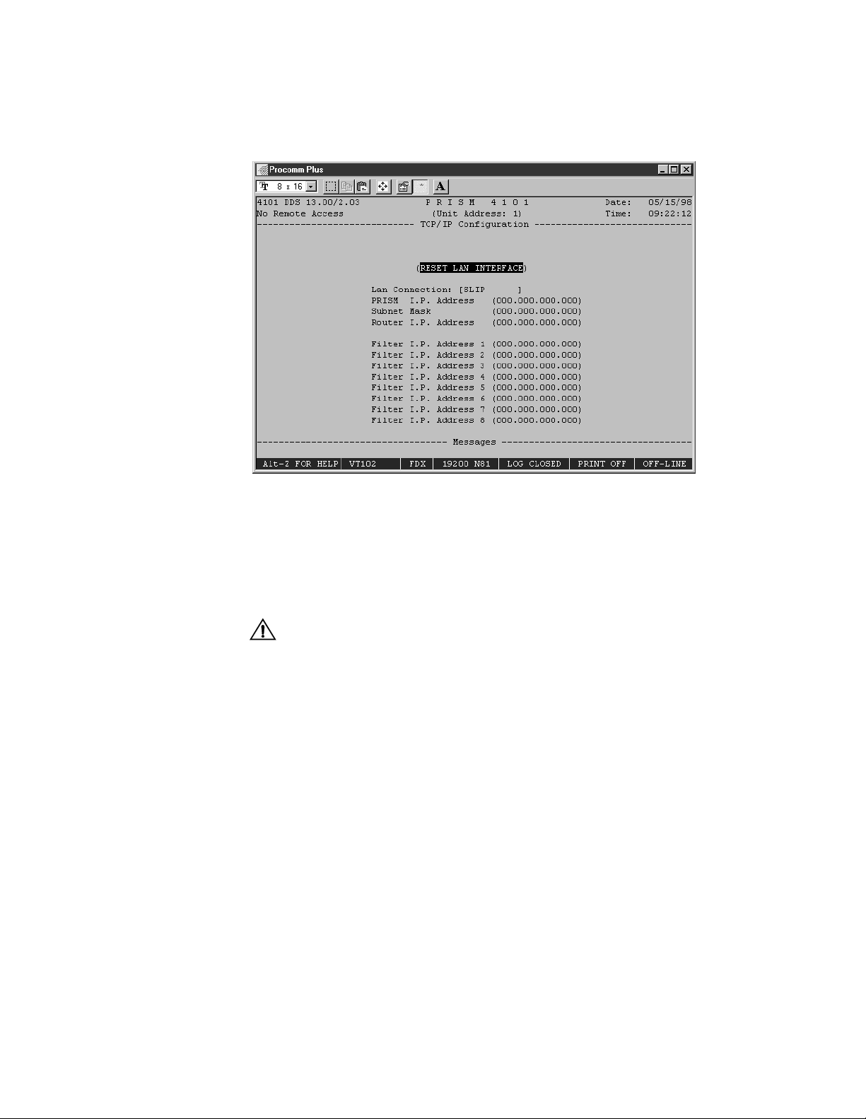
42 C
HAPTER
4: T
ERMINAL INTERFACE
TCP/IP Configuration
The TCP/IP Configuration screen (Figure 4-11) is accessible for the SLIP, Ethernet
or Token Ring SNMP interface. Required parameters are entered for proper
operation with an Ethernet, SLIP or Token Ring based LAN manager.
Figure 4-11
Reset LAN Interface. For changes to unit IP, router IP, subnet mask, and LAN
TCP/IP Configuration Screen
connection to take effect, the unit must be restarted. Pressing Return on this field
brings up a confirmation screen which asks whether or not to proceed with the
reset.
Selecting t his comman d will disr upt dat a serv ice.
LAN Connection.
This field allows you to toggle the different types of interfaces
available. The c hoices a re SLIP, Ethernet, and Toke n Ring. An addi tonal field for
entering desired speed appears next to the LAN connection field when SLIP or
Token Ring is select ed.
SLIP - The choices are 1.2, 2.4, 9.6, 19.2 kbps.
Token Ring - The choices are 4 and 16 Mbps.
PRISM IP Address. This field accepts IP addresses. Each device connected to the
LAN is required to have a unique IP address identifier. This fiel d contains four
3 - digit numbers (or octets) separated by periods. The range of each octet is 0 to
255.
Subnet Mask. This field allows you to manua lly override the subn et mask settin g
which is otherwise discovered by the SNMP agent. This fi eld contains four 3-digit
numbers (or octets) separated by periods. The range of each octet is 0 to 255.
Page 55

Main Menu 43
Router IP Address. This field accepts the IP address of the default router, if one is
present. This field contains four 3-digit numbers (or octets) separated by periods.
The range of each octet is 0 to 255.
Filter IP Address. This field accepts the IP address of the source packet filter. If
any of these fields are set, access is allowed only by the specified IP addresses.
This field contains four 3 - digit numbers (or octets) separated by periods. The
range of each octet is 0 to 255.
SNMP Parameters
The SNMP Configuration screen (Figure 4-12) is accessible for the SLIP, Ethernet
or To ken Ring SNM P interfa ce. It a llows for th e entr y of tho se pa ramete rs requ ired
for proper operation with an Ethernet, SLIP, or Token Ring-based LAN manager.
Figure 4-12
SNMP Configuration Screen
The unit supports alarm reporting by SNMP Traps when running the LAN or SLIP
interface. If the unit’s IP connection is LAN or DIRECT SLIP, it expects the
connection to always be present and thus outputs its Trap messages immediately. If
the IP Connection is DIAL SLIP, the unit dials out from the modem connected to
the SLIP port using the number programmed in the Management Ports screen and
outputs Trap messages upon modem connection.
The PRISM 4101 management capabilities are expanded by the inclusion of the
TxPORT MIB and the ent erprise DDS MIB. Objects in these MIBs ar e listed in
Appendix A. The unit also supports a single telnet session.
Sets. This field can enable SNMP SET commands. Refer to Appendix A for
detailed information on these responses. The choices are ENABLE
Trap IP Address. This field accepts the IP address of a network device to which
and DISABLE.
alarm reporting Traps are to be sent. The unit detects and reports alarms and
provides several options for reporting them, one of which is SNMP Traps. When
Page 56

44 C
HAPTER
4: T
ERMINAL INTERFACE
an alarm occurs, the unit sends a Trap message to up to six destinations on the
user’s network. The Tr ap message is formatted per RFC 1157. The generic Trap
type is enterpri seSpecific (generic - trap = 6).
Up to six Trap IP addresses can be assigned to report via SNMP. The unit reports
each alarm by transmitting an SNMP Trap to each Trap IP address. Network
problems often cause more than one alarm type. In these cases, multiple Trap
messages are generated, each with a different specific Trap type. The specific -trap
field of each Trap message is set to one of the values shown in Appendix A.
Read Community. This display accepts a character string (up to 58 characters)
identifying the group authorized to perform read operations. The default setting is
public
Write Community. This display accepts a character string (up to 58 characters)
identifying the group authorized to perform write operations. The default setting is
‘ ’, which is a null string.
System Contact. This display accepts a character string (up to 58 characters)
identifying the person responsible for a network device. The default setting is no
system contact.
.
System Name. This display ac cepts a charac ter string (up to 58 characters )
identifying the functionality of the network device. The default setting is no
system
name.
System Location. This display accepts a character string (up to 58 characters)
identifying the physical location of network device. The default setting is no
system location.
Page 57

Main Menu 45
Management Ports
The Management Ports screen (Figure 4-13) sets the following parameters for the
Call On Alarm (COA) connection on both the SUPV and SLIP ports.
Figure 4-13
COA Connection (S
Management Ports Screen
). This field controls the remote alarm reporting. ASCII
UPV
alarm reporting through the supervisory port is independent of Trap alarm
reporting on the SLIP port. The ASCII alarm report type is set by the foll owing
choices:
DISABLED
- Alarm reporting is disabled.
DIRECT - Sends reports to a printer or terminal connected directly to the SUPV
port.
DIAL - Sends reports through an attached AT command set com patible modem
connected to the SUPV serial port, which must dial out to a remote modem. The
message format is described in the ELEMENT ID field.
Primary Dial String. This field is an ASCII st ring for the pr imary call on a larm
phone number used in the DIAL mode. The string must include the ATDT
command prefix (ex. ATDT555-1212). The unit attempts three times to connect
using the primary number. If all three attempts fail, it will attempt three times to
connect using the secondary number (if it is not blank). If the secondary number
fails, the unit wai ts five minutes and then atte mpts to comm unicate with th e
primary number again. If a connection is not detected, the unit outputs a
notification message and then disconnects.
Secondary Dial String. This field is an ASC II st ring for the se con dary cal l on al arm
phone number used in the DIAL mode. The string must include the ATDT
command prefix (ex. ATDT555-1212). If the unit could not connect using the
primary number, it will attempt three times to connect using the secondary number
(if it is not blank). If the secondary number fails, the unit waits five minutes and
Page 58

46 C
HAPTER
4: T
ERMINAL INTERFACE
then attempts to communicate with the primary number again. If a connection is
not detected, the unit outputs a notification message and then disconnects.
Initialization String. The modem initialization string is entered in this field. Refer
to the modem’s documenta tion for furthe r informati on. The default se tting is
ATEQ0V1.
Disconnection String. This field identifies the character string to be output when
the modem session is terminated. The default setting is ATH0.
SLIP Port Rate. This field sets the bit rate for the SLIP port. The choices are 1.2,
2.4, 9.6, and 19.2 kbps
SLIP Connection. This field controls rem ote alarm repo rting. Trap reporti ng
through the SLIP port is independent of ASCII alarm reporting through the SUPV
port. The ASCII alarm report type is set by the following choices:
.
DISABLED
- Trap reporting is disabled.
DIAL - Sends traps through modem to SLIP server.
DIRECT - Sends traps directly to the SLIP server.
Primary Dial String. This field is an ASCII st ring for the pr imary call on a larm
phone number used in the DIAL mode. The string must include the ATDT
command prefix (ex. ATDT555-1212). The unit attempts three times to connect
using the primary number. If all three attempts fail, it will attempt three times to
connect using the secondary number (if it is not blank). If the secondary number
fails, the unit wai ts five minutes and then atte mpts to comm unicate with th e
primary number again. If a connection is not detected, the unit outputs a
notification message and then disconnects.
Secondary Dial String. This field is an ASCII string for the secondary call on
alarm phone number used in the DIAL mode. The string must include the ATDT
command prefix (ex. ATDT555-1212). If the unit could not connect using the
primary number, it will attempt three times to connect using the secondary number
(if it is not blank). If the secondary number fails, the unit waits five minutes and
then attempts to communicate with the primary number again. If a connection is
not detected, the unit outputs a notification message and then disconnects.
Initialization String. The modem initialization string is entered in this field. Refer
to the modem’s documenta tion for furthe r informati on. The default se tting is
ATEQ0V1.
Dial Backup
Parameters
Compressed SLIP. The choices are AUTO, ENABLE, and DISABLE. The AUTO
setting allows the unit to negotiate with the far end to enable or disable SLIP
compression, depending on the type of connection.
This unit offers a method of providing an alternate data path when the DDS
network connection fails. This alternate data path is established across a switched
Page 59

Main Menu 47
circuit such as PSTN or ISD N line. The Di al Backup sc reen (Figur e 4-14) allows
you to configure th e DBU paramete rs.
Figure 4-14
DBU Parameters Screen
Status
Shows the current state in the lef t brackets and th e programmi ng choices in th e
right brackets.
DISABLED - DBU has been disallowed via the Command field.
ENABLED - The DBU is allowed but is not currently needed.
DISALLOWED - The DBU has been set for ENABLE DAILY but the current time
is outside of the allowed window specified by the DBU Activation Periods fields.
DIALING, CONNECTING - Establishment of the DBU is in progress.
ANSWERING - The unit is waiting for the other end to call it.
ACTIVE - The DBU is currently active.
Command
The available DBU commands are as follows:
DISABLE - DBU is disabled.
ENABLE - The DBU will activate when the DDS line fails.
ENABLE DAILY - The DBU will only activate if the time is set in the DBU
Activation Periods.
ACTIVATE - Manually activates the DBU function.
Activator
This field allows you to select the criteria the unit uses to activate the dial backup
sequence. T he choices a re LOS
, OOS, OOF, or ANY alarm thresholds.
Page 60

48 C
HAPTER
4: T
ERMINAL INTERFACE
Format / Rat e
These fields allow you to set the data form at and line rate used between th e unit
and the DBU device after connection is established. The Sync format is usually
used with ISDN terminal adapters at 56 kbps or 64 kbps. The Async format is
usually used with st andard modems.
The second field allows you to select a dial backup rate of 2.4, 4.8, 9.6, 19.2
, 38.4,
or 57.6 kbps. Available rates and formats depend on the type of modem used or if
a terminal ada pter is used.
Mode
This field allows you to se lect the call res ponse mode th at the unit will us e. If set
to ORIGINATE, the unit initiates a call when needed. If set to ANSWER, it only
answers an incoming call. If set to CALLBACK ORIGINATE, calls the
pre-defined number, issues a password, hangs up and then waits for the other end
to call back. A fter the pass word is delivered in the se cure mode, t he unit is in
ANSWER mode only. If the setting is CALLBACK ANSWER, the unit waits for a
call and password from the CALLBACK ORIGINATE unit.
Dial String #
This field is used to enter the telephone number (up to 30 characters) that the unit
will call. This is a don't care field when the Dial Backup Mode is ANSWER. This
string must include the ATDT command prefix.
Initialization String
The modem initialization string (up to 30 characters) is entered here. See the
modem docum entation for further informa tion. The defau lt setting is AT &F
.
Disconnection String
Identifies the character string (up to 30 characters) to be output when the modem
session is te rminated. The default settin g is ATH0
.
Reset String (1-5)
This field allows you to enter addition al initializ ation comman ds to be sent in th e
event of a DBU failure. In order to reduce the average DBU connection time,
commands are not sent at every DBU attempt. Consult the external DBU device
manual for fu rther comma nds.
Activation Periods
This field allows you to select the time of day that the Dial Backup option is
allowed to place a backup call. The selections for these fields are 0 to 24. The
selections can be scrolled through by pressing the space bar. A setting of [00] [24] means that the unit will call out anytime there is an alarm condition on the
network. Setting the first field to 8, for a day, and the second field to 17 allows
Dial Backup operations from 8:00 a.m. to 5:00 p.m. of that day. A setting of
[00]-[00], [24]-[24] (or any matching start and end times) will disable DBU for
that day.
Page 61

Main Menu 49
The DBU command must be set to Enable Daily to enable the daily activation
✍
periods.
Summary Screen The Sum mary screen (Figure 4-15) is a display - only screen summarizing the unit
configuration including stored memory. The current column displays the current
unit configuration. The saved column displays the configuration stored in memory.
Figure 4-15
Configuration Item
This list displ ays the items b eing summa rized for review. All items are accessible
though the Configuration screens.
Current
This list displays the current settings for the unit. Upon a power cycle, these
settings may be lost if they are not stored as the saved settings
Saved
This list displays the stored settings. The unit wil revert to these settings upon a
power cycle.
Other Information
This list displays the address and port type information concerning the unit.
Summary Screen
Page 62

50 C
4: T
HAPTER
ERMINAL INTERFACE
Utilities The Utilities screen (Figure 4-16) handles the functions described in the following
paragraphs.
Figure 4-16
Utilities Screen
Element ID
This field allows you to enter an ASCII string (29 characters in length) identifying
the unit to the device receiving the alarm notification messages. Call on alarm
(COA) messages are re ported in the fo llowing format in the DIAL or DIR ECT
modes only.
Element ID <CR> <LF>
NET Alarms: alarms <CR> <LF>
DTE Alarms: alarms <CR> <LF>
where ala rms is a string cons isting of some or all of the ide ntifiers LOS, OO S,
OOF, or the word NONE. The following is an example.
Joesunit
NET Alarms: LOS
DTE Alarms: NONE
The user programmable ELEMENT ID string is transmitted first to allow the COA
function to send a message with a specific meaning to some host (such as a log on
message).
Unit Address
The unit’s address (1 through 250) is displayed and may be changed in this field.
Contrast
Sets the LCD display contrast to a value between zero (high contrast) and 15 (low
contrast). If the contrast value makes the screen appear blank, reset the value for
better viewing.
Page 63

Main Menu 51
Set Time
The current time may be entered in this field using the 24-hour HH:MM:SS
format. For example, 3:45 AM is entered as 03:45:00 and 3:45 PM is entered as
15:45:00. Each field is range checked and automatically limited to the appropriate
range of values.
Set Date
The current date may be entered in this field using the MM/DD/YY format. For
example, July 4, 1998 is entered as 07/04/98. Each field is range checked and
automatica lly limited to th e appropriat e range of values.
New Password
This field allows entry of a password of up to 10 characters. An empty st ring
(carriage return only) may be entered to disable the password feature. After Return
is pressed, the new password is activated and is no longer visible. Therefore, type
carefully when entering a new password and verify before pressing Return. When
the termina l interface is exited and later reactivated, t his passwor d must be entered
exactly to gain access. If the wrong password is entered, the software prompts you
to enter the p assword again. Save the con figuration to reta in the password .
Do not exit the ter minal interface program until the password procedure is fully
understood. If a password has been specified, it must be typed exactly to reenter the
program.
If you program a password and later forget it, contact TxPORT Technical Support
for a one time back door password. Prior written approval must be sent to TxPORT
before the back door password can be issued.
Store Parameters to EEPROM
This comman d causes the un it to store all use r-selectable para meters into
non-volatile memory. These settings then become the saved configuration which
can be loade d at power-up.
This command causes the unit to restar t and will interrupt network traffic. As a safety
procedure, the system will prompt you again if you want to execute this command.
Set to STANDARD mode and store param eters
This command causes the unit (near or far end) to set itself from TXP mode to
STANDARD mode and then store all user-selectable parameters into non-volatile
memory. These settings then become the saved configur ation which can be loaded
at power-up.
This command causes the unit to restar t and will interrupt network traffic. As a safety
procedure, the system will prompt you again if you want to execute this command.
Set to STANDARD mode with DTE tim ing and store
This command causes the unit (near or far end) to set itself from TXP mode to
STANDARD mode, set the clocking to the DTE port, and then store all
user-selectable parameters in to non-volatile me mory. These settings then bec ome
the saved configuration which can be loaded at power-up.
Page 64

52 C
HAPTER
4: T
ERMINAL INTERFACE
Maintenance Reset
This field wil l clear a ll user selectable paramete rs, perfor mance regis ters,
passwords, an d alarms but saves the IP Ad dress. All ala rm threshold parameters
are set to default values. These settings are then written to non-volatile memory as
the saved configuration.
Factory Reset
Clears all use r selectable parameters incl uding the IP A ddress. To exit this screen
without performing the reset function, press the Return key with No selected. To
proceed with the reset function, move the cursor to Yes and press Return. The reset
operation sets all parameters to the factory default settings and zeros all
performance registers.
This comman d caus es the unit to rest ar t an d will i nter rupt networ k traf fic. A s a safety
procedure, the system will prompt you again if you want execute this command.
This comman d caus es the unit to rest ar t an d will i nter rupt networ k traf fic. A s a safety
procedure, the system will prompt you again if you want execute this command.
This comman d caus es the unit to rest ar t an d will i nter rupt networ k traf fic. A s a safety
procedure, the system will prompt you again if you want execute this command.
Page 65

A
MIB R
This appendix describes how the PRISM 4101 embedded SNMP agent conforms
to the RFCs and ente rpriseSpe cific Manageme nt Inform ation Bases .
EFERENCE
Generic MIB Loading Instructions
DDS Network Objects
The MIBs were written using the standard ASN.1 notation. Any standard SNMP
manager should be able to compile the MIBs. Although the exact procedure for loading
MIBs may vary from one platform to another, the following basic steps are the same.
1 The SNMP manager has a directory for MIBs. Copy the files DDS.MIB and
TXPORT.MIB into th is directory. The MIBs are sen t out on a DOS-fo rmatted
diskette, therefore, a DO S2UNIX command may have to be used for UNIX
workstations (typical directories are snmp_m ibs for OpenView
Manager, and mibfiles for Castle Rock SNMPc
2 Start the SNMP manager if it is not already running. Select one of the menu
selections (or selection subheadings) that contains the SNMP MIB operations (this
is Options subheading for HP OpenView and Config subheading for SNMPc).
3 Choose the option for LOADING or COMPILING MIBs. You must specify which
MIBs to load. If the manager only allows one MIB to be loaded at a time, load the
file TXPORT.MIB b efore loa ding the D DS.MIB.
4 Once the manager has successfully loaded the MIBs, you are ready to manage the
TxPORT products. If you have any questions please call TxPORT Product Support.
This section displays the MIB definitions for the object identifier ddsNetConfig
(1.3.6.1.4.1.425.2.2.1).
).
, bin for SunNet
Object Name Object ID User Access Object Description
ddsNetIndex { dds NetConfigEntry 1 } read-only This object is the identifier of the DDS network interfaces on the
managed device.
ddsNetRate { dds NetConfigE ntry 2 } read-write Allows verifying or setti ng the network rate on the nea r-end unit.
ddsNetMode { dds NetConfigEntry 3 } read -write Al lows selecting either standard or propriet ary mode of data transfer.
ddsNetSendCode { dds NetCon figEntry 4 } read - write Allows checking the status of the BERT g enerator or st arting a t est.
ddsNetLoopCon fig { dds NetCon figEntry 5 } read - write Allows enabling a loop or c hecking the status of a loop.
ddsNetStatus { dds NetConfigEntry 6 } read -only Reports current operational status of the network interface.
ddsNetTimingSource { dds NetConfigEntry 7 } read -write Allows selecting or verifying the network timing source.
ddsNetRemComm { dds NetConfigEntry 8 } read -only Reports status of the remote communications link.
Page 66

54 C
HAPTER
EFERENCE
A: MIB R
Object Name Object ID User Access Object Description
ddsNetCircuitAssur { dds NetConfigEntry 9 } read -write Allows enabling or checking the setting of the circuit assurance
option.
ddsNetAntiStrTimer { dds NetConfigEntry 10 } read-write The object is the identifier of the current unit loop mode.
DDS DTE Objects
This section displays the MIB definitions for the object identifier ddsDteConfig
(1.3.6.1.4.1.425.2.2.2).
Object Name Object ID User Access Object Description
ddsDteIndex { ddsDteConfigEntry 1 } read-only This object is the identifier for the DTE interfaces on a managed
ddsDteRate { ddsDteConfigEntry 2 } read-write Allows verifying or selecting the DTE data rate.
ddsDteFormat { ddsDteConfigEntry 3 } read-write This variable describes the current operations format of the DTE
ddsDteParity { ddsDteConfigEntry 4 } read -write Allows verifying or selecting parity when operating in ASYNC
ddsDteStopBit { ddsDteConfigEntry 5 } read -write Allows verifying or setting the Stop Bit setting when in async mode.
ddsDteSendCode { ddsDteConfigEntry 6 } read -write Allows starting a DTE BERT or verifying the setting of the DTE
ddsDteLoopConfig { ddsDteConfigEntry 7 } read -write Allows setting a DTE loop or verifying the status of a DTE loop.
ddsDteStatus { ddsDteConfigEntry 8 } read -only Reports the operations status of the DTE interface.
ddsDteInterfaceType { ddsDt eConfigEntry 9 } read-on ly Reports the DTE interface typ e being used.
ddsDteV54Loop { ddsDteConfigEntry 10 } read -write Allows selecting or verifying the operational state of the V.54
ddsDteRtsCtsDelay { ddsDteConfigEntry 11 } read-write Allows verifying or selecting setting of the RTS-to-CTS delay
ddsDteRtsStatus { ddsDteConfigEntry 12 } read-only Reports the current status of the RTS control lead.
ddsDteCtsStatus { ddsDteConfigEntry 13 } read-only Reports the current status of the CTS control lead.
ddsDteDcdStatus { ddsDteConfigEn try 14 } re ad -on ly R eports the c urrent stat us of the DCD control lead.
ddsDteDtrStatus { ddsDteConfigEntry 15 } read-only Reports the current status of the DTR control lead.
ddsDteDsrStatus { ddsDteConfigEntry 16 } read-only Reports the current status of the DSR control lead.
ddsDteDsrControl { ddsDteConfigEntry 17 } read-write This variable describes the setting for the options on the DTE DSR
ddsDteDcdControl { ddsDteConfigEntry 18 } read -write This variable describes the setting for the options on the DTE DCD
ddsDteRtsControl { ddsDteConfigEntry 19 } read-write This variable describes the setting for the options on the RTS and
ddsDteDtrAlarm { ddsDteConfigEntry 20 } read-write This variable describes the setting for the options on the DTR lead
ddsDteRLDetect { ddsDteConfigEntry 21 } read-write This variable describes the setting for the options on the Remote
ddsDteLLDetect { ddsDteConfigEntry 22 } read-write This variable describes the setting for the options on the Local
ddsDteDteMode { ddsDteConfigEntry 23 } read-write This variable describes the mode inwhich data is being sent from the
device.
interface.
mode.
BERT.
option.
option.
lead (Circuit 107/CC).
lead (Circuit 109/CF).
CTS leads (Circu it 105/C A and 106/C B).
(Circuit 108/CD).
Loopback lead (Circuit 14 0/RLB).
Loopback lead (Circuit 141/LLB).
DDS unit back towards the network.
Page 67

DDS Dial Backup Objects 55
DDS Dial Backup Objects
This section displays the MIB definitions for the object identifier ddsDbuConfig
(1.3.6.1.4.1.425.2.2.3).
Object Name Object ID User Acce ss Object Description
ddsDbuIndex { ddsDbuConfigEntry 1 } rea d-only This object is the ident ifier of the Dial Backup interface on a manag ed
device.
ddsDbuRate { ddsDbuConfig Entry 2 } read-writ e All ows selecting or verifying the Dial Backup rate.
ddsDbuCallMode { ddsDbuConfi gEntry 3 } rea d -write Allows selecting or verify the call response mode.
ddsDbuDataMode { ddsDbuConfigEntr y 4 } read -writ e All ows user to select or verify data mode f or dial backup (sync or
ddsDbuNumber { ddsDbuConfigEntry 4 } read-write Displays the string that allows verifying or setting the dial backup
ddsDbuStatus { ddsDbuC onfigEntry 6 } rea d -only Re ports the c urrent status of the di al backup u nit.
ddsDbuCommand { ddsDbuConfigEntry 7 } read-write This object is the identifier of the current setting that the Dial Backup
ddsDbuActivator { ddsDbuConfigEntry 8 } read-write This object is the identifier of the current trigger that will activate the
ddsDbuInitStr { ddsDbuConfigEntry 9 } read-write This string is the initialization string sent to the dial backup un it before
ddsDbuHangupStr { ddsDbuConfigEn try 10 } read-wri te This string is the ha ngup command string sent to th e dial backup unit
ddsDbuPasswordSt r { ddsDbuConfigEntry 11 } read-write This string is the pro mpt character and password s tring for the dial
ddsDbuSunStart { ddsDbuConfig Entry 12 } read-write This obje ct is the b eginning of an allowable window for Dia l Backup
ddsDbuMonStar t { ddsDbuConfigEntry 13 } rea d-write This object is t he beginnin g of an all owable window for Dial Back up
ddsDbuTueStart { ddsDbuConfig Entry 14 } read-write This obje ct is the b eginning of an allowable window for Dia l Backup
ddsDbuWedStar t { ddsDbuConfigEntry 15 } rea d-write This object is t he beginni ng of an a llowable wind ow for Dial B ackup
ddsDbuThuStart { ddsDbuConfig Entry 16 } read-write This obje ct is the b eginning of an allowable window for Dia l Backup
ddsDbuFriStar t { ddsDbuC onfigEntry 17 } rea d-write This object i s the begin ning of an a llowable wind ow for Dial Backup
ddsDbuSatStart { dd sDbuConfigEn try 18 } read-write This obje ct is the beg inning of an allowable wi ndow for Dia l Backup
ddsDbuSunStop { ddsDbuConfigEn try 19 } read- write This obje ct is the end of an allowable windo w for Dial Backup
ddsDbuMonStop { ddsDbuConfigEn try 20 } read-wri te This object is the end of an allowable windo w for Dial Backup
ddsDbuTueStop { ddsDbuConfigEn try 21 } read- write This obje ct is the end of an allowable windo w for Dial Backup
ddsDbuWedStop { ddsDbuConfigEn try 22 } read-wri te This object is the end of an allowable windo w for Dial Backup
ddsDbuThuStop { dd sDbuConfigEntr y 23 } read-write This object is the end of an allowa ble window for Dial Backup
ddsDbuFriStop { ddsDbuConfi gEntry 24 } rea d-write This ob ject is the end of an allowa ble window for Dial Backu p
ddsDbuSatStop { ddsDbuConfig Entry 25 } read- write This obje ct is the end of an allowable win dow for Dial Backup
ddsDbuResetStr1 { ddsDbuC onfigEntry 26 } read-write This string is one of the dial backup unit’s COLD START
ddsDbuResetStr2 { ddsDbuC onfigEntry 27 } read-write This string is one of the dial backup unit’s COLD START
async).
number.
Unit is operating in.
Dial Backup Unit.
every connection attempt .
after every successful call.
backup unit in Callback DBU.
Activation on Sunday s.
Activation on Monday s.
Activation on Tuesday s.
Activation on Wednesd ays.
Activation on Thursday s.
Activation on Frid ays.
Activation on Saturdays.
Activation on Sunday s.
Activation on Monday s.
Activation on Tuesday s.
Activation on Wednesd ays.
Activation on Thursday s.
Activation on Frid ays.
Activation on Saturdays.
reprogramming strings.
reprogramming strings.
Page 68

56 C
HAPTER
EFERENCE
A: MIB R
Object Name Object ID User Acce ss Object Description
ddsDbuResetStr3 { ddsDbuC onfigEntry 28 } read-write This string is one of the dial backup unit’s COLD START
reprogramming strings.
ddsDbuResetStr4 { ddsDbuC onfigEntry 29 } read-write This string is one of the dial backup unit’s COLD START
ddsDbuResetStr5 { ddsDbuC onfigEntry 30 } read-write This string is one of the dial backup unit’s COLD START
reprogramming strings
reprogramming strings.
Company Information
This section displays the MIB definitions for the object identifier companyInfo
(1.3.6.1.4.1.425.1).
Object Name Obje ct ID User Access Object Description G et
companyName { companyinfo 1 } read-on ly D isplays the company name. “TxPORT”
companyStatement { companyinfo 2 } read -on ly Displays the company visio n statement. “Universal Access to Core
companyStreetAddr { companyinfo 3 } read-only Displays the TxPORT street address. “127 Jetplex Circle”
companyCityState { companyinfo 4 } read-only Displays the location of TxPORT. “Madison, AL”
companyTechService { companyinfo 5 } read-only Displays the Product Support number. “1-800-285-2755”
companyInHouseSales { companyinfo 6 } read-only Displays number which inside sales
can be reached.
companyEmailAddr { companyinfo 7 } read -only Displays the information e-mai l
Product Information
This section displays the MIB definitions for the object identifier productInfo
(1.3.6.1.4.1.425.2.1).
address.
Telecom Services.”
“1-800-926-0085”
“info@txport.com”
Object Name Object ID User Access Object Description Get
productModelNum ber { productInfo 1 } read - only Displays the pro duct model
number for the device cu rrently
being queried.
productModelDesc r { productInfo 2 } read - only Displays a brief descriptio n of
the product.
productElement Id { productInf o 3 } read -onl y Displays the element ID of the
productSoftware Rev { p roductInfo 4 } read -only Displays the software revision of
productHardwareRe v { productInfo 5 } read -only Displays the hardware revision
productSerialNum { productInfo 6 } read-only Displays the unit’s serial
productPhysicalAd dress { prod uctInfo 7 } read-only Displays t he unit’s ph ysical
productNmsAddress { pr oductInfo 8 } read-onl y Displays the unit’s NMS
optionCardDescr { productOption
CardEntry 2 }
optionCardSoftwareRev { productOption
CardEntry 3 }
optionCardHar dwareRev { productOp tion
CardEntry 4 }
optionCardPhysicalAddress { productOption
CardEntry 5 }
read -only Displays a brief description of
read -o nly Displays the software revision of
read -only Displays the hardware revision
read -only Displays the physical address
unit.
the unit.
of the unit.
number.
Ethernet address.
address.
the option card.
the option card.
of the option card.
tied to the option card.
PRISM 4101
CSU / DSU
Returns the unit description.
Returns the unit software revision.
Returns the unit hardware
revision.
Returns the unit serial number.
Returns the MAC for Ethernet or
Token Ring.
Returns 1.
Ethernet option NIC, Token Ring
option NIC, Internal Modem.
Not applicable.
Not applicable.
Not applicable.
Page 69

Definition of Traps 57
Definition of Traps
TxPORT products with SNMP support provide for the detection and reporting of
network alarms. When an alarm occurs, the SNMP agent sends a trap message
(formatted per RFC 1157) to multiple destinations on the user’s network. The
generic trap type is enterpriseSpecific (generic-trap = 7).
Network problems often cause more than one alarm type. In this case, multiple
trap message s are genera ted, each with a different specific-tra p type.
Some alarm types do not apply to cer tain products.
✍
The Trap-PDU has six mandatory fields as shown in the lower level of Figure A-1.
PDU Tag PDU Length PDU Field Value
Enterprise Time StampGeneric Trap #Agent Address VarBindListSpecific Trap #
Figure A-1
The Enterpri se field is compos ed of the Objec t Identifier of the MIB branch
containing the trap definitions. Returns { 1.3.6.1.4.1.425.4 } { txport traps }.
Trap-PDU Format
enterprise Specific Traps
The Agent Address Field is the agent’s IP address unit. This further identifies the
trap sender to the NMS receiving the trap.
The Generic Trap field contains an integer value that represents one of the standard
predefined traps fo r SNMP.
The Specific Trap field contains trap values defined for a particular enterprise. The
values in this field are de fined in the TXPO RT.MIB and the fol lowing tables. The
list is broken down in specific sections to group trap definitions by use.
The Time Stamp field contains the time the trap was generated in the form of time
ticks that have elapsed s ince the agent was initialize d. The value is in un its of
hundredths of a second. ifIndex is typically provided in the Variable Binding List.
The Variable Bindings List contains supplemental implementation information
when includ ed in the Trap-PDU.
This section displays the alarm and description information for the T1 DTE and E1
DTE interface Equipment and Network traps.
Page 70

58 C
HAPTER
A: MIB R
EFERENCE
Equipment Interface
Traps
Network Interface
Traps
This table displays the equipment interface traps for T1 DTE and E1 DTE.
Cleared
Near
Cleared
Far
4 54 104 154 Equipment CRCS threshold exceeded.
5 55 105 155 Equipment BPVS threshol d exceeded.
6 56 106 156 Equipment AISS thresh old exceeded.
7 57 107 157 Equipment YAS threshold exceeded.
8 58 108 158 Equipment UAS threshold exceeded.
9 59 109 159 Equipment OOF S threshold exceeded.
10 60 110 160 Equipment LOSS thr eshold exceeded.
11 61 111 161 Equipment CSS threshold exceeded .
12 62 112 162 Equipment SES thr eshold exceeded.
13 63 113 163 Equipment ES thresh old exceeded .
Alarm
Near
Alarm
Far Description
This table dis plays the netwo rk interface trap s for T1, E1, and DDS.
Cleared
Near
Cleared
Far
14 64 114 1 64 Network CRCS threshold exceeded.
15 65 115 165 Network BPVS thresho ld exceeded.
16 66 116 166 Network AISS thresho ld exceeded.
17 67 117 167 Network YAS threshol d exceeded.
18 68 118 168 Network UAS threshol d exceeded.
19 69 119 169 Network OOFS th reshold exce eded.
20 70 120 170 Network LOSS thre shold excee ded.
21 71 121 171 Network CSS thre shold exceeded .
22 72 122 172 Network SES thre shold excee ded.
23 73 123 173 Network ES thre shold exceede d.
25 75 125 175 Network OOS threshol d exceeded.
28 78 128 178 Port DTR alarm
29 79 129 179 Port ASC alarm
30 80 130 180 Port OOS alarm
31 81 131 181 Port UMC alarm
32 82 132 182 Port TST al arm
33 83 133 183 Port Far-NET al arm
34 84 134 184 Port FAR-DTE alarm
35 85 135 185 Port FAR-Comm unication s alarm
36 86 136 186 Port LOS alarm
37 87 137 187 Port FDL alarm
Alarm
Near
Alarm
Far Description
Page 71

enterprise Specific Traps 59
Data Port Interface
Traps
Other Traps This table displays the miscellaneous interface traps for T1 DTE and E1 DTE.
This table displays the data port interface traps for T1 DTE and E1 DTE.
Cleared
Near
Cleared
Near
Cleared
Far
201 401 601 801 Data Por t 2A DTR Alarm (Port 1 on so me units)
202 402 602 802 Data Port 2B DTR Alarm (Port 2 on some units)
203 403 603 803 Data Por t 3A DTR Alarm (Port 3 on so me units)
204 404 604 804 Data Port 3B DTR Alarm (Port 3 on some units)
205 405 605 805 Data Po rt 4A DTR Alar m
206 406 606 806 Data Port 4B DTR Alarm
207 407 607 807 Data Po rt 5A DTR Alar m
208 408 608 808 Data Port 5B DTR Alarm
209 409 609 809 Data Po rt 6A DTR Alar m
210 410 610 810 Data Port 6B DTR Alarm
Cleared
Far
2 External Alarm
3 103 Communications Err or (8100-specific tr ap)
26 76 126 176 Dial Backup Unit Act ive
27 77 127 177 Dial Backup Unit F ailed
Alarm
Near
Alarm
Near
101 151 Power Failure
Alarm
Far Description
Alarm
Far Description
Page 72

60 C
A: MIB R
HAPTER
EFERENCE
TxPORT and DDS Object Identifier Tree
iso (1) org (3) dod (6) internet (1) private (4) enterprises (1)
txport (425)
companyInfo (1)
companyName (1)
companyStatement (2)
companyStreetAddr (3)
companyCityState (4)
companyTechService (5)
companyInHouseSales (6)
companyEmailA d dr (7)
products (2) temporary (3) traps (4)
productInfo (1)
productModelNumber (1)
productModelDescr (2 )
productElementId (3)
productSoftwareRev (4)
productHardwareRev (5)
productSerialNum (6)
productPhysicalAddress (7)
productNMSAddress (8)
productOptionCardT abl e (9 )
optionCardIndex (1)
optionCardDescre (2)
optionCardSoftwareRev (3)
optionCardHardwareRev (4)
optionCardPhysicalAddress (5)
ddsNetConfig (2)
ddsNetConfigTable (1)
ddsNetIndex (1)
ddsNetRate (2)
ddsNetMode (3)
ddsNetSendCode (4)
ddsNetLoopConfig (5)
ddsNetStatus (6)
ddsNetTimingSource (7)
ddsNetRemComm (8 )
ddsNetCircuitAssur (9)
ddsNetAntiStrTimer (1 0)
ddsDteConfigTable (2)
ddsDteIndex (1)
ddsDteRate (2)
ddsDteFormat (3)
ddsDteParity (4)
ddsDteStopBit (5)
ddsDteSen dCode (6)
ddsDteLoopConfig (7)
ddsDteStatus (8)
ddsDteInterfaceType (9 )
ddsDteV54Loop (1 0)
ddsDteRtsCtsDelay (11)
ddsDteRtsStatus (12)
ddsDteCtsStatus (13)
ddsDteDcdStatus (14)
ddsDteDtrStatus (15)
ddsDteDsrStatus (16)
ddsDteDsrControl (17)
ddsDteDcdControl (18)
ddsDteRtsControl (19)
ddsDteDtrAlarm (20)
ddsDteRLDetect (21)
ddsDteLLDetect (22)
ddsDteDteMode (23)
revision (5)
ddsDbuConfigTable (3)
ddsDbuIndex (1)
ddsDbuRate (2)
ddsDbuMode (3)
ddsDbuFormat (4)
ddsDbuNumber (5)
ddsDbuStatus (6)
ddsDbuCommand (7)
ddsDbuActivator (8)
ddsDbuInitStr (9)
ddsDbuHangupStr (1 0)
ddsDbuPasswordStr (11 )
ddsDbuSunStart (12)
ddsDbuMonStart (1 3)
ddsDbuTueStart (1 4)
ddsDbuWedStart (15)
ddsDbuThuStart (1 6)
ddsDbuFriStart (17)
ddsDbuSatStart (1 8)
ddsDbuSunStop (19)
ddsDbuMonStop (20)
ddsDbuTueStop (21)
ddsDbuWedStop (22)
ddsDbuThuStop (23)
ddsDbuFriStop (24)
ddsDbuSatStop (25)
ddsDbuResetStr1 (26)
ddsDbuResetStr2 (27)
ddsDbuResetStr3 (28)
ddsDbuResetStr4 (29)
ddsDbuResetStr5 (30)
Page 73

B
C
USTOMER
TxPORT provides easy access to customer support information through a variety
of services. This section describes these services.
S
ERVICE
Support from Your Network Supplier
Support from TxPORT
Telephone To speak directly with a TxPORT customer service representative, you may dial
If assistance is required, contact your network supplier. Many suppliers are
authorized TxPORT service partners who are qualified to provide a variety of
services, including network planning, instal lation, hardware maintenance,
application training, and support services. When you contact your network supplier
for assistance, have the following information ready:
✦
Diagnostic error messages
✦
A list of system hardware and software, including revision levels
✦
Details about recent configuration changes, if applicable
If you are unable to receive support from your network supplier or want to contact
us directly, TxPORT offers worldwide customer support 24 hours a day, 7 days a
week by telephone, E-mail, and Worl d Wide Web.
one of the following numbers.
✦
Sales and Marketing: 888 - 4TxPORT
✦
Technical Support
✦
Local: (256) 772- 3770
:
800-285-2755
E-mail You can request sales and marketing information or pose a technical support
question about your TxPORT product with direct e-mail access.
✦
Sales and Marketing: info@txport.com
✦
Technical Support: support@txport.com
World Wide Web Access the latest networking information on TxPORT’s World Wide Web site by
entering our URL into your internet browser.
http://www.txport.com/
This service features information about TxPORT products, customer service,
technical support, latest news releases, and more.
Page 74

62 A
PPENDIX
B: C
USTOMER SERVICE
Ordering Information
Each PRISM 4101 unit is equipped with a V.35 and RS-232D data port
(F-4101-001-1111 is the default part number). You may order you unit with the
optional equipment listed in Table B-1. The optional Ethernet or Token Ring LAN
interface cards may be factory or customer installed into any PRISM 4101 model.
Also provided in yourshipment is an 8-pin modular to 8-pin modular (four twisted
pairs) network cable (9 - 1001 -004-010), a reference manual (34-00230) and a
configuration guide (45-00137).
Table B-1
F-4101-001--11CD
F-3100-100--111 Single Ethernet Card
F-3100-200--111 Single Token Ring Card
PRISM 4101 Ordering Numbers
PRISM 4101
C
0
1
2
D
1
2
3
SNMP Option
SLIP
Ethernet
Token Ring
Dial Backup Option
RS-232 Backup
Internal V.32 Modem
Backup
Internal ISDN
Optional Equipment
You may also require optional equipment for the installation and operation of the
unit. Table B-2 lists the available options for the PRISM 4101.
Table B-2
9-1001-070-xxx
9-1544-619-xxx
9-1001-004-xxx
9-1001-110-xxx 8-pin to 6-pin DBU to ISDN interface
9-1001-052-xxx
9-1001-053-xxx
9-1001-086-xxx
9-1001-211-xxx
9-1001-212-xxx
9-1001-044-xxx
Option Equipment for the PRISM 4101
Network Cables
DDS cross-over kit
Network
LAN interface
Dial Backup Cables
V.35 Cables
DB-25 to Winchester 34-pin male to male, straight through
DB-25 to Winchester 34-pin male to female, straight through
DB-25 to Winchester 34-pin male to male, null modem
RS-232 Cables
DB-25 to DB-25 male to male, straight through
DB-25 to DB-25 male to female, straight through
DB-25 to DB-25 male to male, null modem
*xxx denotes the cable length (in feet).
Page 75

Returning Product s 63
Table B-2
9-1001-072-1
9-1001-073-2
9-1001-091-1
9-1001-091-2
9-1001-015-1
9-1001-015-2
9-1001-016-1
9-1001-016-2
9-1000-1000-1
9-1000-4000-1
Option Equipment for the PRISM 4101
Cable Kits
8-pin RJ-48 to IBM Type 1(Token Ri ng)
DB-9 female to 8-pin RJ-48 (PC to SUPV)
8-pin RJ-48 to DB-2 5 male (modem t o SUPV)
8-pin RJ-48 to DB-2 5 female (modem to SUPV)
Adapters
DB-25 male to 8-pin (modem to SUPV)
DB-25 female to 8-pin (modem to SUPV)
DB-25 male to 8-pin (ter minal to SUPV)
DB-25 female to 8-pin (terminal to SUPV)
MIBs
TxPORT MIB
DDS MIB
Rack Mount Kits
Returning Products
9-3100-002-1
9-3100-002-2
19-inch
23-inch
If for any reason you must return your TxPORT product, it must be returned to the
factory, shipping prepaid and packaged to the best commercial standard for
electronic equipment. TxPORT will pay shipping charges for delivery on return.
You are responsible for mode and cost of shipment to TxPORT.
You must have a Return Ma terial Author ization (RMA ) number marked on the
shipping package. Products sent to TxPORT without RMA numbers will be
returned to the sender unopened, at the sender’s expense. A product sent directly to
TxPORT for repair must first be assign ed a Return Material s Author ization (R MA)
number.
You may obtain an RMA number from customer service at 888-4TxPORT
extension 2282. When calling TxPORT for an RMA, please have the following
information available.
✦
Model number and serial number for each unit.
✦
Reason for return and symptoms of problem.
✦
Warranty status (if known).
✦
Purchase order num ber to cover charges for out - of -warranty items.
✦
Name and phone number of person we can contact if we have questions about the
unit(s).
Page 76

64 A
PPENDIX
B: C
USTOMER SERVICE
✦
Mode of shipment required (second-day air is the normal mode of shipment for all
returned m aterial u nless oth erwise sp ecified).
Units being returned to TxPORT should be sent to the following address.
TxPORT
127 Jetplex Circle
Madison, Alabama 35758
Page 77

I
NDEX
65
A
Acknowledgment
ALARM 11
Alarm Connection 3
Alarm Parameters 16, 41
ii
B
BERT 21
C
Call On Alarms (COA) 45, 46
Canadian Emissions Requirements iii
Configuration 49
Copyright ii
Cursor 13, 29
Customer S ervice 61
D
Data Loop 33
Date / Time 28
Device Ty pe and Revision 28
Diagnostics 3, 20
Dial Connection 7
Direct Connection 7
Documentation Disclaimer ii
DTE Alarms 31
F
Factory Reset
FCC Requirements ii
Field Types 29
Front Panel Buttons 11
Front Panel LEDs 11
52
I
Interface A ccess 27
Interface Conventions 12, 28
L
LAN 5
LAN Port 42
Line Configuration 36
Line Loop 33
Local Loop 34
Loss of Signal Seconds 31
M
Main Menu 29
Maintenance Reset 52
Maintenance Reset 51
Management Ports 45
Menu Element 13
Menu Title 13, 28
Messages 28
E
Element ID 28
Element ID 50
E-mail 61
Ethernet 6
Exit 11
N
Network Configuration 35
Network Connection 2
O
Optional Equipment 62
Ordering Information 62
Page 78

66
Out of Frame Seconds 31
Out of Service Seconds 31
P
Password 25, 51
Port Connections 5
Port Parameters
POWER 11
Power Connection 3
37
R
Reset Alarm Registers 31
Returning Products 63
S
Scroll 11
Select 12
SLIP 6
SLIP Compression 46
SNMP Configuration 43
SNMP Set Comman d 19, 43
Specifications 2
STANDARD WARRANTY SERVICE iv
Status Indications 35
Subnet Mask 19, 42
Supplied Materials 5
Support from TxPORT 61
Support from Your Network Suppl ier 61
SUPV 7
System Utilities 23
T
TCP/IP Parameter s
Telephone 61
TEST 11
Testing
Timing Source 16, 37
Token Ring 6
Trademarks ii
TRAP IP Address 43
Trap IP Address 19
32
42
U
Unit Components 5
Unpacking and Inspection 5
V
V.54 Loop 33
W
World Wid e Web 61
 Loading...