

Page 1

PRISM 3101/3102
T1/FT1 CSU/DSU
®
TRANSPORT
34-00212
rd
Edition
3
i
Page 2

Copyright
©1996 TxPORT. All rights reserved. No part of this publication may be reproduced, transmitted, transcribed, stored in a retrieval
system, or translated into any language in any form by any means without the written permission of TxPORT.
Reorder # 34-00212
rd
Edition, August 1996
3
TxPORT shall not be liable for errors contained herein or for incidental or consequential damages in connection with the furnish-
ing, performance, or use of this material. TxPORT reserves the right to revise this publication from time to time and make
changes in content without obligation to notify any person of such revision changes.
Contents of this publication may be preliminary and/or may be changed at any time without notice and shall not be regarded as a
warranty.
Documentation Disclaimer
TxPORT makes no representation or warranties of any kind whatsoever with respect to the contents hereof and specifically disclaims any implied warranties of merchantability or fitness for any particular purpose.
Acknowledgment
The software used in the SNMP function of this product contains material derived from the following source:
Copyright 1989 by the Regents of the University of California. All rights reserved.
Redistributions in binary form must reproduce the above copyright notice, this list of conditions, and the following disclaimer in
the documentatio n and/or other materials provided with the distributi on. All advert ising mate rials mentio ning featu res or use o f
this software must display the following acknowledgment:
This product includes software developed by the University of California, Berkeley and its contributors.
Neither the name of the University nor the names of its contributors may be used t o endorse or promote produc ts derived from
this software without specific prior written permission.
This software is provided by the regents and contributors ‘as i s’ and any express or implied war ranties, includ ing,
but not limited to, the implied warranties of merchantability and fitness for a particular purpose are disclaimed. In
no event shall the regents or contributors be liabl e for any direct, in direct, incidental, special, exempl ary, or consequential damages (including, but not limited to, procurement of substitute goods or services; loss of use, data, or
profits; or business interruption) however caused and on any theory of liability, whether in contract, strict liability,
or tort (including negligence or otherwise) aris ing in any way out of the use of this software, even if advised of the
possibility of such damage.
ii
Page 3

Table of Contents
1. General
Features . . . . . . . . . . . . . . . . . . . . . . . . . . . . . . . . . . . . .1-1
Specifications . . . . . . . . . . . . . . . . . . . . . . . . . . . . . . . . .1-2
Network Interface . . . . . . . . . . . . . . . . . . . . . . . . .1-2
Equipment Interface . . . . . . . . . . . . . . . . . . . . . . . .1-2
Management Interfaces . . . . . . . . . . . . . . . . . . . . .1-2
Diagnostics . . . . . . . . . . . . . . . . . . . . . . . . . . . . . . .1-2
Alarms . . . . . . . . . . . . . . . . . . . . . . . . . . . . . . . . . . .1-2
Mechanical . . . . . . . . . . . . . . . . . . . . . . . . . . . . . . .1-2
Environmental . . . . . . . . . . . . . . . . . . . . . . . . . . . . .1-2
Standards . . . . . . . . . . . . . . . . . . . . . . . . . . . . . . . . .1-2
Industry Listings . . . . . . . . . . . . . . . . . . . . . . . . . .1-3
FCC Requirements . . . . . . . . . . . . . . . . . . . . . . . . . . . .1-3
Canadian Emissions Requirements . . . . . . . . . . . . . . . .1-3
Warranty . . . . . . . . . . . . . . . . . . . . . . . . . . . . . . . . . . . . .1-3
Ordering Information . . . . . . . . . . . . . . . . . . . . . . . . . .1-4
TxPORT Customer Service . . . . . . . . . . . . . . . . . . . . .1-4
Technical Support . . . . . . . . . . . . . . . . . . . . . . . . . .1-4
Returns/RMA . . . . . . . . . . . . . . . . . . . . . . . . . . . . .1-4
2. Installation
Unpacking and Inspection . . . . . . . . . . . . . . . . . . . . . .2-1
Supplied Materials . . . . . . . . . . . . . . . . . . . . . . . . . . . . .2-1
Rack Mounting . . . . . . . . . . . . . . . . . . . . . . . . . . . . . . . .2-1
Supplied Materials . . . . . . . . . . . . . . . . . . . . . . . . .2-1
Rack Mount Installation . . . . . . . . . . . . . . . . . . . . .2-1
Port Connections . . . . . . . . . . . . . . . . . . . . . . . . . . . . . .2-2
LAN . . . . . . . . . . . . . . . . . . . . . . . . . . . . . . . . . . . .2-2
SLIP . . . . . . . . . . . . . . . . . . . . . . . . . . . . . . . . . . . .2-3
SUPV . . . . . . . . . . . . . . . . . . . . . . . . . . . . . . . . . . .2-3
T1 DTE . . . . . . . . . . . . . . . . . . . . . . . . . . . . . . . . . .2-3
NET . . . . . . . . . . . . . . . . . . . . . . . . . . . . . . . . . . . . .2-4
DBU . . . . . . . . . . . . . . . . . . . . . . . . . . . . . . . . . . . . 2-4
Data Port Connections . . . . . . . . . . . . . . . . . . . . .2-4
Power Connection . . . . . . . . . . . . . . . . . . . . . . . . .2-5
Power Failure . . . . . . . . . . . . . . . . . . . . . . . . . . . . .2-5
Network Management . . . . . . . . . . . . . . . . . . . . . . . . . .2-5
3. Configuration
Hardware Configuration . . . . . . . . . . . . . . . . . . . . . . . . .3-1
Switch S1 . . . . . . . . . . . . . . . . . . . . . . . . . . . . . . . .3-1
Switch S2 . . . . . . . . . . . . . . . . . . . . . . . . . . . . . . . .3-2
Switch S3 . . . . . . . . . . . . . . . . . . . . . . . . . . . . . . . . 3-2
Switch S4 . . . . . . . . . . . . . . . . . . . . . . . . . . . . . . . . 3-3
Software Configuration . . . . . . . . . . . . . . . . . . . . . . . . .3-3
Interface Start-up . . . . . . . . . . . . . . . . . . . . . . . . . . 3-3
Menu Structure . . . . . . . . . . . . . . . . . . . . . . . . . . . . 3-3
Alarms Screen . . . . . . . . . . . . . . . . . . . . . . . . . . . . 3-4
Performance Screen . . . . . . . . . . . . . . . . . . . . . . . . 3-5
Element Maintenance . . . . . . . . . . . . . . . . . . . . . . . 3-6
Configuration Screens . . . . . . . . . . . . . . . . . . . . . .3-9
Line Parameters . . . . . . . . . . . . . . . . . . . . . . . . . . 3-10
Utilities . . . . . . . . . . . . . . . . . . . . . . . . . . . . . . . . .3-17
SNMP / TELNET . . . . . . . . . . . . . . . . . . . . . . . . . . . . 3-18
4. Testing
Hardware Testing . . . . . . . . . . . . . . . . . . . . . . . . . . . . . . 4-1
Front Panel LEDs . . . . . . . . . . . . . . . . . . . . . . . . . .4-1
Front Panel Buttons . . . . . . . . . . . . . . . . . . . . . . . . 4-1
Software Testing . . . . . . . . . . . . . . . . . . . . . . . . . . . . . . 4-1
A. Terminal Interface
Screen Components . . . . . . . . . . . . . . . . . . . . . . . . . . A-1
Cursor Controls . . . . . . . . . . . . . . . . . . . . . . . . . . . . . . A-1
Field Types . . . . . . . . . . . . . . . . . . . . . . . . . . . . . . . . . A-2
Menu Structure . . . . . . . . . . . . . . . . . . . . . . . . . . . . . . A-2
B. Pinout Tables
LAN Port - Ethernet . . . . . . . . . . . . . . . . . . . . . . . . . . .B-1
LAN Port - Token Ring . . . . . . . . . . . . . . . . . . . . . . . . .B-1
SLIP / SUPV Port - PC . . . . . . . . . . . . . . . . . . . . . . . . .B-1
SLIP / SUPV Port - Modem . . . . . . . . . . . . . . . . . . . . .B-1
T1 DTE Port . . . . . . . . . . . . . . . . . . . . . . . . . . . . . . . . . .B-1
NET Port . . . . . . . . . . . . . . . . . . . . . . . . . . . . . . . . . . . .B-1
DBU Port . . . . . . . . . . . . . . . . . . . . . . . . . . . . . . . . . . . .B-1
Data Ports . . . . . . . . . . . . . . . . . . . . . . . . . . . . . . . . . . . .B-2
C. SNMP Agent
RFC 1213 . . . . . . . . . . . . . . . . . . . . . . . . . . . . . . . . . . . .C-1
systemTable . . . . . . . . . . . . . . . . . . . . . . . . . . . . . .C-1
ifTable . . . . . . . . . . . . . . . . . . . . . . . . . . . . . . . . . . .C-1
RFC 1406 - DS1/E1 MIB . . . . . . . . . . . . . . . . . . . . . . .C-2
dsx1ConfigTable . . . . . . . . . . . . . . . . . . . . . . . . . .C-2
dsx1CurrentTable . . . . . . . . . . . . . . . . . . . . . . . . . .C-3
iii
Page 4

dsx1IntervalTable . . . . . . . . . . . . . . . . . . . . . . . . . C-3
dsx1TotalTable . . . . . . . . . . . . . . . . . . . . . . . . . . . C-4
dsx1FarEndCurrentTable . . . . . . . . . . . . . . . . . . . C-4
dsx1FarEndIntervalTable . . . . . . . . . . . . . . . . . . . C-4
dsx1FarEndTotalTable . . . . . . . . . . . . . . . . . . . . . C-5
dsx1FracTable . . . . . . . . . . . . . . . . . . . . . . . . . . . . C-5
iv
Page 5

1. General
TRANSPORT
®
The TxPORT PRISM 3100 Series CSU/DSU terminates a
broad range o f T1/FT1 networking applications. Th e single
port 3101 and the dual port 3102 models integrate voice and
data, LAN-to-LAN networking, or disaster recovery in
either managed or unmanaged environments.
The PRISM 3101 or 3102 may be provisioned through
either switch settings or the terminal interface. The chapters
in this manual are arranged as follows:
1. General - Describes product features, specifications,
FCC and warranty information, in addition to TxPORT
ordering numbers and Customer Service telephone numbers.
2. Install ation - Describes unit mounting, port connections,
and powering.
3. Configuration - Describes hardware and software configuration.
4. Testing - Describes the LED indicators, test buttons, and
procedures for hardware testing from the front panel and
software testing procedures from the unit menu screens.
A. Terminal Interface - Describes all the parts of the unit
menus and their functions.
B. Pinout Charts - Describes the pinout assignments of the
various ports on the unit.
C. SNMP - Describes the SNMP commands and messages.
The PRISM 3101 and 3102 units provide the T1 network
connection through an advanced integral ESF CSU. Full
performance T1 span monitoring allows early detection and
correction of problems before they affect critical applications. The unit provides a wide range of test functions and
loopbacks to aid in rapid fault isolation and repair and also
responds to inband fractional loop codes to accommodate
fractional T1 service testing by the carrier. An internal
BERT allows testing of both the network and equipment
connections.
The PRISM 3101/3102 is compatible with industry standards ensuring access to any T1 provided service and allowing connection of all equipment quickly and correctly. An
innovative design eliminates clocking problems on the high
speed data ports. The unit uses Flash memory allowing firmware upgrades in the field eliminating the need for taking
units out of service for an extended time or returning units
to the factory for updates.
When connecting local area bridging or routing devices to a
T1 network, other CSU/ DSUs are out of the LAN management loop. With the Ethernet or Token Ring management
option, the critical T1 connection point is under control of
the existing SNMP management system, providing seam less
integration of LAN and WAN, and eliminating the need for
a separate CSU/DSU management system.
Features
• Single or dual data ports
• Standard T1 DTE
• Embedded SNMP agent and TELNET software
• Integral ESF/CSU provides full performance monitoring
(meets TR62411, TR54016, and T1.403 standards)
• Complete diagnostic capabilities
• Full T1 software management through
- a VT100 compatible terminal interface
- an embedded SNMP agent
- TELNET sessions
• Programmable alarm thresholds
• Flash memory allows field software upgrades
• DIP configuration switches allow easy installation
PRISM 3100 Series
TEST LOOP
Figure 1-1 PRISM 3101/3102
ALARMTESTBACKUPNET
POWER
General 1-1PRISM 3111/3112
Page 6

• D4 or ESF line framing, AMI or B8ZS line coding
• Supports Fractional T1 services with flexible bandwidth allocation
RS-232 standard SNMP interface
•S
LIP
• Ethernet or T oken Ring NIC for inte gral LAN (optional)
SNMP / TELNET Tok en Ring (optional)
Connection: 8-pin modular
Network Protocol: TCP/IP based networks
Data Rate: 4 or 16 Mbps
Compatibility: Type 3 unshielded twisted pair (UTP)
Specifications
Network Interface
Line Rate: 1.544 Mbps (± 50 ppm)
Line Framing: D4 or ESF
Line Code: AMI or B8ZS
Input Signal: 0 to - 27 dB ALBO
Connection: RJ-48C jack, 100 Ω (± 5%)
Output Signal: 3.0 V (±10%) base-peak into 100 Ω
with protection
Line Build Out: 0, -7.5, -15, -22.5 dB attenuation
Transient Voltage: 1000 V protection, fused input/output
Jitter Control: per TR62411 and T1.403
Timing Source: Internal, recovered line clock,
external DTE
Ones Density: B8ZS, Nx56 bit stuffing, alternate
fill; complies with TR62411
Equipment Interface
DTE Ports: 3101 single port and 3102 dual port
Compatibility: EIA530 (RS-422), female DB-25
CCITT V.35, female 34-pin
Data Rate: Synchronous, Nx56 kbps or
Nx64 kbps (where N = 1 to 24);
independent selection on each port
Clocking: Internal, External, Oversample
Data Invert: Independent selection on each port
Management Interfaces
Supervisory Port
Connection: 8-pin modular (RS-232)
Data Rates: 1.2, 2.4, 9.6, and 19.2 kbps
SLIP Port
Connection: 8-pin modular (RS-232)
Data Rates: 1.2, 2.4, 9.6, and 19.2 kbps
SNMP / TELNET Ethernet (optional)
Connection: 8-pin modular
Network Protocol: TCP/IP based networks
Data Rate: 10 Mbps
Compatibility: 10BASE-T
Diagnostics
Performance: Monitoring per TR54016 and T1.403
Network Loops: Line loopback, payload loopback, or
maintenance loopback in the network
direction
Fractional Loop: Responds to inband V.54 loop code
DTE Port Loops: Bidirectional loop toward DTE and Net
T1 DTE Loops: Line loop toward DTE
Maintenance loop toward DTE
BERT : Multiple test patterns toward network or
DTE ports
Alarms
Activation: Programmable thresholds
Reporting: Front panel LEDs, call out on alarm
(COA), SNMP TRAPs
Power
AC: 117 VAC, 0.12 A, 12 W maximum, 41
BTU maximum
DC: 24 VDC, 0.50 A, 12 W maximum, 41
BTU maximum
48 VDC, 0.25 A, 12 W maximum, 41
BTU maximum
Mechanical
Mounting: Desktop or hori zontal rack
Dimensions: Width 12 inches (30.48 cm)
Height 1.75 inches (53.34 cm)
Depth 9 inches (22.86 cm)
Weight: 4 pounds (1.814 kg)
Environmental
Operating Temp: 32° to 122°F (0° to 50°C)
Storage Temp: -4° to 185°F (-20° to 8 5°C)
Humidity: 95% maximum (non-condensing)
Standards
TR62411: December 1990
TR54016: September 1989
ANSI T1.403: 1989
TR54019A: April 1988
Ethernet: ISO/IEC 8802-3
T oken Ring: ISO/IEC 8802-5
General 1-2
PRISM 3101/3102
Page 7

Internet: RFC1157 (SNMP)
RFC1213 (MIB- II)
RFC1406 (DS1 MIB)
RFC1055 (SLIP)
MIB-II: Device identification and interface per-
formance data. All applicable objects &
reporting traps maintained.
DS1 MIB: DS1 network interface configuration,
performance objects, and alarm
reporting traps are maintained.
Industry Listings
FCC Compliance: Part 15 Subpart B, Class A
FCC Part 68 Cert: Pending at time of printing
UL Listed: Pending at time of printing
IC/CSO3 Cert: Pending at time of printing
FCC Requirements
This equipment has been tested and found to comply with
the limits for a Class A digital device, pursuant to Part 15 of
FCC Rules. These limits are designed to provide reasonable
protection against harmful interference when the equipment
is operated in a commercial environment. This equipment
generates, uses, and can radiate radio frequency energy and
if not installed and used in accordance with the instruction
manual, may cause harmful interference to radio communications. Operation of this equipment in a resid ential area is
likely to cause harmful interference in which case the user is
required to correct the interference at his own expense.
Shielded cables must be used to ensure compliance with the
Class A FCC limits.
Modifications to this unit not
expressly approved by the party
responsible for compliance could void the
user ’s authority to operate the equipment.
This device complies with Part 15 of the FCC rules. Operation is subject to the following two conditions:
1. This device may not cause harmful interference.
2. This device must accept any interference received, including interference that may cause undesired operation.
For users of 1.544 Mbps service,
are provided to ensure compliance with FCC Rules, Part 68.
1. All direct connections to T1 lines must be made using
standard plugs and jacks.
2. The teleph one co mpany may require the following information when applying for leased line facilities.
Port ID: P/N FSG 3XX2/4
REN/SOC: 6.0 N
the following instructions
FIC: 04DU9-BN
04DU9-DN
04DU9-IKN
04DU9-ISN
USOC: RJ-48C
3. If the unit appears to be malfunctioning, it should be disconnected from the telephone lines until you learn
whether the source of trouble is your equipment or the
telephone line. If your equipment needs repair, it should
not be reconnected until it is repaired.
4. The unit has been designed to prevent harm to the T1
network. If the telephone company finds that the equipment is exceeding tolerable parameters, they can temporarily disconnect service. In this case, the telephone
company will give you a dvance notice, if possible.
5. Under FCC rules, no customer is au thor ized to repa ir this
equipment. This restriction applies regardless of whether
the equipment is in or out of warranty.
6. If the telephone company alters their equipment in a
manner that will affect the use of this device, they must
give you advance warning so that you can have the
opportunity for uninterrupted service. You will be
advised of your right to file a complaint with the FCC.
7. In the event of equipment malfunctio n, all repairs shou ld
be performed by our company or an authorized agent. It
is the responsibility of users requiring service to report
the need for service to our company or to one of our
authorized agents.
Canadian Emissions
Requirements
This digital apparatus does not exceed the Class A limits for
radio noise emissions from digi tal apparatus set out in the
Radio Interf erence Regu lations of the Ca nadian D epartmen t
of Communications.
When installing the DC powered version of this
product, use existing 48 VDC battery sources or
a CSA certified power supply.
Le present appareil numerique n’emet pas de bruits radioelectriques depassant les limites applicables aux appareils
numeriques (de la class A) prescrites dans le Reglement sur
le brouillage radioelectrique edicte par le ministere des
Communications du Canada.
Warranty
TxPORT warrants each unit against defects in material and
workmanship for a period of five years from the date the
unit was shipped. If the unit malfunctions at any time during
General 1-3PRISM 3111/3112
Page 8

the warranty period, TxPORT will repair, or at TxPORT’s
option, replace the unit free of charge.
The remedies listed herein are the users sole and exclusive
remedies. TxPORT shall not be liable for any indirect,
direct, incidental or consequential damages. The owner
must return the unit to the factory, shipping prepaid and
packaged to the best commercial standard for electronic
equipment. T xPORT will pay shipping charges fo r delivery
on return. The customer is responsible for mode and cost of
shipment to TxPORT. This warranty does not apply if the
unit has been damaged by accident, misuse or as a result of
service or modification by other than TxPORT personnel.
Ordering Information
The PRISM 3101 is available with a single V.35 or EIA 530
data port (P/N F-3101-001-1111011 is the default). The
PRISM 3102 is available with dual V.35 or EIA 530 data
ports (P/N F-3102-001-1111011 is the default). Ordering
options are listed in Table 1-A using the following format
for a PRISM 3101: F-3101-001--ABCDEFG. To order a
PRISM 3102, substitute 3102 for 3101 in the formula.
Table 1-A Unit Ordering Numbers
Description Option PMI Part #
A Company 1 - TxPORT 9-3101D-001-x
B Special 1
C Voltage 1
D DTE Interf ace 1
E LAN NIC 0
F T1 DTE 1
G DBU 1 - RS-232
*
Not released at time of printing.
- Standard Unit
2 - Hardened Protection
- 110 V
4 - 24/48 VDC
- V.35 Unit
2 - EIA 530 Unit
- Not Installed
1 - Ethernet
2 - Token Ring
- T1 DTE 9-3100-300-1
2 - ISDN
*
*
*
The optional LAN interface cards may be factory or customer installed into a PRISM 3101/3102 using a chassis
mount kit.
Table 1-B Optional Equipment
Part Number Optional Equipment
Mounting Kit
9-3100-002-1 Mounting kit for 19” racks
9-3100-002-2 Mounting kit for 23” racks
Network/T1 DTE Cables
9-1001-004 8-pin mod to 8-pin mod (4 twisted pairs)
9-1001-051-1 T1 cross-over kit, 1 ft.
-----
9-3101D-00x-x
-----
9-3101D-048-x
-----
-----
----9-3100-100-1
9-3100-200-1
-----
9-510-001-1
Table 1-B Optional Equipment
Part Number Optional Equipment
9-1001-006-1
9-1001-006-2
9-1001-073-2
9-1001-073-1
9-1544-619-005
9-1544-619-010
9-1544-619-020
9-1001-015-1 DB-25 Pin/8-Pin Modular Adapter
9-1001-001 V.35 male to male null cable
9-1001-311 V.35 male to male cable
9-1001-312 V.35 male to female cable
9-1001-511N EIA 530 male to male null cable
9-1001-511 EIA 530 male to male cable
9-1001-512 EIA 530 male to female c able
9-1564-037-1 EIA 530 male to RS-449 male cable
9-1564-037-2 EIA 530 male to RS-449 female cable
8-pin mod to 15-pin ‘D’ type adapter, male
8-pin mod to 15-pin ‘D’ adapter, female
Supervisory Cables
UPV
DB-09 female to 8-pin (PC to S
DB-25 female to 8-pin (Modem to SUPV)
8-pin cable, 5 feet
8-pin cable, 10 feet
8-pin cable, 20 feet
V. 35 C ab l es
EIA 530 Cables
)
TxPORT Customer Service
TxPORT office hours are Monday through Friday from 8
a.m. to 5 p.m Central Time. For general, sales and marketing information, contact TxPORT at:
888-4TxPORT Toll Free
800-926-0085 Toll Free
(205) 772-3770 Local
Technical Support
Technical support is available 24 hours a day, seven days a
week. You may contact a support representative by telephone or e-mail.
Toll Free: 1Toll Free:1-800-285-2755
Local: (205) 772- 3770
E-Mail: support@txport.com
Returns/RMA
If for any reason you need to return a TxPORT unit, you
must have a Return Material Authorization (RMA) number
marked on the shipping package. You may obtain an RMA
number from customer service at 888-4TxPORT (or 800-
926-0085), ext. 227.
888-4TxPORT (and after hours emergencies)
General 1-4
PRISM 3101/3102
Page 9

When calling TxPORT for an RMA, please have the following information available.
• Model number and serial number for each unit.
• Reason for return and symptoms of problem.
• Warranty status (if known).
• Purchase order number to cover charges for out - of-warranty
items.
• Name and phone number of person we can contact if we
have questions about the unit(s).
• Mode of shipment required (second-day air is the normal
mode of shipment for all returned material unless otherwise
specified).
Units being returned to TxPORT should be sent to the following address:
TxPORT
127 Jetplex Circle
Madison, Alabama 35758
General 1-5PRISM 3111/3112
Page 10

General 1-6
PRISM 3101/3102
Page 11

2. Installation
Figure 2-1 Rack Mount Installation
This chapter contains instructions for physically installing
the TxPORT PRISM 3101/3102 as either a standalone or
rack mount unit as well as information concerning the communication ports and power supply on the rear of the unit.
Unpacking and Inspection
Upon receipt of your shipment, inspect the shipping container and contents. If the contents of the shipment are
incomplete or, if there is mechanical damage or defect,
notify TxPORT Customer Service. If the shipping container
or cushioning material is damaged, notify the carrier and
TxPORT immediately and make a notation on the delivery
receipt that the container was damaged (if possible, obtain
the signature and name of the person making delivery).
Retain the packaging material until the contents of the shipment have been checked for completeness and the instrument has been checked both mechanically and electrically.
Supplied Materials
Your baseline PRISM 3101/3102 shipment contains three
items.
• PRISM 3101/3102 unit with a captive power supply
• T1 network cable (P/N 9-1544-619-009)
• Reference manual with configuration guides
For specific applications, you may require additional cables
and adapters. Ordering information is located on page 1 -4.
Contact TxPORT Customer Service for further assistance.
Supplied Materials
The 3101/3102 rack mount assembly consists of the following items. Refer to the section Ordering Information on
page 1-4 for ordering numbers.
• A casing supporting the bottom, sides, and rear of the unit.
• 19-inch or 23-inch plate that bolts to rack.
• Set of four bolts and nuts that attach the casing to the plate.
• Four screws that attach the assembly to the 19-inch or 23inch rack.
Rack Mount Installation
1. Insert the PRISM 3101/3102 (rear first) into the casing
as shown in Figure 2-1.
Rack Mounting
The PRISM 3101/3102 is housed in a plastic case intended
for desktop installation. Kits are available which allow the
unit to be mounted into standard 19-inch (33.02 cm) or 23inch (58.42 cm) racks. This assembly occupies two rack
spaces at 3.5 inches (8.89 cm).
Rack mount plate
Four (4) bolts attach
bracket to rack mount plate
115 VAC
60 HZ
SUPVSLIPLAN
S1 S2 S3
Figure 2-2 Rack Mount Assembly (Rear View)
2. Connect this assembly to the 19-inch or 23-inch plate
using the four nuts and bolts as shown in Figure 2- 2.
When the mounting plate is attached to the PRISM 3101/
3102 and the casing, the unit is secure and cannot be
pulled out of the assembly from the front.
S4
T1
DTE
NET
DAT A PORT 2 DATA PORT 1
DBU
Installation 2-1PRISM 3101/3102
Page 12
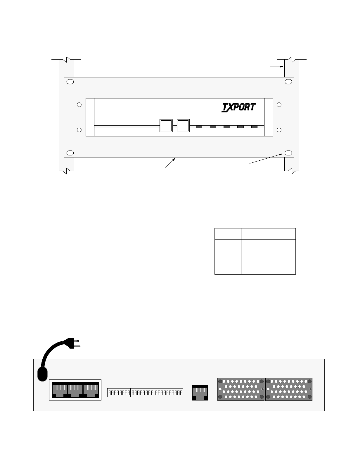
3. To install the rack mount assembly into a rack, tighten
TRANSPORT
®
the four sets of nuts and bolts that attach the plate to the
rack as shown in Figure 2-3.
PRISM 3100 Series
TEST LOOP
Rack
ALARMTESTBACKUPNET
POWER
19" or 23" width available
Figure 2-3 Rack Mount Assembly (Front View)
Port Connections
On the rear of the PRISM 3101/3102, there are several port
connections as shown in Figure 2 -4: LAN, SLIP, SUPV, T1
DTE, NET, DBU, Data Port 1, and Data Port 2.
LAN
The PRISM 3101/3102 can be equipped with either an internal Ethernet or Token Ring network interface card (NIC) for
connection to a local area network (LAN). This port does
not function unless the optional NIC is installed. The
Ethernet interface is 10BASE-T. The Token Ring interface
is Type 3. The connection is an 8-pin modular jack on the
rear of the unit labeled LAN. This allows the NIC to be
installed without changing the rear panel.
The Simple Network Management Protocol (SNMP) agent
can then be programmed to take advantage of the centralized status monitoring and alarm reporting capability of
SNMP managed networks.
Four (4) nuts and bolts
attach rack mount kit to rack
Ethernet: The Ethernet interface complies with standard
twisted pair, 10BASE-T requirements. Table 2-A displays the
pinout assignments for the 8-pin modular LAN connection.
Table 2-A Ethernet Pinout Assignments
Pin Ether net Interface
1 Data Out (+)
2 Data Out (-)
3 Data In (+)
6 Data In (-)
Configure the LAN interface before connecting the PRISM
3101/3102 to the LAN network. See the section
SNMP Configuration on page 3-15 for specific information.
Token Ring: The Token Ring interface is designed to operate on both 4 and 16 Mbps networks and complies with
standard unshielded twisted pair (UTP) requirements. Table
Installation 2-2
115 VAC
60 HZ
SUPVSLIPLAN
11
8
S1 S2 S3
8
110
NET
DATA PORT 2
DATA PORT 1
Figure 2-4 PRISM 3101/3102 Rear Panel (dual port 3102 shown)
PRISM 3101/3102
Page 13

2-B displays the pinout assignments for the 8 - pin modular
LAN connection.
Table 2-B Token Ring Pinout Assignments
Pin Token Ring Interface
3 Data Out (-)
4 Data In (+)
5 Data In (-)
6 Data Out (+)
Configure the LAN interface before connecting the PRISM
3101/3102 to the LAN network. See the section
SNMP Configuration on page 3-15 for specific information.
SLIP
The SLIP port bit rates are configured through Switch S1
(page 3-1). This port is a DCE port configured for 8 bits, no
parity, and 1 stop bit. The physical connections are 8- pin
modular jacks (electrically RS-232). Figure 2-5 provides
the pinout assignments. Refer to the section
Ordering Information on page 1-4 for cable information.
The SLIP port may be used to manage the unit. This port
allows access to the embedded SNMP agent used for trap
reporting or SNMP management. You may access this port
through either a direct connection or a dial-up connection
via an AT command set compatible modem. The modem
should be optioned to ignore DTR, enable auto answer,
inhibit command echo, and return verbose result codes.
Serial bit rates can be set from 9.6 kbps to 56 kbps.
If you call the unit and send the BREAK command before receiving the CONNECT message,
the modem will hang-up.
SUPV
The SUPV port bit rates are configured through Switch S1
(page 3 - 1) and programmed through the Management Ports
menu on page 3 - 16. This port is a DCE port configured for
8 bits, no parity, and 1 stop bit. The physical connections are
8 -pin modular jacks (electrically RS-232). Figure 2- 5 provides the pinout assignments. Refer to the section
Ordering Information on page 1-4 for cable information.
The unit firmware may be accessed through this port (see
Software Configuration on page 3-3) as well as the Call On
Alarm feature (page 3-16). You may access this port
through either a direct connection or a dial-up connection
via an AT command set compatible modem. The modem
should be optioned to ignore DTR, enable auto answer,
inhibit command echo, and return verbose result codes.
Serial bit rates can be set from 1200 bps to 19200 bps.
If you call the unit and send the BREAK command before receiving the CONNECT message,
the modem will hang-up.
T1 DTE
The T1 DTE port bit rates are configured through Switch S4
(page 3-3). The physical connection is an 8-pin modular
jack. Table 2-C provides the pinout assignments. Any channel not mapped to a data port is routed to the T1 DTE interface. T1 DTE port linecoding is not dependent on the
UPV/SLIP
Port
DCD Out 1
CTS Out 2
Frame Gnd 3
Data Out 4
Data In 5
Signal Gnd 6
RTS In 7
DTR In 8
8-Pin
Modular
PRISM 3102 Rear Panel
RS-232 to Terminal
PN# 9-1001-073-2
PC (DTE)S
1 DCD
8 CTS
5 Frame Gnd
2 RXD
3 TXD
NC Signal Gnd
7 RTS
4 DTR
DB-9
UPV/SLIP
Port
DTR Out 1
RT S Out 2
Frame Gnd 3
Data Out 4
Data In 5
Signal Gnd 6
CTS In 7
DCD In 8
8-Pin
Modular
PRISM 3102 Rear Panel
PC
RS-232 to Modem
PN# 9-1001-083-1
Figure 2-5 SUPV and SLIP Terminal/Modem Connections
Modem (DCE)S
20 DTR
4RTS
1Frame Gnd
2 TXD
3 RXD
7 Si gnal Gnd
5CTS
8DCD
DB-25
Modem
Installation 2-3PRISM 3101/3102
Page 14

linecoding of the network interface. ESF to D4 conversion
is supported.
Table 2-C T1 DTE Pinout
Pin T1 DTE Interface
1 Data Out
2 Data Out
3,6 Not Used
4 Data In
5 Data In
7,8 Chassis Ground
NET
The Network interface connection contains an automatic
line build out (ALBO) allowing the unit to be located a substantial distance away from the telco network interface with
a receive signal level down to -27 dB.
The network interface LBO level should be set as instructed
in the Line Parameters section on page 3-10. Maximum
suggested cable lengths for the connection from the unit to
the network are listed in Table 2-D. Calculations are based
on a cable temperature of 70° F, 0.083 uF/mile capacitance,
a 27 dB loss, and a 100 Ω, non-load ed , twisted pair cable.
Table 2-D Maximum Cable Lengths
Cable Type Loss per 1000' Max Cable Length
26-gauge PIC 6.8 dB 4,400 ft
24-gauge PIC 5.4 dB 5,500 ft
22-gauge PIC 4.2 dB 7,100 ft
19-gauge PIC 3.0 dB 10,000 ft
PIC - Plastic Insulated Ca ble
The network physical interface is a standard RJ-48C 8 - pin
modular jack. Table 2-E displays the pinout assignments.
that can connect, through a connector adapter, to a public
switched digital network (PSDN) device such as a TxPORT
PS500. Table 2-F displays the pinout assignments. See page
3-13 for information on DBU parameters and settings.
Table 2-F DBU Port Pinout
Pin Connection
1 Rx Clock In
2DTR Out
3RTS Out
4 Fra m e G round
5 Data Out
6 Data In
7 Signa l Gr ou nd
8CTS In
9 DCD In
10 Tx Clock In
Data Port Connections
The PRISM 3101 is equipped with either a V.35 port (on a
standard 34- pin connector) or with an EIA 530 port (on a
standard 25-pin DB-25 connector). The PRISM 3102 is available with either two V.35 ports or with two EIA 530 ports.
A standard EIA 530 to RS-449 conversion cable may be
used to adapt the DB-25 high speed port connection to 37-
pin RS-449 compatible data equipment. Pin functions for
both high speed port interfaces are listed in Table 2-G.
Default settings route all available DS0s to the T1 DTE port.
FCC rules require that interconnect-
ing cables carrying high speed data
be shielded appropriately in order to minimize radio frequency interference.
Table 2-E Network Interface Pinout
Pin T1 NET Interface
1 Data In
2 Data In
3, 6 Not used
4 Data Out
5 Data Out
7, 8 Chassis Ground
In accordance with FCC Rules, Part
68.218 (b), you must notify the tel ephone company prior to disconnecting
this produ c t.
DBU
The Dial Back-Up (DBU) port provides an alternate path
when the T1 network interface service is disrupted or performance quality is degraded. This port is a 10-pin RS-232 port
Installation 2-4
Table 2-G High Speed DTE Interface
Common Name
Frame Ground 1 A
Transmit Data 2, 14 P, S
Receive Data 3, 16 R, T
Request to Send 4, 19 C
Clear to Send 5, 13 D
Data Set Ready 6, 22 E
Signal Ground 7 B
Data Carrier Detect 8, 10 F
Transmit Clock 15, 12 Y, AA
Receive Clock 17, 9 V, X
Local Loopback 18 J
Data Term Ready 20, 23 H
Remote Loopback 21 BB
Terminal Timing 24, 11 U, W
EIA 530
DB-25
V.35
34-pin
PRISM 3101/3102
Page 15

Power Connection
AC powered units are powered by a 110 VAC captive power
supply. There is no power switch.
DC powered units have two terminal block connections
labeled posit ive (+) and negative (-) that accept wire sizes
from 12-gauge to 20-gauge. Either polarity (positive or negative) may be referenced to ground.
The unit is protected from reverse
power connection but w ill no t op erate until power is properly connected
according to the marked polarities (positive-positive and negative-negative).
Power Failure
The PRISM 3101/3102 provides non-volatile memory
retention of the unit configuration i n cas e of a power failure.
This feature allows the unit to automatically restore normal
service following a power loss. When power is applied to
the unit, the front panel indicators flash for approximately
five seconds as the unit starts up.
Network Management
The PRISM 3101/3102 is compatible with the TxPORT
8100A Site Controller as a remote or ‘far end’ element. The
8100A can be used to manage TxPORT network access
products. Network management is performed through the
SUPV port, SLIP port, or the LAN port.
Installation 2-5PRISM 3101/3102
Page 16

Installation 2-6
PRISM 3101/3102
Page 17

3. Configuration
The PRISM 3101/3102 can be configured through manual
switch settings and/or through a VT100 terminal connection
to the supervisory port.
All default options in this manual are underlined
.
Hardware Co nfi guratio n
Hardware configuration is set using four dual in-line pack age (DIP) switches located on the rear of the unit. These
switches allow you to configure simple applications. Refer
to Figure 3 - 1 for switch locatio ns. A removable configuration guide (45-00103) is included in the back of this manual.
Switch S1
Switch S1 (Figure 3- 2) configures the boot mode, SUPV
Port Bit Rate, SLIP Port Bit Rate, Channel Assignments,
Data Port 1, and Data Port 2. The SUPV and SLIP s witches
(S1-2 through S1-5) cannot be modified through the terminal interface.
Boot
SUPV Port
Bit Rate
SUPV Port
Bit Rate
SLIP Port
Bit Rate
SLIP Port
Bit Rate
Mode
Dn Up
Figure 3-2 Switch S1
Boot Mode: Switch S1 - 1 determines whether the unit configures itself from the DIP switches or from the battery
backed RAM. If set to boot from RAM (Up), the sw itch settings are ignored. If set to boot from switches (Dn)
reads the DIP switches on power-up and configures accordingly. Once running, configuration changes can be made
through the terminal interface, overriding the switch settings.
SUPV Port Bit Rate: Switch S1-2 and S1-3 set the
supervisory port bit rate. This is a serial RS-232 DCE port
Data Port 1
Data Port 2
Rate Multiplier
Channel
Rate Multiplier
Assignment
Switch
7654321
S1
8
, the unit
configured for 8 bits, no parity, and 1 stop bit. Table 3-A
shows the available speeds.
Table 3-A SUPV Port Bit Rate
S1-2 S1-3 SUPV Port Rate
Up Up 1.2 kbps
Dn Up 2.4 kbps
Dn
Up Dn 19.2 kbps
Dn 9.6 kbps
SLIP Port Bit Rate: Switch S1 - 4 and S1 -5 set the SLIP
port bit rate. This is a serial RS-232 DCE port configured
for 8 bits, no parity, and 1 stop bit. Table 3-B shows the
available speeds.
Table 3-B SLIP Port Bit Rate
S1-4 S1-5 SLIP Port Rate
Up Up 1.2 kbps
Dn Up 2.4 kbps
Dn
Up Dn 19.26 kbps
Dn 9.6 kbps
Channel Assignment: Switch S1-6 selects the channel
assignment mode for network T1 DS0s carrying data to the
high speed port. Contiguous channel mode (Dn)
assigns the
channels as a block beginning at channel one for Data Port 1
and the first available channel for Data Port 2, if installed.
For example, if the high speed port data rate is to be 256
kbps (as defined by Switch S3), the unit assigns network
channels one through four to the high speed port.
Alternate (Up) channel mode assigns an idle channel following each data channel. For example, data are carried on
channels 1, 3 , 5, and 7 . Channels 2, 4, 6, a nd 8 are idle (the
idle setting is binary code 01111111). The advantage of
alternate channel assignment is that T1 ones density requirements are maintained by the idle channels rather than placing any restrictions on the high speed data.
Data Port 1: Switch S1 - 7 sets the multiplier for the Data
Port 1 input timing. The unit can operate at any data rate
that is a multiple of 56 or 64 kb ps. Selecting N x 64K
(Dn)
provides port bit rates that are multiples of 64 kbps. The
115 VAC
60 HZ
1
SUPVSLIPLAN
S4
11
8
S1 S2 S3
8
8
110
T1
DTE
NET
DATA PORT 2
DBU
Figure 3-1 PRISM 3101/3102 Rear Panel (dual port 3102 shown)
DATA PORT 1
Configuration 3-1PRISM 3101/3102
Page 18

ones density requirements of the T1 network line must be
Dn Up
10
Switch
S3
Port 1 Bit Rate
Port 2 Bit Rate
Figure 3-4 Switch S3
ensured in this mode. Refer to the section entitled
Line Parameters on page 3-10 for more information.
Selecting N x 56K (Up) allows port bit rates that are multiples of 56 kbps. The unit maintains ones density for the
selected DS0 channel in this mode.
Data Port 2: S witch S1 - 8 sets the multiplier for Data Port
2 on the 3102 only. The unit can operate at any data rate that
is a multiple of 56 or 64 kbps. Selecting N x 64K
(Dn) provides port bit rates that are multiples of 64 kbps. The ones
density requirements of the T1 network line must be
ensured in this mode. Refer to the section entitled
Line Parameters on page 3-10 for more information.
Selecting N x 56K (Up) allows port bit rates that are multiples of 56 kbps. The unit maintains ones density for the
selected DS0 channel in this mode.
Switch S2
Switch S2 (Figure 3 - 3) configures parameters for Network
Framing, Network Coding, Network LBO, Timing Source,
Test Button loop Code, and Test Button Mode.
be optioned to time from an internal standard or from the
high speed data interface as shown in Table 3-D.
Table 3-D Timing Source
S2-5 S2-6 Timing Source
Dn
Up Dn Internal
Dn Up Port 1 EXC
Up Up T1 DTE
Dn Network
Test Button Loop Code: Switch S2-7 selects either an
inband line loopback code (Dn)
or an inband V.54 loop code
(Up) for use with the front panel test button. On the 3102
model, this switch applies to Data Port 1 only.
Test Button Mode: Switch S2-8 selects the test button
operation mode as either BERT (Dn)
or Clear (Up).
Switch S3
Switch S3 (Figure 3-4) sets the Port 1 and Port 2 bit rates as
shown in Table 3-E. Positions S 3-6 through S3 - 10 are not
applicable on the 3101.
Network
Network
Dn Up
Framing
Network
Coding
LBO
Network
LBO
Timing
Source
Test Butto n
Test Butto n
Mode
Timing
Loop Code
Source
Switch
7654321
S2
8
Figure 3-3 Switch S2
Network Framing: Switch S2- 1 matches the unit to the
network line framing as either ESF (Dn)
or D4 (Up).
Network Coding: Switch S2 - 2 sets the network line coding to either B8ZS (Dn)
or AMI (Up).
Network LBO: Switch S2-3 and S2 -4 set the line build
out signal level of the transmit data (TXD) from the unit to
the network. The telephone company can provide the
proper settin g.
If unsure of the exact setting, leave it at the
default value. Table 3-C lists the available levels.
T ab le 3-C Network LBO
S2-3 S2-4 Network LBO
Dn
Up Dn -7.5 dB
Dn Up -15.0 dB
Up Up -22.5 dB
Dn 0 dB
Timing Source: Switch S2 - 5 and S2 - 6 determine the unit
clocking source. The most common timing source for CSU/
DSU applications is the network. The 3101/3102 may also
2 9
8765431
Table 3-E Port 1/Port 2 Bit Rates
S1-7 Up S1-7 Dn S3-1 S3-2 S3-3 S3-4 S3-5
# of
DS0s
Disable
S1-8 Up S1-8 Dn S3-6 S3-7 S3-8 S3-9 S3-10
Disable Dn Dn Dn Dn Dn
1 56 kbps 64 kbps Up Dn Dn Dn Dn
2 112 128 Dn Up Dn Dn Dn
3 168 192 Up Up Dn Dn Dn
4 224 256 Dn Dn Up Dn Dn
5 280 320 Up Dn Up Dn Dn
6 336 384 Dn Up Up Dn Dn
7 392 448 Up Up Up Dn Dn
8 448 512 Dn Dn Dn Up Dn
9 504 576 Up Dn Dn Up Dn
10 560 640 Dn Up Dn Up Dn
11 616 704 Up Up Dn Up Dn
12 672 768 Dn Dn Up Up Dn
13 728 832 Up Dn Up Up Dn
14 784 896 Dn Up Up Up Dn
15 840 960 Up Up Up Up Dn
16 896 1024 Dn Dn Dn Dn Up
17 952 1088 Up Dn Dn Dn Up
18 1008 1152 Dn Up Dn Dn Up
19 1064 1216 Up Up Dn Dn Up
20 1120 1280 Dn Dn Up Dn Up
21 1176 1344 Up Dn Up Dn Up
22 1232 1408 Dn Up Up Dn Up
23 1288 1472 Up Up Up Dn Up
24 1344 1536 Dn Dn Dn Up Up
Configuration 3-2
PRISM 3101/3102
Page 19

Switch S4
Alarms
MAIN
MENU
Log
Off
LogOnPerformance
Maintenance
Configuration
Utilities
Standard 24-Hour
Enhanced 24-Hour
Standard 30-Day
Enhanced 30-Day
Line Parameters
Alarm Parameters
Port Parameters
TCP/IP Parameters
SNMP Parameters
Management Ports
Summary
DBU Parameters
Figure 3-6 Menu Structure
Switch S4 (Figure 3 -5) configures the T1 DTE port. Any
channel not mapped to a data port is mapped to the T1 DTE
port. Linecoding on the T1 DTE is independent of T1
linecoding.
Menu Structure
The terminal interface opens with a main menu allowing
five options: Alarms, Performance, Maintenance, Configuration, and Utilities (Figure 3 - 6). Each menu screen allows
you to access the local or far end menu screen.
Dn Up
DTE
Framing
DTE
Coding
DTE LBO
DTE LBO
DTE LBO
Not Used
Not Used
7654321
Not Used
8
Switch
S4
Figure 3-5 Switch S4
DTE Framing: Switch S4-1 selects the framing type for the
DTE side of the element as either ESF (Dn) or D4 (Up)
.
DTE Coding: Switch S4-2 sets th e DTE side line co ding as
either B8ZS (Dn) or AMI (Up)
.
DTE DSX Level: Switch S4-3, S4-4, and S 4-5 set the DTE
line build-out signal level as identified in Table 3-F.
Table 3-F DTE DSX
S4-3 S4-4 S4-5
0-110 ft
111-220 ft Up Dn Dn
221-330 ft Dn Up Dn
331-440 ft Up Up Dn
441-550 ft Dn Dn Up
551-660 ft Up Dn Up
661 ft > Dn Up Up
Dn Dn Dn
For more information on terminal interface conventions,
refer to Appendix A, Terminal Interface.
If you do not enter a keystroke for
10 minutes, the terminal interface
automatically logs of f.
Software Configuration
The terminal interface is a firmware application program
embedded inside the PRISM 3101/3102. You can access
this information through the LAN port (page 2- 2), SUPV
port (page 2- 3), or SLIP port (page 2- 3) using a TELNET
session.
Interface Start-up
Once a compatible terminal is properly connected to the
unit, you can start a terminal interface session by sending a
BREAK command to the unit (or by pressing <return> four
times). The Main Menu screen is displayed if a password
has not been specified.
If a password has been previously establish, you must enter
the correct password to continue the session. The password
is case - sens itive. If you have forgotten your password, note
the date and time shown on your screen and contact
TxPORT Technical Support. You can establish a password
through the Utilities screen on page 3- 17.
Configuration 3-3PRISM 3101/3102
Page 20

Alarms Screen
The Alarms screen (Figure 3 -7) allows you to view the current alarm status of the network and the DTE lines.
NETAlarms: These status lines display the selected element’s current network signal alarm state (Table 3-G).
Alarms are determined by the selectable thresholds in
Alarm Configuration on page 3-11.
Table 3-G NET Alarm Indicators
Table 3-H DTE Alarm Indicators
Alarm Description
OK No alarm threshold has been exceeded, although
errors may exist which do not exceed thresholds.
OOFS The Out Of Frame Seconds threshold is exceeded.
PORT 1 DTR Alarm on PO RT 1
PORT 2 DTR Alarm on PO RT 2
Alarm Description
------- No status is available
OK No alarm threshold has been exceeded, although
errors may exist which do not exceed thresholds.
ERRS The Errored Seconds, Sev erely Errored Seconds, o r
Bipolar Errored Seconds threshold is exceeded.
LOSS The Loss Of Signal Seconds threshold is exceeded.
OOFS The Out Of Frame Seconds threshold is exceeded.
RAIS The Remote Alarm Seconds threshold is exceeded.
AISS The Alarm Indication Seconds threshold is
exceeded.
UAS The Unavailable Seconds threshold is exceeded.
DBA Dial Backup Active
DBF Dial Backup Failed
PORT 1 DTR Alarm on PORT 1
PORT 2 DTR Alarm on PORT 2
DTEAlarms: These status lines display the selected element’s current DTE signal alarm state (Table 3-H). Alarms
are determined by the selectable thresholds in
Alarm Configuration on page 3-11.
Selectable thresholds in the Alarm Parameters screen and
the DTR Alarm may be enabled or disabled for the ports in
the Port Parameters screen.
(alarm status): The main body of the Alarms screen shows
the current count for parameters that may be used to trigger
an alarm.
The Current column displays a total of the preceding 15
one - minute intervals. At the end of each one-minute interval, the oldest minute of the 15-minute interval is discarded.
The Threshold column displa ys the values set in the Alarm
Configuration screen (page 3-11). Parameters having a current value equal to or greater than its non-zero threshold
generates an alarm. Any parameter with a threshold value of
zero is disabled from generating alarms.
The parameters shown on the Alarms screen are
updated at approximately five second intervals.
Power Loss Seconds: This field displays the number of
seconds that the element has been without power since this
value was last cleared.
Configuration 3-4
Figure 3-7 Alarms Screen
PRISM 3101/3102
Page 21

Reset Alarm Registers: Pressing <return> on (RESET)
zeros the value of all Current alarm parameters, but does not
affect 24-hour or 30-day performance registers.
Performance Screen
The Performance screen (Figure 3-8) display a detailed history of the error parameters that are continuously monitored.
The terminal interface provides a display of near end or far
end performance data using the facility data link.
The unit is equipped with a dual set of performance data
registers that hold line statistics for both the telco and user.
Each register set provides detailed status and performance
history for the network interface.
The system has four Performance screens. The STANDARD
24 HOUR and the ENHANCED 24 HOUR screens allow
the user to view the 24-hour detailed performance history of
the T1 circuit. The only difference in the two screens is in
the type of performance data displayed. The STANDARD
24 HOUR screen is shown in Figure 3-8.
The STANDARD 30 DAY and the ENHANCED 30 DAY
screens allow the user to view a 30-day history of a particular element’s performance. These screens reference intervals
by date rather than by time. To reach each of the four screen
types, use the <spacebar> to toggle the STANDARD 24
HOUR field. The other fields are described as follows:
Element: Pressing the <spacebar> toggles this field for
selection of either the NEAR or FAR unit as the source of
performance data or the target of commands. NEAR refers
to the unit to which the termin al is connected . FAR refers to
the unit at the other end of the network T1 span.
Target: This field selects the display of User or Telco performance registers. Telco registers are for viewing only and
may not be changed. The options are:
[USER] [NET] – Display the user performance registers for
the network.
[TELCO] [NET] – Display the telco performance registers
for the network.
Error Events: This field displays the running total of ESF
error events for the circuit selected in the Element field and
is applicable only when Target is set to [USER ]. This count
accumulates until it reaches 65535 or is reset by pressing
<return> with the (RESET) field highlighted.
Reset Performance Registers: This field allows the element registers to be reset and may only be used when the
Target field is set to [USER]. If <return> is pressed, the following warning appears:
DELETE ALL PERFORMANCE DATA?
(NO!) (YES)
To exit this screen without performing the reset function,
press <return> with NO selected. To proceed with the reset
function, press <return> on YES. All values for the chosen
register set (NET or DTE) are then reset to zero.
[Standard 24 Hour]: Toggling this field with the <spacebar> steps through the four available performance screens.
The remainder of the fields in the Performance screen are
for display only. They are defined as follows:
Status: Displays the selected T1 line status derived from
the type (or absence) of errors in the received data. This status represents the immediate state of the received T1 signal
and is not related to the alarm thresho lds. This field shows
Figure 3-8 Performance Screen
Configuration 3-5PRISM 3101/3102
Page 22
one or more of the signal status conditions listed in
Line Fault and Loop Status on page 3-7.
Completed Days: Displays the number of days which are
included in the 30-day to tals.
Completed Intervals: Displays the number of 15-minute
intervals in the last 24- hour period since the registers were
last cleared (a 24-hour period may contain up to 96 intervals).
24 Hr.% Error Free: Displays the percentage o f error free
seconds within the last 24 hours or since the event registers
were last cleared (based only on the ES and UAS parameters).
(performance data): The main body of display data consists of error events for three different periods: The first display line shows the data accumulated for the current interval
(from 0 to 900 seconds). The second line shows the totals
for the last 24- hour period (or the last 96 fifteen-minute
intervals). The third line shows the 30-day totals.
The remaining lines of this screen show the data for any
intervals containing errors. Interval 1 is the most recently
stored 15-minute interval and interval 96 is the oldest in the
current 24 -hour period. On the 30 - day screens, interval 30
is the oldest 1- day interval in the current 30- day period.
The real time (or date on 30-day screens) of the interval
beginning is shown in the first column.
If more than 5 errored intervals have elapsed, [PAGE- Dn]
appears to the left of the performance data. Pressing
<return> on this field displays the next five errored intervals. [PAGE - UP] appears once [PAGE- Dn] is used. Pressing <return> on [PAGE-UP] displays the previous five
errored intervals. Only intervals containing errors are displayed, eliminating rows of zeroes. If an interval is not displayed, no errors were detected during that time period.
The parameters shown on the Performance
screens are updated at 5 second intervals.
Per AT&T TR54016, the Standard 24 Hour and Standard 30
Day performance data consists of Errored Seconds (ES),
Unavailable Seconds (UAS), Bursty Errored Seconds
(BES), Severely Errored Seconds (SES), Loss of Frame
Count (LOFC), and Controlled Slip Seconds (CSS).
The Enhanced 24 Hour and Enhanced 30 Day screens show
data for CRC Errored Seconds (CRCES), Out of Frame Seconds (OOFS), Loss of Signal Seconds (LOSS), Alarm Indication Signal Seconds (AISS), Remote Alarm Seconds
(RAS), and Bipolar Violation Seconds (BPVS).
For generic 54016 far end devices, only the standard telco 24-hour performance data is displayed. 30-day data is not available.
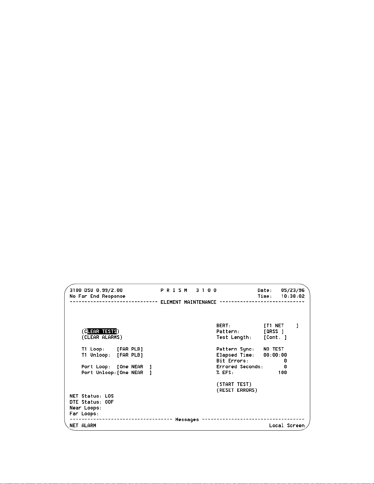
Element Maintenance
The Element Maintenance screen (Figure 3- 9) allows you
to perform loop test and/or BERT functions on the T1 circuit. You can activate and clear loops and the BERT tester.
BERT is performed by using on-board test facilities. No
other test equipment is needed. Some of these tests may also
be activated by the front panel push buttons as described in
Hardware Testing on page 4-1.
Clear Tests: Pressing <return> on this field clears all local
tests and any line loops that have been initiated.
Clear Alarms: Pressing <return> on this field causes all
near end alarms to be cleared.
T1 Loop: The type of T1 loop is chosen by toggling the
<spacebar> and is executed by pressing <return>. This unit
Configuration 3-6
Figure 3-9 Element Maintenance Screen
PRISM 3101/3102
Page 23

supports the following types of loops which are graphically
represented on pages 3-8 and 3-9.
Loop status changes can be made only when the
BERT function is not in the active mode.
NET PLB (Payload Loopback): The received network signal is looped back toward the network with signal regeneration and framing and CRC regeneration. During the NET
PLB, data from the DTE is looped back to the DTE. The
NET PLB may be activated by receipt of out of band loop
code on the network receive signal or by selection in the user
interface maintenance screen.
FAR PLB: You can activate a NET PLB on the remote end
unit through this selection.
NET LLB (Line Loopback): The received network signal is
looped back toward the network with signal regeneration
only (framing and CRC intact). During the NET LLB, data
from the DTE is looped back to the DTE. The NET LLB
may be activated by receipt of inband or out of band loop
code on the network receive signal, by the front panel loop
switch, or by selection in the interface maintenance screen.
FAR LLB: You can activate a NET LLB on the remote end
unit through this selection or through the front pan el TEST
switch (if configuration Switch S1-7 is set to Inba nd LLB).
NET MLB (Maintenance Loopback): The NET MLB command loops data at the T1 DTE port back toward the network (passes network data to the DTE and returns data to
the network). The MLB affects only network channels
assigned to the T1 DTE.
DTE MLB: The T1 DTE MLB command loops all network data back toward the DTE ports at the network interface. Data is passed through to the network. Set the T1NET Timing to Internal when this loop is enabled.
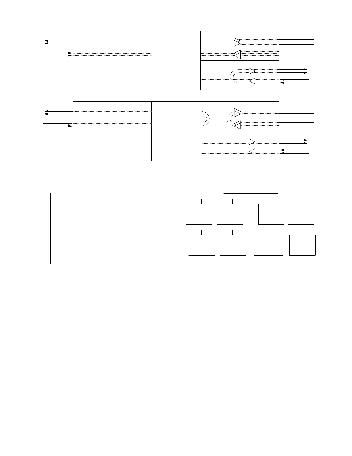
DTE LLB: The T1 DTE LLB command loops data
received at the T1 DTE interface back toward the T1 DTE
(al DS0s are returned to the T1 DTE port). The T1 DTE
data is also passed to the network.
Port Loop: T his field is used to loop high spe ed data port
from the network back to the network and data from the
DTE back to the DTE. The Port Loop may be activated by
receipt of inband V.54 fractional loop code or by this field.
On the PRISM 3102, each data port loops independently of
the other. The user activates a Port Loop on the remote end
unit through this field or by the front panel test switch. The
test switch can be used to activate a remote Port 1 loop if
configuration Switch S1-7 is set to Inband V.54. Either
method causes the unit to transmit inband V.54 fractional
loop code toward the network in the port’s bandwidth.
Port Unloop: Pressing <return> takes down the specified
loop from the currently selected port.
BERT: This field selects the interface and direction for the
test pattern transmission. The choices are: T1
NET, T1 DTE,
One NET, One DTE, Channel 1- 24, and IDLE. The 3102
includes the choices Two NET and Two DTE. The internal
BERT may also be activated through the front panel test
switch as specified under Hardware Testing on page 4-1.
Pattern: Specifies the pattern to be transmitted during a
test. Modifying this field will not
transmitted (refer to Start Test). The choices are [QRSS
[63], [511], [2047], [2
15
], [220], [223], [1:8], [3:24], [ALT],
cause the pattern to be
and [CLEAR].
Te st Le ng th : Defines the run -time of test pattern genera-
tion and error accumulation. The choices are [15 min], [30
min], [60 min], [24 Hour], and [Continuous
].
Start Test: Pressing <return> with the cursor on this field
starts the selected test pattern. TEST IN PROGRESS
appears once the test has started. To end the test, press
<return> on STOP TEST.
Reset Errors: Pressing <return> with the cursor on this
field causes the test error results to be cleared to zero.
The following fields are for display only. They reflect the
selected test parameters and the results of these tests only:
Pattern Sync: This field displays the current state of pattern sync during a test. If no test is in progress, NO TEST is
displayed. If a test is active, but the receiver is not in pattern
sync, NO SYNC is displayed. If the receiver is in pattern
sync, IN SYNC is displayed.
Elapsed Time: Displays the amount of time elapsed since a
timed test began or, if completed, the total test time.
Bit Errors: Displays the total number of bit errors detected
since the test began or since error statistics were cleared (Up
to a maximum number of 999,999).
Erro red Se cond s: This field dis plays the number of asynchronous errored seconds that have been detected since the
test began or since error statistics were last cleared. This
parameter includes bit error seconds and sync loss seconds.
% EFS: This ratio is derived from the number of error free
seconds divided by the number of seconds accumulated in
Elapsed Time.
L
INEFAULT ANDLOOPSTATUS
NET /DTE Status: These two fields display the fault status
of the network and the far end DTE. They indicate current
fault conditions. They do not indicate that alarm thresholds
are exceeded. Status indications are described in NET/DTE
Status: These two fields display the fault status of the network and the T1 DTE. They indicate current fault conditions. They do not indicate that alarm thresholds are
exceeded. Status indications are described in Table 3-I.
],
Configuration 3-7PRISM 3101/3102
Page 24

4
5
1
2
From Network
To Network
RJ48C
Network Interface
Framer/Deframer Multiplexor Receivers/Drivers
From
NET
To
NET
Framer/Defra mer
From
NET
To
NET
Receivers/Drivers
DTE (DSX1)
BERT Generator/
Detector
From
Ports
To
Ports
Normal Operation
(100' max.)
DTE (EIA 530 or V.35)
RJ48C
DSX1, 1'-655'
to cross-connect
1
2
4
5
4
5
1
2
From Network
4
5
1
2
From Network
4
5
1
2
From Network
4
5
1
2
To Network
RJ48C
To Network
RJ48C
To Network
RJ48C
To Network
RJ48C
From Network
Network Interface Framer/Defram er Multipl exor Receivers/Drive rs
From
NET
To
NET
NET
LLB
From
Ports
To
Ports
Receivers/DriversFramer/Deframer
BERT Generator/
Detector
From
NET
To
NET
DTE (DSX1)
Network LLB
Network Interface Framer/Defram er Multipl exor Receivers/Drive rs
From
NET
To
NET
From
NET
To
NET
Receivers/DriversFramer/Deframer
DTE (DSX1)
NET
PLB
All ones
to DTE
BERT Generator/
Detector
From
Ports
To
Ports
Network PLB
Network Interface Framer/Def ramer Multiplexor Receivers/Drivers
From
NET
To
NET
Framer/Deframer
From
NET
To
NET
Receivers/Drivers
DTE (DSX1)
BERT Generator/
Detector
From
Ports
To
Ports
Network MLB
Network Interface Framer/Defram er Multiplexor Receivers/Drivers
From
NET
To
NET
Framer/Deframer
From
NET
To
NET
Receivers/Drivers
DTE (DSX1)
DTE
MLB
BERT Generator/
Detector
From
Ports
To
Ports
DTE MLB
NET
MLB
(100' max.)
EIA 530 or V. 35
RJ48C
DSX1, 1'-655'
to cross-connect
(100' max.)
EIA 530 or V. 35
RJ48C
DSX1, 1'-655'
to cross-connect
(100' max.)
EIA 530 or V.35
RJ48C
DSX1, 1'-655'
to cross-connect
(100' max.)
EIA 530 or V.35
RJ48C
DSX1, 1'-655'
to cross-connect
1
2
4
5
1
2
4
5
1
2
4
5
1
2
4
5
Configuration 3-8
PRISM 3101/3102
Page 25
Port
Parameters
page 3-12
Alarm
Parameters
page 3-11
TCP/IP
Parameters
page 3-14
Configuration Menu
Management
Parameters
page 3-16
DBU
Parameters
page 3-13
Summary
page 3-17
SNMP
Parameters
page 3-15
Figure 3-10 Configuration Menu
Line
Parameters
page 3-10
4
5
1
2
From Network
4
5
1
2
From Network
To Network
RJ48C
To Network
RJ48C
Network Interface Framer/Deframer Multiplexor Receivers/Drivers
From
NET
To
NET
Framer/Defr amer
From
NET
To
NET
T1 DTE
LLB
Receivers/Drivers
DTE (DSX1)
BERT Generator /
Detector
From
Ports
To
Ports
DTE LLB
Network Interface Framer/Deframer Multiplexor Receivers/Drivers
To
NET
From
NET
Framer/Deframer
To
NET
From
NET
DTE
Near/Far
Receivers/Drivers
DTE (DSX1)
BERT Generator/
Detector
From
Ports
To
Ports
Port Loop (bidirectional)
(100' max.)
EIA 530 or V.35
RJ48C
DSX1, 1'-655'
to cross-connect
(100' max.)
EIA 530 or V.35
RJ48C
DSX1, 1'-655'
to cross-connect
1
2
4
5
1
2
4
5
Table 3-I Status Indications
Status Description
------- No status is available
OK No errors are currently detected.
ERR Frame bit errors, CRC errors, or BPVs are detected.
LOS A loss of signal condition exists.
OOF An out of frame condition exists.
RAI Far end is receiving a remote alarm indication signal.
AIS The far end is receiving an alarm indication signal.
UAS An unavailable signal state exists due to consecutive
severely errored seconds.
Near Loops: Displays the loop status of the near element.
Far Loops: Displays the loop status of the far element.
Configuration Screens
The Configuration screens allow you to view and set configuration parameters for the network elements.
To send a new configuration to the unit, you
must press <return> on one of the fields or exit
the screen. The underlined values are the factory
default parameter s.
Configuration 3-9PRISM 3101/3102
Page 26
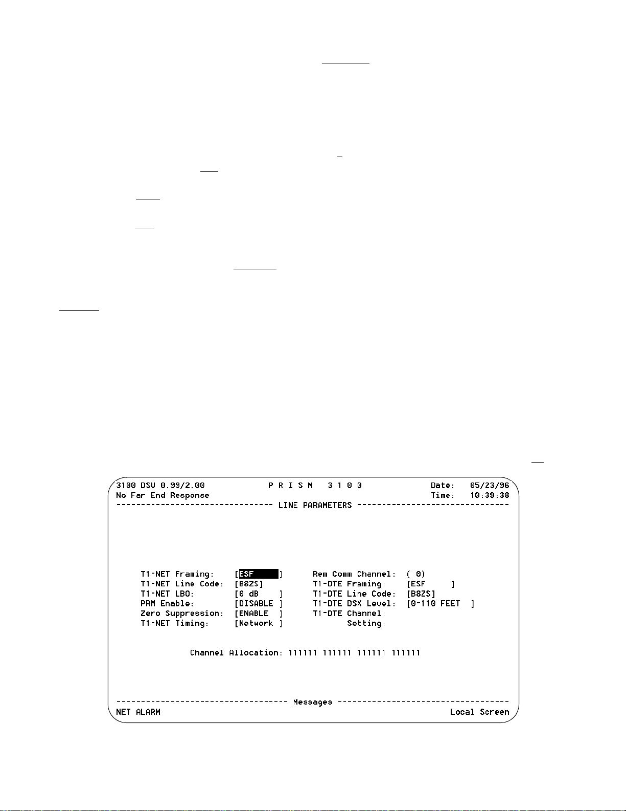
Line Parameters
The Line Parameters screen (Figure 3-11) allows you to
review and set line parameters for the selected element on
the T1 circuit. This screen has the following fields, most of
which have user selectable options. To send the new line
configuration to the unit, either press <return> on one of the
fields, change the Element selection, or exit the screen.
T1 -NET Framing: Selects the type of framing for the network side of the element as either [ESF
T1 -NET Line Code: Sets the networ k side line coding as
either [AMI] and [B8ZS
T1-NET LBO: Sets the line build out for the network
interface as either [0
PRM Enable: This field allows the T1.403 Performance
Report Message, which is sent once a second, to be turned
on or off. The choices are [ENABLE] and [DISABLE
Zero Suppression: This field determines whether ones
density insertion is activated after 15 zeros. The choices are
[ENABLE
T1-NET Timing: Sets the timing source to synchronize
the unit’s internal timing generators. Slips are controlled to
occur on frame boundaries at the network and/or DSX1
ports when timing synchronization is lost.
INTERNAL: The unit’s internal frequency standard is used
for all timing.
PORT 1: Timing is synchronized to the external terminal
timing clock supplied from the DTE and connected to the
selected port.
] and [DISABLE].
Verify that the external DTE clock is operating at
the data rate selected for Port 1.
].
dB], [-7.5 dB], [-15 dB], or [-22.5 dB].
] and [D4].
].
NETWORK
clock (most applications use this selection).
T1-DTE:The unit synchronizes the clock recovered from the
DSX-1 T1 DTE port.
Remote Comm Channel: This field selects a communica-
tion link to the far end unit. You can either assign a DS0
channel (1 through 24) or use an ESF facility data link (0).
If ‘0
ESF facility data link (valid only when the network interface is configured for ESF and the FDL has end-to-end
integrity). For example, the entire T1 bandwidth must be
available to the user with no intervening mul tiplexors in the
signal path blocking the FDL.
As an alternative, the communication link may be assigned
to an unused idle channel. This option may be used whether
the network is operating in D4 or ESF modes.
When the remote communication is programmed to operate
over a spare network channel, test conditions such as a
remote network LLB or PLB or a local network LLB will
interrupt access to the far end unit.
When the remote communication is programmed to operate
over the facility data link (FDL), test conditions su ch as a
remote network LLB or a local LLB on the near end will
interrupt access to the far end unit.
T1-DTE Framing: Selects the type of framing for the T1DTE side of the element. The unit will support ESF to SF
or SF to ESF conversions. The choices are ESF or D4
: Timing is derived from the network recovered
’ is selected, communication is established over the
If far end communication is in terrupted for any
reason while accessing the remote unit, you
should exit and then reenter this screen to ensure
that all the parameters have been updated.
.
Configuration 3-10
Figure 3-11 Line Parameters Screen
PRISM 3101/3102
Page 27

T1-DTE Line Code: Sets the network side line coding as
either AMI
or B8ZS.
T1-DTE DSX Level: Specifies the DTE line build-out signal level as either 0-110 ft
, 111-220 ft, 221-330 ft, 331-440
ft, 441-550 ft, 551-660 ft, or >660 ft.
T1-DTE Channel: Selects channels to be assigned to the
T1/DTE from 1 through 24.
Settings:Selects the channel to be either IDLE or THRU.
Channel Allocation: This disp lay- only field indicates the
network channel assi gnme nts wit h Channe l 1 on the le ft and
Channel 24 on the right. Channels assigned to a port are
identified with a port number (1 or 2). Non-assigned idle
channels are marked with a dash (-). Remote communication channels are marked with an R. T1-DTE channels are
marked with a D.
A
LARMCONFIGURATION
The Alarm Configuration screen (Figure 3 -12) allows you
to review and set alarm related thresholds for the selected
element. These thresholds are the minimum acceptable performance levels. To modify the parameters, highlight the
desired statistic, type in the new value (any number from 0
to 900) and press <return>. If this value is later surpassed,
an alarm indication will appear. A field set to (0) will cause
the element not to alarm on that statistic.
Errored Seconds: A one second period in which at least
one logic error occurred.
Severely Er rored Secon ds: A one second period in which
at least 320 CRC errors or 1 OOF (out-of-frame) occurred.
Loss of Signal Seconds: A one sec ond perio d in which the
T1 received signal is interrupted.
Unavailable Seconds: A one second period in which consecutive severely errored seconds cause an unav ailable state.
Remote Alarm Seconds: Generated by the terminal equipment when an improper signal is received from the facility
(or upon receipt of unframed all ones).
AIS Seconds: One second period when all ones are received.
Out of Frame Seconds: A one second period in which a
frame sync loss occurred.
BPV Seconds: A one second period in which at least one
bipolar violation occurred.
DTE LOS/OOF Seconds: A one second period where the
T1-DTE received signal frame synchronization is interrupted or the amplitude drops below a certain level.
Alarm Reset Timer: Determines the number of seconds
after alarm conditions clear before indications are removed.
Figure 3-12 Alarm Configuration Screen
Configuration 3-11PRISM 3101/3102
Page 28

P
ORTCONFIGURATION
The Port Configuration screen (Figure 3-13) sets the operating parameters for each high speed port. The unit does not
allow conflicting configurations for the DTE ports. Therefore, the selections for each menu item are restricted to
those that do not conflict with the configuration of the other
high speed port. The default is all channels disabled
.
When channel assignment changes are made to the high
speed ports or to the remote communi cation link, the 3101/
3102 reestablishes the mapping o f all channels. This interruption to traffic will normally result in a brief burst of data
errors on other ports.
Channel Allocation: This display -only field indicates the
network channel assignments with Chan nel 1 on the left and
Channel 24 on the right. Channels assigned to a port are
identified with a port number (1 or 2). Non-assigned idle
channels are marked with a dash ( -). Remote communication channels are marked with an ‘R’. When channels are
assigned to a port in the ALTERNATE assignment mode,
each data channel is followed by an idle channel that is not
assignable for other ports and is marked with an X. T1-DTE
channels are shown with a D.
Port #: Selects the port to be configured, such as [ONE] or
[TWO].
Rate Multiplier: The unit can operate at any data rate that
is a multiple of 56 or 64 kbps. When Nx64K is selected, the
ones density requirements of the T1 network line must be
ensured. When N x 56K
is selected, the unit maintains ones
density for the selected DS0 channel.
DS0 Channel Assignment: Selects whether the DTE chan-
nel assignment will be made as a CONTIGUOUS
group or
as ALTERNATE channels. Selecting ALTERNATE will
assure ones density but reduce the available bandwidth from
1.536 kbps to 768 kbps.
Start Channel #: The starting channel in the 24 -channel
DS1 bit stream must be selected in this field. The unit then
assigns the following channels automatically according to
the bit rate multiplier and the mode selected in DS0 Chan nel
Assignment. The choices are 1 through 24.
Port Rate : Pressing the <spacebar> increases the required
port bit rate in increments of 56 or 64 kbps, depending on
the Rate Multiplier setting. The N multiplier ranges in value
from 0 to 24.
# of Channels: This field displays the number of channels
to be passed through to the DTE. The number is determined
by the Port Rate value divided by the Rate Multiplier.
Tr an s mi t C l oc k : This field is used to select the clock that
the unit will use to sample the data transmitted from the
DTE. When set to INTERNAL
, the data is automatically
edge-aligned and sampled directly with the transmit data
clock that is also supplied to the DTE as Transmit Clock.
The EXTERNAL option uses the external clock supplied by
DTE. The OVERSAMPLE option is used to operate the port
as a low speed asynchronous port. In this mode, the port rate
should be set to at least 4 times the asynchronous data rate
(depending on the degree of allowable distortion for the particular DTE equipment used).
LL (Local Lo op) Detect: Allows you to enable or disable
pin J (V.35) or pin 18 (EIA 530) to loop-up the near (local)
unit.
Configuration 3-12
Figure 3-13 Port Configuration Screen
PRISM 3101/3102
Page 29
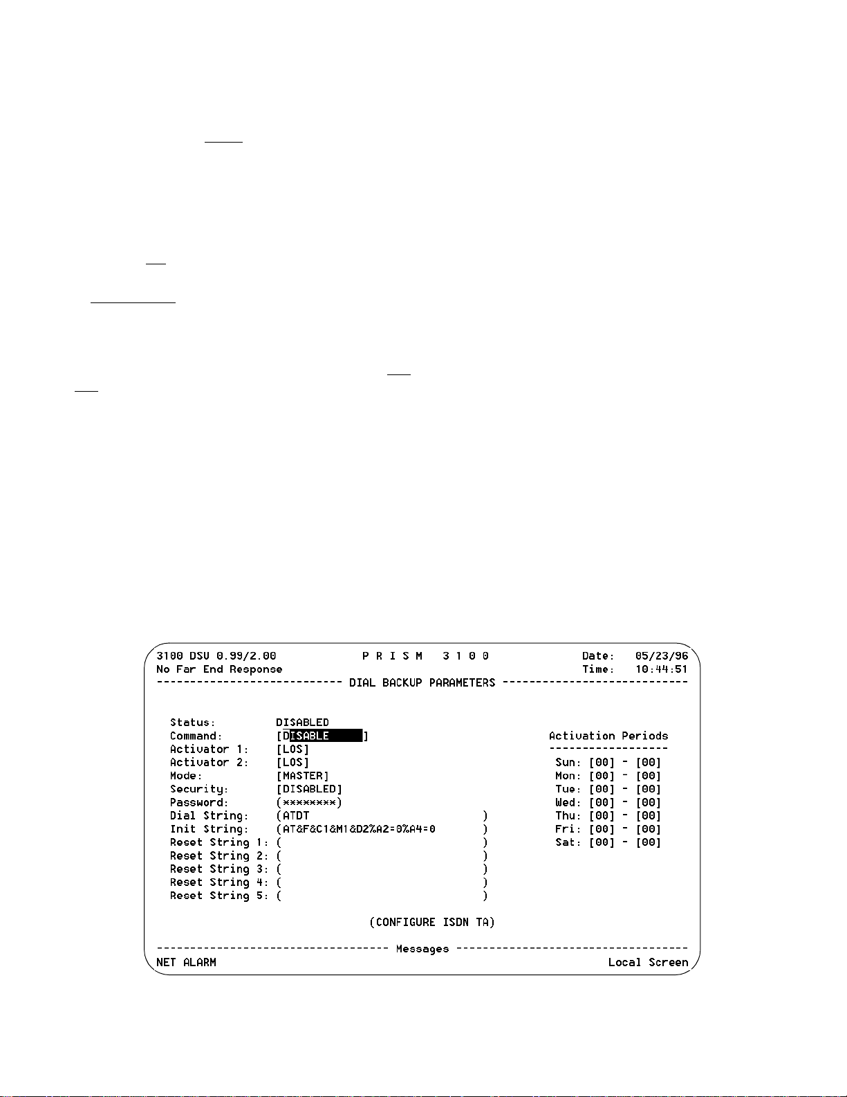
RL (Remote Loop) Detect: Allows you to enable or disable the monitoring of pin BB (V.35) or pin 21 (EIA 530) to
loop-up the far unit.
V.54 Loop: Selecting Enable
allows the unit to respond to
inband V.54 loop commands. If you select Disable, the unit
ignores these commands.
Invert Data: In the invert mode (YES), transmit and
receive data are inverted at the port interface. This function
may be used as a means of guaranteeing ones density when
the data is composed of SDLC type protocols. The choices
are YEs and NO
.
CTS /DSR/ DCD Control: Setting any of these three fields
to FORCE TRUE
or FORCE FALSE allows the forcing of
the port control lead output state. INTERNAL allows for
normal operation.
Alarm on DTR Loss: Selecting [Enable] allows the unit to
go into alarm on loss of DTR. The default setting is [Disable].
D
IAL BACKUP PARAMETERS
The Dial Backup Parameters screen (Figure 3- 14) allows
you to configure the DBU port. You can enable the DBU
functionality by selecting two of the eight available alarm
indicators or by selecting ANY. These parameters can be
any one of nine errors (LOS, ES, SES, UAS, LOF, RAS,
AIS, BPV, ANY). These parameters allow you to establish
pre-defined thresholds (set in the Alarm Parameters screen)
and initiate dial backup when these thresholds are exceeded.
See Alarm Configuration on page 3-11 to set
the threshold parameters.
Alarm Reset Timer: This field can be set for zero to 900
seconds. If you set this field to zero, when you enter into
dial backup you will stay in that mode even if the T-1 circuit
is re-established. If you set this field from 1-900, the circuit
will be up that period before it re-establishes.
See Alarm Configuration on page 3-11 to set
the thresholds for this field.
Status: Lists the current DBU status as either Disabled,
Enabled, Active, Locked, Connecting, Disallowed, Dialing,
or Disconnecting.
Command: Disable, Enable, Enable Daily, Activate, or
Lock.
Activator 1: Allows you to set the first threshold value for
initiating a dial backup. Available values are LOS, ES, SES,
UAS, LOF, RAS, AIS, BPV, ANY.
Activator 2: Allows you to set the second threshold value
for initiating a dial backup. Available values are LOS, ES,
SES, UAS, LOF, RAS, AIS, BPV, ANY.
Mode: One unit must be configured as a master unit and
one unit must be configured as a slave. This determines priorities when both units try to establish a DBU connection.
Security: Allows you to enable or disable the security
function limiting access to the DBU interface. The security
setting must be the same on bo th ends.
Password: If the security feature is enabled, the password
for the security option must be the same on both devices.
Dial String: Character string used to dial the other unit.
Init String:Character string used to configure the modem to
dial the other unit.
Figure 3-14 Dial Backup Parameters Screen
Configuration 3-13PRISM 3101/3102
Page 30
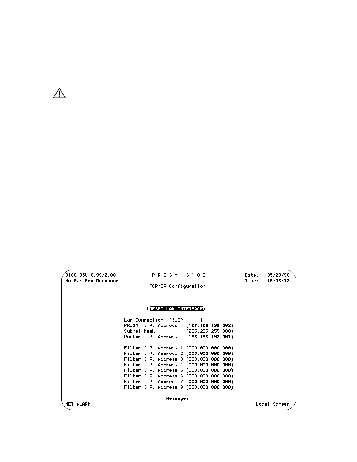
Reset String:These strings (1-5) are used to reconfigure the
ISDN TA when the unit has trouble making a connection.
Configure ISDN TA: Routes you to the user interface of
the switched service DBU unit. This feature allows for the
configuration of necessary parameters in the switched unit.
Activation Periods: Period of time when the unit is
allowed to enter an active DBU state.
When configuring activation periods in the Time of Day map, be sure
to calculate any time zone differences.
Reset LAN Interface: For changes to take effect, the LAN
interface must be reset or the unit must be power cycled.
Selecting this field brings up a confirmation screen which
prompts you to proceed with the reset.
TCP/IP C
ONFIGURATION
The TCP / IP Configuration screen (Figure 3- 15) is accessible for the SLIP, Ethernet or Token Ring SNMP interface. It
allows for the entry of those parameters required for p roper
operation with an Ethernet or Token Ring-based LAN manager.
LAN Connection: This field allows you to select S
LIP
Ethernet, or Token Ring interface for the network connection.
PRISM I P Address: This field accepts IP addresses. Each
device connected to the LAN is required to have a unique IP
address identifier.
Subnet Mask: T his field is provided to m anually override
the subnet mask setting which is otherwise discovered by
the SNMP agent.
Router IP Address: This field accepts the IP address of the
default router.
Filter IP Address: These eight fields accept the IP address
of the source packet filter. If any of these fields are set,
access is allowed only by the specified IP addresses.
,
Configuration 3-14
Figure 3-15 TCP/IP Configuration Screen
PRISM 3101/3102
Page 31
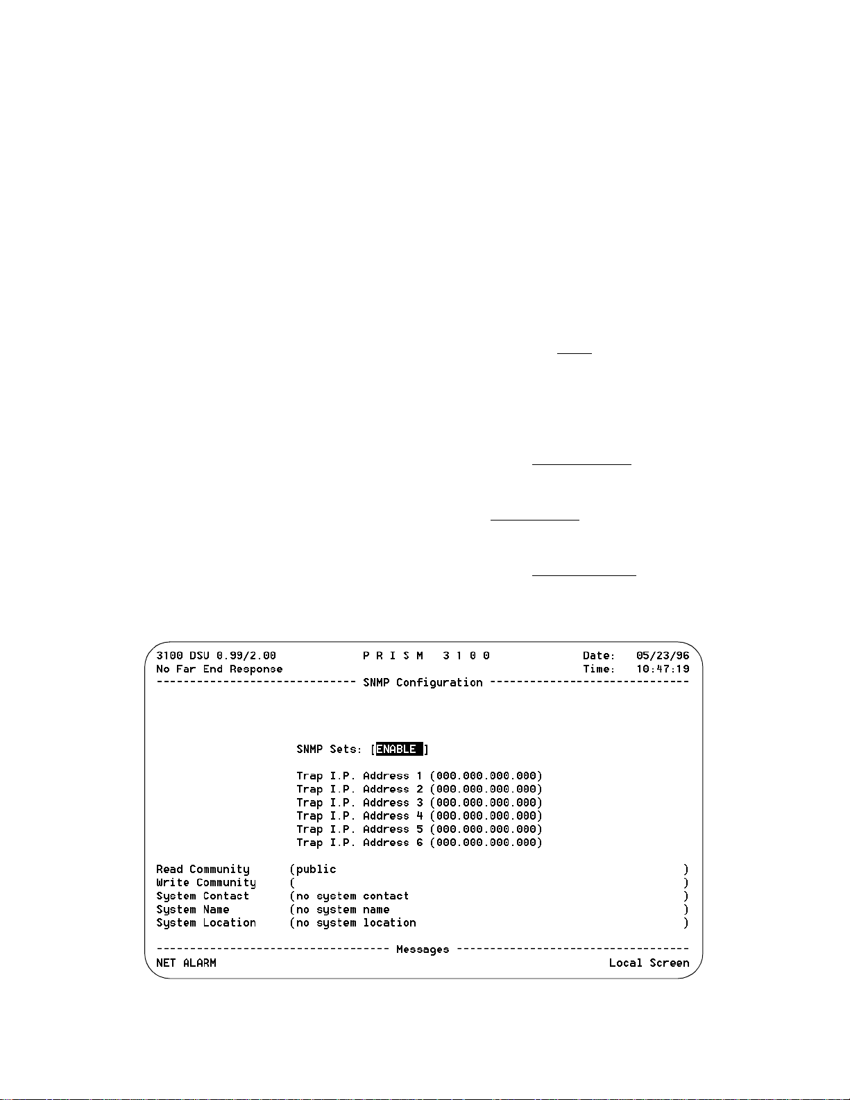
SNMP C
ONFIGURATION
The SNMP Configuration screen (Figure 3-16) is accessible
for the SLIP, Ethernet or Token Ring SNMP interface. It
allows for the entry of those parameters required for proper
operation with an SNMP-based network manager.
The 3101/3102 supports alarm reporting by SNMP TRAPs
when running the LAN or SLIP interface. If the unit’s IP
Connection is LAN or Direct SLIP, it expects an IP connection to always be present and thus outputs its TRAP messages immediately. If the IP Connection is Dial SLIP, the
unit dials out from the modem connected to the SLIP port
using the number programme d in the SNMP Configuration
screen an outputs TRAP messages upon connection.
The PRISM 3101/3102 has an embedded SNMP agent supporting MIB-2 and the DS1/E1 MIB. The SET command is
supported and has the functionality described below. The
3101/3102 also supports a single TELNET session.
SNMP Sets: This field enables or disables the set command responses for SNMP. Refer to Appendix C,
SNMP Agent for detailed information on these responses.
TRAP IP Address: These six rows require numeric
entries. Each row contains four 3- digit numbers which are
separated by periods. Each of these numbers can range from
0 to 255.
These fields accept the IP address of a network device to
which alarm reporting TRAPs are to be sent. The unit
detects and reports alarms and provides several options for
reporting them, one of which is SNMP TRAPs. When an
alarm occurs, the unit sends a trap message to up to 6 destinations on the user’s network. The trap message is formatted
per RFC 1157. The generic trap type is enterpriseSpecific
(generic-trap = 6).
Up to 6 Trap IP addresses can be assigned to report via
SNMP. The unit will report each alarm by transmitting an
SNMP Trap to each Trap IP address. T1 network problems
often cause more than one alarm type. In these cases, multiple trap messages are generated, each with a different specific trap type. The specific -trap field of each trap message
is set to one of th e values shown in th e Trap Definition table
on the previous page.
The following five menu items allow the entry of up to 58
characters identifying the appropriate group, person, device
function, or unit location.
Read Community: This display accepts a character string
identifying the group authorized to perform read operations.
The default setting is public
.
Write Community: This display accepts a character string
identifying the group authorized to perform write operations. The default setting is a null s tring (‘ ‘).
System Contact: This display accepts a character string
identifying the person responsible for a network device. The
default setting is no
system contact.
System Name: This display accepts a character string identifying the functionality of the network device. The default
setting is no
system name.
System Location: This display accepts a character string
identifying the physical location of network device. The
default setting is no
system location.
Figure 3-16 SNMP Configuration Screen
Configuration 3-15PRISM 3101/3102
Page 32

M
ANAGEMENTPORTS
The Management Ports screen (Figure 3-17) sets the following parameters for the Call On Alarm (COA) connection
on both the SUPV and SLIP ports.
Element ID: This field allows the entry of an ASCII string
(29 characters in length) which identifies the unit to the
device receiving the alarm notification messages.
Call on alarm messages are reported in the following format
in the [DIAL] or [DIRECT] modes only:
Element ID HH:MM:SS MM/DD/YY <CR> <LF>
NET Alarms: alarms <CR> <LF>
DTE Alarms: alarms <CR> <LF>
where (alarms) is a string consisting of some or all of the
identifiers LOS, OOF, RAS, AIS, UAS, ERRS, or NONE.
The following is an example:
Joesunit 17:24:55 08/04/93
NET Alarms: LOS AIS ERRS
DTE Alarms: LOS Port1
The user programmable Element ID string is transmitted
first to allow the COA function to send a message with a
specific meaning to some host (such as a log on message).
The identifier
ERRS
represents an alarm that is
caused by ES, SES, and/or BPV errors.
COA Connection (SUPV): This field controls the remote
alarm reporting. ASCII alarm reporting through the supervisory port is independent of TRAP alarm reporting. The
ASCII alarm report type is set by the following choices:
[DISABLED
] - Alarm reporting is disabled.
[DIAL] - Sends reports through an attached AT command
set compatible modem connected to the SUPV serial port,
which must dial out to a remote modem. The message format is described in the Element ID field.
[DIRECT] - Sends reports to a printer or terminal connected
directly to the supervisory port.
Primary Dial String, Secondary Dial String:These fields
are ASCII strings for the primary and secondary call on
alarm phone numbers used in the [DIAL] mode. The strings
must NOT include the ATDT command prefix.
The unit attempts 3 times to connect u sing the primary number. If all 3 attempts fail, it will attempt 3 times to co nnect
using the secondary number (if it is not blank). If the secondary number fails, the unit waits 5 minutes and then
attempts to communicate with the primary number again.
When a connection is detected, the unit outputs the notification message (as described in the Element ID field) and then
disconnects.
Initialization String: The modem initialization string is
entered in this field. Refer to the modem’s documentation
for further information. The default setting is
ATEQ0V1
.
Disconnect String: This field identifies the character string
to be output when the modem session is terminated. The
default setting is
ATH
.
COA Connection (SLIP): This field controls remote alarm
reporting. ASCII alarm reporting through the SLIP port is
independent of TRAP alarm reporting. The ASCII alarm
report type is set by the following choices:
[DISABLED] - Alarm reporting is disabled.
[DIAL] - Sends reports through a modem to the SLIP
server.
Configuration 3-16
Figure 3-17 Management Ports Screen
PRISM 3101/3102
Page 33

[DIRECT
Compressed SLIP: The choices are AUTO
DISABLE. The AUTO
negotiate with the far end to enable or disable SLIP compression, depending on the type of conn ection.
S
UMMARY
The Summary screen (Figure 3-18) is a displa y- on ly screen
which summarizes all the configuration switch settings in
] - Sends reports directly to the SLIP server.
, ENABLE, and
setting allows the 3101/3102 to
the left column. Other pertinent information is shown in the
right column.
Utilities
The Utilities screen (Figure 4-23) handles the functions
described in the following paragraphs.
Set Time: The current time may be entered in this field
using the 24- hour HH: MM: SS format. For example, 3:45
AM is entered as 0345 and 3:45 PM is entered as 1545.
Figure 3-18 Summary Screen
Figure 3-19 Utilities Screen
Configuration 3-17PRISM 3101/3102
Page 34

Set Date: The current date may be entered in this field
using the MM :DD:YY format. For example, July 4, 1993 is
entered as 070493.
The time and date can b e set at the far end, but
not displayed.
New Password: This field allows entry of a password of up
to 10 characters. An empty string (carriage return only) may
be entered to disable the password feature. After <return> is
pressed, the new password is activated and is no longer visible. Therefore, type carefully when entering a new password and verify before pressing <return>. When the
terminal interface is exited and later reactivated, this password must be entered exactly to gain access. If the wrong
password is entered, the following message will appear:
Incorrect Password; Please Enter Again.
Do not exit the terminal interface
program until the password procedure is fully understood. If a password
has been specified, it must be typed
exactly to reenter the program.
If you program a password and later forget it, contact
TxPORT Technical support for a one-time backdoor password.
The reset operation sets all parameters to the
factory default settings and zeros all performance registers.
Maintenance Reset: This field will clear all user select able
parameters, performance registers, passwords, and alarms
but saves the IP Address. All alarm threshold parameters
will be reset to default values. The unit reload s start-up con figuration settings from the default parameters stored in
ROM. Pressing <return> on this field brings up the following warning:
DELETE ALL DATA AND RESTART UNIT?
(NO!) (YES)
Factory Reset: Removes all memory including the IP
Address.
To exit this screen without performing the reset function,
press <return>with NO selected. To proceed with the reset
function, move the cursor to YES and press <return>.
SNMP / TELNET
Any workstation emulating an ANSI VT100 terminal can
communicate with the 3101/3102. Note that only a single
TELNET session is supported at any one time.
You must be familiar with TELNET operation to begin
communication with the unit (refer to the TELNET documentation) The TELNET interface provides security
through password layers identical to thos e described in this
chapter for the terminal interface. Once communication is
established, all TELNET screens are identical to those
described for the terminal interface.
Configuration 3-18
PRISM 3101/3102
Page 35

4. Testing
TRANSPORT
®
This chapter describes hardware and software testing procedures and responses for the PRISM 3101/3102.
Hardware Testing
The PRISM 3101/3102 front panel (Figure 4-1) has five
LED indicators and two control buttons from which you can
perform basic unit testing.
Front Panel LEDs
Five front panel LEDs allow a visual identification of the
test results and alarms. These LEDs are: NET, BACKUP,
TEST, ALARM, and POWER.
NET
This LED is green when the unit is in frame sync. It is
amber when the unit is receiving a yellow alarm from far
end. It is red when the unit is out of frame sync and/or Loss
of Signal.
BACKUP
Amber LED blinks when dialing, connecting, or disconnecting. Solid illumination when active.
TEST
This LED flashes green when the unit is transmitting loop
code. It is green continuously when BERT is on with no
errors OR the unit is in clear test. It is red when the BERT is
on and is receiving errors.
ALARM
Red LED lights continuously when the unit is in an active
alarm condition. It flashes when an invalid switch configuration has been made .
POWER
Green LED lights continuously when power is applied to the
unit.
Front Panel Buttons
Two front panel buttons allow you to perform loopback
tests. The two buttons are: TEST and LOOP.
TEST
When this button is pushed once, the unit transm its five seconds of in-band loop code out to the network either LLB or
V.54 depending on the setting of configuration Switch S2- 7
(page 3 -2). The indicator blinks green during transmission
of the loop code.
If configuration Switch S2-8 (page 3-2) is set to Clear
Loop, a bidirectional loop is created allowing the central
office to initiate a BERT.
If Switch S2 - 8 is set to BERT, the test pattern last selected
in the terminal interface is transmitted toward the network.
The received pattern is compared and if the pattern is
received error free, the TEST indicator remains green. If
pattern errors are detected, the TEST indicator turns red for
one second for each errored second. Therefore, if five
errored seconds are received, the indicator will remain red
for five seconds. The data ports are looped back toward the
DTE during the test.
If the TEST button is pushed again, th e unit transmits five
seconds of in-band loop down code and returns to normal
operating mode. The TEST indicator is then turned off.
LOOP
When this momentary push button is pushed once, the unit
activates a line loopback, looping the network receive data
back to the network, and looping the data from the DTE
ports back to the DTE. The TEST indicator is illuminated
while the unit is in loop. If pushed again, the unit clears the
loop and turns off the LOOP indicator.
For additional information concerning test and
loop options, refer to the section Software Configuration on page 3-3.
Software Testing
When indepth testing is necessary, you can perform specific
tests from the VT100 interface into the PRISM 3101/3102
menu system.
PRISM 3100 Series
TEST LOOP
Figure 4-1 Front Panel Controls and Indicators
ALARMTESTBACKUPNET
POWER
Testing 4-1PRISM 3101/3102
Page 36

Testing 4-2
PRISM 3101/3102
Page 37
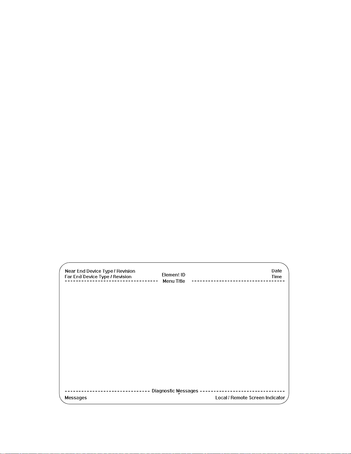
A.Terminal Interface
This chapter describes the screens structure and menu controls for the TxPORT PRISM 3101/ 3 102 t erminal interface.
The interface is a firmware application program embedded
inside the unit.
It requires an ANSI compatible VT100 terminal (ASCII), or
a computer running an ANSI terminal emulation program.
The terminal interface uses ASCII BREAK and ESCAPE
functions, which are implemented differently with the various terminal emulation programs.
Screen Components
Terminal interface screens have several components common to all screens (Figure A-1).
Device Type and Revision: The device type (such as
PRISM 3102) and the revision control numbers are shown
in the upper left corner. The first number is the hardware
revision and the second number is the software revision.
Information is displayed for the near end unit (connected
directly to the terminal) on the top line, and for the far end
unit (connected to the network T1 interface) on the second
line. Refer to this information when contacting the factory
with inquiries.
The far end information is available only for TxPORT products that support a proprietary message set. If the far end
does not support these messages but does support the standard 54016 protocol, then the far end information is displayed as GENERIC 54016 FAR END. If the far end does
not respond to either proprietary or 54016 messages, then
NO FAR END RESPONSE will be displayed. If the far end
echoes the FDL messages transmitted by the near end unit,
then FAR END LINE LOOP is displayed.
Date/Time: The top right corner of the terminal screen displays the current date and time. The setting of these functions
is described in the section entitled Utilities on page 3-17.
Element ID: Below the header (PRISM 3100), the Element
ID is displayed. Refer to the section entitled
Management Ports on page 3-16 for information on the
Element ID.
Menu Title: The men u title (third line, center) denotes the
general classification of functions currently accessible by
the user (such as MAIN or PERFORMANCE).
Messages: Diagnostic messages may be displayed at the
bottom of the screen.
Local / Remote Screen Indicator: Identifies the visible
screen as displaying the local or remote interface.
Cursor Controls
The terminal interface utilizes a highlighted cursor to make
selections from menus and select fields within screens to be
operated on. The cursor is moved in different ways, depending on the terminal emulation program used. Most programs
allow use of the <tab> and <shift -tab> keys. Others allow
use of the arrow keys. Once a field is highlighted, it is
manipulated as described in Section .
Figure A-1 Terminal Interface Layout
Treminal Interface A-1PRISM 3101/3102
Page 38

For keyboards which do not have these standard keys or
Alarms
MAIN
MENU
Log
Off
LogOnPerformance
Maintenance
Configuration
Utilities
Standard 24-Hour
Enhanced 24-Hou r
Standard 30-Day
Enhanced 30-Day
Line Parameters
Alarm Parame ters
Port Parameters
TCP/IP Parameters
SNMP Parameters
Management Ports
Summary
DBU Parameters
Figure A-2 Terminal Interface Menu Structure
have only some of them, an alternate set of cursor control
commands is provided. Each command is performed by
pressing a letter key while holding down the <Ctrl> key.
Alternate commands may be freely mixed with the keyboard commands at your discretion.
Table A-A Keyboard / Alternate Commands
Keyboard Command Alternate Command
< left arrow > < Ctrl - S >
< right arrow > < Ctrl - D >
< up arrow > < Ctrl - E >
< down arrow > < Ctrl - X >
< backspace > < Ctrl - H >
< delete > < Ctrl - Z >
Field Types
Each screen is made up of fields. The two basic field types
are user-selectable and display-only. If the highlighted cursor can be moved to a field, it is a user selectable field. All
other fields are for display only. User selectable fields allow
for changes to be made or commands to be executed.
Fields without brackets or parenthesis are display-only.
They cannot be changed on the screen. Most user selectable
fields are enclosed in brackets or parenthesis and are
described in the following paragraphs.
Fields enclosed in brackets [ ] offer the user a list of selections from which to choose. The selections may be toggled
by pressing the <spacebar>. Each time it is pressed, a new
item appears. When the appropriate choice is displayed,
press <return> to select it.
Fields enclosed in parenthesis ( ) are manipulated by one
of the following two methods:
1. Pressing <return> on such fields as (Reset) and (Start
T est) simply exec ute the function.
Any screen may be redisplayed (or refreshed) by
pressing <Ctrl - U>. Any changes to fields on a
screen, that have not been activated by pressing
<return>, will be discarded.
Menu Structure
The Main Menu screen lists the functional user accessible
menus. To activate a menu, highlight the desired selection
and press <return>. To exit this or any subsequent menu,
press <esc>. If the Main Menu is exited, the terminal interface program terminates. This is a valid way to end a session. If any other menu is exited, the previous screen is
returned. The menu structure (Figure A-2) shows all the
screens accessible from the Main Menu.
If you do not ent er a keystroke for
10 minutes, the terminal interface
logs off automatically.
2. The most common type of field in parenthesis accepts
typed input in the form of letters and / or numbers. Typing characters when the field is highlighted causes the
current entry to be replaced with the new characters. To
edit an existing entry rather than replace it, press the
<right arrow> key to move the cursor to the point that
needs editing. Characters may then be inserted or
deleted. Typed data is always inserted rather than typed
over. If the field is full, though, at least one character
must be deleted to add another.
Many fields of this type may also be toggled by pressing the
<spacebar>. Other fields are range checked, where the user
is not allowed to exit with an illegal value set.
Terminal Interface A-2
PRISM 3101/3102
Page 39

B.Pinout Tables
This appendix displays the pinout assignments for each port
and option on the rear of the PRISM 3101/3102
LAN Port - Ethernet
Pin Signal Name
1 Data Out
2 Data Out
3 Data In
6 Data In
LAN Port - Token Ri ng
Pin Signal Name
3 Data Out
4 Data In
5 Data In
6 Data Out
SLIP / SUPV Port - PC
Pin Signal Name DTE
1 DCD Out DCD
2CTS Out CTS
3 Frame Gnd Frame Gnd
4 Data Out RXD
5 Data In TXD
6 Signal Gnd Signal Gnd
7 RTS In RTS
8 DTR In DTR
SLIP / SUPV Port - Modem
Pin Signal Name DCE
1 DTR Out DTR
2 RTS Out RTS
3 Frame Gnd Frame Gnd
4Data Out TXD
5 Data In RXD
6 Signal Gnd Signal Gnd
7 CTS In CRTS
8 DCD In DCD
T1 DTE Port
Pin Signal Name
1 Data Out
2 Data Out
3,6 Not Used
4 Data In
5 Data In
7 Chassis Ground
8 Chassis Ground
NET P ort
Pin Signal Name
1 Data In
2 Data In
3,6 Not Used
4 Data Out
5 Data Out
7,8 Chassis Ground
DBU Port
Pin Signal Name
1 Rx Clock In
2 DTR Clock Out
3 RTS Clock Out
4 Frame Ground
5Data Out
6Data In
7 Signal Ground
8CTS In
9 DCD In
10 Tx Clock In
Pinout Tables B-1PRISM 3101/3102
Page 40

Data Ports
Signal Name EIA 530 V.35 Acronym
Frame Ground 1 A FG
Transmit Data 2, 14 P, S TD
Receive Data 3, 16 R, T R D
Request to Send 4, 19 C RTS
Clear to Send 5, 13 D CTS
Data Set Ready 6, 22 E DSR
Signal Ground 7 B SG
Data Carrier Detect 8, 10 F DCD
Transmit Cloc k 15, 12 Y, AA TXC
Receive Clock 17, 9 V, X RXC
Local Loopback 18 J LL
Data Term Ready 20, 23 H DTR
Remote Loopback 21 BB R L
Terminal Timing 24, 11 U, W TT, EXC
Pinout Tables B-2
PRISM 3101/3102
Page 41

C.SNMP Agent
This unit has an embedded SNMP agent which can be
accessed either through the built in SLIP interface or the
optional Network Interface Card (NIC). The NIC can either
be an Ethernet or Token Ring interface. Through these interfaces the user can gain access to the 3100 via Telnet or
SNMP. The Telnet session is simply a connection to the user
interface of the unit.
SNMP access to the unit is limited to Management Information Bases (MIBs) supported by the embedded SNMP agent.
The SNMP agent supports MIB-II (RFC 1213) and the latest DS1 MIB (RFC 1406). This appendix describes in detail
how the embedded SNMP agent conforms to the RFCs.
RFC 1213
This RFC defines the MIB-II specification.
systemTable
sysDescr: (read-only)
GET: returns the string ‘TxPORT SNMP Agent’
sysObjectID: (read-only)
GET: returns the Object Identifier - 1.3.6.1.4.1. 254.1.1
sysUpTime: (read-only)
GET: returns the time in hundredths of a second since the net-
work interface was reset.
sysContact: (read-write)
GET: returns the System Contact string for the unit,
defaults to ‘no system contact’
SET: sets the System Contact string for the unit
sysName: (read-write)
GET: returns the System Name string for the unit,
defaults to ‘no system name’
SET: sets the System Name string for the unit
sysLocation: (read-write)
GET: returns the System Location string for the unit,
defaults to ‘no system location’
SET: sets the System Location string for the unit
sysServices: (read-only)
GET: returns a value of ‘72’ which represents a host offering
application services.
ifTable
ifNumber: (read-only)
GET: returns the number of interfaces present on the unit, there
are always a minimum of 3 (SLIP, Network - DS1, and
Port 1). There are two option al interfaces, a NIC (Ethernet
or Token Ring), and a Port 2 card.
ifIndex: (read-only)
GET: returns value of the specified interface, ordered as fol-
lows:
1
- SLIP
2
- NIC (if installed)
3
- DS1
4
- D/I (if installed)
5
- Port 1
6
- Port 2 (if installed)
7
- Dial Backup
ifDescr: (read-only)
GET: returns one of the following textual descriptions:
‘SLIP Interface’
‘Ethernet NIC’
face
‘Token Rin g NIC ’
‘T1 Network Interface’
‘T1 DTE Interface’
face (D/I)
‘V.35 Data Port 1’
face)
‘V.35 Data Port 2’
face)
‘530 Data Port 1’
‘530 Data Port 2’
‘DBU Interface’
- returned for the SLIP Interface
- returned for the NIC, for Ethernet inter-
- returned for the NIC, for Token Ring
- returned for the DS1 interface
- returned for the T1 DSX-1 inter-
- returned for Port 1 (if a V.35 inter-
- returned for Port 2 (if a V.35 inter-
- returned for Port 1 (if a 530 interface)
- returned for Port 2 (if a 530 interface)
- returned for dial backup
ifType: (read-only)
GET: returns one of the following integer values:
slip(28)
- returned for the SLIP Interface
ethernet-csmacd(6)
iso88025-tokenRing(9)
ds1(18)
- returned for the DS1 interface
propPointToPointSerial(22)
2
- returned for Ethernet NIC
- returned for Token Ring NIC
- returned for Port 1 & Port
ifMtu: (read-only)
GET: returns one of the following integer values:
296
- returned for the SLIP Interface
1500
- returned for the NIC interface (if Ethernet)
2000
- returned for the NIC interface (if Token Ring)
0
- returned for the DS1 interface, Port 1 and Port 2
ifSpeed: (read-only)
GET: returns the rate at wh ic h the interface is running:
9600
- returned for the SLIP Interface at 9600 baud
SNMP Agent C-1PRISM 3101/3102
Page 42

19200 - returned for the SLIP Interface at 19200 baud
38400 - returned for the SLIP Interface at 38400 baud
56000 - returned for the SLIP Interface at 56000 baud
10000000 - returned for the NIC (if Ethernet)
4000000 - returned for the NIC (if Token Ring @ 4 Mb/s)
16000000 - returned for the NIC (if Token Ring @ 16
Mb/s)
1544000 - returned for the DS1 interface. For Port 1 and
Port 2 the rate of the interface is returned, (Number of
Channels * Port Rate Multiplier)
DBU - returns 19200 Async rate used for modem initialization and call setup
ifPhysAddress:
GET: returns a value of 0 for all interfaces except the NIC inter-
face, which returns the physical address of the unit
ifAdminStatus:
GET: up(1) - returned for all interfaces
SET: not allowed
ifOperStatus:
GET: up(1) - returned if the interface is active, and does not
have a testing status
down(2) - returned if the interface is not enabled
testing(3) - returned for the DS1 interface, Port 1, or Port
2 if the interface has a test loop or BERT active.
ifLastChange:
GET: returns the time in hundredths of a second since the inter-
face was changed, or reset
(read-only)
(read-write)
(read-only)
(read-only)
RFC 1406 - DS1/E1 MIB
This RFC was published in January 1993, and is meant to
be a replacement for RFC 1232. RFC 1406 is used to manage DS1 interfaces, and in our case specifically a T1 interface. The following is a list of the objects contained within
this RFC, and the manner in which the unit responds to
each.
dsx1ConfigTable
dsx1LineIndex: (read-only)
GET: (2) - if a NIC is not installed
(3) - if a NIC is installed
dsx1IfIndex: (read-only)
GET: (2) - if a NIC is not installed
(3) - if a NIC is installed
dsx1LineType: (read-write)
GET: dsx1ESF(2) - the Network Framing is set to ESF
dsx1D4(3) - the Network Framing is set to D4
SET: dsx1ESF(2) - sets the Network Framing to ESF
dsx1D4(3) - sets the Network Framing to D4
dsx1LineCoding: (read-write)
GET: dsx1B8ZS(2) - the Network Coding is set to B8ZS
dsx1AMI(5) - the Network Coding is set to AMI
SET: dsx1B8ZS(2) - sets the Network Coding to B8ZS
dsx1AMI(5) - sets the Network Coding to AMI
dsx1SendCode: (read-write)
GET: dsx1SendNoCode(1) - the unit is not in a Bert Test and
not sending a PLB or LLB loopup/ loopdown request to
the Far End
dsx1SendLineCode(2) - the unit is transmitting an
inband LLB loopup signal. Since this occurs for less than
6 seconds, this response probably won’t be seen.
dsx1SendPayl oadCode(3) - the unit is sending an out-ofband PLB loopup request to the Far End, but since this
happens in a fraction of a sec ond, this respon se will pro bably never be seen
dsx1SendResetCode(4) - the unit is sending either an
inband LLB loopdown signal, or an out-of-band PLB
loopdown request, but sin ce these happen so quickly, this
response will probably never be seen
dsx1SendQRS(5) - the unit is in a Network Bert Test
transmitting QRSS pattern
dsx1Send511Pattern(6) - the unit is in a Network Bert
Test transmitting 511 pattern
dsx1Send3in24Pattern(7) - the unit is in a Network Bert
Test transmitting 3:24 pattern
dsx1SendOtherTestPattern(8) - the unit is in a Network
Bert Test and is transmitting a pattern other than QRSS,
511, or 3:24.
SET: dsx1SendNoCode(1) - stops any Bert Tests on the unit
dsx1SendLineCode(2) - the unit will transmit an inband
LLB loopup signal
dsx1SendPayloadCode(3) - the unit will send an out-ofband PLB loopup request to the Far End
dsx1SendResetCode(4) - the unit will send either an
inband LLB loopdown signal, or an out-of-band PLB
loopdown request, depending on what the Far End has
active
dsx1SendQRS(5) - the unit will start a Network Bert Test
transmitting QRSS pattern
dsx1Send511Pattern(6) - the unit will start a Network
Bert Test tra nsmittin g 51 1 pa ttern
dsx1Send3in24Pattern(7) - the unit will start a Network
Bert Test transm itting 3:2 4 patt ern
dsx1SendOtherTestPattern(8) - the unit will st art a Ne twork Bert Test, running a Clear test
dsx1CircuitIdentifier: (read-write)
GET: Returns the value of the Circuit Identifier for the unit, this
defaults to ‘TxPORT Prism 3100’
SET:Sets the Circuit Identifier of the unit to the specified string
dsx1LoopbackConfig: (read-write)
GET: dsx1NoLoop(1) - the unit does not have any loops active
dsx1PayloadLoop(2) - the unit has a PLB active
dsx1LineLoop(3) - the unit has a LLB active
dsx1OtherLoop(4) - the unit has a Port Loop active
SNMP Agent C-2
PRISM 3101/3102
Page 43

SET: dsx1NoLoop(1) - deactivates any loops active on the unit
dsx1PayloadLoop(2) - the unit will activate a PLB if no
other loops are active
dsx1LineLoop(3) - the unit will activate a LLB if no
other loops are active
dsx1OtherLoop(4) - the unit will activate Port Loops an
any active ports, if no other loops are active
dsx1LineStatus: (read-only)
GET: returns a sum of the following
dsx1NoAlarm(1) - the unit has no alarms
dsx1RcvFarEndLOF(2) - the unit is receiving a Yellow
Alarm from the Far End
dsx1XmtFarEndLOF(4) - unit is transmitting a Yellow
Alarm
dsx1RcvAIS(8) - the unit is receiving AIS from the Far
End
dsx1XmtAIS(16) - not applicable
dsx1LossOfFrame(32) - unit is currently in an OOF con-
dition
dsx1LossOfSignal(64) - the unit is currently in a LOS
condition
dsx1LoopbackState(128) - the unit has a loop active
(PLB, LLB, Port 1, or Port 2)
dsx1T16AIS(256) - not applicable
dsx1RcvFarEndLOMF(512) - not applicable
dsx1XmtFarEndLOMF(1024) - not applicable
dsx1RcvTestCode(2048) - not applicable
dsx1OtherFailure(4096) - not applicable
dsx1SignalMode: (read-write)
GET: none(1) - this signal mode is the only mode supported
robbedBit(2) - not applicable
bitOriented(3) - not applicable
messageOriented(4) - not applicable
SET: none(1) - not applicable
robbedBit(2) - not applicable
bitOriented(3) - not applicable
messageOriented(4) - not applicable
dsx1TransmitClockSource: (read-write)
GET: loopTiming(1) - Network Timing is set to Ne twork Cloc k
localTiming(2) - the Network Timing is set to Internal
Clock
throughTiming(3) - the Network Timing is set to Port 1
Clock or Port 2 Clock
SET: loopTiming(1) - sets network timing to the network clock
localTiming(2) - sets the network timing to the internal
clock
throughTiming( 3) - sets network timing to the Port 1
clock
dsx1Fdl: (read-write)
GET: returns a sum of the following
other(1) - Rem Comm Channel is active
dsx1Ansi-T1-403(2) - the Network Framing is ESF, and
PRM Enable is Enabled
dsx1Att-54016(4) - the Network Framing is ESF or Rem
Comm Channel is active, therefore 54016 messaging is
active
dsx1Fdl-none(8) - the Network Framing is D4, and there
is no active Rem Comm Channel
SET: other(1) - not applicable
dsx1Ansi-T1-403(2) - sets PRM Enable to Enabled
dsx1Att-54016(4) - not applicable
dsx1Fdl-none(8) - sets PRM Enable to Disabled
dsx1CurrentTable
dsx1CurrentIndex: (read-only)
GET: (2) - if a NIC is not installed
(3) - if a NIC is installed
dsx1CurrentESs: (read-only)
GET: retu rns the number of Error ed Seconds (per 54 016) in the
current 15 minute interval
dsx1CurrentSESs: (read-only)
GET: returns the number of Severely Errored Seconds (per
TR 54016) in the current 15 minute interval
dsx1CurrentSEFSs: (read-only)
GET: returns the number of Loss Of F r ame Seconds (per 54016)
in the current 15 minute interval
dsx1CurrentUASs: (read-only)
GET: retu rns the nu mber of Unavailable Se conds (pe r 54016) in
the current 15 minute interval
dsx1CurrentCSSs: (read-only)
GET: returns the number of Controlled Slip Seconds (per
54016) in the current 15 minute interval
dsx1CurrentPCVs: (read-only)
GET: returns 0
dsx1CurrentLESs: (read-only)
GET: returns the number of Bipolar Violation Seconds (per
54016) in the current 15 minute interval
dsx1CurrentBESs: (read-only)
GET: returns the number of Bursty Errored Seconds (per 54016)
in the current 15 minute interval
dsx1CurrentDMs: (read-only)
GET: returns 0
dsx1CurrentLCVs: (read-only)
GET: returns 0
dsx1IntervalTable
dsx1IntervalIndex: (read-only)
GET: (2) - if a NIC is not installed
(3) - if a NIC is installed
dsx1IntervalNumber: (read-only)
GET: returns the interval number for the interval requested, a
number from 1 to 96
dsx1IntervalESs: (read-only)
GET: retu rns the number of Error ed Seconds (per 54 016) in the
specified 15 minute interval
SNMP Agent C-3PRISM 3101/3102
Page 44

dsx1IntervalSESs: (read-only)
GET: returns the number of Severely Errored Seconds (per
54016) in the specified 15 minute interval
dsx1IntervalSEFSs: (read-only)
GET: returns the number of Loss Of Frame Seconds (per
54016) in the specified 15 minute interval
dsx1IntervalUASs: (read-only)
GET: retu rns the numb er of Un available Second s (per 5 401 6) in
the specified 15 minute interval
dsx1IntervalCSSs: (read-only)
GET: returns the number of Controlled Slip Seconds (per
54016) in the specified 15 minute interval
dsx1IntervalPCVs: (read-only)
GET: returns 0
dsx1IntervalLESs: (read-only)
GET: returns the number of Bipolar Violation Seconds (per
54016) in the specified 15 minute interval
dsx1IntervalBESs: (read-only)
GET: returns the number of Bursty Errored Seconds (per
54016) in the specified 15 minute interval
dsx1IntervalDMs: (read-only)
GET: returns 0
dsx1IntervalLCVs: (read-only)
GET: returns 0
dsx1TotalTable
dsx1TotalIndex: (read-only)
GET: (2) - if a NIC is not installed
(3) - if a NIC is installed
dsx1TotalESs: (read-only)
GET: returns the number of Errored Seconds (per 54016) in the
previous 24 hour period
dsx1TotalSESs: (read-only)
GET: returns the number of Severely Errored Seconds (per
54016) in the pr evious 24 hour period
dsx1TotalSEFSs: (read-only)
GET: returns the number of Loss Of Frame Seconds (per
54016) in the pr evious 24 hour period
dsx1TotalUASs: (read-only)
GET: retu rns the numb er of Un available Second s (per 5 401 6) in
the previous 24 hour period
dsx1TotalCSSs: (read-only)
GET: returns the number of Controlled Slip Seconds (per
54016) in the pr evious 24 hour period
dsx1TotalPCVs: (read-only)
GET: returns 0
dsx1TotalLESs: (read-only)
GET: returns the number of Bipolar Violation Seconds (per
54016) in the pr evious 24 hour period
dsx1TotalBESs: (read-only)
GET: returns the number of Bursty Errored Seconds (per
54016) in the previous 24 hour period
dsx1TotalDMs: (read-only)
GET: returns 0
dsx1TotalLCVs: (read-only)
GET: returns 0
dsx1FarEndCurrentTable
dsx1FarEndCurrentIndex: (read-only)
GET: (2) - always returns a 2 for the Far End DS1 interface
dsx1FarEndTimeElapsed: (read-only)
GET: returns the number of seconds in the current interval for
the Far End
dsx1FarEndValidIntervals: (read-only)
GET: returns the number of completed intervals for the Far End
dsx1FarEndCurrentESs: (read-only)
GET: returns the number of Errored Seconds (per 54016) in the
current 15 minute interval for the Far End
dsx1FarEndCurrentSESs: (read-only)
GET: returns the number of Severely Errored Seconds (per
54016) in the current 15 minute interval for the Far End
dsx1FarEndCurrentSEFSs: (read-only)
GET: returns the number of Loss Of Frame Seconds (per
54016) in the current 15 minute interval for the Far End
dsx1FarEndCurrentU ASs: (read-only)
GET: retu rns the num ber of Un available Second s (per 5 401 6) in
the current 15 minute interval for the Far End
dsx1FarEndCurrentCSSs: (read-only)
GET: returns the number of Controlled Slip Seconds (per
54016) in the current 15 minute interval for the Far End
dsx1FarEndCurrentLESs: (read-only)
GET: returns the number of Bipolar Violation Seconds (per
54016) in the current 15 minute interval for the Far End
dsx1FarEndCurrentPCVs: (read-only)
GET: returns 0
dsx1FarEndCurrentBESs: (read-only)
GET: returns the number of Bursty Errored Seconds (per
54016) in the current 15 minute interval for the Far End
dsx1CurrentDMs: (read-only)
GET: returns 0
dsx1FarEndIntervalTable
dsx1FarEndIntervalIndex: (read-only)
GET: (2) - always returns a 2 for the Far End DS1 interface
dsx1FarEndIntervalNumber: (read-only)
GET: returns the interval number for the interval requested, a
number from 1 to 96
SNMP Agent C-4
PRISM 3101/3102
Page 45

dsx1FarEndIntervalESs: (read-only)
GET: returns the number of Errored Seconds (per 54016) in the
specified 15 minute interval for the Far End
dsx1FarEndIntervalSESs: (read-only)
GET: returns the number of Severely Errored Seconds (per
54016) in the specified 15 minute interval for the Far End
dsx1FarEndIntervalSEFSs: (read-only)
GET: returns the numbe r of Loss Of Frame Seconds (per 54016)
in the specified 15 minute interval for the Far End
dsx1FarEndIntervalUASs: (read-only)
GET: returns the number of Unavailable Seconds (per 54016) in
the specified 15 minute interval for the Far End
dsx1FarEndIntervalCSSs: (read-only)
GET: returns the number of Controlled Slip Seconds (per
54016) in the specified 15 minute interval for the Far End
dsx1FarEndIntervalLESs: (read-only)
GET: returns the number of Bipolar Violation Seconds (per
54016) in the specified 15 minute interval for the Far End
dsx1FarEndIntervalPCVs: (read-only)
GET:returns 0
dsx1FarEndIntervalBESs: (read-only)
GET: returns the number of Bursty Errored Seconds (per 54016)
in the specified 15 minute interval for the Far End
dsx1FarEndIntervalDMs: (read-only)
GET: returns 0
dsx1FarEndTotalBESs: (read-only)
GET: returns the number of Bursty Errored Seconds (per 54016)
in the previous 24 hour period for the Far E nd
dsx1FarEndTotalDMs: (read-only)
GET: returns 0
dsx1FracTable
dsx1FracIndex: (read-only)
GET: (2) - if a NIC is not installed
(3) - if a NIC is installed
dsx1FracNumber: (read-only)
GET: returns the channel number (1-24)
dsx1FracIfIndex: (read-write)
GET: returns th e number of the interface t o which the specified
channel is assigned
SET: This can either a llocate a channel t o a port, o r de-alloc ate
a channel from a port. In order to be allocated to a port,
the port must either have no channels and the desired
channel to be allocated is idle, or if the port has ch annels,
then the desired channel must be on the boundary of the
current allocation, and be idle. In order to de-allocate
from a port, the desi red channel must be on the bo undary
of the current allocation, and the set va lue is 0.
dsx1FarEndTotalTable
dsx1FarEndTotalIndex: (read-only)
GET: (2) - always returns a 2 for the Far End DS1 interface
dsx1FarEndTotalESs: (read-only)
GET: returns the number of Errored Seconds (per 54016) in the
previous 24 hour period for the Far End
dsx1FarEndTotalSESs: (read-only)
GET: returns the number of Severely Errored Seconds (per
54016) in the pr evi ous 24 hour per iod for the Far End
dsx1FarEndTotalSEFSs: (read-only)
GET: returns the numbe r of Loss Of Frame Seconds (per 54016)
in the previous 24 ho ur per io d f or the F ar End
dsx1FarEndTotalU ASs: (read-only)
GET: returns the number of Unavailable Seconds (per 54016) in
the previous 24 ho ur pe r io d f or the F ar End
dsx1FarEndTotalCSSs: (read-only)
GET: returns the number of Controlled Slip Seconds (per
54016) in the pr evi ous 24 hour per iod for the Far End
dsx1FarEndTotalLESs: (read-only)
GET: returns the number of Bipolar Violation Seconds (per
54016) in the pr evi ous 24 hour per iod for the Far End
dsx1FarEndTotalPCVs: (read-only)
GET: returns 0
SNMP Agent C-5PRISM 3101/3102
Page 46

SNMP Agent C-6
PRISM 3101/3102
Page 47

TRANSPORT
®
34-00212-A3.01
45-00091-A1.01
Addendum
Document:
Date:
Pow er
PRISM 3101/3102 Reference Manual & Configuration Guide
June 12, 1998
The power ratings, as listed on page 1-2 of the manual and in the Specifications section of
the configuration guide, have been revised as follows.
AC: 115 VAC, 160 mA, 15 W maximum, 51 BTU maximum
PRISM 3101/3102 Page 1 of 1
 Loading...