

Page 1

i
PRISM
DDS
3060-10/DSU MP
3010-400
®
34-00252.4
July 1999
Page 2

ii
✍
Copyright
Documentation Disclaimer
Trademarks
Acknowledgment
©1998, 1999 TXPO RT. All rights reser ved. No part of this publication m ay be reproduced, transmitted,
transcribed, stored in a retrieval system, or translated into any language in any form by any means
without the written permission of TXPORT.
Reorder # 34 -00252
th
4
Edition, July 1999
TXPORT shall not be liable for errors contained herein or for incidental or consequential damages in
connection with the furnishing, performance, or use of this material. TXPORT reserves the right to
revise this publication from time to time and make changes in content without obligation to notify any
person of such revision changes.
Contents of this publication may be preliminary and/or may be changed at any time without notice and
shall not be rega rded as a warr anty.
TXPORT makes no representation or warranties of any kind whatsoever with respect to the contents
hereof and specifically disclaims any implied warranties of merchantability or fitness for any particular
purpose.
Etherne t is a registered trademark of Xerox Corporation .
IBM is a registered trademark of International Business Machines, Inc.
PROCOMM PLUS is a registe red trademark of DATASTORM TECHNOLOGIES, INC.
OpenView is a registered trademark of Hewlett-Packard Company.
SunNet Manager is a trademark of Sun Microsystems, Inc.
SNMPc is a trad em ark of Castle Rock Computing.
The software used in the SNMP function of this product contains material derived from the following
source:
Copyright © 1989 by the Regents of the Universit y of California. All rights reserved.
Redistributions in binary form must reproduce the above copyright notice, this list of conditions, and
the foll owing discla imer in the documenta tion and /or oth er materia ls provided w ith the dis tribution.
All advertising materials mentioning features or use of this software must display the following
acknowledgment:
This product includes software developed by the University of California, Berkeley and its contributors.
FCC
Requirements
for the TXPORT
3060-10
Neither the nam e of the Universit y nor the na mes of its contr ibutor s may be used to endors e or
promote products derived from this software without specific prior written per mission.
This software is provided by the regents and contributors ‘as is’ and any express or implied warranties,
including, but not limited to, the implied warranties of merchantability and fitness for a particular purpose are disclaimed. In no event shall the regents or contributors be liable for any direct, indirect, incidental, special, exemplary, or consequential damages (including, but not limited to, procurement of
substitut e goods or services; loss of use, data, or profits; or business int erruption) however caused and
on any theory of liab ili ty, wheth er in contra c t, s trict liability, or tort (inc lu di n g n egl ig e nc e or oth e rw i se )
arising in any way out of the use of this software, even if advised of the possibility of such damage.
This equipment has been tested and found to com ply with the limits for a Class A digital device, pursuant to Part 15 of FCC Rules. These limits are designed to provide reasonable protection against harmful
interference when the equipment is operated in a commercial environment. This equipment generates,
uses, and can radiate radio frequency energy and if not installed and used in accordance with the
instruction manual, may cause harmful interference to radio communications. Operation of t his equipment in a re siden tial ar ea is likely to caus e har mful interfe rence in wh ich cas e the user is req uired t o
correct the interferenc e at his own expense.
Shielded cables must be used to ensure compliance with the Class A FCC limits.
WARNING: Changes or modifications to this unit not expressly approved by the party
responsible for compliance could void t he user’s authority to operate the equipment .
Page 3

Notice to
Users of
1.544 Mbps
Service
Hardware Warranty iii
This device comples with Part 15 of the FCC rules. Operation is subject to the following two
conditions:
1 This device may not cause harmful interference.
2 This device must accept any interference received, including interference that may cause undesired
operation.
The following instructions are provided to ensure compliance with FCC Rules, Part 68:
1
All direct connections to T1 lines must be made using standard plugs and jacks.
2 The following information may be required by the local telephone company when applying for leased
line fa ciliti es:
Port ID SOC FIC USOC Jack
P N FSG 3XX2 / 4 6.0 N 04DU9-BN
RJ-48C
04DU9-DN
04DU9-IKN
04DU9-ISN
3
If the unit appears to be malfunctioning, it should be disconnected from the telephone lines until you
learn whether the source of trouble is your equipment or the telephone line. If your equipment needs
repair, it should not be reconnected until it is repaired.
Canadian
Emissions
Requirements
Hardware Warranty
4
The unit has been designed to prevent harm to the T1 network. If the telephone company finds that
the equipment is exceeding tolerable parameters, they can temporarily disconnect service. In this
case, the telephone company will give you advance notice, if possi ble.
5
Under FCC rul es, no c ustome r is aut horize d to rep air th is equi pment. This re strict ion ap plies
regardless of whether the equipment is in or out of warranty.
6
If the telephone company alters their equipment in a manner that will affect the use of this device,
they must give you advance warning so that you can have the opportunity for unint errupted service.
You will be advised of your right to file a complaint with the FCC.
7
The attached affidavit must be completed by the inst aller.
8
In the event of equipment malfunction, all repairs should be performed by our company or an
author ize d age nt. I t is the resp ons ibi lity o f users re quirin g se rvic e to re por t the need for se rvi ce to our
company or to one of our authorized agents.
This digital apparatus does not exceed the Class A limits for radio noise emissions from digital apparatus set out in the Radio Interference Regulations of the Canadian Department of Communications.
Le présent appareil numérique n’émet pas de bruit s radioélectriques dépassant les limites applicables
aux ap pare ils n um ériq ues (de la cla ss A ) pre scr ites dans le Règl em ent s ur le brou illa ge r adio éle ctri que
édicté par le ministère des Communications du Canad a.
TXPORT warrants its hardware products to be free from defects in workmanship and materials, under
normal use and service, for five years from the date of purchase from TXPORT or its Authorized
Reseller:
If a product does not operate as warranted above during the applicable warranty period, TXPORT shall,
at its option and expense, repair the defective product or part, deliver to Customer an equivalent product or part to replace the defective item, or refund to Customer the purchase price paid for the defective
product. All products that are replaced will become the property of TXPORT. Replacement products
may be new or reconditioned. Any replaced or repaired product or part has a ninety (90) day warranty
or the remainder of the initial warranty period, whichever is longer.
Page 4

iv
TXPORT shall not be responsible for any software, firmware, information, or memory data of Customer contained in, stored on, or integrated with any products re turned to TXPORT for repair, whether
under war ranty or not.
Software Warranty
Standard Warranty Service
Warranties Exclusive
TXPORT warrants that the software programs licensed from it will perform in substantial conformance
to the program specifications therefor for a period of ninety (90) days from the date of purchase from
TXPORT or its Authorized Reseller. TXPORT warrants the media containing software against failure
during the warrant y period. No updates are provided. TXPORT's sole obligation with respect to this
express warranty shall be (at TXPORT's discretion) to refund the purchase price paid by Customer for
any defective software products, or to replace any defective media with software which substantially
conforms to TXPORT's applicable published specifications. Customer assumes responsibility for the
selection of the appropriate applications program and associat ed reference materials. TXPORT makes
no warra n ty or re p re se n tation tha t it s software pr o du c ts w ill wo r k i n c o m b in at ion with a ny ha rd w ar e o r
applicati ons software products provided by third parties, that the operation of the software products
will be uninterrupted or error free, or that all defects in the software products will be corrected. For any
third party products listed in the TXPORT software product docum entation or specifications as being
compatible, TXPORT will make reasonable efforts to provide compatibility, except where the
non-compatibility is caused by a bug or defect in the third party's product.
Standard warranty service for hardware products may be obtained by delivering the defective product,
accompanied by a copy of the dated proof of purchase, to TXPORT's Corporate Service Center or to an
Authorized TXPORT Service Center during the applicable warranty period. Standard warranty service
for software products may be obtained by telephoning TXPORT's Corporate Service Center or an
Author ize d TXPO RT Servic e Cente r, within the wa rran ty peri o d. Prod ucts retu rned to TX PORT's Cor porate Service Center must be pre-authorized by TXPORT with a Return Material Authorization
(RMA) number marked on the outside of the package, and sent prepaid, i nsured, and packaged appropriately for safe shipment. The repaired or replaced item will be shipped to Customer, at TXPORT's
expense, not later than thirty (30) days after receipt of the defective product by TXPORT.
If a TXPORT product does not operate as warranted above, customer’s sole remedy for breach of that
warranty shall be repair, replacement, or refund of the purchase price paid, at TXPORT’s option. To the
full extent allowed by law, the foregoing warranties and remedies are exclusive and are in lieu of all
other war ranties, terms, or conditions, express or implied, either in fact or by operation of law, statutory
or otherwise, including warranties, terms, or conditions of merchantability, fitness for a particul ar purpose, and satisfactory quality. TXPORT neither assumes nor authorizes any other person to assume for
it any o ther liability in connection with the sale, installation, maintenance or use of its products.
TXPORT shall not be liabl e under this warranty if its testing and examination disclose that the alleged
defect in the product does not exist or was caused by customer’s or any third person’s misuse, neglect,
improper installation or testing, unauthorized attempts to repair or modify, or any other cause beyond
the range of the intended use, or by acc ident, fire, lightning, or other hazard.
Limitation of Li ability
Governing Law
To the full extent allowed by law TXPORT also excludes for itself and its suppliers any liability,
whether based in contract or tort (including negligence), for incidental, consequential, indirect, special,
or punitive damages of any kind, or for loss of revenue or profits, loss of business, loss of information
or data, or other financial loss arising out of or in connection with the sale, installation, maintenance,
use, perfor mance, failure, or interrupt ion of its products, even if TXPORT or its authorized reseller has
been advised of the possibility of such damages, and limits its liability to repair, replacement, or refund
of the pu rchase pri ce paid, at TXP ORT’s option. this disclaim er of liabi lity for dama ges will not b e
affected if any remedy provided herein shall fail of its essential purpose.
Some co untries , states, or provinces do not allow the exc lusion o r limitation of implie d warranti es or
the limitation of incidental or consequential damages for certain products supplied to consumers, so the
above limitations and exclusions may be limited in their application to you. This warranty gives you
specific legal rights which may vary depending on local law.
This Limited Warranty shall be governed by the laws of the state of Alabama.
TXPORT, Inc., 127 Jetplex Circle , Madison, AL 35758 (256) 772-3770
Page 5

Table of Contents
Copyright. . . . . . . . . . . . . . . . . . . . . . . . . . . . . . . . . . . ii
Documentation Disclaimer . . . . . . . . . . . . . . . . . . . . . ii
Trademarks . . . . . . . . . . . . . . . . . . . . . . . . . . . . . . . . . ii
Acknowledgment. . . . . . . . . . . . . . . . . . . . . . . . . . . . . ii
Hardware Warranty . . . . . . . . . . . . . . . . . . . . . . . . . . . iii
Software Warranty. . . . . . . . . . . . . . . . . . . . . . . . . . . . iv
Standard Warranty Service . . . . . . . . . . . . . . . . . . . . . iv
Warranties Exclusive. . . . . . . . . . . . . . . . . . . . . . . . . . iv
Limitation of Liability . . . . . . . . . . . . . . . . . . . . . . . . . iv
Governing Law . . . . . . . . . . . . . . . . . . . . . . . . . . . . . . iv
1 General
Introductio n . . . . . . . . . . . . . . . . . . . . . . . . . . . . . . . . . .1
Features . . . . . . . . . . . . . . . . . . . . . . . . . . . . . . . . . . . . .1
3060-10 Specifications . . . . . . . . . . . . . . . . . . . . . . . . .2
Network Interface . . . . . . . . . . . . . . . . . . . . . . . . .2
Diagnostics. . . . . . . . . . . . . . . . . . . . . . . . . . . . . . .2
Alarms . . . . . . . . . . . . . . . . . . . . . . . . . . . . . . . . . .2
Power . . . . . . . . . . . . . . . . . . . . . . . . . . . . . . . . . . .2
Mechanical . . . . . . . . . . . . . . . . . . . . . . . . . . . . . . .2
Environmental . . . . . . . . . . . . . . . . . . . . . . . . . . . .3
Compatibility . . . . . . . . . . . . . . . . . . . . . . . . . . . . .3
Industry Listings . . . . . . . . . . . . . . . . . . . . . . . . . .3
DSU MP Specifications. . . . . . . . . . . . . . . . . . . . . . . . .3
DDS I Port Data Rate. . . . . . . . . . . . . . . . . . . . . . .3
TXP I Port Data Rates . . . . . . . . . . . . . . . . . . . . . .3
DDS II Port Data Rate . . . . . . . . . . . . . . . . . . . . . .3
TXP II Port Data Rates. . . . . . . . . . . . . . . . . . . . . .3
Configuration . . . . . . . . . . . . . . . . . . . . . . . . . . . . .3
Diagnostics. . . . . . . . . . . . . . . . . . . . . . . . . . . . . . .4
2 Installation
Introductio n . . . . . . . . . . . . . . . . . . . . . . . . . . . . . . . . . .5
Safety Summary . . . . . . . . . . . . . . . . . . . . . . . . . .5
Unpacking and Inspection . . . . . . . . . . . . . . . . . .5
Supplied Materials . . . . . . . . . . . . . . . . . . . . . . . . . . . .5
Installation . . . . . . . . . . . . . . . . . . . . . . . . . . . . . . . . . . .6
Unit Configuration . . . . . . . . . . . . . . . . . . . . . . . . . . . .7
DSU MP Port Connections . . . . . . . . . . . . . . . . . . . . . .7
Network Connection. . . . . . . . . . . . . . . . . . . . . . . . . .10
Network Disconnection. . . . . . . . . . . . . . . . . . . .10
Alarm Connection. . . . . . . . . . . . . . . . . . . . . . . . . . . .10
External Clock Connection . . . . . . . . . . . . . . . . . . . .10
Network Management . . . . . . . . . . . . . . . . . . . . . . . .11
NMS Connection. . . . . . . . . . . . . . . . . . . . . . . . .11
Supervisory Port Connection. . . . . . . . . . . . . . . .12
Power Connection. . . . . . . . . . . . . . . . . . . . . . . . . . . .13
3 Operation
Introductio n . . . . . . . . . . . . . . . . . . . . . . . . . . . . . . . . .15
Front Panel Operation. . . . . . . . . . . . . . . . . . . . . . . . .16
Maintenance
Reset. . . . . . . . . . . . . . . . . . . . . . . . . . . . . . . . . . . 16
Password . . . . . . . . . . . . . . . . . . . . . . . . . . . . . . . 16
Menu Components. . . . . . . . . . . . . . . . . . . . . . . . 17
Menu Title . . . . . . . . . . . . . . . . . . . . . . . . . . 17
Menu Element. . . . . . . . . . . . . . . . . . . . . . . . 17
Cursor . . . . . . . . . . . . . . . . . . . . . . . . . . . . . . 17
Main Menu Display . . . . . . . . . . . . . . . . . . . . . . . . . . 18
T1 NET Configuration . . . . . . . . . . . . . . . . . . . . . . . 19
Framing Type. . . . . . . . . . . . . . . . . . . . . . . . . . . . 19
Line Code. . . . . . . . . . . . . . . . . . . . . . . . . . . . . . . 19
Line Build Out . . . . . . . . . . . . . . . . . . . . . . . . . . . 19
Timing . . . . . . . . . . . . . . . . . . . . . . . . . . . . . . . . . 19
INTERNAL . . . . . . . . . . . . . . . . . . . . . . . . . 19
NETWORK . . . . . . . . . . . . . . . . . . . . . . . . . 19
STATION . . . . . . . . . . . . . . . . . . . . . . . . . . . 19
Station Timing. . . . . . . . . . . . . . . . . . . . 20
SLOT X, PORT Y. . . . . . . . . . . . . . . . . 20
STA CLK Connector . . . . . . . . . . . . . . . . . . 20
PRM Enable. . . . . . . . . . . . . . . . . . . . . . . . . . . . . 20
Zero Suppression. . . . . . . . . . . . . . . . . . . . . . . . . 20
Alarm Thresholds . . . . . . . . . . . . . . . . . . . . . . . . 20
Alarm Reset Timer . . . . . . . . . . . . . . . . . . . . 20
ES . . . . . . . . . . . . . . . . . . . . . . . . . . . . . . . . . 20
SES . . . . . . . . . . . . . . . . . . . . . . . . . . . . . . . . 20
LOSS . . . . . . . . . . . . . . . . . . . . . . . . . . . . . . 21
OOFS . . . . . . . . . . . . . . . . . . . . . . . . . . . . . . 21
UAS . . . . . . . . . . . . . . . . . . . . . . . . . . . . . . . 21
RAS . . . . . . . . . . . . . . . . . . . . . . . . . . . . . . . 21
AISS . . . . . . . . . . . . . . . . . . . . . . . . . . . . . . . 21
BPVS . . . . . . . . . . . . . . . . . . . . . . . . . . . . . . 21
DSU MP Configuration . . . . . . . . . . . . . . . . . . . . . . . 22
Port # . . . . . . . . . . . . . . . . . . . . . . . . . . . . . . . . . . 22
DDS Mode. . . . . . . . . . . . . . . . . . . . . . . . . . . . . . 23
DDS-I . . . . . . . . . . . . . . . . . . . . . . . . . . . . . . 23
DDS-II . . . . . . . . . . . . . . . . . . . . . . . . . . . . . 23
TXP-I . . . . . . . . . . . . . . . . . . . . . . . . . . . . . . 23
TXP-II. . . . . . . . . . . . . . . . . . . . . . . . . . . . . . 23
DDS Rate. . . . . . . . . . . . . . . . . . . . . . . . . . . . . . . 23
Start Channel Number . . . . . . . . . . . . . . . . . . . . . 23
Port Rate . . . . . . . . . . . . . . . . . . . . . . . . . . . . . . . 24
Port Format . . . . . . . . . . . . . . . . . . . . . . . . . . . . . 24
Port Mode . . . . . . . . . . . . . . . . . . . . . . . . . . . . . . 24
NON-TDM (Port 1A, 2A, 3A, 4A,
5A, and 6A) . . . . . . . . . . . . . . . . . . . . . . . . . 24
TDM (Port 1A, 1B, 2A, 2B, 3A, 3B,
4A, 4B, 5A, 5B, 6A, and 6B) . . . . . . . . . . . . 25
Port Type . . . . . . . . . . . . . . . . . . . . . . . . . . . . . . . 25
Port Transmit Clock. . . . . . . . . . . . . . . . . . . . . . . 25
V.54 Loop. . . . . . . . . . . . . . . . . . . . . . . . . . . . . . 25
CTS Control and DSR Control . . . . . . . . . . . . . . 25
DCD Control . . . . . . . . . . . . . . . . . . . . . . . . . . . . 25
Page 6

RTS Control . . . . . . . . . . . . . . . . . . . . . . . . . . . . .25
Alarm on DTR Loss . . . . . . . . . . . . . . . . . . . . . . .25
Diagnostics . . . . . . . . . . . . . . . . . . . . . . . . . . . . . . . . .26
T1 Network Loop . . . . . . . . . . . . . . . . . . . . . . . .28
NONE . . . . . . . . . . . . . . . . . . . . . . . . . . . . . .28
LOOP FAR . . . . . . . . . . . . . . . . . . . . . . . . . .28
UNLOOP FAR . . . . . . . . . . . . . . . . . . . . . . .28
NET PLB . . . . . . . . . . . . . . . . . . . . . . . . . . .28
NET LLB . . . . . . . . . . . . . . . . . . . . . . . . . . .28
DTE MLB . . . . . . . . . . . . . . . . . . . . . . . . . .28
Port Loops . . . . . . . . . . . . . . . . . . . . . . . . . . . . . .28
BERT Functions. . . . . . . . . . . . . . . . . . . . . . . . . .28
BERT Pattern . . . . . . . . . . . . . . . . . . . . . . . .28
BERT. . . . . . . . . . . . . . . . . . . . . . . . . . . . . . .29
BERT Results . . . . . . . . . . . . . . . . . . . . . . . .29
Sync Status. . . . . . . . . . . . . . . . . . . . . . .29
Elapsed Time . . . . . . . . . . . . . . . . . . . . .29
Bit Errors . . . . . . . . . . . . . . . . . . . . . . . .29
Errored Seconds. . . . . . . . . . . . . . . . . . .29
Pattern Sync Losses . . . . . . . . . . . . . . . .29
Reset BERT Test . . . . . . . . . . . . . . . . . .29
Network Performance Stats . . . . . . . . . . . . . . . . .29
Errored Seconds . . . . . . . . . . . . . . . . . . . . . .29
Severely Errored Secs . . . . . . . . . . . . . . . . . .29
Loss of Frame Secs . . . . . . . . . . . . . . . . . . . .30
Unavailable Seconds. . . . . . . . . . . . . . . . . . .30
Controlled Slip Seconds . . . . . . . . . . . . . . . .30
Bipolar Error Secs . . . . . . . . . . . . . . . . . . . . .30
ESF Errors. . . . . . . . . . . . . . . . . . . . . . . . . . .30
Clear ESF Stats . . . . . . . . . . . . . . . . . . . . . . .30
Network Alarms . . . . . . . . . . . . . . . . . . . . . . . . . .30
SIGNAL LOSS . . . . . . . . . . . . . . . . . . . . . . .30
SYNC LOSS . . . . . . . . . . . . . . . . . . . . . . . . .30
AIS . . . . . . . . . . . . . . . . . . . . . . . . . . . . . . . .31
YELLOW/REMOTE . . . . . . . . . . . . . . . . . .31
DTE Alarms . . . . . . . . . . . . . . . . . . . . . . . . . . . . .31
System Utilities. . . . . . . . . . . . . . . . . . . . . . . . . . . . . .32
Edit Password. . . . . . . . . . . . . . . . . . . . . . . . . . . .32
Display View Angle . . . . . . . . . . . . . . . . . . . . . . .32
Time . . . . . . . . . . . . . . . . . . . . . . . . . . . . . . . . . . .32
Date. . . . . . . . . . . . . . . . . . . . . . . . . . . . . . . . . . . .33
User Info/Unit ID. . . . . . . . . . . . . . . . . . . . . . . . .33
NMS Address . . . . . . . . . . . . . . . . . . . . . . . . . . . .33
NMS Bit Rate . . . . . . . . . . . . . . . . . . . . . . . . . . . .33
Supv Bit Rate . . . . . . . . . . . . . . . . . . . . . . . . . . . .33
Boot Mode . . . . . . . . . . . . . . . . . . . . . . . . . . . . . .33
Alarm Cutoff . . . . . . . . . . . . . . . . . . . . . . . . . . . .33
Call on Alarm . . . . . . . . . . . . . . . . . . . . . . . . . . . .33
Alarm Notification . . . . . . . . . . . . . . . . . . . .33
OFF . . . . . . . . . . . . . . . . . . . . . . . . . . . .33
DIRECT . . . . . . . . . . . . . . . . . . . . . . . . .34
DIAL . . . . . . . . . . . . . . . . . . . . . . . . . . .34
DIAL NMS . . . . . . . . . . . . . . . . . . . . . .34
Edit Primary and Secondary Dial String. . . .34
Edit Element ID . . . . . . . . . . . . . . . . . . . . . . . . . .34
Remote Link . . . . . . . . . . . . . . . . . . . . . . . . . . . . 34
Log Off. . . . . . . . . . . . . . . . . . . . . . . . . . . . . . . . . . . . 34
4 Terminal Operation
Introduction. . . . . . . . . . . . . . . . . . . . . . . . . . . . . . . . . 35
System Description . . . . . . . . . . . . . . . . . . . . . . . . . . . 35
Interface Connection. . . . . . . . . . . . . . . . . . . . . . 35
Modem Compatibility. . . . . . . . . . . . . . . . . . . . . 36
Screen Components . . . . . . . . . . . . . . . . . . . . . . 36
Device Type and Revision . . . . . . . . . . . . . . 36
Date/Time . . . . . . . . . . . . . . . . . . . . . . . . . . 37
Element ID . . . . . . . . . . . . . . . . . . . . . . . . . . 37
Menu Title . . . . . . . . . . . . . . . . . . . . . . . . . . 37
Messages. . . . . . . . . . . . . . . . . . . . . . . . . . . . 37
Interface Start-Up. . . . . . . . . . . . . . . . . . . . . . . . 37
Cursor Controls. . . . . . . . . . . . . . . . . . . . . . . . . . 38
Field Types . . . . . . . . . . . . . . . . . . . . . . . . . . . . . 39
Password Screen . . . . . . . . . . . . . . . . . . . . . . . . . . . . . 39
Main Menu Screen. . . . . . . . . . . . . . . . . . . . . . . . . . . 39
Element . . . . . . . . . . . . . . . . . . . . . . . . . . . . . . . . 40
Alarms Screen. . . . . . . . . . . . . . . . . . . . . . . . . . . . . . . 41
NET Alarms. . . . . . . . . . . . . . . . . . . . . . . . . . . . . 41
DTE Alarms. . . . . . . . . . . . . . . . . . . . . . . . . . . . . 42
(Alarm status) . . . . . . . . . . . . . . . . . . . . . . . . . . . 42
Power Loss Seconds . . . . . . . . . . . . . . . . . . . . . . 42
Reset Alarm Registers . . . . . . . . . . . . . . . . . . . . . 42
Performance Screens. . . . . . . . . . . . . . . . . . . . . . . . . . 43
Element . . . . . . . . . . . . . . . . . . . . . . . . . . . . . . . . 43
Target . . . . . . . . . . . . . . . . . . . . . . . . . . . . . . . . . . 43
USER NET . . . . . . . . . . . . . . . . . . . . . . 44
USER DTE . . . . . . . . . . . . . . . . . . . . . . 44
TELCO NET . . . . . . . . . . . . . . . . . . . . . 44
TELCO DTE . . . . . . . . . . . . . . . . . . . . . 44
Error Events . . . . . . . . . . . . . . . . . . . . . . . . . . . . . 44
Reset Performance Registers . . . . . . . . . . . . . . . . 44
Standard 24 Hour. . . . . . . . . . . . . . . . . . . . . . . . . 44
Status . . . . . . . . . . . . . . . . . . . . . . . . . . . . . . . . . .44
Completed Days. . . . . . . . . . . . . . . . . . . . . . . . . . 44
Completed Intervals. . . . . . . . . . . . . . . . . . . . . . . 44
24 Hr.% Error Free . . . . . . . . . . . . . . . . . . . . . . . 44
(Performance data). . . . . . . . . . . . . . . . . . . . . . . . 44
Maintenance Screen . . . . . . . . . . . . . . . . . . . . . . . . . . 46
Clear Tests . . . . . . . . . . . . . . . . . . . . . . . . . . . . . . 46
Clear Alarms . . . . . . . . . . . . . . . . . . . . . . . . . . . . 46
T1 Loop . . . . . . . . . . . . . . . . . . . . . . . . . . . . 46
T1 Unloop . . . . . . . . . . . . . . . . . . . . . . . . . . 46
FAR LLB . . . . . . . . . . . . . . . . . . . . . . . . . . . 46
Port Loop. . . . . . . . . . . . . . . . . . . . . . . . . . . 46
Port Unloop . . . . . . . . . . . . . . . . . . . . . . . . . 47
Test Loops . . . . . . . . . . . . . . . . . . . . . . . . . . . . . . 47
Normal Operation. . . . . . . . . . . . . . . . . . . . . 47
NET LLB . . . . . . . . . . . . . . . . . . . . . . . . . . . 47
NET PLB . . . . . . . . . . . . . . . . . . . . . . . . . . . 48
DTE MLB. . . . . . . . . . . . . . . . . . . . . . . . . . . 48
FAR PLB . . . . . . . . . . . . . . . . . . . . . . . . . . . 48
Page 7

FAR LLB . . . . . . . . . . . . . . . . . . . . . . . . . . .49
BERT . . . . . . . . . . . . . . . . . . . . . . . . . . . . . . . . . .50
BERT. . . . . . . . . . . . . . . . . . . . . . . . . . . . . . .50
Pattern . . . . . . . . . . . . . . . . . . . . . . . . . . . . . .50
Test Length . . . . . . . . . . . . . . . . . . . . . . . . . .50
Start Test . . . . . . . . . . . . . . . . . . . . . . . . . . . .50
Reset Errors . . . . . . . . . . . . . . . . . . . . . . . . . .50
Pattern Sync. . . . . . . . . . . . . . . . . . . . . . . . . .50
Elapsed Time. . . . . . . . . . . . . . . . . . . . . . . . .51
Bit Errors. . . . . . . . . . . . . . . . . . . . . . . . . . . .51
Errored Seconds . . . . . . . . . . . . . . . . . . . . . .51
% EFS . . . . . . . . . . . . . . . . . . . . . . . . . . . . . .51
Line Fault and Loop Status . . . . . . . . . . . . . . . . . .51
NET/DTE Status . . . . . . . . . . . . . . . . . . . . .51
Near Loops . . . . . . . . . . . . . . . . . . . . . . . . . .51
Far Loops. . . . . . . . . . . . . . . . . . . . . . . . . . . .51
Configuration Screens . . . . . . . . . . . . . . . . . . . . . . . . .52
Line Parameters . . . . . . . . . . . . . . . . . . . . . . . . . .52
T1-NET Framing. . . . . . . . . . . . . . . . . . . . . .52
T1-NET Line Code . . . . . . . . . . . . . . . . . . . .52
T1-NET LBO . . . . . . . . . . . . . . . . . . . . . . . .52
PRM Enable . . . . . . . . . . . . . . . . . . . . . . . . .52
Zero Suppression. . . . . . . . . . . . . . . . . . . . . .53
T1-NET Timing . . . . . . . . . . . . . . . . . . . . . .53
NETWORK . . . . . . . . . . . . . . . . . . . . . .53
STATION. . . . . . . . . . . . . . . . . . . . . . . .53
INTERNAL . . . . . . . . . . . . . . . . . . . . . .53
SLOT, DSU, and PORT. . . . . . . . . . . . .53
Station Timing. . . . . . . . . . . . . . . . . . . . . . . .53
Channel Allocation . . . . . . . . . . . . . . . . . . . .54
Signalling Enabled . . . . . . . . . . . . . . . . . . . .54
Alarm Parameters . . . . . . . . . . . . . . . . . . . . . . . .55
Errored Seconds . . . . . . . . . . . . . . . . . . . . . .55
Severely Errored Seconds. . . . . . . . . . . . . . .55
Loss of Signal Seconds. . . . . . . . . . . . . . . . .55
Unavailable Seconds. . . . . . . . . . . . . . . . . . .55
Remote Alarm Seconds. . . . . . . . . . . . . . . . .55
AIS Seconds . . . . . . . . . . . . . . . . . . . . . . . . .56
Out of Frame Seconds. . . . . . . . . . . . . . . . . .56
BPV Seconds. . . . . . . . . . . . . . . . . . . . . . . . .56
Alarm Reset Timer . . . . . . . . . . . . . . . . . . . .56
Port Parameters. . . . . . . . . . . . . . . . . . . . . . . . . . .57
Channel Allocation . . . . . . . . . . . . . . . . . . . .57
Port # . . . . . . . . . . . . . . . . . . . . . . . . . . . . . . .57
Card Type . . . . . . . . . . . . . . . . . . . . . . . . . . .57
DDS Mode. . . . . . . . . . . . . . . . . . . . . . . . . . .58
DDS-I . . . . . . . . . . . . . . . . . . . . . . . . . . .58
DDS-II . . . . . . . . . . . . . . . . . . . . . . . . . .58
TXP-I . . . . . . . . . . . . . . . . . . . . . . . . . . .58
TXP-II . . . . . . . . . . . . . . . . . . . . . . . . . .58
DDS Rate. . . . . . . . . . . . . . . . . . . . . . . . . . . .58
Start Channel # . . . . . . . . . . . . . . . . . . . . . . .58
Port Rate . . . . . . . . . . . . . . . . . . . . . . . . . . . . 59
Port Format . . . . . . . . . . . . . . . . . . . . . . . . . . 59
Port Mode . . . . . . . . . . . . . . . . . . . . . . . . . . . 59
NON-TDM (Port 1A, 2A, 3A,
4A, 5A, and 6A) . . . . . . . . . . . . . . . . . . 59
TDM (Port 1A, 1B, 2A, 2B, 3A,
3B, 4A, 4B, 5A, 5B, 6A, and 6B) . . . . . 60
Port Type . . . . . . . . . . . . . . . . . . . . . . . . . . . 60
Tx Clock . . . . . . . . . . . . . . . . . . . . . . . . . . . . 60
V.54 Loop. . . . . . . . . . . . . . . . . . . . . . . . . . . 60
CTS Control and DSR Cont r o l . . . . . . . . . .60
DCD Control. . . . . . . . . . . . . . . . . . . . . . . . . 60
RTS Control . . . . . . . . . . . . . . . . . . . . . . . . . 60
LL Detect . . . . . . . . . . . . . . . . . . . . . . . . . . . 61
RL Detect . . . . . . . . . . . . . . . . . . . . . . . . . . . 61
Alarm on DTR Loss . . . . . . . . . . . . . . . . . . . 61
DDS Status Screen . . . . . . . . . . . . . . . . . . . . . . . . . . . 61
Slot-DSU . . . . . . . . . . . . . . . . . . . . . . . . . . . . . . . 61
REVs. . . . . . . . . . . . . . . . . . . . . . . . . . . . . . . 61
a = Net Alarm . . . . . . . . . . . . . . . . . . . . . . . . 61
b = DTE Alarm. . . . . . . . . . . . . . . . . . . . . . . 61
c = Net Loop. . . . . . . . . . . . . . . . . . . . . . . . . 62
d = DTE Loop. . . . . . . . . . . . . . . . . . . . . . . . 62
e = Download Needed . . . . . . . . . . . . . . . . .62
f = Dial Backup Active. . . . . . . . . . . . . . . . . 62
g = Loop Detected . . . . . . . . . . . . . . . . . . . . 62
h = Test. . . . . . . . . . . . . . . . . . . . . . . . . . . . . 62
Utilities Screen . . . . . . . . . . . . . . . . . . . . . . . . . . . . . . 62
General Functions. . . . . . . . . . . . . . . . . . . . . . . . 63
Set Time . . . . . . . . . . . . . . . . . . . . . . . . . . . . 63
Set Date. . . . . . . . . . . . . . . . . . . . . . . . . . . . . 63
New Password . . . . . . . . . . . . . . . . . . . . . . . 63
Maintenance Reset . . . . . . . . . . . . . . . . . . . . 63
COA Parameters . . . . . . . . . . . . . . . . . . . . . . . . . 63
Alarm Notification . . . . . . . . . . . . . . . . . . . . 63
OFF . . . . . . . . . . . . . . . . . . . . . . . . . . . . 63
DIRECT. . . . . . . . . . . . . . . . . . . . . . . . . 63
DIAL . . . . . . . . . . . . . . . . . . . . . . . . . . . 63
DIAL NMS . . . . . . . . . . . . . . . . . . . . . . 64
Primary Phone#, Secondary Phone# . . . . . .64
Element ID. . . . . . . . . . . . . . . . . . . . . . . . . . 64
ACustomer Service
Support from Your Network Supplier . . . . . . . . . . . .65
Support from TXPORT. . . . . . . . . . . . . . . . . . . . . . . . 65
Telephone. . . . . . . . . . . . . . . . . . . . . . . . . . . . . . . 65
E-mail. . . . . . . . . . . . . . . . . . . . . . . . . . . . . . . . . . 65
World Wide Web. . . . . . . . . . . . . . . . . . . . . . . . . 65
Returning Produc ts . . . . . . . . . . . . . . . . . . . . . . . . . . . 66
Ordering Numbers. . . . . . . . . . . . . . . . . . . . . . . . . . . . 66
Page 8

Page 9

1
G
ENERAL
Introduction
The TXPORT PRISM 3010 - 400 DSU M P card provides a DDS interface for
customer premises applications. The DSU MP card plugs into a single slot of the
PRISM 3060- 10 modular chassis.
The DSU MP card comes with six DSUs (12 ports in TDM mode or 6 ports in
standard modes).
All configuration for the card can be done in minutes. Configuration can be done
through the front panel LCD, embedded VT100 user interface, through telnet, or
the TXPORT 8100A Site Controller. The DSUs can be independently programmed
for any of the available tim e slots.
The DSU MP card provides quick trouble isolation. The interface can be looped
from any of the management interfaces. Bit error rate testing (BERT) can be
generated and detected in either direction: toward the networ k in the assigned
channel(s) as well as to the DTE equipment. Alarms are generated for both the
network and DTE sides.
The chapters in this manual are arrange d as follows.
General - Introduces the product and describes product specifications.
1
Installation - Describes unit mounting, configuration, and interface connections.
2
Features
Operation - Describes the front panel controls and indicators, unit testing, and
3
control port features.
Terminal Operation - Describes the terminal interface setup and the menu-based
4
screens which appear during a local or remote session.
Manage ment Info rmation Base (M IB) Refe rence - Decsribes i n deta il how the
A
embedded SNMP agent conforms to RFC 1213 and RFC 1406.
Customer Service - Provides TXPORT Customer Service telephone and ordering
B
numbers
✦ Dual 120-pin connectors
✦ Internal BERT
✦ Multiple loops
Page 10

2 G
ENERAL
✦ Individual DS0 assignment
✦ Simple setup and control through the 3060 -10 front panel, user interface, or SNMP
through the TXPORT 8100A Site Controller
✦ Remote acce ss to all configuration param eters
✦ Five-year product warranty
3060-10 Specifications
Network Interface Line Rate: 1.544 Mbps (± 50 ppm)
Line Framing: D4 or ESF
Line Code: AMI or B8ZS
Input Signal: 0 to - 27 dB ALBO
Connection: RJ- 48C jack, 100 W (±5%)
Output Signal: 3.0 V (±10%) base - peak into 100 Ω with protection
Line Build Out: 0, -7.5, -15, -22.5 decibel attenuation
Transient Voltage: 1000 V protection, fused input and output
Jitter Control: per TR 62411 and T1.403
Timing Source: Internal, recovered line clock, external DTE, station clock
Ones Density: B8ZS, Ν×56 bit stuffing, a lternate fill; complies with TR 62411
Diagnostics Performance: Monitoring per TR 54016 and T1.403
Network Loops: Line loopback or payload loopback
Fractional Loop: Responds to in-band V.54 loop code
DTE Port Loops: Loop toward DTE or network
BERT: Multiple test patterns toward network or DTE ports
Alarms Activation: Programmable thresholds
Reporting: Call out on alarm (COA), NO/NC dry contacts,
8100A Site Manager, trap messages
Contact Ratings: 0.6 A at 125 VAC, 2.0 A at 30 VDC
Power 110 VAC: 0.60 A, 45 W, 153 BTU max
Mechanical Mounting: Desktop, horizontal rack, or wall mount
Dimensions: 17.5" W, 3.5" H, 12.5" D
Weight: 11 pounds
Page 11

Environmental Operating Temp: 0° to 50°C(32° to 122°F)
Storage Temp: -2 0° to 8 5°C(-4° to 185°F)
Humidity: 95% maximum (non - condensing)
Compatibility TR 62411: December 1990
TR 41458: April 1990 (where applicable)
TR 54016: September 1989
T1.403: 1989
TR 54019A: April 1988
DSU MP S pecific ations 3
Industry
Listings
DSU MP Specifications
DDS I Port Data Rate
TXP I Port
Data Rates
DDS II Port
Data Rate
TXP II Port
Data Rates
FCC Compliance: Part 15 Subpart B, Class A, Part 68
Industry Canada: CS03
US Safety: UL1459, 2nd Edition
Canadian Safety: CSA C22.2, No. 225-M90
Sync: 56 kbps
NON-TDM: Async: 2.4, 4.8, 9.6, 19.2, 38.4, 52, and 57.6 kbps
Sync: 2.4, 4.8, 9.6, 19.2, 38.4, and 52 kbps
TDM: Async: 2.4, 4.8, 9.6, 19.2, and 31.2 kbps*
Sync: 2.4, 4.8, 9.6, 19.2, and 31.2 kbps*
Sync: 64 kbps
NON-TDM: Async: 2.4, 4.8, 9.6, 19.2, 38.4, 56, 57.6, and 60 kbps
Sync: 2.4, 4.8, 9.6, 19.2, 38.4, 56, and 60 kbps
TDM: Async: 2.4, 4.8, 9.6, 19.2, and 38.4 kbps*
Sync: 2.4, 4.8, 9.6, 19.2, and 38.4 kbps*
* Only one port (A or B) can be set to the highest rate at any given time. For
example, if Port A is set to the highest rate, Port B can be set no higher than the
next highest rate.
Configuration Configuration: Front panel LCD, terminal interface on supervisory port,
telnet session through the TXPORT 8100A Site Controller.
SNMP management through the TXPORT 8100A Site
Controller.
Soft configuration is non-volatile.
Page 12

4 G
ENERAL
Diagnostics Status Indication: Terminal interface on supervisory port Telnet session or
SNMP management
Loopbacks: Unidirectional: TDM
Bidirectional: DSU Line, DSU PLB, DTE-A, DTE-B,
V.54 Respond, DDS I Data (ALB), (DDS II) DSU Latching,
DTE Local (LL pin)
BERT: 511
Page 13

2
✍
I
NSTALLATION
Introduction
Safety Summary This manual contains information and warnings which must be followed by the
This chapter contains information and instructions required to prepare the
TXPORT PRISM 3060 -10 and 3010-400 for use. Included are initial inspection
procedures, mounting instructions, configuration guidelines, connection and
powering information.
The unit is shipped ready for desktop or horizontal rack mount use. Mounting
brackets are attached at th e front ed ge of the unit. Th ese ma y be removed fo r
desktop use.
The DSU MP requires the PRISM 3060-10 to have software revision 2.64 or greater.
Contact TXPORT Inside Sales for software upgrade, if needed.
user to ensure safe operation and to retain the equipment in a safe condition.
WARNING: This sign denotes a potential hazard to the operator. It calls attention to a
procedure or practice which, if not correctly performed or adhered to, could result in
injury or loss of life. Do not proceed beyond a WARNING sign until the indicated conditions
are fully understood and met.
CAUTION: Option modules are susceptible to damage caused by static electricity.
Use ESD (electrostatic discharge) precautionary measures, such as wearing static
grounding straps and storing modules in the supplied antistatic bags.
Unpacking and
Supplied
Materials
Inspection
This unit is carefully packaged to prevent damage in shipment. Upon receipt,
inspect the shipping container for damage. If the shipping container or cushioning
material is damaged, notify the carrier immediately and make a notation on the
delivery receipt that the container was damaged (if possible, obtain the signature
and name of the person making delivery). Retain the packaging material until the
contents of the shipment have been checked for completeness and the instrument
has been checked b oth me chanically and elect rically.
If the conten ts of the shipm ent are inco mplete or, if there is mechanical d amage or
defect, notify TXPORT. If the shipping container is also damaged, or the
cushioning material shows signs of stress, notify the carrier of the damage as well
as TXPORT. Keep the shi pping material s for the carrier’s inspection. TXPORT
will arrange for repair or replacement without waiting for a claim settlement.
The PRISM 3060 -10 is shipped from the factory with the following standard
equipment:
✦ Attached 19-inch mounting brackets
Page 14

6 I
NSTALLATION
✦ The PRISM 3060 -10/DSU MP reference manual
✦ AC power supply cord
The TXPORT 3010 - 400 is shipped from the factory with the following standard
equipment:
✦ 3010 -400 reference manual (p.n. 34-00252)
✦ two 120-pin D-subminiature to six DB-25 adapter cables (p.n. 7-3010-266-010).
For specific applications, additional cables and adapters may be required for the
installation and operation of the unit. The interface requirements of any applic ation
may be met by using the appropria te cable. Standard cables and TXPORT ordering
numbers are listed in Ordering Numbers on page 66. Contact TXPORT for
assistance in cable selection.
Installation
110/220VAC 50-60HZ .6A/.3A
FUSE 1.0A 250V SLO-BLOW
I
O
REPLACE WITH SAME
FUSE TYPE/RATING
SLOT 1
ALARM RELAY
GRN NO C NC
The 3010 - 400 card fits into slots 3, 4, 5, or 6 of a 3060 -10.
To prevent electric shock or damage to the unit, turn the rear panel power switch OFF
before removing or installing any option modules.
To add a module to an empty slot, power the unit off and remove the cover plate.
Carefully slide the new card along the guides with the unit oriented as shown in
Figure 2-2. Push the board in until the faceplate rests against the rear panel. Ensure
that it se ats without displacing the flexcable connector. Then, insert the screws.
If resistance is encountered when inserting the card, remove the card and verify
that there are no obstructions its path. Also check for bent or damaged pins in the
connectors on either the module or the chassis.
Do not press on the front panel LCD when inserting the option card.
1-3
4-6
A SLOT 4 B
NMSINNMS
OUT
STATION
SUPV
CLOCKT1DTET1NET
1-3
4-6
A SLOT 5 B A SLOT 6 B
A SLOT 2 B A SLOT 3 B
1-3
4-6
1-3
4-6
Figure 2-1 Rear Panel of the 3060-10 Equipped with Four DSU MPs
Page 15

Unit Configuration 7
Unit Configuration
DSU MP Port Connections
Configuration is performed using one of the following m ethods:
✦ The front panel LCD interface (see Chapter 3 of this manual).
✦ A term inal conn ected to th e SUP V or the NMS po rt (see C hapter 4 o f this
manual).
The 3060-10 provides non- volatile memory retention of unit configuration in the
event of power failure. This feature allows the unit to automatically restore normal
service following a power loss. Note, however, that when the unit is stored without
power for an extended period, the battery may drain and some parameters may
become corrupted.
Therefore, when the unit is first received for installation or if power has not been
applied for an extended period of time, a factory-default maintenance reset
operation should be performed on the unit. Refer to the procedures detailed in
Maintenance Reset on page 16.
FCC rules require that interconnecting cables carrying high-speed data be shielded
appropriately to minimize radio frequency interference.
The DSU MP physical interface is two standard D-subminiature, 120 -pin female
connectors (Figure 2-2) that break out with two of the cable assemblies
(Figure 2-3). The pinout assignments are shown in Table 2-1.
1-3
4-6
Figure 2- 2 DSU MP Rear Panel with Two Female D-subminiature 120-pin Connectors
Page 16

8 I
NSTALLATION
Ta b l e 2-1 DSU MP 6-Port Cable Pinout
1A/4A 2A/5A 3A/6A 1B/4B 2B/5B 3B/6B
Pin Signal Pin Signal Pin Signal Pin Signal Pin Signal Pin Signal
1 Chassis Gnd 1 Chassis Gnd 1 Chassis Gnd 1 Chassis Gn d 1 Chassis Gnd 1 Chassis Gn d
2 TxD(A) 2 TxD(A) 2 TxD(A) 2 TxD 2 TxD 2 TxD
3 RXD(A) 3 RXD(A) 3 RXD(A) 3 RXD 3 RXD 3 RXD
4 RTS(A) 4 RTS(A) 4 RTS(A) 4 RTS 4 R TS 4 RTS
5 CTS(A) 5 CTS(A) 5 CTS(A) 5 CTS 5 C TS 5 CTS
6 DSR(A) 6 DSR(A) 6 DSR(A) 6 DSR 6 DSR 6 DSR
7 Circuit Gnd 7 Circuit Gnd 7 Circuit Gnd 7 Circuit Gnd 7 Circuit Gn d 7 Circu it Gnd
8 RLSD(A)
DCD
8RLSD(A)
DCD
9 RXC(B) 9 RXC(B) 9 RXC(B) 9 9 9
10 RSLD(B) 10 RSLD(B) 10 RSLD(B) 10 10 10
11 TXC
(B-DTE)
12 TXCC
(B-DCE)
11 TXC
(B-DTE)
12 TXCC
(B-DCE)
13 CTS(B) 13 CTS(B) 13 CTS(B) 13 13 13
14 TxD(B) 14 TxD(B) 14 TxD(B) 14 14 14
15 TXCC
(A-DCE)
(TXC)
15 TXCC
(A-DCE)
(TXC)
16 RXD(B) 16 RXD(B) 16 RXD(B) 16 16 16
17 RXC(A) 17 RXC(A) 17 RXC(A) 17 17 17
18 LL 18 LL 18 LL 18 LL 18 LL 18 LL
19 RST(B) 19 RST(B) 19 RST(B) 19 19 19
20 DTR(A) 20 DTR(A) 20 DTR(A) 20 DTR 20 DTR 20 DTR
21 RL 21 RL 21 RL 21 RL 21 RL 21 RL
22 D SR(B) 22 DSR(B) 22 DSR(B) 22 22 22
23 D TR(B) 23 DTR(B) 23 DTR(B) 23 23 23
24 TXC
(A-DTE)
(EXC)
24 TXC
(A-DTE)
(EXC)
25 TM 25 TM 25 TM 25 TM 25 TM 25 TM
8RLSD(A)
DCD
11 TXC
(B-DTE)
12 TXCC
(B-DCE)
15 TXCC
(A-DCE)
(TXC)
24 TXC
(A-DTE)
(EXC)
8 DCD 8 DCD 8 DCD
11 11 11
12 12 12
15 TXC 15 TXC 15 TXC
24 EXC 24 EXC 24 EXC
Page 17
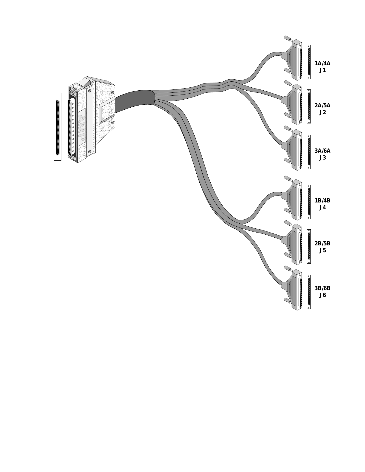
DSU MP Port Connections 9
;;;
;;;
;;;
;;;
;;;
;;;
;;;
;;;
;;;
yyy
yyy
yyy
yyy
yyy
yyy
yyy
yyy
yyy
1A/4A
J1
2A/5A
J2
3A/6A
J3
1B/4B
J4
2B/5B
J5
3B/6B
J6
Figure 2-3 Female D-subminiature 120-pin to Six DB-25 Connector Cable Assembly
Page 18

10 I
NSTALLATION
Network
Connection
The network side of the unit is referred to as the network interface. This interface
contains an ALBO (automatic line build out) that allows the unit to be located a
substantial distance away from the telco network interface with a receive signal
level down to -27 decibels.
The network interface LBO level should be set as instructed in Line Build Out on
page 19. Maximum suggested cable lengths for the connection from the unit to the
network are listed in the following table. Calculations are based on a cable
temperature of 70°F, 0.083-µF/mile capacitance, a 27-dB loss, and a 100-Ω,
non-loaded, twisted pair cable. PIC refers to Plastic Insulated Cable.
Ta b l e 2-2 Network Cable Characteristics
Cable Type Loss per 1000' Max Cable Length
26 gauge PIC 6.8 dB 4,400 ft
24 gauge PIC 5.4 dB 5,500 ft
22 gauge PIC 4.2 dB 7,100 ft
19 gauge PIC 3.0 dB 10,000 ft
The network physical interface is a standard RJ-48C connector with the pinouts
assignments shown in Table 2-3.
Ta b l e 2-3 T1 Net Connector Pinout
Network
Disconnection
Alarm
Connection
External Clock
Connection
Pin T1 NET Interface
1, 2 Data In
3, 6 Not used
4, 5 Data Out
7, 8 Chassis Ground
In accordance with FCC Rules, Part 68.218 (b), the user must notify the telephone
company before disconnecting the unit.
Alarm conditions detected by the unit are conveyed at the isolated Alarm Relay
output contacts on the rear panel. NC (Normally Closed) and NO (Normally Open)
refer to the alarm contact’s relationship to C (Common) under a no-alarms
condition.
Alarm connections are made to the terminal strip using a 22- gauge stranded, or
similar wi re. The Normally Closed alarm co nnects to NC & C. The Normally
Open alarm connects to NO & C. Contacts a re rated at 0.6 amperes AC or 2.0
amperes DC . Alarm parameters are discussed on page 55.
If the unit is to receive its timing source from a user-supplied clock other than the
DTE or T1 lines, the Station Clock input must be connected on the rear panel.
This input is designed to accept TTL or bipolar signal levels. The station clock is
commonly available as a 64 kHz, bipolar RTZ signal referred to as a composite
clock.
Page 19

Network M anagement 11
The unit also accepts any unframed all-ones bipolar RTZ signal with a level of 1.5
to 4 volts peak and a frequency of 1.544 MHz or any multiple of 56 or 64 kHz. An
RS423-compatible station clock input, with the sa me range of input frequencies, is
also available as an opti on.
The station timing is configured through the front panel (see Station Tim ing on
page 20) or through the te rminal interface (see Station Timing on page 53). The
pinout of the 6-pin modular jack is shown in the following table.
Ta bl e 2 - 4 TTL and Bipolar Exter nal Clock Connector Pinout
Pin TTL Signal Bipolar Signal
1, 6 Ground Ground
2, 5 not used not used
3 TTL Clock Balance d Tip
4 Ground B alanced Ring
Network
Management
The unit is fully compatible with the TXPORT 8100A Site Manager. The 8100A
software system can manage small to large networks of network access products.
NMS Connection The two 6 - pin modular connectors labeled NMS IN and NMS OUT on the rear
panel may be used for connection to the 8100A. These ports allow the connection
of multiple collocated units in a daisy-chain IN/OUT bus arrangement as shown in
Figure 2-3. The OUT port of one element is connected to the IN port of the next
element, and so on, to form a complete chain among the group of elements.
8100A
Element
Element
Last
NMS
OUT INNMS
IN OUT
IN OUTNMS
IN OUTNMS
Figure 2-3 NMS Daisy-Chain Arrangement
All units on the same NMS chain must use the same NMS bit rate.
The NMS IN connector provides both the transmit and receive signal pair. This
port may be used for a modem connection or as a VT100 terminal interface (see
System Description on page 35).
Page 20
12 I
NSTALLATION
The NMS address, NMS bit rate, and boot configuration mode are set by the front
control panel as described in page 33. The physical connection of the NMS port is
a 6 - pin modular connector with the pinout shown in Table 2-5. This is a serial
RS232-level port configured for 8 bits, no parity, and 1 stop bit.
Ta b l e 2-5 NMS In and Out Pinouts
Pin NMSBUSIN NMSBUSOUT
1, 6 not used not used
2, 5 Signal Ground Signal Ground
3 Data Out Data Out
4 Data In Not Used
Supervisory
Port
Connection
Supervisory Port
Control Out
1
2
Data Out
Data In
Signal Gnd
Control In
3
4
5
6
PRISM 3060 Rear Panel
I
O
The rear panel SUPV port serves several functions. The terminal interface program
may be accessed through this port. A modem may be connected to this port for
remote access or use of the call-on-alarm feature (see Figure 2-4).
Terminal (DTE)
DB-25
20
21
22
23
1
2
TXD
3
RXD
4
RTS
5
CTS
6
Signal
7
GND
Supervisory Port
Control Out
1
2
Data Out
Data In
Signal Gnd
Control In
3
4
5
6
PRISM 3060 Rear Panel
I
O
Modem (DCE)
DB-25
20
21
22
23
1
2
3
4
5
6
7
TXD
RXD
RTS
CTS
Signal
GND
NMS IN
may also
be used
RS-232 to Terminal
(PN 9-1001-028-1)
Figure 2-4 NMS Connections to the 3060-10 through a Modem and a Terminal
The supervisory port is an independent serial interface into the unit and plugging
into it does not interrupt the NMS port traffic. The supervisory port bit rate must
be set by the front control panel (see Supv Bit Rate on page 33).
Terminal
NMS IN
may also
be used
RS-232 to Modem
Modem
(PN 9-1001-027-1)
Page 21

Power Connection 13
The physical connection is a 6 -pin modular jack with the following pinout
assignments. The port is a serial RS232-level port configured for 8 bits, no parity,
and 1 stop bit.
Ta bl e 2 - 6 SUPV Port Pinout
Pin SUPV Port Interface
1Control Out
2, 5 Signal Ground
3Data Out
4Data In
6Control In
Power
Connection
The unit is factory equipped with a standard three-prong AC cord and is fused at
1.0 ampere.
Remove power befor e che cking f use s.
On power up, the board initialization sequence causes a delay. During this period, the
message on the front panel shows Calculating Checksum.
Connect the AC power cord to an appropriate AC power receptacle.
1
Set the rear panel power ON /OFF switch to the ON position (labeled l). The green
2
power LED on the front panel should light after the LED initialization sequence
ends. If the indicators do not light, recheck the power connections and the primary
AC circuit breaker. M ake sure the ON/OFF switch is in the ON position.
Page 22

14 I
NSTALLATION
Page 23
3
O
PERATION
Introduction
This chap ter descri bes the screens and menu s ass ociated with the TXPO RT PRISM
3060-10 front panel LCD interface. Chapter 4 discusses the screens and menus
associate d with the external terminal inter face. In gener al, the options are the same
for both interfaces.
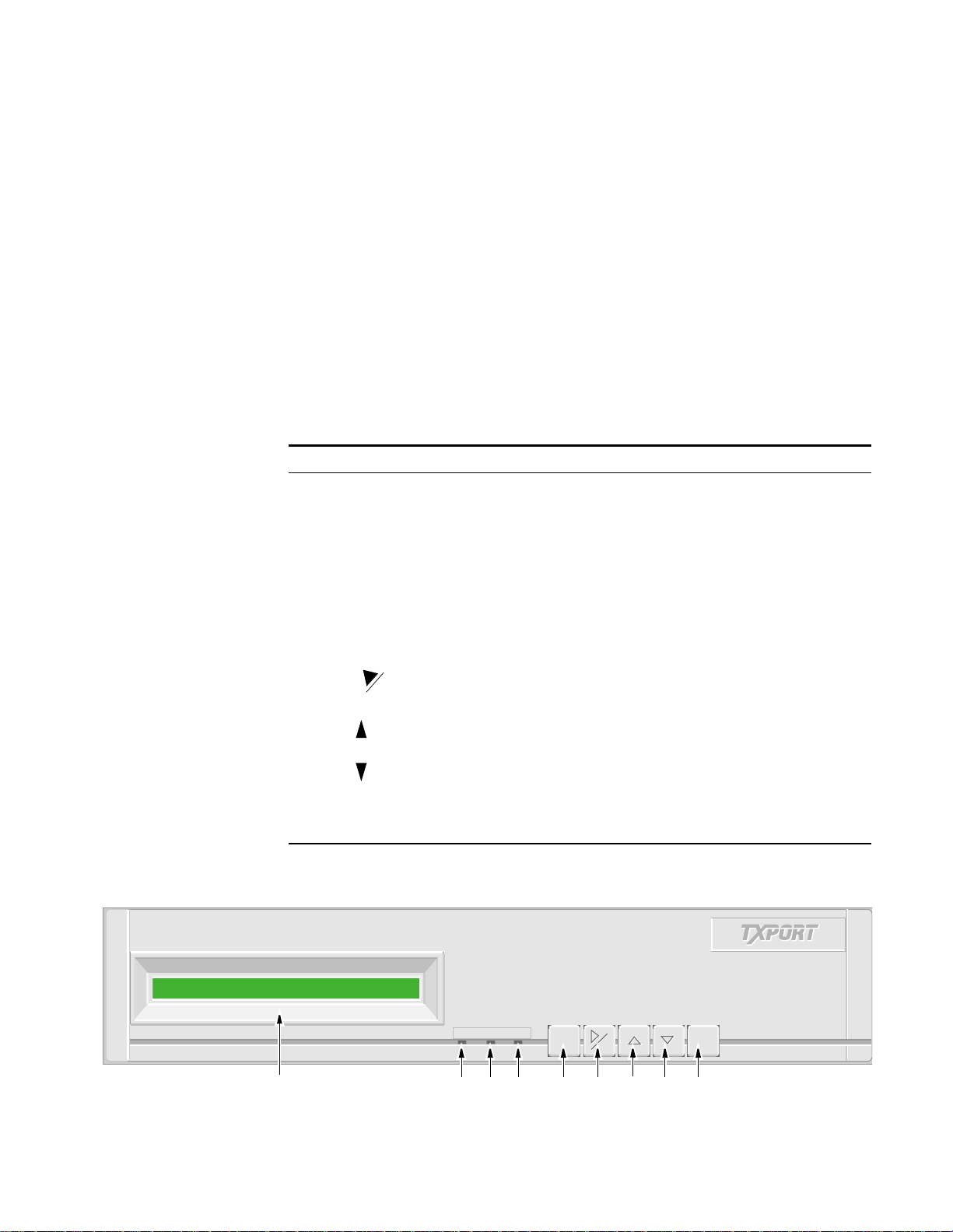
Figure 3-1 depicts the front panel whic h has three LED indicators, an LCD screen,
and five control buttons. Table 3-1 references by number the front panel controls
and indicators and provides a brief description.
Ta bl e 3 - 1 Front Panel Controls and Indicators
Index Control/Indicator Function
1 LCD Display This 2 - line, 40 - character-wide window provides access to
unit configuration, diagnostics, an d utilities.
2 ALARM (red) This LED lights continuously when the unit is in an active
alarm condition.
3 TEST (yellow) This LED lights continuously when line or DTE loops are set
or if the BERT function is operating.
4 POWER (green) This LED lights continuously when power is applied to the
unit.
5 EXIT Pressing this button returns the user to the previous menu.
6 Pressing this button either moves the cursor one character to
7 Pressing this button allows the user to scroll up through the
8 Pressing this button allows the user to scroll down through
9
CLR
SELECT
the right or it clears the error counts. Pressing this button on
power up resets all parameters to the factory defaults.
elements/parameters.
the elem ents / p aramet ers.
Pressing this button acc esses a subm enu or sets a para meter
to the displayed value.
1
Figure 3-1 3060 Front Panel
ALARM TEST POWER
ALARM TEST POWER
2 3 4 5 6 7 8 9
EXIT
EXIT
CLR
CLR
SELECT
SELECT
Page 24

16 O
PERATION
Throughout this manual, all the factory default settings are shown underlined.
Front Panel
Operation
Maintenance
Reset
After power is applied and the unit performs a self test, the idle display screen
appears as shown in Figure 3-2. The top display line is text that may be user
programmed (see User Info/Unit ID on page 33). The bottom line displays the unit
serial number and the hardware and software revision numbers. The unit may be
accessed by pressing any front panel key.
TXPORT Prism 3060
S/N: 012345 HW Rev05.01 SW Rev02.52
Figure 3-2 Idle Display Screen
The PRISM 3060 -10 provides non-volatile memory retention of unit configuration
in the event of power failure. This feature allows the unit to automatically restore
normal service following a power loss. Note, however, that when the unit is stored
without power for an extended period, the battery may drain and some parameters
may becom e corrup ted.
Therefore, when the unit is first received for installation or if power has not been
applied for an extended period, a factory default maintenance reset operation
should be performed. This is done by pressing and holding the CLR button a nd
then applying power to the unit. Hold this key until the RAM CLEARED message
appears. This procedure installs the predefined ROM configuration to eliminate the
possibility of data corruption. The battery is fully charged after power has been
applied for 120 hours.
The maintenance reset operation sets all parameters to the factory default ROM
settings and zeros all perfor mance registers.
Password If no password has been programmed, the password prompt does not appear and
the PRISM 3060 -10 proceeds directly to the menu system. The unit is factory
shipped without a programmed password. The process of setting a password is
described in Edit Password on page 32.
If a password has been programmed, the password sc reen appears when any key is
pressed. Each character must be entered using the up and down arrow keys until
the desired charact er is di spla yed. Us ing the u p arrow, the characters s croll throu gh
0 to 9, A to Z
, and
a to z
for a t otal of 62 distinct c haract ers. When the corre ct
character is display ed, press the right arrow to m ove the curso r to the next
position. The preceding character is accepted and disappears.
Enter Password: A
/ =Letter Select=Done = move
Figure 3-3 Password Screen
Continue this patter n until t he last ch aracter i s selected. Press t he right arrow once
more and then press Select. If the password is correct, the unit advances into the
menu system. If the password is entered incorrectly, the idle display is returned
and the user may try again.
Page 25

Front Panel Operation 17
The password is case sensitive. Lower-case and upper-case characters must be
entered exactly as they were programmed.
Menu
Components
The PRISM 3060-10 front panel display consists of three components: a menu
title, a menu element, and a cursor. These components are shown in Figure 3-4
using t he Main M enu as an example.
Main Menu
Diagnostics
>
Cursor
Figure 3-4 Main Menu Screen
Menu Element
Menu Title
Menu Title
The menu title is the general classification of functions currently accessible to the user.
Menu Element
There are three types of menu elements. In this manual, the distinction is made by
the box type shown in the menu diagrams.
✦ A large, solid box indicates user-selectable menus with lower-level menu items.
✦ A dashed box lists user-selectable parameters. Pressing Select exe cutes the
displayed configuration.
✦ A small, solid box (with small type) indicates either a non- se lectable status or a
field in which a particular value may be entered.
For example, refer to T1 NET Configuration Menu on page 19. The upper-level
menus are shown within a large, solid box. This indicates that these items are
user-selectab le menus . The lower level menus are shown wit hin dash ed boxes to
indicate that these items a re user-selec table para meters . The sma ll, solid b oxes
under Alarm Thresholds indicate that values may be entered in these fields.
If the menu element contains a submenu, it is accessed by pressing Select. The
menu element becomes the menu title and the next lower level in the hierarchy
become s the men u elemen t. For exampl e, if the m enu e lement is T1 NET
Configuration, pressing Select moves T1 NET Configuration up to the menu-title
level and Framing Type moves up to the menu-element level.
Cursor
The cursor first appears on the left side of the display as seen in the upper screen
of Figure 3-5. W hen the element is a user-selectable function, pressing Select
Page 26

18 O
PERATION
moves the cursor to the right with the arrow pointing left (<) as seen in the lower
screen.
T1 NET Configuration
Frami n g Type ........ .. E S F
>
T1 NET Configuration
Framin g Type ......... . ES F
Figure 3-5 Example of Cursor Movement
<
This allows the user to scroll through the options available for that function using
the arrow keys. Pressing Select again sets that parameter. Pressing Exit returns the
cursor to the left. The cursor does not appear when status-only elements are
displayed.
To return to the previous screen without changing a parameter, press Exit. Do not
press Select. Pressi ng Exit again returns the previous screen.
Main Menu
Display
Throughout this manual, all the factory default settings are shown underlined
.
The Main Menu screen is the first level of access for all the functional menus
available to the user. To a ctivate any of these menus or submenus, use the methods
described in Menu Components on page 17. The Main Menu diagram is shown in
Figure 3-6.
MAIN MENU
T1 NET
Configuration
Figure 3- 6 Main Menu Diagram
DTE Port
Configuration*
Diagnostics System
* Dependent on installed options.
Log OffLog On
Utilities
Page 27

T1 NET Configuration 19
T1 NET
Configuration
Framing
Type
ESF
D4
Line
Code
AMI
B8ZS
The T1 NET Configuration screen (Figure 3-8) allows setting the following
network configuration parameters.
Defaults are shown underlined.
Line
Build
Out
0 dB
-7.5 dB
- 1 5 dB
-22.5 dB
Timing
Internal
Network
T1 DTE
Station
Slot X /Port Y,
(where
X = 3 to 6 and
Y = A or B)
Station
Input
Timing
1.544
MHz
N×56 K
N×64 K
(Station
Timing
must be
selected)
Figure 3-7 T1 NET Configuration Menu
T1 NET Configuration
Line Code ............. AMI
<
Station
Timing
Selects the
N
multiplier
(1 - 24)
for the
Input
Timing.
PRM
Enable
Enable
Disable
Zero
Suppress
Enable
Disable
Alarm Reset 030
Alarm
Thresholds
ES 045
SES 005
LOSS 005
OOFS 005
UAS 000
RAS 000
AISS 000
BPVS 000
Figure 3-8 T1 NET C onfiguration Screen
Framing Type Selects the framing for the T1 network. The choices are D4 and ESF
Line Code Sets the network side line coding. The choices are AMI and B8ZS
.
Line Build Out Sets the line build out for the network interface. The choices are 0 dB
-15 dB, and -22.5 dB.
Timing Sets the timing source to synchronize the unit’s internal timing generators. In all
cases, slips are controlled to occur on frame boundaries at the network and /or
DSX1 ports when timing synchronization is lost. The choices are as follows.
INTERNAL
The unit’s internal freque ncy standard is used for all timing.
NETWORK
Timing is derived from the network-recove red clock (the most common selection
for most applications).
STATION
.
, -7.5 dB,
Timing is derived from a bipolar- or TTL-compatible clock supplied to the unit
through the rear panel. This field shows the input tim ing and only appears when
Page 28

20 O
PERATION
Station has been selected from the Timing menu. The choices are N ×56K,
N×64 K, and 1.544 MHz.
PRM
Enable
Zero
Suppression
Station Timing.
When Station Tim ing is set to either N×56K or N ×64K, the N
multiple must also be selected. This field only appears when Station has been
selected from the Timing menu. The N range is 1 to 24. For example, if N = 2 and
Station Input Timing is set to N×64K, the unit expects a 128 kH z clock on the
station input port (2 ×64 = 128).
SLOT X, PORT Y
Timing is synchronized to the external terminal timing clock
.
supplied from the DTE and connected to the selected port. Selections only appear
for ports installed in the unit. Ports are indicated as Slots 3, 4, 5, and 6 for the
3060 -10; DSU: 1 through 6, and port:A or B.
STA CLK Connector
When this mode is selected, the timing rate must also be set from Station Input
Timing.
This field
ENABLE
s or
DISABLEs
the ANSI T1.403 Performance Report Message
functions.
Determines whether ones density insertion is activated after 15 zeros. To ensure
compliance with TR 54016, this field must be enabled. The choices are
and
DISABLE
.
ENABLE
Alarm
Thresholds
The unit can be programmed to generate an alarm condition based on a specific
level of performance degradation. Acceptable alarm thresholds are set for periods
of 15 minutes (900 seconds). The error types listed in the following paragraphs can
be preset to a value between 0 and 900 seconds. A field set to 0 causes the unit not
to alarm o n that st atistic. To effectively disable alarm report ing, set al l fields to 0 .
The 15 - minute time frame is not
based on the TR 54016 or T1.403 interval
boundaries, but is a time window based on the accumulated counts over the
previous 15 one - minute intervals. In all cases, if the number of actual networkerrored seconds in the previous 15 minutes reaches the preset threshold for the
specified error type, an alarm condition is declared.
Alarm Reset Timer
Sets the length of time after the alarm condition clears before the alarm indication
is removed. A valu e of zero in this fie ld does n ot allow the alarm to b e
automatically c leared. The default value is 30 seconds
.
ES
Sets the errored seconds threshold. The default value is 45 seconds
.
SES
Sets the severely errored seconds threshold. The default value is 5 seconds
.
Page 29

LOSS
T1 NET Configuration 21
Sets the loss of signal seconds threshold. The default va lue is 5 seconds
OOFS
Sets the out of frame seconds threshold. The default value is 5 seconds
UAS
Sets the unavailable seconds threshold. The default is 0
(disabled).
RAS
Sets the remote alarm seconds threshold. The default is 0
(disabled).
AISS
Sets the alarm indication signal seconds threshold. The default is 0
(disabled) .
BPVS
Sets the bipolar violation errored seconds threshold. The default is 0
(disabled) .
.
.
Page 30

22 O
PERATION
DSU MP Configuration
Por t # This parameter allows selecting the configuration of the slot (3, 4, 5, or 6 for the
The DTE Port Configuration display (Figure 3-9) allows configuration parameters
to be set for the DSU MP ports.
It is very important that the DTE ports at opposite ends of a link be configured
identically. For example, if port A of one DSU MP is configured for 19.2 kbps async,
then port A at the far end must also be configured for 19.2 kbps async. Neglecting to do
this may not only result in the inability to pass DTE traffic from end to end, but also
misdirect data intended for one port (ex. A) to the opposite port (ex. B) at the far end. This
data swapping is a side effect of the rate-swapping feature and only occurs at DTE rates of
31.2 kbps (in TXP-I mode) and 38.4 kbps (i n TXP-II mode) when units are configured
improperly.
Defaults are shown underlined
.
3060 -10) and the port: 1A through 6A in DDS mode and TXP mode with TDM
turned off; 1A, 1B, 2A, 2B, 3A, 3B, 4A, 4B, 5A, 5B, 6A, and 6B in the TDM
modes.
The following parameters are for the displayed slot, DSU, and port.
DTE Port Configura tion
Slot 5Port 1A Config Menu
DDS
Mode
DDS-I
DDS-II
TXP-I
TXP-II
Port
Transmit
Clock
Internal
External
DDS
Rate
Starting
Channel
Port
Rate
Port
Format
Port
Mode
Type
Number
DDS I, TXP I = 56K
DDSII, TXPII=64K
CTS
Control
For ce True
Internal
Force False
DSR
Control
Force True
Internal
0 to 24
DCD
Control
Force True
Internal
Far RTS
DDS Rate
RTS
Control
For ce True
External
Sync
Async (only
used in one
of the TXP
modes)
Control
NON-TDM
TDM
LL
Lead
Disable
Enable
RS-232C
V. 3 5 (P o rt
A only)
EIA-530
(Port A
RL
Control
Lead
Disable
Enable
≤
Figure 3-9 First DSU MP Configuration Screen and Menu Diagram
Port
only)
V.5 4
Loop
Enable
Disable
Alarm on
DTR Loss
Disable
Enable
Page 31

DSU MP Configuration 23
DDS Mode The unit can operate in one of four DDS modes on two types of DDS lines.
DDS-I
DDS-I
is a standard mode compliant with industry DDS-I standards allowing the
unit to be end - to -end compatible and interoperate with other ve ndor DDS
compliant DSUs.
DDS-II
DDS-II is a standar d mode that can interope rate with other standa rd DDS-II
equipment.
TXP-I
TXP-I is a proprietary mode for DDS-I lines that require a 41TDM or a PRISM
3060 -10 DSU MP unit at the other end of the line. This mode allows two-port
multiplexing in TDM port mode with an in-band data link.
TXP-II
TXP-II mode is a propriet ary mode for DD S-II lin es that re quire a 41TDM or
PRISM 3060 -10 DSU MP unit at the other end of the line. This mode allows
two-port multiplexing in TDM port mode with an in-band data link.
DDS
Rate
Start
Channel
Number
This field show s the network interfa ce line rate as determined by the DDS mode
and is set as follows depending on the DDS Mode screen. 56K is displayed for
DDS-I or TXP-I m odes an d 64K for DDS-II or TXP -II mode s.
The starting channel in the 24- channel DS1 bit stream must be selected in this
field. Only one channel is used per DSU. The choices are 0 through 24. If 0 is
selected, no bandwidth is assigne d for that port and the port is off.
Page 32

24 O
PERATION
Port
Rate
The Port Rate is less than or equal to the DDS Rate. The default values are 56K
for DDS I and 64K for DD S II. Table 3-2 shows the Port Rate s for variou s modes
and formats.
Ta b l e 3-2 Data Rates
DDS Mode DTE Mode Format Data Rates
DDS-I NON-TDM sync 56K
DDS-II NON-TDM sync 64K
TXP-I NON-TDM async
sync
TDM async
sync
TXP-II NON-TDM async
sync
TDM async
sync
*
Only one port (A or B) can be set to the highest rate at any given time. For example, if Port A is set to
the highest rate, Port B can be set no higher than the next highest rate.
2.4K, 4.8K, 9.6K, 19.2K, 38.4K, 52K, 57.6K
2.4K, 4.8K, 9.6K, 19.2K, 38.4K, 52K
2.4K, 4.8K, 9.6K, 19.2K, 31.2K
2.4K, 4.8K, 9.6K, 19.2K, 31.2K
2.4K, 4.8K, 9.6K, 19.2K, 38.4K, 56K, 57.6K, 60K
2.4K, 4.8K, 9.6K, 19.2K, 38.4K, 56K, 60K
2.4K, 4.8K, 9.6K, 19.2K, 38.4K
2.4K, 4.8K, 9.6K, 19.2K, 38.4K
*
*
*
*
Port
Format
This field shows the data format for the DTE port which can be synchronous
(SYNC
) or asynchronous (ASYNC). Asynchronous can be chosen only if one of
the TXP DDS modes is selected.
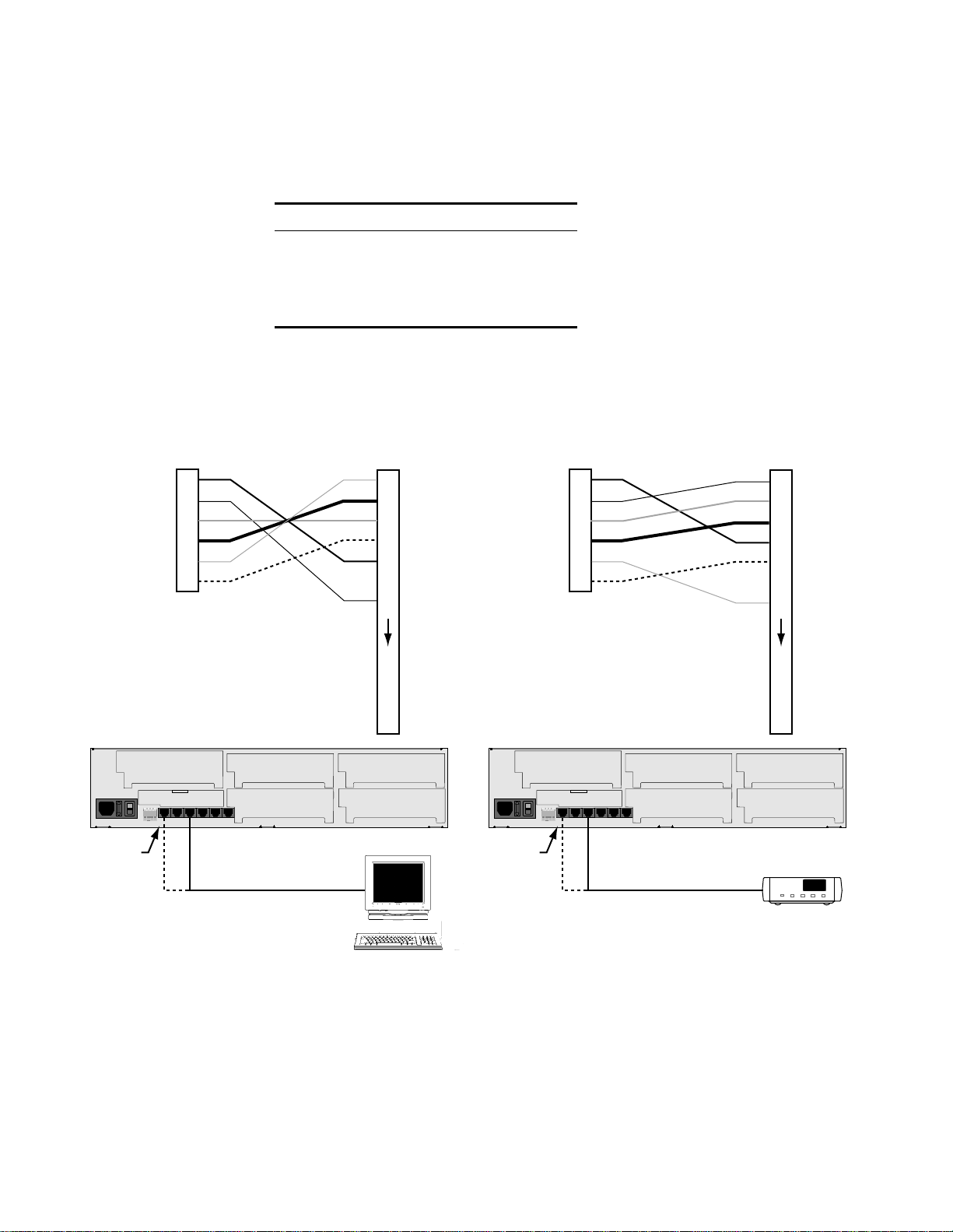
Port Mode The DSU MP interface can operate in either of two modes: NON-TDM
and TDM (time division multiplex).
The DDS Mode must be set to either TXP-I or TXP-II to enable the TDM port mode.
NON-TDM (Port 1A, 2A, 3A, 4A, 5A, and 6A)
In the NON-TDM mode, DTE interface B is disabled allowing DTE interface A to
run at speeds up to the full usable DDS line bandwidth as shown in Figure 3-10.
This option is always available.
DTE Port A T1 DS0DSU
Figure 3-10 NON-TDM Mode Functional Block Diagram
(standard)
Page 33

DSU MP Configuration 25
TDM (Port 1A, 1B, 2A, 2B, 3A, 3B, 4A, 4B, 5A, 5B, 6A, and 6B)
In TDM mode, both DTE interfaces are active and are multiplexed together into
the single DDS network path as shown in Figure 3-11. It allows access to
configuration submenus specific to DTE interface B.
DTE Po rt A
TDM T1 DS0DSU
DTE Po rt B
Figure 3-11 TDM Mode Functional Block Diagram
Port
Type
For ports A and B, the Port Type field displays the installed DTE interface:
RS-232C
, V.35, or EIA-530.
For port B, the interface is RS-232 only.
Port
Transmit
Clock
Used to select the clock that the unit uses to sample the data transmitted from the
DTE. When set to
INTERNAL
clock that is also supplied to the DTE as Transmit Clock. The
uses the external clock supplied by the DTE.
V.54 Loop Selecting Enable
allows the unit to respond to in-band V.54 loop commands. If
Disable is selected, the unit ignores these commands.
CTS Control
and DSR Control
Setting thes e fields to FORCE TRUE
forces the port control lead output state. INTERNAL allows for normal operation.
DCD Control S etting this field to FORCE TRUE
INTERNAL all ows for normal opera tion. Far RTS is similar to INTER NAL except
that in far-end units the RTS lead becomes an additional qualifier. This selection is
only available when in TXP-I or TXP-II mode. When using the Far RTS feature,
ensure that units at both ends are configured for Far RTS. If the unit at the far end
is a 41TDM, its RTS parameter must be set to Normal; if it is set to Force On, Far
RTS does not work.
, the data is sampled directly with the transmit data
EXTERNAL
option
or FORCE FALS E (in DSR mode only)
forces the port control lead output sta te.
RTS Control Request To Send is an input to the unit from the DTE. Clear To Send is an output
from the unit to the DTE. The b ehavior of RTS and CTS is se t as follows. In the
Extern al settin g, the unit reacts to RTS from the DTE. When RTS is on, the unit
transmit s data no rmally an d turns CTS on. Whe n RTS is off, the unit transmit s idle
code to the n etwork and t urns C TS o ff. In the Forc e True sett ing, the unit ign ores t he
state of the RTS lead from the DTE and forces it on internally and forces CTS on.
Alarm on
DTR Loss
Selecting Enable allows the unit to go into alarm on loss of DTR. The default
setting is Disable
.
Page 34
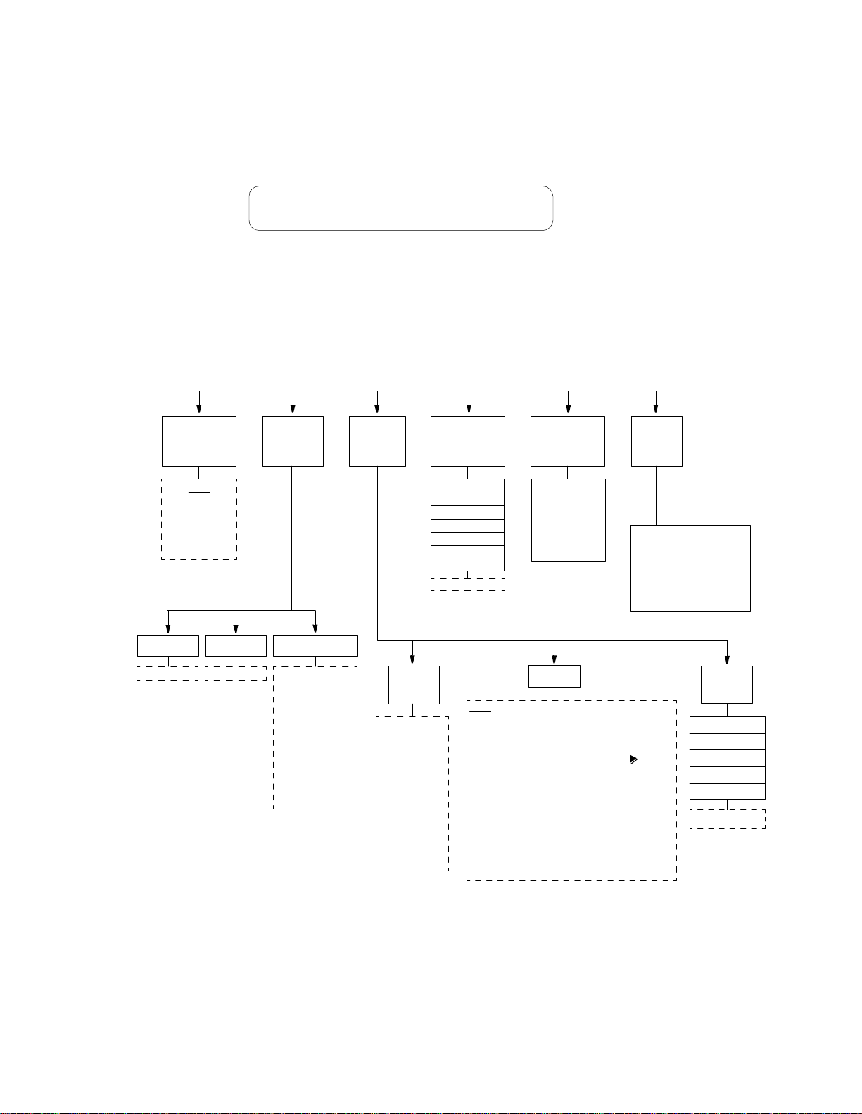
26 O
PERATION
Diagnostics
T1
Network
Loop
None
Loop F a r
Unloop Far
NET PLB
NET LLB
DTE MLB
The Diagnostics screen (Figure 3-12) allows test and maintenance functions to be
performed on the T1 network and the DTE ports. The network interface of the unit
recognizes in-band and FDL out -of -band loopback requests. The DSU MP also
recognizes local testing and remote network management loopback test
configurations (as shown in Figure 3-13).
Diagnostics
> Port Loops
igure 3-12 Diagnostics Screen
Ports in alarm are shown on the DTE Alarms list. Figure 3-13 shows the loops and
BERTS that can be performed on the 3060-10 and DSU MP ports. The 3060-10
and DSU MP also support other loops for other interfaces as shown in Table 3-3
and Figure 3-14.
Port
Loops
BERT
Functions
Network
Performance
Statistics
ES
SES
LOFS
UAS
CSS
BPES
ESF Errors
Clear ESF Stats
Network
Alarms
None
Signal Loss
Sync Loss
AIS
Yellow /R e m o t e
DTE
Alarms
Slot 3, 4, 5, 6
DSU 1 t hr o ugh 6
Port A only in DDS modes
B in TDM modes
Type DTR (tied to a port)
ASC (no A or B, tied
to DSU)
Slot #
3, 4, 5, 6
DSU #
1 through 6
Type
None
Line
PLB
Loop Far V.54
Unloop Far V.54
TDM
DTE-A
Loop Far DTE-A
Unloop Far DTE-A
DTE-B
Loop Far DTE-B
Unloop Far DTE-B
BERT
Pattern
QRSS
63
511 (DSU M Ps
can run on ly
this pattern.)
2047
15
2
20
2
23
2
1:8
3:24
ALT
CLEAR
BERT
None
Idle
T1 Net
Slot 3, 4, 5, 6
DSU Port-Direction (select using )
DSU 1 through 6
Port A only in DDS modes
A and B in TDM modes
Channel 1 through 24 (free channels only)
Note: BERT Port does not appear when no slot is
selected. IDLE and CHANNEL do not appear if all
channels are assigned.
Direction NET and DTE
Figure 3-13 Testing and Diagnostic Functions Available through the 3060-10
BERT
Results
Sync Status
Elapsed T i me
CLR
Bit Errors
Errored Seconds
Pattern Sync Loss
Reset BERT Test
Page 35
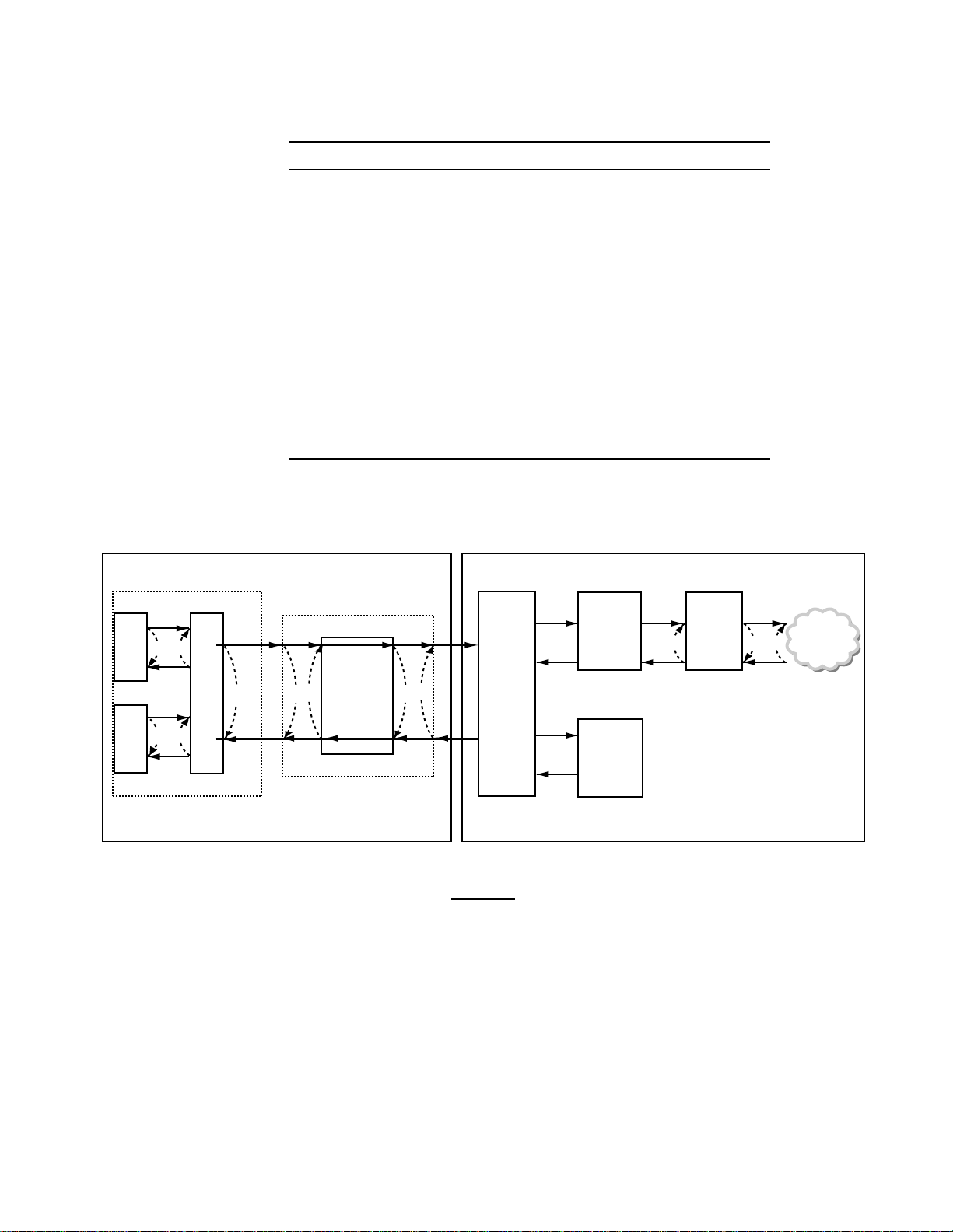
Ta bl e 3 - 3 Test Loops for the 3060-10 and the DSU MP
Loop Type Unidirectional Loop Bidirectional Loops
DSU Line F, G
TDM C
DSU PLB D, E
DTE-A A1 & A2
DTE-B B1 & B2
V.54 Resp ond D, E
DDS I Data (ALB) D, G
(DDS II) DSU Latchin g D, G
DTE Local (LL pin) F, G
NET LLB H
DTE MLB I
NET PLB J
Diagnostics 27
DTE
A
DTE
B
A1
A2
B1 B2
DSU MP T1
TDM
CD
Framing,
CRC, and
FDL
Control
DSU
E
G
F
Multiplexer
BERT
Pattern
Generator
and
Detector
Figure 3-14 Test Loops for the 3060 -10 and the DSU MP
Defaults are shown under lined
.
Network
Interface
J I H
NETWORK
Page 36

28 O
PERATION
T1 Network
Loop
The unit monitors network loopback commands and activates loops based upon
their reception as described in TR 54016 and T1.403. Refer to Figure 3-14 for a
depiction of the loop modes (See also Figure 4-7 and Network LLB on page 47).
Figure 3-15 shows an example of a T1 Network screen. The Diagnostics menu
allows for loopback and BERT functions as explained in the following paragraphs.
Diagnostics
T1 Network Loop ---- Loop Far
igure 3-15 Diagnostics Screen
<
The looping choices are as follows (note that loops cannot be put up or taken
down during a test, but can be established before running a BERT).
NONE
Network loop not present.
LOOP FAR
Sends loop codes over the network to the far-end unit to force it into a NET LLB.
UNLOOP FAR
Sends unloop codes to the far-end unit to remove the loop condition.
Port
Loops
BERT
Functions
NET PLB
The payload loopback selection loops the data back toward the network. Framing,
CRC, and FDL are regenerated and all ones are passed to the DTE ports.
NET LLB
The local loopback selection loops data received from the network back toward the
network. Received data is also passed through to the DTE ports as normal.
DTE MLB
The T1 DTE maintenance loopback loops network data back toward the DTE at
the network interfa ce. Data is also passed through to the network.
Ports are indicated as Slot 3 through 6 and DSU 1 through 6. The looping choices
are only available for DSU MP cards that are installed and configured. Only the
appropriate loops (shown under Type) for a card’s configuration are selectable.
Loops are shown on the DSU MP side of Figure 3-14 and labeled in Table 3-3.
The following menus offer selections for the BERT pattern, type, and results.
BERT Pattern
This fie ld is use d to spe cify which pattern is transmitted toward the port being
tested. The choices are QRSS, 63, 511, 2047, 2
15
-1, 220-1, and 223-1, 1:8, 3:24,
ALT, and CLEAR. 511 is the only choice for the DSU MP.
Page 37

Diagnostics 29
BERT
This field selects the part of the circuit to be tested. The NONE setting disables the
BERT generator. IDLE tests all unassigned channels. The T1 NET setting tests the
T1 network. A particular port can be tested by selecting a Slot, DSU, Port, and
Direction). Channel allow s testing a specific, unassigned DS0 channel.
BERT Results
The following BERT status and error counts are available through this selection.
Network
Perform ance
Stats
Sync Status.
Displays the current state of pattern sync during a test. If no test is in
progress, NO TEST is displayed.
Elapsed Time.
Displays the elapsed tim e since a timed test began. A value is
displayed only when a test is running (in the HH:MM:SS format).
Bit Errors.
Displays the total number of bit errors detected since the test began or
since erro r statist ics were l ast clea red.
Errored Seconds.
Displays the number of errored seconds that have been detected
since the test began o r since e rror stat istics w ere last cl eared.
Pattern Sync Losses.
Displays the number of times during the test period that the
BERT pattern detector lost sync.
Reset BERT Test.
When set to YES, the BERT error counts and elapsed tim e
values are cleared to zero. This parameter then returns to NO automatically.
The unit records performance statistics as described in TR 54016. The unit is
equipped with a dual set of data registe rs with individual resets that maintain these
statistics. One set is accessed by the network service provider (telco). The other set
is accessed by the user through the front panel, terminal interfa ce, or the TXPORT
8100A Site Controller.
Performance data is collected in 15 - minute intervals for the preceding 24- hour
period. The intervals (numbered Int# 00 to Int# 96) are viewed by pressing Select
and using the up and down arrow keys. Interval 00 is the most recently stored
interval and interval 96 is the interval that is 24 hours old. Pressing the Exit or
Select keys returns the cursor to the left. This allows scrolling to another data type.
When a specific int erval is selected for vi ewing perfor mance data, all oth er
parameters reflect that interval until another interval is selected.
Errored Seconds
ES
displays the number of one-second intervals where at least one CRC or
out -of - frame error event oc curred.
Severely Errored Secs
SES
displays the number of one-second intervals where at least 320 CRC errors
were de tected or at least on e out-o f - fr ame event occu rred.
Page 38

30 O
PERATION
Loss of Frame Secs
LOFS
displays the number of seconds that the network interface is out of frame
sync.
Unavailable Seconds
UAS
displays the number of one-second intervals of unavailable service. Counting
begins when 10 consecutive severely errored seconds (CSES) occur and ends when
10 consecutive seconds pass with no SES. The initial 10 seconds are included in
this count.
Controlled Slip Seconds
CSS displays the number of one-second intervals where at least one controlled slip
occurred.
Bipolar Error Secs
BPES displays the number of one-second intervals where at least one bipolar code
violation occurred.
Daily performance data for the parameters listed above appears following the
15 - minute interval listings. It is collected in 24- hour intervals for the preceding
30 - day period. The days (from Day#00 to Day#30) are viewed by pressing Select
and using the up and down arrow keys. Day# 00 is the most recently stored day
and Day# 30 is the oldest day. Pressing the Exit or Select keys returns the cursor to
the left.
ESF Errors
Displays the total number of ESF error events since the counts were last reset. This
value is not recorded by interval. C ounting stops when the value of 65535 is
reached.
Clear ESF Stats
When YES is selected, all user network performance registers are set to zero and
the parameter returns to NO. The telco register set (accessible by the service
provider) is not cleared by this action.
Network Alarms The netw ork interface alarm status is reported as one o f the stat es shown in the
following paragraphs. The front panel alarm indicator and the rear panel alarm
relay contacts are controlled solely by the user-selected alarm thresholds set in
Alarm Thresholds on page 20.
SIGNAL LOSS
Indicates that the T1 receive signal level has dropped below the level that can be
detected.
SYNC LOSS
Indicates that the unit is unable to synchronize on the incoming T1 framing
pattern.
Page 39

AIS
Indicates that an unframed all ones pattern is being received.
YELLOW/REMOTE
Indicates that a remote (yellow) alarm indication is being received.
Diagnostics 31
DTE
Alarms
The DTE alarms are reported as the slot, DSU, port, and type. DTR-type alarms
are por t specific and ASC-t ype alarms are DSU speci fic.
Page 40
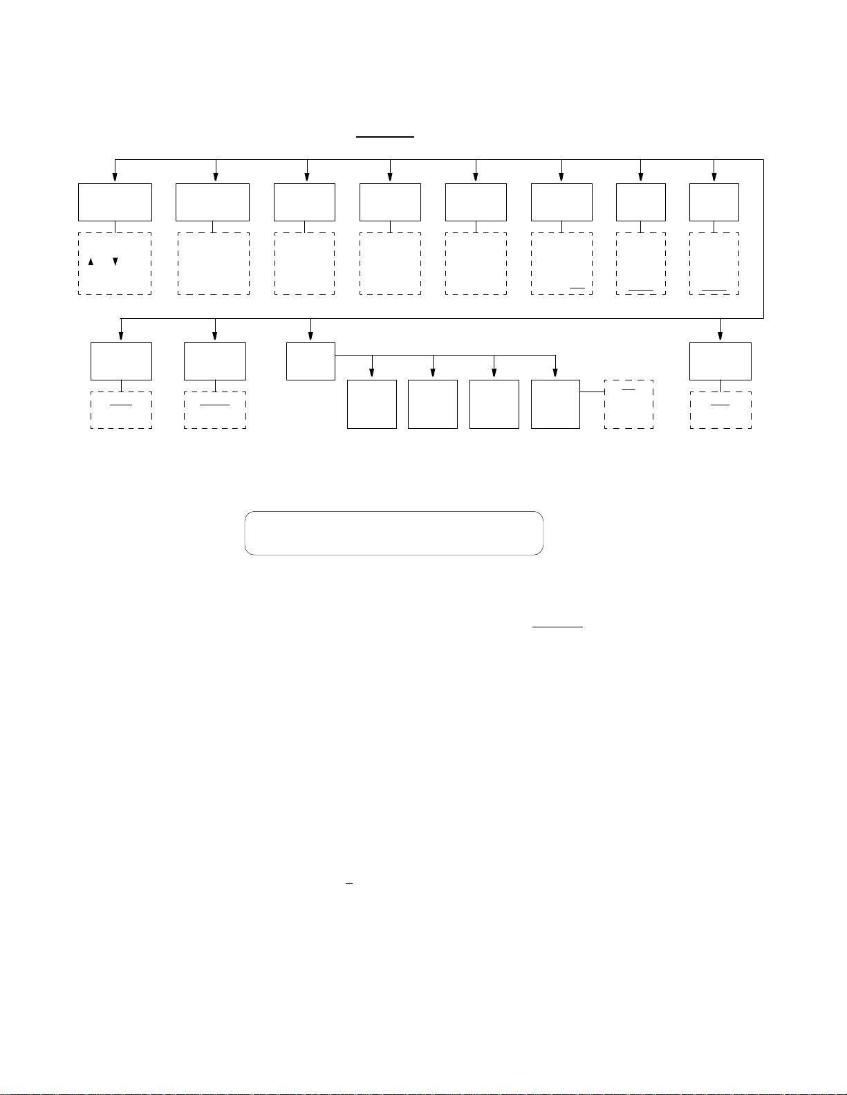
32 O
PERATION
System Utilities
Display
Password
Enter up t o 10
characters using
and keys.
Accept and
move with right
Boot
Mode
Local
NMS
Vi ew Ang le
Adjusts front
panel screen con-
The default value
Alarms
Cut Off
Disable
Enable
The System Utilities displa y (Figure 3-17) allows the user to perform the va rious
functions shown in Figure 3-16 and described in the following paragraphs.
Defaults are shown underlined.
trast.
DateTimeEdit
Enter current
time in
24-hour
HH:MM:SS
format.
Enter current
date in
MM:DD:YY
format.
Call On
Alarm
Edit
Primary
Figure 3-16 System Utilities Menu D iagram
Edit
Second.
User Info
Unit ID
Enter line of
text, such as
site location,
circuit ID for
idle top line
Edit
Element
NMS
Address
Enter 3 di gits
in range of
1 - 250.
The default
value is 251
Alarm
Notifi-
cationString String ID
NMS
Bit Rate
1200
2400
4800
9600
19200
Off
Direct
Dial
Dial NMS
SUPV
Bit Rate
1200
2400
4800
9600
19200
Remote
Link
FDL
Ch. 1 - 24
None
Edit
Password
Display
View Angle
Time The current time is set by entering each digit in the standard 24 - hour
System Utilities
> Edit Password
Figure 3-17 System Utilities Screen
The unit is factory shipped with the password disabled
(factory default). A
password is selected by entering up to 10 alphanumeric characters. Each character
is entered using the up or down arrow keys until the desired character is displayed.
The right arrow moves the cursor to the next position. Continue this pattern until
the last ch aracter i s selected and th en press S elect. Th e password function is
disabled by selecting this field and pressing Select without selecting any
characters.
The password is case sensiti ve. During log on, it must be entered exactly as it was
programmed.
The contrast of the front panel LCD display has a different appearance depending
on whether it is being viewed f rom a high angle or a low angle. Use the arrow
keys to adjust f or the most suitable con trast. T here are 18 s electable valu es, with a
default value of
8
.
HH:MM:SS
format. Each field is range checked and automatically limited to the appropriate
range of values.
Page 41

System Utilities 33
Date The current date is set by entering each digit in the standard
format. Each field is range checked and automatically limited to the appropriate
range of values.
User
Info/Unit
The idle screen top line may be changed in this field. Text is entered using the up
and down arrow keys to scroll through each character and the right arrow key to
ID
change cursor position. The original text can be restored by pressing Exit at any
time during the editing process. The screen is shown in Figure 3-18.
TXPORT PRISM 3060
/ =Letter Select=Done =move
Figure 3-18 User Info/Unit ID Display Screen
NMS
Address
When used with the TXPORT 8100A S ite Controller, each unit connected to the
local daisy chain must be programmed with a unique address in the range of
63
through
. To program a number, scroll through the digits with the up and down
arrow key. P ress the right arrow key to select a digit. A valid NMS address must
be selected before the configuration can be recalled upon start up.
After so ftware has been d ownloaded int o the fla sh memo ry, the RAM must be
cleared. This process sets the NMS address to
251
MM/DD/YY
date
1
.
NMS
Bit Rate
Supv
Bit Rate
Boot
Mode
Alarm
Cutoff
Call on
Alarm
19200
NMS IN
bps.
Sets th e interface s peed for t he
1200, 2400, 4800, 9600
, and
Sets th e interface s peed for t he super visory po rt (
2400, 4800, 9600
, and
19200
bps.
and
NMS OUT
SUPV
ports. The selections are
). The selectio ns are
1200
,
When the unit is powered, configuration is based on this selection. If set to
LOCAL
lost. If set to
, the unit restores the configuration parameters in effect when power was
NMS
, the unit uses the configuration parameters supplied from the
EM8000 element manager database (the unit must have a valid NMS address: from
1 to 250). As shipped from the factory, the unit uses the factory default
configurations stored in the
When this menu item is set to
LOCAL
DISABLE
memory.
, the unit reports a network interface alarm
condition by lighting the front panel indicator and activating the alarm relay
contacts on the rear panel. When set to
ENABLE
, the front panel
ALARM
indicator
still lights during an alarm condition, but the alarm contacts are forced to an
inactive state regardless of the alarm status.
Controls remote alarm reporting. Three submenus are available as follows.
Alarm N otificatio n
Disables alarm reporting.
OFF.
Page 42

34 O
PERATION
Edit
Element ID
Remote
Link
DIRECT.
Sends reports to a printer or terminal connected directly to the
supervisory por t.
Sends reports through an attached AT command set compatible modem
DIAL.
connected to the SUPV serial port, which must dial out to a remote modem.
DIAL NMS.
Calls the EM8000 to dump alarms directly.
Edit Primary and Secondary Dial String
These fields are 18 - character ASCII strings for the call-on-alarm telephone
numbers used in the
DIAL
and
DIAL NMS
modes. The unit makes three attempts
to connect using the primary number. If all three attempts fail, the unit makes three
attempts to connect using the secondary number (if it is not blank). If the
secondary number fails, the unit waits five minutes and then attempts to
communi cate using the prim ary nu mber again . When a connecti on is det ected, th e
unit outputs the notification message (as described in Edit Element ID below ) and
disconnects.
Allows the user to enter a 29 - character ASCII string which identifies the unit to
the device receiving the alarm notification messages.
The unit utiliz es a remote link to communicate with remote units. The facility data
link (FDL) may be used in cases where the T1 path is not routed through
equipment that blocks the FDL. If the network framing mode is set to D4 or the
FDL is not available, a spare channel may be assigned. Possible channel selections
are those that have not been assigned for use with a high-speed port or passed
through to the T1 DTE. The choices are FDL
, None, and Channels 1 to 24.
Log Off
If the unit is not programmed with a password, the user may leave the menu
system by pressing Exit from the Main Menu. If a password has been
programmed, the unit prevents an inadvertent log off by requiring the user to press
Select in the Log Off menu. Once logged into the front panel, the interface
remains active until the user logs out.
Main Menu
Log Off
>
Figure 3-19 Log Off Screen
Page 43

4
T
ERMINAL
O
PERATION
Introduction
System Description
Interface
Connection
This chapter describes the screens, menus, and parameters applicable to the DSU
MP card that are associated with the PRISM 3060-10 terminal interface, an
application program embedded inside those units. Chapter 3 discusses the screens
and menus associated with the front panel interface. Although the options are
essentially the same for both interfaces, the terminal interface shows more
paramet ers on each screen.
The Terminal Interface requires an ANSI-compat ible VT100 terminal (ASCII), or
a computer running an ANSI terminal emulation program. The Terminal Interface
utilizes ASCII break and escape functions, which are implemented differently by
the various terminal emulation programs. The documentation supplied with the
terminal emulation program should be consulted for further reference.
In addition to the TR 54016 and T1.403 protocols, proprietary messages can be
sent over the facility data link (FDL) from the near-end unit to the far-end unit. A
local RS-232 terminal connected to the unit may access a far-end unit. Thus, the
remote unit may be queried for status and statistics, configured, or looped for
testing as if the terminal is connected to it directly.
The terminal may be connected to eith er of two 6 -pin serial RS-232 ports on the unit.
One of the m odula r ports is a pair of daisy-ch ain type r ear pane l connector s labele d
NMS IN
further informat ion. C a bles are available for m ost ty pical c on nections. Standard ca bles
and ordering numbers are listed in Ordering Numbe rs on page 66. Contact TXPORT
for a ny as s istan ce in cab l e sel ec tio n.
. The other port is labeled
SUPV
. Refer to NMS Connection on page 11 for
A serial bit rate of 1200, 2400, 9600, or 19200 bps may be selected using the front
panel control (see Supv Bit Rate on page 33) .
Both serial ports support the same custom protocols which allow the terminal
interface or the TXPORT 8100A Site Controller to request and receive
performance and configuration data from the unit. The unit automatically
determines which protocol is ne eded.
Page 44

36 T
ERMINALOPERATION
Modem
Compatibility
Screen
Components
The terminal interface supports use of an AT command set compatible modem on
either, or both, of the
NMS IN
and
SUPV
serial ports. The modem should be
optioned to ignore DTR, enable auto answer, inhibit command echo, and return
verbose result codes.
If the user calls the unit and sends the
message, the modem hangs up.
break
command before receiving the
connect
Terminal interface screens have several components common to all screens and is
discussed individually in the following paragraphs. These common elements are
shown in the Password Screen (Figure 4-1).
3060 DSU x.xx/x.xx PRISM 3060 Date: MM/DD/YY
No Far End Response TXPORT Prism 3060-10 Time: HH:MM:SS
-------------------------------- PASSWORD SCREEN -------------------------------
Enter Password: (**********)
Start Date: MM/DD/YY
Start Time: HH:MM:SS
Messages
Figure 4- 1 Password Screen
Device Type and Revision
The device type (the PRISM 3060) and the revision control numbers are shown in
the upper left corner. The first number is the hardware revision and the second
number is the software revision. Information is displayed for the near-end unit
(connected directly to the terminal) on the top line, and for the far-end unit
(connected to the network T1 interface) on the second line. Refer to this
information when contacting the factory with inquiries.
The far-end information is available only for TXPORT products that support a
proprietary message set. If the far end does not support these messages but does
support the standard TR 54016 protocol, then the far-end information is displayed
as
GENERIC 54016 FAR END
or TR 54016 messages, then
echoes the FDL messages transmitted by the near-end unit, then
LOOP
is displayed.
. If the far end does not respond to either proprietary
NO FAR END RESPONSE
is displayed. If the far end
FAR END LINE
Page 45

Syst em De scri ption 37
Date/Time
The top right co rner of th e termin al screen d isplays the curr ent date and time. The
setting of these functions is described in Set Tim e and Set Date on page 63.
Elemen t ID
Below the header (PRISM 3060), the Element ID is displayed (see Element ID on
page 64).
Menu Title
The menu title (third line, center) denotes the general classification of functions
currentl y accessibl e by the user (s uch as A larms or P erforman ce).
Messages
This line may display diagnostic messages.
Interface Start-Up On ce a co mpatible terminal is prope rly conn ected to t he unit, a Terminal Interface
session is started by sending a break command or pressing Enter four times to the
unit. If the NMS port is used, the unit then responds with the prompt Enter Unit
Address. To activate the first (or only) unit, simply press Enter. To select a specific
unit, enter the address number of the desired unit and press Enter.
The Enter Unit Address prompt times out after 10 seconds. If this happens, send
another break. To select another unit, exit the current Terminal Interface session,
send a break, and repeat the process. If an invalid address is entered, that address is
echoed back to the terminal. Send another break to start a new session.
The Main Menu screen (Figure 4-2) is then displayed if no password has been
specified. The Utilities menu (page 62) explains setting the password. In the
Page 46

38 T
ERMINALOPERATION
Password screen (page 36), enter the correct password to obtain access to any
other menu. Note that the password is case - sensitive.
3060 DSU x.xx/x.xx PRISM 3060 Date: MM/DD/YY
3060 DSU x.xx/x.xx TXPORT Prism 3060-10 Time: HH:MM:SS
-------------------------------------- MAIN ------------------------------------
Element: [ ]
Alarms
Performance
Maintenance
Configuration
DDS Status
Utilities
Cursor
Controls
------------------------------------Messages-----------------------------------Local Screen
igure 4- 2 Main Menu Screen
The terminal interface uses a highlighted cursor to select from menus and fields
within screens. The cursor is moved in diff erent ways, depending on the terminal
emulation program used. Most programs allow use of the tab and shift+ tab keys.
Others allow use of the four arrow keys. Once a field is highlighted, it is
manipulated as described in Field Type s.
For keyboa rds without these standard keys or only some of them, an alternate set
of cursor control commands is provided. Each command is performed by pressing
a letter key while holding down the Control key. Alternate commands may be
freely mixed with the keyboard commands at the user’s discretion.
Ta b l e 4-1 Keyboard /A lternate Commands
Keyboard Command Alternate Command
Left arrow Control +S
Right arrow Control+D
Up arrow Control+E
Down arrow Control+X
Backspace Control+H
Delete Control+Z
Page 47

Password Screen 39
Field Types Each scre en is m ade up o f fields. The two basic field types are user-sel ectable an d
display only. If the highlighted cursor can be moved to a field, it is a
user-selectable field. All other fields are for displa y only. User-selectable fields
allow for changes to be made or commands to be executed.
Fields without brackets or parenthesis are display only. They cannot be changed on
the scree n. Mos t user-selecta ble fields ar e enclosed in brack ets or pa renthesis and
are described in the following paragraphs.
Fields enclosed in brackets [ ] offer the user a list of selections. The selections
may be toggled by pressing the spacebar. Each time it is pressed, a new item
appears. When the appropriate choice is displayed, press return to select it.
Manipulate fields enclosed in parenthesis ( ) by either of the following methods:
✦ Pressin g Enter on such fields as (Res et) and (S tart Test) simply execut e the
function.
✦ The most common type of field in parenthesis accepts alphanumeric characters.
Ty ping ch aracters when the fie ld is high lighted c auses new c haracters t o repla ce
the curre nt entry. To edit an existing entry rather t han repl ace it, pre ss the ri ght
arrow key to m ove the cursor to the p oint that needs ed iting. Ch aracters may the n
be inserted or deleted. Typed data is always inserted rather than typed over. If the
field is full, though, at least one character must be deleted to add another.
Password Screen
Main Menu
Screen
Many fields of this type may also be toggle d by pressing the spacebar. Other fields
are rang e checked, where t he user is not allowed to exit wit h an illegal valu e set.
Any screen may be redisplayed (or refreshed) by pressi ng Control+U. Any changes to fields
on a screen, that have not been activated by pressing Enter, are discarded.
In the 3060 -10, if no password has been programmed the password prompt does
not appear and the 3060-10 proceeds directly to the menu system. The 3060-10 is
shipped without a programmed password. The process of setting a password is
described on page 63. Figure 4-1 on page 36 shows a password screen.
The Main Menu screen (Figure 4-2) lists the functional user- accessible menus. To
activate any menu, highlight the desired selection and press Enter. This menu and
any subsequent menu may be exited by pressing Escape. If the Main Menu is
exited, the terminal interface program terminates. This is a valid way to end a user
session. If any other menu is exited, the previous screen is returned.
Page 48
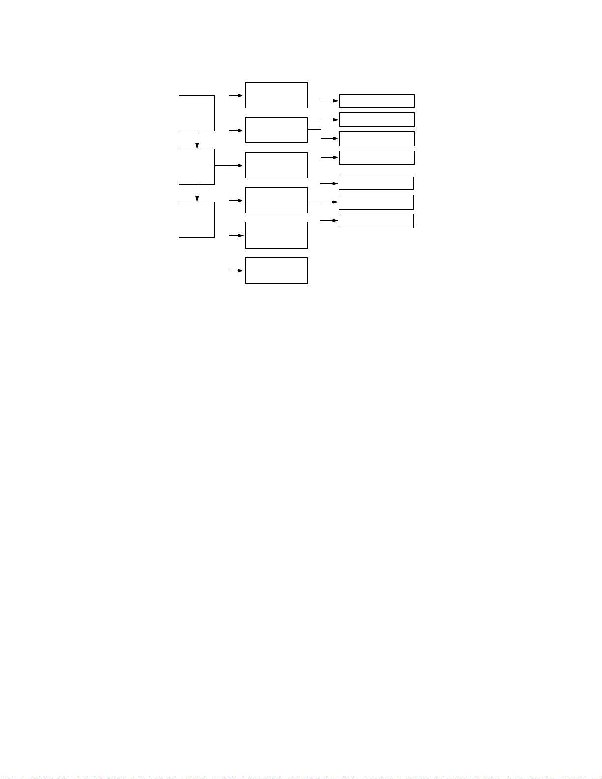
40 T
ERMINALOPERATION
The menu structure (Figure 4-2) shows the screen s access ible from the Ma in
Menu.
Alarms
Standard 24-Hour
Log
On
Enhanced 24-Hour
Performance
Standard 30-Day
MAIN
MENU
Log
Off
Maintenance
Configuration
Enhanced 30-Day
Line Parameters
Alarm Parameters
Port Parameters
DDS Status
Utilities
Figure 4-3 Menu Structure
If no key is pressed for 10 minutes, the terminal interface logs off automatical ly. To
manually log off, press Escape from the Main Menu.
Element This field appear s on all s creens and allows ac cess for ei ther the near-end or
far-end units. This field only appears when there is a far- end (T1 or DDS)
equipment link. Use the spacebar to make the appropriate selection.
Page 49

Alarms Screen 41
Alarms Screen
The Alarms screen (Figure 4-4) allows viewing the alarm status of the network and
the DT E lines. T he DTE Alarms field is descr ibed as fo llows.
3060 DSU x.xx/x.xx PRISM 3060 Date: MM/DD/YY
3060 DSU x.xx/x.xx TXPORT Prism 3060-10 Time: HH:MM:SS
---------- ------------------------- ALAR MS -------------------------------------
Element: [ ]
NET Alarms: NONE
DTE Alarms: OK
Current Threshold
Loss of Signal Seconds (LOSS) 0 5
Errored Seconds (ES) 2 45
Severely Errored Seconds (SES) 2 5
Unavailable Seconds (UAS) 0 0
Out of Frame Seconds (OOFS) 0 5
Remote Alarm Seconds (RAS) 0 0
AIS Seconds (AISS) 0 0
BPV Seconds (BPVS) 0 0
DTE LOS/OOF Seconds (LOSS) 0 0
Power Loss Seconds (PLS) 0 0
Reset Alarm Registers (RESET)
------------------------------------Messages-----------------------------------Local Screen
igure 4-4 Alarms Screen
NET Alarms Thes e statu s lines d isp lay the se lected elem ent’s current net work/D TE sign al alarm
state. Al arms ar e determin ed by the user-select able thres holds lis ted in Table 4-2.
Ta bl e 4 - 2 Alarm Indications
Alarm Description
NONE No alarm threshold has been exceeded, although
errors ma y exist that do not exceed thresholds.
ERRS Th e Errored Seconds, Se verely Errore d Seconds , or
Bipolar Errored Seconds threshold is exceeded.
LOSS The Loss Of Signal Seconds threshold is exceeded.
OOFS The Out Of Frame Seconds threshold is exceeded.
RAIS The Remote Alarm Seconds threshold is exceeded.
AISS The Alarm Indication Seconds threshold is exceeded.
UAS The Unavailable Seconds threshold is exceeded.
Page 50

42 T
ERMINALOPERATION
DTE
Alarms
This statu s line display s the selected ele ment’s current DTE sig nal al arm state. T he
Alarm State for the DSU MP port is shown on the DTE Alarms Status Line as
slot, DSU, port, and alarm type, for example, 2-3A-DTR and 2-3-ASC. ASC,
FDL, and LOS are DSU specific. LOS alar m is the loss o f signal from the far end.
LOS and FDL are only detectable in TXP-I an d TXP-II modes. FDL alarm is
shown when CRC errors are detected within the FDL.
DTE Alarm can be enabled or disabled in the DSU MP Configuration Screen at
the Alarm on DTR Loss pa rameter. If DTE Alarm has more alarms than fit on one
line, square brackets ( [ ] ) appear on the ends of the line and the field scrolls by
pressing the spacebar.
(Alarm sta tus) The main body of the Alarms screen shows the current count for parameters that
may be used to trigger an alarm.
The Current column shows the total of the preceding 15 one- m inute intervals. At
the end of each one -minute interval, the oldest minute of the 15 - minute interval is
discarded.
The Threshold column shows the values set in the Alarm Configuration screen
(Figure 4-13 on page 4 -55). Any parameter that has a current value equal to or
greater than its non-zero threshold generates an alarm. Any parameter with a
threshold value of 0 is disabled from generating alarms.
Pow er Loss
Seconds
Reset A larm
Registers
The parameters shown on the Alarms Screen are updated at five-second inter vals.
Displays the number of seconds that the element has been without power since this
value was last cleared.
Pressing Enter on (
RESET
) zeros the value of all
Current
alarm parameters, but
does not affect 24 - hour or 30 -day performance registers.
Page 51

Performance Screens 43
Performance Screens
The Performance screens displa y a detailed history of the error parameters that are
continuously monitored. The terminal interface provides display of near- end or
far-end performance data using the facility data link.
The unit is equipped with a dual set of performance data registers that hold line
statistics for both the telco and user. Each register set provides detailed status and
performance history for the network and DTE interfaces.
The system has four Performance screens. The STANDARD 24 HOUR and the
ENHANCED 24 HOUR screens allow the user to view the 24 - hour detailed
performance history of the T1 circuit. The only difference in the two screens is in
the type of performance data displayed. The STANDARD 24 HOUR screen is
shown in Figure 4-5.
3060 DSU x.xx/x.xx PRISM 3060 Date: MM/DD/YY
No Far End Response TXPORT Prism 3060-10 Time: HH:MM:SS
------------------------------ 24 HOUR PERFORMANCE -----------------------------
Element: [NEAR] Status: OK
Target: [USER ][NET] Completed Days: 12
Error Events: 302 (RESET) Completed Intervals: 6
(RESET PERFORMANCE REGS) 24 Hr.% Error Free: 91.7
[STANDARD 24 HOUR]
362 2 362 0 2 3 3
24 Hour 6 2700 0 2 3 0
30 Day 30 0 20 12 23 13
PAGE-UP
--------------------------------------------------------------------------- Time INTERVAL ES UAS BES SES LOFC CSS
PAGE-DN
--------------------------------------------------------------------------- 13:30 6 1 900 0 0 1 0
13:15 7 2 900 0 0 3 3
Figure 4- 5 Typical Performance Screen
The STANDARD 30 DAY and the ENHANCED 30 DAY screens allow the user to
view a 30 - day history of a particular element’s performance. These screens
reference interva ls by date rather than by time. To reach each of the four screen
types, use the spacebar to toggle the STANDARD 24 HOUR field. The other fields
are described as follows.
Element Pressing the spacebar toggles this field for selection of eithe r the
unit as the source of performance data or the target of commands.
FAR
the unit the terminal is connected.
refers to the unit at the other end of the
network T1 span.
NEAR
NEAR
FAR
or
refers t o
Target This two - part field determines which section of the circuit is presently displayed
by toggling the spacebar. Telco registers are for viewing only and may not be
changed. The four options are as follows.
Page 52

44 T
ERMINALOPERATION
Error
Events
Reset
Performance
Registers
Standard
24 Hour
USER NET.
USER DTE.
TELCO NET.
TELCO DTE.
Displays the running total of ESF error events for the circuit selected in
and is applicable only when
reaches 65535 or is reset by pressing Enter with the (
Allows the element registers to be reset and may only be used when the
field is set to
DELETE ALL PERFORMANCE DATA?
(NO!) (YES)
Display the user performance registers for the network.
Display the user performance registers for the T1 DTE.
Display the telco performance registers for the network.
Display the telco p erform ance registers for the T 1 D TE.
Target
is set to
USER
. If Enter is pressed, the following warning appears:
USER
. This count accumulates until it
RESET
) field highlighted.
Element
Target
To exit this screen without performing the reset function, press Enter with NO
selected. To proceed with the reset function, press Enter on YES. All va lues for the
chosen regi ster set (NE T or DT E) are then rese t to zero.
To ggling this field with t he spa cebar step s through the fou r available perform ance
screens.
The remainder of the fields in the Performance screen are for display only. They
are defined as follows.
Status Displays the selected T1 line status derived from the type (or absence) of errors in
the received da ta. This st atus repre sents the immedi ate state of the re ceived T1
signal and is not related to the alarm thresholds. This field shows one or more of
the signal conditions listed in Table 4-3.
Completed Days Displays the number of days included in the 30- day totals.
Completed Intervals Displays the number of 15 -minute intervals in the last 24- hour period since the
registers were last cleared (a 24-hour period may contain up to 96 intervals).
24 Hr.% E rror Free Displays the perce ntage o f error-free s econds w ithin the last 24 hours or since the
event registers were last cleared. It is based only on the ES and UA S parameters.
(Performance data) The main body of display data consists of error events for three different
periods: The first display line shows the data accumulated for the current interval
(from 0 to 900 seconds). The second line shows the totals for the last 24 - hour
period (or the last 96 fifteen-minute intervals). The third line shows the 30 - day
totals.
Page 53

Performance Screens 45
The rem aining lin es of th is screen show the da ta for any in tervals contai ning
errors. Interval 1 is the most recently stored 15 - minute interval and interval 96 is
the oldest in the current 24- hour period. On the 30 -day screens, interval 30 is the
oldest 1 - day interval in the current 30- day period. The real time (or date on
30 -day screens) of the interval beginning is shown in the first column.
If more than five errored intervals have elapsed, Page- Dn appears to the left of the
performance data. Pressing Enter on this field displays the next five errored
intervals. Page-U p appears once Page-Dn is used. Pressing Enter on Page- Up
displays the previous five errored intervals. Only intervals that contained errors are
displayed, which eliminates rows of zeroes. If an interval is not displayed, no
errors were detected during that time period.
The parameters shown on the Performance screens are updated at five-second
intervals.
Per AT&T Technical Reference (TR) 54016, the Standard 24 Hour and Standard
30 Day performance data consists of Errored Seconds (ES), Unavailable Seconds
(UAS), Bursty Errored Seconds (BES), Severely Errored Seconds (SES), Loss of
Frame Count (LOFC), and Controlled Slip Seconds (CSS).
The Enhanced 24 Hour and Enhanced 30 Day screens show data for CRC Errored
Seconds (CRCES), Out of Frame Seconds (OOFS), Loss of Signal Seconds
(LOSS), Alarm Indication Signal Seconds (AISS), Remote Alarm Seconds (RAS),
and Bipolar Violation Seconds ( BPVS).
For generic TR 54016 far-end devices, only the standard telco 24- hour performance
data is displayed. 30 - day data is not available.
Ta bl e 4 - 3 Status Indications
Status Description
------- No status is available.
OK No errors are curren tly detected.
ERR Frame bit er rors, C RC error s, or BPVs ar e detecte d.
LOS A loss of signal condition exists.
OOF An out of frame condition exists.
RAI The far end is receiving a remote alarm indication signal.
AIS The far end is receiving an alarm indication signal.
UAS An unavailable signal state exists due to consecutive severely errored seconds.
Page 54

46 T
ERMINALOPERATION
Maintenance Screen
The Maintenance screen (Figure 4-6) allows performing test and maintenance
functions. BERTs are performed by using on - board test facilities. No other test
equipment is needed. Actions initiated by relevant fields are detailed in the
following paragraphs.
3060 DSU x.xx/x.xx PRISM 3060 Date: MM/DD/YY
3060 DSU x.xx/x.xx TXPORT Prism 3060-10) Time: HH:MM:SS
---------- ----------------------ELEM ENT MAINTENANCE-----------------------------
Element: [NEAR]
(CLEAR TESTS) Pattern: [ 511]
(CLEAR ALARMS) Test Length: [Continuous]
T1 Loop: [NET PLB] Pattern Sync: NO TEST
T1 Unloop: [NET PLB] Elapsed Time: 01:15:00
Far LLB: [Unframed] Bit Errors: 5
Port Loop: [SLOT ][DSU ][LINE ] Errored Seconds: 3
Port Unloop: [SLOT ][DSU ][LINE ] % EFS 97.5
(START TEST)
NET Status: OK (RESET ERRORS)
DTE Status: OOF
Near Loops: [NET PLB/5-1-Line/-------/------- ]
Far Loops: [ ]
-------------------------------------Message------------------------------------
BERT: [SLOT ][3A NET]
Local Screen
Figure 4-6 Maintenance Screen
Clear Tests Pressing Enter clears the BERT and any loops that have been initiated.
Clear Alarms Pres sing Enter causes a ll near-end alarms to be clear ed.
T1 Loop
Used to select the test loops initiated. The nor mal operating mode and available
loopback options are detailed in Figure 4-7 through Figure 4-11.
T1 Unloop
Pressing Enter on this field takes down the specified loop.
FAR LLB
This switch allows selecting how in-band line loopback code is transmitted: framed
or unframed per ANSI T1.403.
This does not activate the transmission of the loop code.
Port Loop
Used to loop a high-speed DTE port at the near or far end (see Figure 4-11 and
Table 4-4 on page 49) far-end loops use V.54 loop codes to activate. To enable the
V.54 function, refer to page 60.
Page 55
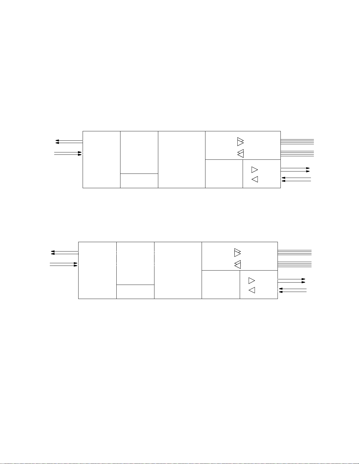
Maintenance Screen 47
Port Unloop
Pressing Enter takes down the specified loop from the currently selected port.
To Network
4
5
1
2
From Network
RJ48C
Test
Loops
Network Interf a c e
Loop status changes can be made only when the BERT function is not in the active
mode. The type of loop is chosen by toggling the spacebar and is executed by
pressing Enter. The normal operating mode and available loopback options for the
T1 network at the 3060-10 are shown in Figure 4-7 through Figure 4-11 and for the
DSU MP in Figure 4-11 and Table 4-4.
Normal Operation
Figure 4-7 depicts the unit’s normal operating mode.
Framer/Deframer Multiplexer Receivers /Drivers
From
NET
To
NET
Framer/Deframer
From
NET
To
NET
BERT Generator/
Detector
From
Ports
To
Ports
Figure 4-7 Normal Operation
Receivers/Drivers
DTE (DSX1)
(100' max.)
DTE (EIA530 or V.35)
RJ48C
DSX1, 1'-655'
to cross-connect
1
2
4
5
NET LLB
The network line loopback command loops data received from the network back
toward the network (Figure 4-8). Received data is passed through to the DTE ports.
To Network
4
5
1
2
From Network
RJ48C
Network Interface Framer/Deframer Multiplexer Receivers/Drivers
From
NET
To
NET
Framer/Deframer
From
NET
To
NET
Receivers /Drivers
DTE (DSX1)
NET
LLB
BERT Generator /
Detector
From
Ports
To
Ports
Figure 4-8 Network LLB
(100' max.)
EIA 530 or V.35
RJ48C
DSX1, 1'-655'
to cross-connect
1
2
4
5
Page 56
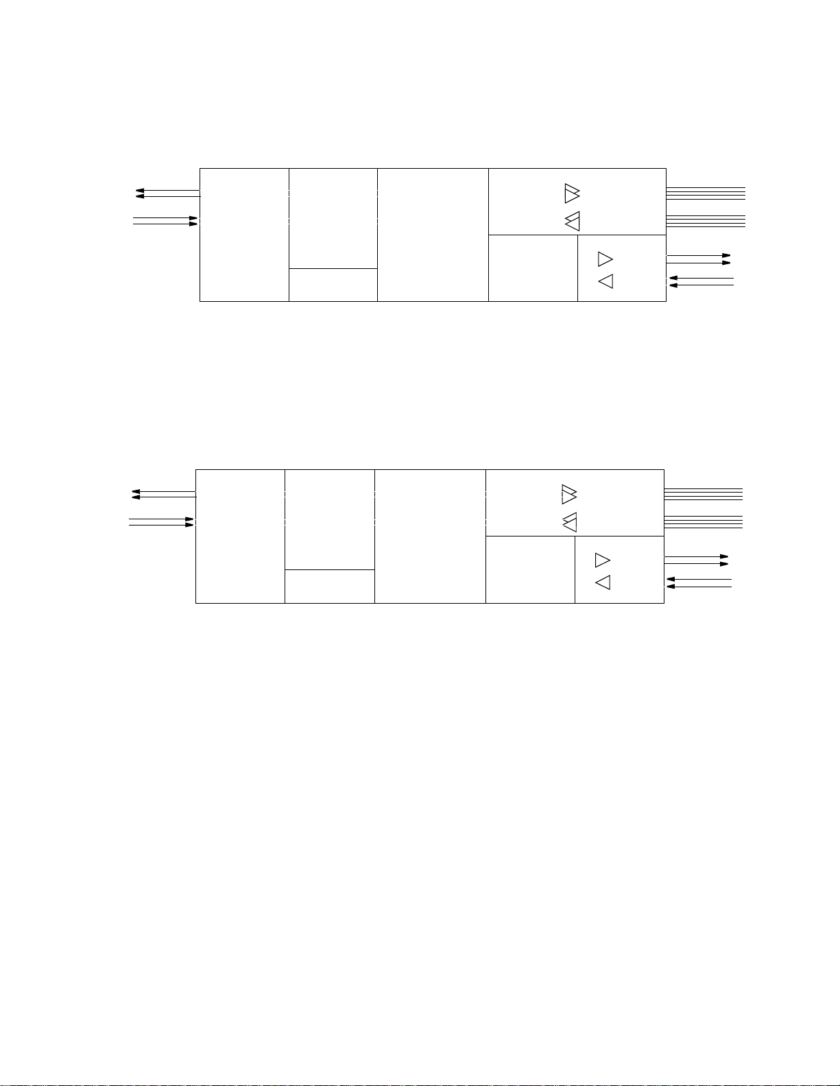
48 T
ERMINALOPERATION
NET PLB
The network payload loopback command loops the network data back toward the
network. Framing, CRC, and FDL are regenerated (Figure 4-9). Framed all ones
are passed to the DTE ports.
4
5
1
2
From Network
4
5
1
2
From Network
To Net wo r k
RJ48C
To Network
RJ48C
Network Interface Framer/Deframer Multiplexer Receivers/Drivers
From
NET
To
NET
Framer/Deframer
From
NET
To
NET
Receivers/Drivers
DTE (DSX1)
NET
PLB
BERT Generator /
Detector
All ones
to DTE
From
Ports
To
Ports
Figure 4-9 Network PLB
DTE MLB
The DTE maintenance loopback command loops all network data back toward the
DTE ports at the network interface. Data is passed through to the network. It is
advisable to set T1-NET Timing to INTERNAL rather than NETWORK when this
loop is enabled.
Network Interface Framer/Deframer Multiplexer Receivers/Drivers
From
NET
To
NET
Framer/ Deframer
From
NET
To
NET
Receivers/Drivers
DTE (DSX1)
DTE
MLB
BERT Generator/
Detector
Figure 4-10 DTE MLB
From
Ports
To
Ports
(100' m ax.)
EIA 530 or V.35
RJ48C
DSX1, 1'-655'
to cross-connect
(100' max.)
EIA530 or V.35
RJ48C
DSX1, 1'-655'
to cro ss-connect
1
2
4
5
1
2
4
5
FAR PLB
The far payload loopback command sends loop codes to the far-end unit to force it
into a network payload loopback mode.
Page 57
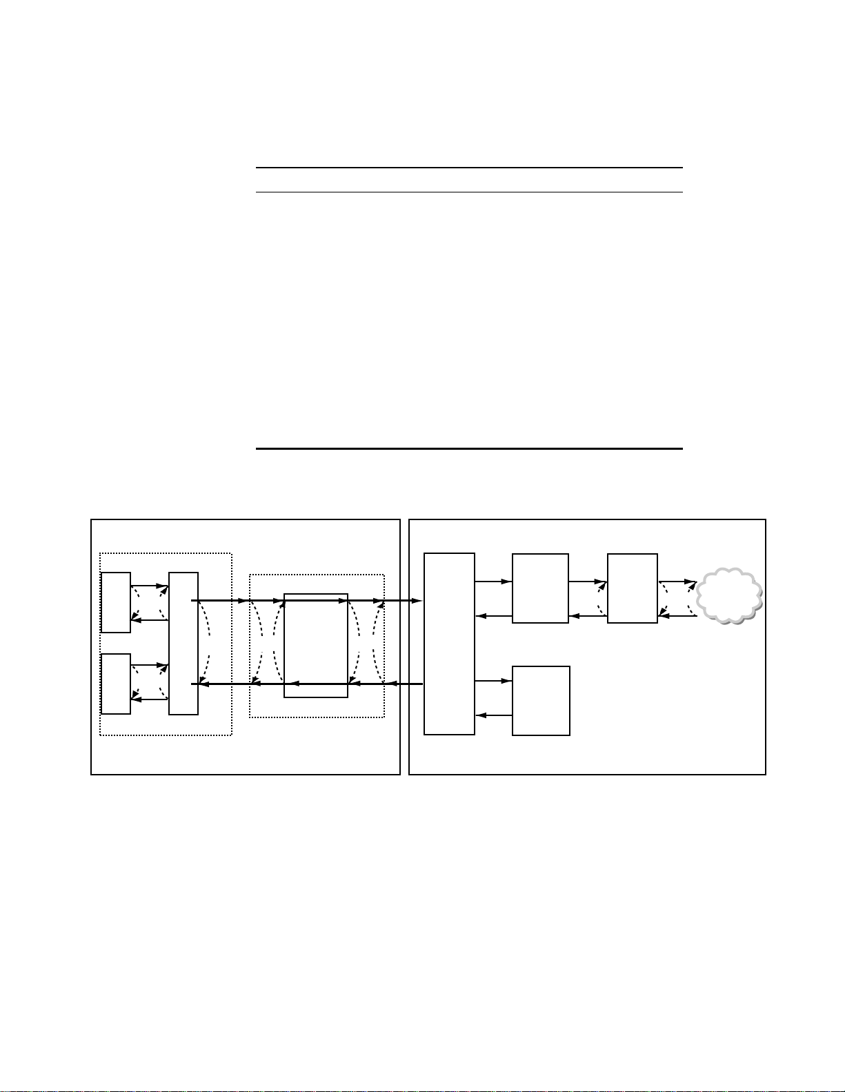
Maintenance Screen 49
FAR LLB
The far line loopback command sends loop codes to the far-end unit to force it into
a network line loopback mode.
Ta bl e 4 - 4 Test Loops for the 3060-10 and the DSU MP
Loop Type Unidirectional Loop Bidirectional Loops
DSU Line F, G
TDM C
DSU PLB D, E
DTE-A A1 & A2
DTE-B B1 & B2
V.54 Resp ond D, E
DDS I Data (ALB) D, G
(DDS II) DSU Latchin g D, G
DTE Local (LL pin) F, G
NET LLB H
DTE MLB I
NET PLB J
DTE
A
DTE
B
A1
A2
B1 B2
DSU MP T1
TDM
CD
Framing,
CRC, and
FDL
Control
DSU
E
G
F
Multiplexer
BERT
Pattern
Generator
and
Detector
Figure 4-11 Test Loops for the 3060 -10 and the DSU MP
Network
Interface
J I H
NETWORK
Page 58

50 T
ERMINALOPERATION
BERT BERT
All testing must be stopped before channels may be reallocated to an active port.
This field specifies the direction the BERT signa l is sent. If the direction is
changed from the front panel, the new choice is not updated on the terminal
interface until this screen is exited and then reentered. The choices are: IDLE, T1
NET, Channels 1-24, plus XY NET and XY DTE, where X = 3 through 6 and Y =
A through F. The choices are shown in Table 4-5.
Ta b l e 4-5 BERT Selections and Descriptions
Selections Description
T1 NET Tests the T1 network.
SLOT Tests the designated assigned slot, DSU, port, and direction.
Slots are selected in the left field at BERT and range at 3 through 6.
DSUs, ports, and directions are selected in the right field at BERT. DSU
ranges from 1 through 6; ports are A and B, and the directions are
network and DTE.
This selection does not appear if no channels are assigned to any DSU.
CHAN Tests a designated unassigned channel, beginning with the lowest. This
selection does not appear if all channels are assigned.
IDLE Tests all unassigned channels at once. This selection does not appear if all
channels are assigned.
Pattern
This field specifies the pattern to be transmitted during a test. Modifying this field
does not
QRSS
cause the pattern to be transmitted (refer to Start Test). The choices are
, 63, 511, 2047, 215, 220, 223,1:8, 3:24, ALT, and CLEAR. The
CLEAR
pattern passes the received data through the unit (alarm detection and reporting is
disabled while the test is active). 511 is the only choice for the DSU MP.
Test Length
This field defines the run- time of test pattern generation and error accumulation.
The choices are Continuous
, 15 min, 30 min, 60 min, 24 hour. C ontinuous is the
only choice for the DSU MP.
Start Test
Pressing Enter with the cursor on this field starts the se lected test pattern.
PROGRESS
TEST
appears once the test has started. To end the test, press Enter on
.
TEST IN
STOP
Reset Errors
Pressing Enter with the cursor on this field clears the test error results.
The following fields ar e for display only. They reflect the selected test parameters and
the results of these tests only.
Pattern Sync
Displays the current state of pattern sync during a test. If no test is in progress, NO
TEST is displayed. If a test is active, but the receiver is not in pattern sync, NO
SYNC is displaye d. If the r eceiver is in p attern sy nc, IN SY NC is displayed.
Page 59

Maintenance Screen 51
Elapse d Time
Displays the amount of time elapsed since a timed test began or, if completed, the
total test time.
Bit Errors
Displays the total number of bit errors detected since the test began or since error
statistics were cleared (up to 999,999).
Errored Seconds
Displays the number of asynchronous errored seconds that have been detected
since the test began o r since e rror stat istics w ere last cl eared. Thi s param eter
includes bit error seconds and sync loss seconds.
% EFS
This ra tio is derived fro m the nu mber of error-free sec onds divided by th e number
of seconds accumulated in Elapsed Time.
Line Fault
and
Loop Status
The following fields are for display only. They reflect the selected test parameters and
the results of these tests only.
NET / DTE Status
Displays the fault status of the network and T1 DTE. They a re indicators of current
fault conditions and do not indicate that alarm thresholds are exceeded. Status
indications are described in Table 4-3 on page 45.
Near Loops
Displays the loop status of the near element. If there are more near loops than fits
on one line, the field scrolls by pressing the spacebar.
Far Loops
Displays the loop status of the far element. If there are more far loops than fits on
one line, the field scrolls by pressing the spacebar.
Page 60

52 T
ERMINALOPERATION
Configuration Screens
Parameters
Line
The various Configuration screens allow viewing and setting configuration
parameters for the network elements. Only the installed options are available as
menu items.
To send a new configuration to the unit, the user must press Enter on one of the
fields or exit the screen. The underlined values are the factory default parameters
stored in ROM.
The Line Parameters screen (Figure 4-12) allows reviewing and setting line
paramete rs for the selected element on the T1 circui t.
3060 DSU x.xx/x.xx PRISM 3060 Date: MM/DD/YY
3060 DSU x.xx/x.xx TXPORT Prism 3060-10 Time: HH:MM:SS
---------------------------------LINE PARAMETERS--------------------------------
Element: [NEAR]
T1-NET Framing: [ESF ] Rem Comm Channel: ( 0)
T1-NET Line Code: [B8ZS]
T1-NET LBO: [0 dB ]
PRM Enable: [DISABLE ]
Zero Suppression: [ENABLE ]
T1-NET Timing: [ENABLE ]
Station Timing: [64k x ] ( 1)
4--4-4 -----4 -----4 --4-- Channel Allocation: 6--5-3 -----1 -----2 --4-- Signalling Enabled: ------ ------ ------ ------
------------------------------------Messages-----------------------------------Local Screen
igure 4-12 Line Parameters S creen
This screen has the follow ing fields, most of which have user-selectable options.
To send the new line configuration to the unit, either press Enter on one of the
fields, chang e the Elem ent sele ction, or ex it the s creen.
T1-NET Framing
Selects t he framing for th e T1 netwo rk. The choices are D4 and E SF
.
T1-NET Line Code
Sets the network side line coding. The choices are AMI and B8ZS
.
T1 - NET LBO
Sets the line build out for the network interfa ce. The choices are
dB
, and
-22.5 dB
.
0 dB, -7.5 dB, -15
PRM Enab le
Allows the T1.403 Performance Report Message, which is sent once a second, to
be turned on or off. The choices are ENABLE and DISABLE
.
Page 61

Configuration Screens 53
Zero Suppression
Determ ines whether ones den sity insertion is activated after 15 zeros (rath er than
175 zeros). The choices are ENABLE
and DISABLE.
T1 - NET Timing
Sets the timing source to synchronize the unit’s internal timing generators. In all
cases, slips are controlled to occur on frame boundaries at the network and/or
DSX1 ports when timing synchronization is lost.
NETWORK.
Timing is derived from the network recovered clock (most applications
use this selection).
STATION.
Timing is derived from a bipolar- or TTL-compatible clock supplied to
the unit at the rear panel STA CLK connector. When this mode is selected, the
timing rate must also be set from Station Timing.
INTERNAL.
SLOT, DSU, and PORT.
The unit’s internal frequency standard is used for all timing.
Timing is synchronized to the external terminal timing
clock supplied from the DTE and connected to the selected slot, DSU, and port.
Station Timing
Selects the input timing and only appears when Station is selected from the
T1 - NET Timing menu. The choices are N×56K, N×64K, and 1.544 MHz. A
number appears to the right of this field when N×56K or N ×64 K is selected to
indicate the rate multiplier. A value from 1 through 24 must be entered.
Page 62

54 T
ERMINALOPERATION
Channel Allocation
These lines indicates the network channel assignments with Channel 1 on the left
and Channel 24 on the right.
The top line identifies the slot number and the bottom line identifies the port
number. A plus (+) sign in the slot position indicates either a remote
communication link or the fill channels used for the alternate channel assignment
mode. When channels are assigned to a port in the ALTERNATE mode, each data
channel is follow ed by an idle channel not assignable for other ports and marked
with an X in the port position. Channels may also be assigned as CONTIGUOUS.
The T1 DTE port is identified with an asterisk (*) in the port position. The Remote
Comm Link is identified with an R in the port position. Refer to the following
example.
222222 2+2+2+ 333333 11111+
Channel Allocation: AAAAAA BXBXBX 123456 *****R
Signalling Enabl ed: ------ --- --- ------ -X- X--
Slot 2 has a dual V.35 T1 card.
Slot 2, Port A is assigned to network channels 1 to 6 (contiguous)
Slot 2, Port B is assigned to network channels 7 to 12 (alternating)
Slot 3 has a DSU MP card.
Slot 3, DSU 1 is assigned to network channel 13.
Slot 3, DSU 2 is assigned to network channel 14.
Slot 3, DSU 3 is assigned to network channel 15.
Slot 3, DSU 4 is assigned to network channel 16.
Slot 3, DSU 5 is assigned to network channel 17.
Slot 3, DSU 6 is assigned to network channel 18.
Network channels 19 to 23 are mapped through to the T1 DTE.
Network channel 24 is assigned to the remote communication link.
Signalling Enabled: shows which channel has robbed-bit signalling enabled.
Signalling Enabled
The signalling option allows selection of Clear Channel or Robbed Bit signalling
for each DS0. Each DS0 is set to the Clear Channel DISABLE mode. This setting
should not be changed for raw data channels. However, channels using Robbed Bit
signalling must be specified to enable proper handling of the signalling bits.
In the Signalling Enabled row at the bottom of the screen, an X indicates that
signalling is enabled for that channel.
Page 63

Configuration Screens 55
Alarm
Parameters
The Al arm Para mete rs scre en ( Figure 4-13) allows the user to review and set a larm
related t hreshold s for the selected e lement. These thr esholds ar e the minimum
acceptable performance levels. To modify the parameters, highlight the desired
statistic, type in the new value (any number from 0 to 900) and press Enter. If this
value is later surpass ed, an a larm indica tion app ears. A field set to 0 causes t he
element not to alarm on that statistic.
3060 DSU x.xx/x.xx PRISM 3060 Date: MM/DD/YY
No Far End Response TXPORT Prism 3060-10 Time: HH:MM:SS
----------------------------- ALARM CONFIGURATION -----------------------------
Element: [NEAR]
Errored Seconds (ES): ( 45) Remote Alarm Seconds (RAS): ( 0)
Severely Errored Seconds (SES): ( 5) AIS Seconds (AISS): ( 0)
Loss of Signal Seconds (LOSS): ( 5) Out of Frame Seconds (OOFS): ( 5)
Unavailable Seconds (UAS): ( 0) BPV Seconds (BPVS): ( 0)
( 0) Alarm Reset Timer (seconds): ( 30)
Figure 4-13 Alarm Configuration Screen
If alarm thresholds are edited from the front panel, the corresponding values are not
reflected on this screen until it is exited and then reentered.
Errored Seconds
A one-second period in which at least one logic error occurred.
Severely Errored Seconds
A one-second period in which at least 320 CRC errors or 1 OOF (out - of-frame)
occurred.
Loss of Signal Seconds
A one-second period in which the T1 received signal is interrupted.
Unavailable Seconds
A one-second period in which consecutive severely errored seconds cause an
unavailable state.
Remote Alarm Seconds
Generated by the terminal equipment when an improper signal is received from the
facility (or after receiving unframed all ones).
Page 64

56 T
ERMINALOPERATION
AIS Seconds
A one-second period in which all ones are received.
Out of Frame Seconds
A one-second period in which a frame sync loss occurred.
BPV Seconds
A one-second period in which at least one bipolar violation occurred.
Alarm Reset Timer
Determines the number of seconds after alarm conditions clear before indications
are r emove d
Page 65

Configuration Screens 57
Port
Par am ete rs
The Port Configuration screen (Figure 4-14) allows viewing and setting
configuration parameters for the DSU MP unit.
It is very important that the DTE ports at opposite ends of a link be configured
identically. For example, if port A of one DSU MP is configured for 19.2 kbps async,
then port A at the far end must also be configured for 19.2 kbps async. Neglecting to do this
may not only result in the inability to pass DTE traffic from end to end, but also misdirect
data intended for one por t (ex. A) to the opposite port (ex. B) at the far end. This data
swapping is a side effect of the rate-swapping feature and only occurs at DTE rates of 31.2
kbps (in TXP-I mode) and 38.4 kbps (in TXP-II mode) when units are configured improperly.
To send a new configuration to the unit, press Enter on one of the fields or exit the
screen. The underlined values are the factory default parameters stored in ROM.
This screen has the following fields, most of which have user-selectable options.
To send a new port configuration to the unit, either press Enter on one of the fields
or chang e the Por t #, cha nge the E lement s election, or exit the screen.
3060 DSU x.xx/x.xx PRISM 3060 Date: MM/DD/YY
3060 DSU x.xx/x.xx TXPORT Prism 3060-10 Time: HH:MM:SS
PRISM Port CONFIGURATION
Element: [ ]
422222 2+2+2+ 333333 11111+
Channel Allocation: 1AAAAA BXBXBX 123456 *****R
Signalling Enabled: ------ ------ ------ ------
Port #: [4-1A ]
Card Type: Hex DDS V.54 Loop : [Enable]
DDS Mode: [DDS-1 ]
DDS Rate: [56000 ] CTS Control: [Force True ]
Start Ch. #: ( 1) DSR Control: [Force True ]
Port Rate: [56000 ] DCD Control: [Force True ]
Port Format: [SYNC ] RTS Control: [Force True ]
Port Mode: [NON-TDM ] LL Detect: [Force True ]
Port Type: [V.35 ] RL Detect: [Force True ]
Tx Clock: [Internal ] Alarm On DTR Loss: [Disable]
------------------------------------Messages-----------------------------------Local Screen
igure 4-14 DSU MP Port Configuration Screen
Channel Allocation
A detailed description of this fie ld is de scribed in Channel Allocation on page 54.
Por t #
This parameter allows selecting the configuration of the slot (3 through 6), DSU (1
through 6), and the port.
The following parameters are for the displayed slot and port.
Card Type
This display-only field shows what kind of card is in a given slot.
Page 66

58 T
ERMINALOPERATION
DDS Mode
The unit can operate in one of four DDS modes on two types of DDS lines.
DDS-I.
DDS-I is a standard mode compliant with industry DDS-I standards
allowing the unit to be end - to -end compatible and interoperate with other vendor
DDS-compliant DSUs.
DDS-II.
DDS-II is a standard mode that can interoperate with other standard DDS-II
equipment.
TXP-I.
TXP-I is a proprietary mode for DDS-I lines that require a 41TDM or
PRISM 3060 -10 DSU MP unit at the other end of the line. This mode allows
two-port multiplexing with an in-band data link.
TXP-II .
TXP-II mode is a pr oprietary mode for DDS-II lines tha t require a 41TDM
or PRISM 3060 -10 DSU MP unit at the other end of the line. This mode allows
two-port multiplexing with an in-band data link.
DDS Rate
This field shows the network interface line rate as determined by the DDS mode
and is set as follows depending on the DDS Mode screen.
56K for DDS-I or T XP-I modes
64K for DDS-II or TXP-I I modes
Start C hannel #
The starting channel in the 24- channel DS1 bit stream must be selected in this field.
The unit then assigns the following channels automatically according to the bit rate and
the mode selected in DS0 Channel Assignment. The choices are 0 through 24.
Page 67

Configuration Screens 59
Por t R ate
The Port Rate is l ess than or equal to the DDS Rat e. The d efault values are 56K
for DDS I and 6 4K for DDS II. Tab le 4-6 shows t he Port R ates for various mod es
and format s.
Ta bl e 4 - 6 Data Rates
DDS Mode DTE Mode Format Data Rates
DDS-I NON-TDM sync 56K
DDS-II NON-TDM sync 64K
TXP-I NON-TDM async
sync
TDM async
sync
TXP-II NON-TDM async
sync
TDM async
sync
*
Only one port (A or B) can be set to the highest rate at any given time. For example, if Port A is set to
the highest rate, Port B can be set no higher than the next highest rate.
2.4K, 4.8K, 9.6K, 19.2K , 38.4K, 52K, 57.6K
2.4K, 4.8K, 9.6K, 19.2K , 38.4K, 52K
2.4K, 4.8K, 9.6K, 19.2K , 31.2K
2.4K, 4.8K, 9.6K, 19.2K , 31.2K
2.4K, 4.8K, 9.6K, 19.2K , 38.4K, 56K, 57.6K, 60K
2.4K, 4.8K, 9.6K, 19.2K , 38.4K, 56K, 60K
2.4K, 4.8K, 9.6K, 19.2K , 38.4K
2.4K, 4.8K, 9.6K, 19.2K , 38.4K
*
*
*
*
Port Format
This field show s the data format for the DTE port which can be synchronous
(SYNC
) or asynchronous (ASYNC). Asynchronous can be chosen only if one of
the TX P DDS m odes is selected.
Port Mode
The DSU MP interface can operate in either of two modes: NON-TDM
(standard)
and TDM (time division multiplex).
The DDS Mode must be set to either TXP-I or TXP-II to enable the TDM port mode.
NON-TDM (Port 1A, 2A, 3A, 4A, 5A, and 6A).
In the NON-TDM mode, DTE
interface B is disabled allowing DTE interface A to run at speeds up to the full
usable DDS line bandwidth as shown in Figure 4-15. This option is always
available.
DTE Port A T1 DS0DSU
Figure 4-15 NON-TDM Mode Functional Block Diagram
Page 68

60 T
ERMINALOPERATION
TDM (Port 1A, 1B, 2A, 2B, 3A, 3B, 4A, 4B, 5A, 5B, 6A, and 6B).
In TDM mode, both
DTE inte rfaces are ac tive and are m ultiplexed tog ether in to the sing le DD S
network path as show n in Figure 4-16. It allows access to configuration submenus
specific to DTE interface B.
DTE Po rt A
TDM T1 DS0DSU
DTE Po rt B
igure 4-16 TDM Mode Functional Block Diagram
Por t Typ e
For ports A and B, the Port Type field displays the installed DTE interface:
RS-232C
, V.35, or EIA-530.
For ports B, the interface is RS-232 only.
Tx Clock
Used to select the clock that the unit uses to sample the data transmitted from the
DTE. When set to
clock that is also supplied to the DTE as Transmit Clock. The
INTERNAL
, the data is sampled directly with the transmit data
EXTERNAL
option
uses the external clock supplied by the DTE.
V.54 Loop
Sele cting Ena ble
allows the unit to respond to in-band V.54 loop commands. If
Disable is selected, the unit ignores these commands.
CTS Control and DSR Control
Setting these fields to FORCE TRUE
or FORCE FALSE (in DSR mode only)
forces the port control lead output state. INTERNAL allows for normal operation.
DCD Control
Setting this fie ld to FORCE TRUE
forces the port control lead output state.
INTERNAL allows for normal operation. Far RTS is similar to INTERNAL except
that in far-end units the RTS lead becomes an additional qualifier. This selection is
only ava ilable when in TXP-I or TXP-II mode. When using Far RTS, ensure that
units at both ends are configured for Far RTS. If the unit at the far end is a
41TDM, its RTS parameter must be set to Normal; if it is set to Force On, Far
RTS does not work.
RTS Control
Request To Send is an inpu t to the uni t from the DT E. Clear To Send is an outp ut
from the un it to the DT E. The behav ior of RTS and CTS is se t as follows. In th e
External se tting, the unit rea cts to RTS from the DTE. When RTS is on, the uni t
transmits data norm ally and turns CTS on. When RTS is off, the un it transm its idle
code to the n etwor k and tu rns C TS off. In th e Forc e True settin g, the u nit ign ores th e
state of the RTS lead from the DTE and forces it on internally and forces CTS on.
Page 69

DDS Status Screen 61
LL Detect
This field allows selecting whether the DSU MP responds to the Local Loop lead
on the DTE connector. W hen the DTE device changes the state of this lead, the
DSU MP initiates a local loopback. The default setting is disable
.
RL Detect
This field allows selecting whether the DSU MP responds to the Remote Loop lead
on the DTE connector. W hen the DTE device changes the state of this lead, the
DSU MP initiates a remote loopback. The default setting is disable
.
Alarm on DTR Loss
Selecting Enable allows the unit to go into alarm on loss of DTR. The default
setting is Disable
.
DDS Status Screen
The DDS Near and Far Status screen (Figure 4-17) allows viewing the status of
every slot and DSU combination for the far- end equipment.
3060 DSU x.xx/x.xx P R I S M 3060 - 10 Date: MM/DD/YY
No Far End Response TXPORT Prism 3060-10 Time: HH:MM:SS
-----------------------------------DDS STATUS----------------------------------
NEAR 3-1: -------- 4-1: -------- 5-1: -------- 6-1: ------- 3-2: -------- 4-2: -------- 5-2: -------- 6-2: ------- 3-3: -------- 4-3: -------- 5-3: -------- 6-3: ------- 3-4: -------- 4-4: -------- 5-4: -------- 6-4: ------- 3-5: -------- 4-5: -------- 5-5: -------- 6-5: ------- 3-6: -------- 4-6: -------- 5-6: -------- 6-6: ------- REVs -------- REVs -------- REVs -------- REVs --------
FAR 3-1: -------- 4-1: -------- 5-1: -------- 6-1: ------- 3-2: -------- 4-2: -------- 5-2: -------- 6-2: ------- 3-3: -------- 4-3: -------- 5-3: -------- 6-3: ------- 3-4: -------- 4-4: -------- 5-4: -------- 6-4: ------- 3-5: -------- 4-5: -------- 5-5: -------- 6-5: ------- 3-6: -------- 4-6: -------- 5-6: -------- 6-6: --------
Key: a=Net Alarm c=Net Loop e=Download Needed g=Loop Detected
b=DTE Alarm d=DTE Loop f=Dial Backup Active h=Test Active
-------- ------------- ------------------Messages-------------- -----------------------NET ALARM Local Screen
Figure 4- 17 DDS Far Status Screen
Slot-DSU REVs
This field show s the revision number of the near DSU MP card in each slot. The
unit continously polls the card and reads this number.
a = Net Alarm
Alarm on the network. Alarms for the unit include ASC, FDL and LOS. Alarms
for the 41TDM include FDL, LOS, OOF, and OOS.
b = DTE Alarm
Alarm on the DTE. It is either a loss of DTR on DTE-A or DTE-B.
Page 70

62 T
ERMINALOPERATION
c = Net Loop
The unit is performing a network loop. On the near end this could be a Line, PLB, ALB
(for DDS-I), DSU latching (for DDS-II), V.54 respond, or DT E local (LL p in). If this
indicator occurs on the far side in a 41TDM, it is a Line, Local, Data, or V.54 loopback.
d = DTE Loop
The unit is pe rforming a DTE loop. This could be DTE-A, DTE-B, or TDM (DSU
MP only).
e = Download Needed
The far end (41TDM ) needs a download.
f = Dial Backup Active
The far end (41TDM) is in dial backup mode.
g = Loop Detected
This occurs only when the unit is in TXP-I or TXP-II mode. The unit detects that
it is receiving what it is transmitting so there is a loop somewhere: in the unit, on
the line, or on the far end.
Utilities Screen
h = Test Active
The unit is performing a BERT or a far DTE loop test.
The Utilities screen (Figure 4-18) handles the functions described in the following
paragraphs.
3060 DSU x.xx/x.xx PRISM 3060 Date: MM/DD/YY
No Far End Response TXPORT Prism 3060-10 Time: HH:MM:SS
------------------------------------ UTILITIES --------------------------------
Element: [NEAR]
Set Time: (12:34:25)
Set Date: (04/30/93)
Alarm Notification: [DIAL ]
Primary Phone#: (205-555-1212 )
Secondary Phone#: (205-532-8853 )
Element ID: (DSU 1230 )
New Password: (JohnDoe )
(MAINTENANCE RESET)
Figure 4- 18 Utilities Screen
Page 71

Utilitie s Screen 63
General
Functions
Set Time
The current time may be entered in this field using the 24- hour HH:MM:SS
format. Fo r example , 3:45 a.m. is entere d as
0345
and 3:45 PM is entered as
1545
Set Date
The current date may be entered in this field using the MM : DD : Y Y format. For
example, July 4, 1993 is entered as
The time and date can be set at the far end, but not displayed.
070493
.
New Password
Allows entry of a passwor d of up to 10 characters. An empty string (carriage
return only) may be entered to disable the password feature. After Enter is pressed,
the new password is activated and is no longer visible. Therefore, type carefully
when entering a new password and verify before pressing Enter. When the terminal
interface is exited and later reactivated, this password must be entered exactly to
gain access. If the wrong passwor d is entered, the following message appears:
Incorrect Password; Please Enter Again.
Do not exit the terminal interface program until the password procedure is fully understood.
If a passwor d has been specified, it must be typed exactly to reenter the program.
.
COA
Parameters
If the user programs a password and later forgets it, the password may be cleared
through the front panel maintenance reset (see Maintenance Reset on page 16).
The reset operation sets all parameters to the factory default settings and zeros all
performance registers. If the reset operation is not a satisfactory option, then call
TXPORT Customer Support for a one-time-use back door password (see Support
from TXPORT on page 65).
Maintenance Reset
Clear al l user-select able param eters, p erformanc e registers , passwords , and alarm s.
All alarm threshold parameters is reset to default values. The unit reloads start-up
configuration settings from the default parameters stored in ROM. Pressing Enter
on this field brings up a warning prompt asking whether or not to perform the reset
function.
The following fields pertain only to call on alarm functions.
Alarm N otificatio n
Controls the remote alarm reporting. The choices are
Disables alarm reporting.
OFF.
DIRECT.
Sends reports to a printer or terminal connected directly to the
supervisory port.
Sends reports through an attached AT command set compatible modem
DIAL.
connect ed to the S UPV serial port , which must dial out to a remote modem. The
message format is described in the Element ID fie ld.
Page 72

64 T
ERMINALOPERATION
DIAL NMS.
Sends reports through a modem to an 8100A Site Controller.
Primary Phone #, Secondary Phone #
ASCII strings for the primary and secondary call on alarm phone numbers used in
the
DIAL
and
DIAL NMS
modes. The strings must not include the ATDT-command
prefix.
The unit makes three attempts to connect using the primary number. If all three
attempts fail, the unit makes three attempts to connect using the secondary number
(if it is not blank). If the secondary number fails, the unit waits five minutes and
then attempts to communicate using the primary number again. When a conne ction
is detected, the unit outputs the notification message and disconnects.
Element ID
Allows the entry of an ASCII string (29 characters in length) which identifies the
unit to the device receiving the alarm notification messages.
Call on alarm messages are reported in the following format in the
DIRECT
Element ID HH:MM:SS MM/DD/YY CR LF
NET Alarms: alarms CR LF
DTE Alarms: alarms CR LF
modes only:
DIAL
or
where (
RAS, AIS, UAS, ERRS
Joesunit 17:24:55 08/04/93
NET Alarms: LOS AIS ERRS
DTE Alarms: LOS 2A 2B 3A 3B
The user-programmable
alarms
) is a string consisting of some or all of the identifiers
, or the wor d
Element ID
NONE
. The followin g is an exam ple:
string is transmitted first to allow the COA
LOS, OOF
,
function to send a message with a specific meaning to some host (such as a log on
message).
The ident ifier ERRS re present s an alarm that is caused by ES, S ES, and/or BPV
errors.
Page 73

A
C
USTOMER
TXPORT provides easy access to customer support information through a variety
of services. This section describes these services.
S
ERVICE
Support from Your Network Supplier
Support from TXPORT
Telephone To speak directly w ith a TXP ORT customer s ervice rep resentat ive, dial, toll fre e,
If assistance is required, contact your network supplier. Many suppliers are
authorized TXPORT service partners who are qualified to provide a variety of
services, including network planning, installation, hardware maintenance,
application training, and support services.
When you contact your network supplier for assistance, have the following
informat ion ready:
✦ Diagnostic error messages
✦ A list of system hardware and software, including revision levels
✦ Details about recent configuration changes, if applicable
If you are unable to receive support from your network supplier or want to contact
us directly, TXPORT offers worldwide customer support 24 hours a day, 7 days a
week by telephone, E-mail, and World Wide Web.
one of the following numbers or dial TXPORT’s local telephone number.
✦ Sales and Marketing: 888 - 4TXPORT
✦ Technical Support
800 -285-2755
:
✦ Local: 256 -772 -3770
E-mail You can request sales and marketing information or pose a technical support
question about your TXPORT product with direct e-mail access.
✦ Sales and Marketing: info@txport.com
✦ Technical Support: support@txport.com
World
Wide
Web
Access the latest networking information on TXPORT’s World Wide Web site by
entering our URL into your internet browser.
http://www.txport.com/
Page 74

66 C
HAPTER
USTOMER SERVICE
A: C
This service features information about TXPORT products, customer service,
technical support, latest news releases, and more.
Returning Products
If for any reason you must return your TXPORT product, it must be returned to
the factory, shipping prepaid and pack aged to the best comme rcial standard for
electronic equipment. TXPORT will pa y shipping charges for delivery on return.
You are responsible for mode and cost of shipment to TXPORT.
You must have a Return Material Authorization (RMA) number marked on the
shipping package. Products sent to TXPORT without RMA numbers will be
returned to the sender unopened, at the sender’s expense. A product sent directly to
TXPORT for repair must first be assigned a Return Materials Authorization
(RMA) number.
You may obtain an RMA number from customer service at 800- 926- 0085, ext.
2282. When calling TXPORT for an RMA, please have the following information
available.
✦ Model number and serial number for each unit.
✦ Reason for return and symptoms of problem.
✦ Warranty status (if known).
✦ Purchase order number to cover charges for out - of -warranty items.
✦ Name and telephone number of a person we can contact if we have questions
about the unit(s).
Ordering Numbers
✦ Mode of shipment required (second-day a ir is the normal mode of shipment for all
returned ma terial unless otherw ise specified).
Units being returned to TXPORT should be sent to the following address.
TXPORT
127 Jetplex Circle
Madison, Alabama 35758
The part number to order a TXPORT 3010 -400 DSU M P is F-3010 - 400 --1161.
The part number to order a TXPORT 3060 -10 is F-3060 -001--1311.
The DSU MP requires the PRISM 3060-10 to have software revision 2.64 or greater.
Contact TXPORT I nside Sales for a software upgrade, if needed.
Each PRISM 3060-10 unit is supplied with the following standard equipment:
✦ Attached 19-inch mounting brackets
✦ AC power supply cord
✦ PRISM 3060-10/DSU MP reference manual
The TXPORT 3010 - 400 is shipped from the factory with the following standard
equipment:
✦ 3010 -400 reference manual (p.n. 34-00252)
Page 75

Ordering Numbers 67
✦ two 120-pin D -subminiature to six DB-25 adapter cables (p.n. 7-3010- 266-010).
The equipment options shown in Table B-1 may be required for the installation and
operation of the PRISM equipment.
Table B-1 Optional Equipment
Part Number Description
NET Cables
9-1001-004-010 8-pin/RJ-48 to 8-pin/RJ-48 Interface Cable
9-1001-043-010 10 ft RJ-48 to RJ- 48 Null Cable
9-1001-051-1 T1 crossover kit, 1 ft
9-1001-006-1
9-1001-006-2
Sup ervis ory Ca bles
9-1001-027-1
9-1001-027-2
9-1001-028-1
9-1001-028-2
9-1001-029-2 DB-9 female to 6-pin mod (terminal to SUPV)
9-1001-048-1
9-1001-048-2
Miscellaneous
9-3060-028-1 Mounting brackets for 23-inch racks
8-pin mod to 15-pin D-type adapter, male
8-pin mod to 15-pin D-adapter, female
DB-25 male to 6-pin mod (modem to SUPV)
DB-25 female to 6-pin mod (modem to SUPV)
DB-25 male to 6-pin mod (terminal to SUPV)
DB-25 female to 6-pin mod (terminal to SUPV)
DB-25 male to two 6-pin mod (terminal to NMS)
DB-25 female to two 6-pin (terminal to NMS)
Page 76

68 C
HAPTER
USTOMER SERVICE
A: C
 Loading...