

Page 1
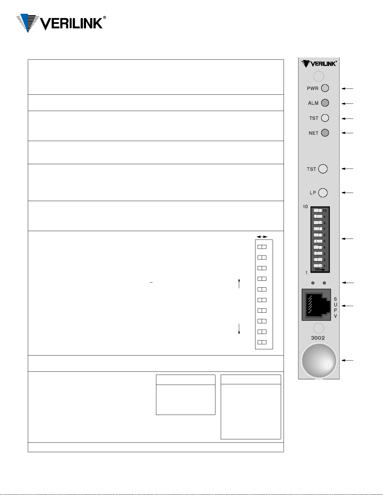
Front Panel Description
Left
Right
123456789
10
SUPV Rate
SUPV Rate
128
64
32
16
8
4
2
1
LSB MSBBinary values
0
0
0
0
0
0
0
0
Control/
Index
Indicator
Function/Description
PRISM 3002
Configuration Guide
45-00121
4.0
1PWR
This LED lights continuously when power is applied to the unit.
(green)
2ALM
(red)
3TST
(3-color)
This LED lights conti nuously when the unit is in an active alarm condition.
This LED blinks to show it has a duplicate NMS address detected by an 8100A.
Flashing Green: The unit is transmitting loop code.
Solid Green: BERT is on with no errors or the unit is in clear test.
Red: BERT is on and receiving errors.
Amber: The unit is looped.
4NET
(3-color)
Green: The unit is in f rame sync.
Amber: The unit is receiving a yellow alarm from the far end.
Red: The unit is out of frame sync and/or has loss of signal.
5 TST When this button is pushed once, the unit transmits five seconds of in-band LLB code out
to the network and pe rforms a T1 NET BERT. Indicator TST blinks green during
transmission of the loop code. If the TST button is pushed again, the unit transmits five
seconds of in-band loop down code and returns to normal operating mod e . The TST
indicator then turns off.
6 LP When this momentary push button is pushed once, the unit activates a line loopback,
looping the network receive data back to the network, and looping the dat a from the DTE
ports back to the DTE. The TST indicator is amber while the unit is looped. If pushed
again, the unit clears the loop and turns off the TST indicator.
7 10-position
DIP switch
Switches S1-1 through S1-8 set th e NMS a d dress for the network
manager port. W hen using the 3002 with an 8100A Site
Controller, each element must have a unique unit address (see
index item 2, ALM). The 8100A Site Controller can address up to
100 units (with addresses from 1 to 100). If the unit is not
connected to a site controller , the NMS unit addre ss should remain
at the factory default setting of 1
where Position 1 is Left and all
other positions are Right.
Switch positions S1-1 through S1-8 are used to create an 8-bit
binary code for an ad dress in the range of 1 to 253. Switch
position S1-1 is the least significant bit (LSB) and S1-8 is the
most significant bit (MSB). If a switch is Right, its value is 0. If
Left, its value is that shown on the left. The values are additive.
For example, to set a unit address to 5, positi on S1-3 (value is 4)
and position S1-1 (value is 1) would be set Left for a unit address
of 5 (4+1). All other positions would be set Right. If all the
switches are Right, the address is 1.
8 These small, recessed red LEDs indicate supervisory and network manager act ivity from
the 3002.
9 SUPV The supervisory port provides
direct terminal access for
control and gathering status and
facility performance data.
Tables showing the port rate
and pinout are given on the
right.
10 Extractor/cardlock
SUPV Port Rate S1-9 S1-10
1.2 kbps Left Left
2.4 kbps Right Left
9.6 kbps Right Right
19.2 kbps Left Right
SUPV Port Pinout Pin
Data Terminal Ready Out 1
Ready to Send Out 2
Frame Ground 3
Data Out 4
Data In 5
Signal Ground 6
Clear to Send In 7
Data Carrier Detect In 8
1
2
3
4
5
6
7
8
9
10
Front Panel
Page 2

Specifications
Network Interface
Line Rate: 1.544 Mbps (± 50 ppm)
Line Framing: D4 or ESF
Line Code: AMI or B8ZS
Input Signal: 0 to −27 dB ALBO
Connection: RJ-48C jack, 100 Ω (± 5%)
Output Signal: 3.0 V (±10%) base-peak
into 100 Ω with protection
Line Build Out: 0, −7.5, −15, −22.5 dB
attenuation
Transient Voltage: 1000 V protection,
fused input/output
Jitter Control: per TR62411 and T1.403
Timing Source: Internal, recovered line clock,
external DTE
Ones Density: B8ZS, N×56 bit stuffing, alternate
fill; complies with TR62411
Equipment Interface
DTE Ports: single port
Compatibility: Subminiature-D 26-pin, female
ITU V.35
Data Rate: Synchronous, Ν×56 kbps or
N×64 kbps (where N = 1 to 24)
Clocking: Internal, External, Oversample
Data Invert: May be enabled or disabled
Supervisory Port
Connection: 8-pin modular (RS-232)
Data Rates: 1. 2, 2.4, 9.6, and 19.2 kbps
Diagnostics
Performance: Monitoring per TR54016 and
T1.403
Network Loops: Line loopback, payload loopback,
Fractional Loop: Responds to in-band V.54
DTE Port Loops: Bidirectional loop toward DTE
BERT: Multiple test patterns toward
Alarms
Activation: Programmable thresholds
Reporting: Front panel LEDs, call out on
Power
DC: 48 VDC, 0.25 A, 12 W maximum,
Mechanical
Mounting: Horizontal rack
Dimensions: Width 0.69 inches (1.75 cm)
Weight: 0.66 pounds (0.30 kg)
Environmental
Operating Temp: 32° to 122°F (0° to 50°C)
Storage Temp:
Humidity: 95% maximum (non-condensing)
or maintenance loo pback in the
network direction
loop code
and Net
network or DTE port
alarm (COA), an d S N MP TRA P s
41 BTU maximum
Height 5.50 inches (14.0 cm )
Depth 11.0 inches (27.9 cm)
−4°
to 185°F (−20° to 85°C)
Standards
TR62411: December 1990
TR54016: September 1989
ANSI T1.403: 1989
TR54019A: April 1988
Industry Listings
FCC Compliance: Part 15 Class A, Subpart B,
Part 68
U.S. Safety: UL 1950, 3rd Edition
Canadian Safety: CSA C22.2 No. 950-95
Industry Canada: CS-03, Issue 8
Accessory Cables
Cable type Part Number
26-pin male-to-V.35 female 9-1001-113-010
26-pin male-to-V.35 male 9-1001-114-010
NET (Network)
NET Pinout
NET Interface Pin
Data In (T ip) 1
Data In (Ring) 2
Not used 3, 6
Data Out (Tip) 4
Data Out (Ring) 5
Chassis Ground 7, 8
V.35
Data Port
Rear Panel
Data Port Pinout
Signal
Frame Ground 1 1 A
Transmit Data 2, 14 2, 14 P, S
Receive Data 3, 16 3, 16 R, T
Request to Send 4 4, 19 C
Clear to Send 5 5, 13 D
Data Set Ready 6 6, 22 E
Signal Ground 7 7 B
Data Carrier Detect 8 8, 10 F
Transmit Clock 15, 12 15, 12 Y, AA
Receive Clock 17, 9 17, 9 V, X
Local Loopback 18 18 J
Data Term Ready 20 20, 23 H
Remote Loopback 21 21 BB
Terminal Timing 24, 11 24, 11 U, W
EIA-530
Backplane
EIA-530
DB-25
V.35
34-pin
127 Jetplex Circle
Madison, Alab a ma 35758
(800) 837-4546
www.verilink.com
Technical Assistance Center
(800) 285-2755
 Loading...