


PRISM 3001
FT1/T1
CSU/DSU


 ®
®
T R A N S P O R T
34-00186 February 1998
Copyright / Liability
© 1998 TxPORT, All rights reserved. No part of this publication may be reproduced, transmitted, transcribed, stored in a retrieval system, or translated into any language in any form by any means without the written permission of TxPORT.
Reorder # 34 -00186
5th Edition, February 1998
TxPORT shall not be liable for errors contained herein or for incidental or consequential damages in connection with the furnishing, performance, or use of this material. TxPORT reserves the right to revise this publication from time to time and make changes in content without obligation to notify any person of such revision changes.
Contents of this publication may be preliminary and/or may be changed at any time without notice and shall not be regarded as a warranty.
Documentation Disclaimer
TxPORT makes no representation or warranties of any kind whatsoever with respect to the contents hereof and specifically disclaims any implied warranties of merchantability or fitness for any particular purpose.
Table of Contents
1 General
Introduction . . . . . . . . . . . . . . . . . . . . . . . . . . . . . . . . . . 1-1
Features . . . . . . . . . . . . . . . . . . . . . . . . . . . . . . . . . 1-2
Specifications . . . . . . . . . . . . . . . . . . . . . . . . . . . . . . . . 1-2
Network Interface . . . . . . . . . . . . . . . . . . . . . . . . . 1-2
Equipment Interface . . . . . . . . . . . . . . . . . . . . . . . 1-3
User Interface . . . . . . . . . . . . . . . . . . . . . . . . . . . . 1-3
Diagnostics . . . . . . . . . . . . . . . . . . . . . . . . . . . . . . 1-3
Alarms . . . . . . . . . . . . . . . . . . . . . . . . . . . . . . . . . . 1-3
Power . . . . . . . . . . . . . . . . . . . . . . . . . . . . . . . . . . . 1-3
Mechanical . . . . . . . . . . . . . . . . . . . . . . . . . . . . . . 1-4
Environmental . . . . . . . . . . . . . . . . . . . . . . . . . . . . 1-4
Compatibility . . . . . . . . . . . . . . . . . . . . . . . . . . . . . 1-4
Industry Listings . . . . . . . . . . . . . . . . . . . . . . . . . . 1-4
FCC Requirements . . . . . . . . . . . . . . . . . . . . . . . . . . . . 1-4
Canadian Emissions Requirements . . . . . . . . . . . . . . . . 1-6
Warranty . . . . . . . . . . . . . . . . . . . . . . . . . . . . . . . . . . . . 1-6
Ordering Numbers . . . . . . . . . . . . . . . . . . . . . . . . . . . . 1-7
TxPORT Customer Service . . . . . . . . . . . . . . . . . . . . . 1-9
Product Technical Support . . . . . . . . . . . . . . . . . . 1-9
Acknowledgment . . . . . . . . . . . . . . . . . . . . . . . . . . . . . 1-9
2 Installation
Introduction . . . . . . . . . . . . . . . . . . . . . . . . . . . . . . . . . . 2-1
Safety Summary . . . . . . . . . . . . . . . . . . . . . . . . . . . . . . 2-1
Unpacking and Inspection . . . . . . . . . . . . . . . . . . . . . . 2-1
Supplied Materials . . . . . . . . . . . . . . . . . . . . . . . . . . . . 2-1
Mounting . . . . . . . . . . . . . . . . . . . . . . . . . . . . . . . . . . . . 2-2
Standalone Unit . . . . . . . . . . . . . . . . . . . . . . . . . . 2-2
Chassis Assembly . . . . . . . . . . . . . . . . . . . . . . . . . 2-2
Unit Configuration . . . . . . . . . . . . . . . . . . . . . . . . . . . . 2-2
Configuration Switch S4 . . . . . . . . . . . . . . . . . . . 2-3
Network Framing . . . . . . . . . . . . . . . . . . . . . 2-3
Network Coding . . . . . . . . . . . . . . . . . . . . . . . 2-4
Network LBO . . . . . . . . . . . . . . . . . . . . . . . . . 2-4
Bit Rates . . . . . . . . . . . . . . . . . . . . . . . . . . . . . 2-4
Clock Source . . . . . . . . . . . . . . . . . . . . . . . . . 2-4
Channel Assignment . . . . . . . . . . . . . . . . . . . 2-4
Address Switch S5 . . . . . . . . . . . . . . . . . . . . . . . . 2-5
Configuration Switch S6 . . . . . . . . . . . . . . . . . . . 2-5
NMS Bit Rate . . . . . . . . . . . . . . . . . . . . . . . . 2-6
Supervisory Port Bit Rate . . . . . . . . . . . . . . 2-6
Boot Mode . . . . . . . . . . . . . . . . . . . . . . . . . . . 2-6
Boot from switch settings . . . . . . . . . . . . 2-6
Boot from RAM . . . . . . . . . . . . . . . . . . . 2-6
Boot from manager . . . . . . . . . . . . . . . . . 2-6
Boot from ROM . . . . . . . . . . . . . . . . . . . 2-6
Rate Multiplier . . . . . . . . . . . . . . . . . . . . . . . . 2-7
S6 -8 . . . . . . . . . . . . . . . . . . . . . . . . . . . . . . . . 2-7
Rotary Switch S7 . . . . . . . . . . . . . . . . . . . . . . . . . . 2-7
T1 DTE Switch S8 . . . . . . . . . . . . . . . . . . . . . . . . 2-8
T1 DTE Line Framing . . . . . . . . . . . . . . . . . 2-8
T1 DTE Line Coding . . . . . . . . . . . . . . . . . . 2-8
T1 TE LBO . . . . . . . . . . . . . . . . . . . . . . . . . . 2-8
Supervisory Port Connection . . . . . . . . . . . . . . . . . . . . . 2-9
High-speed Port Connection . . . . . . . . . . . . . . . . . . . . . 2-9
NMS Connection . . . . . . . . . . . . . . . . . . . . . . . . . . . . . 2-10
SUPV . . . . . . . . . . . . . . . . . . . . . . . . . . . . . . . . . . 2-10
NMS IN/OUT . . . . . . . . . . . . . . . . . . . . . . . . . . . 2-10
NMS Split Cable . . . . . . . . . . . . . . . . . . . . . . . . . 2-11
NMS IN Only . . . . . . . . . . . . . . . . . . . . . . . . . . . . 2-11
Chassis Operation . . . . . . . . . . . . . . . . . . . . . . . . . 2-11
T1 DTE Port Connection . . . . . . . . . . . . . . . . . . . . . . 2-12
Network Connection . . . . . . . . . . . . . . . . . . . . . . . . . . 2-12
Disconnection Notice: . . . . . . . . . . . . . . . . . . . . . 2-13
NET/External Clock Connection . . . . . . . . . . . . . . . . 2-13
Alarm Connection . . . . . . . . . . . . . . . . . . . . . . . . . . . . 2-13
Standalone Unit . . . . . . . . . . . . . . . . . . . . . . . . . 2-13
Chassis Unit . . . . . . . . . . . . . . . . . . . . . . . . . . . . . 2-14
Power Connection . . . . . . . . . . . . . . . . . . . . . . . . . . . . 2-14
Standalone Unit . . . . . . . . . . . . . . . . . . . . . . . . . 2-14
Chassis Unit . . . . . . . . . . . . . . . . . . . . . . . . . . . . . 2-15
Redundant Power Source . . . . . . . . . . . . . . . . . . . 2-15
Single Power Source . . . . . . . . . . . . . . . . . . . . . . . 2-15
Dual Power Source . . . . . . . . . . . . . . . . . . . . . . . . 2-15
3 Operation
Introduction . . . . . . . . . . . . . . . . . . . . . . . . . . . . . . . . . . 3-1
Front Panel Controls and Indicators . . . . . . . . . . . . . . 3-1
General Status Indicators . . . . . . . . . . . . . . . . . . . . 3-1
Alarm Controls and Indicators . . . . . . . . . . . . . . . 3-2
Test Controls and Indicators . . . . . . . . . . . . . . . . . 3-2
Front Panel Testing . . . . . . . . . . . . . . . . . . . . . . . . . . . . 3-3
Test Switch . . . . . . . . . . . . . . . . . . . . . . . . . . . . . . . 3-3
Test Access Jacks . . . . . . . . . . . . . . . . . . . . . . . . . . 3-3
BERT Pattern Select . . . . . . . . . . . . . . . . . . . . . . . . 3-4
Supervisory Port . . . . . . . . . . . . . . . . . . . . . . . . . . 3-4
4 Terminal Operation
Introduction . . . . . . . . . . . . . . . . . . . . . . . . . . . . . . . . . . 4-1
System Description . . . . . . . . . . . . . . . . . . . . . . . . . . . . 4-1
Modem Compatibility . . . . . . . . . . . . . . . . . . . . . . . 4-1
Screen Components . . . . . . . . . . . . . . . . . . . . . . . . 4-2
Device Type and Revision . . . . . . . . . . . . . . . . . . . 4-2
Date/Time . . . . . . . . . . . . . . . . . . . . . . . . . . . . . . . . 4-2
Element ID/Unit Address . . . . . . . . . . . . . . . . . . . . 4-2
Menu Title . . . . . . . . . . . . . . . . . . . . . . . . . . . . . . . . 4-2
Messages . . . . . . . . . . . . . . . . . . . . . . . . . . . . . . . . . 4-2
iii
Interface Start Up . . . . . . . . . . . . . . . . . . . . . . . . . .4-3 Cursor Contros . . . . . . . . . . . . . . . . . . . . . . . . . . . .4-3 Field Types . . . . . . . . . . . . . . . . . . . . . . . . . . . . . . .4-3 Main Menu Screen . . . . . . . . . . . . . . . . . . . . . . . . . . . . .4-4 Alarms Screen . . . . . . . . . . . . . . . . . . . . . . . . . . . . . . . .4-5 Element . . . . . . . . . . . . . . . . . . . . . . . . . . . . . . . . . .4-5 NET/DTE Alarms . . . . . . . . . . . . . . . . . . . . . . . . . .4-6 (alarm status): . . . . . . . . . . . . . . . . . . . . . . . . . . . . .4-6 Power Loss Seconds . . . . . . . . . . . . . . . . . . . . . . . .4-6 Reset Alarm Registers . . . . . . . . . . . . . . . . . . . . . . .4-6 Performance Screens . . . . . . . . . . . . . . . . . . . . . . . . . . .4-7 Element . . . . . . . . . . . . . . . . . . . . . . . . . . . . . . . . . .4-7 Target . . . . . . . . . . . . . . . . . . . . . . . . . . . . . . . . . . . .4-7 USER NET . . . . . . . . . . . . . . . . . . . . . . . . . . . .4-7 USER DTE . . . . . . . . . . . . . . . . . . . . . . . . . . . .4-8 TELCO NET . . . . . . . . . . . . . . . . . . . . . . . . . .4-8 TELCO DTE . . . . . . . . . . . . . . . . . . . . . . . . . .4-8 Error Events . . . . . . . . . . . . . . . . . . . . . . . . . . . . . . .4-8 Reset Performance Registers . . . . . . . . . . . . . . . . . .4-8 Standard 24 Hour . . . . . . . . . . . . . . . . . . . . . . . . . . .4-8 Status . . . . . . . . . . . . . . . . . . . . . . . . . . . . . . . . . . . .4-8 Completed Days . . . . . . . . . . . . . . . . . . . . . . . . . . .4-8 Completed Intervals . . . . . . . . . . . . . . . . . . . . . . . . .4-8 24 Hr.% Error Free . . . . . . . . . . . . . . . . . . . . . . . . .4-8 (performance data) . . . . . . . . . . . . . . . . . . . . . . . . .4-9
Maintenance Screen . . . . . . . . . . . . . . . . . . . . . . . . . . .4-10 Clear Tests . . . . . . . . . . . . . . . . . . . . . . . . . . . . . . .4-10 Clear Alarms . . . . . . . . . . . . . . . . . . . . . . . . . . . . .4-10 Test Loops . . . . . . . . . . . . . . . . . . . . . . . . . . . . . .4-10 T1 Loop . . . . . . . . . . . . . . . . . . . . . . . . . . . . .4-10 T1 Unloop . . . . . . . . . . . . . . . . . . . . . . . . . . .4-11 Port Unloop . . . . . . . . . . . . . . . . . . . . . . . . . .4-13
Bit Error Rate Testing (BERT) . . . . . . . . . . . . . .4-13 BERT . . . . . . . . . . . . . . . . . . . . . . . . . . . . . . .4-13 Pattern . . . . . . . . . . . . . . . . . . . . . . . . . . . . . . .4-13 Test Length . . . . . . . . . . . . . . . . . . . . . . . . . . .4-13 Start Test . . . . . . . . . . . . . . . . . . . . . . . . . . . . .4-13 Reset Errors . . . . . . . . . . . . . . . . . . . . . . . . . .4-13 Pattern Sync . . . . . . . . . . . . . . . . . . . . . . . . . .4-13 Elapsed Time . . . . . . . . . . . . . . . . . . . . . . . . .4-13 Bit Errors . . . . . . . . . . . . . . . . . . . . . . . . . . . .4-13 Errored Seconds . . . . . . . . . . . . . . . . . . . . . . .4-14 % EFS . . . . . . . . . . . . . . . . . . . . . . . . . . . . . . .4-14
Line Fault and Loop Status . . . . . . . . . . . . . . . . .4-14 NET/DTE Status . . . . . . . . . . . . . . . . . . . . . .4-14 Near Loops . . . . . . . . . . . . . . . . . . . . . . . . . . .4-14 Far Loops . . . . . . . . . . . . . . . . . . . . . . . . . . . .4-14
Configuration Screens . . . . . . . . . . . . . . . . . . . . . . . . .4-14 Line Parameters . . . . . . . . . . . . . . . . . . . . . . . . . . .4-15 T1 - NET Framing . . . . . . . . . . . . . . . . . . . . . .4-15 T1 - NET Line Code . . . . . . . . . . . . . . . . . . . .4-15 T1 - NET LBO . . . . . . . . . . . . . . . . . . . . . . . . .4-15 PRM Enable . . . . . . . . . . . . . . . . . . . . . . . . . .4-15 Zero Suppression . . . . . . . . . . . . . . . . . . . . . .4-15 T1 - NET Timing . . . . . . . . . . . . . . . . . . . . . . .4-15
INTERNAL . . . . . . . . . . . . . . . . . . . . . . 4-15
T1 DTE . . . . . . . . . . . . . . . . . . . . . . . . . 4-15
PORT 1 . . . . . . . . . . . . . . . . . . . . . . . . . . 4-15
NETWORK . . . . . . . . . . . . . . . . . . . . . . 4-16
STATION . . . . . . . . . . . . . . . . . . . . . . . . 4-16
Station Timing . . . . . . . . . . . . . . . . . . . . . . . . 4-16
Remote Comm Channel . . . . . . . . . . . . . . . . 4-16
T1 -DTE Framing . . . . . . . . . . . . . . . . . . . . . 4-16
T1 -DTE Line Code . . . . . . . . . . . . . . . . . . . . 4-16
T1 -DTE DSX Level . . . . . . . . . . . . . . . . . . . 4-16
D/I Start Channel . . . . . . . . . . . . . . . . . . . . . 4-16
# of Channels . . . . . . . . . . . . . . . . . . . . . . . . . 4-17
Channel Allocation . . . . . . . . . . . . . . . . . . . . 4-17
Alarm Parameters . . . . . . . . . . . . . . . . . . . . . . . . . 4-17
Errored Seconds . . . . . . . . . . . . . . . . . . . . . . 4-17
Severely Errored Seconds . . . . . . . . . . . . . . . 4-17
Loss of Signal Seconds . . . . . . . . . . . . . . . . . 4-17
Unavailable Seconds . . . . . . . . . . . . . . . . . . . 4-17
DTE LOS/LOF Seconds . . . . . . . . . . . . . . . . 4-18
Remote Alarm Seconds . . . . . . . . . . . . . . . . . 4-18
AIS Seconds . . . . . . . . . . . . . . . . . . . . . . . . . 4-18
Out of Frame Seconds . . . . . . . . . . . . . . . . . . 4-18
BPV Seconds . . . . . . . . . . . . . . . . . . . . . . . . . 4-18
Alarm Reset Timer . . . . . . . . . . . . . . . . . . . . 4-18
Port Parameters . . . . . . . . . . . . . . . . . . . . . . . . . . . 4-19
Channel Allocation . . . . . . . . . . . . . . . . . . . . 4-19
Port # . . . . . . . . . . . . . . . . . . . . . . . . . . . . . . . 4-19
Rate Multiplier . . . . . . . . . . . . . . . . . . . . . . . 4-19
DS0 Channel Assignment . . . . . . . . . . . . . . . 4-19
Start Channel # . . . . . . . . . . . . . . . . . . . . . . . 4-19
Port Rate . . . . . . . . . . . . . . . . . . . . . . . . . . . . 4-20
# of Channels . . . . . . . . . . . . . . . . . . . . . . . . . 4-20
Transmit Clock . . . . . . . . . . . . . . . . . . . . . . . 4-20
V.54 Loop . . . . . . . . . . . . . . . . . . . . . . . . . . . 4-20
Invert Data . . . . . . . . . . . . . . . . . . . . . . . . . . . 4-20
CTS,DSR, and DCD Control . . . . . . . . . . . . 4-20
Utilities Screen . . . . . . . . . . . . . . . . . . . . . . . . . . . . . . . 4-21
Set Time . . . . . . . . . . . . . . . . . . . . . . . . . . . . . . . . 4-21
Set Date . . . . . . . . . . . . . . . . . . . . . . . . . . . . . . . . . 4-21
Alarm Notification . . . . . . . . . . . . . . . . . . . . . . . . 4-21
OFF . . . . . . . . . . . . . . . . . . . . . . . . . . . . . . . . 4-21
DIRECT . . . . . . . . . . . . . . . . . . . . . . . . . . . . . 4-21
DIAL . . . . . . . . . . . . . . . . . . . . . . . . . . . . . . . 4-21
DIAL NMS . . . . . . . . . . . . . . . . . . . . . . . . . . 4-21
Primary Phone#, Secondary Phone# . . . . . . . . . . 4-21
Element ID . . . . . . . . . . . . . . . . . . . . . . . . . . . . . . 4-22
New Password . . . . . . . . . . . . . . . . . . . . . . . . . . . 4-22
Maintenance Reset . . . . . . . . . . . . . . . . . . . . . . . . 4-22
iv
1 GENERAL
Introduction
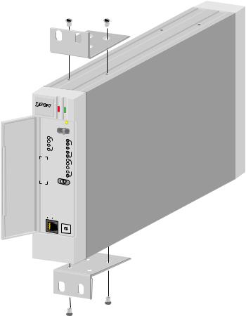
The TxPORT PRISM 3001 (Figure 1-1) is a modular, single port, fractional T1 CSU/DSU. The unit allows connection of high-speed digital data to a T1 facility. V.35or EIA530compatible high-speed port interfaces are available which support port rates from 56 kbps to 1.536 Mbps. The interface to the T1 network is made through an integral ESF CSU which provides full performance monitoring of the T1 span and is compliant with T1.403, TR62411, and TR54016.
|
® |
|
ESF |
3001 |
|
CSU/DSU |
||
|
|
|
ACO |
|
|
ACO SW |
|
|
TD |
V.35 |
|
|
|
BV/CR/FE |
|
|
RD |
D |
|
|
LOS/OOF |
|
||
RTS |
T |
|
|
E |
|
N |
|
DTR |
|
AIS |
E |
|
|
REM ALM |
T |
|
|
LOC ALM |
|
|
|
LLB |
|
|
|
PLB |
T |
|
|
FLB |
|
|
|
S |
|
|
|
TST |
T |
|
|
|
|
|
|
ERR |
|
|
|
FAR |
LOC |
|
|
|
|
S |
PAT |
|
SEL |
U |
|
5 |
|
P |
4 |
6 |
|
V |
3 |
|
7 |
2 |
|
8 |
|
|
1 |
0 |
|
|
|
9 |
Figure 1-1 PRISM 3001 Stand-alone
The unit is available with a second DSX1 level T1 interface to support drop and insert applications. Network bandwidth may be allocated as needed between the high-speed data port and the T1 DTE port, allowing the integration of data and voice traffic across a single T1 facility.
The TxPORT PRISM 3001 provides the powerful feature set of the multiport TxPORT PRISM 3000 in one of the most compact packages in the industry. The 3001 module can be installed in either a single unit housing or in the 1051 -2 nest mount chassis which holds up to twelve units. Power supplies are available to meet the requirements of small to large installations, including full redundancy.
1-2 GENERAL
The unit may be controlled through a VT100 terminal or a computer with ANSI terminal emulation software. If used with the EM8000 Element Manager or 8100A Site Controller, the entire T1 network can be monitored and controlled from a central location.
LED indicators are provided on the front panel of the unit to alert local personnel of alarm conditions, loop and test status, and DTE port activity. A test switch allows local and remote loops to be activated as well as BERT tests. Although all configuration parameters are software selectable from the terminal interface or the network manager, configuration switches are provided on the unit to allow operation without the use of a management interface.
Features
Stand-alone housing or chassis nest mounting
Integral full function D4/ESF CSU
Multiple loopback functions including BERT test patterns and in-band fractional loops
Selectable facility ALBO levels and DTE DSX levels
Flash memory allowing field upgrades of firmware
Selectable alarms, programmable alarm parameters and monitoring, and isolated alarm relay contacts
High-speed data port supporting both internal and external clocking
Thirty day storage of T1 line performance information
Optional EM8000 Element Manager and 8100A Site Controller
Specifications
Network |
Line Rate: |
1.544 Mbps, ± 50 ppm |
Interface |
Line Framing: |
D4 or ESF |
|
||
|
Line Code: |
AMI or B8ZS |
|
Input Signal: |
DS1, 0 to -27 dB ALBO |
|
Connection: |
RJ-48C modular jack (100 Ω, ± 5%) or terminal block |
|
Output Signal: |
DS1, 3.0 V (±10%) base-peak into 100 Ω with protection |
|
Line Build Out: |
0, -7.5, -15, and -22.5 dB attenuation |
|
Line Protection: |
1000 V lightning, fused input and output |
|
Jitter Control: |
per TR62411 and T1.403 |
|
Pulse Density: |
15 or 175 zeros |
|
Timing Source: |
Internal, recovered line clock, station clock, external DTE |
Equipment
Interface
User
Interface
Diagnostics
Alarms
Power
|
|
|
Specifications |
1-3 |
T1 DTE port: |
optional |
|
|
|
Line Rate: |
1.544 Mbps, ±50 ppm |
|
||
Line Framing: |
D4 or ESF |
|
|
|
Line Code: |
AMI or B8ZS |
|
||
Input Signal: |
DSX1 to -6 dB |
|
||
Connection: |
RJ-48C modular jack (100 Ω, ± 5%) |
|
||
Output Signal: |
Selectable DSX1 level from 0 to 655 feet in six |
|
||
|
increments |
|
|
|
high-speed data |
EIA-530 (RS-422), female DB-25 |
|
||
port compatibility: |
ITU V.35, |
female DB-25, and female |
|
|
|
34-pin through adapter cable |
|
||
Data Rate: |
Synchronous, N× 56 or N× 64 kbps (N = 1 to 24) |
|
||
Clocking: |
Internal |
or |
external |
|
Data Invert: |
Enable |
or |
disable |
|
Supervisory port: |
RS-232 6-pin modular connector, 1200 to 19200 baud |
|
||
Element Manager |
|
|
|
|
Site Controller: |
RS-232 6-pin modular connector, 1200 to 19200 baud (In |
|
||
|
and Out) |
|
|
|
Performance: |
TR54016 and T1.403 monitoring |
|
||
T1 Interface Loops: |
Line loopback or payload loopback |
|
||
Fractional Loop: |
high-speed bidirectional port loop responds to in-band V.54 |
|||
|
loop code |
|
|
|
T1 DTE Loops: |
Loop toward DTE or network |
|
||
BERT: |
Multiple test patterns toward network or DTE ports |
|
||
Activation: |
Programmable thresholds |
|
||
Reporting: |
Front panel LEDs, COA, NO/NC contacts, the EM8000 |
|
||
|
Element Manager, and 8100A Site Controller |
|
||
Contact Ratings: |
UL 0.3 A at 110 VAC |
|
||
|
1.0 A at 30 VDC |
|
||
Connection: |
Terminal block |
|
||
DC Power: |
-48 VDC (±10%), 165 mA max, 8 watts, 27 BTU maximum |
|||
Connection: |
Terminal block |
|
||

1-4 |
GENERAL |
|
|
|
Mechanical Stand-alone: |
Mounting: |
desktop, wall, horizontal or vertical rack, and |
|
|
|
vertical nest mount |
|
|
Dimensions: |
1.75" (4.45 cm) wide, 7" (17.78 cm) high, |
|
|
|
10.5" (26.67 cm) deep |
|
|
Weight: |
3 pounds, 7 ounces (1.56 kg) |
|
Chassis: |
Mounting: |
19" or 23" rack |
|
|
Dimensions: |
19" (48.3 cm) wide, 7" (17.8 cm) high, |
|
|
|
10.5" (26.7 cm) deep |
|
|
Weight: |
3 pounds, 7 ounces (1.56 kg) |
Environmental |
Operating Temp: |
0° to 50°C (32° to 122°F) |
|
|
Storage Temp: |
-20° to 85°C (-4° to 185°F) |
|
|
Humidity: |
95% max (non-condensing) |
|
Compatibility |
TR62411: |
December, 1990 |
|
|
TR54016: |
September, 1989 |
|
|
TR54019A: |
April, 1988 |
|
|
T1.403: |
1989 |
|
Industry |
FCC Compliance: |
Part 15 Subpart B, Class A, Part 68 |
|
Listings |
US Safety: |
UL 1459, 2nd Edition |
|
|
|||
|
Canadian Safety: |
CSA C222, No. 225-M90 |
|
|
Industry Canada: |
CS-03 |
|
FCC |
! |
WARNING: Changes or modifications to this unit not expressly approved by the |
|
Requirements |
party responsible for compliance could void the user’s authority to operate the |
||
equipment. |
|
||
This device complies with Part 15 of the FCC rules. Operation is subject to the following two conditions:
1This device may not cause harmful interference.
2This device must accept any interference received, including interference that may cause undesired operation.
FCC Requirements |
1-5 |
This equipment has been tested and found to comply with the limits for a Class A digital device, pursuant to Part 15 of FCC Rules. These limits are designed to provide reasonable protection against harmful interference when the equipment is operated in a commercial environment. This equipment generates, uses, and can radiate radio frequency energy and if not installed and used in accordance with the instruction manual, may cause harmful interference to radio communications. Operation of this equipment in a residential area is likely to cause harmful interference. The user will be required to correct the interference at his own expense.
Shielded cables must be used with this unit to ensure compliance with the Class A FCC limits.
Notice to Users of 1.544 Mbps Service: The following instructions are provided to ensure compliance with FCC Rules, Part 68:
1All direct connections to T1 lines must be made using standard plugs and jacks.
2Before connecting your unit, you must inform the local telephone company of the following information:
Port ID: |
P/N/12 - 00635 |
REN/SOC (Service Order Code): |
6.0 N |
FIC (Facility Interface Code): |
04DU9-BN |
|
04DU9-DN |
|
04DU9-IKN |
|
04DU9-ISN |
USOC jack: |
RJ-48C |
3If the unit appears to be malfunctioning, it should be disconnected from the telephone lines until you learn whether the source of trouble is your equipment or the telephone line. If your equipment needs repair, it should not be reconnected until it is repaired.
4The unit has been designed to prevent harm to the T1 network. If the telephone company finds that the equipment is exceeding tolerable parameters, they can temporarily disconnect service. In this case, the telephone company will give you advance notice, if possible.
5Under FCC rules, no customer is authorized to repair this equipment. This restriction applies regardless of whether the equipment is in or out of warranty.
6If the telephone company alters their equipment in a manner that will affect the use of this device, they must give you advance warning so that you can have the opportunity for uninterrupted service. You will be advised of your right to file a complaint with the FCC.
7The attached affidavit must be completed by the installer.
8In the event of equipment malfunction, all repairs should be performed by our company or an authorized agent. It is the responsibility of users requiring service to report the need for service to our company or to one of our authorized agents.
1-6 GENERAL
Canadian
Emissions
Requirements
This digital apparatus does not exceed the Class A limits for radio noise emissions from digital apparatus set out in the Radio Interference Regulations of the Canadian Department of Communications.
End users should use existing 48 VDC battery sources or a CSA-certified power supply.
|
Le présent appareil numérique n’émet pas de bruits radioélectriques dépassant les |
|
limites applicables aux appareils numériques (de la class A) prescrites dans le |
|
Règlement sur le brouillage radioélectrique édicté par le ministère des |
|
Communications du Canada. |
Warranty |
TxPORT warrants each unit against defects in material and workmanship for a |
|
period of five years from the date the unit was shipped to the customer. If the unit |
|
malfunctions at any time during the warranty period, TxPORT will repair, or at |
|
TxPORT’s option, replace the unit free of charge. |
|
The remedies listed herein are the user’s sole and exclusive remedies. TxPORT |
|
shall not be liable for any indirect, direct, incidental or consequential damages. |
|
The owner must return the unit to the factory, shipping prepaid and packaged to |
|
the best commercial standard for electronic equipment. TxPORT will pay shipping |
|
charges for delivery on return. The customer is responsible for mode and cost of |
|
shipment to TxPORT. This warranty does not apply if the unit has been damaged |
|
by accident, misuse or as a result of service or modification by other than TxPORT |
|
personnel. |
|
When returning the unit for warranty work, a Return Material Authorization |
|
(RMA) number must be obtained from customer service at the address/phone |
|
number given below. When calling TxPORT to obtain a Return Material |
|
Authorization number or to arrange service, please have the following information |
|
available: |
Model number(s) and serial number(s) for the unit(s).
Reason for return and symptoms of problem.
Warranty status (if known).
Purchase order number to cover charges for out-of-warranty items.
Name and phone number of person we can contact if we have questions about the unit(s).
Mode of shipment required (second day air is the normal mode of shipment for all returned material unless otherwise specified).
As soon as TxPORT has the above information, the RMA that must accompany the item(s) returned can be issued.
Ordering Numbers |
1-7 |
Ordering |
This unit is shipped from the factory with the PRISM 3001 reference manual. The |
Numbers |
part numbers for the standalone unit and the modular chassis unit are shown in |
|
Table 1-1. |
|
Table 1-1 PRISM 3001 Options |
Part Number |
Description |
|
|
F-3001-1A0-1B0DE |
PRISM 3001 stand-alone unit |
A |
Test jacks |
0 |
No test jacks |
5 |
Bantam jacks |
B Special option
1Standard unit
2RS-423 station clock input
3Bidirectional loop
DDTE port option 2 V.35
3 EIA-530
EDSX T1 DTE option 0 Not installed
1 DSX T1 DTE port
F-3001-1A1-1B0DE0 PRISM 3001 module (chassis)
A Test jacks
0 No test jacks
5 Bantam jacks
B Special option
1Standard unit
2RS-423 station clock input
3Bidirectional loop
DDTE port option 2 V.35
3 EIA-530
EDSX T1 DTE option 0 Not installed
1 DSX T1 DTE port

1-8 GENERAL
The following optional accessories may also be needed for the installation and operation of the TxPORT PRISM 3001.
Table 1-2 Optional Equipment
Part Number |
Description |
|
NET / T1 DTE Cables |
||
9 |
-1001-004 |
8-pin mod to 8-pin mod (4 twisted pairs) |
9 |
-1001-051-1 |
T1 cross-over kit, 1 ft |
9 |
-1001-006-1 |
8-pin mod to 15-pin D-type adapter, male |
9 |
-1001-006-2 |
8-pin mod to 15-pin D-adapter, female |
Supervisory Cables |
|
|
9 |
-1001-027-1 |
DB-25 male to 6-pin RJ-11 (modem to SUPV) |
9 |
-1001-027-2 |
DB-25 female to 6-pin RJ-11 (modem to SUPV) |
9 |
-1001-028-1 |
DB-25 male to 6-pin RJ-11 (terminal to SUPV) |
9 |
-1001-028-2 |
DB-25 female to 6-pin RJ-11 (terminal to SUPV) |
9 |
-1001-029-2 |
DB-9 female to 6 -pin RJ-11 (terminal to SUPV) |
9 |
-1001-048-1 |
DB-25 male to two 6-pin RJ-11 (term. to NMS) |
9 |
-1001-048-2 |
DB-25 female to 6-pin RJ-11 (term. to NMS) |
V.35 Cables |
|
|
9 |
-1001-001 |
V.35 male to male null cable |
9 |
-1001-311 |
V.35 male to male cable |
9 |
-1001-312 |
V.35 male to female cable |
EIA-530 Cables |
|
|
9 |
-1001-511N |
EIA-530 male to male null cable |
9 |
-1001-511 |
EIA-530 male to male cable |
9 |
-1001-512 |
EIA-530 male to female cable |
RS-449 Cables |
|
|
9 |
-1564A -037-1 |
RS-449 male to EIA-530 male |
9 |
-1564A -037-2 |
RS-449 male to EIA-530 female |
9 |
-1564A -038-1 |
RS-449 to EIA-530 null cable, male to male |
Chassis Mount Kits |
|
|
F -1051-000--112 |
1051 -2 chassis (RJ-48C) |
|
9 |
-2000-001--1 |
19" single unit rack mount adapter |
9 |
-2000-001--2 |
19" dual rack mount adapter |
9 |
-2000-002-- |
23" single unit rack mount adapter |
9 |
-2000-002--2 |
23" dual rack mount adapter |
F -1040-000--111 |
Power supply shelf with single/redundant -48 |
|
F -1040-000--112 |
VDC, 2 A supply |
|
F -1200-000--11 |
1200 power supply with redundant |
|
|
|
-48 VDC, 5 A with fuse panel |
30-00087 |
0.2 amp wall mount power supply |
|
Miscellaneous |
|
|
9 |
-8000-001-1 |
EM8000 with manual on 3½ inch disk (DOS and |
9 |
-8000-001-2 |
UNIX version, respectively) |
9 |
-1001-052-010 |
DB-25 male to V.35 male |
9 |
-1001-053-010 |
DB-25 male to V.35 female |
9 |
-1001-511-010 |
DB-25 male to DB-25 male, 1:1 |
9 |
-1001-522-010 |
DB-25 female to DB-25 female, 1:1 |
|
|
|
TxPORT Customer Service |
1-9 |
TxPORT |
TxPORT |
|
|
Customer |
127 Jetplex Circle |
|
|
Service |
Madison, Alabama 35758 |
|
|
|
Telephone Numbers: |
800 |
-926 -0085 or |
|
|
205 |
-772 -3770 |
|
Sales/Administration FAX: |
205 -772 -3388 |
|
|
Manufacturing FAX: |
205 |
-772 -8280 |
|
Customer Service Returns: |
800 |
-926 -0085, ext. 227 |
Product |
Normal Hours (8 a.m. to 5 p.m. Central Time, Monday through Friday) |
||
Technical |
|
800 |
-285 -2755 or |
Support |
|
205 |
-772 -3770, ext. 255 |
|
Emergency (nights/weekends/holidays) |
||
|
Telephone: |
800 |
-285 -2755 |
|
E-Mail (Internet Address): |
support@txport.com |
|
Acknowledgment |
The software used in the SNMP function of this product contains material derived |
||
|
from the following source: |
|
|
Copyright © 1989 by the Regents of the University of California. All rights reserved.
Redistributions in binary form must reproduce the above copyright notice, this list of conditions, and the following disclaimer in the documentation and/or other materials provided with the distribution. All advertising materials mentioning features or use of this software must display the following acknowledgment:
This product includes software developed by the University of California, Berkeley and its contributors.
Neither the name of the University nor the names of its contributors may be used to endorse or promote products derived from this software without specific prior written permission.
This software is provided by the regents and contributors ‘as is’ and any express or implied warranties, including, but not limited to, the implied warranties of merchantability and fitness for a particular purpose are disclaimed. In no event shall the regents or contributors be liable for any direct, indirect, incidental, special, exemplary, or consequential damages (including, but not limited to, procurement of substitute goods or services; loss of use, data, or profits; or business interruption) however caused and on any theory of liability, whether in contract, strict liability, or tort (including negligence or otherwise) arising in any way out of the use of this software, even if advised of the possibility of such damage.
1-10 GENERAL

2
Introduction
Safety
Summary
Unpacking and Inspection
Supplied
Materials
INSTALLATION
This chapter contains information and instructions required to prepare the TxPORT PRISM 3001 for use. Included are initial inspection procedures, mounting instructions, configuration guidelines, connection instructions, and powering information.
Throughout this manual, all factory default settings are shown underlined.
This manual contains information and warnings which must be followed to ensure safe operation and to retain the equipment in a safe condition.
The WARNING sign denotes a hazard to the operator. It calls attention to a
!procedure or practice which, if not correctly performed or adhered to, could result in injury or loss of life. Do not proceed beyond a WARNING sign until the indicated
conditions are fully understood and met.
Follow proper ESD (electrostatic discharge) procedures while handling the circuit boards.
This unit is carefully packaged to prevent damage in shipment. Upon receipt, inspect the shipping container for damage. If the shipping container or cushioning material is damaged, notify the carrier immediately and make a notation on the delivery receipt that the container was damaged (if possible, obtain the signature and name of the person making delivery). Retain the packaging material until the contents of the shipment have been checked for completeness and the instrument has been checked both mechanically and electrically.
If the contents of the shipment are incomplete or, if there is mechanical damage or defect, notify TxPORT. If the shipping container is also damaged, or the cushioning material shows signs of stress, notify the carrier of the damage as well as TxPORT. Keep the shipping materials for carrier’s inspection. TxPORT will arrange for repair or replacement without waiting for claim settlement.
The PRISM 3001 is shipped from the factory with the PRISM 3001 reference manual.
The following additional materials may be required for the installation and operation of the PRISM 3001.
-48 VDC power source
Network and DTE interface cables
20-gauge stranded wire (or similar) for DC power and alarm connection
2-2 |
INSTALLATION |
|
|
|
For specific applications, additional cables and adapters may be required. The |
|
|
interface requirements of any application may be met by using the appropriate |
|
|
cable. Contact TxPORT for any needed assistance in cable selection. |
Mounting |
The 3001 is a modular unit that plugs into either a single unit housing or into a |
|
|
|
chassis that holds up to 12 units. Single units are designed for stand-alone desktop |
|
|
use, wall mounting, or chassis mounting (in either a vertical or horizontal |
|
|
orientation). The 3001 uses an interchangeable front panel to accommodate the |
|
|
chassis card cage. |
|
Stand-alone |
To access the circuit boards and configuration switches, perform the following |
|
Unit |
procedure. Observe proper electrostatic device handling procedures while holding |
|
|
the circuit boards. |
1Open the front panel access door and remove it by gently bending the plastic from the middle using both hands.
2Pull the two side strips of plastic from the middle outwards until the four stops are clear of the front panel.
3Pull the cover off the front panel.
4Remove the two screws and pull the front panel and circuit boards out of the housing.
The stand -alone unit may be used in a chassis installation with the following modifications.
1Remove the housing as described above and then remove the four screws holding the front panel to the circuit boards.
2Replace the stand -alone front panel with a module type front panel. The unit can now slide into one of the 12 slots in the chassis.
Chassis |
Up to twelve PRISM 3001 units may be inserted into a chassis and the chassis |
Assembly |
may be installed into a 19or 23-inch rack using four screws. Connections are |
|
made from the rear of the chassis (refer to the illustrations on page 2-9). |
Unit |
The PRISM 3001 can be software configured in the same manner as the multiport |
Configuration |
PRISM 3000 by using a terminal connection to either the front panel Supervisory |
|
access port or the rear panel NMS IN port. The TxPORT EM8000 Element |
|
Manager and 8100A Site Controller may also be used to configure the unit by |
|
using the same ports. The terminal interface, element manager, and site controller |
|
provide a broader set of capabilities than by using the configuration switches. |
|
The 3001 provides non-volatile memory retention of unit configuration in the |
|
event of power failure. This feature allows the unit to automatically restore normal |
|
service following a power loss. Note, however, that when the unit is stored without |
|
power for an extended period, the battery may drain and some parameters may |
|
become corrupted. |

Unit Configuration |
2-3 |
Alarm
4 |
5 |
6 |
|
|
|
|
|
|
|
|
|
|
|
|
|
|
|
|
|
|
|
|
|
|
|
|
3 |
|
7 |
|
|
|
|
|
|
|
|
|
|
|
|
|
|
|
|
|
|
|
|
|
|
|
|
|
8 |
|
|
|
|
|
|
|
|
|
|
|
|
|
|
|
|
|
|
|
|
|
|
|
|
|
2 |
|
|
|
|
|
|
|
|
|
|
|
|
|
|
|
|
|
|
|
|
|
|
|
|
|
|
1 |
0 |
9 |
1 |
2 |
3 |
4 |
5 |
6 |
7 |
8 |
1 |
2 |
3 |
4 |
5 |
6 |
7 |
8 |
1 |
2 |
3 |
4 |
5 |
6 |
7 |
8 |
|
|
|
|
S7 |
S6 |
S5 |
S4 |
Figure 2-1 Top-edge View of PRISM 3001
Therefore, when the unit is first received for installation or if power has not been applied for an extended period of time, the configuration should be verified using either the terminal interface, element manager, or site controller. The battery becomes fully charged after power has been applied for 160 hours.
Hardware switches on the side of the circuit boards provide the means to configure most simple applications. These configuration switches are described in the following paragraphs. When power is applied to the unit, the front panel indicators flash for approximately 10 seconds as the unit executes a self -test function. If an ambiguous configuration has been programmed, the front panel indicators continue to flash after the self-test is completed. The configuration must then be reviewed to correct the error.
The unit is hardware configured using three DIP switches, a rotary switch, and two jumpers. All are located on the top edge of the circuit boards (refer to Figure 2-1 above). The front panel rotary switch selects BERT patterns and is described in the Operations chapter. The numbering system used for each switch position is as follows: Position 2 of Switch S4 is referred to as Switch S4 -2, and so on.
Before installation, verify each configuration switch setting. A removable configuration guide is included in the rear of this manual to record option selections for reference.
Configuration Switch S4 is used to set the configuration parameters listed in the following Switch S4 paragraphs.
Up |
Network Framing |
|||
|
|
|
|
|
|
|
|
|
|
|
|
|
|
|
|
|
|
|
|
|
|
|
|
|
Dn |
1 |
Figure 2-2
Network Coding |
Network LBO |
Network LBO |
Bit Rates |
Clock Source |
Clock Source |
Channel Assignment |
||||||||||||||
|
|
|
|
|
|
|
|
|
|
|
|
|
|
|
|
|
|
|
|
|
|
|
|
|
|
|
|
|
|
|
|
|
|
|
|
|
|
|
|
|
|
|
|
|
|
|
|
|
|
|
|
|
|
|
|
|
|
|
|
|
|
|
2 |
3 |
4 |
5 |
6 |
7 |
8 |
Switch S4 |
|
|
|
|
|
|
Network Framing
Position S4-1 is used to match the unit to the framing of the network line.
Down: ESF |
Up: D4 |

2-4 INSTALLATION
Network Coding
Position S4-2 sets the network line coding to AMI or B8ZS.
Down: AMI |
Up: B8ZS |
Network LBO
Positions S4 -3 and S4-4 set the line build out signal level of the transmit data (TXD) from the unit to the network. The output level is factory set at 0 dB. It may be attenuated by -7.5 dB, -15 dB, or -22.5 dB if operating conditions require that it be changed. The telco should provide the proper setting to the user. If unsure of the exact setting, then leave it at the default value. The values are listed in the following table.
Table 2-1 Network Line Build Out
S4-3 S4-4 |
Network LBO |
|
|
|
|
Down |
Down |
0 dB |
Up |
Down |
-7.5 dB |
Down |
Up |
-15.0 dB |
Up |
Up |
-22.5 dB |
|
|
|
Bit Rates
Position S4-5 works in conjunction with rotary switch S7 to set bit rate configurations. Refer to Rotary Switch S7 on page 2-7 for further information. The missing rates are N × 56 and N ×64, where N=15,17, 21, and 23. All 24 rate configurations can be programmed through software control by using the NMS or SUPV ports.
Clock Source
Positions S4 -6 and S4-7 determine the source of unit clocking. The most common timing source for most CSU/DSU applications is to derive timing from the network. The 3001 may also be optioned to time from an internal standard, from the T1 DTE, or from the high-speed data interface as shown in Table 2-2.
Table 2-2 Timing Source
S4-6 |
S4-7 |
Timing Source |
|
|
|
Down |
Down |
Internal |
Up |
Down |
Network |
Down |
Up |
T1 DTE |
Up |
Up |
high-speed port |
|
|
|
Channel Assignment
Position S4-8 selects the channel assignment mode for network T1 DS0s that carry data to the high-speed port. Contiguous assignment assigns the channels as a block beginning at channel one. For example, if the high-speed port data rate is to be 256 kbps (as defined by rotary switch S7 in on page 2-7), the unit would assign network channels 1 through 4 to the high-speed port.
 Loading...