

Page 1

TRANSPORT
3001
CDS/DSU
ACO SW
21
20
19
18
Described
TD
RD
RTS
DTR
FRM
NET
V.35
BV/CR/FE
D
T
E
REM ALM
FAR
on back
MON
17
S
U
16
P
V
PRISM 3001
Front Panel
Pattern Select
0 QRSS
11 in 8
23 in 24
3 2047
20
-1
42
5Clear
663
7 511
8 Factory use only
9Flash
SUPV Pinout
1 Control Out
2 Signal Ground
3 Data Out
4 Data In
5 Signal Ground
6 Control In
STATUS
ACO
LOS/OOF
AIS
LOC ALM
LLB
PLB
FLB
TST
ERR
PAT SEL
4
3
2
®
PRISM 3001
45-00058
4.0
Configuration Guide (Stand-alone Version)
Front Panel Description
Item Function
Status:
The green LED li ghts when the unit is power ed and operating normally. The red LE D lights if an alarm
exceeding thresholds is de tected or for other unit failure.
ACO:
This yellow LED li ghts if the A C O (al arm cut off) switch is place d in the left ON posi ti on. It indic at es tha t
the alarm relay cont acts are disabled.
ACO SW:
This ACO (alarm cut off) switc h controls the alarm relay circuitry. If the switch is plac ed in the left
ON position, this circuitry is deactivated.
BV/CR/ FE:
This LED lights one second for ea ch occurrence of bipolar violations, cyclic redundancy c heck
errors, or frame bit errors.
LOS/OOF:
This LED blinks with a loss of signal (LOS) from the network. It lights constantly when an out of
frame (OOF) condition is detected.
AIS:
This alarm indication signal LED lights if an unframed all ones condition is detected from the network.
REM ALM:
LOC ALM:
LLB:
This LED lights constantly when a remote (yellow) alarm signal is received.
This LED lights w h en a local alarm exc eeding alarm th res holds exists.
This LED lights contin uously when the network interface is in a lin e l oopback. It flashes when the T1
DTE interface is in a line loopback .
PLB:
This LED lights continuously when the network interface is in a payload loopback.
FLB:
This LED is active for port loops. It lig hts continuously when th e unit is in a fractional (high-speed port) loop.
TST :
This LED lights continuously during a far or local test. It flas hes while loop codes are transmitted at the
LOC
1
1
2
2
3
3
4
4
5
N
E
T
T
S
T
5
6
7
6
8
7
9
8
10
9
11
12
10
13
11
14
12
start of a far test and while unloo p codes are transmitted at the end of a far test . Wh en FAR is selected, the uni t
sends five seconds of in-band loop code, then use s the test pat te rn set by the PAT SEL switch. When moved back
to center, the unit sends five seconds of loop down code. When LOC is selected, the unit performs a network line
TO
NET
MON
loop. When moved back to center, the lo cal loopback is removed.
ERR:
13
14
15
This LED lights when BERT pattern errors are detected.
T est Switch:
PAT SEL:
This switch is used for local testing with the test pattern selected by the rotary switch Pattern Select.
This pattern select switch determines the BERT pattern sent by the unit when the test sw itch is in the
FAR or LOC position. Refer to the table a bove.
SUPV:
16
This 6- pin jack provides direct terminal access for controlling the unit and gathering status and fac il it y
performance data. Refer to the pinout tabl e in the lower left corner.
Activity:
5
6
7
8
9
1
0
17
15
18
19
20
21
DTR:
RTS:
RD:
TD:
These small, reces s ed LED s ind icate SUPV and NMS port acti v i ty.
This green LED lights when the data terminal ready signal is active.
This green LED lights when the request to send signal is active.
This green LED ligh ts duri ng a mark condition on the high-speed receive data line .
This green LED lights during a mark condition on t he high-speed transmit data line.
Specifications
Network Interface
Line Rate: 1.544 Mbps, ± 50 ppm
Line Framing: D4 or ESF
Line Code: AMI or B8ZS
Input Signal: DS1, 0 to -27 dB ALBO
Connection: RJ-48C modular jack
Output Signal: DS1, 3.0 V (±10%)
Line Build Out: 0, -7.5, -15, and
Line Protection: 1000 V lightning,
Jitter Control: per TR62411 and T1.403
Pulse Density: 15 or 175 zeros
Timing Source: Internal, recovered line
Equipment
T1 DTE port optional
Line Rate: 1.544 Mbps, ± 50 ppm
Line Framing: D4 or ESF
Line Code: AMI or B8ZS
Input Signal: DSX1 to -6 dB
Connection: RJ-48C modular jack
Output Signal: Selectable DSX1 level
(100 Ω, ± 5%) or
terminal block
base to peak into 100 Ω
with protection
-22.5 dB attenuation
fused input and output
clock, station clock,
external DTE
Interface
(100 Ω, ±5%)
from 0 to 655 feet in
six increments
High-speed
data port
compatibility: EIA-530 (RS-422),
Data Rate: Synchronous, N×56 or
Clocking: Internal or external
Data Invert: Enable or disable
User
Interface
Supervisory port: RS-232 6-pin
Element Manager ,
Site Controller: RS-232 6-pin modular
Diagnostics
Monitoring: per TR54016 and T1.403
T1 Interface
Loops: Line loopback or
Fractional Loop: High-speed
T1 DTE Loops: Loop toward DTE or
BERT: Multiple test patterns
female DB-25
ITU V.35, female
DB-25 female, 34-pin
through adapter cable
N×64 kbps (N = 1 to 24)
modular connector,
1200 to 19200 baud
connector, 1200 to
19200 baud (In and Out)
payload loopback
bidirectional port loop
responds to in-band
V.54 loop code
network
toward network or
DTE ports
Alarms
Activation: Programmable
Reporting: Front panel LEDs,
Contact Ra t ing s: UL 0.3 A at 110 VA C
Power
DC Power: -48 VDC (± 10%),
Connection: Terminal block
Mechanical
Mounting: desktop, wall, horizontal
Dimensions: 1.72"W, 6.8" H, 10.5" D
Weight: 3 pounds, 7 ounces
Compatibility
TR62411: December, 1990
TR54016: September, 1989
TR54019A: April, 1988
T1.403: 1989
Industry Listings
FCC Compliance: Part 15 Subpart B,
US Safety: UL 1459, 2nd Edition
Canadian Safety: CSA C222, No. 225-M90
Industry Canada: CS-03
thresholds
COA, NO/NC
contacts, TxPORT
EM8000 and 8100A
1.0 A at 30 VDC
165 mA max,
8 watts, 27 BTU max
or vertical rack, vertical
nest mount
Class A, Part 68
Page 2
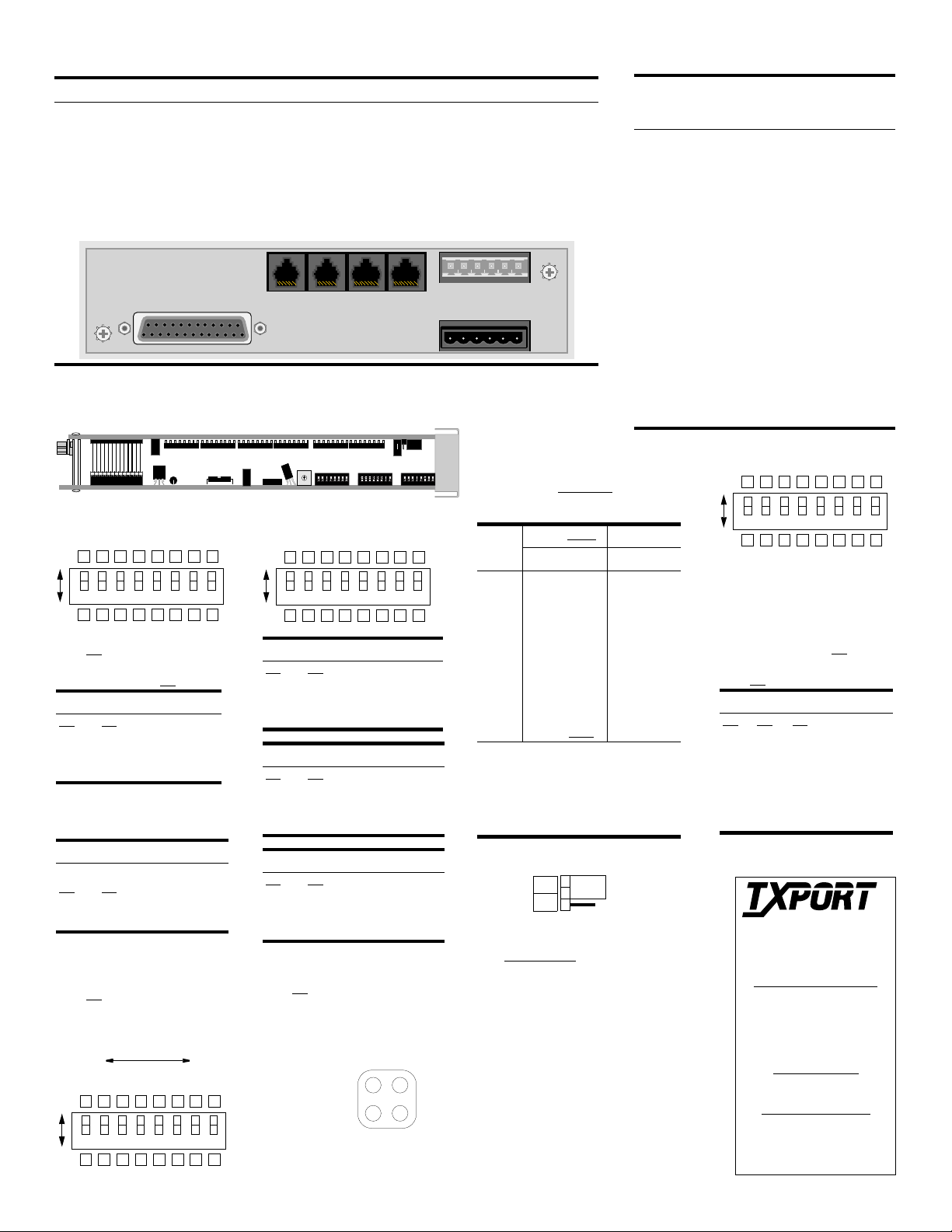
1051-2 Chassis Rear Panel Pinouts
D
U
D
U
D
U
Pin T1 D/I T1 NET NMS IN NMS OUT Alarm /Power Net/Ext. Clk
1 Data Out Data In Not Used Not Used 48 V Return Net In (Tip)
2 Data Out Data In Signal Groun d Signal Ground Sig nal Ground Net In (Ring)
3 Not Used Not Used Data Out Data Out -48 VDC Net Out (Tip)
4 Data In Data Out Data In Not Used Frame Ground Net Out (Ring)
5 Data In Data Out Signal Groun d Signal Ground Al arm Contact Station Clk (Ring)
6 Not Used Not Used Not Used Not Used Alarm Common Station Clk (Tip)
7, 8 Chassis Ground Chassis Ground Not Applicable Not Applicable Not Applicable Not Applicable
High-speed DTE Pinout
DB-25
Common
25-pin
Name
A/B
1 Frame Ground 1 1 A
7 Signal Ground 7 19 B
2/14 Transmit Data 2/14 4/22 P/S
3/16 Receive Data 3/16 6/24 R/T
4/19 Request to
Send
EIA-530
25-pin
A/B
RS-449
37-pin
A/B
4/19 7/25 C
V.35
34-pin
A/B
5/13 Clear to Send 5/13 9/27 D
6/22 Data Set
6/22 11/29 E
Ready
1
6
1
8
1
8
DTE
14
1
PORT
6
25
NMS IN
13
T1 D/I
NMS OUT
1
1
NETWORK
NTWK/EXT CLK
ALARM/POWER
48 VDC
61
20/23 Data Term
Ready
8/10 Data Carrier
Detect
15/12 Transmit
20/23 12/30 H
8/10 13/31 F
15/12 5/23 Y/AA
Clock
Top-edge View of the 3001
Alarm
For reference, all DIP
switches are provided with
17/9 Receive Clock 17/9 8/26 V/X
24/11 Terminal
24/11 17/35 U/W
Timing
upper and lower boxes to
Switch S4
p
8654321
n
S4-1:Network Framing
: ESF Up: D4
Dn
S4-2:Network Coding
Dn: AMI Up
S4-3 S4-4 Network LBO
Dn
Dn 0 dB
Up Dn -7.5 dB
Dn Up -15.0 dB
Up Up -22.5 dB
S4-5:Channel Assignment - Used to
select DS0 channels (used with Switch
S7). See Table S7 Bit Rates (kbps).
S4-6 S4-7 Timing Source
Dn Dn Internal Settings
Up Dn Network
Dn Up T1 DTE
Up Up High-speed port
S4- 8: Channel Assignment - Used to
select channel assignment mode (used
with Switch S7).
: Contiguous Up: Alternate
Dn
7
: B8ZS
5
6
4
7
3
8
2
9
1
1 2 3 4 5 6 7 8 1 2 3 4 5 6 7 8 1 2 3 4 5 6 7 8
0
S5 S4S6S7
Switch S6
p
8654321
n
S6 - 1 S6-2 NMS Port Rate
Dn 19200 bps
Dn
Up Dn 9600 bps
Dn Up 2400 bps
Up Up 1200 bps
S6 -3 S6 -4 SUPV Port Rate
Dn 19200 bps
Dn
Up Dn 9600 bps
Dn Up 2400 bps
Up Up 1200 bps
S6 -5 S6 -6 Power-up Mode
Dn Switch Settings
Dn
Up Dn RAM
Dn Up Network Manager
Up Up ROM
S6-7:Used to set the multiplier with
Switch S7.
: ×64 kbps Up: ×56 kbps
Dn
S6-8:Not used.
7
check the particular user
selection. Factory default settings are shown underlined
.
S7 Bit Rates (kbps)
w/S4-5 down
Switch
S7
×56 × 64 ×56 × 64
0 56 64 168 192
1 112 128 280 320
2 224 256 392 448
3 336 384 448 512
4 560 640 504 576
5 672 768 616 704
6 1008 1152 728 832
7 1120 1280 784 896
8 1232 1408 896 1024
9 1344 1536
20 of the 24 possible bit rat e co nfigurations are available through Switc h S7
(and Switch S4). The missing rates are
N×56 and N×64, where N=15, 17, 21,
and 23. All 24 rate configurations are
available through software control .
w/S4-5 up
1064 1216
Alarm Relay
NO
NC
This 3-pin header straps the ACO alarm
contact. Positio n jumper over pins 1 and
2 for normally open
alarm) or over pins 2 and 3 for normally
closed operation (open s on al arm).
1
2
3
operation (closes on
Switch S8 (T1 DTE)
p
8654321
n
If equipped, this board is located on
the opposite side of the circuit board
shown in Figure Top-edge View of the
3001.
S8- 1: Used to set the line framing.
Dn: ESF Up
S8- 2: Used to set the line coding.
: AMI Up: B8ZS
Dn
S8 -3 S8-4 S8-5 DTE LBO
Dn Dn 0 - 110 ft
Dn
Up Dn Dn 110 - 220 ft
Dn Up Dn 220 - 330 ft
Up Up Dn 330 - 440 ft
Dn Dn Up 440 - 550 ft
Up Dn Up 550 - 655 ft
Dn Up Up >655 ft
S8- 6, S8-7, and S8-8: Not used.
TRANSPORT
127 Jetplex Circle
Madison, Ala ba m a 35758
Sales and Marketing
800-926-0085
7
:D4
®
205-772-3770
Address Switch S5
LSB MSB
Binary values
2
1
Dn Up
000
163264
4
8
7
0
0
0
0
Receive signal from
128
Monitor signal from
8654321
0
the network
the network
Bantam Jacks
Transmit signal
to the network
Monitor signal
from the DTE
Four front panel bantam te st jac ks are
provided for acce s s to the T1 line on
the DTE side of the CSU. Two are used
for non-intrusive bridge monitoring of
the line in both directi ons (MON) and
two are used to insert into the line in
both directions (NET).
info@txport.com
Returns/RMA
800-926-0085, ext. 2227
Technical Supp ort
800-285-2755
205-772-3770
support@txport.com
 Loading...