

Page 1

Verilink DIDCSU 2912
Manual
October 1999
P/N 880-502646-001-E1
DIDCSU
2912
1
NET
2
LOCAL
1
DATA
2
SYS
PRI
MANAGEMENT
EXT
Page 2

Copyright Notice
Copyright 1999 Verilink Corporation. All rights reserved.
This document does not create any express or implied warranty about Verilink or
about its products or services. Verilink’s sole warranty is contained in its product
warranty. The end-user documentation is shipped with Verilink’s products and
constitutes the sole specifications referred to in the product warranty. Verilink has
made reasonable efforts to verify that the information contain ed h erein is accurate,
but Verilink assumes no responsibility for its use or for any infringement of patents
or other rights of third parties that may result. The customer is solely responsible
for verifying the suitability of Verilink’s pro ducts for its use. Specifications are
subject to change without notice.
Trademarks
FCC Requirements
Lithium Battery
English
Verilink is a registered trademark of Verilink Corporation. Access System 2000,
WANscope, VeriStats, and FrameStart are trademarks of Verilink Corporation.
Any named prod ucts herein are trad emarks of their respective companies.
This equipment has been tested and found to comply within the limits for a Class A
digital device pursuant to Par t 15 of the Federa l Communic ations C ommissio n (FCC)
rules. These limits are designed to pro vide protection against harmful interference
in a commercial environment.
This equipment generates, uses, an d can radiate radio frequency energy and, if not
installed and used in accordance with the user manual, can cause harmful
interference t o radio communications.
There is no guarantee that interference will not occur in a particular installation. If
this equipment causes harmful interference to radio or television reception—which
can be determined by turning the equipment off and on—try to correct the
interference by one or more of the following measures:
• Reorient or relocate the receiving antenna.
• Increase the separation between the equipment and receiver.
• Connect the equipment into an outlet on a circuit different from that to which the
receiver is connected.
• Consult the dealer or an experienced radio/TV technician for help.
The lithium battery referred to in the following notices is contained inside the clock
chip.
DANGER!
The battery can ex plo de i f inco rre ct ly rep lac ed! Repl ace on ly with th e sam e or equi valent type recommen ded by the manufacturer. Di spos e of used batteries according
to the manufacturer’s instructions.
DANGER!
To avoid electrical shock in case of f ailur e , th e power supply must be installed by a
professional installer. The terminal labeled with the ground symbol ( ) on the
power supply must be connected to a permanent earth ground.
CAUTION!
Interconnecting circuits must comply with the requirements of
EN60950:1992/A2:1997 Section 6.2 for telecommunications network voltages
(TNV) circuits.
Français
Une explosion peut se produire si la batterie est remplacée d’ une façon incorrecte!
Remplacez-la seulement avec le même modêle de batterie ou un modèle équivalent
selon les recommendations de manufacture. Disposez de les batteries usées selon le s
instructions de manufacture.
ATTENTION!
ATTENTION!
Pour éviter choc électrique en cas de insuccès, la provision de pouvoir doit êtré
installé par un installeur professionnel. Le terminal de la provision de pouvoir, marqué du symbol de terre, ( ) doit connecté à un circuit de terre permanent.
ii
Verilink DIDCSU 2912 User Manual
Page 3

ATTENTION!
Les circuits doivent êtré interconnectés de manière à ce que l’ équipement
continue a êtré en agrément avec “EN60950:1992/A2:1997, Section 6.2, pour les
circuits de voltage de liaisons d’ échanges (réseau) par les télécommunications
(TNV),” après les connections de circuits.
Españole
Deutsch
PELIGRO!
La bateria puede explota r si se reem plaza incorr ec tamente. Reemplace la b a t er ia con
el mismo tipo de bateria ó una equivalente recomendada por el manufacturero. Disponga de las baterias de acuerdo con las instrucciones del manufacturero.
PELIGRO!
Para evitar contacto con circuitos que electrocutan, la fuente de alimentación debe
ser instalada por un técnico profesional. La terminal de la fuente de alimentación
marcada con el símbolo de tierra ( ) debe ser conectada a un circuito de vuelta por
tierra permanente.
CIRCUITOS A INTERCONECTARSE
Circuitos que se int erc on ecta n a la re d de telecomunicaciones deben h acerse de
tal manera que cumplan con los requisitos estipulados en las especificaciones
“EN60950:1992/A2:1997, Sección 6.2, para los voltages de circuitos
interconnectados a la Red de Telecomunicaciones (TNV),” despues de terminar
las connecciones entre los circuitos.
VORSICHT!
Explosionsgefahr bei unsachgemäßem Ersetzen der Batterie! Batterie gleichen Typs
und gleich er Qualität benutzen, wie vom Her s t eller empf ohlen. Ents orgung der Batterie nach Anweisung des Herstellers!
VORSICHT, GEFAHR!
Um keinen Schlag zu erhalten beim Versagen der electrische n Anl a ge, muss der Stromanschluss von ei nem Elektriker vorge nommen werden. Der elektrische Pol, verse hen mit dem Erdsymbol ( ) muss am Stromanschluss permanent geerdet sein.
VORSICHT!
Schaltungen, die in den Geräten zusammengeschaltet sind, müssen weiterhin
den Vorschriften EN60950:1992/A2:1997, Absatz 6.2 für Telecommun ications
Netz Spannung (TNV) Schaltkreize entsprechen.
Canadian
Requirements
Safety Precautions
This digital apparatus does not exceed the Class A limits for radio noise emissions
from digital apparatus set out in the Radio Interference Regulations of the Canadian
Department of Communications.
Le présent appareil numérique n’émet pas de bruits radioélectriques dépassant les
limites applicables aux appareils numériques (de la class A) prescrites dans le
Règlement sur le brouillage radioélectrique édicté par le ministère des
Communications du Canada.
This equipment is intended to be insta ll ed o nly in a Restricted Access Location th at
meets the following criteria:
• Access can only be gained by service personnel or users who have been instructed
about the reasons for the restrictions applied to the location and about any
precautions that must be taken.
• Access can only be gained through the use of a lock and key or other means of
security, and is controlled by the authority responsible for the location.
When handling this equipment, follow these basic safety precautions to reduce the
risk of electric shock and injury:
• Follow all warnings and instructions marked on the product and in the manual.
• Unplug the hardware from the wall outlet before cleaning. Do not use liquid
cleaners or aerosol cleaners. Use a cloth slightly dampened with water.
Verilink DIDCSU 2912 User Manual
iii
Page 4

• Do not place this product on an unstable cart, stand, or table. It may fall, causing
serious damage to the product.
• Slots and openings in the shelves are provided for ventilation to protect them
from overheating. These openings must not be blocked or covered. Never place
this product near a radiator or heat register.
• This product should be operated only from the type of power source indicated on
the marking label and manual. If you are unsure of the type of power supply you
are using, consult your dealer or local power company.
• Do not allow anything to rest on the power cord. Do not locate this product where
the cord will interfere with the free movement of people.
• Do not overload wall outlets and extension cords, as this can result in fire or
electric shock.
• Never push objects of any kind into the shelves. They may touch dangerous
voltage points or short out parts that could result in fire or electric shock. Never
spill liquid of any kind on this equipment.
• Unplug the equipment from the wall outlet and refer servicing to qualified service
personnel under the following conditions:
a. When the power supply cord or plug is damaged or frayed.
b. If liquid has been spilled into the product.
c. If the product has been exposed to rain or water.
d. If the product has been dropped or if the cabinet has been damaged.
Product Warranty
Customer Service
Publications Staff
Verilink’s product warranty covers re pair or replacement of all equipment under
normal use for a five-year period from date of shipment. Our in-house Repair Center
services returns within ten working days.
Verilink offers the following services:
• System Engineers at regional sales office s for network design and planning
assistance (800) 837- 4546)
• Technical Assistance Center for free 24x7 telephone support during installation,
maintenance, and troubleshooting (800) 285-2755, support@verilink.com
• Return Materials Authorization (RMA) (800) 926-0085 x2282
• Maintenance contracts and leasing plans (800) 837-4546
• Technical Training on network concepts and Verilink products (800) 282-2755,
training@verilink.com
• Web site (www.verilink.com)
This manual was written and illustrated by Steve Rider. Contributing writers
include: Marie Metivier, Theresa Lau, and Barbara Termaat.
iv
Verilink DIDCSU 2912 User Manual
Page 5

Table of Contents
DIDCSU 2912 Overview
Organization....................................................................................................... 1-1
Features .............................................................................................................. 1-1
T1/E1 Digital Transmission Facilities ................. ... ...................... ... ... .......... 1-1
Crosspoint Switch ...................... ..................... ...................... ... .................... 1-2
Alarm Management .. ...................... ...................... ........................................ . 1-2
Diagnostics................................................................................................... 1-2
Advanced Programmable Architecture......................................................... 1-2
Time Division Multiplexer............................................................................ 1-2
CSU/DSU....................................................................................................... 1-3
Drop, Insert, and Bypass Mode .................................................................... 1-3
Components ....................................................................................................... 1-4
DIDCSU Front Module................................................................................... 1-4
Connector Interface Modules ....................................................................... 1-5
Shelf Types................................................................................................... 1-8
System Cables .............................................................................................. 1-8
Specifications ................................................................................................... 1-10
DIDCSU 2912 Quick Set-Up
T1 Quick Set-Up.................................................................................................. 2-1
Connect to Craft Port ................. ........................................ ...................... .... 2-1
Terminal Parameters.................................................................................... 2-2
Logging On ................................................................................................... 2-2
Bus Compatibility......................................................................................... 2-3
Configure Network Port................................................................................ 2-4
Timing Options ............................................................................................ 2-6
Data Port Configuration ............................................................................... 2-7
Setting Alarm Parameters............................................................................. 2-7
Building Circuits..................... ...................... ...................... ...................... .... 2-9
E1 Quick Set-Up ....... ... ........................................ ...................... ...................... .. 2-11
Connect to Craft Port ................................... ......................................... ..... 2 -12
Terminal Parameters.................................................................................. 2-12
Logging On ................................................................................................. 2-12
Bus Compatibility....................................................................................... 2-13
Configure Network Port.............................................................................. 2-14
Timing Options .......................................................................................... 2-16
Data Port Configuration ............................................................................. 2-17
Setting Alarm Parameters........................................................................... 2-17
Building Circuits........................................ ...................... ...................... ..... 2 -19
............................................................................................ 1-1
...................................................................................... 2-1
Verilink DIDCSU 2912 User Manual
v
Page 6

DIDCSU T1 Version
................................................................................................. 3-1
Connecting to the Node...................................................................................... 3-1
Cable Connection ......................................................................................... 3-1
Terminal Parameters.................................................................................... 3-2
Logging On ................................................................................................... 3-2
Shelf and Slot Selection................................................................................ 3-3
DIDCSU 2912 Main Menu Parameters ................................................................. 3-4
Administration Menu.......................................................................................... 3-5
Configuration Menu...................................... ...................... ................................ 3-6
Configuring the T1 Port ............................................................................... 3-7
Timing Options .......................................................................................... 3-11
Data Port Configuration Menu.................................................................... 3-14
Diagnostics Menu ................... ... ...................... ...................... ...................... ..... 3 -18
T1 Port Diagnostics Menu .......................................................................... 3-18
Data Port Diagnostics Menu ....................................................................... 3-21
Performance/Status Menu ................................................................................ 3-22
Net Port Alarm Threshold Status Menu...................................................... 3-25
Net Port Alarm Menu ........................................................................................ 3-26
Display Alarm Buffers ................ ..................... ...................... ..................... 3-29
Building Circuits—Circu it Mana ge r M enu.............................. ...................... ... .. 3-30
Manufacturing Info........................................................................................... 3-32
DIDCSU E1 Version
................................................................................................... 4-1
Connecting to the Node...................................................................................... 4-1
Cable Connection ......................................................................................... 4-1
Terminal Parameters.................................................................................... 4-2
Logging On ................................................................................................... 4-2
Shelf and Slot Selection................................................................................ 4-3
DIDCSU 2912 Main Menu Parameters ................................................................. 4-4
Administration Menu.......................................................................................... 4-5
Configuration Menu...................................... ...................... ................................ 4-7
Configuring the E1 Port.... ...................... ...................... ... ...................... ....... 4-7
Timing Options ............................................................................................ 4-9
Data Port Configuration Menu.................................................................... 4-12
Diagnostics Menu ................... ... ...................... ...................... ...................... ..... 4 -15
E1 Port Diagnostics Menu....... .... ..................... ...................... ..................... 4-15
Data Port Diagnostics Menu ....................................................................... 4-18
Performance / Status Menu .............................................................................. 4-20
Net Port Alarm Threshold Status Menu...................................................... 4-22
Net Port Alarm Menu .................................................................................. 4-23
Display Alarm Buffers ................ ..................... ...................... ..................... 4-27
Circuit Manager Menu....................................................................................... 4-27
Manufacturing Info........................................................................................... 4-30
vi
Verilink DIDCSU 2912 User Manual
Page 7

Chapter
1
Organization
DIDCSU 2912 Overview
This manual describes the DIDCSU 2912, a Dual Integrated Data
Service Unit/Channel Service Unit with two E1 network ports or two
T1 network ports, as well as two synchronous serial data ports.
This chapter consists of an ove rv iew of the product. Since the
DIDCSU 2912 can be used on either North American T1 cir cu its or
international E1 circuits, the remaining content of this manual is
divided accordingly.
Chapter 2,
configurations, the f irst for the T1 mode and th e second for the E1
mode.
Chapter 3,
T1 version administrative, configuration, perf ormance and
diagnostic functions.
DIDCSU 2912 Quick Set-Up
DIDCSU T1 Version
, provides complete details on all the
, presents two example
Features
T1/E1 Digital Transmission Facilities
Chapter 4,
E1 version administrative, configuration, performance and
diagnostic functions.
Where the Verilink ASCII terminal interface (Craft interface) is
discussed, this manual assumes the module is used with an NCM
2000 Node Controller Mo dule. The menus and options will be
similar when the module is accessed directly via the onboard
port.
The DIDCSU can operate as a standalone module or as part of an
NCM 2000 node. Ci rcuits ma y be bui lt between ports on DIDCSUs in
the same shelf only when an NCM is present. In the absence of an
NCM, the DIDCSU can be the shelf controller.
The DIDCSU 2912 supports a number of features and modes of
operation.
The DIDCSU 2912 multiplexes digital data and video tr affic onto a
T1 or E1 transmission facility. Each port provides T1/E1 bandwidth
of n × 56 kbit/s or n × 64 kbit/s trunks.
DIDCSU E1 Version
, provides complete details on all the
LOCAL
Verilink DIDCSU 2912 User Manual
1-1
Page 8

DIDCSU 2912 Overview
The aggregate data rate from terminal equipment can be up to one
of the following:
Table 1 -1 Data Rates
T1 or E1 Timeslots Data Rate
Crosspoint Switch
Alarm Management
Diagnostics
24 T1 Timeslots
24 T1 Timeslots
31 E1 Timeslots
The DIDCSU module provides flexibility for designing data paths
with incoming and outgoing channels set up for data or video
traffic. You can als o cros s -connect DIDC SU ci r cuits through the
AS2000 midplane t o c erta in ot her mod ules. Ho wever, an NCM 20 00
module is required. Refer to the
information on this feature.
DIDCSU 2912 alarms can b e view ed u sing the Craft inter fac e. Wh en
used in conjunctio n with an NCM, three additional ac cess methods
are available: Telnet, SNMP, or the Verilink proprietary GUI network
management program—Node Manager.
The DIDCSU 2912 provides line (LLB), data port (DPL), repeater
(RLB), and payload (PLB) loopbacks. Test patterns can be used with
or without the loopbacks.
56 kbit/s (up to 1.344 Mbit/s) (n =1—24)
n ×
64 kbit/s (up to 1.536 Mbit/s) (n =1—24)
n ×
64 kbit/s (up to 1.984 Mbit/s) (n =1—31)
n ×
NCM 2000 User Manual
for more
Advanced Programmable Architecture
Time Division Multiplexer
1-2
All DIDCSU system hardware and software components can be
independently up gra d ed wit h produ ct options and firmware
upgrades. The firmware can also be replaced using upgraded chips.
Additional DIDCSU modules can be added within a node to increase
T1/E1 channel cap acity. CIMs and othe r modular componen ts ca n
be added, upgraded, or replaced independently.
The DIDCSU 2912 accepts high-speed data from routers, front end
processors, video codecs and other types of data terminal
equipment. It multiplexes this data into some number of 56 kbi t/ s
or 64 kbit/s DS0 timeslots an d ei ther passes them out a network
port, or with an NCM as node controller only, onto a shelf midplane
for connection to another module.
Verilink DIDCSU 2912 User Manual
Page 9

DIDCSU 2912 Overview
CSU/DSU
The DIDCSU 2912 can be used in a simple configuration in which it
functions as two T1 or E1 CSU/DSU units. Data from the firs t data
port can be mapped to th e first network port, whil e data from the
second data port is mapped to the second network port. Except for
a common transmit clock source, these two CSU/DSU functions are
independent of each other
Drop, Insert, and Bypass Mode
The DIDCSU 2912 supports drop, insert, and bypass functionality
via a crosspoint switch.
The drop, insert, and bypass configuration reduces the number of
network link s be tween differe n t s i te s . T h e three interco n n e cte d
sites in Figure 1-1 can have certain applications, such as video
conferencing, which are used only occasionally. These sites can
allocate a specific bandwidth of the T1/E1 line for the weekly onehour video conference, and at other times, use the bandwidth for
other purposes.
Figure 1-1 Network Using Drop, Insert, and Bypass Mode
Building 1
VIDEO
Building 3
VIDEO
LAN A
Router
Building 2
T1/E1 line
LAN B
T1/E1 line
Router
LAN C
LAN D
Router
VIDEO
Verilink DIDCSU 2912 User Manual
1-3
Page 10

DIDCSU 2912 Overview
The DIDCSU 2912 does the necessary cross-connections to ensure
that the local area network signal from Building 1 terminates (or
drops) at Buil ding 2, the vide o circuit is added (inserted), and the
outgoing data stream is sent on to Building 3.
1. Video data from Building 1 is destined for Building 3 but,
because there is no direct connection, is sent to Building 2
over a network line. The node at Building 2 cross-connect s the
video data to timeslots on the network line that links Building
2 and Building 3. The video circuit arrives at Building 3.
(Bypass)
2. LAN A in Building 1 uses timeslots on the network line to
Building 2 for transmitting and receiving data from LAN B.
(Drop)
3. LAN C in Building 2 uses timeslots on the network line to
Building 3 for transmitting and receiving data from LAN D.
(Insert)
Components
DIDCSU Front Module
Hardware components of the DIDCSU 2912 system include:
•
DIDCSU front module
•
Connector interface modules (CIMs)
•
CIM 29010 and 29011 (T1 CIMs)
•
CIM 29004, 29005, 29 006, 29007, 29008, 29008LP,
29009LP, and 29009LP (E1 CIMs)
•
Universal power supplies and shelves
•
System cables
Figure 1-2 shows the front panel of the DIDCSU 2912.
1-4
Verilink DIDCSU 2912 User Manual
Page 11

Figure 1-2 DIDCSU Front Panel
ACP Management communications port to extend bus to next shelf
Primary ACP M anagement port for connection of preceeding shelf
DIDCSU 2912 Overview
Craft Port, RJ-11
DIDCSU 2912
12
LEDs
Management Ports
1
2
SYS
NET
Port LEDs
LOCAL
DATA
System LED
Ejector Handles
PRI EXT
MANAGEMENT
The DIDCSU front panel’s System LED (SYS) is green when the
module has passed the pow er -u p sel f-te s t .
The panel also contains four status LEDs:
•
Two for network port status
•
Two for data port status
Chapters 3 and 4 o f t his m anua l d efine t he LED s an d alarm s for th e
T1 and E1 versions respectively.
Three front panel management ports support management of the
local node.
Connector Interface Modules
LOCAL
•
—6-wide modular, direct connection to the Craft
interface using an ASCII terminal o r a PC running a terminal
emulator
PRI
•
—8-wide modular, RS-232-compliant Primary Management.
Used for ACP bus extension between shelves in a multi-shelf
node.
EXT
•
—8-wide modular, RS-232-compliant port for daisychaining multiple AS2000 shelves (ACP-managed modules
only).
Rear connector inte rfa ce modul es (CIMs) pr ovide net wo rk po rts f or
connection to the wide area network facility and data po rts for
connection to synchronous serial data terminal equipm ent (DTE).
They also provide the following connections:
•
Alarm relay—These contacts can be wired to external alarm
equipment. The connector pins provide output as a normally
open (NO) contact, or a normally closed (NC) contact.
Verilink DIDCSU 2912 User Manual
1-5
Page 12

DIDCSU 2912 Overview
•
External timing source input—The 8-pin mini-DIN con nector
optionally receives a square wave signal from an external
timing device. For T1 versions this clock must be at 1.544
Mbit/s, for E1 versions it must be at 2.048 Mbit/s.
T1 CIMs
The DS-1 CIM 29010 and the DS -1 CIM 29011 support dual RJ-48 C
network port connectors and dual V.35 or EIA 530/RS-449
equipment connectors, respectively.
Figure 1-3 T1 CIM Configurations
311-101387-001
EXT TIMING
311-101387-002
EXT TIMING
Timing
Input
INPUT
INPUT
Ext.
ALARM
RELAY
NO COM NC
ALARM
RELAY
NO COM NC
Relay
NOTE:
E1 CIMs
E1 CIMs provide the following connectors:
DS-1
DS-1
PORT 1
PORT 1
T1 Port 1
29010
CIM
29011
CIM
DATA 2
V.35
DATA 2
RS449
DATA 1
V.35
DATA 1
RS449
PORT 2
PORT 2
T1 Port 2Data Port 1Data Port 2Alarm
Data Ports use mini-D-sub 26-pin connec tors . Th ey req uir e
adapter cables to properly interface with native connectors.
See
Table 1-2
.
•
Two E1 line ports (either coaxial, DE-9, or RJ-45 connectors)
•
Two data port connections of various protocols (all 26-pin
mini-DIN connectors)
Figure 1-4 shows all the E1 CIM configurations.
1-6
Verilink DIDCSU 2912 User Manual
Page 13

Figure 1-4 E1 CIM Configurations
311-101256-001
EXT
TIMING
ALARM
RELAY
DATA 2
DATA 1
PORT 2
DIDCSU 2912 Overview
CEPT
PORT 1
29004
CIM
INPUT
NO COM NC
311-101256-002
EXT
TIMING
INPUT
311-101256-003
EXT
TIMING
INPUT
311-101256-004
EXT
TIMING
INPUT
311-101438-001
EXT
TIMING
INPUT
ALARM
RELAY
NO COM NC
ALARM
RELAY
NO COM NC
ALARM
RELAY
NO COM NC
ALARM
RELAY
NO COM NC
X.21
DATA 2
V.35
DATA 2
X.21
DATA 2
V.35
DATA 2
RS449/EIA 530
X.21
DATA 1
V.3 5
DATA 1
X.21
DATA 1
V.35
DATA 1
RS449/EIA 530
RX TX
PORT 2
RX TX
PORT 2
PORT 2
PORT 2
RX TX
CEPT
CEPT
CEPT
CEPT E1
RX TX
PORT 1
RX TX
PORT 1
PORT 1
PORT 1
RX TX
29005
29006
29007
29008
CIM
CIM
CIM
CIM
311-101733-001
311-101661-001
TIMING
311-101734-001
TIMING
Ext.
Timing
Input
EXT
TIMING
INPUT
EXT
INPUT
EXT
INPUT
ALARM
RELAY
NO COM NC
ALARM
RELAY
NO COM NC
ALARM
RELAY
NO COM NC
Relay
DATA 2
RS449/EIA 530
DATA 2
EIA 530
DATA 2
EIA 530
DATA 1
RS449/EIA 530
DATA 1
EIA 530
DATA 1
EIA 530
PORT 2
RX TX
PORT 2
PORT 2
E1 Port 2Data Port 1Data Port 2Alar
CEPT E1
CEPT E1
CEPT E1
PORT 1
RX TX
PORT 1
PORT 1
E1 Port 1
29009
29009LP
29008LP
CIM
CIM
CIM
Verilink DIDCSU 2912 User Manual
1-7
Page 14
DIDCSU 2912 Overview
Table 1-2 Data Port Adapter Cables
Cable P/N
458-501594-001 ITU V.35 Winchester 34-pin f emale CIM 29010, CIM 29005,
458-502059-001 RS-449
458-502045-001 EIA 530 DB-25 female CIM 2901 1, CIM 29008,
458-502047-001 X.21 DB-15 female CIM 29004, CIM 29006
Shelf Types
Electrical
Interface Connector Presented Used with CIM Types
CIM 29007
DB-37 female CIM 29011, CIM 29008,
(RS-422)
CIM 29008LP, CIM 29009,
CIM 29009LP
CIM 29008LP, CIM 29009,
CIM 29009LP
The DIDCSU 2912 can reside in a Dual-Line shelf (DLS), Quint-line
shelf (QLS), or a Multi-line Shelf (MLS ).
The DIDCSU 2912 front mo dule requires a rear connector interface
module (CIM) that provides either two T1 or two E1 ports as well as
two data ports. CI Ms ar e av a i la bl e to support a variety of network
port connectors and synchronous serial interface types. You can
configure the DIDCSU module to support either T1 or E1, but not
both.
System Cables
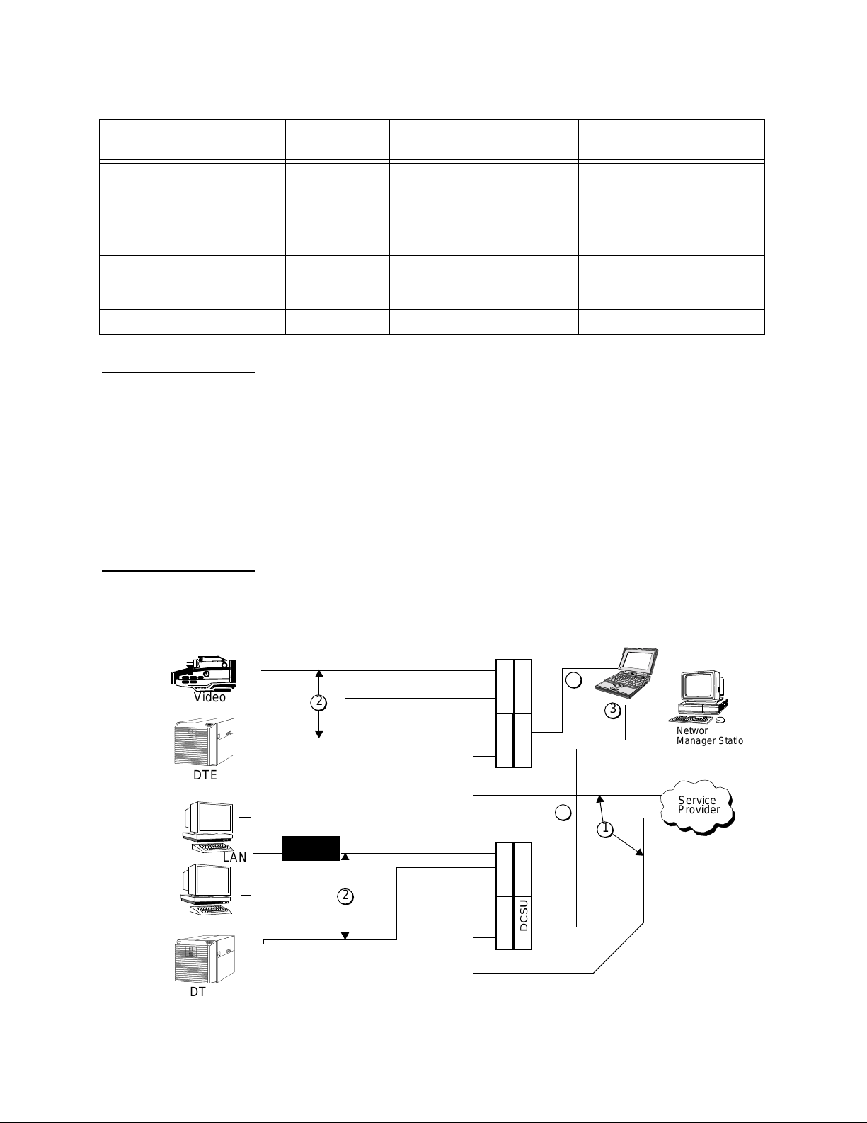
Figure 1-5 shows the type s of ca bl e co nn ecti ons f or a DI DCSU 2 912
system.
Figure 1-5 DIDCSU Cable Connection Diagram
Video
DTE
LAN
DT
2
Router
2
CIMCIMCIMCIM
DIDCSUDIDCSUDIDCSUDIDCSU
Shelf 1
Shelf 2
5
3
Networ
Manager Station
Service
4
1
Provider
1-8
Verilink DIDCSU 2912 User Manual
Page 15

DIDCSU 2912 Overview
1. Network interface cabl es
2. High-speed data application cables
3. Primary manageme nt cable to enable Node Manager
communication
4. Management extension cable for connecting DIDCSU modules
in multiple-shelf configurations (if the NCM module is
installed)
5. Craft cable to AS CII terminal (P/N 458-102119-008)
Verilink DIDCSU 2912 User Manual
1-9
Page 16

DIDCSU 2912 Overview
Specifications
Table 1-3 DIDCSU Specifications
Item Specification
Number of ports
Transmission (Line) rate
4 per module (2 network and 2 data)
T1—1.544 Mbit/s, RX: ± 200 ppm; TX: ± 32 ppm
E1—2.04 Mbit/s, RX: ± 200 ppm; TX: ± 32ppm
Line code
T1—B8ZS, AMI
E1—HDB3
Framing format
T1—ESF, SF
E1—CRC-4
CPE impedance
T1—100 Ω ± 5% at 772 KHz test
E1—120 Ω
Input level CIMs:
Output level
Output LBO (selectable)
Loopbacks
Timing
3.0 V ± 0.3 V base-to-peak, or DS1 into 100 Ω at 0 dB LBO, DSX-1
0, 7.5, 15, or 22.5 dB (0 to 3000 feet)
Line, Data port, Repeater, Payload
Modes: Network, External, and Internal
External System Port T1—8-pin DIN
External System Port E1—BNC, 8-pin DIN
Operating temperature
Storage temperature
Humidity
o
C to +50o C
0
-20o C to +80o C
5% to 95%, relative, non-condensing
± 5%
or 75 Ω
@ 1024 KHz
± 5%
3.0 V ± 0.3 V base-to-p e a k , att e n ua t ed by 0 t o 27. 5 d B
Input voltage range
Power consumption
Front module input voltage
requirement
Front module current requirement
CIM input voltage requirement
CIM current requirement
+ 5.5 V
DC
@ 4 A
10 watts per card, maximum
+ 5.5 V
DC
1.1 A
+ 5.0 V
700 mA
DC
DC
1-10
Verilink DIDCSU 2912 User Manual
Page 17

DIDCSU 2912 Overview
Table 1-4 CIM Configurations
CIM Line Type External Timing Net Port Type Data Port Type
29010 T1 8-pin DIN du al RJ-48C dual V.35
29011 T1 8-pin DIN du al RJ-48C dual EIA 530/RS-449
29004 E1 50Ω BNC dual 75Ω BNC dual X.21
29005 E1 50Ω BNC dual 75Ω BNC dual V.35
29006 E1 50Ω BNC dual 120Ω DE-9 dual X.21
29007 E1 50Ω BNC dual 120Ω DE-9 dual V.35
29008, 29008LP
29009,29009LP
*
*
E1 8-pin DIN dual 75Ω BNC dual EIA 530/RS-449
E1 8-pin DIN dual 120Ω RJ-45 dual EIA 530/RS-449
* LP = Lightning Protection (if an E1 CIM does not have an “LP” label
on it, it has no lightning protection.)
NOTE:
E1 CIMs 29008 and 29009 and T1 CIM 290011 combine RS449 and EIA 530 in the same module. However, the
equipment adapter cables for RS-449 and EIA 530 are
different.
Verilink DIDCSU 2912 User Manual
1-11
Page 18

DIDCSU 2912 Overview
1-12
Verilink DIDCSU 2912 User Manual
Page 19

Chapter
2
T1 Quick Set-Up
DIDCSU 2912 Quick Set-Up
This chapter is divided into two main sections. The first section
provides step-by-step procedures for installing your DIDCSU 2912
module on a T1 circuit. The second portion of this chapter provides
step-by-step procedures for an E1 installation.
This quick configuration guide makes the following assumptions:
•
You are installing the DIDCSU 2912 in a dual-line shelf with an
NCM 2000 module.
•
You are connecting two T1 facilities—one an FT1 using 12
DS0s, the other a full T1 with 24 DS0s—to the two network
ports of the DIDCSU 2912.
•
The full T1 connects to Net Port 1 and all of the timeslots are
mapped to Data Port 1, the fractional T1 is connected to Net
Port 2 and the first 12 DS0s are mapped to Data Port 2.
Connect to Craft Port
•
The NCM 2000 controller module is in slot 1 and the DIDCSU is
in slot 2.
Figure 2-1 E xample Configuration
Management
Terminal
NOTE:
Connect the modular (RJ-11) end of the Craft cable (P/N 458102119-008) to the port labeled
controller module. Connect the other end of the Craft cable to your
PC or terminal.
These procedures may not match your configuration. Use this
chapter as a guide for equ ipment installation. DIDCSU T1
Version has complete details on configuration of the T1
mode.
Fractional
T1
12 DS0s
LOCAL
Full T1
24 DS0s
on the front panel of the NCM
Verilink DIDCSU 2912 User Manual
2-1
Page 20

DIDCSU 2912 Quick Set-Up
Terminal Parameters
Logging On
Set your terminal, or terminal program, to
•
19.2 kbit/s
•
8 data bits
•
no parity
•
one stop bit
•
no flow control
NTER
E
.
1. Press
press
NTER
E
The
.
pSH+>
prompt is displayed. Type “craft” and
2. A password prompt appears. Initially there is no password,
press
If the NCM
NTER
E
to display the NCM
Main Menu
display (Figure 2-2) shows the DIDCSU in the
Main Menu
proper shelf/slot position (letter A in slot 2), go to Step 10.
Figure 2-2 NCM Main Menu
-- VERILINK NCM CONTROLLER : FW Rev 4.33, May 18 1999 11:10:17 --
-- VERILINK NCM CONTROLLER : FW Rev 4.33, May 18 1999 11:10:17 --
-- VERILINK NCM CONTROLLER : FW Rev 4.33, May 18 1999 11:10:17 ---- VERILINK NCM CONTROLLER : FW Rev 4.33, May 18 1999 11:10:17 --
Site Name: Tech Pubs & Trainin Access Level: 2
Site Name: Tech Pubs & Trainin Access Level: 2
Site Name: Tech Pubs & Trainin Access Level: 2 Site Name: Tech Pubs & Trainin Access Level: 2
Managing at NEAR end node [0.0.0.204] Node ID: 204
Managing at NEAR end node [0.0.0.204] Node ID: 204
Managing at NEAR end node [0.0.0.204] Node ID: 204 Managing at NEAR end node [0.0.0.204] Node ID: 204
.
<- SLOT ->
<- SLOT ->
<- SLOT -> <- SLOT ->
SHELF 1 2 3 4 5 6 7 8 9 10 11 12 13
SHELF 1 2 3 4 5 6 7 8 9 10 11 12 13
SHELF 1 2 3 4 5 6 7 8 9 10 11 12 13 SHELF 1 2 3 4 5 6 7 8 9 10 11 12 13
0 - - - - - - - - - - - - -
0 - - - - - - - - - - - - -
0 - - - - - - - - - - - - - 0 - - - - - - - - - - - - 1 D [*N] A
1 D [*N] A
1 D [*N] A 1 D [*N] A
2 - - - - - - - - - - - - -
2 - - - - - - - - - - - - -
2 - - - - - - - - - - - - - 2 - - - - - - - - - - - - 3 - - - - - - - - - - - - -
3 - - - - - - - - - - - - -
3 - - - - - - - - - - - - - 3 - - - - - - - - - - - - 4 - - - - - - - - - - - - -
4 - - - - - - - - - - - - -
4 - - - - - - - - - - - - - 4 - - - - - - - - - - - - KEY: A=didcsu B=diu/dbu C=csu D=diu E=sdiu F=diu/dds G=dhdm
KEY: A=didcsu B=diu/dbu C=csu D=diu E=sdiu F=diu/dds G=dhdm
KEY: A=didcsu B=diu/dbu C=csu D=diu E=sdiu F=diu/dds G=dhdmKEY: A=didcsu B=diu/dbu C=csu D=diu E=sdiu F=diu/dds G=dhdm
H=atm/imux I=idcsu J=pep K=dac L=hlm M=imux N=ncm
H=atm/imux I=idcsu J=pep K=dac L=hlm M=imux N=ncm
H=atm/imux I=idcsu J=pep K=dac L=hlm M=imux N=ncm H=atm/imux I=idcsu J=pep K=dac L=hlm M=imux N=ncm
P=dpri Q=quad R=subrate S=hsm T=hdm U=dcsu
P=dpri Q=quad R=subrate S=hsm T=hdm U=dcsu
P=dpri Q=quad R=subrate S=hsm T=hdm U=dcsu P=dpri Q=quad R=subrate S=hsm T=hdm U=dcsu
V=vcu W= dhdm_poet X=qpri ?=unknown
V=vcu W= dhdm_poet X=qpri ?=unknown
V=vcu W= dhdm_poet X=qpri ?=unknown V=vcu W= dhdm_poet X=qpri ?=unknown
S) shelf/slot O) administration
S) shelf/slot O) administration
S) shelf/slot O) administrationS) shelf/slot O) administration
C) configuration D) diagnostics
C) configuration D) diagnostics
C) configuration D) diagnosticsC) configuration D) diagnostics
P) performance/status A) alarm
P) performance/status A) alarm
P) performance/status A) alarmP) performance/status A) alarm
B) circuit manager I) manufacturing info
B) circuit manager I) manufacturing info
B) circuit manager I) manufacturing infoB) circuit manager I) manufacturing info
X) exit this screen
X) exit this screen
X) exit this screenX) exit this screen
A [0.0.0.204] [1,1] NCM 2000 >
A [0.0.0.204] [1,1] NCM 2000 >
A [0.0.0.204] [1,1] NCM 2000 >A [0.0.0.204] [1,1] NCM 2000 >
2-2
Verilink DIDCSU 2912 User Manual
Page 21

DIDCSU 2912 Quick Set-Up
Bus Compatibility
3. If there is no indication of the DIDCSU in the shelf/slot map on
the NCM
Main Menu
, examine the
SYS
LED on the DIDCSU. If it
is blinking green-to-off, the DIDCSU is using a different shelf
midplane bus th a n th e NC M.
NCMs are shipped with the C bus as the default bus. Other
modules are shipped with the A bus as a default.
To assign the DIDCSU to the same bus as the NCM proceed to
Step 4.
4. Temporarily connect the Craft cable to th e
DIDCSU module. Press
pSH+>
pSH+>
prompt is displayed, go to Step 6. If the prompt
is displayed , type “cr aft” and pr ess
5. If no
ENTER
.
lowercase characters.
6. At the
Main Menu
Figure 2-3 DIDCSU Main Menu
-- VERILINK ACE CONTROLLER at [1,2]: FW Rev 3.02, Apr 20 1999 --
-- VERILINK ACE CONTROLLER at [1,2]: FW Rev 3.02, Apr 20 1999 --
-- VERILINK ACE CONTROLLER at [1,2]: FW Rev 3.02, Apr 20 1999 ---- VERILINK ACE CONTROLLER at [1,2]: FW Rev 3.02, Apr 20 1999 --
Site Name:
Site Name:
Site Name:Site Name:
Access level: 4
Access level: 4
Access level: 4Access level: 4
<- SLOT ->
<- SLOT ->
<- SLOT -> <- SLOT ->
SHELF 1 2 3 4 5 6 7 8 9 10 11 12 13
SHELF 1 2 3 4 5 6 7 8 9 10 11 12 13
SHELF 1 2 3 4 5 6 7 8 9 10 11 12 13 SHELF 1 2 3 4 5 6 7 8 9 10 11 12 13
0 - - - - - - - - - - - - -
0 - - - - - - - - - - - - -
0 - - - - - - - - - - - - - 0 - - - - - - - - - - - - 1 M *N [A] - - - - - - - - - - -
1 M *N [A] - - - - - - - - - - -
1 M *N [A] - - - - - - - - - - - 1 M *N [A] - - - - - - - - - - 2 - - - - - - - - - - - - -
2 - - - - - - - - - - - - -
2 - - - - - - - - - - - - - 2 - - - - - - - - - - - - 3 - - - - - - - - - - - - -
3 - - - - - - - - - - - - -
3 - - - - - - - - - - - - - 3 - - - - - - - - - - - - 4 - - - - - - - - - - - - -
4 - - - - - - - - - - - - -
4 - - - - - - - - - - - - - 4 - - - - - - - - - - - - 5 - - - - - - - - - - - - -
5 - - - - - - - - - - - - -
5 - - - - - - - - - - - - - 5 - - - - - - - - - - - - 6 - - - - - - - - - - - - -
6 - - - - - - - - - - - - -
6 - - - - - - - - - - - - - 6 - - - - - - - - - - - - 7 - - - - - - - - - - - - -
7 - - - - - - - - - - - - -
7 - - - - - - - - - - - - - 7 - - - - - - - - - - - - KEY: *=CONTROLLER N=NCM Q=QUAD M=IMUX A=DIDCSU P=DPRI X=QPRI U=DCSU
KEY: *=CONTROLLER N=NCM Q=QUAD M=IMUX A=DIDCSU P=DPRI X=QPRI U=DCSU
KEY: *=CONTROLLER N=NCM Q=QUAD M=IMUX A=DIDCSU P=DPRI X=QPRI U=DCSUKEY: *=CONTROLLER N=NCM Q=QUAD M=IMUX A=DIDCSU P=DPRI X=QPRI U=DCSU
YOUR PASSWORD?
is displayed.
prompt, press
LOCAL
ENTER
NTER
E
. The DIDCSU
port on the
. Be sure t o use
S) shelf/slot O) node administration
S) shelf/slot O) node administration
S) shelf/slot O) node administrationS) shelf/slot O) node administration
C) configuration D) diagnostics
C) configuration D) diagnostics
C) configuration D) diagnosticsC) configuration D) diagnostics
P) performance/status A) alarm
P) performance/status A) alarm
P) performance/status A) alarmP) performance/status A) alarm
B) circuit I) manufacturing info
B) circuit I) manufacturing info
B) circuit I) manufacturing infoB) circuit I) manufacturing info
X) system log off
X) system log off
X) system log offX) system log off
[1,2] DIDCSU 2912 >
[1,2] DIDCSU 2912 >
[1,2] DIDCSU 2912 >[1,2] DIDCSU 2912 >
7. From the DIDCSU
Administration
Main Menu
,
then “B” to
Observe that the current ACP bus selection is indicated.
Change the ACP bus selection to the other value (A or C).
Verilink DIDCSU 2912 User Manual
, select the letter “O” for
Change ACP Bus
.
Node
2-3
Page 22

DIDCSU 2912 Quick Set-Up
8. Once the bus assignment has been made, reboot the DIDCSU
by reseating the front module in its slot.
OCAL
L
9. Reconnect the Craft ca ble to th e NCM
port. When the
DIDCSU 2912 has completed the reset a process of negotiation
for shelf master will occur. Duri ng this ti me the
DIDCSU will be amber. Once the
SYS
LED becomes steady
SYS
LED on the
green, the NCM has control of the DIDCSU—proceed to step 10.
Configure Network Port
10. From the NCM Craft inter f a c e
the DIDCSU application module using option “S”, Shelf/Slot.
Note that now the
letter A, indicating the DIDCSU is the currently selected
module.
11. From the
Main Menu
configuration task.
Figure 2-4 Configuration Menu
-- DIDCSU 2912 CONFIGURATION MENU --
-- DIDCSU 2912 CONFIGURATION MENU --
-- DIDCSU 2912 CONFIGURATION MENU -- -- DIDCSU 2912 CONFIGURATION MENU --
P) T1 port D) data port
P) T1 port D) data port
P) T1 port D) data portP) T1 port D) data port
X) exit this screen
X) exit this screen
X) exit this screenX) exit this screen
A [0.0.0.204] [1,2] DIDCSU 2912 >
A [0.0.0.204] [1,2] DIDCSU 2912 >
A [0.0.0.204] [1,2] DIDCSU 2912 >A [0.0.0.204] [1,2] DIDCSU 2912 >
12. From the
access the
Configuration Menu
T1 Port Configuration Menu
Main Menu
Main Menu
shows brackets around the
(Figure 2-2), select
, select option “C” to start the
(Figure 2-4), select option “P” to
(Figure 2-5).
2-4
Verilink DIDCSU 2912 User Manual
Page 23

Figure 2-5 T1 Port Configuration Menu
-- DIDCSU 2912 T1 PORT CONFIGURATION MENU --
-- DIDCSU 2912 T1 PORT CONFIGURATION MENU --
-- DIDCSU 2912 T1 PORT CONFIGURATION MENU ---- DIDCSU 2912 T1 PORT CONFIGURATION MENU --
PORT 1 PORT 2
PORT 1 PORT 2
PORT 1 PORT 2 PORT 1 PORT 2
In) In Service YES YES
In) In Service YES YES
In) In Service YES YESIn) In Service YES YES
Fn) Frame Format SF ESF
Fn) Frame Format SF ESF
Fn) Frame Format SF ESFFn) Frame Format SF ESF
Ln) Line Coding AMI AMI
Ln) Line Coding AMI AMI
Ln) Line Coding AMI AMILn) Line Coding AMI AMI
Bn) Line Build Out 0db 0db
Bn) Line Build Out 0db 0db
Bn) Line Build Out 0db 0dbBn) Line Build Out 0db 0db
NDn) Network Density NONE NONE
NDn) Network Density NONE NONE
NDn) Network Density NONE NONENDn) Network Density NONE NONE
NLn) Network Initiated Loop NO NO
NLn) Network Initiated Loop NO NO
NLn) Network Initiated Loop NO NONLn) Network Initiated Loop NO NO
An) Alarm Declare Time(sec) 0 0
An) Alarm Declare Time(sec) 0 0
An) Alarm Declare Time(sec) 0 0An) Alarm Declare Time(sec) 0 0
DLn) FDL Enable NO NO
DLn) FDL Enable NO NO
DLn) FDL Enable NO NODLn) FDL Enable NO NO
PRM Enable NO NO
PRM Enable NO NO
PRM Enable NO NO PRM Enable NO NO
En) Enable Inband/ISDN both dis both dis
En) Enable Inband/ISDN both dis both dis
En) Enable Inband/ISDN both dis both disEn) Enable Inband/ISDN both dis both dis
Sn) Inband Timeslot 1 1
Sn) Inband Timeslot 1 1
Sn) Inband Timeslot 1 1Sn) Inband Timeslot 1 1
F) FDL configuration
F) FDL configuration
F) FDL configurationF) FDL configuration
T) Timing
T) Timing
T) TimingT) Timing
X) Exit this screen
X) Exit this screen
X) Exit this screenX) Exit this screen
DIDCSU 2912 Quick Set-Up
A [0.0.0.204] [1,2] DIDCSU 2912 >
A [0.0.0.204] [1,2] DIDCSU 2912 >
A [0.0.0.204] [1,2] DIDCSU 2912 >A [0.0.0.204] [1,2] DIDCSU 2912 >
Place Ports In
Service
13. In the
number “1”, press
place Net Port 1 In Service. Type “I2”, press
respond by pressing “Y”,
NOTE:
For the remainder of this section you will not be instructed
each time you should press the
used after each command or text entry.
Select ESF Framing
14. Type “F1”, and “2” for ESF framing for Net Port 1. Type “F2”
and “2” for ESF framing for Net Port 2.
Select B8ZS Line
Coding
15. Type “L1”, then “2” to select B8ZS as the line coding for Net
Port 1. Type “L2”, then “2” to select B8ZS as the line coding for
Net Port 2.
Set Line Build Out
to 0db
16. Type “B1”, then “1” to sel e ct 0db as the line build out for Net
Port 1. Type “B2”, th en “1” to select 0db as the lin e build out
for Net Port 2.
T1 Port Configuration Menu
NTER
E
, then type “Y”,and press
NTER
E
, to place Net Port 2 In Service.
E
, type the letter “I” and the
NTER
E
, to
NTER
E
, then
NTER
key. In general,
NTER
E
is
Set Density
Enforcement to
None
17. Type “ND1”, then “1” to select NONE as the network density
for Net Port 1. Type “ND2”, then “1” to select NONE as the
network density for Net Port 2.
Verilink DIDCSU 2912 User Manual
2-5
Page 24

DIDCSU 2912 Quick Set-Up
Allow Network
Originated Loops
Set Alarm Declare
Time to 2 Seconds
Disable Facilities
Data Link
Select no DS0 for
Inband
Management
Disable Inband
Management
18. Type “NL1”, then “Y” to allow network initiated loops on Net
Port 1. Type “NL2”, then “Y” to allow network initiated loops
on Net Port 2.
19. Type “A1”, then “2” to set the number of elapsed seconds
before declaring an alarm co ndition for Net Port 1. Type “A2”,
then “2” to set the number of elapsed seconds before
declaring an alarm co ndition for Net Port 2.
20. We do not need FDL connectivity to the far-end. Type “DL1”,
then “N” to disable FDL for Net Por t 1. Typ e “DL2”, then “N” to
disable FDL for Net Port 2.
21. “S1” and “S2” are not used because no inband timeslot (DS0) is
reserved for management in this exa mpl e.
22. Type “E1”, then “2” to disable inband for bo th ports.
Timing Options
23. From the
Options
Figure 2-6 Timing Options
-- DIDCSU 2912 CONFIGURATION MENU (TIMING OPTIONS)--
-- DIDCSU 2912 CONFIGURATION MENU (TIMING OPTIONS)--
-- DIDCSU 2912 CONFIGURATION MENU (TIMING OPTIONS)---- DIDCSU 2912 CONFIGURATION MENU (TIMING OPTIONS)--
Current shelf timing source: Card 2, NET 1 (PRIMARY)
Current shelf timing source: Card 2, NET 1 (PRIMARY)
Current shelf timing source: Card 2, NET 1 (PRIMARY)Current shelf timing source: Card 2, NET 1 (PRIMARY)
Source Slot Number Synchronization Auto Restore
Source Slot Number Synchronization Auto Restore
Source Slot Number Synchronization Auto RestoreSource Slot Number Synchronization Auto Restore
PRIMARY PC) 2 PS) NET 1 PA) YES
PRIMARY PC) 2 PS) NET 1 PA) YES
PRIMARY PC) 2 PS) NET 1 PA) YESPRIMARY PC) 2 PS) NET 1 PA) YES
SECONDARY SC) 2 SS) NET 2 SA) YES
SECONDARY SC) 2 SS) NET 2 SA) YES
SECONDARY SC) 2 SS) NET 2 SA) YESSECONDARY SC) 2 SS) NET 2 SA) YES
TERTIARY TC) 2 TS) INTERNAL TA) YES
TERTIARY TC) 2 TS) INTERNAL TA) YES
TERTIARY TC) 2 TS) INTERNAL TA) YESTERTIARY TC) 2 TS) INTERNAL TA) YES
R) Receive clock from shelf: YES
R) Receive clock from shelf: YES
R) Receive clock from shelf: YESR) Receive clock from shelf: YES
X) exit this screen
X) exit this screen
X) exit this screenX) exit this screen
Configuration Menu
submenu.
24. Type “R”, then “Y”, and press
Observe that some of the menu items change depe ndi ng on
Receive clock from shelf
whether the
Use the PC, PS, PA, SC, SS, SA, TC, TS and TA commands to
configure the DIDCSU as shown in Figure 2-6.
, select “T” for the
NTER
E
to refresh the screen.
option is YES, or NO.
Timing
2-6
25. Use “X” to ex it to th e T1
”
”
“X
again to exit to the
” ”
Verilink DIDCSU 2912 User Manual
Configuration Menu
Port Configuration Menu
.
. Then use
Page 25

DIDCSU 2912 Quick Set-Up
Data Port Configuration
Figure 2-7 Configuration Menu
A [0.0.0.204] [1,2] DIDCSU 2912 > c
A [0.0.0.204] [1,2] DIDCSU 2912 > c
A [0.0.0.204] [1,2] DIDCSU 2912 > c A [0.0.0.204] [1,2] DIDCSU 2912 > c
-- DIDCSU 2912 CONFIGURATION MENU --
-- DIDCSU 2912 CONFIGURATION MENU --
-- DIDCSU 2912 CONFIGURATION MENU ---- DIDCSU 2912 CONFIGURATION MENU -P) T1 port D) data port
P) T1 port D) data port
P) T1 port D) data portP) T1 port D) data port
X) exit this screen
X) exit this screen
X) exit this screenX) exit this screen
A [0.0.0.204] [1,2] DIDCSU 2912 >
A [0.0.0.204] [1,2] DIDCSU 2912 >
A [0.0.0.204] [1,2] DIDCSU 2912 >A [0.0.0.204] [1,2] DIDCSU 2912 >
Figure 2-8 Data Port Configuration Menu
-- DIDCSU 2912 DATA PORT CONFIGURATION MENU --
-- DIDCSU 2912 DATA PORT CONFIGURATION MENU --
-- DIDCSU 2912 DATA PORT CONFIGURATION MENU ---- DIDCSU 2912 DATA PORT CONFIGURATION MENU --
PORT 1 PORT 2
PORT 1 PORT 2
PORT 1 PORT 2 PORT 1 PORT 2
In) In Service YES YES
In) In Service YES YES
In) In Service YES YESIn) In Service YES YES
Mn) Data Port Mode DCE DCE
Mn) Data Port Mode DCE DCE
Mn) Data Port Mode DCE DCEMn) Data Port Mode DCE DCE
Cn) Clock Option ST ST
Cn) Clock Option ST ST
Cn) Clock Option ST STCn) Clock Option ST ST
On) Enable LOS detection NO NO
On) Enable LOS detection NO NO
On) Enable LOS detection NO NOOn) Enable LOS detection NO NO
Ln) Control Lead Mode AUTO AUTO
Ln) Control Lead Mode AUTO AUTO
Ln) Control Lead Mode AUTO AUTOLn) Control Lead Mode AUTO AUTO
SRn) Forced DTR/DSR DSR/LOW DSR/LOW
SRn) Forced DTR/DSR DSR/LOW DSR/LOW
SRn) Forced DTR/DSR DSR/LOW DSR/LOWSRn) Forced DTR/DSR DSR/LOW DSR/LOW
SSn) Forced RTS/CTS CTS/LOW CTS/LOW
SSn) Forced RTS/CTS CTS/LOW CTS/LOW
SSn) Forced RTS/CTS CTS/LOW CTS/LOWSSn) Forced RTS/CTS CTS/LOW CTS/LOW
SDn) Forced LLB/DCD DCD/LOW DCD/LOW
SDn) Forced LLB/DCD DCD/LOW DCD/LOW
SDn) Forced LLB/DCD DCD/LOW DCD/LOWSDn) Forced LLB/DCD DCD/LOW DCD/LOW
SMn) Forced RLB/TM TM /LOW TM /LOW
SMn) Forced RLB/TM TM /LOW TM /LOW
SMn) Forced RLB/TM TM /LOW TM /LOWSMn) Forced RLB/TM TM /LOW TM /LOW
DTR/LOW DTR/LOW
DTR/LOW DTR/LOW
DTR/LOW DTR/LOW DTR/LOW DTR/LOW
RTS/LOW RTS/LOW
RTS/LOW RTS/LOW
RTS/LOW RTS/LOW RTS/LOW RTS/LOW
LLB/LOW LLB/LOW
LLB/LOW LLB/LOW
LLB/LOW LLB/LOW LLB/LOW LLB/LOW
RLB/LOW RLB/LOW
RLB/LOW RLB/LOW
RLB/LOW RLB/LOW RLB/LOW RLB/LOW
Cable PRESENT PRESENT
Cable PRESENT PRESENT
Cable PRESENT PRESENTCable PRESENT PRESENT
DPL Loopback DISABLE DISABLE
DPL Loopback DISABLE DISABLE
DPL Loopback DISABLE DISABLEDPL Loopback DISABLE DISABLE
Test Pattern NONE NONE
Test Pattern NONE NONE
Test Pattern NONE NONETest Pattern NONE NONE
Test Error Counter 0 0
Test Error Counter 0 0
Test Error Counter 0 0Test Error Counter 0 0
X) exit this screen
X) exit this screen
X) exit this screenX) exit this screen
26. From the
Data Port Configuration Menu
Configuration Menu
, select option “D” to access the
.
A [0.0.0.204] [1,2] DIDCSU 2912 >
A [0.0.0.204] [1,2] DIDCSU 2912 >
A [0.0.0.204] [1,2] DIDCSU 2912 >A [0.0.0.204] [1,2] DIDCSU 2912 >
27. In the
typing “Y”, to place Data Port 1 in service. Type “I2”, then “Y”,
to place Data Port 2 in Service.
28. Use “C1” and “C2” to set both data ports to ST clocking.
29. Type the letter “O” and “1”, then “1”to disable LOS Detection
for Data Port 1. Type the letter “O” and “2”, then “1” to disable
LOS Detection for Dat a Port 2.
Setting Alarm Parameters
When normal T1 service is interrupted, errored, or lost, an alarm is
triggered. Enable alarm reporting for the T1 and data ports you
want to monitor.
Verilink DIDCSU 2912 User Manual
Data Port Configuration Menu
, type “I1”, respond by
2-7
Page 26

DIDCSU 2912 Quick Set-Up
1. Select “A” from the
Port Alarm Menu
2. Set the
Figure 2-9 Net Port Alarm Menu
A [0.0.0.204] [1,2] DIDCSU 2912 > a
A [0.0.0.204] [1,2] DIDCSU 2912 > a
A [0.0.0.204] [1,2] DIDCSU 2912 > aA [0.0.0.204] [1,2] DIDCSU 2912 > a
-- DIDCSU 2912 NET PORT ALARM MENU --
-- DIDCSU 2912 NET PORT ALARM MENU --
-- DIDCSU 2912 NET PORT ALARM MENU ---- DIDCSU 2912 NET PORT ALARM MENU -N) NMS Address 128.0.0.0
N) NMS Address 128.0.0.0
N) NMS Address 128.0.0.0N) NMS Address 128.0.0.0
A) Card Alarm Reporting YES
A) Card Alarm Reporting YES
A) Card Alarm Reporting YESA) Card Alarm Reporting YES
C) Configure Thresholds S) Alarm status
C) Configure Thresholds S) Alarm status
C) Configure Thresholds S) Alarm statusC) Configure Thresholds S) Alarm status
O) Display Alarm Buffer Tn) Set Default Thresholds
O) Display Alarm Buffer Tn) Set Default Thresholds
O) Display Alarm Buffer Tn) Set Default ThresholdsO) Display Alarm Buffer Tn) Set Default Thresholds
X) exit this screen
X) exit this screen
X) exit this screenX) exit this screen
A [0.0.0.204] [1,2] DIDCSU 2912 >
A [0.0.0.204] [1,2] DIDCSU 2912 >
A [0.0.0.204] [1,2] DIDCSU 2912 >A [0.0.0.204] [1,2] DIDCSU 2912 >
Card Alarm Reporting
Main Menu
.
, Figure 2-1, to access the
option to YES.
3. Select “C” to configure thresholds.
Figure 2-10 Net Port Alarm Threshold Configuration Menu
-- DIDCSU 2912 NET PORT ALARM THRESHOLD CONFIGURATION MENU --
-- DIDCSU 2912 NET PORT ALARM THRESHOLD CONFIGURATION MENU --
-- DIDCSU 2912 NET PORT ALARM THRESHOLD CONFIGURATION MENU ---- DIDCSU 2912 NET PORT ALARM THRESHOLD CONFIGURATION MENU - PORT 1 PORT 2
PORT 1 PORT 2
PORT 1 PORT 2 PORT 1 PORT 2
Pn) Alarm Reporting(NET) YES YES
Pn) Alarm Reporting(NET) YES YES
Pn) Alarm Reporting(NET) YES YESPn) Alarm Reporting(NET) YES YES
Dn) Alarm Reporting(DATA) YES YES
Dn) Alarm Reporting(DATA) YES YES
Dn) Alarm Reporting(DATA) YES YESDn) Alarm Reporting(DATA) YES YES
Fn) LOF threshold 3 3
Fn) LOF threshold 3 3
Fn) LOF threshold 3 3Fn) LOF threshold 3 3
LOF interval 3 3
LOF interval 3 3
LOF interval 3 3 LOF interval 3 3
Ln) LOS threshold 3 3
Ln) LOS threshold 3 3
Ln) LOS threshold 3 3Ln) LOS threshold 3 3
LOS interval 3 3
LOS interval 3 3
LOS interval 3 3 LOS interval 3 3
Rn) RAI threshold 1 1
Rn) RAI threshold 1 1
Rn) RAI threshold 1 1Rn) RAI threshold 1 1
RAI interval 1 1
RAI interval 1 1
RAI interval 1 1 RAI interval 1 1
An) AIS threshold 1 1
An) AIS threshold 1 1
An) AIS threshold 1 1An) AIS threshold 1 1
AIS interval 1 1
AIS interval 1 1
AIS interval 1 1 AIS interval 1 1
Bn) BPV threshold 1 1
Bn) BPV threshold 1 1
Bn) BPV threshold 1 1Bn) BPV threshold 1 1
BPV interval 1 1
BPV interval 1 1
BPV interval 1 1 BPV interval 1 1
En) ES 15min threshold 900 900
En) ES 15min threshold 900 900
En) ES 15min threshold 900 900En) ES 15min threshold 900 900
ES 24hr threshold 86400 86400
ES 24hr threshold 86400 86400
ES 24hr threshold 86400 86400 ES 24hr threshold 86400 86400
Sn) SES 15min threshold 900 900
Sn) SES 15min threshold 900 900
Sn) SES 15min threshold 900 900Sn) SES 15min threshold 900 900
SES 24hr threshold 86400 86400
SES 24hr threshold 86400 86400
SES 24hr threshold 86400 86400 SES 24hr threshold 86400 86400
In) BER threshold DISABLE DISABLE
In) BER threshold DISABLE DISABLE
In) BER threshold DISABLE DISABLEIn) BER threshold DISABLE DISABLE
Tn) Set Default Threshold X) exit this screen
Tn) Set Default Threshold X) exit this screen
Tn) Set Default Threshold X) exit this screenTn) Set Default Threshold X) exit this screen
A [0.0.0.204] [1,2] DIDCSU 2912 >
A [0.0.0.204] [1,2] DIDCSU 2912 >
A [0.0.0.204] [1,2] DIDCSU 2912 >A [0.0.0.204] [1,2] DIDCSU 2912 >
Net
2-8
4. Enable Net Ports 1 and 2 A larm Reporting (N ET) by setting both
“P1”
and “P2” to YES.
5. Enable Data Ports 1 an d 2 Alarm Reporting (DATA) by setting
both “D1” and “D2” to YES.
6. Leave the remaining opti o ns at their default values.
Verilink DIDCSU 2912 User Manual
Page 27

DIDCSU 2912 Quick Set-Up
Building Circuits
Circuit building is a p rimar y f uncti on of th e N CM 2000 . For genera l
information on circuit building, refer to the
Manual
. This section provides “Quick Set-up” circuit building
information specifically for the DIDCSU 2912. For more details on
circuit building, refer to the section on circuit building in Chapter
DIDCSU T1 Version
3,
Build circuits using the
selecting “B” from the
Figure 2-11 Circuit Manager Menu
A [0.0.0.204] [1,2] DIDCSU 2912 > b
A [0.0.0.204] [1,2] DIDCSU 2912 > b
A [0.0.0.204] [1,2] DIDCSU 2912 > bA [0.0.0.204] [1,2] DIDCSU 2912 > b
Circuit Manager -- [1,1] NCM 2000 Firmware 4.18c --
Circuit Manager -- [1,1] NCM 2000 Firmware 4.18c --
Circuit Manager -- [1,1] NCM 2000 Firmware 4.18c --Circuit Manager -- [1,1] NCM 2000 Firmware 4.18c - >>>>>> NO CIRCUIT FOUND IN DATABASE <<<<<
>>>>>> NO CIRCUIT FOUND IN DATABASE <<<<<
>>>>>> NO CIRCUIT FOUND IN DATABASE <<<<< >>>>>> NO CIRCUIT FOUND IN DATABASE <<<<<
A) add circuit L) search circuit
A) add circuit L) search circuit
A) add circuit L) search circuit A) add circuit L) search circuit
D) delete circuit E) edit circuit
D) delete circuit E) edit circuit
D) delete circuit E) edit circuit D) delete circuit E) edit circuit
P) prev page I) activate circuit
P) prev page I) activate circuit
P) prev page I) activate circuit P) prev page I) activate circuit
N) next page R) deactivate circuit
N) next page R) deactivate circuit
N) next page R) deactivate circuit N) next page R) deactivate circuit
X) exit to craft main menu
X) exit to craft main menu
X) exit to craft main menu X) exit to craft main menu
A [0.0.0.204] [1,2] DIDCSU 2912 >
A [0.0.0.204] [1,2] DIDCSU 2912 >
A [0.0.0.204] [1,2] DIDCSU 2912 >A [0.0.0.204] [1,2] DIDCSU 2912 >
of this manual.
Circuit Manager Menu
Main Menu
When this menu is visited for the first time, and no circuits have
been built yet, the message
NO CIRCUIT FOUND IN DA TABASE
displayed. Type “A” to create a circuit through the
menu.
NCM 2000 User
, Figure 2-2.
, Figure 2-11 , by
is
Add Circuit
Figure 2-12 Add Circuit Menu
A [0.0.0.204] [1,2] DIDCSU 2912 > a
A [0.0.0.204] [1,2] DIDCSU 2912 > a
A [0.0.0.204] [1,2] DIDCSU 2912 > aA [0.0.0.204] [1,2] DIDCSU 2912 > a
Add Circuit -- [1,1] NCM 2000 Firmware 4.18c --
Add Circuit -- [1,1] NCM 2000 Firmware 4.18c --
Add Circuit -- [1,1] NCM 2000 Firmware 4.18c --Add Circuit -- [1,1] NCM 2000 Firmware 4.18c - N) Name: -- P) Priority: norm
N) Name: -- P) Priority: norm
N) Name: -- P) Priority: norm N) Name: -- P) Priority: norm
T) Type: -- M) Mode: --
T) Type: -- M) Mode: --
T) Type: -- M) Mode: -- T) Type: -- M) Mode: -SP) [-,-] undefined DP) [-,-] undefined
SP) [-,-] undefined DP) [-,-] undefined
SP) [-,-] undefined DP) [-,-] undefinedSP) [-,-] undefined DP) [-,-] undefined
SM) --src port chn-- DM) --dst port chn--
SM) --src port chn-- DM) --dst port chn--
SM) --src port chn-- DM) --dst port chn--SM) --src port chn-- DM) --dst port chn- (undefined port) (undefined port)
(undefined port) (undefined port)
(undefined port) (undefined port) (undefined port) (undefined port)
(undefined port) (undefined port)
(undefined port) (undefined port)
(undefined port) (undefined port) (undefined port) (undefined port)
(undefined port) (undefined port)
(undefined port) (undefined port)
(undefined port) (undefined port) (undefined port) (undefined port)
(undefined port) (undefined port)
(undefined port) (undefined port)
(undefined port) (undefined port) (undefined port) (undefined port)
U) Bus: -- ->-->>->> Circuit Inactive <<-<<--<-
U) Bus: -- ->-->>->> Circuit Inactive <<-<<--<-
U) Bus: -- ->-->>->> Circuit Inactive <<-<<--<- U) Bus: -- ->-->>->> Circuit Inactive <<-<<--< S) Setup X) Exit
S) Setup X) Exit
S) Setup X) Exit S) Setup X) Exit
A [0.0.0.204] [1,2] DIDCSU 2912 >
A [0.0.0.204] [1,2] DIDCSU 2912 >
A [0.0.0.204] [1,2] DIDCSU 2912 >A [0.0.0.204] [1,2] DIDCSU 2912 >
First Circuit
1. Type “N”, then at the prompt, type a n ame for the first circui t
(use “Circuit1”).
2. Type “P”, then select “2” for normal.
3. Type “T”, then at the prompt select “1” for permanent.
4. Type “M”, then at the prompt select “1” for 64K because the T1
facilities use B8ZS line coding.
Verilink DIDCSU 2912 User Manual
2-9
Page 28

DIDCSU 2912 Quick Set-Up
5. Type “SP”, then at the prompt use “1,2”, to specify the shelf
and slot address for the source port. When you’ve entered the
address, at the next prompt select “1” for Net Port 1.
6. Type “DP”, then at the prompt, specify the shelf and slot
address for the destination port. Use “1,2”. At t he next pr ompt
select “3” for Data Port 1.
7. Type “SM”, and r espond “N” if you are asked whether thi s is an
unframed T1 circuit. Type “1
----
24” to specify timeslots 1
through 24.
8. Type “DM”. Type “1
----
24” to specify timeslots 1 through 24.
9. Type “U” to assign the bus. No bus is required for this circuit,
so the menu returns with the bus field set to INT.
10. Type “S” to set up the circuit. Th e message
build
is displayed.
Figure 2-13 Circuit Manager Menu (With First Circuit Added)
Circuit Manager -- [1,1] NCM 2000 Firmware 4.33 --
Circuit Manager -- [1,1] NCM 2000 Firmware 4.33 --
Circuit Manager -- [1,1] NCM 2000 Firmware 4.33 --Circuit Manager -- [1,1] NCM 2000 Firmware 4.33 --
Page : 1
Page : 1
Page : 1 Page : 1
Total: 1 circuits
Total: 1 circuits
Total: 1 circuits Total: 1 circuits
Name Type Mode Prio Src Port Dest Port Bus Status
Name Type Mode Prio Src Port Dest Port Bus Status
Name Type Mode Prio Src Port Dest Port Bus Status Name Type Mode Prio Src Port Dest Port Bus Status
------------ ---- ---- ---- ---------------- ---------------- --- ------
------------ ---- ---- ---- ---------------- ---------------- --- ------
------------ ---- ---- ---- ---------------- ---------------- --- ------------------ ---- ---- ---- ---------------- ---------------- --- -----Circuit1 perm 64k norm [1, 2] DIDC net1 [1, 2] DIDC dat1 INT Active
Circuit1 perm 64k norm [1, 2] DIDC net1 [1, 2] DIDC dat1 INT Active
Circuit1 perm 64k norm [1, 2] DIDC net1 [1, 2] DIDC dat1 INT ActiveCircuit1 perm 64k norm [1, 2] DIDC net1 [1, 2] DIDC dat1 INT Active
A) add circuit L) search circuit
A) add circuit L) search circuit
A) add circuit L) search circuit A) add circuit L) search circuit
D) delete circuit E) edit circuit
D) delete circuit E) edit circuit
D) delete circuit E) edit circuit D) delete circuit E) edit circuit
P) prev page I) activate circuit
P) prev page I) activate circuit
P) prev page I) activate circuit P) prev page I) activate circuit
N) next page R) deactivate circuit
N) next page R) deactivate circuit
N) next page R) deactivate circuit N) next page R) deactivate circuit
Successful circuit
X) exit to craft main menu
X) exit to craft main menu
X) exit to craft main menu X) exit to craft main menu
A [0.0.0.204] [1,2] DIDCSU 2912 >
A [0.0.0.204] [1,2] DIDCSU 2912 >
A [0.0.0.204] [1,2] DIDCSU 2912 >A [0.0.0.204] [1,2] DIDCSU 2912 >
Second Circuit
11. Type “N”, then at the prompt, type “Circuit2
the next circuit (no more than 12 characters).
12. Type “P”, then type “2” for normal.
13. Type “T”, then at the prompt type “1” to select permanent.
14. Type “M”, then at the prompt type “1” for 64K.
15. Type “SP”, then at the prompt use “1,2” for the shelf/slot
address. At the next prom pt typ e “2 ” for Ne t Port 2.
2-10
Verilink DIDCSU 2912 User Manual
””””
as the name for
Page 29

DIDCSU 2912 Quick Set-Up
E1 Quick Set-Up
16. Type “DP”, then at the prompt use “1,2”
for the shelf/slot
address. At the next pr om pt typ e “4” fo r Da t a Port 2.
17. Type “SM”, and respo nd “N” if you are asked whet her this i s an
unframed T1 circuit. Type “1-12” to specify the timeslots.
18. Type “DM”, and respond “N” if you are asked whether this is
an unframed T1 circuit. Type “1-12” to specify the timeslots.
19. Type “U” to assign the bus. As with the first circuit, no bus i s
required because the source and destination ports are on the
same DIDCSU module. The menu retur ns with the bus set to
INT.
20. Type “S” to se t up the ci rcuit. A prompt is displ ayed ind icating
a successful circuit build.
21. Connect the two T1 circui ts. Observe that the front panel NET
LEDs turn green within 15 seconds.
22. Connect the Data Termi nal Equipment (DTE ).
This quick configuration guide makes the following assumptions:
•
You are installing the DIDCSU 2912 in a dual-line shelf with an
NCM 2000 module .
•
You are connecting two E1 facilities—one a fractional E1 using
15 DS0s, the other a full E1 with 30 DS0s—to the two network
ports of the DIDCSU 2912.
•
The full E1 connects to Net Port 1 and all of the timeslots are
mapped to Data Port 1, the fractional E1 is co nnected to Net
Port 2 and the first 15 DS0s are mapped to Data Port 2.
•
The NCM 2000 controller module is in slot 1 and the DIDCSU is
in slot 2.
Figure 2-14 Example Configuration
Management
Terminal
Fractional
E1
15 DS0s
Full E1
30 DS0s
Verilink DIDCSU 2912 User Manual
2-11
Page 30

DIDCSU 2912 Quick Set-Up
Connect to Craft Port
Terminal Parameters
NOTE:
Connect the modular (RJ-11) end of the Craft cable (P/N 458102119-008) to the port labeled
controller module. Connect the other end of the Craft cable to your
PC or terminal.
Set your terminal, or terminal program to:
These procedures may not match your configuration. Use this
chapter as a guide for equ ipment installation. Chapter 4,
“DIDCSU E1 Ver sion” has co mplete details on configuration of
the E1 mode.
LOCAL
on the front panel of the NCM
•
19.2 kbit/s
•
8 data bits
•
no parity
•
one stop bit
•
no flow control
Logging On
NTER
E
.
1. Press
2. A password prompt appears. Initially there is no password,
NTER
E
press
If the NCM
the proper shelf/slot position (letter A in slot 2), go to Step 10.
Main Menu
pSH+>
The
to display the NCM
prompt is displayed. Type “ craft”.
display (Figure 2-15) shows the DIDCSU in
Main Menu
.
2-12
Verilink DIDCSU 2912 User Manual
Page 31

DIDCSU 2912 Quick Set-Up
Figure 2-15 NCM Main Menu
-- VERILINK NCM CONTROLLER : FW Rev 4.33, May 18 1999 11:10:17 --
-- VERILINK NCM CONTROLLER : FW Rev 4.33, May 18 1999 11:10:17 --
-- VERILINK NCM CONTROLLER : FW Rev 4.33, May 18 1999 11:10:17 ---- VERILINK NCM CONTROLLER : FW Rev 4.33, May 18 1999 11:10:17 --
Site Name: Tech Pubs & Trainin Access Level: 2
Site Name: Tech Pubs & Trainin Access Level: 2
Site Name: Tech Pubs & Trainin Access Level: 2 Site Name: Tech Pubs & Trainin Access Level: 2
Managing at NEAR end node [0.0.0.204] Node ID: 204
Managing at NEAR end node [0.0.0.204] Node ID: 204
Managing at NEAR end node [0.0.0.204] Node ID: 204 Managing at NEAR end node [0.0.0.204] Node ID: 204
<- SLOT ->
<- SLOT ->
<- SLOT -> <- SLOT ->
SHELF 1 2 3 4 5 6 7 8 9 10 11 12 13
SHELF 1 2 3 4 5 6 7 8 9 10 11 12 13
SHELF 1 2 3 4 5 6 7 8 9 10 11 12 13 SHELF 1 2 3 4 5 6 7 8 9 10 11 12 13
0 - - - - - - - - - - - - -
0 - - - - - - - - - - - - -
0 - - - - - - - - - - - - - 0 - - - - - - - - - - - - 1 D [*N] A
1 D [*N] A
1 D [*N] A 1 D [*N] A
2 - - - - - - - - - - - - -
2 - - - - - - - - - - - - -
2 - - - - - - - - - - - - - 2 - - - - - - - - - - - - 3 - - - - - - - - - - - - -
3 - - - - - - - - - - - - -
3 - - - - - - - - - - - - - 3 - - - - - - - - - - - - 4 - - - - - - - - - - - - -
4 - - - - - - - - - - - - -
4 - - - - - - - - - - - - - 4 - - - - - - - - - - - - KEY: A=didcsu B=diu/dbu C=csu D=diu E=sdiu F=diu/dds G=dhdm
KEY: A=didcsu B=diu/dbu C=csu D=diu E=sdiu F=diu/dds G=dhdm
KEY: A=didcsu B=diu/dbu C=csu D=diu E=sdiu F=diu/dds G=dhdmKEY: A=didcsu B=diu/dbu C=csu D=diu E=sdiu F=diu/dds G=dhdm
H=atm/imux I=idcsu J=pep K=dac L=hlm M=imux N=ncm
H=atm/imux I=idcsu J=pep K=dac L=hlm M=imux N=ncm
H=atm/imux I=idcsu J=pep K=dac L=hlm M=imux N=ncm H=atm/imux I=idcsu J=pep K=dac L=hlm M=imux N=ncm
P=dpri Q=quad R=subrate S=hsm T=hdm U=dcsu
P=dpri Q=quad R=subrate S=hsm T=hdm U=dcsu
P=dpri Q=quad R=subrate S=hsm T=hdm U=dcsu P=dpri Q=quad R=subrate S=hsm T=hdm U=dcsu
V=vcu W= dhdm_poet X=qpri ?=unknown
V=vcu W= dhdm_poet X=qpri ?=unknown
V=vcu W= dhdm_poet X=qpri ?=unknown V=vcu W= dhdm_poet X=qpri ?=unknown
S) shelf/slot O) administration
S) shelf/slot O) administration
S) shelf/slot O) administrationS) shelf/slot O) administration
C) configuration D) diagnostics
C) configuration D) diagnostics
C) configuration D) diagnosticsC) configuration D) diagnostics
P) performance/status A) alarm
P) performance/status A) alarm
P) performance/status A) alarmP) performance/status A) alarm
B) circuit manager I) manufacturing info
B) circuit manager I) manufacturing info
B) circuit manager I) manufacturing infoB) circuit manager I) manufacturing info
X) exit this screen
X) exit this screen
X) exit this screenX) exit this screen
A [0.0.0.204] [1,1] NCM 2000 >
A [0.0.0.204] [1,1] NCM 2000 >
A [0.0.0.204] [1,1] NCM 2000 >A [0.0.0.204] [1,1] NCM 2000 >
Bus
3. If there is no indication of the DIDCSU in the shelf/slot map on
Compatibility
4. Temporarily connect the Craft cable to th e
5. If the prompt
6. At the
the NCM
Main Menu
, examine the
SYS
LED on the DIDCSU. If it
is blinking green-to-off, the DIDCSU is using a different shelf
midplane bus th a n th e NC M.
NCMs are shipped with the C bus as the default bus. Other
modules are shipped with the A bus as a default.
To assign the DIDCSU to the same bus as the NCM proceed to
Step 4.
LOCAL
port on the
DIDCSU module. Press
pSH+>
Be sure to use lowercase character s . If no
ENTER
.
is displayed, type “craft” and press
pSH+>
prompt is
ENTER
displayed, go to Step 6.
YOUR PASSWORD?
Main Menu
is displayed.
prompt, press
NTER
E
. The DIDCSU
.
Verilink DIDCSU 2912 User Manual
2-13
Page 32

DIDCSU 2912 Quick Set-Up
Figure 2-16 DIDCSU Main Menu
-- VERILINK ACE CONTROLLER at [1,2]: FW Rev 3.02, Apr 20 1999 --
-- VERILINK ACE CONTROLLER at [1,2]: FW Rev 3.02, Apr 20 1999 --
-- VERILINK ACE CONTROLLER at [1,2]: FW Rev 3.02, Apr 20 1999 ---- VERILINK ACE CONTROLLER at [1,2]: FW Rev 3.02, Apr 20 1999 --
Site Name:
Site Name:
Site Name:Site Name:
Access level: 4
Access level: 4
Access level: 4Access level: 4
<- SLOT ->
<- SLOT ->
<- SLOT -> <- SLOT ->
SHELF 1 2 3 4 5 6 7 8 9 10 11 12 13
SHELF 1 2 3 4 5 6 7 8 9 10 11 12 13
SHELF 1 2 3 4 5 6 7 8 9 10 11 12 13 SHELF 1 2 3 4 5 6 7 8 9 10 11 12 13
0 - - - - - - - - - - - - -
0 - - - - - - - - - - - - -
0 - - - - - - - - - - - - - 0 - - - - - - - - - - - - 1 M *N [A] - - - - - - - - - - -
1 M *N [A] - - - - - - - - - - -
1 M *N [A] - - - - - - - - - - - 1 M *N [A] - - - - - - - - - - 2 - - - - - - - - - - - - -
2 - - - - - - - - - - - - -
2 - - - - - - - - - - - - - 2 - - - - - - - - - - - - 3 - - - - - - - - - - - - -
3 - - - - - - - - - - - - -
3 - - - - - - - - - - - - - 3 - - - - - - - - - - - - 4 - - - - - - - - - - - - -
4 - - - - - - - - - - - - -
4 - - - - - - - - - - - - - 4 - - - - - - - - - - - - 5 - - - - - - - - - - - - -
5 - - - - - - - - - - - - -
5 - - - - - - - - - - - - - 5 - - - - - - - - - - - - 6 - - - - - - - - - - - - -
6 - - - - - - - - - - - - -
6 - - - - - - - - - - - - - 6 - - - - - - - - - - - - 7 - - - - - - - - - - - - -
7 - - - - - - - - - - - - -
7 - - - - - - - - - - - - - 7 - - - - - - - - - - - - KEY: *=CONTROLLER N=NCM Q=QUAD M=IMUX A=DIDCSU P=DPRI X=QPRI U=DCSU
KEY: *=CONTROLLER N=NCM Q=QUAD M=IMUX A=DIDCSU P=DPRI X=QPRI U=DCSU
KEY: *=CONTROLLER N=NCM Q=QUAD M=IMUX A=DIDCSU P=DPRI X=QPRI U=DCSUKEY: *=CONTROLLER N=NCM Q=QUAD M=IMUX A=DIDCSU P=DPRI X=QPRI U=DCSU
S) shelf/slot O) node administration
S) shelf/slot O) node administration
S) shelf/slot O) node administrationS) shelf/slot O) node administration
C) configuration D) diagnostics
C) configuration D) diagnostics
C) configuration D) diagnosticsC) configuration D) diagnostics
P) performance/status A) alarm
P) performance/status A) alarm
P) performance/status A) alarmP) performance/status A) alarm
B) circuit I) manufacturing info
B) circuit I) manufacturing info
B) circuit I) manufacturing infoB) circuit I) manufacturing info
X) system log off
X) system log off
X) system log offX) system log off
[1,2] DIDCSU 2912 >
[1,2] DIDCSU 2912 >
[1,2] DIDCSU 2912 >[1,2] DIDCSU 2912 >
Configure Network Port
7. From the DIDCSU Main Menu, select the letter “O” for
Administration
,
then “B” to
Change ACP Bus
.
Node
Observe that the current ACP bus selection is indicated.
Change the ACP bus selection to the other value (A or C).
8. Once the bus assignment has been made, reboot the DIDCSU
by reseating the front module in its slot.
OCAL
9. Reconnect the Craft ca ble to th e NCM
L
port. When the
DIDCSU 2912 has completed the reset a process of negotiation
for shelf master will occur. Duri ng this ti me the
DIDCSU will be amber. Once the
SYS
LED becomes steady
SYS
LED on the
green, the NCM has control of the DIDCSU—proceed to step 10.
10. From the NCM Craft inte rface
Main Menu
(Figure 2-2), select
the DIDCSU application module using option “S”, Shelf/Slot.
Note that now the
Main Menu
shows brackets around the
letter A, indicating the DIDCSU is the currently selected
module.
11. From the
Main Menu
, select option “C” to start the
configuration task.
2-14
Verilink DIDCSU 2912 User Manual
Page 33

Figure 2-17 Configuration Menu
-- DIDCSU 2912 CONFIGURATION MENU --
-- DIDCSU 2912 CONFIGURATION MENU --
-- DIDCSU 2912 CONFIGURATION MENU -- -- DIDCSU 2912 CONFIGURATION MENU --
P) E1 port D) data port
P) E1 port D) data port
P) E1 port D) data portP) E1 port D) data port
X) exit this screen
X) exit this screen
X) exit this screenX) exit this screen
A [0.0.0.204] [1,2] DIDCSU 2912 >
A [0.0.0.204] [1,2] DIDCSU 2912 >
A [0.0.0.204] [1,2] DIDCSU 2912 >A [0.0.0.204] [1,2] DIDCSU 2912 >
DIDCSU 2912 Quick Set-Up
12. From the
to access the
Figure 2-18 E1 Port Configuration Menu
-- DIDCSU 2912 E1 PORT CONFIGURATION MENU --
-- DIDCSU 2912 E1 PORT CONFIGURATION MENU --
-- DIDCSU 2912 E1 PORT CONFIGURATION MENU ---- DIDCSU 2912 E1 PORT CONFIGURATION MENU --
PORT 1 PORT 2
PORT 1 PORT 2
PORT 1 PORT 2 PORT 1 PORT 2
In) In Service NO NO
In) In Service NO NO
In) In Service NO NOIn) In Service NO NO
En) CRC4 NO NO
En) CRC4 NO NO
En) CRC4 NO NOEn) CRC4 NO NO
Fn) Carrier Failure Alarm NO NO
Fn) Carrier Failure Alarm NO NO
Fn) Carrier Failure Alarm NO NOFn) Carrier Failure Alarm NO NO
Sn) FASE Alarm Category MINOR MINOR
Sn) FASE Alarm Category MINOR MINOR
Sn) FASE Alarm Category MINOR MINORSn) FASE Alarm Category MINOR MINOR
Mn) Frame Mode 31 CHANNEL 31 CHANNEL
Mn) Frame Mode 31 CHANNEL 31 CHANNEL
Mn) Frame Mode 31 CHANNEL 31 CHANNELMn) Frame Mode 31 CHANNEL 31 CHANNEL
Nn) Alarm Declare Time(sec) 0 0
Nn) Alarm Declare Time(sec) 0 0
Nn) Alarm Declare Time(sec) 0 0Nn) Alarm Declare Time(sec) 0 0
Bn) Enable Inband NO NO
Bn) Enable Inband NO NO
Bn) Enable Inband NO NOBn) Enable Inband NO NO
Ln) Inband Timeslot 0 0
Ln) Inband Timeslot 0 0
Ln) Inband Timeslot 0 0Ln) Inband Timeslot 0 0
C) CPE Side DIDCSU: NO
C) CPE Side DIDCSU: NO
C) CPE Side DIDCSU: NOC) CPE Side DIDCSU: NO
T) timing
T) timing
T) timingT) timing
X) exit this screen
X) exit this screen
X) exit this screenX) exit this screen
A [0.0.0.204] [1,2] DIDCSU 2912 >
A [0.0.0.204] [1,2] DIDCSU 2912 >
A [0.0.0.204] [1,2] DIDCSU 2912 >A [0.0.0.204] [1,2] DIDCSU 2912 >
Configuration Menu
E1 Port Configuration Menu
(Figure 2-17), select option “P”
(Figure 2-18).
Place Ports In
Service
Select CRC-4
Select Carrier
Failure Alarm
13. In the
number “1”, then press
place Net Port 1 In Service. Type “I2”, press
respond by pressing “Y”,
NOTE:
E1 Port Configuration Menu
NTER
E
, then type “Y”and press
NTER
E
, type the letter “I”, and the
NTER
E
, to
NTER
E
, then
, to place Net Port 2 In Service.
For the remainder of this chapter you will not be instructed
each time you should press the
NTER
E
key. In general,
NTER
E
is
used after each command or text entry.
14. Type “E1”, and select “Y” to enable CRC-4 error detection for
Net Port 1. Type “E2”, a nd select “Y” to enable CRC-4 error
detection for Net Port 2.
15. Type “F1”, then “Y” to select Carrier Failure as an ala rm
condition repo rted by Net Port 1. Type “F2”, th en “Y” to select
Carrier Fail ure for Net Port 2.
Verilink DIDCSU 2912 User Manual
2-15
Page 34

DIDCSU 2912 Quick Set-Up
Select FASE Alarm
Category
Select E1 Framing
Type
Set Alarm Declare
Time to 2 Seconds
Disable Inband
Management
Select no DS0 for
Inband
Management
16. Type “S1”, then “2” to select Major as the alarm category for
Frame Alignment Signal Errors on Net Port 1. Type “S2”, then
“2” to set the same for Net Port 2.
17. Type “M1”, then “2” to select Common Channel Signaling (CCS)
as the E1 framing type on Net Port 1. Type “M2”, then “2” to
set the same for Net Port 2.
18. Type “N1”, then “2” to set the number of elapsed seconds
before declaring an a larm condition for Net Port 1. Type “N2”,
then “2” to set the number of elapsed seconds before
declaring an alarm co ndition for Net Port 2.
19. Type “B1”, then “N” to disable inband for Net Port 1. Type
“B2”, then “N” to disable i n band for Net Port 2.
20. “L1” and “L2” are not used because no inband timeslot (DS0) is
reserved for management in this exa mpl e.
Timing Options
21. From the
Options
Figure 2-19 Timing Options
-- DIDCSU 2912 CONFIGURATION MENU (TIMING OPTIONS)--
-- DIDCSU 2912 CONFIGURATION MENU (TIMING OPTIONS)--
-- DIDCSU 2912 CONFIGURATION MENU (TIMING OPTIONS)---- DIDCSU 2912 CONFIGURATION MENU (TIMING OPTIONS)--
Current shelf timing source: Card 2, NET 1 (PRIMARY)
Current shelf timing source: Card 2, NET 1 (PRIMARY)
Current shelf timing source: Card 2, NET 1 (PRIMARY)Current shelf timing source: Card 2, NET 1 (PRIMARY)
Source Slot Number Synchronization Auto Restore
Source Slot Number Synchronization Auto Restore
Source Slot Number Synchronization Auto RestoreSource Slot Number Synchronization Auto Restore
PRIMARY PC) 2 PS) NET 1 PA) YES
PRIMARY PC) 2 PS) NET 1 PA) YES
PRIMARY PC) 2 PS) NET 1 PA) YESPRIMARY PC) 2 PS) NET 1 PA) YES
SECONDARY SC) 2 SS) NET 2 SA) YES
SECONDARY SC) 2 SS) NET 2 SA) YES
SECONDARY SC) 2 SS) NET 2 SA) YESSECONDARY SC) 2 SS) NET 2 SA) YES
TERTIARY TC) 2 TS) INTERNAL TA) YES
TERTIARY TC) 2 TS) INTERNAL TA) YES
TERTIARY TC) 2 TS) INTERNAL TA) YESTERTIARY TC) 2 TS) INTERNAL TA) YES
R) Receive clock from shelf: YES
R) Receive clock from shelf: YES
R) Receive clock from shelf: YESR) Receive clock from shelf: YES
X) exit this screen
X) exit this screen
X) exit this screenX) exit this screen
Configuration Menu
submenu.
22. Type “R”, then “Y”, then refresh the screen by pressing
Observe that some of the menu items change depe ndi ng on
whether the
“Receive clock from shelf” option is YES, or NO.
Use the PC, PS, PA, SC, SS, SA, TC, TS and TA commands to
configure the DIDCSU as shown in Figure 2-19.
, select “T” for the
Timing
E
NTER
.
2-16
23. Use “X” to ex it to th e
“X”
again to exit to the
Verilink DIDCSU 2912 User Manual
E1 Port Configuration Menu
Configuration Me nu
.
. Then use
Page 35

DIDCSU 2912 Quick Set-Up
Data Port Configuration
Figure 2-20 Configuration Menu
A [0.0.0.204] [1,2] DIDCSU 2912 > c
A [0.0.0.204] [1,2] DIDCSU 2912 > c
A [0.0.0.204] [1,2] DIDCSU 2912 > c A [0.0.0.204] [1,2] DIDCSU 2912 > c
-- DIDCSU 2912 CONFIGURATION MENU --
-- DIDCSU 2912 CONFIGURATION MENU --
-- DIDCSU 2912 CONFIGURATION MENU ---- DIDCSU 2912 CONFIGURATION MENU -P) T1 port D) data port
P) T1 port D) data port
P) T1 port D) data portP) T1 port D) data port
X) exit this screen
X) exit this screen
X) exit this screenX) exit this screen
A [0.0.0.204] [1,2] DIDCSU 2912 >
A [0.0.0.204] [1,2] DIDCSU 2912 >
A [0.0.0.204] [1,2] DIDCSU 2912 >A [0.0.0.204] [1,2] DIDCSU 2912 >
Figure 2-21 Data Port Configuration Menu
-- DIDCSU 2912 DATA PORT CONFIGURATION MENU --
-- DIDCSU 2912 DATA PORT CONFIGURATION MENU --
-- DIDCSU 2912 DATA PORT CONFIGURATION MENU ---- DIDCSU 2912 DATA PORT CONFIGURATION MENU --
PORT 1 PORT 2
PORT 1 PORT 2
PORT 1 PORT 2 PORT 1 PORT 2
In) In Service YES YES
In) In Service YES YES
In) In Service YES YESIn) In Service YES YES
Mn) Data Port Mode DCE DCE
Mn) Data Port Mode DCE DCE
Mn) Data Port Mode DCE DCEMn) Data Port Mode DCE DCE
Cn) Clock Option ST ST
Cn) Clock Option ST ST
Cn) Clock Option ST STCn) Clock Option ST ST
On) Enable LOS detection NO NO
On) Enable LOS detection NO NO
On) Enable LOS detection NO NOOn) Enable LOS detection NO NO
Ln) Control Lead Mode AUTO AUTO
Ln) Control Lead Mode AUTO AUTO
Ln) Control Lead Mode AUTO AUTOLn) Control Lead Mode AUTO AUTO
SRn) Forced DTR/DSR DSR/LOW DSR/LOW
SRn) Forced DTR/DSR DSR/LOW DSR/LOW
SRn) Forced DTR/DSR DSR/LOW DSR/LOWSRn) Forced DTR/DSR DSR/LOW DSR/LOW
SSn) Forced RTS/CTS CTS/LOW CTS/LOW
SSn) Forced RTS/CTS CTS/LOW CTS/LOW
SSn) Forced RTS/CTS CTS/LOW CTS/LOWSSn) Forced RTS/CTS CTS/LOW CTS/LOW
SDn) Forced LLB/DCD DCD/LOW DCD/LOW
SDn) Forced LLB/DCD DCD/LOW DCD/LOW
SDn) Forced LLB/DCD DCD/LOW DCD/LOWSDn) Forced LLB/DCD DCD/LOW DCD/LOW
SMn) Forced RLB/TM TM /LOW TM /LOW
SMn) Forced RLB/TM TM /LOW TM /LOW
SMn) Forced RLB/TM TM /LOW TM /LOWSMn) Forced RLB/TM TM /LOW TM /LOW
DTR/LOW DTR/LOW
DTR/LOW DTR/LOW
DTR/LOW DTR/LOW DTR/LOW DTR/LOW
RTS/LOW RTS/LOW
RTS/LOW RTS/LOW
RTS/LOW RTS/LOW RTS/LOW RTS/LOW
LLB/LOW LLB/LOW
LLB/LOW LLB/LOW
LLB/LOW LLB/LOW LLB/LOW LLB/LOW
RLB/LOW RLB/LOW
RLB/LOW RLB/LOW
RLB/LOW RLB/LOW RLB/LOW RLB/LOW
Cable PRESENT PRESENT
Cable PRESENT PRESENT
Cable PRESENT PRESENTCable PRESENT PRESENT
DPL Loopback DISABLE DISABLE
DPL Loopback DISABLE DISABLE
DPL Loopback DISABLE DISABLEDPL Loopback DISABLE DISABLE
Test Pattern NONE NONE
Test Pattern NONE NONE
Test Pattern NONE NONETest Pattern NONE NONE
Test Error Counter 0 0
Test Error Counter 0 0
Test Error Counter 0 0Test Error Counter 0 0
X) exit this screen
X) exit this screen
X) exit this screenX) exit this screen
24. From the
Data Port Configuration Menu
Configuration Menu
, select option “D” to access the
.
A [0.0.0.204] [1,2] DIDCSU 2912 >
A [0.0.0.204] [1,2] DIDCSU 2912 >
A [0.0.0.204] [1,2] DIDCSU 2912 >A [0.0.0.204] [1,2] DIDCSU 2912 >
25. In the
typing “Y”, to place Data Port 1 in service. Type “I2”, then “Y”,
to place Data Port 2 in Service.
26. Use “C1” and “C2” to set both data ports to ST clocking.
27. Type the letter “O” and the number “1”, then “1 ” to disable
LOS Detection for Data Port 1. T ype the letter “ O” and “2”, then
“1”
Setting Alarm Parameters
When normal E1 service is interrupted, errored, or lost, an alarm is
triggered. Enable alarm repo rting for the E1 and data ports you
want to monitor.
Verilink DIDCSU 2912 User Manual
Data Port Configuration Menu
to disable LOS Detecti on for Data Port 2.
, type “I1”, respond by
2-17
Page 36

DIDCSU 2912 Quick Set-Up
1. Select “A” from the
Port Alarm Menu
2. Set the
Figure 2-22 Net Port Alarm Menu
A [0.0.0.204] [1,2] DIDCSU 2912 > a
A [0.0.0.204] [1,2] DIDCSU 2912 > a
A [0.0.0.204] [1,2] DIDCSU 2912 > aA [0.0.0.204] [1,2] DIDCSU 2912 > a
-- DIDCSU 2912 NET PORT ALARM MENU --
-- DIDCSU 2912 NET PORT ALARM MENU --
-- DIDCSU 2912 NET PORT ALARM MENU ---- DIDCSU 2912 NET PORT ALARM MENU -N) NMS Address 128.0.0.0
N) NMS Address 128.0.0.0
N) NMS Address 128.0.0.0N) NMS Address 128.0.0.0
A) Card Alarm Reporting YES
A) Card Alarm Reporting YES
A) Card Alarm Reporting YESA) Card Alarm Reporting YES
C) Configure Thresholds S) Alarm status
C) Configure Thresholds S) Alarm status
C) Configure Thresholds S) Alarm statusC) Configure Thresholds S) Alarm status
O) Display Alarm Buffer Tn) Set Default Thresholds
O) Display Alarm Buffer Tn) Set Default Thresholds
O) Display Alarm Buffer Tn) Set Default ThresholdsO) Display Alarm Buffer Tn) Set Default Thresholds
X) exit this screen
X) exit this screen
X) exit this screenX) exit this screen
A [0.0.0.204] [1,2] DIDCSU 2912 >
A [0.0.0.204] [1,2] DIDCSU 2912 >
A [0.0.0.204] [1,2] DIDCSU 2912 >A [0.0.0.204] [1,2] DIDCSU 2912 >
Card Alarm Reporting
Main Menu
.
, Figure 2-16, to access the
option to YES.
3. Select “C” to configure thresholds.
Figure 2-23 Net Port Alarm Threshold Configuration Menu
-- DIDCSU 2912 NET PORT ALARM THRESHOLD CONFIGURATION MENU --
-- DIDCSU 2912 NET PORT ALARM THRESHOLD CONFIGURATION MENU --
-- DIDCSU 2912 NET PORT ALARM THRESHOLD CONFIGURATION MENU ---- DIDCSU 2912 NET PORT ALARM THRESHOLD CONFIGURATION MENU --
PORT 1 PORT 2
PORT 1 PORT 2
PORT 1 PORT 2 PORT 1 PORT 2
Pn) Alarm Reporting(NET) NO NO
Pn) Alarm Reporting(NET) NO NO
Pn) Alarm Reporting(NET) NO NOPn) Alarm Reporting(NET) NO NO
Dn) Alarm Reporting(DATA) NO NO
Dn) Alarm Reporting(DATA) NO NO
Dn) Alarm Reporting(DATA) NO NODn) Alarm Reporting(DATA) NO NO
Fn) LOF threshold 3 3
Fn) LOF threshold 3 3
Fn) LOF threshold 3 3Fn) LOF threshold 3 3
LOF interval 3 3
LOF interval 3 3
LOF interval 3 3 LOF interval 3 3
Ln) LOS threshold 3 3
Ln) LOS threshold 3 3
Ln) LOS threshold 3 3Ln) LOS threshold 3 3
LOS interval 3 3
LOS interval 3 3
LOS interval 3 3 LOS interval 3 3
Rn) RAI threshold 1 1
Rn) RAI threshold 1 1
Rn) RAI threshold 1 1Rn) RAI threshold 1 1
RAI interval 1 1
RAI interval 1 1
RAI interval 1 1 RAI interval 1 1
An) AIS threshold 1 1
An) AIS threshold 1 1
An) AIS threshold 1 1An) AIS threshold 1 1
AIS interval 1 1
AIS interval 1 1
AIS interval 1 1 AIS interval 1 1
Bn) HDB3V/FEBE threshold 1 1
Bn) HDB3V/FEBE threshold 1 1
Bn) HDB3V/FEBE threshold 1 1Bn) HDB3V/FEBE threshold 1 1
HDB3V/FEBE interval 1 1
HDB3V/FEBE interval 1 1
HDB3V/FEBE interval 1 1 HDB3V/FEBE interval 1 1
En) ES 15min threshold 900 900
En) ES 15min threshold 900 900
En) ES 15min threshold 900 900En) ES 15min threshold 900 900
ES 24hr threshold 86400 86400
ES 24hr threshold 86400 86400
ES 24hr threshold 86400 86400 ES 24hr threshold 86400 86400
Sn) SES 15min threshold 900 900
Sn) SES 15min threshold 900 900
Sn) SES 15min threshold 900 900Sn) SES 15min threshold 900 900
SES 24hr threshold 86400 86400
SES 24hr threshold 86400 86400
SES 24hr threshold 86400 86400 SES 24hr threshold 86400 86400
In) BER threshold DISABLE DISABLE
In) BER threshold DISABLE DISABLE
In) BER threshold DISABLE DISABLEIn) BER threshold DISABLE DISABLE
Net
Tn) Set Default Threshold X) exit this screen
Tn) Set Default Threshold X) exit this screen
Tn) Set Default Threshold X) exit this screenTn) Set Default Threshold X) exit this screen
A [0.0.0.204] [1,2] DIDCSU 2912 >
A [0.0.0.204] [1,2] DIDCSU 2912 >
A [0.0.0.204] [1,2] DIDCSU 2912 >A [0.0.0.204] [1,2] DIDCSU 2912 >
4. Enable Net Ports 1 and 2 A larm Reporting (N ET) by setting both
“P1”
and “P2” to YES.
5. Enable Data Ports 1 an d 2 Alarm Reporting (DATA) by setting
both “D1” and “D2” to YES.
6. Leave the remaining opti o ns at their default values.
2-18
Verilink DIDCSU 2912 User Manual
Page 37

DIDCSU 2912 Quick Set-Up
Building Circuits
Circuit building is a p rimar y f uncti on of th e N CM 2000 . For genera l
information on circuit building, refer to the
Manual
. This section provides “Quick Set-up” circuit building
information specifically for the DIDCSU 2912. For more details on
circuit building, refer to the section on circuit building in Chapter
DIDCSU E1 Version
4,
Build circuits using the
selecting “B” from the
Figure 2-24 Circuit Manager Menu
A [0.0.0.204] [1,2] DIDCSU 2912 > b
A [0.0.0.204] [1,2] DIDCSU 2912 > b
A [0.0.0.204] [1,2] DIDCSU 2912 > bA [0.0.0.204] [1,2] DIDCSU 2912 > b
Circuit Manager -- [1,1] NCM 2000 Firmware 4.18c --
Circuit Manager -- [1,1] NCM 2000 Firmware 4.18c --
Circuit Manager -- [1,1] NCM 2000 Firmware 4.18c --Circuit Manager -- [1,1] NCM 2000 Firmware 4.18c - >>>>>> NO CIRCUIT FOUND IN DATABASE <<<<<
>>>>>> NO CIRCUIT FOUND IN DATABASE <<<<<
>>>>>> NO CIRCUIT FOUND IN DATABASE <<<<< >>>>>> NO CIRCUIT FOUND IN DATABASE <<<<<
A) add circuit L) search circuit
A) add circuit L) search circuit
A) add circuit L) search circuit A) add circuit L) search circuit
D) delete circuit E) edit circuit
D) delete circuit E) edit circuit
D) delete circuit E) edit circuit D) delete circuit E) edit circuit
P) prev page I) activate circuit
P) prev page I) activate circuit
P) prev page I) activate circuit P) prev page I) activate circuit
N) next page R) deactivate circuit
N) next page R) deactivate circuit
N) next page R) deactivate circuit N) next page R) deactivate circuit
X) exit to craft main menu
X) exit to craft main menu
X) exit to craft main menu X) exit to craft main menu
A [0.0.0.204] [1,2] DIDCSU 2912 >
A [0.0.0.204] [1,2] DIDCSU 2912 >
A [0.0.0.204] [1,2] DIDCSU 2912 >A [0.0.0.204] [1,2] DIDCSU 2912 >
, of this manual.
Circuit Manager Menu
Main Menu
When this menu is visited for the first time, and no circuits have
been built yet, the message
NO CIRCUIT FOUND IN DA TABASE
displayed. Type “A” to create a circuit through the
menu.
NCM 2000 User
, Figure 2-24 , by
, Figure 2-16.
is
Add Circuit
Figure 2-25 Add Circuit Menu
A [0.0.0.204] [1,2] DIDCSU 2912 > a
A [0.0.0.204] [1,2] DIDCSU 2912 > a
A [0.0.0.204] [1,2] DIDCSU 2912 > aA [0.0.0.204] [1,2] DIDCSU 2912 > a
Add Circuit -- [1,1] NCM 2000 Firmware 4.18c --
Add Circuit -- [1,1] NCM 2000 Firmware 4.18c --
Add Circuit -- [1,1] NCM 2000 Firmware 4.18c --Add Circuit -- [1,1] NCM 2000 Firmware 4.18c - N) Name: -- P) Priority: norm
N) Name: -- P) Priority: norm
N) Name: -- P) Priority: norm N) Name: -- P) Priority: norm
T) Type: -- M) Mode: --
T) Type: -- M) Mode: --
T) Type: -- M) Mode: -- T) Type: -- M) Mode: -SP) [-,-] undefined DP) [-,-] undefined
SP) [-,-] undefined DP) [-,-] undefined
SP) [-,-] undefined DP) [-,-] undefinedSP) [-,-] undefined DP) [-,-] undefined
SM) --src port chn-- DM) --dst port chn--
SM) --src port chn-- DM) --dst port chn--
SM) --src port chn-- DM) --dst port chn--SM) --src port chn-- DM) --dst port chn- (undefined port) (undefined port)
(undefined port) (undefined port)
(undefined port) (undefined port) (undefined port) (undefined port)
(undefined port) (undefined port)
(undefined port) (undefined port)
(undefined port) (undefined port) (undefined port) (undefined port)
(undefined port) (undefined port)
(undefined port) (undefined port)
(undefined port) (undefined port) (undefined port) (undefined port)
(undefined port) (undefined port)
(undefined port) (undefined port)
(undefined port) (undefined port) (undefined port) (undefined port)
U) Bus: -- ->-->>->> Circuit Inactive <<-<<--<-
U) Bus: -- ->-->>->> Circuit Inactive <<-<<--<-
U) Bus: -- ->-->>->> Circuit Inactive <<-<<--<- U) Bus: -- ->-->>->> Circuit Inactive <<-<<--< S) Setup X) Exit
S) Setup X) Exit
S) Setup X) Exit S) Setup X) Exit
A [0.0.0.204] [1,2] DIDCSU 2912 >
A [0.0.0.204] [1,2] DIDCSU 2912 >
A [0.0.0.204] [1,2] DIDCSU 2912 >A [0.0.0.204] [1,2] DIDCSU 2912 >
First Circuit
1. Type “N”, then at the prompt, type a n ame for the first circui t
(use “Circuit1”).
2. Type “P”, then select “2” for normal.
3. Type “T”, then at the prompt select “1” for permanent.
4. Type “M”, then at the prompt select “1” for 64K because E1
facilities always allow 64kbit/s bandwidth per DS0.
Verilink DIDCSU 2912 User Manual
2-19
Page 38

DIDCSU 2912 Quick Set-Up
5. Type “SP”, then at the prompt use “1,2”, to specify the shelf
and slot address for the source port. When you’ve entered the
address, at the next prompt select “1” for Net Port 1.
6. Type “DP”, then at the prompt, specify the shelf and slot
address for the destination port. Use “1,2”. At t he next pr ompt
select “3” for Data Port 1.
7. Type “SM”, and r espond “N” if you are asked whether thi s is an
unframed E1 circuit. Type “1
----
30” to specify timeslots 1
through 30.
8. Type “DM”. Type “1
----
30” to specify timeslots 1 through 30.
9. Type “U” to assign the bus. No bus is required for this circuit,
so the menu returns with the bus field set to INT.
10. Type “S” to setup the circui t. The message
build
is displayed.
Figure 2-26 Circuit Manager Menu (With First Circuit Added)
Circuit Manager -- [1,1] NCM 2000 Firmware 4.33 --
Circuit Manager -- [1,1] NCM 2000 Firmware 4.33 --
Circuit Manager -- [1,1] NCM 2000 Firmware 4.33 --Circuit Manager -- [1,1] NCM 2000 Firmware 4.33 --
Page : 1
Page : 1
Page : 1 Page : 1
Total: 1 circuits
Total: 1 circuits
Total: 1 circuits Total: 1 circuits
Name Type Mode Prio Src Port Dest Port Bus Status
Name Type Mode Prio Src Port Dest Port Bus Status
Name Type Mode Prio Src Port Dest Port Bus Status Name Type Mode Prio Src Port Dest Port Bus Status
------------ ---- ---- ---- ---------------- ---------------- --- ------
------------ ---- ---- ---- ---------------- ---------------- --- ------
------------ ---- ---- ---- ---------------- ---------------- --- ------------------ ---- ---- ---- ---------------- ---------------- --- -----Circuit1 perm 64k norm [1, 2] DIDC net1 [1, 2] DIDC dat1 INT Active
Circuit1 perm 64k norm [1, 2] DIDC net1 [1, 2] DIDC dat1 INT Active
Circuit1 perm 64k norm [1, 2] DIDC net1 [1, 2] DIDC dat1 INT ActiveCircuit1 perm 64k norm [1, 2] DIDC net1 [1, 2] DIDC dat1 INT Active
A) add circuit L) search circuit
A) add circuit L) search circuit
A) add circuit L) search circuit A) add circuit L) search circuit
D) delete circuit E) edit circuit
D) delete circuit E) edit circuit
D) delete circuit E) edit circuit D) delete circuit E) edit circuit
P) prev page I) activate circuit
P) prev page I) activate circuit
P) prev page I) activate circuit P) prev page I) activate circuit
N) next page R) deactivate circuit
N) next page R) deactivate circuit
N) next page R) deactivate circuit N) next page R) deactivate circuit
Successful circuit
X) exit to craft main menu
X) exit to craft main menu
X) exit to craft main menu X) exit to craft main menu
A [0.0.0.204] [1,2] DIDCSU 2912 >
A [0.0.0.204] [1,2] DIDCSU 2912 >
A [0.0.0.204] [1,2] DIDCSU 2912 >A [0.0.0.204] [1,2] DIDCSU 2912 >
Second Circuit
11. Type “N”, then at the prompt, type “Circuit2” as the name for
the next circuit (no more than 12 characters).
12. Type “P”, then type “2” for normal.
13. Type “T”, then at the prompt type “1” to select permanent.
14. Type “M”, then at the prompt type “1” for 64K.
15. Type “SP”, then at the prompt use “1,2” for the shelf/slot
address. At the next prom pt typ e “2 ” for Ne t Port 2.
2-20
Verilink DIDCSU 2912 User Manual
Page 39

DIDCSU 2912 Quick Set-Up
16. Type “DP”, then at the prompt use “1,2”
for the shelf/slot
address. At the next pr om pt typ e “4” fo r Da t a Port 2.
17. Type “SM”, and respo nd “N” if you are asked whet her this i s an
unframed E1 circuit. Type “1
----
15” to specify the timeslots.
18. Type “DM”, and respond “N” if you are asked whether this is
an unframed E1 circuit. Type “1
----
15” to specify the timeslots.
19. Type “U” to assign the bus. As with the first circuit, no bus i s
required because the source and destination ports are on the
same DIDCSU module. The menu retur ns with the bus set to
INT.
20. Type “S” to setup the circuit. A prompt is displayed indicating
a successful circuit build.
21. Connect the two E1 circuits. Observe that the front p anel NET
LEDs turn green within 15 seconds.
22. Connect the Data Termi nal Equipment (DTE ).
Verilink DIDCSU 2912 User Manual
2-21
Page 40

DIDCSU 2912 Quick Set-Up
2-22
Verilink DIDCSU 2912 User Manual
Page 41

Chapter
3
DIDCSU T1 Version
This chapter describes how to configure and adm in is te r the
DIDCSU 2912 T1 parameter s us i ng the NCM 2000 Craft interface.
For E1 circuits, refer to Chapte r 4, “
The following major functions are available through the Craft
interface:
•
Administering nodes
•
Configuring the T1 ports, data ports, and timing parameters
•
Performing diagnostics on network and data ports
•
Evaluating perf or ma n ce an d s ta t us
•
Monitoring alarms
•
Building, editing, and viewing circuit information
In addition to the NCM Craft terminal interface, yo u can use
Verilink’s Node Manager—an interactive graphical user interface
(GUI) management soft ware package—to co nfigure a node equip ped
with an NCM module. For more information, see the
User Manual
.
DIDCSU E1 Version
Node Manager
”.
Connecting to the Node
Use the following method to connect to the node which contains
the DIDCSU 2912.
Cable Connection
Connect the modular (RJ-11) end of the Craft cable (P/N 458102119-008) to the port labeled
controller module. Connect the other end of the Craft cable to your
PC or terminal.
NOTE:
LOCAL
on the front panel of the NCM
This manual assumes the DIDCSU 2912 is part of a node of
Verilink modu les which is manag e d by an N CM 20 00 . Th e
DIDCSU 2912 can also be used as a standalon e module. In
that case the craft cable is connected directly to the DIDCSU
module. When a DI DCSU is part o f a n ode tha t is managed by
an NCM, do not connec t directly to the DIDC SU module local
port for any reason other than changing the ACP bus
selection, if required.
Verilink DIDCSU 2912 User Manual
3-1
Page 42

DIDCSU T1 Version
Terminal Parameters
Set your terminal, or terminal program, to
• 19.2 kbit/s
• 8 data bits
•no parity
•one stop bit
• no flow control
NTER
E
.
Logging On
Press
NTER
E
.
The
pSH+>
prompt is displayed. Type “craft” and press
A password prompt appears. In itially ther e is no password, pr e ss
NTER
E
to display the NCM
If the NCM
Main Menu
Main Menu
.
display (Figure 3-1) does not show the
DIDCSU in the proper shelf/slot position, use the procedure
outlined in the section "Bus Compatibility", in Chapter 2.
Figure 3-1 NCM Main Menu
-- VERILINK NCM CONTROLLER : FW Rev 4.33, May 18 1999 11:10:17 --
-- VERILINK NCM CONTROLLER : FW Rev 4.33, May 18 1999 11:10:17 --
-- VERILINK NCM CONTROLLER : FW Rev 4.33, May 18 1999 11:10:17 ---- VERILINK NCM CONTROLLER : FW Rev 4.33, May 18 1999 11:10:17 --
Site Name: Tech Pubs & Trainin Access Level: 2
Site Name: Tech Pubs & Trainin Access Level: 2
Site Name: Tech Pubs & Trainin Access Level: 2 Site Name: Tech Pubs & Trainin Access Level: 2
Managing at NEAR end node [0.0.0.204] Node ID: 204
Managing at NEAR end node [0.0.0.204] Node ID: 204
Managing at NEAR end node [0.0.0.204] Node ID: 204 Managing at NEAR end node [0.0.0.204] Node ID: 204
<- SLOT ->
<- SLOT ->
<- SLOT -> <- SLOT ->
SHELF 1 2 3 4 5 6 7 8 9 10 11 12 13
SHELF 1 2 3 4 5 6 7 8 9 10 11 12 13
SHELF 1 2 3 4 5 6 7 8 9 10 11 12 13 SHELF 1 2 3 4 5 6 7 8 9 10 11 12 13
0 - - - - - - - - - - - - -
0 - - - - - - - - - - - - -
0 - - - - - - - - - - - - - 0 - - - - - - - - - - - - 1 D [*N] A
1 D [*N] A
1 D [*N] A 1 D [*N] A
2 - - - - - - - - - - - - -
2 - - - - - - - - - - - - -
2 - - - - - - - - - - - - - 2 - - - - - - - - - - - - 3 - - - - - - - - - - - - -
3 - - - - - - - - - - - - -
3 - - - - - - - - - - - - - 3 - - - - - - - - - - - - 4 - - - - - - - - - - - - -
4 - - - - - - - - - - - - -
4 - - - - - - - - - - - - - 4 - - - - - - - - - - - - KEY: A=didcsu B=diu/dbu C=csu D=diu E=sdiu F=diu/dds G=dhdm
KEY: A=didcsu B=diu/dbu C=csu D=diu E=sdiu F=diu/dds G=dhdm
KEY: A=didcsu B=diu/dbu C=csu D=diu E=sdiu F=diu/dds G=dhdmKEY: A=didcsu B=diu/dbu C=csu D=diu E=sdiu F=diu/dds G=dhdm
H=atm/imux I=idcsu J=pep K=dac L=hlm M=imux N=ncm
H=atm/imux I=idcsu J=pep K=dac L=hlm M=imux N=ncm
H=atm/imux I=idcsu J=pep K=dac L=hlm M=imux N=ncm H=atm/imux I=idcsu J=pep K=dac L=hlm M=imux N=ncm
P=dpri Q=quad R=subrate S=hsm T=hdm U=dcsu
P=dpri Q=quad R=subrate S=hsm T=hdm U=dcsu
P=dpri Q=quad R=subrate S=hsm T=hdm U=dcsu P=dpri Q=quad R=subrate S=hsm T=hdm U=dcsu
V=vcu W= dhdm_poet X=qpri ?=unknown
V=vcu W= dhdm_poet X=qpri ?=unknown
V=vcu W= dhdm_poet X=qpri ?=unknown V=vcu W= dhdm_poet X=qpri ?=unknown
S) shelf/slot O) administration
S) shelf/slot O) administration
S) shelf/slot O) administrationS) shelf/slot O) administration
C) configuration D) diagnostics
C) configuration D) diagnostics
C) configuration D) diagnosticsC) configuration D) diagnostics
P) performance/status A) alarm
P) performance/status A) alarm
P) performance/status A) alarmP) performance/status A) alarm
B) circuit manager I) manufacturing info
B) circuit manager I) manufacturing info
B) circuit manager I) manufacturing infoB) circuit manager I) manufacturing info
X) exit this screen
X) exit this screen
X) exit this screenX) exit this screen
A [0.0.0.204] [1,1] NCM 2000 >
A [0.0.0.204] [1,1] NCM 2000 >
A [0.0.0.204] [1,1] NCM 2000 >A [0.0.0.204] [1,1] NCM 2000 >
In the screen displayed
•
Slots containing DIDCSU modules display an
A
intersection of rows and columns designating the shelf/slot
location of any DIDCSU module in the node.
at the
3-2
Verilink DIDCSU 2912 User Manual
Page 43

DIDCSU T1 Version
•
The letter surrounded by brackets (
[ ]
) indicates the location
of the active module being referenced and modified via
submenus of the
•
On initial log in, brackets surround the module being used as
Main Menu
.
the log-in access point.
•
The option S (shelf/slot) is used to move the terminal window
focus to a desired module in the node.
In Figure 3-1, the
A
) in slot 2. The currently selected module is indicated by the
square brackets (
S) shelf/slot
Main Menu
[ ]
). A different module is selected using the
shows a DIDCSU 2912 (designated by
command. The asterisk next to the N indicates the
NCM 2000 is the shelf controll e r. In the absence of an NCM 2000
module one of the DIDCSU modules will become the shelf
controller.
The NCM 2000 is the module responsible for:
•
Collecting alarm information for all modules in the node.
•
Controlling the relay responsible for reflecting the node’s
alarm status. (The relay i s acti vat ed i f a ny m odule has a maj or
or critical alarm indication. See the
•
Maintaining a database of circuits.
NCM 2000 User Manual
.)
Shelf and Slot Selection
To access a DIDCSU 2912 module from the NCM
“S” to specify the Shelf/Slot address.
•
If the desired module is in the current shelf, enter only the slot
NTER
number, then press
•
If the desired module is in a different shelf, enter the shelf
E
.
Main Menu
number followed by a comma and then the slot number
1,3
(e.g.,
Table 3-1
Command Description Options
Shelf/Slot Designation
S Shelf: Use this field to select the shelf containing the DIDCSU 2912 you
want to access.
Slot: Use this field to select the slot containing the DIDCSU 2912 you want
to access.
NOTE:
Each shelf in a no de must have a unique sh elf address.
) then press
NTER
E
.
0–4
1–13 (Multi-line)
1–5 (Quint-line )
1–2 (Dual-line)
Otherwise, there will be unpredictable behavior.
, enter
Verilink DIDCSU 2912 User Manual
3-3
Page 44

DIDCSU T1 Version
DIDCSU 2912 Main Menu Parameters
Once the DIDCSU module has been selected, the
Main Menu
commands pertain to that module. The following commands are
available on the
Figure 3-2 NCM Main Menu
-- VERILINK NCM CONTROLLER : FW Rev 4.33, May 18 1999 11:10:17 --
-- VERILINK NCM CONTROLLER : FW Rev 4.33, May 18 1999 11:10:17 --
-- VERILINK NCM CONTROLLER : FW Rev 4.33, May 18 1999 11:10:17 ---- VERILINK NCM CONTROLLER : FW Rev 4.33, May 18 1999 11:10:17 --
Site Name: Tech Pubs & Trainin Access Level: 2
Site Name: Tech Pubs & Trainin Access Level: 2
Site Name: Tech Pubs & Trainin Access Level: 2 Site Name: Tech Pubs & Trainin Access Level: 2
Managing at NEAR end node [0.0.0.204] Node ID: 204
Managing at NEAR end node [0.0.0.204] Node ID: 204
Managing at NEAR end node [0.0.0.204] Node ID: 204 Managing at NEAR end node [0.0.0.204] Node ID: 204
<- SLOT ->
<- SLOT ->
<- SLOT -> <- SLOT ->
SHELF 1 2 3 4 5 6 7 8 9 10 11 12 13
SHELF 1 2 3 4 5 6 7 8 9 10 11 12 13
SHELF 1 2 3 4 5 6 7 8 9 10 11 12 13 SHELF 1 2 3 4 5 6 7 8 9 10 11 12 13
0 - - - - - - - - - - - - -
0 - - - - - - - - - - - - -
0 - - - - - - - - - - - - - 0 - - - - - - - - - - - - 1 D [*N] A
1 D [*N] A
1 D [*N] A 1 D [*N] A
2 - - - - - - - - - - - - -
2 - - - - - - - - - - - - -
2 - - - - - - - - - - - - - 2 - - - - - - - - - - - - 3 - - - - - - - - - - - - -
3 - - - - - - - - - - - - -
3 - - - - - - - - - - - - - 3 - - - - - - - - - - - - 4 - - - - - - - - - - - - -
4 - - - - - - - - - - - - -
4 - - - - - - - - - - - - - 4 - - - - - - - - - - - - KEY: A=didcsu B=diu/dbu C=csu D=diu E=sdiu F=diu/dds G=dhdm
KEY: A=didcsu B=diu/dbu C=csu D=diu E=sdiu F=diu/dds G=dhdm
KEY: A=didcsu B=diu/dbu C=csu D=diu E=sdiu F=diu/dds G=dhdmKEY: A=didcsu B=diu/dbu C=csu D=diu E=sdiu F=diu/dds G=dhdm
H=atm/imux I=idcsu J=pep K=dac L=hlm M=imux N=ncm
H=atm/imux I=idcsu J=pep K=dac L=hlm M=imux N=ncm
H=atm/imux I=idcsu J=pep K=dac L=hlm M=imux N=ncm H=atm/imux I=idcsu J=pep K=dac L=hlm M=imux N=ncm
P=dpri Q=quad R=subrate S=hsm T=hdm U=dcsu
P=dpri Q=quad R=subrate S=hsm T=hdm U=dcsu
P=dpri Q=quad R=subrate S=hsm T=hdm U=dcsu P=dpri Q=quad R=subrate S=hsm T=hdm U=dcsu
V=vcu W= dhdm_poet X=qpri ?=unknown
V=vcu W= dhdm_poet X=qpri ?=unknown
V=vcu W= dhdm_poet X=qpri ?=unknown V=vcu W= dhdm_poet X=qpri ?=unknown
S) shelf/slot O) administration
S) shelf/slot O) administration
S) shelf/slot O) administrationS) shelf/slot O) administration
C) configuration D) diagnostics
C) configuration D) diagnostics
C) configuration D) diagnosticsC) configuration D) diagnostics
P) performance/status A) alarm
P) performance/status A) alarm
P) performance/status A) alarmP) performance/status A) alarm
B) circuit manager I) manufacturing info
B) circuit manager I) manufacturing info
B) circuit manager I) manufacturing infoB) circuit manager I) manufacturing info
X) exit this screen
X) exit this screen
X) exit this screenX) exit this screen
Main Menu
:
A [0.0.0.204] [1,1] NCM 2000 >
A [0.0.0.204] [1,1] NCM 2000 >
A [0.0.0.204] [1,1] NCM 2000 >A [0.0.0.204] [1,1] NCM 2000 >
Table 3-2 Main Menu Commands
Command Description
S Shelf/Slot: A shelf can be Multiline, Qu intline or Dual -line. You can navigate from one card
O Administration,
C Configuration,
DDiagnostics,
P Performance/Status
AAlarm,
B Circuit Building,
I Manu fa ct u rin g Info,
XSystem Log Off
to another if they are mounted in a shelf.
Figure 3-3
Figure 3-4
Figure 3-11
Figure 3-16
Figure 3-19
Figure 3-22
Figure 3-23
3-4
Verilink DIDCSU 2912 User Manual
Page 45

Administration Menu
DIDCSU T1 Version
Use the
system-wide parameters, such as changing time or passwords.
To access these parameters, from the
DIDCSU shelf/slot position, then enter the letter “O” to access the
Administration Menu
Figure 3-3 Administration Menu
-- NCM CONTROLLER ADMINISTRATION MENU --
-- NCM CONTROLLER ADMINISTRATION MENU --
-- NCM CONTROLLER ADMINISTRATION MENU ---- NCM CONTROLLER ADMINISTRATION MENU --
Date/Time/Zone: 05-21-99 10:26:57 PST DTS ON
Date/Time/Zone: 05-21-99 10:26:57 PST DTS ON
Date/Time/Zone: 05-21-99 10:26:57 PST DTS ONDate/Time/Zone: 05-21-99 10:26:57 PST DTS ON
Node Address: [0.0.0.204]
Node Address: [0.0.0.204]
Node Address: [0.0.0.204]Node Address: [0.0.0.204]
Node ID: 204
Node ID: 204
Node ID: 204Node ID: 204
Site Name: Tech Pubs & Trainin
Site Name: Tech Pubs & Trainin
Site Name: Tech Pubs & TraininSite Name: Tech Pubs & Trainin
System Uptime: 26:26:04
System Uptime: 26:26:04
System Uptime: 26:26:04System Uptime: 26:26:04
--- DIDCSU 2912 -- Card Administration -- [01,02] ---
--- DIDCSU 2912 -- Card Administration -- [01,02] ---
--- DIDCSU 2912 -- Card Administration -- [01,02] --- --- DIDCSU 2912 -- Card Administration -- [01,02] ---
O) switch over permanent
O) switch over permanent
O) switch over permanentO) switch over permanent
Q) query firmware
Q) query firmware
Q) query firmwareQ) query firmware
R) reset card
R) reset card
R) reset cardR) reset card
Y) switch over once
Y) switch over once
Y) switch over onceY) switch over once
I) change site name
I) change site name
I) change site nameI) change site name
U) clear card configuration
U) clear card configuration
U) clear card configurationU) clear card configuration
F) flash copy (B => A) [for version 2.27 and later only]
F) flash copy (B => A) [for version 2.27 and later only]
F) flash copy (B => A) [for version 2.27 and later only]F) flash copy (B => A) [for version 2.27 and later only]
X) exit this screen
X) exit this screen
X) exit this screenX) exit this screen
Controller Administration Menu
Main Menu
.
to modify and manage
, first select the
A [0.0.0.204] [1,2] DIDCSU 2912 >
A [0.0.0.204] [1,2] DIDCSU 2912 >
A [0.0.0.204] [1,2] DIDCSU 2912 >A [0.0.0.204] [1,2] DIDCSU 2912 >
Verilink DIDCSU 2912 User Manual
3-5
Page 46

DIDCSU T1 Version
Table 3-3 Administration Menu Parameters
Command Description Options
O Switch Over Permanent—Use this option to designate partition A or B
and its corresponding firmware version to be loaded when power is
applied to the module. Before choosing a partition, ensure tha t a
firmware version e x ists on th a t pa rtiti o n b y u s ing th e Query Firmware
option below.
Q Query Firmware—Use this option to display the firmware v ersions and
their status for the A and B flashbanks. A noti ceable delay occurs as
the flash bank versions are read.
R Reset Card—Use this option to re-initialize the DIDCSU. Code is not
copied from either partition. Instead, the counters are all reset to
zero. Do not use Reset Card to test newly downloaded firmware, use
Switchover Once instead.
Y Switchover Once—Use this option for testing new firmware versions.
This option switches the module from partition A to B or vice versa.
The partition selected is not set as the default power-up partition.
I Change Site Name—Use this option to specify the site name for the
DIDCSU. All reports will contain this information, which—in case of
problems—will help identify the problem location.
U Cle ar Card Configuration—Use only with caut ion! This option resets
all configurable optio ns in the DID CSU to their ori ginal, facto ry default
values. It may cause a loss of communication with the module
because the ACP bus option is reset as well.
Do not use this option while managing a site remotely unless a
technician is onsite and available to re-assign the ACP bus (if needed).
1) A
2) B
Confirmation is
required.
1) A
2) B
Site name: 19
characters max.
Confirmation is
required.
F Flash Copy (B => A)—Use this option to copy the vers ion of co de in
X Exit the
flashbank B (where fir mware upgrades are applied) to flashbank A.
This should not be done immediately after a firmware upgrade.
Instead, test the new firmware first, then copy to flashbank A.
and return to the
Menu
Controller Admi ni st ra tio n Menu
.
Configuration Menu
Use the
or timing options. Access this menu from the
entering “C”.
Figure 3-4 Configuration Menu
-- DIDCSU 2912 CONFIGURATION MENU --
-- DIDCSU 2912 CONFIGURATION MENU --
-- DIDCSU 2912 CONFIGURATION MENU ---- DIDCSU 2912 CONFIGURATION MENU --
P) T1 port D) data port
P) T1 port D) data port
P) T1 port D) data portP) T1 port D) data port
X) exit this screen
X) exit this screen
X) exit this screenX) exit this screen
A [0.0.0.204] [1,2] DIDCSU 2912 >
A [0.0.0.204] [1,2] DIDCSU 2912 >
A [0.0.0.204] [1,2] DIDCSU 2912 >A [0.0.0.204] [1,2] DIDCSU 2912 >
Configuration Menu
to configure your T1 port, data port,
Main
Confirmation is
required.
Main Menu
by
3-6
Verilink DIDCSU 2912 User Manual
Page 47

DIDCSU T1 Version
Configuring the T1 Port
To access the
Configuration Menu
To change a port configur at ion, ent er th e comma nd le tter f oll owed
by the port number. For example, to remove Port 2 from service,
command
I
number).
Figure 3-5 T1 Port Configuration Menu
-- DIDCSU 2912 T1 PORT CONFIGURATION MENU --
-- DIDCSU 2912 T1 PORT CONFIGURATION MENU --
-- DIDCSU 2912 T1 PORT CONFIGURATION MENU ---- DIDCSU 2912 T1 PORT CONFIGURATION MENU --
PORT 1 PORT 2
PORT 1 PORT 2
PORT 1 PORT 2 PORT 1 PORT 2
In) In Service NO YES
In) In Service NO YES
In) In Service NO YESIn) In Service NO YES
Fn) Frame Format SF ESF
Fn) Frame Format SF ESF
Fn) Frame Format SF ESFFn) Frame Format SF ESF
Ln) Line Coding AMI B8ZS
Ln) Line Coding AMI B8ZS
Ln) Line Coding AMI B8ZSLn) Line Coding AMI B8ZS
Bn) Line Build Out 0db 0db
Bn) Line Build Out 0db 0db
Bn) Line Build Out 0db 0dbBn) Line Build Out 0db 0db
NDn) Network Density NONE NONE
NDn) Network Density NONE NONE
NDn) Network Density NONE NONENDn) Network Density NONE NONE
NLn) Network Initiated Loop NO NO
NLn) Network Initiated Loop NO NO
NLn) Network Initiated Loop NO NONLn) Network Initiated Loop NO NO
An) Alarm Declare Time(sec) 0 0
An) Alarm Declare Time(sec) 0 0
An) Alarm Declare Time(sec) 0 0An) Alarm Declare Time(sec) 0 0
DLn) FDL Enable NO NO
DLn) FDL Enable NO NO
DLn) FDL Enable NO NODLn) FDL Enable NO NO
PRM Enable NO NO
PRM Enable NO NO
PRM Enable NO NO PRM Enable NO NO
En) Enable Inband/ISDN both dis both dis
En) Enable Inband/ISDN both dis both dis
En) Enable Inband/ISDN both dis both disEn) Enable Inband/ISDN both dis both dis
Sn) Inband Timeslot 1 1
Sn) Inband Timeslot 1 1
Sn) Inband Timeslot 1 1Sn) Inband Timeslot 1 1
F) FDL configuration
F) FDL configuration
F) FDL configurationF) FDL configuration
T1 Port Configuration Menu
, enter “P” from the
.
n
, enter “I2” (n is a variable that represents the port
T) Timing
T) Timing
T) TimingT) Timing
X) Exit this screen
X) Exit this screen
X) Exit this screenX) Exit this screen
A [0.0.0.204] [1,2] DIDCSU 2912 >
A [0.0.0.204] [1,2] DIDCSU 2912 >
A [0.0.0.204] [1,2] DIDCSU 2912 >A [0.0.0.204] [1,2] DIDCSU 2912 >
Table 3-4 T1 Port Configuration Menu Parameters
Command Description Options
In In Service: Use this option to place the port on line. Yes or No
Fn Frame Format: Choose SF (Superframe) or ESF (Extended Superframe
Format) as dictated by the type of T1 facility provided. Contact your circuit
provider if the type of T1 framing is not known.
SF format provides traffic signaling and framing. It is sometimes referred to
as D4.
ESF format provides c yclic redunda ncy check, pe rformance moni toring, data
checking, and link bits (Facilities Data Link, or FDL).
1) SF
2) ESF
Verilink DIDCSU 2912 User Manual
3-7
Page 48

DIDCSU T1 Version
Command Description Options
Ln Line Coding: Use this option to choose Alternate Mark Inversion (AMI) or
Bn Line Build Out: Line build-out is used to reduce the transmit signal
NDn Network Density: Use this option to specify the type of network density
Bipolar Eight-Zero Substitution (B8ZS), as required by the type of your T1
facility.
B8ZS enables each DS0 to transmit at 64 kbit/s with unlimited zeros. This
option overrides any selected network density enforcement.
AMI is the original T1 line format that does not support long strings of
zeros. Normally, this optio n is used in con junction with the network d ensity
enforcement option.
amplitude of the CSU.
0 db: if the repeater is between 2000 and 300 0 feet f rom th e CS U, or if you
are using a network termination device (smart jack) used by most phone
companies (most common setting).
• -7.5 db: if the repeater is between 1000 and 1999 feet from the CSU.
• -15 db: if the repeater i s between 250 and 999 feet from the CSU.
• -22.5 db: if the repeater is between 0 and 249 feet from the CSU.
enforcement. Digital transmissions over public switched telephone network
lines cannot support long strings of zeros (repeaters and clocking devices
lose synchronization). Therefore, the density algorithms ens ur e that a
minimum pulse density is met to ensure stable system timing.
Choose one of the following if using 56K AMI. Note that these options are
ignored by B8ZS line code :
• None: does not insert a one.
• 80 Zeros: inserts a one into every string of more than 80 consecutive
zeros.
• 15 Zeros: inserts a one into every string of more than 15 consecutive
zeros.
• 12.5% & 80 Zeros: inserts a one into every string of eight or more
consecutive zeros when the average de nsity of ones f alls below 12.5% or
if there are more than 80 consecutive zeros.
• TR 62411: inserts a one into every string of more than 15 cons ec u tive
zeros, or when there are less than a minimum number of N ones in every
window of 8(N+1) data bits (12.5%). N can be any value from 1 to 23. This
option is the same as 12.5% + 15 zeros.
Use this option with B8ZS.
1) AMI
2) B8ZS
1) 0db
2) -7.5db
3) -15db
4) -22.5db
1) NONE
2) 80 zeros
3) 15 zeros
4) 12.5% 80
zeros
5) TR 62411
NLn Network Initiated Loop: Use this option to specify if you wish to allow the far
An Alarm Declare Time (sec): Use this option to indicate how many seconds will
DLn FDL Enable/PRM Enable: Facilities Data Link (FDL). The ESF Facilities Data
3-8
end or telco to put your DIDCSU in a loopback. (Usually Yes)
elapse before a message regarding a problem is displayed.
Link is used to transmit performance information, error events, and
loopback controls. FDL uses 4 kbit/s of the 8K framing bandwidth on an ESF
T1 to transmit messages. This option only enables or disables FDL. The
Performance Report Message Command/Response (PRM C/R) displayed with
this option shows the current status of the PRM C/R bit. To change this
option, use F (FDL Configuration) an d se le ct Cn (PRM C/R bit). En ab ling FDL
is meaningless for ports connected to an SF-framed T1.
Verilink DIDCSU 2912 User Manual
Yes or No
(Y/N)
0...127
seconds
Yes or No
(Y/N)
Page 49

DIDCSU T1 Version
Command Description Options
En Enable Inband: This option dedicates a T1 timeslot as a main tenance
Sn Inband Timeslot: Select one of the 24 timeslots for inband management
F FDL Configuration: Brings up a submenu of choices. See
T See the section
X Exit this Screen
channel to receive and transmit remote configuration and diagnostic
information. The channel must be enabled on both ends of the T1. You
must designate the timeslot also (see below) only if inband is enabled.
before enabling the inband as described above. The timeslot must be the
same at both ends of the T1 .
Figure 3-6
"Timing Options",
in this chapter.
When you are finished configuring the T1 network ports, ente r “X”
to return to the
FDL Configuration Menu
FDL Configuration
The
Port Configuration Menu
Figure 3-6 FDL Configuration Menu
-- DIDCSU 2912 CONFIGURATION MENU (FDL OPTIONS)--
-- DIDCSU 2912 CONFIGURATION MENU (FDL OPTIONS)--
-- DIDCSU 2912 CONFIGURATION MENU (FDL OPTIONS)---- DIDCSU 2912 CONFIGURATION MENU (FDL OPTIONS)--
PORT 1 PORT 2
PORT 1 PORT 2
PORT 1 PORT 2 PORT 1 PORT 2
Configuration Menu
is accessed by typing “F” on the
.
.
Yes or No
(Y/N)
1—24
.
T1
Sn) FDL Standard T1.403 T1.403
Sn) FDL Standard T1.403 T1.403
Sn) FDL Standard T1.403 T1.403Sn) FDL Standard T1.403 T1.403
Mn) FDL Mode TERM TERM
Mn) FDL Mode TERM TERM
Mn) FDL Mode TERM TERMMn) FDL Mode TERM TERM
Pn) Poll Mode NO POLL NO POLL
Pn) Poll Mode NO POLL NO POLL
Pn) Poll Mode NO POLL NO POLLPn) Poll Mode NO POLL NO POLL
Cn) PRM C/R bit NONE NONE
Cn) PRM C/R bit NONE NONE
Cn) PRM C/R bit NONE NONECn) PRM C/R bit NONE NONE
In) Idle Pattern FLAGS FLAGS
In) Idle Pattern FLAGS FLAGS
In) Idle Pattern FLAGS FLAGSIn) Idle Pattern FLAGS FLAGS
An) Send/Rec LLB BOP YES YES
An) Send/Rec LLB BOP YES YES
An) Send/Rec LLB BOP YES YESAn) Send/Rec LLB BOP YES YES
Bn) Send/Rec PLB BOP YES YES
Bn) Send/Rec PLB BOP YES YES
Bn) Send/Rec PLB BOP YES YESBn) Send/Rec PLB BOP YES YES
X) exit this screen
X) exit this screen
X) exit this screenX) exit this screen
A [0.0.0.204] [1,2] DIDCSU 2912 >
A [0.0.0.204] [1,2] DIDCSU 2912 >
A [0.0.0.204] [1,2] DIDCSU 2912 >A [0.0.0.204] [1,2] DIDCSU 2912 >
Verilink DIDCSU 2912 User Manual
3-9
Page 50

DIDCSU T1 Version
Table 3-5 FDL Configuration Menu
Command Description Options
Sn FDL Standard: Specify if you want to use the Bellcore 54016 standard,
Mn FDL Mode: Specify TERM (Terminated) if you want to end the FDL
Pn
Cn PRM C/R bit: Performance Re port Message Comma nd/Response as
In Idle Pattern: Use this option to select the idle patter n code w hen th er e i s
the ANSI T1.403 standard, or both (BOTH is recommended).
transmission at this node. Specify PASS if you want the FDL transmission
to continue to another node.
• Poll Mode: Specify if you want FDL to poll for alarms at the far end.
• Poll: The near-end CSU automatically polls the far-end CSU for alarms
every 4 seconds and report th ese alarms.
• No Poll: This disables alarm polling at both ends. Select this option
when the nodes at both ends are connected and both nodes report
local alarm s .
• Unsolicit: The far-end automatica ll y sends its alarm status (when it
detects an LOS) to the near-end. Select this option for far-end CSU
circuit element when the near-end CSU is set to Poll.
defined in the ANSI T1.403 specification.
Specify User to set the bit to 0, indicating that you are the PRM source
terminal. Specify TELCO to set the bit to 1, indicating that the phone
company is the PR M source. Ph one compan ies usually s et it to Telc o, non
phone companies set it to User. To disable this option, choose None.
no user data on the net. Depending on your network or telco, choose
either the All-ones or Flags option.
PASS is not yet supported.
1) TR54016
2) T1.403
3) BOTH
1) TERM
2) PASS
1) POLL
2) NO POLL
3) UNSOLICIT
1) NONE
2) USER
3) TELCO
1) ALL ONES
2) FLAGS
The signal you choose is transmitted continuously until a message is
sent. Once the message completes transmission, it reverts to the signal
of choice:
• All-ones signal: 11111111.
• Flags signal: 01111110.
An Send/Rec LLB BOP: Use this option to enable the Line Loopback Bit-
Oriented Protocol (LLB BOP) if you want to use FDL loopbacks to test the
T1 line (ESF only) .
Bn Send/Rec PLB BOP: Use this option to enable the Payload Loopback Bit-
X Exit the
Oriented Protocol (PLB BOP) if you want to use FDL loopbacks to test the
far-end CSU (ESF only).
FDL Configuration Menu
.
Yes or No
(Y/N)
Yes or No
(Y/N)
3-10
Verilink DIDCSU 2912 User Manual
Page 51

DIDCSU T1 Version
Timing Options
Enter “T” from the
Timing Options Menu
Figure 3-7 Timing Options Menu
-- DIDCSU 2912 CONFIGURATION MENU (TIMING OPTIONS)--
-- DIDCSU 2912 CONFIGURATION MENU (TIMING OPTIONS)--
-- DIDCSU 2912 CONFIGURATION MENU (TIMING OPTIONS)---- DIDCSU 2912 CONFIGURATION MENU (TIMING OPTIONS)--
Current card timing source: INTERNAL (PRIMARY)
Current card timing source: INTERNAL (PRIMARY)
Current card timing source: INTERNAL (PRIMARY)Current card timing source: INTERNAL (PRIMARY)
Source Synchronization Auto Restore
Source Synchronization Auto Restore
Source Synchronization Auto RestoreSource Synchronization Auto Restore
PRIMARY PS) INTERNAL PA) NO
PRIMARY PS) INTERNAL PA) NO
PRIMARY PS) INTERNAL PA) NOPRIMARY PS) INTERNAL PA) NO
SECONDARY SS) INTERNAL SA) NO
SECONDARY SS) INTERNAL SA) NO
SECONDARY SS) INTERNAL SA) NOSECONDARY SS) INTERNAL SA) NO
TERTIARY TS) INTERNAL TA) NO
TERTIARY TS) INTERNAL TA) NO
TERTIARY TS) INTERNAL TA) NOTERTIARY TS) INTERNAL TA) NO
R) Receive clock from shelf: NO
R) Receive clock from shelf: NO
R) Receive clock from shelf: NOR) Receive clock from shelf: NO
X) exit this screen
X) exit this screen
X) exit this screenX) exit this screen
A [0.0.0.204] [1,2] DIDCSU 2912 >
A [0.0.0.204] [1,2] DIDCSU 2912 >
A [0.0.0.204] [1,2] DIDCSU 2912 >A [0.0.0.204] [1,2] DIDCSU 2912 >
Use this menu to determine the transmit timing source of the
DIDCSU modules. This menu changes de pending on the setting of
Receive clock from shelf
the
3-7) or Shelf Timing (Figure 3-8) applies.
T1 Port Configuration Menu
:
option. Either Card Timing (Figure
to display the
If the DIDCSU card derives its timing from another module in the
shelf, select Yes for the
Receive clock from shelf
option and then
enter the slot of the module to be the timing source. This includes
the option of setting the DIDCSU as the timing source for the shelf.
If the DIDCSU is to derive its timing from one of its own ports or its
internal oscillators, and ignores the shelf timing table, select No for
Receive cloc k fr om shelf
the
option.
Select the primary, secondary, and tertiary timing sour ces. The
secondary and tertiary timing sources provide a backu p f o r the
primary source. The
Auto Restore
option determine s whic h ti min g
source is used when the primary timing source fails, restores, and
then remains viable for a period of 60 seconds.
If the primary source fails, the secondary source becomes the
timing source. When the primary source resumes service—and the
Auto Restore
module’s timing source. If the
option is set to Yes—it resumes as the DIDCSU
Auto Restore
option is set to No , the
secondary source remains the timing source until you manually
reconfigure the primary source, or change the
Auto Restore
option
to Yes.
Verilink DIDCSU 2912 User Manual
3-11
Page 52

DIDCSU T1 Version
Table 3-6 Configuration Menu (Timing Options) Parameters
Command Description Options
R Receive Clock from Shelf: Use this option to indicate the DIDCSU
receives its timing signal from another card in the shelf, or from an onboard timing source.
Note: Changing this option toggles between the shelf timing and
card timing menus.
PS Primary Synchronization: Choose one of the following as your primary
source for clock synchronization.
•Net 1: T1 Port 1
•Net 2: T1 Port 2
•External: External clock
• Internal: Internal clock
• Data 1: Data Port 1 TT input signal
• Data 2: Data Port 2 TT input signal
SS Secondary Synchronization: Use this option to specify an alternate
source of timing for synchronization. If the primary source is
unavailable, this source is used.
•Net 1: T1 Port 1
•Net 2: T1 Port 2
•External: External clock
• Internal: Internal clock
• Data 1: Data Port 1 TT input signal
• Data 2: Data Port 2 TT input signal
Yes or No
(Y/N)
1) NET 1
2) NET 2
3) EXTERNAL
4) INTERNAL
5) DATA 1
6) DATA 2
1) NET 1
2) NET 2
3) EXTERNAL
4) INTERNAL
5) DATA 1
6) DATA 2
TS Tertiary Synchronization: Use this option to specify an alternate source
of timing for synchronization. If the primary and secondary source are
unavailable, this source is used.
•Net 1: T1 Port 1
•Net 2: T1 Port 2
•External: External clock
• Internal: Internal clock
• Data 1: Data Port 1 TT input signal
• Data 2: Data Port 2 TT input signal
PA Primary Auto Restore: Select Yes to resynchronize to the clock source
automatically if a previously fa ile d cloc k sou rce bec omes available
again. Otherwise, choose No. Setting up auto re store returns timing to a
higher priority so urce after a failure clears.
1) NET 1
2) NET 2
3) EXTERNAL
4) INTERNAL
5) DATA 1
6) DATA 2
Yes or No
(Y/N)
3-12
Verilink DIDCSU 2912 User Manual
Page 53

DIDCSU T1 Version
Command Description Options
SA Secondary Auto Restore: Select Yes to resynchronize to the next higher
TA Tertiary Auto Restore: Select Yes to resynchronize to the next higher
X Exit the Timing Options screen.
clock source automatically if a previously failed clock source becomes
available again. Otherwise, choose No. Specifying a secondary source for
clocking is useful if the primary source fails. Restoring from a secondary
source may take up to 60 seconds.
clock source automatically if a previously failed clock source becomes
available again. Specifying a secondary source for clocking is useful if
the primary source fails. Restoring from a tertiary source may take up to
60 seconds.
If you enable
Receive clock from shelf
changes:
Figure 3-8 Timing Options Menu —Receive Clock from Shelf
-- DIDCSU 2912 CONFIGURATION MENU (TIMING OPTIONS)--
-- DIDCSU 2912 CONFIGURATION MENU (TIMING OPTIONS)--
-- DIDCSU 2912 CONFIGURATION MENU (TIMING OPTIONS)---- DIDCSU 2912 CONFIGURATION MENU (TIMING OPTIONS)--
Current shelf timing source: Card 2, INTERNAL (PRIMARY)
Current shelf timing source: Card 2, INTERNAL (PRIMARY)
Current shelf timing source: Card 2, INTERNAL (PRIMARY)Current shelf timing source: Card 2, INTERNAL (PRIMARY)
Source Slot Number Synchronization Auto Restore
Source Slot Number Synchronization Auto Restore
Source Slot Number Synchronization Auto RestoreSource Slot Number Synchronization Auto Restore
PRIMARY PC) 2 PS) INTERNAL PA) YES
PRIMARY PC) 2 PS) INTERNAL PA) YES
PRIMARY PC) 2 PS) INTERNAL PA) YESPRIMARY PC) 2 PS) INTERNAL PA) YES
SECONDARY SC) 2 SS) NET 2 SA) YES
SECONDARY SC) 2 SS) NET 2 SA) YES
SECONDARY SC) 2 SS) NET 2 SA) YESSECONDARY SC) 2 SS) NET 2 SA) YES
Yes or No
(Y/N)
Yes or No
(Y/N)
Timing Options Menu
, the
TERTIARY TC) 2 TS) NET 1 TA) YES
TERTIARY TC) 2 TS) NET 1 TA) YES
TERTIARY TC) 2 TS) NET 1 TA) YESTERTIARY TC) 2 TS) NET 1 TA) YES
R) Receive clock from shelf: YES
R) Receive clock from shelf: YES
R) Receive clock from shelf: YESR) Receive clock from shelf: YES
X) exit this screen
X) exit this screen
X) exit this screenX) exit this screen
A [0.0.0.204] [1,2] DIDCSU 2912 >
A [0.0.0.204] [1,2] DIDCSU 2912 >
A [0.0.0.204] [1,2] DIDCSU 2912 >A [0.0.0.204] [1,2] DIDCSU 2912 >
Table 3-7 provides a brief description of the additional timing
parameters shown when the
Receive clock f r om shelf
timing
option is set to Y:
Table 3-7 Configuration Menu (Timing Options)—Receive Clock from Shelf, Additional Parameters
Command Description Options
PC Primary Module Slot Number: This option selects the module
providing the primary timing source.
SC Secondary Module Slot N umber: This op tion sele cts the mo dule
providing the secondary tim ing source.
TC Tertiary Module Slot Number: This option selects the module
providing the tertiary timing source.
X Exit the Timing Options screen and return to the Configuration
Menu.
Enter module (slot)
number
Enter module (slot)
number
Enter module (slot)
number
When finished configu ring the timi ng optio ns, type “X ” to retur n to
T1 Port Configuration Menu
the
(Figure 3-5).
Verilink DIDCSU 2912 User Manual
3-13
Page 54

DIDCSU T1 Version
Type “X” again to return to the
Data Port Configuration Menu
To access the
from the
Configuration Menu
To change a port configur at ion, ent er th e comma nd le tter f oll owed
by the port number. For example, to disable port 2 from service,
I
command
n
number).
Figure 3-9 Data Port Configuration Menu
-- DIDCSU 2912 DATA PORT CONFIGURATION MENU --
-- DIDCSU 2912 DATA PORT CONFIGURATION MENU --
-- DIDCSU 2912 DATA PORT CONFIGURATION MENU ---- DIDCSU 2912 DATA PORT CONFIGURATION MENU --
PORT 1 PORT 2
PORT 1 PORT 2
PORT 1 PORT 2 PORT 1 PORT 2
In) In Service YES YES
In) In Service YES YES
In) In Service YES YESIn) In Service YES YES
Mn) Data Port Mode DCE DCE
Mn) Data Port Mode DCE DCE
Mn) Data Port Mode DCE DCEMn) Data Port Mode DCE DCE
Cn) Clock Option ST ST
Cn) Clock Option ST ST
Cn) Clock Option ST STCn) Clock Option ST ST
On) Enable LOS detection NO NO
On) Enable LOS detection NO NO
On) Enable LOS detection NO NOOn) Enable LOS detection NO NO
Ln) Control Lead Mode AUTO AUTO
Ln) Control Lead Mode AUTO AUTO
Ln) Control Lead Mode AUTO AUTOLn) Control Lead Mode AUTO AUTO
SRn) Forced DTR/DSR DSR/LOW DSR/LOW
SRn) Forced DTR/DSR DSR/LOW DSR/LOW
SRn) Forced DTR/DSR DSR/LOW DSR/LOWSRn) Forced DTR/DSR DSR/LOW DSR/LOW
SSn) Forced RTS/CTS CTS/LOW CTS/LOW
SSn) Forced RTS/CTS CTS/LOW CTS/LOW
SSn) Forced RTS/CTS CTS/LOW CTS/LOWSSn) Forced RTS/CTS CTS/LOW CTS/LOW
SDn) Forced LLB/DCD DCD/LOW DCD/LOW
SDn) Forced LLB/DCD DCD/LOW DCD/LOW
SDn) Forced LLB/DCD DCD/LOW DCD/LOWSDn) Forced LLB/DCD DCD/LOW DCD/LOW
SMn) Forced RLB/TM TM /LOW TM /LOW
SMn) Forced RLB/TM TM /LOW TM /LOW
SMn) Forced RLB/TM TM /LOW TM /LOWSMn) Forced RLB/TM TM /LOW TM /LOW
DTR/LOW DTR/LOW
DTR/LOW DTR/LOW
DTR/LOW DTR/LOW DTR/LOW DTR/LOW
RTS/LOW RTS/LOW
RTS/LOW RTS/LOW
RTS/LOW RTS/LOW RTS/LOW RTS/LOW
LLB/LOW LLB/LOW
LLB/LOW LLB/LOW
LLB/LOW LLB/LOW LLB/LOW LLB/LOW
RLB/LOW RLB/LOW
RLB/LOW RLB/LOW
RLB/LOW RLB/LOW RLB/LOW RLB/LOW
Cable PRESENT PRESENT
Cable PRESENT PRESENT
Cable PRESENT PRESENTCable PRESENT PRESENT
DPL Loopback DISABLE DISABLE
DPL Loopback DISABLE DISABLE
DPL Loopback DISABLE DISABLEDPL Loopback DISABLE DISABLE
Test Pattern NONE NONE
Test Pattern NONE NONE
Test Pattern NONE NONETest Pattern NONE NONE
Test Error Counter 0 0
Test Error Counter 0 0
Test Error Counter 0 0Test Error Counter 0 0
X) exit this screen
X) exit this screen
X) exit this screenX) exit this screen
Configuration Menu (
Data Port Configuration Menu
(Figure 3-9), enter “D”
Figure 3-4).
.
, enter “I2” (n is a variable that identifies the port
3-14
A [0.0.0.204] [1,2] DIDCSU 2912 >
A [0.0.0.204] [1,2] DIDCSU 2912 >
A [0.0.0.204] [1,2] DIDCSU 2912 >A [0.0.0.204] [1,2] DIDCSU 2912 >
One of the functions of the
the communication handshake leads between the DIDC SU data port
and your equipment (DTE).
•
When the leads are set to LOW the DIDCSU always outputs a
negative voltage on the seected control lead.
•
When the leads are HIGH the signal is always on, always ready.
Note that the lead options swap inputs and outputs between the
DCE or DTE data port modes.
There are three controllable diagnostic leads at the data port
(which are set up via the
•
RLB—Remote Loopback
Verilink DIDCSU 2912 User Manual
Data Port Configuration Menu
Data Port Diagnostics Menu
is to set
):
Page 55

DIDCSU T1 Version
•
LLB—Local Loopback
•
TM—Test Mode
During normal operation, these leads should be set to LOW. By
connecting a test set to the data port, th e RLB and LLB lea ds can be
forced HIGH individually. The resulting loopbacks are shown in the
following diagram. The status display will change to HIGH for these
leads.
Figure 3-10 Loopbacks
DTE
NOTE:
In DTE Mode
LLB
1-12
Nea Far
These leads are only useful in DCE mode.
RLB
T1/E1
N1P1
13-24
N2P2
•
In DCE mode the leads TM, DSR, DCD, and CTS can be forced
DIDCSUDIDCSU
P2
P1
DTE
HIGH while conn e ct e d to a te s t set to ch e ck that each lead is
operating properly.
•
In DTE mode, the leads DTR, RTS, LLB, and RLB can be forced
HIGH while conn e ct e d to a te s t set to ch e ck that each lead is
operating properly.
In Figure 3-9, the parameters listed in the dashed box are port
status listings.
•
The first four lines show the state of the incoming handshake
leads. HIGH means incoming handshake signals are detected
on that lead, and LOW means no handshake signaling is
detected. In DCE mode, if the TM lead is HIGH it indicates that
the data port is in test mode, whereas in DTE mode, it
indicates the state of the equipment.
•
If LOS detection (above) is enabled, Cable present indicates
that the DSU "sees" a signal fr om the DTE on the Da ta Terminal
Ready (DTR) lead. If LOS detection is disabled, this field does
not indicate any factual information and should be ignored.
•
DPL Loopback shows whether a data port loopback has been
enabled or disabled (in the
•
If a test pattern has been en abled in th e
Menu
, QRSS (Quasi-Random Signal Sequence) is displayed in
Data Port Diagnostics Menu
Data Port Diagnostics
).
this field.
Verilink DIDCSU 2912 User Manual
3-15
Page 56

DIDCSU T1 Version
•
The number of errors detected by the test are displayed by the
Error Test Counter.
Table 3-8 Data Port Configuration Menu Parameters
Command Description Options
In In Service: Use this option to place the port in service. Yes or No
(Y/N)
Mn Data Port Mode: Use this option to select one of the following:
• Data Terminal Equipment (DTE): if the equipment connected to the
DIDCSU is a DCE, then the Data Port Mode is DTE. Mostly used with tail
circuits. However, using a crossover cable is a better option. See the
manual
• Data Circuit-terminating Equipment (DCE): if the equipment connected
to the DIDCSU is a DTE, then the Data Port Mode is DCE. DCE is the
default setting and is by far the most commonly used.
Cn Clock Option: Use this option to select one of the following:
• Serial Transmit (ST): In this mode, the DIDCSU data port samples the
Transmit Data lead during the negative-going transition of the
Transmit Clock signal provided by the DIDCSU. This is the default
setting.
• Inverted Serial Transmit (INV ST): In this mode, the DIDCSU data port
samples the Transmit Data lead during the positive-going tran sition of
the Transmit Clock signa l provid ed by the D IDC SU. This is usef ul when
compensating for phase delays (caused by usin g l ong cables) and
when the far end is receiving bit errors reported by a higher level
protocol-but not the far CSU/DSU.
• Terminal Timing (TT): In this mode, the optional third pair of clock
leads (Serial Clock Transmit Extension—SCTE in V.35, Terminal
Timing—TT in RS-422) is used to clock data from the DTE into the
DIDCSU module’s data port transmit buffer. Normally, this clock is
looped by the DTE from the Transmit Clock signal. It is the preferred
timing method because the transmit clock and data are always in sync
regardless of cable length. Unfortunately, this signal is not provided by
all DTE equipment. Select this option in tail-circuit-timing applications
(when the data po rt receives timing from another circuit).
On Enable Loss-of-Signal (LOS) Detection: Indicates if the cable is plugged
into the data port. If set to DTR, an alarm is generated if the cable is
unplugged, or if the DTE equipment drops the handshake lead. In DCE
port mode, this is a DSR lead.
Ln Control Lead Mode: If Control Lead Mode is Auto, then CTS (Clear To
Send) is returned when the D TE presents RTS(Request To Send) and
DSR(Data Set Ready) is returned when the DTE asserts DTR (Data
Terminal Ready).
AS2000: The Basics
.
1) DTE
2) DCE
1) ST
2) INV ST
3) TT
1) NO
2) DTR
If Control Lead Mode is set to Manual
immediately forced off until it is explicitly forced on (Using SRn, and
SSn).
SRn Data Set Ready (DSR): This is a DCE output. LOW indicates the lead is off
3-16
(negative voltage). HIGH indicates DSR is on.
In Control Lead Mode, Auto DSR is on when the DTE asserts DTR. If
Control Lead Mode is set to Manual
until the user explicitly forces it on.
Data Terminal Ready: This is a DTE control lead. L O W indicates the lead
is always off (negative voltage). HIGH indicates the lead is always on.
Verilink DIDCSU 2912 User Manual
then every control lead is
,
then DSR is immediately forc ed off
,,,,
1) LOW
2) HIGH
Page 57

DIDCSU T1 Version
Command Description Options
SSn Clear to Send (CTS): This is a DCE output. LOW indicates the lead is off
(negative voltage). HIGH indicates the lead is on. In Control Lead Mode,
Auto CTS is on when the DTE asserts RTS.
1) LOW
2) HIGH
If Control Lead Mode is set to Manual
off, the user
Request to Send (RTS): This is a DTE control lead. LOW indicates the lead
is off (negative voltage). HIGH indicates the lead is on.
SDn Data Carrier Detect (DCD): This is a DCE output. Select LOW to force DCD
off at all times (not recommended) or select HIGH to force DCD on
(typical).
The behavior of the DCD output is not affected by the selection of
Manual or Auto control lead mode.
SMn Test Mode (TM): This is a DCE output used to indicate to the DTE that a
test is in progress.
X Returns to the
explicitly force it on using the SSn command.
must
Configuration Menu
then CTS is immediately forced
,,,,
.
1) LOW
2) HIGH
1) LOW
2) HIGH
Verilink DIDCSU 2912 User Manual
3-17
Page 58

DIDCSU T1 Version
Diagnostics Menu
The diagnostics menu is used for troubleshooting the network and
data ports. To access the
enter “D”
Figure 3-11 Diagnostics Menu
-- DIDCSU 2912 CONFIGURATION MENU --
-- DIDCSU 2912 CONFIGURATION MENU --
-- DIDCSU 2912 CONFIGURATION MENU ---- DIDCSU 2912 CONFIGURATION MENU --
P) T1 port D) data port
P) T1 port D) data port
P) T1 port D) data portP) T1 port D) data port
X) exit this screen
X) exit this screen
X) exit this screenX) exit this screen
A [0.0.0.204] [1,2] DIDCSU 2912 >
A [0.0.0.204] [1,2] DIDCSU 2912 >
A [0.0.0.204] [1,2] DIDCSU 2912 >A [0.0.0.204] [1,2] DIDCSU 2912 >
Diagnostics Menu
from the
Main Menu
,
.
T1 Port Diagnostics Menu
For diagnostics on the T1 port, enter “P” to access the
Diagnostics Menu
loopbacks and send test patterns from the network port.
NOTE:
If the loopback does not activate, use t he T1 Port
Configuration Menu to verify that the port is in service.
Figure 3-12 T1 Port Diagnostics Menu
-- DIDCSU 2912 T1 PORT DIAGNOSTICS MENU --
-- DIDCSU 2912 T1 PORT DIAGNOSTICS MENU --
-- DIDCSU 2912 T1 PORT DIAGNOSTICS MENU ---- DIDCSU 2912 T1 PORT DIAGNOSTICS MENU --
PORT 1 PORT 2
PORT 1 PORT 2
PORT 1 PORT 2 PORT 1 PORT 2
Loop type NONE NONE
Loop type NONE NONE
Loop type NONE NONELoop type NONE NONE
Test Pattern NONE NONE
Test Pattern NONE NONE
Test Pattern NONE NONETest Pattern NONE NONE
Test Error Counter 0 0
Test Error Counter 0 0
Test Error Counter 0 0Test Error Counter 0 0
Ln) Line Loop An) Send LLB BOP
Ln) Line Loop An) Send LLB BOP
Ln) Line Loop An) Send LLB BOPLn) Line Loop An) Send LLB BOP
Pn) Payload Loop Bn) Send PLB BOP
Pn) Payload Loop Bn) Send PLB BOP
Pn) Payload Loop Bn) Send PLB BOPPn) Payload Loop Bn) Send PLB BOP
Rn) Local Loop In) Send Inband Loop Code
Rn) Local Loop In) Send Inband Loop Code
Rn) Local Loop In) Send Inband Loop CodeRn) Local Loop In) Send Inband Loop Code
Tn) Test Pattern En) Reset Test Counter
Tn) Test Pattern En) Reset Test Counter
Tn) Test Pattern En) Reset Test CounterTn) Test Pattern En) Reset Test Counter
T1 Port
. This menu is used to activate or deactivate
3-18
X) exit this screen
X) exit this screen
X) exit this screen X) exit this screen
A [0.0.0.204] [1,2] DIDCSU 2912 >
A [0.0.0.204] [1,2] DIDCSU 2912 >
A [0.0.0.204] [1,2] DIDCSU 2912 >A [0.0.0.204] [1,2] DIDCSU 2912 >
Verilink DIDCSU 2912 User Manual
Page 59

DIDCSU T1 Version
Table 3-9 T1 Port Diagnostic s Menu
Command Description Options
Ln Line Loopback (LLB): A loopback in the local CSU which faces the T1
network port.
1) DEACTIVATE
2) ACTIVATE
Use this option to allow a network technician to test from a remote
site (or from within the telco network). With Line Loopbacks, incoming
signals are looped around and sent back toward the network. The
service provider or far en d techni cian can then dete rmine if the T1 line
is good.
CPE
DIDCS
Framer
T1
Pn Payload Loopback (PLB): A loopback in the local CSU which faces the
T1 network port. A Payload Loopback tests more of the CSU hardware
than a Line Loopback.
Use this option to test the CSU from the far-end node. In this case, the
data goes through the DIDCSU framer before it is looped back toward
the network
CPE
DIDCS
Framer
T1
Rn Local Loopback (RLB): A loopback near the T1 network port which
faces the local CSU. DTE conn ec ted beh ind th e DID CS U should receive
its own data stream.
Use this option if you want to test the data interface. Also known as a
Repeater Loopback, the data sent from the data equipment passes
through the CSU up to the network interface and back to the
equipment without passing through the T1 line.
CPE T1
DIDCS
Framer
1) DEACTIVATE
2) ACTIVATE
1) DEACTIVATE
2) ACTIVATE
Verilink DIDCSU 2912 User Manual
3-19
Page 60

DIDCSU T1 Version
Command Description Options
Tn Test Pattern: Use this option to indicate one of the following options:
• None: This option indicates that no test pattern will be used.
• 3 in 24: Use 3-in-24 ONEs test pattern which consists of three pulses
in every 24-bit sequence (10001000 10000000 00000000). This
stress test is useful for testing circuits under extremely low density
conditions. This is mostly useful for T1 AMI.
• QRSS: Use Quasi-Random Signal Sequence that limits the signal to a
maximum of 15 zeros that can be transmitted sequentially. These
signals contain a medley of 20-bit words (except for more than 15
consecutive 0s). It repeats every 1,048,575 bits. Also, it contains
high density sequences and low dens ity sequences, and sequences
that change from low density to high density and vice versa (as
defined by ANSI T1.403).
220-1
•
• 1/8: This pattern tests the ability of a circuit to support a pattern
•
• All 0s: This pattern is composed entirely of framed zeros
• 55 Octet: The Daly 55 octet pattern is used to test circuits for line
• All 1s: This pattern is composed entirely of framed ones
An Send Line Loopback Bit-Oriented Protocol (LLB BOP): Sends a request
for a Line Loopback to the far-end C SU in the FDL portion of the ESF T1
framing. This option will only work if the Facilities Data Link is
continuous from near to far si te. If a DACS or net work desi gn cau ses a
loss of FDL connectivity end-to-end, use the “Send Inband Loop Code”
command instead.
Use this option for FDL loopbacks to test the T1 from the near-end
toward the far-end.
Bn Send Payload Loopback Bit-Oriented Protocol (PLB BOP): Sends a
request for a Payload Loopback to the far-end CSU in the FDL portion
of the ESF T1 framing. This option will only work if the Facilities Data
Link is continuous from near to far site.
In Send Inband Loop Code: Sends a request for a remote CSU loop in the
timeslots of the selected network port. This loop works on D4 framed
T1 circuits and point-to-point ESF framed T1 circuits which pass
through a digital access and cross-connect system (DACS).
En Reset Test Counter: This option resets the test counter to 0. The
counter is automatically reset when changing patterns.
X Exit the
: This pattern tests circuits for equalization and timing. It is the
same as QRSS, but without the 15 zeros restriction.
having the minimum ones density (containing 7 zeros indicating
empty pulses and 1 pulse-1000000). It he lps discover a timing
recovery problem. This is mostly useful for T1 AMI.
215-1
: This pattern tests circuits for equalization and timing using
an alternate pattern for jitter testing. The pattern repeats every
32,757 bits.
(00000000). It is only a valid bit pattern on a B8ZS T1, since it
violates the ones density rule for AMI T1s. It is suggested that all
B8ZS T1 circuits be tested, at least briefly, with th is pattern to ver ify
the correct optioning of T1 facility components.
card and timing recovery. By rapidly transitioning from a long
sequence of low density octets to high density octets, the circuit is
stress tested.
(11111111). It stresse s circuits by maximizing po wer consumption.
T1 Port Diagnostics Menu
.
1) NONE
2) 3/24
3) QRSS
4) 2N20-1
5) 1/8
6) 2N15-1
7) ALL 0’S
8) 55 OCTET
(Daly)
9) ALL 1’S
1) DEACTIVATE
2) ACTIVATE
1) DEACTIVATE
2) ACTIVATE
1) DEACTIVATE
2) ACTIVATE
3-20
Verilink DIDCSU 2912 User Manual
Page 61

DIDCSU T1 Version
Data Port Diagnostics Menu
For diagnostics on the data port, enter “P” to access the
Diagnostics Menu
loops from both the data equipment to the DIDCSU data port and
back to the data equipm ent, and from the network to the data port
and back to the ne twork.
Figure 3-13 Data Port Diagnostics Menu
-- DIDCSU 2912 DATA PORT DIAGNOSTICS MENU --
-- DIDCSU 2912 DATA PORT DIAGNOSTICS MENU --
-- DIDCSU 2912 DATA PORT DIAGNOSTICS MENU ---- DIDCSU 2912 DATA PORT DIAGNOSTICS MENU --
Data Port 1 Data Port 2
Data Port 1 Data Port 2
Data Port 1 Data Port 2 Data Port 1 Data Port 2
Cable PRESENT PRESENT
Cable PRESENT PRESENT
Cable PRESENT PRESENTCable PRESENT PRESENT
DPL Loopback DISABLE DISABLE
DPL Loopback DISABLE DISABLE
DPL Loopback DISABLE DISABLEDPL Loopback DISABLE DISABLE
Test Pattern NONE NONE
Test Pattern NONE NONE
Test Pattern NONE NONETest Pattern NONE NONE
Test Error Counter 0 0
Test Error Counter 0 0
Test Error Counter 0 0Test Error Counter 0 0
Dn) Data Port Loop Tn) Test Pattern
Dn) Data Port Loop Tn) Test Pattern
Dn) Data Port Loop Tn) Test PatternDn) Data Port Loop Tn) Test Pattern
Fn) Send V.54 Loop Code En) Reset Test Counter
Fn) Send V.54 Loop Code En) Reset Test Counter
Fn) Send V.54 Loop Code En) Reset Test CounterFn) Send V.54 Loop Code En) Reset Test Counter
X) exit this screen
X) exit this screen
X) exit this screenX) exit this screen
A [0.0.0.204] [1,2] DIDCSU 2912 >
A [0.0.0.204] [1,2] DIDCSU 2912 >
A [0.0.0.204] [1,2] DIDCSU 2912 >A [0.0.0.204] [1,2] DIDCSU 2912 >
Data Port
. Commands on this menu activate or deactivate
Table 3-10 Data Port Diagnostics Menu Parameters
Command Description Options
Dn Data Port Loopback (DPL): This option tests the channels assigned to the
Fn Sends an industry standard CCITT V. 54 loop request co de toward the far
Tn Test Pattern: Use this option to select one of the following test patterns.
En Reset Test Counter: Use this option to reset the error counter back to 0.
X Exit the
data port (not the entire T1 bandwidth). The remain in g ch annels, using
the circuit builder function, are not affected. This is a bi-directional loop
(toward the DTE and network).
end DSU. This should result in a loopb ack affe cting o nly thos e timesl ots
assigned through the
Note that patterns are always transmitted toward the net, not the DTE.
• None: This option indicates that no test pattern will be used.
• QRSS: Use Quasi-Random Signal Sequence that limits the signal to a
maximum of 15 zeros that can be transmitted sequentially. These
signals contain a medley of 20-bit words (exce p t for more than 15
consecutive 0s) . I t repeats every 1,048,575 bits. Al s o , i t c o nta in s h igh
density sequences and low density sequences, and sequences that
change from low density to high density and vice versa (as defined by
ANSI T1.403).
At the start of a test, this counter is automatically reset.
Circuit Build Menu
Data Port Diagnostics Menu
to this data port.
.
1) DEACTIVATE
2) ACTIVATE
1)LOOP DOWN
2)LOOP UP
1) NONE
2) QRSS
Verilink DIDCSU 2912 User Manual
3-21
Page 62

DIDCSU T1 Version
Performance/Status Menu
Performance/Status Menu
The
and condition of the network ports. The parameters in this screen
count the various problems that occur in a given period of time.
Performance information is logged in 15-minute intervals over a
24-hour period.
is used to monitor the functioning
To access the
enter “P”.
Figure 3-14 Performance/Status Menu
-- DIDCSU 2912 PERFORMANCE/STATUS MENU --
-- DIDCSU 2912 PERFORMANCE/STATUS MENU --
-- DIDCSU 2912 PERFORMANCE/STATUS MENU ---- DIDCSU 2912 PERFORMANCE/STATUS MENU --
PORT 1 PORT 2
PORT 1 PORT 2
PORT 1 PORT 2 PORT 1 PORT 2
LOS NO NO
LOS NO NO
LOS NO NOLOS NO NO
LOF NO NO
LOF NO NO
LOF NO NOLOF NO NO
AIS Rx/Tx NO/NO NO/NO
AIS Rx/Tx NO/NO NO/NO
AIS Rx/Tx NO/NO NO/NOAIS Rx/Tx NO/NO NO/NO
RAI Rx/Tx NO/NO NO/NO
RAI Rx/Tx NO/NO NO/NO
RAI Rx/Tx NO/NO NO/NORAI Rx/Tx NO/NO NO/NO
SLIP NO NO
SLIP NO NO
SLIP NO NOSLIP NO NO
CRC6 NO NO
CRC6 NO NO
CRC6 NO NOCRC6 NO NO
BER NO NO
BER NO NO
BER NO NOBER NO NO
CGA NO NO
CGA NO NO
CGA NO NOCGA NO NO
P) display performance data T) threshold status
P) display performance data T) threshold status
P) display performance data T) threshold statusP) display performance data T) threshold status
C) display counters X) exit this screen
C) display counters X) exit this screen
C) display counters X) exit this screenC) display counters X) exit this screen
A [0.0.0.204] [1,2] DIDCSU 2912 >
A [0.0.0.204] [1,2] DIDCSU 2912 >
A [0.0.0.204] [1,2] DIDCSU 2912 >A [0.0.0.204] [1,2] DIDCSU 2912 >
Use the
Performance/Status Menu
Performance/Status Menu
to monitor the following:
from the
Main Menu
,
3-22
•
LOS—Loss-of-Signa l. A major alarm indicati ng no receive
pulses at all. May be caused by disconnected or miswired
network cable. Supercedes all other alarms: ignore other
alarms and troubleshoot this condition first when LOS is Yes.
One of the three fatal T1 errors which causes a Red Alarm
condition to exist.
•
LOF—Loss-of-Frame (no frame synchronization). One of the
three fatal T1 errors which causes a red alarm condition to
exist.
•
AIS—Alarm Indication Signal. A received pattern of unframed
all-ones. One of the three fatal T1 errors which causes a Red
Alarm condition to exist.
•
RAI—Remote Alarm Indication (Yellow Alarm) is an indication
that the remote device (which is sending a Yellow Alarm
message) is in a Red Alarm state.
•
SLIP—Indicates unexpected variations in clock rate.
•
CRC-6—Cyclic Redundancy Check. Method for detecting biterrors. Used only on ESF framed T1s.
Verilink DIDCSU 2912 User Manual
Page 63

•
BER—Bit Error Rate.
•
CGA—Carrier Group Alarm
DIDCSU T1 Version
Enter “C” to access the
Counter Menu
continuous until reset manually using the
Figure 3-15 Counter Menu
-- DIDCSU 2912 COUNTER MENU --
-- DIDCSU 2912 COUNTER MENU --
-- DIDCSU 2912 COUNTER MENU ---- DIDCSU 2912 COUNTER MENU --
BPV FE ESF CRC
BPV FE ESF CRC
BPV FE ESF CRC BPV FE ESF CRC
PORT 1 0 257 0 0
PORT 1 0 257 0 0
PORT 1 0 257 0 0PORT 1 0 257 0 0
PORT 2 0 6 17173 0
PORT 2 0 6 17173 0
PORT 2 0 6 17173 0PORT 2 0 6 17173 0
Rn) Reset counters X) exit this screen
Rn) Reset counters X) exit this screen
Rn) Reset counters X) exit this screenRn) Reset counters X) exit this screen
A [0.0.0.204] [1,2] DIDCSU 2912 >
A [0.0.0.204] [1,2] DIDCSU 2912 >
A [0.0.0.204] [1,2] DIDCSU 2912 >A [0.0.0.204] [1,2] DIDCSU 2912 >
Table 3-11 Counter Menu Parameters
Command Description
C Display Counters: Displays the Counter Menu.
Counts the number of BPV, FE, ESF, and CRC errors:
• Bipolar Violations (B PV ): A violation of the T1 bipolar al ternate mark inversion
transmission pattern in which consecu t ive ONEs (pulses) are erroneously transmitted as
pulses of like polarities. Bipo lar vio la tio n s norma lly ind i ca te tra ns mis sio n errors.
• Frame Bit Error (FE): The number of whole seconds in which a framing bit error has been
received.
• Extended Superframe Format (ESF): This is the AT &T T1 framing standard that provides
frame synchronization, cyclic redundancy check, data checking, and link bits. This
counter is only available in ESF mode.
• Cyclic Redundancy Check (CRC): An error-ch ecking algorithm perform ed on data
transmissions. On a frame-by-fra me ba sis, a numerical value is derived from the data in
the bit stream at one end of tr a nsm iss ion. Wh en each frame reaches th e r ec eive end, the
cyclic redundancy check is calculated again and compared with the val ue generated by
the transmit-side data. Discrepancies can indicate one or more transmission errors. This
counter is only available in ESF mode.
R
n
X Exit the Counter Menu screen.
Reset Counters: Returns the values of the BPV, FE, ESF, and CRC counters to zero or N/A.
. These counts are
R
n
option.
Select “P” for Display Performance Data from the
Performance/Status Menu
to access the
Performance/Status
Menu (24-hour T1 Performance Data Summary)
Verilink DIDCSU 2912 User Manual
.
3-23
Page 64

DIDCSU T1 Version
Figure 3-16 24 hr T1 Performance Data Summary
-- DIDCSU 2912 PERFORMANCE/STATUS MENU --
-- DIDCSU 2912 PERFORMANCE/STATUS MENU --
-- DIDCSU 2912 PERFORMANCE/STATUS MENU ---- DIDCSU 2912 PERFORMANCE/STATUS MENU --
24hr T1 Performance Data Summary
24hr T1 Performance Data Summary
24hr T1 Performance Data Summary24hr T1 Performance Data Summary
ES BES SES UAS LOF LOSS AISS
ES BES SES UAS LOF LOSS AISS
ES BES SES UAS LOF LOSS AISS ES BES SES UAS LOF LOSS AISS
PORT 1 0 0 0 0 0 0 0
PORT 1 0 0 0 0 0 0 0
PORT 1 0 0 0 0 0 0 0PORT 1 0 0 0 0 0 0 0
PORT 2 0 0 0 0 0 0 0
PORT 2 0 0 0 0 0 0 0
PORT 2 0 0 0 0 0 0 0PORT 2 0 0 0 0 0 0 0
En) Errored Seconds Un) Unavailable Seconds
En) Errored Seconds Un) Unavailable Seconds
En) Errored Seconds Un) Unavailable SecondsEn) Errored Seconds Un) Unavailable Seconds
Bn) Bursty Seconds Sn) Severely Errored Seconds
Bn) Bursty Seconds Sn) Severely Errored Seconds
Bn) Bursty Seconds Sn) Severely Errored SecondsBn) Bursty Seconds Sn) Severely Errored Seconds
Ln) LOS Seconds Fn) SEF Seconds
Ln) LOS Seconds Fn) SEF Seconds
Ln) LOS Seconds Fn) SEF SecondsLn) LOS Seconds Fn) SEF Seconds
Dn) LOF Seconds On) OOF Seconds
Dn) LOF Seconds On) OOF Seconds
Dn) LOF Seconds On) OOF SecondsDn) LOF Seconds On) OOF Seconds
An) AIS Seconds
An) AIS Seconds
An) AIS SecondsAn) AIS Seconds
Mn) Loss of Frame Counts Zn) AIS/SEF Seconds
Mn) Loss of Frame Counts Zn) AIS/SEF Seconds
Mn) Loss of Frame Counts Zn) AIS/SEF SecondsMn) Loss of Frame Counts Zn) AIS/SEF Seconds
Qn) Errored Seconds Type A Hn) Frame Errors
Qn) Errored Seconds Type A Hn) Frame Errors
Qn) Errored Seconds Type A Hn) Frame ErrorsQn) Errored Seconds Type A Hn) Frame Errors
Jn) Degraded Minutes In) Error Free Seconds
Jn) Degraded Minutes In) Error Free Seconds
Jn) Degraded Minutes In) Error Free SecondsJn) Degraded Minutes In) Error Free Seconds
Rn) Reset Registers X) exit this screen
Rn) Reset Registers X) exit this screen
Rn) Reset Registers X) exit this screenRn) Reset Registers X) exit this screen
A [0.0.0.204] [1,2] DIDCSU 2912 >
A [0.0.0.204] [1,2] DIDCSU 2912 >
A [0.0.0.204] [1,2] DIDCSU 2912 >A [0.0.0.204] [1,2] DIDCSU 2912 >
Following is a brief description of the
Summary
fields. When one of these options is selected, the
previous 24-hour data displays in 15-minute increments for a total
of 96 blocks of time.
Table 3-12 24 hr T1 Performance Data Summary
Command Description
E
n
U
n
B
n
S
n
L
n
F
n
D
n
O
n
Errored Seconds (ES): A second with one or more AIS, LOS, or LOF defects.
Unavailable Second s (UAS): Counted for every second in which an Unavail able Signal State
occurs with the onset of 10 contiguous SES errors. It is also defined as the number of
seconds a service is unavailable due to a Loss-of-Frame (LOF) condition. The UAS condition
is stopped when the failure cond ition clears.
Bursty Seconds (BES): A second having between 2 and 319 CRC-6 (Cyc lic Redundancy
Check) error events.
Severely Errored Seconds (SES): This error counts one second intervals with an AIS or CRC
error.
Loss-of-Signal (LOS) Seconds: A second during which the DIDCSU is in a Loss-of-Signal
state. LOS is declared upon detecting 175 consecutive zeros, it is cleared with the receipt
of the next 1 bit.
Severely Errored Framing (SEF) Seconds: Those seconds in which two or more framing bit
errors occur within a 3-millisecond period. In ESF mode, this interval may or may not
coincide with an ESF multiframe.
Loss-of-Frame (LOF) Seconds: An LOF alarm is declared when a 3-second interval of
continuous Out-Of-Frame (OOF) or Loss-of-Signal (LOS) state is detected. If at least 10
seconds elapse without an LOS or LOF err o r, the LOF alarm is cleared.
Out-of-Frame (OOF) Seconds: A condition when any three of four consecutive frame bits
received from the T1 line are incorrect.
24 hr T1 Performance Data
3-24
Verilink DIDCSU 2912 User Manual
Page 65

Command Description
A
n
C
n
M
n
Z
n
Q
n
H
n
J
n
I
n
R
n
X Exit the 24 hour Performance Data screen
Alarm Indication Signal (AIS) Seconds: A count of one-second intervals containing one or
more AIS defects . AIS is an unf r a med all-ones bit pattern that indica tes an alarm condit io n
exists upstream in a circuit leading to the down st r e a m equ ip m en t . Th is is al so called an
All-Ones Keep- Ali v e o r Bl ue Ala rm Signal (as sent) or a Red Ala rm (a s rec e ived). An AIS
defect is declared when there are 3 or fewer zeros in 512 bit times and there is an LOF
defect. It is cleared when there are 3 or more zeros in two frames or the LOF defect no
longer exists.
Controlled Slip Seconds: This er ror indicate s that in a one-se cond inter val one or more sli p
events occurred. An accu rate co unt of c ont rolled s lips ca n on ly be made a t the te rmina ting
network element where the slips take place.
The current version of the firmware does not support this feature.
Loss-of-Frame Counts: An accumulation of the number of times a Loss-Of-Frame alarm is
declared.
AIS/SEF Seconds: Displays in formation on the AIS and SEF errors.
• AIS: An unframed all-ones bit pattern that indicates that an alarm condition exists
upstream in a circuit leading to the downstream equipment. This is also ca lled an AllOnes Keep-Alive or Blue Alarm Sig nal (as sent) or a Red Alarm (as received).
• SEF: The seconds in which two or more framing bit errors occur within a 3-millisecond
period. In ESF mode, this interval may or may not coincide with an ESF multiframe.
Errored Seconds Type A: This error occurs when one Code Violation Path (CV-P) error and
no AIS defects occur in a second. Controlled Slips are not included in this parameter.
Frame Bit Error (FE): An error in the received framing bit pattern and the number of whole
seconds that a framing bit error has occurre d.
Degraded Minutes (DM): This error occurs when the Bit E rror Rate (BER) thre shold of 10
exceeded in a 60 second period.
Error-Free Seconds: A second with no detected errors.
Reset Registers: Use this option to clear out all counts and reset all registers to zero for a
particular port.
DIDCSU T1 Version
-6
is
Net Port Alarm Threshold Status Menu
Enter “T” from the
Performance/Status Menu
Port Alarm Threshold Status Menu
threshold intervals set in the
Configuration Menu
. The threshold intervals are given in seconds.
Net Port Alarm Threshold
to access the
. This menu shows the
Net
It also displays the number of errored seconds, or counts, thus far
in the current interval for each type of ala rm. When the alarm cou nt
exceeds its threshold value set in the
Configuration Menu
Verilink DIDCSU 2912 User Manual
, a (Y) displays after the co unt.
Net Port Alarm Threshold
3-25
Page 66

DIDCSU T1 Version
Figure 3-17 Net Port Alarm Threshold Status Menu
-- DIDCSU 2912 NET PORT ALARM THRESHOLD STATUS MENU --
-- DIDCSU 2912 NET PORT ALARM THRESHOLD STATUS MENU --
-- DIDCSU 2912 NET PORT ALARM THRESHOLD STATUS MENU ---- DIDCSU 2912 NET PORT ALARM THRESHOLD STATUS MENU -Current Threshold Status PORT 1 PORT 2
Current Threshold Status PORT 1 PORT 2
Current Threshold Status PORT 1 PORT 2Current Threshold Status PORT 1 PORT 2
LOF counts(exceeded) 2(N) 0(N)
LOF counts(exceeded) 2(N) 0(N)
LOF counts(exceeded) 2(N) 0(N)LOF counts(exceeded) 2(N) 0(N)
interval 2 0
interval 2 0
interval 2 0 interval 2 0
LOS counts(exceeded) 2(N) 0(N)
LOS counts(exceeded) 2(N) 0(N)
LOS counts(exceeded) 2(N) 0(N)LOS counts(exceeded) 2(N) 0(N)
interval 2 0
interval 2 0
interval 2 0 interval 2 0
RAI counts(exceeded) 0(N) 0(N)
RAI counts(exceeded) 0(N) 0(N)
RAI counts(exceeded) 0(N) 0(N)RAI counts(exceeded) 0(N) 0(N)
interval 1 0
interval 1 0
interval 1 0 interval 1 0
AIS counts(exceeded) 0(N) 0(N)
AIS counts(exceeded) 0(N) 0(N)
AIS counts(exceeded) 0(N) 0(N)AIS counts(exceeded) 0(N) 0(N)
interval 1 0
interval 1 0
interval 1 0 interval 1 0
BPV counts(exceeded) 0(N) 0(N)
BPV counts(exceeded) 0(N) 0(N)
BPV counts(exceeded) 0(N) 0(N)BPV counts(exceeded) 0(N) 0(N)
interval 1 0
interval 1 0
interval 1 0 interval 1 0
ES 15min counts(exceeded) 0(N) 0(N)
ES 15min counts(exceeded) 0(N) 0(N)
ES 15min counts(exceeded) 0(N) 0(N)ES 15min counts(exceeded) 0(N) 0(N)
ES 24hr counts(exceeded) 0(N) 0(N)
ES 24hr counts(exceeded) 0(N) 0(N)
ES 24hr counts(exceeded) 0(N) 0(N)ES 24hr counts(exceeded) 0(N) 0(N)
SES 15min counts(exceeded) 0(N) 0(N)
SES 15min counts(exceeded) 0(N) 0(N)
SES 15min counts(exceeded) 0(N) 0(N)SES 15min counts(exceeded) 0(N) 0(N)
SES 24hr counts(exceeded) 1157(N) 0(N)
SES 24hr counts(exceeded) 1157(N) 0(N)
SES 24hr counts(exceeded) 1157(N) 0(N)SES 24hr counts(exceeded) 1157(N) 0(N)
X) exit this screen
X) exit this screen
X) exit this screenX) exit this screen
[1,1] DIDCSU 2912 >
[1,1] DIDCSU 2912 >
[1,1] DIDCSU 2912 >[1,1] DIDCSU 2912 >
When finished reviewing the performance/status information,
enter “X” to return to the
Net Port Alarm Menu
To access the
“A”. Use this menu to set alarm threshold values, monito r alarm
status, and set other alarm parameters. All moni tored conditions
are reflected by the LED states. Note that alarm reporting must be
enabled at two levels: at each port and for the entire module. The
port alarm reporting is enabled using the
Threshold Configuration Menu
Figure 3-18 Net Port Alarm Menu
-- DIDCSU 2912 NET PORT ALARM MENU --
-- DIDCSU 2912 NET PORT ALARM MENU --
-- DIDCSU 2912 NET PORT ALARM MENU ---- DIDCSU 2912 NET PORT ALARM MENU --
N) NMS Address 128.0.0.0
N) NMS Address 128.0.0.0
N) NMS Address 128.0.0.0N) NMS Address 128.0.0.0
A) Card Alarm Reporting NO
A) Card Alarm Reporting NO
A) Card Alarm Reporting NOA) Card Alarm Reporting NO
C) Configure Thresholds S) Alarm status
C) Configure Thresholds S) Alarm status
C) Configure Thresholds S) Alarm statusC) Configure Thresholds S) Alarm status
O) Display Alarm Buffer Tn) Set Default Thresholds
O) Display Alarm Buffer Tn) Set Default Thresholds
O) Display Alarm Buffer Tn) Set Default ThresholdsO) Display Alarm Buffer Tn) Set Default Thresholds
X) exit this screen
X) exit this screen
X) exit this screenX) exit this screen
Main Menu
Net Port Alarm Menu
, Figure 3-19.
.
from the
Net Port Alarm
Main Menu
, enter
3-26
A [0.0.0.204] [1,2] DIDCSU 2912 >
A [0.0.0.204] [1,2] DIDCSU 2912 >
A [0.0.0.204] [1,2] DIDCSU 2912 >A [0.0.0.204] [1,2] DIDCSU 2912 >
Verilink DIDCSU 2912 User Manual
Page 67

Table 3-13 Net Port Alarm Menu Parameters
DIDCSU T1 Version
Command Sub
N Network Management System (NMS) Address: This option
A Card Alarm Reporting: This option enables or disables
C Configure Thresholds: To disable any or all alarm
S Alarm Status: Displays the counts and intervals of the LOF,
O Display Alarm Buffer: Displays a major or minor alarm.
Tn Set Default Thresholds: This option resets the module and
X Exit the Net Port Alarm Menu
Command
sets the ACP address (which is the address of the PC that
will receive the alarms ). Though thi s address is sig nifica nt
for Node Manager, it is not important for the Craft
interface.
modules from sending alarms.
conditions, enter a threshold value of 0. To enable a
condition, specify any non-zero threshold value. See the
Net Port Alarm Threshold Configuration Menu,
.
3-19
LOS, RAI, AIS, BPV, ES, and SES registers.
Rn Reset Registers: Restarts the values of the LOF, LOS, RAI,
X Exit the Net Port Alarm Threshold Status Menu.
AIS, BPV, ES, and SES 24 hour counters. It resets their
values to 0 .
• Minor: These al arms do not affect tr a ffi c along the
T1/E1 line.
• Major: These al arms indicate a cond ition where
performance is s eri ous ly affected, for ex amp le , a T1/E1
line failure. It prevents data from being reliably
transmitted across the circuit.
This option also indicates any alarms that have been
cleared.
loads the factory default threshold settings.
Description Options
Figure
Address for
alarm
destination
such as:
128.0.0.0
Yes or No
(Y/N)
Yes or No
(Y/N)
Net Port Alarm
Threshold
Configuration
Menu
Performance/Status Menu
The
thresholds. Use the
Menu
to set your own customized alarm thresholds and intervals.
Net Port Alarm Threshold Configuration
To view and modify the alarm thresholds, enter “C” from the
Port Alarm Menu
Configuration Menu
to display the
. Use this menu to set the monitoring interval
reflects the industry T1 stan dard
Net
Net Port Alarm Threshold
for several types of alarms and the alarm threshold for errored
seconds within the monitorin g interval.
For example, if the LOF interval is set to 100 seconds, and the LOF
threshold is set to 5 seconds, then an alarm is sent if more than 5
errored seconds occur during a 100-second interval. The erro red
count resets to zero after the end of the i nterval, unless th ere is an
alarm condition, and the first second of the next interval is also
errored. The alarm s tate continues until a new i nterval contains no
errors in the first second.
Verilink DIDCSU 2912 User Manual
3-27
Page 68

DIDCSU T1 Version
Figure 3-19 Net Port Alarm Threshold Configuration Menu
-- DIDCSU 2912 NET PORT ALARM THRESHOLD CONFIGURATION MENU --
-- DIDCSU 2912 NET PORT ALARM THRESHOLD CONFIGURATION MENU --
-- DIDCSU 2912 NET PORT ALARM THRESHOLD CONFIGURATION MENU ---- DIDCSU 2912 NET PORT ALARM THRESHOLD CONFIGURATION MENU - PORT 1 PORT 2
PORT 1 PORT 2
PORT 1 PORT 2 PORT 1 PORT 2
Pn) Alarm Reporting YES YES
Pn) Alarm Reporting YES YES
Pn) Alarm Reporting YES YESPn) Alarm Reporting YES YES
Fn) LOF threshold 3 3
Fn) LOF threshold 3 3
Fn) LOF threshold 3 3Fn) LOF threshold 3 3
LOF interval 3 3
LOF interval 3 3
LOF interval 3 3 LOF interval 3 3
Ln) LOS threshold 3 3
Ln) LOS threshold 3 3
Ln) LOS threshold 3 3Ln) LOS threshold 3 3
LOS interval 3 3
LOS interval 3 3
LOS interval 3 3 LOS interval 3 3
Rn) RAI threshold 1 1
Rn) RAI threshold 1 1
Rn) RAI threshold 1 1Rn) RAI threshold 1 1
RAI interval 1 1
RAI interval 1 1
RAI interval 1 1 RAI interval 1 1
An) AIS threshold 1 1
An) AIS threshold 1 1
An) AIS threshold 1 1An) AIS threshold 1 1
AIS interval 1 1
AIS interval 1 1
AIS interval 1 1 AIS interval 1 1
Bn) BPV threshold 1 1
Bn) BPV threshold 1 1
Bn) BPV threshold 1 1Bn) BPV threshold 1 1
BPV interval 1 1
BPV interval 1 1
BPV interval 1 1 BPV interval 1 1
En) ES 15min threshold 900 900
En) ES 15min threshold 900 900
En) ES 15min threshold 900 900En) ES 15min threshold 900 900
ES 24hr threshold 86400 86400
ES 24hr threshold 86400 86400
ES 24hr threshold 86400 86400 ES 24hr threshold 86400 86400
Sn) SES 15min threshold 900 900
Sn) SES 15min threshold 900 900
Sn) SES 15min threshold 900 900Sn) SES 15min threshold 900 900
SES 24hr threshold 86400 86400
SES 24hr threshold 86400 86400
SES 24hr threshold 86400 86400 SES 24hr threshold 86400 86400
In) BER threshold DISABLE DISABLE
In) BER threshold DISABLE DISABLE
In) BER threshold DISABLE DISABLEIn) BER threshold DISABLE DISABLE
X) exit this screen
X) exit this screen
X) exit this screenX) exit this screen
[1,1] DIDCSU 2912 >
[1,1] DIDCSU 2912 >
[1,1] DIDCSU 2912 >[1,1] DIDCSU 2912 >
NOTE:
To disable any or al l alarm conditions, enter a threshold
value of 0. To enable a condition, specify any non-ze ro
threshold value. The interval must be g reater than or equal
to the threshold value.
Table 3-14 Net Port Alarm Threshold Configuration Menu Parameters
Command Description Options
Pn Alarm Reporting: Enabling alarm reporting conveys any messages
Fn Loss-of-Frame (LOF) Threshold/LOF Interval: Use this option to indicate a
Ln Loss-of-Signal (LOS) Threshold/LOS Interval: Use this option to indicate a
indicating alarms for each port. These alarms are declared to both the
Craft interface as well as Node Manager (if used). If this option is set to
No, even if alarm reports for individual ports are requested, they cannot
be reported. The LEDs turn amber or red in an alarm condition. Set this
option to No when configuring the node. Set to Yes during normal
operation.
monitoring interval that is greater than the errored-second threshold for
Loss-of-Frame errors.
monitoring interval that is greater than the threshold.
If LOS occurs, troubleshoot this situation first and ignore all other
alarms. (There
be other alarms.) This is the most severe alarm.
will
Yes or No
(Y/N)
Threshold:
1—86400
0 to disable
Interval:
3—86400
seconds
Threshold:
1—86400
0 to disable
Interval:
3—86400
seconds
3-28
Verilink DIDCSU 2912 User Manual
Page 69

DIDCSU T1 Version
Command Description Options
Rn Remote Alarm Indication (RAI) Threshold/RAI Interval: Use this option to
indicate a monitoring interval that is greater than the threshold.
In the Superframe format, an RAI consists of Bit 2 of all 24 channels set
to zero.
In ESF format, an RAI is a repeating pattern of eight ones followed by
eight zeros transmitted over the ESF Data Link.
An Alarm Indication Signal (AIS) Threshold/AIS Interval: Use this option to
Bn Bipolar Violation (BPV) Threshold/BPV Interval: Use this option to
En Errored Seconds (ES) 15 min. Threshold/ES 24 hr. Threshold: An ES
Sn Severely Er rored Second (SES) 15 min. Thr eshold/SES 24 hr. Threshold:
In Bit Error Rate (BER) Threshold: Select a threshold leve l. Selecting
X Exit the Net Port Alarm Threshold Configuration Menu
indicate a monitoring interval that is greater than the threshold.
indicate a monitoring interval that is greater than the threshold.
alarm indicates a second with one or more ESF error events.
Enter the maximum number of ES to be allowed in 15 minutes and 24
hours.
Select a threshold level.
Enter the maximum number of SES to be allowed in 15 minutes and 24
hours.
-9
(1 per billion bits) will rep ort more error s than 10-4 (1 per thousand
10
bits).
Threshold:
1—86400
0 to disable
Interval:
1—86400
seconds
Threshold:
1—86400
0 to disable
Interval:
1—86400
seconds
Threshold:
1—86400
0 to disable
Interval:
1—86400
seconds
15 minute
Threshold:
1— 900
0 to disable
24 hour
Threshold:
1—86400
0 to disable
15 minute
Threshold:
1—900
0 to disable
24 hour
Threshold:
1—86400
0 to disable
1) DISABLE
2) 10E-4
3) 10E-5
4) 10E-6
5) 10E-7
6) 10E-8
7) 10E-9
Display Alarm Buffers
To display the alarm buffer, enter the letter “O” in the
Alarm Menu
. The Display Alarm B uffer displays all major and
Net Port
minor alarms that have occurred at each port. When an alarm is
cleared, the time stamp ch anges to reflect the time the alarm was
cleared.
Verilink DIDCSU 2912 User Manual
3-29
Page 70

DIDCSU T1 Version
Figure 3-20 Display Alarm Buffer
[1,1] DIDCSU 2912 > o
[1,1] DIDCSU 2912 > o
[1,1] DIDCSU 2912 > o[1,1] DIDCSU 2912 > o
DIDCSU 2912 [1,1] AIS Minor Alarm port 1 8-09-96 18:38:35
DIDCSU 2912 [1,1] AIS Minor Alarm port 1 8-09-96 18:38:35
DIDCSU 2912 [1,1] AIS Minor Alarm port 1 8-09-96 18:38:35DIDCSU 2912 [1,1] AIS Minor Alarm port 1 8-09-96 18:38:35
DIDCSU 2912 [1,1] AIS Threshold Cleared port 1 8-09-96 18:37:17
DIDCSU 2912 [1,1] AIS Threshold Cleared port 1 8-09-96 18:37:17
DIDCSU 2912 [1,1] AIS Threshold Cleared port 1 8-09-96 18:37:17DIDCSU 2912 [1,1] AIS Threshold Cleared port 1 8-09-96 18:37:17
Press enter to continue
Press enter to continue
Press enter to continuePress enter to continue
When finished reviewing the alarm information, en ter “X” to re tur n
to the
Main Menu
.
Building Circuits—Circuit Manager Menu
To access the
Circuit Manager Menu
from the
Main Menu
, enter
“B”.
Use the
Circuit Manager Menu
to build and maintain logical
connections between ports within a node. The port can be a T1 or
data port. T1 port ban dwidth is set using a number of timeslo ts, 1-
24. The bandwidth for each DS0 is set to 56 kbit/s or 64 kbit/s.
NOTE:
Each circuit must include a minimum of one network port
(circuits are not supported from data port to data port).
Figure 3-21 Circuit Connections
A
B
A. Data to T1
B. T1 to T1
Net 1Data 1
Net 2Data 2
3-30
•
The port line code selection (for example, 56 kbit/s or 64
kbit/s circuits) can limit a circuit’s available bandwidth.
•
Network and data ports must be
In Service
before being
included in a circuit.
•
When you have named a circuit and identified its source and
destination ports, allocate its source and destination
timeslots.
•
If a card is moved to a different slot all circuits in that card are
discarded when it powers up in a different numbered slot.
Verilink DIDCSU 2912 User Manual
Page 71

Figure 3-22 Circuit Build Configuration Menu
Circuit Manager -- [1,1] NCM 2000 Firmware 5.04 --
Circuit Manager -- [1,1] NCM 2000 Firmware 5.04 --
Circuit Manager -- [1,1] NCM 2000 Firmware 5.04 --Circuit Manager -- [1,1] NCM 2000 Firmware 5.04 --
>>>>>> NO CIRCUIT FOUND IN DATABASE <<<<<
>>>>>> NO CIRCUIT FOUND IN DATABASE <<<<<
>>>>>> NO CIRCUIT FOUND IN DATABASE <<<<< >>>>>> NO CIRCUIT FOUND IN DATABASE <<<<<
A) add circuit L) search circuit
A) add circuit L) search circuit
A) add circuit L) search circuit A) add circuit L) search circuit
D) delete circuit E) edit circuit
D) delete circuit E) edit circuit
D) delete circuit E) edit circuit D) delete circuit E) edit circuit
P) prev page I) activate circuit
P) prev page I) activate circuit
P) prev page I) activate circuit P) prev page I) activate circuit
N) next page R) deactivate circuit
N) next page R) deactivate circuit
N) next page R) deactivate circuit N) next page R) deactivate circuit
X) exit to craft main menu
X) exit to craft main menu
X) exit to craft main menu X) exit to craft main menu
A [0.0.0.204] [1,2] DIDCSU 2912 >
A [0.0.0.204] [1,2] DIDCSU 2912 >
A [0.0.0.204] [1,2] DIDCSU 2912 >A [0.0.0.204] [1,2] DIDCSU 2912 >
Table 3-15 Circuit Build Configuration Menu Parameters
DIDCSU T1 Version
Command Description Options
L List Circuits: Use this option to identify the existing circuits.
E Edit Circuit: Use this option to change characteristics of a particular circuit.
A Add Circuit: Use this option to create a new circuit. Specify the ID for the
circuit port. The ID number must be unique. Enter which timeslots will
leave the source port, and which timeslots will end at the destination por t
(from 1-24). Specify if the timeslots will be 56 kbit/s or 64 kbit/s in
bandwidth.
Circuit IDs are helpful in identifying a particular circu it. When picking ID s,
you can use any algorit hm t ha t makes se ns e an d will help you remember
your choice. For instance, if you are building a circuit on card 3 from T1
Port 1 to Data Port 2, your ID can be 312. The following graphic shows that
Circuit 1 has 1-15 timeslots and connects Source Port Net 1 to Destination
Port Data 1. Circuit 2 has 16-24 timeslots and connects Source Port Net 1
to Destination port Data 2.
Circuit ID:
0...65535
Source Port:
0=Net Port 1,
1=Net Port 2,
2=Data Port 1,
3=Data Port 2
Source
Timeslot:
1—24 or press
ENTER to exit
Destination
Timeslot:
1—24 or press
C1: Timeslots 1-15
Net 1Data 1
ENTER to exit
Circuit T ype:
0=56K Data,
1=64K Data
C2: Timeslots 16-24
Net 2Data 2
Verilink DIDCSU 2912 User Manual
3-31
Page 72

DIDCSU T1 Version
Command Description Options
D Delete Circuit: Use this option to remove an existing circuit. Circuit ID:
V View Circuit: Use this option to review the characteristics of an existing
X Exit the
circuit. You cannot modify the configuration using this screen.
Circuit Build Configuration Menu
NOTE:
To cross-connec t DIDCSU circuits across the AS2000
backplane to oth er DIDCSU modules an NCM 2000 module is
required.
For more about the circuit building using the NCM, see the
2000 User Manual
.
Manufacturing Info
To display the firmware versions and CIM types, type the letter “I”
from the
Main Menu
to display the
screen. The Manufacturing Information screen displays
information about the DIDCSU module. In case of problems with
your module, you may need to provide Customer Service with
information that is displayed in this screen.
Manufacturing Information
0..65535
Circuit ID:
0..65535
NCM
Figure 3-23 Manufacturing Information
MANUFACTURING INFORMATION
MANUFACTURING INFORMATION
MANUFACTURING INFORMATIONMANUFACTURING INFORMATION
Main Card CIM
Main Card CIM
Main Card CIM Main Card CIM
Revision RM) a RC)
Revision RM) a RC)
Revision RM) a RC)Revision RM) a RC)
Date DM) 04/15/97 DC) 04/17/97
Date DM) 04/15/97 DC) 04/17/97
Date DM) 04/15/97 DC) 04/17/97Date DM) 04/15/97 DC) 04/17/97
Serial number SM) 00630538 SC) 00630169
Serial number SM) 00630538 SC) 00630169
Serial number SM) 00630538 SC) 00630169Serial number SM) 00630538 SC) 00630169
Manuf. Part No. MM) 319101776802 MC) 311101387001
Manuf. Part No. MM) 319101776802 MC) 311101387001
Manuf. Part No. MM) 319101776802 MC) 311101387001Manuf. Part No. MM) 319101776802 MC) 311101387001
Cage Code CM) CC)
Cage Code CM) CC)
Cage Code CM) CC)Cage Code CM) CC)
Type TM) DIDCSU TC) CIM29010
Type TM) DIDCSU TC) CIM29010
Type TM) DIDCSU TC) CIM29010Type TM) DIDCSU TC) CIM29010
Press enter to continue
Press enter to continue
Press enter to continuePress enter to continue
3-32
Verilink DIDCSU 2912 User Manual
Page 73

Chapter
4
DIDCSU E1 Version
This chapter describes how to configure and adm in is te r the
DIDCSU 2912 E1 parameters using the NCM 2000 Craft interface.
For T1 circuits, refer to Ch apter 3, “
The following major functions are available through the Craft
interface:
•
Administering nodes
•
Configuring the E1 ports, data ports, and timing parameters
•
Performing diagnostics on network and data ports
•
Evaluating perf or ma n ce an d s ta t us
•
Monitoring alarms
•
Building, editing, and viewing circuit information
In addition to the NCM Craft terminal interface, yo u can use
Verilink’s Node Manager—an interactive graphical user interface
(GUI) management soft ware package—to co nfigure a node equip ped
with an NCM module. For more information, see the
User Manual
.
DIDCSU T1 Version
Node Manager
”.
Connecting to the Node
Use the following method to connect to the node which contains
the DIDCSU 2912.
Cable Connection
Connect the modular (RJ-11) end of the Craft cable (P/N 458102119-008) to the port labeled
controller module. Connect the other end of the Craft cable to your
PC or terminal.
NOTE:
LOCAL
on the front panel of the NCM
This manual assumes the DIDCSU 2912 is part of a node of
Verilink modu les which is manag e d by an N CM 20 00 . Th e
DIDCSU 2912 can also be used as a standalon e module. In
that case the craft cable is connected directly to the DIDCSU
module. When a DI DCSU is part o f a n ode tha t is managed by
an NCM, do not connec t directly to the DIDC SU module local
port for any reason other than changing the ACP bus
selection, if required.
Verilink DIDCSU 2912 User Manual
4-1
Page 74

DIDCSU E1 Version
Terminal Parameters
Set your terminal, or terminal program, to:
• 19.2 kbit/s
• 8 data bits
•no parity
•one stop bit
• no flow control
Logging On
Press
NTER
E
.
NTER
E
.
The
pSH+>
prompt is di splay ed. Ty pe “cra ft” an d press
A password prompt appears. In itially ther e is no password, pr e ss
NTER
E
to display the
If the
NCM Main Menu
NCM Main Menu
.
display (Figure 4-1) does not show the
DIDCSU in the proper shelf/slot position, use the procedure
outlined in the section on "Bus Compatibility", in Chapter 2 of this
manual.
Figure 4-1 NCM Main Menu
-- VERILINK NCM CONTROLLER : FW Rev 4.33, May 18 1999 11:10:17 --
-- VERILINK NCM CONTROLLER : FW Rev 4.33, May 18 1999 11:10:17 --
-- VERILINK NCM CONTROLLER : FW Rev 4.33, May 18 1999 11:10:17 ---- VERILINK NCM CONTROLLER : FW Rev 4.33, May 18 1999 11:10:17 --
Site Name: Tech Pubs & Trainin Access Level: 2
Site Name: Tech Pubs & Trainin Access Level: 2
Site Name: Tech Pubs & Trainin Access Level: 2 Site Name: Tech Pubs & Trainin Access Level: 2
Managing at NEAR end node [0.0.0.204] Node ID: 204
Managing at NEAR end node [0.0.0.204] Node ID: 204
Managing at NEAR end node [0.0.0.204] Node ID: 204 Managing at NEAR end node [0.0.0.204] Node ID: 204
<- SLOT ->
<- SLOT ->
<- SLOT -> <- SLOT ->
SHELF 1 2 3 4 5 6 7 8 9 10 11 12 13
SHELF 1 2 3 4 5 6 7 8 9 10 11 12 13
SHELF 1 2 3 4 5 6 7 8 9 10 11 12 13 SHELF 1 2 3 4 5 6 7 8 9 10 11 12 13
0 - - - - - - - - - - - - -
0 - - - - - - - - - - - - -
0 - - - - - - - - - - - - - 0 - - - - - - - - - - - - 1 D [*N] A
1 D [*N] A
1 D [*N] A 1 D [*N] A
2 - - - - - - - - - - - - -
2 - - - - - - - - - - - - -
2 - - - - - - - - - - - - - 2 - - - - - - - - - - - - 3 - - - - - - - - - - - - -
3 - - - - - - - - - - - - -
3 - - - - - - - - - - - - - 3 - - - - - - - - - - - - 4 - - - - - - - - - - - - -
4 - - - - - - - - - - - - -
4 - - - - - - - - - - - - - 4 - - - - - - - - - - - - KEY: A=didcsu B=diu/dbu C=csu D=diu E=sdiu F=diu/dds G=dhdm
KEY: A=didcsu B=diu/dbu C=csu D=diu E=sdiu F=diu/dds G=dhdm
KEY: A=didcsu B=diu/dbu C=csu D=diu E=sdiu F=diu/dds G=dhdmKEY: A=didcsu B=diu/dbu C=csu D=diu E=sdiu F=diu/dds G=dhdm
H=atm/imux I=idcsu J=pep K=dac L=hlm M=imux N=ncm
H=atm/imux I=idcsu J=pep K=dac L=hlm M=imux N=ncm
H=atm/imux I=idcsu J=pep K=dac L=hlm M=imux N=ncm H=atm/imux I=idcsu J=pep K=dac L=hlm M=imux N=ncm
P=dpri Q=quad R=subrate S=hsm T=hdm U=dcsu
P=dpri Q=quad R=subrate S=hsm T=hdm U=dcsu
P=dpri Q=quad R=subrate S=hsm T=hdm U=dcsu P=dpri Q=quad R=subrate S=hsm T=hdm U=dcsu
V=vcu W= dhdm_poet X=qpri ?=unknown
V=vcu W= dhdm_poet X=qpri ?=unknown
V=vcu W= dhdm_poet X=qpri ?=unknown V=vcu W= dhdm_poet X=qpri ?=unknown
S) shelf/slot O) administration
S) shelf/slot O) administration
S) shelf/slot O) administrationS) shelf/slot O) administration
C) configuration D) diagnostics
C) configuration D) diagnostics
C) configuration D) diagnosticsC) configuration D) diagnostics
P) performance/status A) alarm
P) performance/status A) alarm
P) performance/status A) alarmP) performance/status A) alarm
B) circuit manager I) manufacturing info
B) circuit manager I) manufacturing info
B) circuit manager I) manufacturing infoB) circuit manager I) manufacturing info
X) exit this screen
X) exit this screen
X) exit this screenX) exit this screen
A [0.0.0.204] [1,1] NCM 2000 >
A [0.0.0.204] [1,1] NCM 2000 >
A [0.0.0.204] [1,1] NCM 2000 >A [0.0.0.204] [1,1] NCM 2000 >
4-2
In the screen displayed:
Verilink DIDCSU 2912 User Manual
Page 75

DIDCSU E1 Version
•
Slots containing DIDCSU modules display an A at the
intersection of rows and columns designating the shelf/slot
location of any DIDCSU module in the node.
•
The letter surrounded by brackets (
[ ]
) indicates the location
of the module that is referenced and modified via submenus
of the
•
On initial log in, brackets surround the module being used as
Main Menu
.
the log-in access point.
•
The option S (shelf/slot) is used to move the terminal window
focus to a desired module in the node.
In Figure 4-1, the
A
) in slot 2. The currently selected module is indicated by the
square brackets (
S) shelf/slot
Main Menu
[ ]
). A different module is selected using the
shows a DIDCSU 2912 (designated by
command. The asterisk next to the N indicates the
NCM 2000 is the shelf controll e r. In the absence of an NCM 2000
module one of the DIDCSU modules will become the shelf
controller.
The NCM 2000 is the module responsible for:
•
Collecting alarm information for all modules in the node.
•
Controlling the relay responsible for reflecting the node’s
alarm status. (The relay i s acti vat ed i f a ny m odule has a maj or
or critical alarm indication. See the
•
Maintaining a database of circuits.
NCM 2000 User Manual
.)
Shelf and Slot Selection
To access a DIDCSU 2912 module from the
“S” to specify the Shelf/Slot address.
•
If the desired module is in the current shelf, enter only the slot
NTER
number, then press
•
If the desired module is in a different shelf, enter the shelf
E
.
NCM Main Menu
number followed by a comma and then the slot number
NTER
.
(e.g.,”1,3”) then press
Table 4-1
Command Description Options
Shelf/Slot Designation
S Shelf: Use this field to select the shelf containing the DIDCSU 2912 you
want to access.
Slot: Use this field to select the slot containing the DIDCSU 2912 you want
to access.
NOTE:
Each shelf in a no de must have a unique sh elf address.
E
0–4
1–13 (Multi-line)
1–5 (Quint-line )
1–2 (Dual-line)
Otherwise, there will be unpredictable behavior.
, enter
Verilink DIDCSU 2912 User Manual
4-3
Page 76

DIDCSU E1 Version
DIDCSU 2912 Main Menu Parameters
Once the DIDCSU module has been selected, the
Main Menu
commands pertain to that module. The following commands are
available on the
Figure 4-2 NCM Main Menu
-- VERILINK NCM CONTROLLER : FW Rev 4.33, May 18 1999 11:10:17 --
-- VERILINK NCM CONTROLLER : FW Rev 4.33, May 18 1999 11:10:17 --
-- VERILINK NCM CONTROLLER : FW Rev 4.33, May 18 1999 11:10:17 ---- VERILINK NCM CONTROLLER : FW Rev 4.33, May 18 1999 11:10:17 --
Site Name: Tech Pubs & Trainin Access Level: 2
Site Name: Tech Pubs & Trainin Access Level: 2
Site Name: Tech Pubs & Trainin Access Level: 2 Site Name: Tech Pubs & Trainin Access Level: 2
Managing at NEAR end node [0.0.0.204] Node ID: 204
Managing at NEAR end node [0.0.0.204] Node ID: 204
Managing at NEAR end node [0.0.0.204] Node ID: 204 Managing at NEAR end node [0.0.0.204] Node ID: 204
<- SLOT ->
<- SLOT ->
<- SLOT -> <- SLOT ->
SHELF 1 2 3 4 5 6 7 8 9 10 11 12 13
SHELF 1 2 3 4 5 6 7 8 9 10 11 12 13
SHELF 1 2 3 4 5 6 7 8 9 10 11 12 13 SHELF 1 2 3 4 5 6 7 8 9 10 11 12 13
0 - - - - - - - - - - - - -
0 - - - - - - - - - - - - -
0 - - - - - - - - - - - - - 0 - - - - - - - - - - - - 1 D [*N] A
1 D [*N] A
1 D [*N] A 1 D [*N] A
2 - - - - - - - - - - - - -
2 - - - - - - - - - - - - -
2 - - - - - - - - - - - - - 2 - - - - - - - - - - - - 3 - - - - - - - - - - - - -
3 - - - - - - - - - - - - -
3 - - - - - - - - - - - - - 3 - - - - - - - - - - - - 4 - - - - - - - - - - - - -
4 - - - - - - - - - - - - -
4 - - - - - - - - - - - - - 4 - - - - - - - - - - - - KEY: A=didcsu B=diu/dbu C=csu D=diu E=sdiu F=diu/dds G=dhdm
KEY: A=didcsu B=diu/dbu C=csu D=diu E=sdiu F=diu/dds G=dhdm
KEY: A=didcsu B=diu/dbu C=csu D=diu E=sdiu F=diu/dds G=dhdmKEY: A=didcsu B=diu/dbu C=csu D=diu E=sdiu F=diu/dds G=dhdm
H=atm/imux I=idcsu J=pep K=dac L=hlm M=imux N=ncm
H=atm/imux I=idcsu J=pep K=dac L=hlm M=imux N=ncm
H=atm/imux I=idcsu J=pep K=dac L=hlm M=imux N=ncm H=atm/imux I=idcsu J=pep K=dac L=hlm M=imux N=ncm
P=dpri Q=quad R=subrate S=hsm T=hdm U=dcsu
P=dpri Q=quad R=subrate S=hsm T=hdm U=dcsu
P=dpri Q=quad R=subrate S=hsm T=hdm U=dcsu P=dpri Q=quad R=subrate S=hsm T=hdm U=dcsu
V=vcu W= dhdm_poet X=qpri ?=unknown
V=vcu W= dhdm_poet X=qpri ?=unknown
V=vcu W= dhdm_poet X=qpri ?=unknown V=vcu W= dhdm_poet X=qpri ?=unknown
S) shelf/slot O) administration
S) shelf/slot O) administration
S) shelf/slot O) administrationS) shelf/slot O) administration
C) configuration D) diagnostics
C) configuration D) diagnostics
C) configuration D) diagnosticsC) configuration D) diagnostics
P) performance/status A) alarm
P) performance/status A) alarm
P) performance/status A) alarmP) performance/status A) alarm
B) circuit manager I) manufacturing info
B) circuit manager I) manufacturing info
B) circuit manager I) manufacturing infoB) circuit manager I) manufacturing info
X) exit this screen
X) exit this screen
X) exit this screenX) exit this screen
Main Menu
:
A [0.0.0.204] [1,1] NCM 2000 >
A [0.0.0.204] [1,1] NCM 2000 >
A [0.0.0.204] [1,1] NCM 2000 >A [0.0.0.204] [1,1] NCM 2000 >
Table 4-2 Main Menu Parameters
Command Description
S Shelf/Slot: A shelf can be multiline or dual-line. You can navigate from one card to another
O Node Administration,
C Configuration,
D Diagnostics: Has two submenus, E1/T1 Port and the Data Port settings.
P Performance/Status,
AAlarm,
B Circuit,
I Manufacturing Info,
XSystem Log Off
if they are mounted in a shelf.
Figure 4-3
Figure 4-4
Figure 4-15
Figure 4-18
Figure 4-21
Figure 4-22
Figure 4-10
4-4
Verilink DIDCSU 2912 User Manual
Page 77

Administration Menu
DIDCSU E1 Version
Use the
to modify and manage system-wide parameters, such as changing
time or passwords.
To access these parameters, from the
DIDCSU shelf/slot position, then enter the letter “O” to access the
Administration Menu
Figure 4-3 Administration Menu
-- NCM CONTROLLER ADMINISTRATION MENU --
-- NCM CONTROLLER ADMINISTRATION MENU --
-- NCM CONTROLLER ADMINISTRATION MENU ---- NCM CONTROLLER ADMINISTRATION MENU --
Date/Time/Zone: 05-21-99 10:26:57 PST DTS ON
Date/Time/Zone: 05-21-99 10:26:57 PST DTS ON
Date/Time/Zone: 05-21-99 10:26:57 PST DTS ONDate/Time/Zone: 05-21-99 10:26:57 PST DTS ON
Node Address: [0.0.0.204]
Node Address: [0.0.0.204]
Node Address: [0.0.0.204]Node Address: [0.0.0.204]
Node ID: 204
Node ID: 204
Node ID: 204Node ID: 204
Site Name: Tech Pubs & Trainin
Site Name: Tech Pubs & Trainin
Site Name: Tech Pubs & TraininSite Name: Tech Pubs & Trainin
System Uptime: 26:26:04
System Uptime: 26:26:04
System Uptime: 26:26:04System Uptime: 26:26:04
--- DIDCSU 2912 -- Card Administration -- [01,02] ---
--- DIDCSU 2912 -- Card Administration -- [01,02] ---
--- DIDCSU 2912 -- Card Administration -- [01,02] --- --- DIDCSU 2912 -- Card Administration -- [01,02] ---
O) switch over permanent
O) switch over permanent
O) switch over permanentO) switch over permanent
Q) query firmware
Q) query firmware
Q) query firmwareQ) query firmware
R) reset card
R) reset card
R) reset cardR) reset card
Y) switch over once
Y) switch over once
Y) switch over onceY) switch over once
I) change site name
I) change site name
I) change site nameI) change site name
U) clear card configuration
U) clear card configuration
U) clear card configurationU) clear card configuration
F) flash copy (B => A) [for version 2.27 and later only]
F) flash copy (B => A) [for version 2.27 and later only]
F) flash copy (B => A) [for version 2.27 and later only]F) flash copy (B => A) [for version 2.27 and later only]
X) exit this screen
X) exit this screen
X) exit this screenX) exit this screen
Controller Administration Menu (Administration Menu)
Main Menu
, first select the
.
A [0.0.0.204] [1,2] DIDCSU 2912 >
A [0.0.0.204] [1,2] DIDCSU 2912 >
A [0.0.0.204] [1,2] DIDCSU 2912 >A [0.0.0.204] [1,2] DIDCSU 2912 >
Table 4-3 Administration Menu Parameters
Command Description Options
O Switch Over Permanent—Use this option to designate partition A or B
and its corresponding firmware version to be loaded when power is
applied to the module. Before choosing a partition, ensure tha t a
firmware version e x ists on th a t pa rtiti o n b y u s ing th e Query Firmware
option below.
Q Query Firmware—Use this option to display the firmware v ersions and
their status for the A and B flashbanks. A noti ceable delay occurs as
the flash bank versions are read.
R Reset Card—Use this option to re-initialize the DIDCSU. Code is not
copied from either partition. In stea d, the coun ters are a ll res t to zero.
Do not use Reset Card to test newly downloaded firmware, use
Switchover Once instead.
Y Switchover Once—Use this option for testing new firmware versions.
This option switches the module from partition A to B or vice versa.
The partition selected is not set as the default power-up partition.
Verilink DIDCSU 2912 User Manual
1) A
2) B
Confirmation is
required.
1) A
2) B
4-5
Page 78

DIDCSU E1 Version
Command Description Options
I Change Site Name—Use this option to specify the site name for the
U Cle ar Card Configuration—Use only with caut ion! This option resets
F Flash Copy (B => A)—Use this option to copy the vers ion of co de in
X Exit the
DIDCSU. All reports will contain this information, which—in case of
problems—will help identify the problem location.
all configurable optio ns in the DID CSU to their ori ginal, facto ry default
values. It may cause a loss of communication with the module
because the ACP bus option is reset as well.
Do not use this option while managing a site remotely unless a
technician is onsite and available to re-assign the ACP bus (if needed).
flashbank B (where fir mware upgrades are applied) to flashbank A.
This should not be done immediately after a firmware upgrade.
Instead, test the new firmware first, then copy to flashbank A.
and return to the
Main
Menu
Controller Admi ni st ra tio n Menu
.
Site name: 19
characters max.
Confirmation is
required.
Confirmation is
required.
4-6
Verilink DIDCSU 2912 User Manual
Page 79

Configuration Menu
DIDCSU E1 Version
Use the
Configuration Menu
or timing options. Access this menu from the
entering “C”.
Figure 4-4 Configuration Menu
-- DIDCSU 2912 CONFIGURATION MENU --
-- DIDCSU 2912 CONFIGURATION MENU --
-- DIDCSU 2912 CONFIGURATION MENU ---- DIDCSU 2912 CONFIGURATION MENU --
P) E1 port D) data port
P) E1 port D) data port
P) E1 port D) data portP) E1 port D) data port
X) exit this screen
X) exit this screen
X) exit this screenX) exit this screen
A [0.0.0.204] [1,2] DIDCSU 2912 >
A [0.0.0.204] [1,2] DIDCSU 2912 >
A [0.0.0.204] [1,2] DIDCSU 2912 >A [0.0.0.204] [1,2] DIDCSU 2912 >
Configuring the E1 Port
To access the
Configuration Menu
To change a port configur at ion, ent er th e comma nd le tter f oll owed
by the port number. For example, to remove port 2 from service,
command
number).
Figure 4-5 E1 Port Configuration Menu
-- DIDCSU 2912 E1 PORT CONFIGURATION MENU --
-- DIDCSU 2912 E1 PORT CONFIGURATION MENU --
-- DIDCSU 2912 E1 PORT CONFIGURATION MENU ---- DIDCSU 2912 E1 PORT CONFIGURATION MENU --
to configure your E1 port, data port,
E1 Port Configuration Menu
Main Menu
, enter “P” from the
, by
.
I
n
, enter “I2” (n is a variable that identifies the port
PORT 1 PORT 2
PORT 1 PORT 2
PORT 1 PORT 2 PORT 1 PORT 2
In) In Service NO NO
In) In Service NO NO
In) In Service NO NOIn) In Service NO NO
En) CRC4 NO NO
En) CRC4 NO NO
En) CRC4 NO NOEn) CRC4 NO NO
Fn) Carrier Failure Alarm NO NO
Fn) Carrier Failure Alarm NO NO
Fn) Carrier Failure Alarm NO NOFn) Carrier Failure Alarm NO NO
Sn) FASE Alarm Category MINOR MINOR
Sn) FASE Alarm Category MINOR MINOR
Sn) FASE Alarm Category MINOR MINORSn) FASE Alarm Category MINOR MINOR
Mn) Frame Mode 31 CHANNEL 31 CHANNEL
Mn) Frame Mode 31 CHANNEL 31 CHANNEL
Mn) Frame Mode 31 CHANNEL 31 CHANNELMn) Frame Mode 31 CHANNEL 31 CHANNEL
Nn) Alarm Declare Time(sec) 0 0
Nn) Alarm Declare Time(sec) 0 0
Nn) Alarm Declare Time(sec) 0 0Nn) Alarm Declare Time(sec) 0 0
Bn) Enable Inband NO NO
Bn) Enable Inband NO NO
Bn) Enable Inband NO NOBn) Enable Inband NO NO
Ln) Inband Timeslot 0 0
Ln) Inband Timeslot 0 0
Ln) Inband Timeslot 0 0Ln) Inband Timeslot 0 0
C) CPE Side DIDCSU: NO
C) CPE Side DIDCSU: NO
C) CPE Side DIDCSU: NOC) CPE Side DIDCSU: NO
T) timing
T) timing
T) timingT) timing
X) exit this screen
X) exit this screen
X) exit this screenX) exit this screen
A [0.0.0.204] [1,2] DIDCSU 2912 >
A [0.0.0.204] [1,2] DIDCSU 2912 >
A [0.0.0.204] [1,2] DIDCSU 2912 >A [0.0.0.204] [1,2] DIDCSU 2912 >
Verilink DIDCSU 2912 User Manual
4-7
Page 80

DIDCSU E1 Version
Table 4-4 E1 Port Configuration Menu Parameter
Command Description Options
In In Service: Use this option to place the port on line. Yes or No
(Y/N)
En CRC-4: Cyclic Redundancy Check (CRC-4) is an error-checking
algorithm performed on digital transmissions. On a frame-by-fr ame
Yes or No
(Y/N)
basis, a numerical value is derived from the data in the bit stream at
one end of transmission. When each fra me reaches the receive end , the
cyclic redundancy check is calculated ag ain and compared with the
value generated by the transmit-side data. Discrepancies usually
indicate one or more transmission errors.
Fn Carrier Failure Alarm (CFA): CFA is an alarm sent from the node
indicating an E1 port has exceeded the Loss-of-Frame and the Loss-of-
Yes or No
(Y/N)
Signal seconds threshold set in the Net Port Alarm Configuration Menu.
When enabled, an alar m is generated at the node and an Alarm
Indication Signal (A IS) is sent down stream to the other node.
Sn Frame Alignment Signal Error (FASE) Alarm Category: This option
indicates the number of FAS errors has exceeded 10
-3
. A FAS bit error
1) MINOR
2) MAJOR
occurs in bits 2-8 of the FAS frame and bit 2 of the non-FAS frame.
A minor FASE alarm is indicated by an amber light on the network LED.
A major FASE alarm is indicated by a red light on the network LED, and
the alarm relay is enabled.
Mn Frame Mode: Used to set the way timeslots 0 and 16 will be handled by
the DIDCSU.
CAS—Timeslot 0 is used for framing and timeslot 16 carries switched
telephone call setup and supervision information according to the
1)CAS
2)CCS
3)31 CHANNEL
4)UNFRAMED
Channel Associated Signalling standard. This selection may apply if
some or all of the timeslots are used for PBX-based voice traffi c.
CCS—Timeslot 0 is used for framing and timeslot 16 carries switched
telephone call setup and supervision information according to the
Common Channel Signalling standard. This selection may apply if
some or all of the timeslots are used for PBX based voice traffic.
31 Channel—Timeslot 0 is used for framing and timeslot 16 is
available for data traffic as are the remaining 30 timeslots.
Unframed—No timeslot is used for framing or voice channel signalling.
This will not be a valid selection for most E1 facilities. Network timing
cannot be used in this mo d e.
Nn Alarm Declare Time (sec ): Th is op tion ind icates how many se cond s will
elapse before a message regard in g a pr ob lem is displa y ed .
Bn Enable Inband: This option dedicates an E1 timeslot as a maintenance
channel to receive and transmit remote configuration and diagnostic
information. The channel must be enabled on both ends of the E1. You
must designate the timeslot also (see below) only if inband is enabled.
The unit will not activate if timeslot 0 is chosen as the default.
This feature can be used to extend NCM management to a DIDCSU at
the far end of an E1 circuit.
Ln Inband Timeslot: Select one of the 31 timeslots for inband
management before enabling the inband as described above. The
timeslot must be the same at both ends of the E1.
CPE Side
This option determines whether both inbands are functional. Yes or No
DIDCSU
0...127 seconds
Yes or No
(Y/N)
1—31
4-8
Verilink DIDCSU 2912 User Manual
Page 81

DIDCSU E1 Version
Command Description Options
TSee the section
X Exit this Screen
"Timing Options",
in this chapter.
Timing Options
Enter “T” from the
Timing Options Menu
Figure 4-6 Timing Options Menu
-- DIDCSU 2912 CONFIGURATION MENU (TIMING OPTIONS)--
-- DIDCSU 2912 CONFIGURATION MENU (TIMING OPTIONS)--
-- DIDCSU 2912 CONFIGURATION MENU (TIMING OPTIONS)---- DIDCSU 2912 CONFIGURATION MENU (TIMING OPTIONS)--
Current card timing source: INTERNAL (PRIMARY)
Current card timing source: INTERNAL (PRIMARY)
Current card timing source: INTERNAL (PRIMARY)Current card timing source: INTERNAL (PRIMARY)
Source Synchronization Auto Restore
Source Synchronization Auto Restore
Source Synchronization Auto RestoreSource Synchronization Auto Restore
PRIMARY PS) INTERNAL PA) NO
PRIMARY PS) INTERNAL PA) NO
PRIMARY PS) INTERNAL PA) NOPRIMARY PS) INTERNAL PA) NO
SECONDARY SS) INTERNAL SA) NO
SECONDARY SS) INTERNAL SA) NO
SECONDARY SS) INTERNAL SA) NOSECONDARY SS) INTERNAL SA) NO
TERTIARY TS) INTERNAL TA) NO
TERTIARY TS) INTERNAL TA) NO
TERTIARY TS) INTERNAL TA) NOTERTIARY TS) INTERNAL TA) NO
R) Receive clock from shelf: NO
R) Receive clock from shelf: NO
R) Receive clock from shelf: NOR) Receive clock from shelf: NO
X) exit this screen
X) exit this screen
X) exit this screenX) exit this screen
A [0.0.0.204] [1,2] DIDCSU 2912 >
A [0.0.0.204] [1,2] DIDCSU 2912 >
A [0.0.0.204] [1,2] DIDCSU 2912 >A [0.0.0.204] [1,2] DIDCSU 2912 >
Use this menu to determine the transmit timing source of the
DIDCSU modules. This menu changes de pending on the setting of
Receive clock f r om shelf option
the
4-6) or Shelf Timing (Figure 4-7) applies.
E1 Port Configuration Me nu
:
. Either Card Timing (Figure
to display the
If the DIDCSU card derives its timing from another module in the
shelf, select Yes for the
Receive Clock Fr om Sh elf
option and then
enter the slot of the module to be the timing source. This includes
the option of setting the DIDCSU as the timing source for the shelf.
If the DIDCSU is to derive its timing from one of its own ports or its
internal oscillators, and ignores the shelf timing table, select No for
Receive Clock From Shelf
the
option.
Select the primary, secondary, and tertiary timing sour ces. The
secondary and tertiary timing sources provide a backu p f o r the
primary source. The
Auto Restore
option determines which timin g
source is used when the primary timing source fails, restores, and
then remains viable for a period of 60 seconds.
If the primary source fails, the secondary source becomes the
timing source. When the primary source resumes service—and the
Auto Restore
module’s timing source. If the
Verilink DIDCSU 2912 User Manual
option is set to Yes—it resumes as the DIDCSU
Auto Restore
option is set to No , the
4-9
Page 82

DIDCSU E1 Version
secondary source remains the timing source until you manually
reconfigure the primary source, or change the
Auto Restore
to Yes.
Table 4-5 Configuration Menu (Timing Options) Parameters
Command Description Options
option
R Receive Clock from Shelf: Use this option to indicate the DIDCSU
receives its timing signal from another card in the shelf, or from an onboard timing source.
Note: Changing this option toggles between the shelf timing and
card timing menus.
PS Primary Synchronization: Choose one of the following as your primary
source for clock synchronization.
• Net 1: E1 Port 1
• Net 2: E1 Port 2
•External: External clock
• Internal: Internal clock
• Data 1: Data Port 1 TT input signal
• Data 2: Data Port 2 TT input signal
SS Secondary Synchronization: Use this option to specify an alternate
source of timing for synchronization. If the primary source is
unavailable, this source is used.
• Net 1: E1 Port 1
• Net 2: E1 Port 2
•External: External clock
• Internal: Internal clock
• Data 1: Data Port 1 TT input signal
• Data 2: Data Port 2 TT input signal
Yes or No
(Y/N)
1) NET 1
2) NET 2
3) EXTERNAL
4) INTERNAL
5) DATA 1
6) DATA 2
1) NET 1
2) NET 2
3) EXTERNAL
4) INTERNAL
5) DATA 1
6) DATA 2
TS Tertiary Synchronization: Use this option to specify an alternate source
PA Primary Auto Restore: Select Yes to resynchronize to the clock source
SA Secondary Auto Restore: Select Yes to resynchronize to the next higher
4-10
of timing for synchronization. If the primary and secondary source are
unavailable, this source is used.
• Net 1: E1 Port 1
• Net 2: E1 Port 2
•External: External clock
• Internal: Internal clock
• Data 1: Data Port 1 TT input signal
• Data 2: Data Port 2 TT input signal
automatically if a previously fa ile d cloc k sou rce bec omes available
again. Otherwise, choose No. Setting up auto re store returns timing to a
higher priority so urce after a failure clears.
clock source automatically if a previously failed clock source becomes
available again. Otherwise, choose No. Specifying a secondary source for
clocking is useful if the primary source fails. Restoring from a secondary
source may take up to 60 seconds.
Verilink DIDCSU 2912 User Manual
1) NET 1
2) NET 2
3) EXTERNAL
4) INTERNAL
5) DATA 1
6) DATA 2
Yes or No
(Y/N)
Yes or No
(Y/N)
Page 83

DIDCSU E1 Version
Command Description Options
TA Tertiary Auto Restore: Select
clock source automatically if a previously failed clock source becomes
available again. Specifying a secondary source for clocking is useful if
the primary source fails. Restoring from a tertiary source may take up to
60 seconds.
X Exit the Timing Options screen.
If you enable
Yes
to resynchronize to the next higher
Receive clock from shelf
changes:
Figure 4-7 Timing Options Menu —Receive Clock from Shelf
-- DIDCSU 2912 CONFIGURATION MENU (TIMING OPTIONS)--
-- DIDCSU 2912 CONFIGURATION MENU (TIMING OPTIONS)--
-- DIDCSU 2912 CONFIGURATION MENU (TIMING OPTIONS)---- DIDCSU 2912 CONFIGURATION MENU (TIMING OPTIONS)--
Current shelf timing source: Card 2, INTERNAL (PRIMARY)
Current shelf timing source: Card 2, INTERNAL (PRIMARY)
Current shelf timing source: Card 2, INTERNAL (PRIMARY)Current shelf timing source: Card 2, INTERNAL (PRIMARY)
Source Slot Number Synchronization Auto Restore
Source Slot Number Synchronization Auto Restore
Source Slot Number Synchronization Auto RestoreSource Slot Number Synchronization Auto Restore
PRIMARY PC) 2 PS) INTERNAL PA) YES
PRIMARY PC) 2 PS) INTERNAL PA) YES
PRIMARY PC) 2 PS) INTERNAL PA) YESPRIMARY PC) 2 PS) INTERNAL PA) YES
SECONDARY SC) 2 SS) NET 2 SA) YES
SECONDARY SC) 2 SS) NET 2 SA) YES
SECONDARY SC) 2 SS) NET 2 SA) YESSECONDARY SC) 2 SS) NET 2 SA) YES
TERTIARY TC) 2 TS) NET 1 TA) YES
TERTIARY TC) 2 TS) NET 1 TA) YES
TERTIARY TC) 2 TS) NET 1 TA) YESTERTIARY TC) 2 TS) NET 1 TA) YES
R) Receive clock from shelf: YES
R) Receive clock from shelf: YES
R) Receive clock from shelf: YESR) Receive clock from shelf: YES
X) exit this screen
X) exit this screen
X) exit this screenX) exit this screen
Yes or No
(Y/N)
Timing Options Menu
, the
A [0.0.0.204] [1,2] DIDCSU 2912 >
A [0.0.0.204] [1,2] DIDCSU 2912 >
A [0.0.0.204] [1,2] DIDCSU 2912 >A [0.0.0.204] [1,2] DIDCSU 2912 >
Table 4-6 provides a brief description of the additional timing
parameters shown when the
Receive clock f r om shelf
timing
option is set to Y:
Table 4-6 Configuration Menu (Timing Options)—Receive Clock from Shelf, Additional Parameters
Command Description Options
PC Primary Module Slot Number: This option selects the module
providing the primary timing source.
SC Secondary Module Slot Number: This option selects the module
providing the secondary tim ing source.
TC Tertiary Module Slot Number: This option selects the module
providing the tertiary timing source.
X Exit the Timing Options screen and return to the Configuration
Menu.
Enter module (slot)
number
Enter module (slot)
number
Enter module (slot)
number
When finished configu ring the timi ng optio ns, type “X ” to retur n to
E1 Port Configuration Menu
the
Type “X” again to return to the
(Figure 4-5).
Configuration Menu (
Figure 4-4).
Verilink DIDCSU 2912 User Manual
4-11
Page 84

DIDCSU E1 Version
Data Port Configuration Menu
To access the
from the
Configuration Menu
To change a port configur at ion, ent er th e comma nd le tter f oll owed
by the port number. For example, to disable port 2 from service,
I
command
n
number).
Figure 4-8 Data Port Configuration Menu
-- DIDCSU 2912 DATA PORT CONFIGURATION MENU --
-- DIDCSU 2912 DATA PORT CONFIGURATION MENU --
-- DIDCSU 2912 DATA PORT CONFIGURATION MENU ---- DIDCSU 2912 DATA PORT CONFIGURATION MENU --
PORT 1 PORT 2
PORT 1 PORT 2
PORT 1 PORT 2 PORT 1 PORT 2
In) In Service YES YES
In) In Service YES YES
In) In Service YES YESIn) In Service YES YES
Mn) Data Port Mode DCE DCE
Mn) Data Port Mode DCE DCE
Mn) Data Port Mode DCE DCEMn) Data Port Mode DCE DCE
Cn) Clock Option ST ST
Cn) Clock Option ST ST
Cn) Clock Option ST STCn) Clock Option ST ST
On) Enable LOS detection NO NO
On) Enable LOS detection NO NO
On) Enable LOS detection NO NOOn) Enable LOS detection NO NO
Ln) Control Lead Mode AUTO AUTO
Ln) Control Lead Mode AUTO AUTO
Ln) Control Lead Mode AUTO AUTOLn) Control Lead Mode AUTO AUTO
SRn) Forced DTR/DSR DSR/LOW DSR/LOW
SRn) Forced DTR/DSR DSR/LOW DSR/LOW
SRn) Forced DTR/DSR DSR/LOW DSR/LOWSRn) Forced DTR/DSR DSR/LOW DSR/LOW
SSn) Forced RTS/CTS CTS/LOW CTS/LOW
SSn) Forced RTS/CTS CTS/LOW CTS/LOW
SSn) Forced RTS/CTS CTS/LOW CTS/LOWSSn) Forced RTS/CTS CTS/LOW CTS/LOW
SDn) Forced LLB/DCD DCD/LOW DCD/LOW
SDn) Forced LLB/DCD DCD/LOW DCD/LOW
SDn) Forced LLB/DCD DCD/LOW DCD/LOWSDn) Forced LLB/DCD DCD/LOW DCD/LOW
SMn) Forced RLB/TM TM /LOW TM /LOW
SMn) Forced RLB/TM TM /LOW TM /LOW
SMn) Forced RLB/TM TM /LOW TM /LOWSMn) Forced RLB/TM TM /LOW TM /LOW
DTR/LOW DTR/LOW
DTR/LOW DTR/LOW
DTR/LOW DTR/LOW DTR/LOW DTR/LOW
RTS/LOW RTS/LOW
RTS/LOW RTS/LOW
RTS/LOW RTS/LOW RTS/LOW RTS/LOW
LLB/LOW LLB/LOW
LLB/LOW LLB/LOW
LLB/LOW LLB/LOW LLB/LOW LLB/LOW
RLB/LOW RLB/LOW
RLB/LOW RLB/LOW
RLB/LOW RLB/LOW RLB/LOW RLB/LOW
Cable PRESENT PRESENT
Cable PRESENT PRESENT
Cable PRESENT PRESENTCable PRESENT PRESENT
DPL Loopback DISABLE DISABLE
DPL Loopback DISABLE DISABLE
DPL Loopback DISABLE DISABLEDPL Loopback DISABLE DISABLE
Test Pattern NONE NONE
Test Pattern NONE NONE
Test Pattern NONE NONETest Pattern NONE NONE
Test Error Counter 0 0
Test Error Counter 0 0
Test Error Counter 0 0Test Error Counter 0 0
X) exit this screen
X) exit this screen
X) exit this screenX) exit this screen
Data Port Configuration Menu
(Figure 4-8), enter “D”
.
, enter “I2” (n is a variable that identifies the port
4-12
A [0.0.0.204] [1,2] DIDCSU 2912 >
A [0.0.0.204] [1,2] DIDCSU 2912 >
A [0.0.0.204] [1,2] DIDCSU 2912 >A [0.0.0.204] [1,2] DIDCSU 2912 >
One of the functions of the
the communication handshake leads between the DIDC SU data port
and your equipment (DTE).
Note that the lead options swap inputs and outputs between the
DCE or DTE data port modes.
There are three controllable diagnostic leads at the data port
(which are set up via the
•
RLB—Remote Loopback
•
LLB—Local Loopback
•
TM—Test Mode
Verilink DIDCSU 2912 User Manual
Data Port Configuration Menu
Data Port Diagnostics Menu
is to set
):
Page 85

DIDCSU E1 Version
During normal operation, these leads should be set to LOW. By
connecting a test set to the data port, th e RLB and LLB lea ds can be
forced HIGH individually. The resulting loopbacks are shown in the
following diagram. The status display will change to HIGH for these
leads.
NOTE:
Figure 4-9 Data Port Loopbacks
In DCE Mode
Line Loopback
DTE
1-15
17-30
Nea Far
•
•
In Figure 4-8, the parameters listed in the dashed box are port
status listings. The first four lines show the state of the incoming
handshake leads. ON means incoming handshake signals are
detected on that lead, and OFF means no handshake signaling is
detected. In DCE mode, i f the TM lead is ON, it indicates that the
data port is in test mode, whe r eas in DTE mode, it indicates the
state of the equipment. DPL Loopback shows whether a data port
loopback has been enabled or disabled (in the
Diagnostics Menu
Port Diagnostics Menu
displayed in this field and the number of errors detected by the
Test Pattern Detection Module are displayed by the Error Counter.
These leads are only useful in DCE mode.
Remote Loopback
E1
N1P1
N2P2
N1
N2
DIDCSUDIDCSU
P2
P1
DTE
In DCE mode the leads TM, DSR, DCD, and CTS can be forced
HIGH while conn e ct e d to a te s t set to ch e ck that each lead is
operating properly.
In DTE mode, the leads DTR, RTS, LLB, and RLB can be forced
HIGH while conn e ct e d to a te s t set to ch e ck that each lead is
operating properly.
Data Port
). If a test pattern has been enabled in the
Data
, QRSS (Quasi-Random Signal Sequence) is
Verilink DIDCSU 2912 User Manual
4-13
Page 86

DIDCSU E1 Version
Table 4-7 Data Port Configuration Menu Parameters
Command Description Options
In In Service: Use this option to place the port in service. Yes or No
(Y/N)
Mn Data Port Mode: Use this option to select one of the following:
• Data Terminal Equipment (DTE): if the equipment connected to the
DIDCSU is a DCE, then the Data Port Mode is DTE. Mostly used with tail
circuits. However, using a crossover cable is a better option. See the
manual
• Data Circuit-terminating Equipment (DCE): if the equipment connected
to the DIDCSU is a DTE, then the Data Port Mode is DCE. DCE is the
default setting and is by far the most commonly used.
Cn Clock Option: Use this option to select one of the following:
• Serial Transmit (ST): In this mode, the DIDCSU data port samples the
Transmit Data lead during the negative-going transition of the
Transmit Clock signal provided by the DIDCSU. This is the default
setting.
• Inverted Serial Transmit (INV ST): In this mode, the DIDCSU data port
samples the Transmit Data lead during the positive-going tran sition of
the Transmit Clock signa l provid ed by the D IDC SU. This is usef ul when
compensating for phase delays (caused by usin g l ong cables) and
when the far end is receiving bit errors reported by a higher level
protocol-but not the far CSU/DSU.
• Terminal Timing (TT): In this mode, the optional third pair of clock
leads (Serial Clock Transmit Extension—SCTE in V.35, Terminal
Timing—TT in RS-422) is used to clock data from the DTE into the
DIDCSU module’s data port transmit buffer. Normally, this clock is
looped by the DTE from the Transmit Clock signal. It is the preferred
timing method because the transmit clock and data are always in sync
regardless of cable length. Unfortunately, this signal is not provided by
all DTE equipment. Select this option in tail-circuit-timing applications
(when the data po rt receives timing from another circuit).
On Enable Loss-of-Signal (LOS) Detection: Indicates if the cable is plugged
into the data port. If set to DTR, an alarm is generated if the cable is
unplugged, or if the DTE equipment drops the handshake lead. In DTE
port mode, this is a DSR lead.
Ln Control Lead Mode: If Control Lead Mode is AUTO then CTS(Clear To
Send) is returned when the D TE presents RTS(Request To Send) and
DSR(Data Set Ready) is returned when the DTE asserts DTR(Data Terminal
Ready).
AS 2000: The Basics
.
1) DTE
2) DCE
1) ST
2) INV ST
3) TT
1) NO
2) DTR
If Control Lead Mode is set to MANUAL then every control lead is
immediately forced off until it is explicitly forced on (Using SRn, and
SSn).
SRn Data Set Ready (DSR): This is a DCE output. LOW indicates the lead is off
4-14
(negative voltage). HIGH indicates DSR is on.
In Control Lead Mode AUTO DSR is on when the DTE asserts DTR. If
Control Lead Mode is set to MANUAL then DSR is immediately forced off
until the user explicitly forces it on.
Data Terminal Ready: This is a DTE control lead. L O W indicates the lead
is always off (negative voltage). HIGH indicates the lead is always on.
Verilink DIDCSU 2912 User Manual
1) LOW
2) HIGH
Page 87

DIDCSU E1 Version
Command Description Options
SSn Clear to Send (CTS): This is a DCE output. LOW indicates the lead is off
(negative voltage). HIGH indicates the lead is on. In Control Lead Mode
CTS is on when the DTE asserts RTS.
AUTO
AUTO
AUTOAUTO
If Control Lead Mode is set to MANUAL then CTS is immediately forced
off, the user
Request to Send (RTS): This is a DTE control lead. LOW indicates the lead
is off (negative voltage). HIGH indicates the lead is on.
SDn Data Carrier Detect (DCD): This is a DCE output. Select LOW to force DCD
off at all times (not recommended) or select HIGH to force DCD on
(typical).
The behavior of the DCD output is not affected by the selection of
Manual or Auto control lead mode.
SMn Test Mode (TM): This is a DCE output used to indicate to the DTE that a
test is in progress.
X Returns to the
explicitly force it on using the SSn command..
must
Configuration Menu
.
1) LOW
2) HIGH
1) LOW
2) HIGH
1) LOW
2) HIGH
Diagnostics Menu
The diagnostics menu is used for troubleshooting the network and
data ports. To access the
enter “D”.
Figure 4-10 Diagnostics Menu
-- DIDCSU 2912 DIAGNOSTICS MENU --
-- DIDCSU 2912 DIAGNOSTICS MENU --
-- DIDCSU 2912 DIAGNOSTICS MENU ---- DIDCSU 2912 DIAGNOSTICS MENU --
P) E1/T1 Port D) Data Port
P) E1/T1 Port D) Data Port
P) E1/T1 Port D) Data PortP) E1/T1 Port D) Data Port
X) exit this screen
X) exit this screen
X) exit this screenX) exit this screen
A [0.0.0.204] [1,2] DIDCSU 2912 >
A [0.0.0.204] [1,2] DIDCSU 2912 >
A [0.0.0.204] [1,2] DIDCSU 2912 >A [0.0.0.204] [1,2] DIDCSU 2912 >
E1 Port Diagnostics Menu
For diagnostics on the E1 port, enter P to access the
Diagnostics Menu
loopbacks and send test patterns from the network port.
NOTE:
Diagnostics Menu
from the
Main Menu
,
E1 Port
. This menu is used to activate or deactivate
If a loopback d oes not acti vate, use the E1 Port Co nfigu ration
Menu to verify that the port is in service.
Verilink DIDCSU 2912 User Manual
4-15
Page 88

DIDCSU E1 Version
Figure 4-11 E1 Port Diagnostics Menu
-- DIDCSU 2912 E1 PORT DIAGNOSTICS MENU --
-- DIDCSU 2912 E1 PORT DIAGNOSTICS MENU --
-- DIDCSU 2912 E1 PORT DIAGNOSTICS MENU ---- DIDCSU 2912 E1 PORT DIAGNOSTICS MENU --
PORT 1 PORT 2
PORT 1 PORT 2
PORT 1 PORT 2 PORT 1 PORT 2
Loop type NONE NONE
Loop type NONE NONE
Loop type NONE NONELoop type NONE NONE
Test Pattern NONE NONE
Test Pattern NONE NONE
Test Pattern NONE NONETest Pattern NONE NONE
Test Error Counter 0 0
Test Error Counter 0 0
Test Error Counter 0 0Test Error Counter 0 0
Ln) Line Loop In) Send Inband Loop Code
Ln) Line Loop In) Send Inband Loop Code
Ln) Line Loop In) Send Inband Loop CodeLn) Line Loop In) Send Inband Loop Code
Pn) Payload Loop En) Reset Test Counter
Pn) Payload Loop En) Reset Test Counter
Pn) Payload Loop En) Reset Test CounterPn) Payload Loop En) Reset Test Counter
Rn) Local Loop Tn) Test Pattern
Rn) Local Loop Tn) Test Pattern
Rn) Local Loop Tn) Test PatternRn) Local Loop Tn) Test Pattern
X) exit this screen
X) exit this screen
X) exit this screen X) exit this screen
A [0.0.0.204] [1,2] DIDCSU 2912 >
A [0.0.0.204] [1,2] DIDCSU 2912 >
A [0.0.0.204] [1,2] DIDCSU 2912 >A [0.0.0.204] [1,2] DIDCSU 2912 >
4-16
Verilink DIDCSU 2912 User Manual
Page 89

DIDCSU E1 Version
Table 4-8 E1 Port Diagnostics Menu
Command Description Options
Ln Line Loopback (LLB): A loopback in the local CSU which faces the E1
network port.
Use this option to allow a network technician to test from a remote site
(or from within the telco network). With Line Loopbacks, incoming
signals are looped around and sent back toward the network. The
service provider or far end technician can then determine if the E1 line
is good.
CPE
DIDCS
Framer
E1
Pn Payload Loopback (PLB): A loopback in the local CSU whic h faces the E1
network port. A Payload Loopback tests more of the CSU hardware than
a Line Loopback.
Use this option to test the CSU from the far-end node. In this case, the
data goes through the DIDCSU framer before it is looped back toward
the network
CPE
DIDCS
Framer
E1
Rn Local Loopback (RLB): A loopback near the E1 network port which faces
the local CSU. DTE conne cted behind the DIDCS U should re ceive its own
data stream.
1) DEACTIVATE
2) ACTIVATE
1) DEACTIVATE
2) ACTIVATE
1) DEACTIVATE
2) ACTIVATE
Use this option if you want to test the data interface. Also known as a
Repeater Loopback, the data sent from the data equipment passes
through the CSU up to the network interface and back to the equipment
without passing through the E1 line.
CPE E1
DIDCS
Framer
In Send Inband Loop Code: Sends a request for a remote CSU loop in the
timeslots of the selected network port.
En Reset Test Counter: This option resets the test counter to 0. The
counter is automatically reset when changing patterns.
1) DEACTIVATE
2) ACTIVATE
Verilink DIDCSU 2912 User Manual
4-17
Page 90

DIDCSU E1 Version
Command Description Options
Tn Test Pattern: Use this option to indicate one of the following options:
• None: This option indicates that no test pattern will be used.
• 3 in 24: Use 3-in-24 ONEs test pattern which consists of three pulses
in every 24-bit sequence (10001000 10000000 00000000). This
stress test is useful for testing circuits under extremely low density
conditions.
• QRSS: Use Quasi-Random Signal Sequence that limits the signal to a
maximum of 15 zeros that can be transmitted sequentially. These
signals contain a medley of 20-bit words (except for more than 15
consecutive 0s). It repeats every 1,048,575 bits. Also, it contains high
density sequences and low density sequen ces, and sequences that
change from low density to high density and vice versa (as defined by
ANSI T1.403).
220-1
•
• 1/8: This pattern tests the ability of a circuit to support a pattern
•
• All 0s: This pattern is composed entirely of framed zeros (00000000).
• 55 Octet: The Daly 55 octet pattern is used to test circuits for line
• All 1s: This pattern is composed entirely of framed ones (11111111).
: This pattern tests circuits for equalization and timing. It is the
same as QRSS, but without the 15 zeros restriction.
having the minimum ones density (containing 7 zeros indicating
empty pulses and 1 pulse-1000000). It he lps discover a timing
recovery problem.
215-1
: This pattern tests circuits for equalization and timing using an
alternate pattern for jitter testing. The pattern repeats every 32,757
bits.
card and timing recovery. By rapidly transitioning from a long
sequence of low density octets to high density octets, the circuit is
stress tested.
It stresses circ uit s b y maximizing power cons ump t i o n.
1) NONE
2) 3/24
3) QRSS
4) 2N20-1
5) 1/8
6) 2N15-1
7) ALL 0’S
8) 55 OCTET
(Daly)
9) ALL 1’S
X Exit the
Data Port Diagnostics Menu
E1 Port Diagnostics Menu
For diagnostics on the data port, enter “P” to access the
Diagnostics Menu
. Commands on this menu activate or deactivate
Data Port
loops from both the data equipment to the DIDCSU data port and
back to the data equipm ent, and from the network to the data port
and back to the ne twork.
4-18
Verilink DIDCSU 2912 User Manual
Page 91

Figure 4-12 Data Port Diagnostics Menu
-- DIDCSU 2912 DATA PORT DIAGNOSTICS MENU --
-- DIDCSU 2912 DATA PORT DIAGNOSTICS MENU --
-- DIDCSU 2912 DATA PORT DIAGNOSTICS MENU ---- DIDCSU 2912 DATA PORT DIAGNOSTICS MENU --
Data Port 1 Data Port 2
Data Port 1 Data Port 2
Data Port 1 Data Port 2 Data Port 1 Data Port 2
Cable PRESENT PRESENT
Cable PRESENT PRESENT
Cable PRESENT PRESENTCable PRESENT PRESENT
DPL Loopback DISABLE DISABLE
DPL Loopback DISABLE DISABLE
DPL Loopback DISABLE DISABLEDPL Loopback DISABLE DISABLE
Test Pattern NONE NONE
Test Pattern NONE NONE
Test Pattern NONE NONETest Pattern NONE NONE
Test Error Counter 0 0
Test Error Counter 0 0
Test Error Counter 0 0Test Error Counter 0 0
Dn) Data Port Loop Tn) Test Pattern
Dn) Data Port Loop Tn) Test Pattern
Dn) Data Port Loop Tn) Test PatternDn) Data Port Loop Tn) Test Pattern
Fn) Send RDL Loop Code En) Reset Test Counter
Fn) Send RDL Loop Code En) Reset Test Counter
Fn) Send RDL Loop Code En) Reset Test CounterFn) Send RDL Loop Code En) Reset Test Counter
X) exit this screen
X) exit this screen
X) exit this screen X) exit this screen
A [0.0.0.204] [1,2] DIDCSU 2912 >
A [0.0.0.204] [1,2] DIDCSU 2912 >
A [0.0.0.204] [1,2] DIDCSU 2912 >A [0.0.0.204] [1,2] DIDCSU 2912 >
Table 4-9 Data Port Diagnostics Menu Parameters
DIDCSU E1 Version
Command Description Options
Dn Data Port Loopback (DPL): This option tests the channels assigned to the
Fn Sends an industry standard CCITT Rdl loop request code toward the far
Tn Test Pattern: Use this option to select one of the following test patterns.
En Reset Test Counter: Use this option to reset the error counter back to 0.
X E xit the
data port (not the entire E1 bandwidth). The remaining channels, using
the circuit builder function, are not affected. This is a bi-directional loop
(toward the DTE and network).
end DSU. This should result in a loopback affecting only those timeslots
assigned through the
Note that patterns are always transmitted toward the net, not the DTE:
• None: This option indicates that no test pattern will be used. Note that
applies only to channels mapped to the net port, not the whole net.
• QRSS: Use Quasi-Random Signal Sequence that limits the signal to a
maximum of 15 zeros that can be transmitted sequentially. These
signals contain a medley of 20-bit words (exce p t for more than 15
consecutive 0s). It repeats every 1,048,575 bits. Also, it contains high
density sequences and low density sequences, and sequences that
change from low density to high density and vice versa (as defined by
ANSI T1.403).
At the start of a test, this counter is automatically reset.
Circuit Build Menu
Data Port Diagnostics Menu
to this data port.
.
1) DEACTIVATE
2) ACTIVATE
1)LOOP DOWN
2)LOOP UP
1) NONE
2) QRSS
Verilink DIDCSU 2912 User Manual
4-19
Page 92

DIDCSU E1 Version
Performance / Status Menu
Performance/Status Menu
The
and condition of the network ports. The parameters in this screen
count the various problems that occur in a given period of time.
Performance information is logged in 15-minute intervals over a
24-hour period.
is used to monitor the functioning
To access the
enter P.
Figure 4-13 Performance/Status Menu
-- DIDCSU 2912 PERFORMANCE/STATUS MENU --
-- DIDCSU 2912 PERFORMANCE/STATUS MENU --
-- DIDCSU 2912 PERFORMANCE/STATUS MENU ---- DIDCSU 2912 PERFORMANCE/STATUS MENU --
PORT 1 PORT 2
PORT 1 PORT 2
PORT 1 PORT 2 PORT 1 PORT 2
LOS NO NO
LOS NO NO
LOS NO NOLOS NO NO
LOF NO NO
LOF NO NO
LOF NO NOLOF NO NO
AIS Rx/Tx NO/NO NO/NO
AIS Rx/Tx NO/NO NO/NO
AIS Rx/Tx NO/NO NO/NOAIS Rx/Tx NO/NO NO/NO
RAI Rx/Tx NO/NO NO/NO
RAI Rx/Tx NO/NO NO/NO
RAI Rx/Tx NO/NO NO/NORAI Rx/Tx NO/NO NO/NO
SLIP NO NO
SLIP NO NO
SLIP NO NOSLIP NO NO
CRC4 NO NO
CRC4 NO NO
CRC4 NO NOCRC4 NO NO
BER NO NO
BER NO NO
BER NO NOBER NO NO
RMAS NO NO
RMAS NO NO
RMAS NO NORMAS NO NO
P) display performance data T) threshold Alarm
P) display performance data T) threshold Alarm
P) display performance data T) threshold AlarmP) display performance data T) threshold Alarm
C) display counters X) exit this screen
C) display counters X) exit this screen
C) display counters X) exit this screenC) display counters X) exit this screen
A [0.0.0.204] [1,2] DIDCSU 2912 >
A [0.0.0.204] [1,2] DIDCSU 2912 >
A [0.0.0.204] [1,2] DIDCSU 2912 >A [0.0.0.204] [1,2] DIDCSU 2912 >
Use the
Performance/Status Menu
Performance/Status Menu
to monitor the following
from the
Main Menu
,
Table 4-10 Performance Menu
Acronym Description
LOS
LOF
AIS
RAI
SLIP
CRC-4
BER
RMAS
4-20
Loss-of-Signal: A major alarm indicating no receive pulses at all. May be caused
by disconnected or miswired network cable. Supercedes all other alarms. Ignor e
other alarms and troubleshoot this condition first.
Loss-of-Frame: No frame synchronization.
Alarm Indication Signal: A pattern of unframed all-ones sent to indicate trouble
on a T1, reflects a condition known as Red A larm.
Remote Alarm Indication: Yellow Alarm—a signal sent by a device in a Red Alarm
state.
Indicates unexpected variations in clock rate.
Cyclic Redundancy Check: M eth od for detecting bit-errors.
Bit Error Rate: the selected tolerable rate of errors.
Remote Multiframe Alignment Si gna l.
Verilink DIDCSU 2912 User Manual
Page 93

DIDCSU E1 Version
Enter C to access the
until reset manually using the
Figure 4-14 Counter Menu
-- DIDCSU 2912 COUNTER MENU --
-- DIDCSU 2912 COUNTER MENU --
-- DIDCSU 2912 COUNTER MENU ---- DIDCSU 2912 COUNTER MENU --
FE CRC FEBE HDB3V
FE CRC FEBE HDB3V
FE CRC FEBE HDB3V FE CRC FEBE HDB3V
PORT 1 3 N/A N/A 0
PORT 1 3 N/A N/A 0
PORT 1 3 N/A N/A 0PORT 1 3 N/A N/A 0
PORT 2 0 N/A N/A 0
PORT 2 0 N/A N/A 0
PORT 2 0 N/A N/A 0PORT 2 0 N/A N/A 0
Rn) Reset counters X) exit this screen
Rn) Reset counters X) exit this screen
Rn) Reset counters X) exit this screenRn) Reset counters X) exit this screen
A [0.0.0.204] [1,2] DIDCSU 2912 >
A [0.0.0.204] [1,2] DIDCSU 2912 >
A [0.0.0.204] [1,2] DIDCSU 2912 >A [0.0.0.204] [1,2] DIDCSU 2912 >
Table 4-11 Counter Menu Parameters
Command Description
C Display Counters: Counts the number of FE, CRC, FEBE, and HDB3V errors.
• Frame Bit Error (FE): An err o r in the r ece ived framing bit pattern and the number of wh ole
seconds in which a framing bit error has occurred.
• Cyclic Redundancy Check (CRC) is an error-checking algorithm performed on data
transmissions. On a frame-by-frame basis, a numerical value is derived from the data in
the bit stream at the transmit end. When each frame reaches the receive end, the cyclic
redundancy check is ca lculated again and compare d wi th the value generated by the
transmit-side data. Discrepancies indicate one or more transmission errors.
• FEBE: Far E nd Block Errors: Counts the CRC errors reported by the far-end CSU.
• HDB3V: High Density Bipolar (order of 3) Violations indicate an HDB3 line coding error.
Counter Menu
R
n
option.
. These counts are continuous
R
n
X Exit the Counter Menu screen.
Reset Counters: Returns the values of the FE, CRC, FEBE, and HDB3V counters to zero.
Type “P” to access the
Figure 4-15 24 Hour E1 Performance Data Summary
-- DIDCSU 2912 PERFORMANCE/STATUS MENU --
-- DIDCSU 2912 PERFORMANCE/STATUS MENU --
-- DIDCSU 2912 PERFORMANCE/STATUS MENU ---- DIDCSU 2912 PERFORMANCE/STATUS MENU --
24hr E1 Performance Data Summary
24hr E1 Performance Data Summary
24hr E1 Performance Data Summary24hr E1 Performance Data Summary
ES SES UAS LOF LOSS AISS
ES SES UAS LOF LOSS AISS
ES SES UAS LOF LOSS AISS ES SES UAS LOF LOSS AISS
PORT 1 1 0 0 0 0 0
PORT 1 1 0 0 0 0 0
PORT 1 1 0 0 0 0 0PORT 1 1 0 0 0 0 0
PORT 2 0 0 0 0 0 0
PORT 2 0 0 0 0 0 0
PORT 2 0 0 0 0 0 0PORT 2 0 0 0 0 0 0
En) Errored Seconds Un) Unavailable Seconds
En) Errored Seconds Un) Unavailable Seconds
En) Errored Seconds Un) Unavailable SecondsEn) Errored Seconds Un) Unavailable Seconds
Sn) Severely Errored Seconds Fn) Frame Alignments Error Seconds
Sn) Severely Errored Seconds Fn) Frame Alignments Error Seconds
Sn) Severely Errored Seconds Fn) Frame Alignments Error SecondsSn) Severely Errored Seconds Fn) Frame Alignments Error Seconds
Dn) SEF Seconds Bn) Background Block Error
Dn) SEF Seconds Bn) Background Block Error
Dn) SEF Seconds Bn) Background Block ErrorDn) SEF Seconds Bn) Background Block Error
An) AIS Seconds Ln) LOS Seconds
An) AIS Seconds Ln) LOS Seconds
An) AIS Seconds Ln) LOS SecondsAn) AIS Seconds Ln) LOS Seconds
Cn) LOF Seconds On) OOF Seconds
Cn) LOF Seconds On) OOF Seconds
Cn) LOF Seconds On) OOF SecondsCn) LOF Seconds On) OOF Seconds
Rn) Reset Registers X) exit this screen
Rn) Reset Registers X) exit this screen
Rn) Reset Registers X) exit this screenRn) Reset Registers X) exit this screen
A [0.0.0.204] [1,2] DIDCSU 2912 >
A [0.0.0.204] [1,2] DIDCSU 2912 >
A [0.0.0.204] [1,2] DIDCSU 2912 >A [0.0.0.204] [1,2] DIDCSU 2912 >
24-hour E1 Performance Data Su mmary
.
Verilink DIDCSU 2912 User Manual
4-21
Page 94

DIDCSU E1 Version
Following is a brief description of the
(24 hr E1 Performance Data Summary)
Performance/Status Menu
options . When on e of t hese
options is selected, the previous 24-hour data displays in 15minute increments for a to tal of 96 blocks of time .
Table 4-12 Performance/Status Menu (24 hr E1 Performance Data Summary)
Command Description
E
n
U
n
S
n
F
n
D
n
B
n
A
n
Errored Seconds (ES): A second with one or more CRCs.
Unavailable Second s (UAS): Counted for every second in which an Unavail able Signal State
occurs with the onset of 10 contiguous SES errors. It is also defined as the number of
seconds a service is unavailable due to a Loss-of-Signal (LOS) or Loss-of-Frame (LOF)
condition. The UAS condition is stopped when the failure condition clears.
Severely Errored Seconds (SES): This counts one second intervals with one or more AIS
defects or 320 or more CRC -4 e rror s.
Frame Alignments Error Signal: This error occurs when the frame alignment threshold of
10E-3 errors in a given second is exceeded.
Severely Errored Framing (SEF) Seconds: Those seconds in which two or more framing bit
errors occur within a 2-millisecond period.
Background Block Error: An errored block not occurring as part of an SES.
Alarm Indication Signal (AIS) Seconds: A count of one-second intervals containing one or
more AIS defects. AIS is an unframed ALL-ONEs bit pattern that indicates an alarm condition
exists upstream in a circuit lead ing to the downstr eam equipmen t. This is als o called an ALLONEs Keep-Alive or Blue Alarm Signal. An AIS defect is declared when there are 3 or fewer
zeros in 512 bit times and there is a LOF defe ct. It is cleared whe n there are 3 or more zer os
in two frames or the LOF defect no longer exists.
L
n
C
n
O
n
R
n
X Exit the 24 hour Performance Data screen
Net Port Alarm Threshold Status Menu
Loss-of-Signal (LOS) Seconds: A second during which the DIDCSU is in a Loss-of-Signal state.
LOS is declared upon detecting 175+
the next 1 bit.
Loss-of-Frame (LOF) Seconds: An LOF alarm is declared when a 3-second interval of
continuous Out-Of-Frame (OOF) or Loss-Of-Signal (LOS) state is detected. If at least 10
seconds elapse without an LOS or LOF err o r, the LOF alarm is cleared.
Out-of-Frame (OOF) Seconds: A condition when any three of four consecutive frame bits
received from the E1 line are incorrect.
Reset Registers: Use this option to clear out all counts and reset all registers to zero for a
particular port.
Enter “T” from the
Port Alarm Threshold Status Menu
threshold intervals set in the
Configuration Menu
It also displays the counts for each type of alarm. When the alar m
count exceeds its threshold value set in the
Threshold Configuration Menu
75 consecutive zeros, it is cleared with the receipt of
Performance/Status Menu
to access the
Net
. This menu shows the
Net Port Alarm Threshold
.
Net Port Alarm
, a (Y) displays after the count.
4-22
Verilink DIDCSU 2912 User Manual
Page 95

Figure 4-16 Net Port Alarm Threshold Status Menu
-- DIDCSU 2912 NET PORT ALARM THRESHOLD STATUS MENU --
-- DIDCSU 2912 NET PORT ALARM THRESHOLD STATUS MENU --
-- DIDCSU 2912 NET PORT ALARM THRESHOLD STATUS MENU ---- DIDCSU 2912 NET PORT ALARM THRESHOLD STATUS MENU --
Current Threshold Status PORT 1 PORT 2
Current Threshold Status PORT 1 PORT 2
Current Threshold Status PORT 1 PORT 2Current Threshold Status PORT 1 PORT 2
LOF counts(exceeded) 0(N) 0(N)
LOF counts(exceeded) 0(N) 0(N)
LOF counts(exceeded) 0(N) 0(N)LOF counts(exceeded) 0(N) 0(N)
interval 0 0
interval 0 0
interval 0 0 interval 0 0
LOS counts(exceeded) 0(N) 0(N)
LOS counts(exceeded) 0(N) 0(N)
LOS counts(exceeded) 0(N) 0(N)LOS counts(exceeded) 0(N) 0(N)
interval 0 0
interval 0 0
interval 0 0 interval 0 0
RAI counts(exceeded) 0(N) 0(N)
RAI counts(exceeded) 0(N) 0(N)
RAI counts(exceeded) 0(N) 0(N)RAI counts(exceeded) 0(N) 0(N)
interval 0 0
interval 0 0
interval 0 0 interval 0 0
AIS counts(exceeded) 0(N) 0(N)
AIS counts(exceeded) 0(N) 0(N)
AIS counts(exceeded) 0(N) 0(N)AIS counts(exceeded) 0(N) 0(N)
interval 0 0
interval 0 0
interval 0 0 interval 0 0
HDB3V/FEBE counts(exceeded) 0(N) 0(N)
HDB3V/FEBE counts(exceeded) 0(N) 0(N)
HDB3V/FEBE counts(exceeded) 0(N) 0(N)HDB3V/FEBE counts(exceeded) 0(N) 0(N)
interval 0 0
interval 0 0
interval 0 0 interval 0 0
ES 15min counts(exceeded) 0(N) 0(N)
ES 15min counts(exceeded) 0(N) 0(N)
ES 15min counts(exceeded) 0(N) 0(N)ES 15min counts(exceeded) 0(N) 0(N)
ES 24hr counts(exceeded) 0(N) 0(N)
ES 24hr counts(exceeded) 0(N) 0(N)
ES 24hr counts(exceeded) 0(N) 0(N)ES 24hr counts(exceeded) 0(N) 0(N)
SES 15min counts(exceeded) 0(N) 0(N)
SES 15min counts(exceeded) 0(N) 0(N)
SES 15min counts(exceeded) 0(N) 0(N)SES 15min counts(exceeded) 0(N) 0(N)
SES 24hr counts(exceeded) 0(N) 0(N)
SES 24hr counts(exceeded) 0(N) 0(N)
SES 24hr counts(exceeded) 0(N) 0(N)SES 24hr counts(exceeded) 0(N) 0(N)
DIDCSU E1 Version
Rn) Reset Registers X) exit this screen
Rn) Reset Registers X) exit this screen
Rn) Reset Registers X) exit this screenRn) Reset Registers X) exit this screen
A [0.0.0.204] [1,2] DIDCSU 2912 >
A [0.0.0.204] [1,2] DIDCSU 2912 >
A [0.0.0.204] [1,2] DIDCSU 2912 >A [0.0.0.204] [1,2] DIDCSU 2912 >
When finished reviewing the performance/status information,
enter “X” to return to the
Net Port Alarm Menu
To access the
“A”. Use this menu to set alarm threshold values, monito r alarm
status, and set other alarm parameters. All moni tored conditions
are reflected by the LED states.
Figure 4-17 Net Port Alarm Menu
-- DIDCSU 2912 NET PORT ALARM MENU --
-- DIDCSU 2912 NET PORT ALARM MENU --
-- DIDCSU 2912 NET PORT ALARM MENU ---- DIDCSU 2912 NET PORT ALARM MENU --
N) NMS Address 128.0.0.0
N) NMS Address 128.0.0.0
N) NMS Address 128.0.0.0N) NMS Address 128.0.0.0
A) Card Alarm Reporting NO
A) Card Alarm Reporting NO
A) Card Alarm Reporting NOA) Card Alarm Reporting NO
C) Configure Thresholds S) Alarm status
C) Configure Thresholds S) Alarm status
C) Configure Thresholds S) Alarm statusC) Configure Thresholds S) Alarm status
O) Display Alarm Buffer Tn) Set Default Thresholds
O) Display Alarm Buffer Tn) Set Default Thresholds
O) Display Alarm Buffer Tn) Set Default ThresholdsO) Display Alarm Buffer Tn) Set Default Thresholds
X) exit this screen
X) exit this screen
X) exit this screenX) exit this screen
Main Menu
Net Port Alarm Menu
.
from the
Main Menu
, enter
A [0.0.0.204] [1,2] DIDCSU 2912 >
A [0.0.0.204] [1,2] DIDCSU 2912 >
A [0.0.0.204] [1,2] DIDCSU 2912 >A [0.0.0.204] [1,2] DIDCSU 2912 >
Verilink DIDCSU 2912 User Manual
4-23
Page 96

DIDCSU E1 Version
Table 4-13 Net Port Alarm Menu Parameters
Command Sub
Command
N Network Management System (NMS) Address: This
option sets the ACP address (which is the address of the
PC that will receive the alarms). Though this address is
significant for Node Man age r, it is no t impo rta nt for the
ASCII interface.
A Card Alarm Reporting: Use this option to enable or
disable cards from sending alarms.
C Configure Th resholds: To disable any or all al arm
conditions, enter a threshold value of 0. To enable a
condition , specify any non-zero threshold value.
S Alarm Status: Displays the counts and intervals of the
LOF, LOS, RAI, AIS, BPV, ES, and SES registers.
R Reset Counters: Restarts the values of the LOF, LOS, RAI,
AIS, BPV, ES 15 minute, ES 24 hours, SES 15 minute, and
SES 24 hour threshold counters. It resets their values to
0.
X Exit the Net Port Alarm Threshold Status Menu
M Disable/Enable Alarm Monitor: Use this option to either
activate or deactivate monitoring card alarms.
O Display Alarm Buffer: Displays a major or minor alarm.
• Minor: These alarms do not affect traffic along the E1
line.
• Major: These alarms indicate a condition where
performance is seriously affected, for example, an E1
line failure. It prevents data from being reliably
transmitted across the circuit.
Description Options
Address for alarm
destination such as:
128.0.0.0
Yes or No
(Y/N)
Toggles between
Enable and Disable
This option also indicates any alarms that have been
cleared.
Tn Set Default Thresholds: Use this option to load the
X Exit the Net Port Alarm Menu
Net Port Alarm
Threshold
Configuration
Menu
factory default threshold settings.
Performance/Status Menu
The
thresholds. Use the
Menu
to set your own alarm thr eshold s and inter vals in ad ditio n to
Net Port Alarm Threshold Configuration
the above standards.
reflects the industry E1 standard
To view and modify the alarm thresholds, enter “C” from the
Port Alarm Menu
to display the
Configuration Menu
. Use this menu to set the monitoring interval
Net Port Alarm Threshold
for several types of alarms and the alarm threshold for errored
seconds within the monitorin g interval.
For example, if the LOF interval is set to 100 seconds, and the LOF
threshold is set to 5 seconds, then an alarm is sent if more than 5
errored seconds occur during a 100-second interval. The erro red
count resets to zero after the end of the interval, unless there is an
Yes or No
(Y/N)
Net
4-24
Verilink DIDCSU 2912 User Manual
Page 97

alarm condition and the f irst second of the next interval is al so
errored. The alarm s tate continues until a new i nterval contains no
errors in the first second.
Figure 4-18 Net Port Alarm Threshold Configuration Menu
-- DIDCSU 2912 NET PORT ALARM THRESHOLD CONFIGURATION MENU --
-- DIDCSU 2912 NET PORT ALARM THRESHOLD CONFIGURATION MENU --
-- DIDCSU 2912 NET PORT ALARM THRESHOLD CONFIGURATION MENU ---- DIDCSU 2912 NET PORT ALARM THRESHOLD CONFIGURATION MENU --
PORT 1 PORT 2
PORT 1 PORT 2
PORT 1 PORT 2 PORT 1 PORT 2
Pn) Alarm Reporting(NET) NO NO
Pn) Alarm Reporting(NET) NO NO
Pn) Alarm Reporting(NET) NO NOPn) Alarm Reporting(NET) NO NO
Dn) Alarm Reporting(DATA) NO NO
Dn) Alarm Reporting(DATA) NO NO
Dn) Alarm Reporting(DATA) NO NODn) Alarm Reporting(DATA) NO NO
Fn) LOF threshold 3 3
Fn) LOF threshold 3 3
Fn) LOF threshold 3 3Fn) LOF threshold 3 3
LOF interval 3 3
LOF interval 3 3
LOF interval 3 3 LOF interval 3 3
Ln) LOS threshold 3 3
Ln) LOS threshold 3 3
Ln) LOS threshold 3 3Ln) LOS threshold 3 3
LOS interval 3 3
LOS interval 3 3
LOS interval 3 3 LOS interval 3 3
Rn) RAI threshold 1 1
Rn) RAI threshold 1 1
Rn) RAI threshold 1 1Rn) RAI threshold 1 1
RAI interval 1 1
RAI interval 1 1
RAI interval 1 1 RAI interval 1 1
An) AIS threshold 1 1
An) AIS threshold 1 1
An) AIS threshold 1 1An) AIS threshold 1 1
AIS interval 1 1
AIS interval 1 1
AIS interval 1 1 AIS interval 1 1
Bn) HDB3V/FEBE threshold 1 1
Bn) HDB3V/FEBE threshold 1 1
Bn) HDB3V/FEBE threshold 1 1Bn) HDB3V/FEBE threshold 1 1
HDB3V/FEBE interval 1 1
HDB3V/FEBE interval 1 1
HDB3V/FEBE interval 1 1 HDB3V/FEBE interval 1 1
En) ES 15min threshold 900 900
En) ES 15min threshold 900 900
En) ES 15min threshold 900 900En) ES 15min threshold 900 900
ES 24hr threshold 86400 86400
ES 24hr threshold 86400 86400
ES 24hr threshold 86400 86400 ES 24hr threshold 86400 86400
Sn) SES 15min threshold 900 900
Sn) SES 15min threshold 900 900
Sn) SES 15min threshold 900 900Sn) SES 15min threshold 900 900
SES 24hr threshold 86400 86400
SES 24hr threshold 86400 86400
SES 24hr threshold 86400 86400 SES 24hr threshold 86400 86400
In) BER threshold DISABLE DISABLE
In) BER threshold DISABLE DISABLE
In) BER threshold DISABLE DISABLEIn) BER threshold DISABLE DISABLE
DIDCSU E1 Version
Tn) Set Default Threshold X) exit this screen
Tn) Set Default Threshold X) exit this screen
Tn) Set Default Threshold X) exit this screenTn) Set Default Threshold X) exit this screen
A [0.0.0.204] [1,2] DIDCSU 2912 >
A [0.0.0.204] [1,2] DIDCSU 2912 >
A [0.0.0.204] [1,2] DIDCSU 2912 >A [0.0.0.204] [1,2] DIDCSU 2912 >
NOTE:
To disable any or al l alarm conditions, enter a threshold
value of 0. To enable a condition, specify any non-ze ro
threshold value. The interval must be g reater than or equal
to the threshold value.
Verilink DIDCSU 2912 User Manual
4-25
Page 98

DIDCSU E1 Version
Table 4-14 Net Port Alarm Threshold Configuration Menu Parameters
Command Description Options
Pn
Dn
Fn Loss-of-Frame (LOF) Threshold/LOF Interval: Use this option to indicate
Ln Loss-of-Signal (LOS) Threshold/LOS Interval: Use this option to indicate an
Rn Remote Alarm Indication (RAI) Threshold/RAI Interval: Use this option to
An Alarm Indication Signal (AIS) Threshold/AIS Interval: Use this option to
Alarm Reporting: Enabling alarm reporting transmits alarm messages to
both the ASCII interface and Node Manager. If this option is set to No,
alarms will not be reported. The LEDs turn red in an alarm con d ition. Set
this option to No when configuring the node. Set to Yes during normal
operation.
an interval that is greater than the threshold.
interval that is greater than the threshold.
If LOS occurs, troubleshoot this situation first and ignore all other
alarms. (There
indicate an interval that is greater than the threshold.
indicate an interval that is greater than the threshold.
be other alarms.) This is the most severe alarm.
will
Yes or No
(Y/N)
Threshold:
1—86400
0 to disable
Interval:
3—86400
seconds
Threshold:
1—86400
0 to disable
Interval:
3—86400
seconds
Threshold:
1—86400
0 to disable
Interval:
1—86400
seconds
Threshold:
1—86400
0 to disable
Interval:
1—86400
seconds
Bn Bipolar Violation (BPV) Threshold/BPV Interval: Use this option to indicate
En Errored Seconds (ES) 15 min. Threshold/ES 24 hr. Threshold: An ES alarm
4-26
an interval that is greater than the threshold.
indicates a second with one or more errors.
Verilink DIDCSU 2912 User Manual
Threshold:
1—86400
0 to disable
Interval:
1—86400
seconds
15 minute
Threshold:
1—900
0 to disable
24 hour
Threshold:
1—86400
0 to disable
Page 99

DIDCSU E1 Version
Command Description Options
Sn Severely Errore d Second (SES) 15 min. Threshold/SE S 24 hr. Threshold:
In Bit Error Rate (BER) Threshold: Select a thres h old level. Selecting 10
X Exit the Net Port Alarm Threshold Configuration Menu
Display Alarm Buffers
Select a threshold level.
report more errors than 10-4.
To display the alarm buffer, enter the letter “O” in the
Alarm Menu
. The Display Alarm B uffer displays all major and
minor alarms that have occurred at each port. When an alarm
condition is remove d, an alarm of cleared status is gene rated with
the corresponding time stamp.
-9
will
15 minute
Threshold:
1—900
0 to disable
24 hour
Threshold:
1—86400
0 to disable
Threshold:
1) DISABLE
2) 10E-4
3) 10E-5
4) 10E-6
5) 10E-7
6) 10E-8
7) 10E-9
Net Port
Figure 4-19 Display Alarm Buffer
* 0.0.0.204 DIDCSU 2912 [01,02] Info alarm Equipment
* 0.0.0.204 DIDCSU 2912 [01,02] Info alarm Equipment
* 0.0.0.204 DIDCSU 2912 [01,02] Info alarm Equipment* 0.0.0.204 DIDCSU 2912 [01,02] Info alarm Equipment
Near-End Plug Present Alarm 05-24-99
Near-End Plug Present Alarm 05-24-99
Near-End Plug Present Alarm 05-24-99 Near-End Plug Present Alarm 05-24-99
10:49:15
10:49:15
10:49:1510:49:15
Press enter to continue
Press enter to continue
Press enter to continuePress enter to continue
Circuit Manager Menu
To access the
“B”.
NOTE:
A circuit is the fixed path on which data travels between a port at
the source end, and a port at the destination end. The port can be
an E1 network or data port. The E1 network port circuit size is in
number of timeslots, 1-31. The data port circuit size is measured in
56 kbit/s or 64 kbit/s increments.
Use the
circuits.
Circuit Manager Menu
Circuit Manager Menu
from the
Main Menu
to build and maintai n
, enter
Verilink DIDCSU 2912 User Manual
4-27
Page 100

DIDCSU E1 Version
Each circuit must include a minimum of one network port (circuits
are not supported fro m data por t to da ta por t) .
Figure 4-20 Circuit Example
A
B
A. Data to E1
B. E1 to E1
Net 1Data 1
Net 2Data 2
The port line code selection (for example, 56 kbit/s or 64 kbit/s
circuits) can limit a circuit’s configuration.
NOTE:
Network and data po rts mu st be In Service before being built
into a circuit.
When you have named a circuit and identified its source and
destination ports, allocate its source and destination timeslots.
NOTE:
You can cross-connect DIDCSU circuits across the AS2000
backplane to othe r DIDC SU mo du les. Howe ver , an NCM 20 00
module is required. Refer to the NCM 2000 User Manual for
more information on this fea t ure .
Figure 4-21 Circuit Build Configuration Menu
Circuit Manager -- [1,1] NCM 2000 Firmware 5.04 --
Circuit Manager -- [1,1] NCM 2000 Firmware 5.04 --
Circuit Manager -- [1,1] NCM 2000 Firmware 5.04 --Circuit Manager -- [1,1] NCM 2000 Firmware 5.04 --
>>>>>> NO CIRCUIT FOUND IN DATABASE <<<<<
>>>>>> NO CIRCUIT FOUND IN DATABASE <<<<<
>>>>>> NO CIRCUIT FOUND IN DATABASE <<<<< >>>>>> NO CIRCUIT FOUND IN DATABASE <<<<<
A) add circuit L) search circuit
A) add circuit L) search circuit
A) add circuit L) search circuit A) add circuit L) search circuit
D) delete circuit E) edit circuit
D) delete circuit E) edit circuit
D) delete circuit E) edit circuit D) delete circuit E) edit circuit
P) prev page I) activate circuit
P) prev page I) activate circuit
P) prev page I) activate circuit P) prev page I) activate circuit
N) next page R) deactivate circuit
N) next page R) deactivate circuit
N) next page R) deactivate circuit N) next page R) deactivate circuit
X) exit to craft main menu
X) exit to craft main menu
X) exit to craft main menu X) exit to craft main menu
A [0.0.0.204] [1,2] DIDCSU 2912 >
A [0.0.0.204] [1,2] DIDCSU 2912 >
A [0.0.0.204] [1,2] DIDCSU 2912 >A [0.0.0.204] [1,2] DIDCSU 2912 >
4-28
Verilink DIDCSU 2912 User Manual
 Loading...