

Page 1
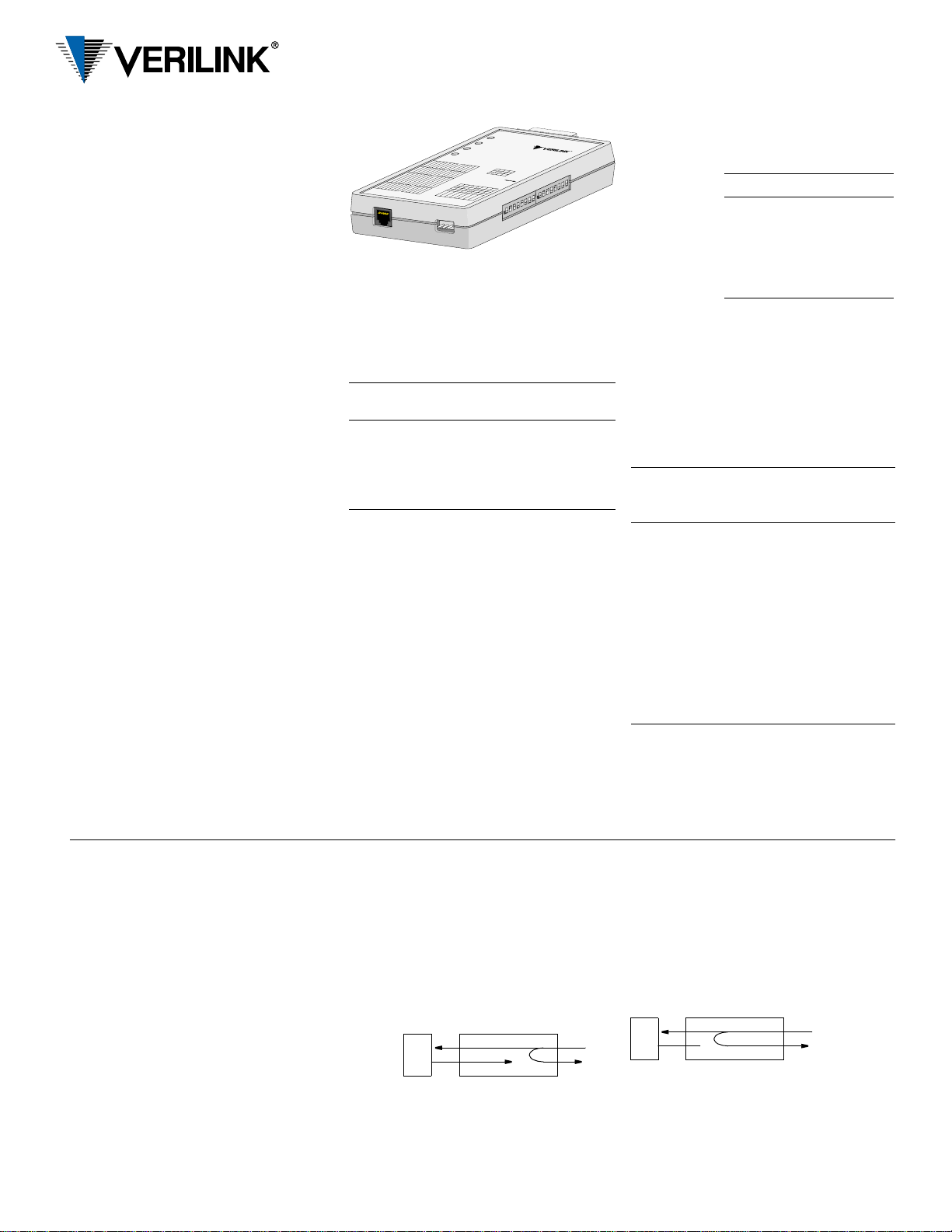
DDS Lite
Quick Start Guide
45-00150
2.0
Note: F o r more inf ormation about the DDS Lite,
see the reference manual, part number
34-00295, on the User Documentation CD or at
www.verilink.com.
Specifications
Network Interface
Line Rate: 2.4, 4.8, 9.6, 19.2, 28, 38.4,
56, and 64 kbps
Line Code: AMI
Line Impedance: Balanced 135 Ω
Input Signal: +1 to −40 dB (ALBO)
Output Signal: 3.0 V (± 15%) base-peak
into 135 Ω,
1.5 V (± 15%) at the 9.6
kbps line rate
Line Protection: 1000 V lightning, input /
output
Mechanical
Mounting: desktop or wall mount
Dimensions: 1.25" H, 3.50" W, 5.75" D
Weight: 1 pound
Pow er S o u rc e
External: Input: 115 VAC
Output: 9 VAC, 400 mA, min.
Industry Standards
FCC Compliance:Part 15 Cla ss A
Subpart B, Pa rt 68
U.S. Safety: UL 1950
Canadian Safety: CSA C22 .2 No. 950 - 95
Industry Canada: CS - 03 , Issue 8
Bellcore GR-1089-CORE
Environmental
Operating Temp: 0° to 50°C (32° to 122°F)
Storage Temp: −20° to 70°C
(−4° to 158°F)
Humidity: 95% max (non- condensing)
RS23
T
W
R
A
B
B
B
2
A
T
R
A
S
C
A
(
B
S
3
2
N
2-DCE
DDS Lite
)
2
C
S
N
A
3
2
N
5
4
5
4
N
E
T
x
D
A
T
A
R
x
D
A
T
A
L
P
T
E
S
T
E
D
B
L
E
T
B
R
A
E
S
I
V
D
D
N
E
I
C
N
R
C
2
B
N
S
.
2
S
-3
T
E
A
5
.
L
A
L
B
A
A
L
M
N
L
A
R
E
A
M
N
M
R
R
N
A
N
C
N
S
E
C
N
A
R
N
I
U
A
T
T
S
L
R
C
S
E
A
A
D
N
C
P
T
L
U
S
E
I
T
4
S
U
A
N
C
5
I
T
2
U
.
C
-
A
T
V
T
R
T
R
T
-
S
I
D
3
-
4
S
N
5
I
N
I
T
I
N
I
T
I
N
S
I
T
I
N
S
P
I
T
I
N
S
P
I
T
I
S
P
T
I
S
P
S
P
P
N
E
T
S
C
-
R
T
S
E
C
D
e
A
T
N
C
l
N
a
y
D
A
C
R
(
A
U
T
E
R
E
A
S
S
D
S
N
U
-
3
I
U
T
A
N
S
-
2
S
2
3
-
2
S
N
4
-
I
B
N
5
I
T
I
N
I
T
I
N
S
I
T
E
I
S
P
R
s
T
T
I
S
P
A
b
W
S
P
k
R
s
T
P
E
b
T
4
I
.
k
N
B
2
.
4
.
P
W
E
A
2
S
-
2
-
2
N
B
B
i
t
s
A
3
.
2
T
5
.
2
-
t
o
-
C
T
S
m
s
)
.
.
4
.
2
B
.
B
.
B
5
B
.
B
4
B
.
A
3
A
.
A
A
A
A
B
A
B
B
A
A
B
A
A
B
s
A
b
s
T
k
b
R
s
s
k
A
b
b
k
C
k
2
s
.
.
b
s
4
2
.
k
b
3
.
k
5
.
4
R
Pre-Installation Information
All direct connections to DDS lines must be
made using standard plugs and jacks.
Before connecting the unit, inform the
local telephone company of the following
information.
REN/
Port ID
2.4
4.8
9.6
38.4
56
64
SOC kbps
6.0 N 2.4
4.8
9.6
38.4
56
64
FIC USOC
04DU5-24
04DU5-48
RJ-48S
jack
04DU5-96
04DU5-38
04DU5-56
04DU5-64
Wallmount Installation
Using Screws
1 Select a place close to a 115 VAC outlet with
clearance for the signal and power cables.
The indicators and switches should be easily
accessible.
2 Vertically place two #6 screws 3-13⁄32
inches apart at the selected place. L eave the
screws out ab ou t an eighth of an inch.
3 Place the upright unit over the screws until
the holes engage and slide the unit down until it locks.
Connections
DDS Network Connection
The network
DDS facility
interface is
an RJ-48C
(8-pin) modular jack with the
following
pinout.
RS-232 Port Connection
The RS-232 connector is a standard DB-25 female, configured as a DCE port.
The RS-232 pin assignments are shown below.
Only circuits used by the unit are listed. All unbalanced bipolar inputs and outputs meet RS232C physical and electrical specifications. The
asynchronous mode is ITU V.22 compliant.
Circuit RS-232
101 1 Frame Ground Gnd
102 7 Signal Ground Gnd
103 2 Transmit Data In
104 3 Receive Data Out
105 4 Request To Send In
106 5 Clear To Send Ou t
107 6 Data Set Ready Out
109 8 Data Carrier Detect Out
114 15 Transmit Clock Out
115 17 Receive Clock Out
Power
Plug the connector from the power supply into
the unit. Plug the transformer into an appropriate outlet. This applies power to the unit.
Pin Assignment
1 Network Transmit Out
2 Network Transmit Out
3–6 Not Used
7 Network Data In
8 Network Data In
Signal Function
(Note: All other
pins are open.) DCE
Indicators
Network
This three-color indicator shows the receiver’s
operating status. Green indicates a signal at the
receiver (either customer data or zero suppression). Amber indicat e s signal is present, but received data is idle or out of service. Red
indicates an insufficient signal for the receiver
to operate properly.
Tx Data
This three-color indicator shows the status of
the transmitted data. Green indicates marks.
Red indicates spaces. Amber indicates alternate
marks and spaces.
Rx Data
This three-color indicator shows the status of
the received data. Green indicates marks. Red
indicates spaces. Amber indicate s al ternate
marks and spaces.
Loop Test
This indicator show the loop status of the unit.
Amber indicates the unit is in loop mode.
When the indicator is Off, the unit is not in
loopback.
Loopbacks
Channel Loop
This loop
is activated by
the reversal of the simplex, 20 mA sealing current. This is a unidirectional loop that ignores
the DSU transmit data and retransmits the received DDS data. Receive data is unaffected
and circuit CF is forced Off.
DTE
NET
Data Set Loop (Non-latching)
This loop is activated by the receipt of at least
four consecutive loo p c om m an ds an d r emains
looped as long as each thir d pattern byte is the
loop command. It returns to normal op eration
after at least four pattern bytes that are not the
loop command. This is a unidirectional loop
that retransmits the DSU received data on the
DSU transmit data. Receive data is unaffected
and circuit CF is Off.
DTE
NET
V.54 Channel Loop (Annex B: RDL)
This loop is activated by the receipt of the V.54
loop command. This loop is unidirectional and
returns the DSU receive data to the DSU transmit data, and subsequently the DDS transmit
data. Receive data is unaffected.
Page 2

Configuration
On power up, the unit configures to the hardware settings of option switches SW1 and
SW2. Changes to these settings take effect after
resetting the unit by removing and then reapplying power. The unit then cycles through its
LEDs and reads the new configuration.
These switches provide the following
configuration parameters.
Network Bit Rate Select
Positions SW1-1, SW1-2, and SW1-3 are
used to set the network bit rate. Refer to the table shown in the upper left of the figure to determine the switch settings for a particular bit
rate. R TS-to-CTS delays double when position
SW1-8 is in the B position.
V.54 Loop Operation
Position SW1-4 is used to enable or disable
V.54 loop operation.
Data Polarity
SW1-5 is used to determine whether data bits
are inverted. In the A position, marks equal
pulses. In the B position, spaces equal pulses.
Receipt of OOF, OOS, idle, or loop codes
forces the DSU data to all marks (A position)
or spaces (B position) .
Circuit Assurance
When SW1-6 is in position B, the status of CF
(receive line signal detector) and CA (request
to send) controls the output CB (clear to send).
If either CA or CF is Off, CB is Off. If CA and
CF are On, CB is On.
CTS Control
When SW1-7 is in position B, CTS is forced
On regardless of the RTS input status. In the A
position, the delays are determined by SW1-8.
RTS -t o -C TS Del ay
When SW1-8 is in the A position, the RTS-to-
CTS delay is as shown in the table shown in
the upper left of the figure. In the B position,
the delays double.
Synchronous/Asynchronous Data
When SW2-1 is in the A position, the unit operates in Synchronous mode. This switch must
be in position B for switches SW2-2 and SW2-
3 to function. When in position B, the unit operates in Asynchronous mode. In Asynchronous mode, data functions at 2.4, 4.8, 9.6, 19.2,
and 38.4 kbps.
Asynchronous Word Length
Switches SW2-2 and SW2- 3 are set to match
the number of bits that make in each word of
the asynchronous dat a. Refer to the table
shown in the upper right of the figure.
Signalling Rate Range
Switch SW2-4 is set to match the ranges provided by the service provider.
Not Used
Switches S2-5, S2-6, S2-7, and S2-8 are not
used.
Rate
(kbps)SW1-1SW1-2SW1-3
2.4 B B B 8.0
4.8 A B B 4.0
9.6 B A B 2.0
19.2 A A B 1.0
28.0 B B A 0.8
38.4 A B A 0.5
56.0 B A A 0.4
64.0 A A A 0.3
V.5 4 Lo op
B
A
2
Channel
Enabled
Bit Rate
V. 5 4 D i s a b l ed
* Asynchronous data
does not function at
28, 56, and 64 kbps.
RTS-to-CTS
Delay (ms)
Circuit Assurance On
Data Inverted
Data Normal
CTS Forced On
CTS Normal
Circuit Assurance Off
Bits SW2-2 SW2-3
8A B
9B B
10 A A
11 B A
RTS -t o -C T S D e l a y ×2
Asynchronous Data*
867
25431
Async
Word
Length
Synchronous Dat a
The symbol indicates that the
switch pointed to does not function
unless the oppo sit e e nd of the a rrow
RTS- to -CTS Delay Norma l
is in the po sition s hown. For
example, SW1-8 functions only
when SW1-7 is in the A position.
314
not used
Extended Range
(−2.5 to 2.3%)
5867
not used
Basic Range
(−2.5 to 1.0%)
Warranty
Verilink's product warranty covers repair or replacement of all equipment under normal use
for a five-year period from date of shipment.
Replacement prod ucts may be new or reconditioned. An y replac ed or r epaire d produc t or part
has a ninety (90) day warranty or the remainder
of the initial warranty period, whichever is
longer. Our in-house Repair Center services on
a standard 10-workday-turnaround basis.
Returning Products
A product must be assigned a R e turn Materials
Authorization (RMA) number before it is sent
to Verilink for repair. An RMA number is issued by Verilink Customer Service at (800)
926-0085, ext. 2282.
not used
not used
not used
145 Baytech Drive
San Jose, California 95134
not used
not used
not used
Technical As s i s t a n ce Center
127 Jetplex Circle
Madison, Alabama 35 758
(800) 837-4546
www.verilink.com
FAX-On- Demand
(800) 957-546 5
(800) 285-2755
 Loading...