

Page 1
Access System 2000
ConnecT 56K DSU User Manual
Part Number 896-502110-001-A
November 1993
Verilink Corporation
145 Baytech Drive
San Jose, California 95134
Page 2

Important Notice
Before performing any operat ions, PLEASE
READ AND UNDERSTAND ALL
INSTRUCTIONS IN THIS MANUAL.
ITC Helvetica and ITC Times / International
Typeface Corporatio n
Panasonic is a registered trademark of Panasonic
Corporation
WHEN YOU ARE FINISHED, PUT THIS
MANUAL IN A PROMINENT LOCATION; DO
NOT THROW THIS MANUAL AWAY, unless it
is being replaced by a corrected or updated
manual.
VERILINK CORPORATION DISTRIBUTES
THIS REFERENCE “AS IS” WITHOUT
WARRANTY OF ANY KIND, EITHER
LIMITED OR IMPLIED. Verilink Corporation
reserves the right to revise this publication from
time to time without notice. Some states or
jurisdictions do not al low disclaimer of ex press or
implied warranties in certain transactions;
therefore, this statement may not apply to you.
Copyright 1993 Verilink Corporation.
All Rights Reserved.
This reference was written, illustrated, and
produced using FrameMaker
publishing software and AutoCad 12
workstation
computer
design software, Sun IPX and IPC Workstations,
Sun Sparc Laser Printers, and the ITC Helvetica
and ITC Times families of typefaces.
Your right to copy Access System 2000 and this
manual is limited by copyright law. Making copies
of this reference, or any part thereof, without prior
written authorization from Verilink Corporation is
prohibited by law and constitutes a punishable
violation of the law
The following are trademarks or registered
trademarks of their respective companies or
organizations:
AutoCad 12 / Autodesk Corporation
Access System 2000, Access Manager 2000,
Advanced Programmable Architecture, and Craft
Interface / Verilink Corporation
Sun Microsystems, Open Windows, Sparc Printer,
IPX, IPC, and Sun Workstation / Sun
Microsystems, Inc.
FrameMaker and Frame Technology / Frame
Technology Corporation
FCC Warning Statement
The Federal Communications Commission (FCC)
Rules require that you be notified of the following:
This equipment generates, uses, and can radiate
radio frequency energy and, if not installed and
used in accordance with this reference, can cause
interference to radio communications.
This equipment has been tested and found to
comply within the limits for Class A devices
pursuant to Subpart J of Part 15 of the FCC rules,
which are designed to provide reasonable
protection against such interference when operated
in a commercial environment.
Operation of this equipment in a residential area is
likely to cause interference, in which case the
user(s) will be required to take whatever measures
(that can be) required to fix the interference at
their own expense.
Per FCC Part 68 requirements, the customer is
required to notify the Telephone Company prior to
disconnecting any CSU from the network
interface.
FrameMaker and Frame Technology / Frame
Technology Corporation
Page 3

Table of Contents
CHAPTER 1 - Introduction ................................................................................................1-1
Unit Overview ................................................................................................................... 1-1
ConnecT 56K DSU rear panel ............................................................................... 1-2
DDS Overvie ................................................................................................................... 1-4
Switched 56 overview ........................................................................................................ 1-5
CHAPTER 2 - Installation ..................................................................................................2-1
Unpack, inspect, power up ................................................................................................. 2-1
What Verilink shipments include ........................................................................... 2-1
What the customer provides ................................................................................... 2-1
Power up ................................................................................................................. 2-1
Connecting the cables ........................................................................................................ 2-3
Network interface connection ................................................................................ 2-3
DTE data connection ...................... .. ...................................................................... 2-3
Secondary channel connection ............................................................................... 2-6
Configuration ..................................................................................................................... 2-7
Configuration methods ...................................................................................................... 2-8
Front panel ............................................................................................................. 2-8
“AT” commands ..................................................................................................... 2 -8
V.25 bis commands ................................................................................................ 2-9
SDLC option character format ................................................................. 2-9
BI-Sync option character format ............................................................ 2-10
Asynchronous option character format ................ .................................. 2-10
Command descriptions .......................................................................... 2-11
The syntax and possible responses ........................................................ 2-12
Switched 56 operation .......................................................................................... 2-13
Remote commands ............................................................................................... 2-14
CHAPTER 3 - Operation ................ ........ ........ ....................................................................3-1
Understanding the keypad ................................................................................................. 3-1
Manual operation and button functions .................................................................. 3-2
Enter button ............................................................................................. 3-2
Cancel ...................................................................................................... 3-2
Up and down scroll .................................................................................. 3 -2
Numeric keypad ....................................................................................... 3-3
ConnecT 56K DSU User Manual i
Page 4

* (Shift) ..................................................................................................... 3-3
(Quick) # .................................................................................................. 3-3
Examples ................................................................................................................. 3-3
Menu structure .................................................................................................................... 3-5
The four opening menu functions ...........................................................................3-5
1=Status .................................................................................................... 3-5
2=Test ....................................................................................................... 3-5
3=Config ................................................................................................... 3- 5
4=Dial ....................................................................................................... 3-6
General operations and menus ........................................................................................... 3-7
General operation method ....................................................................................... 3-7
Menu map ...................................... ......................................................................... 3-7
1 = STATUS ....................................................................................................................... 3-9
Submenu items ........................................................................................................3-9
2 = TEST .......................................................................................................................... 3-11
1=Local Unit ......................................................................................................... 3-12
1 = DTE & LOOP (LL) ..........................................................................3-13
2 = LOOP ONLY (RT) .......................................................................... 3-15
3 = DTE ONLY ......................................................................................3-16
4 = DTE WITH TP .................................................................................3-17
5 = Test Pattern ....................................................................................... 3-19
6 = Self test ............................................................................................. 3-20
2=Remote unit ....................................................................................................... 3-20
1 = Exit Test and 2 = Display Status ......................................................3-22
3 = CONFIG .....................................................................................................................3-24
Operation .............................................................................................................. 3-24
1=Network Options ............................................................................................... 3-25
Submenu 1 loop rate ...............................................................................3-27
Submenu 2 network ................................................................................3-28
Submenu 3 remote configuration ...........................................................3-28
Submenu 4 network type ..................... ...................................................3-28
Submenu 5 clock source .........................................................................3-29
2 = DTE options .................................................................................................... 3-29
Menu map ............................................................................................... 3-30
Operation ................................................................................................ 3-30
Submenu 1 DTE rate ..............................................................................3-31
Submenu 2 connector type .....................................................................3-32
Submenu 3 data format ...........................................................................3-33
Submenu 4 DTE CMD option ................................................................3-34
Submenu 5 transmit clock ......................................................................3-34
Submenu 6 CS options ...........................................................................3-35
Submenu 7 anti -stream ..........................................................................3-37
ii ConnecT 56K DSU User Manual
Page 5

Submenu 8 CD options .......................................................................... 3-38
Submenu 9 TR Options .......................................................................... 3-39
Submenu A SR options .......................................................................... 3-40
Submenu B secondary rate .................................................................... 3-40
3=Test options ...................................................................................................... 3-41
Menu map .............................................................................................. 3-42
Operation ............................................................................................... 3-42
Submenu 1 test timeout .......................................................................... 3-42
Submenu 2 RDL select .......................................................................... 3-42
Submenu 3 EIA LLB select ................................................................... 3-43
Submenu 4 EIA RLB select ................................................................... 3-43
4 = Dial options .................................................................................................... 3-43
Menu map .............................................................................................. 3-44
Operation ............................................................................................... 3-44
Submenu 1 phone number ..................................................................... 3-44
Submenu 2 auto answer ......................................................................... 3-44
5 = Manual command ........................................................................................... 3-45
Operation ............................................................................................... 3-45
APPENDIX A - Reference ................................................................................................. A-1
Warranty and customer service ......................................................................................... A-1
Telephone company information ...................................................................................... A-2
AT commands ......................... .... .. .... .. .... .......................................................................... A-3
Configuration profiles ....................................................................................................... A-6
Figures .............................................................................................................................. A-8
ConnecT 56K DSU User Manual
iii
Page 6

iv ConnecT 56K DSU User Manual
Page 7

List of Figures
Figure 1-1 ConnecT 56K DSU Front View ................................................................................... 1-2
Figure 1-2 ConnecT 56K DSU Rear View .................................................................................... 1 -2
Figure 3-1 ConnecT 56K DSU Front View ................................................................................... 3-1
Figure 3-2 Status Display .............................................................................................................. 3-9
Figure 3-3 Complete Test Menu ................................................................................................. 3-11
Figure 3-4 Local Unit Menu ....................................................................................................... 3-12
Figure 3-5 Status Display ........................................................................................................... 3-14
Figure 3-6 Status Display ............................................................................................................ 3-16
Figure 3-7 Status Display ........................................................................................................... 3-17
Figure 3-8 DTE WITH TP MENU .............................................................................................. 3-18
Figure 3-9 Complete Configuration Menu .................................................................................. 3-25
Figure A-1 DTE and Loop Test Diagram ...................................................................................... A-8
Figure A-2 Loop Only Test Diagram ............................................................................................ A-9
Figure A-3 DTE Only Test Diagram ............................................................................................. A-9
Figure A-4 DTE With Test Pattern Diagram ............................................................................... A-10
Figure A-5 Test Pattern Only Diagram ....................................................................................... A-10
Figure A-6 DSU to Modem Interconnect Diagram .................................................................... A-11
Figure A-7 EIA 232 Connector for 56 KB/s and 64 KB/s Application ...................................... A-11
ConnecT 56K DSU User Manual v
Page 8

List of Figures
vi
ConnecT 56K DSU User Manual
Page 9

List of Tables
Table 1-1 LED Identification ....................................................................................................... 1-2
Table 1-2 Identification of Numbers ............................................................................................ 1-3
Table 2-1 Pin Assignments for TELCO Connector .................................................................... 2-3
Table 2-2 Pin Assignments for Primary RS-232 Connector ........................................................ 2-4
Table 2-3 Pin Assignments for Primary V.35 Connector ............................................................ 2-5
Table 2-4 Pin Assignments for Auxiliary RS-232 Connector ...................................................... 2-6
Table 3-1 Identification of Numbers ............................................................................................ 3-1
Table 3-2 LED Identification ....................................................................................................... 3-2
Table 3-3 Test Commands ........................................................................................................3-13
Table 3-4 Test Displays ............................................................................................................. 3-14
Table 3-5 Available Interface Leads ......................................................................................... 3-14
Table 3-6 Submenu Test Commands ........................................................................................ 3-15
Table 3-7 DTE With Test Pattern Commands .......................................................................... 3-18
Table 3-8 Test Displays ............................................................................................................. 3-22
Table 3-9 Available interface leads ........................................................................................... 3-22
Table 3-10 Configuration submenus ............................................................................................ 3-24
Table 3-11 Submenus of 3=Config .............................................................................................. 3-24
Table 3-12 Loop Rate Commands ............................................................................................... 3-27
Table 3-13 Network Address Commands .................................................................................... 3-28
Table 3-14 Remote Configuration Commands ............................................................................ 3-28
Table 3-15 Network Type Commands ........................................................................................ 3-29
Table 3-16 Clock Source Commands .......................................................................................... 3-29
Table 3-17 DTE Rate Commands ................................................................................................ 3-31
Table 3-18 Loop Rate of 56K ....................................................................................................... 3-31
Table 3-19 Connector Type Commands ..................................................................................... 3-32
Table 3-20 Data Format Commands ........................................................................................... 3-33
Table 3-21 DTE CMD Commands ............................................................................................. 3-34
Table 3-22 Transmit Clock Commands ...................................................................................... 3-35
Table 3-23 CS Options Commands ............................................................................................. 3-36
Table 3-24 Anti-Stream Commands ............................................................................................ 3-38
Table 3-25 CD Options Commands ............................................................................................ 3-39
Table 3-26 TR Options Commands ............................................................................................. 3-39
Table 3-27 SR Options Commands .............................................................................................. 3-40
Table 3-28 Secondary Rate Commands ....................................................................................... 3-41
ConnecT 56K DSU User Manual vii
Page 10

List of Tables
Table 3-29 RDL Select Commands ............................................................................................. 3-43
Table 3-30 EIA LLB Select Commands ......................................................................................3-43
Table 3-31 EIA RLB Select Commands ...................................................................................... 3-43
Table 3-32 Auto Answer Commands ........................................................................................... 3-44
Table 3-33 Manual Command Values for Profiles .......................................................................3-45
Table A-1 Telephone company information ................................................................................. A-2
Table A-2 AT Commands ............................................................................................................. A-3
Table A-3 Configuration Profiles ................................................................................................ A-6
viii
ConnecT 56K DSU User Manual
Page 11

Chapter
1 Introduction
Unit Overview
This chapter provides an overview of the Verilink ConnecT 56K DSU,
Digital Data Service (DDS), and Switched 56 service.
The stand-alone Verilink ConnecT 56K DSU provides a reliable, high
speed data connection from a customer’s Data Terminal Equipment
(DTE) through Digital Data Service (DDS) lines, DDS secondary channel
services (DDSII), or 4-wire Switched 56 Network (SW56) lines. The
ConnecT 56K DSU supports both synchronous and asynchronous data
communication over the DDS or SW56 networks.
There are three easy methods for configuration:
1. A front panel dial pad and a LCD display provides quick and easy
access to configuration menus.
2. “AT” commands or by V.25 bis commands inband.
3. Remotely located ConnecT 56K DSU units can be configured by
using the front panel, AT commands, o r V.25 bis.
The ConnecT 56K DSU provides both V.35 and RS-232 electrical and
physical DTE interfaces to accommodate a variety of applications. A
second RS-232 interface is provided if the unit is configured for use on
DDS with secondary channel services. The ConnecT 56K DSU is
compatible with AT&T Accunet and U.S. Sprint SW56 as well as
standard DDS or DDS II services. To insure a reliable connection on
those services, the unit features an extended receiver capability which
permits operation over long loops (3.4 miles or 5.5 km at 26 awg).
ConnecT 56K DSU User Manual 1-1
Page 12

Introduction
Figure 1-1 ConnecT 56K DSU Front View
ConnecT 56K DSU
ENTER
1
23
ConnecT 56K DSU rear panel
RS
CS
RD CD ALM TST
TD
CANCEL
45
78
*
0
6
9
#
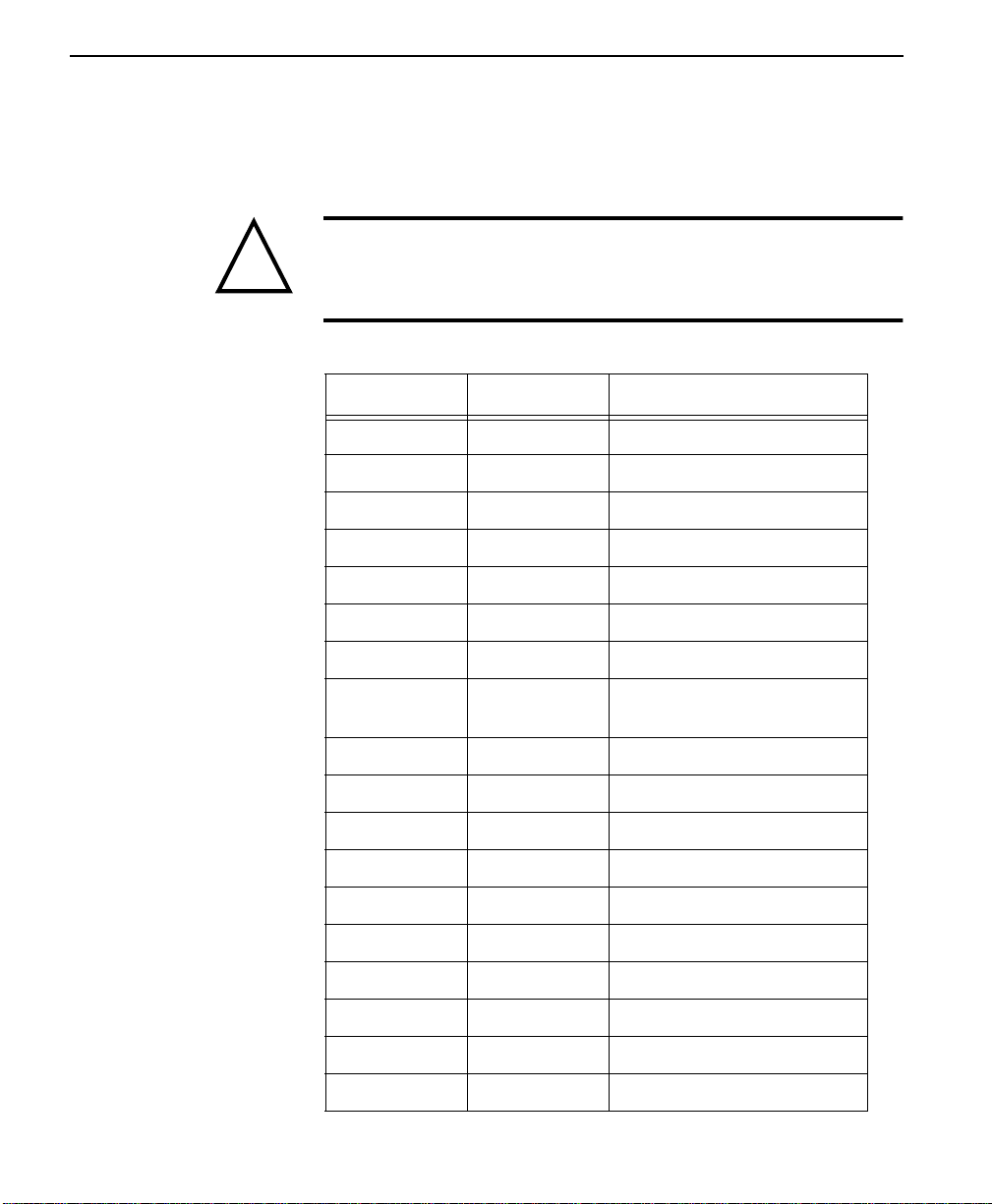
Table 1-1 LED Identification
RS Request to Send
CS Clear to Send
TD Transmit Data
RD Receive Data
CD Carrier Detect
ALM Alarm Indication
TST Test Mode
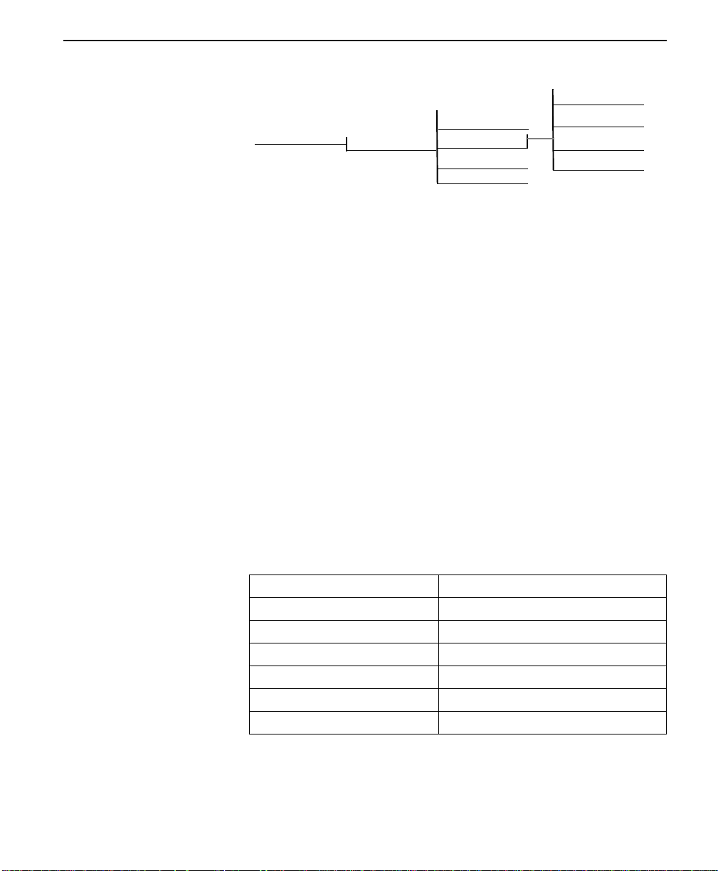
The rear panel contains three data DTE connectors which provide
primary channel V.35 or RS-232, and a secondary channel RS-232 port
(Auxiliary EIA 232). An 8-pin Telco jack, a captive power cord, and a
power switch are also located on the rear panel. Pin assignments for the
DTE and network connections are listed in Chapter 2.
1-2
Figure 1-2 ConnecT 56K DSU Rear View
TELCO
ConnecT 56K DSU User Manual
1
AUXILIARY EIA-232
PRIMARY EIA-232
3
4
PRIMARY V.35
R
FLB
V
B
B
N
Y
C
P
UTK
EJA
CD
A
MSH
WX
5
D
JNJDZ
L
F
F
HMH
C
EKKEA
L
MN
2
115 VAC
60HZ 15A
ON
OFF
6
Page 13

Unit Overview
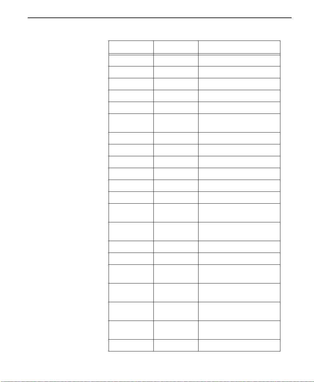
Table 1-2 Identification of Numbers
Item Function
1. Auxiliary EIA-232 Secondary channel services
2. Power Switch Used to turn power on or off.
3. Telco Connection to the Telephone
Company
4. Primary EIA-232 DTE interface
5. Primary V.35 High speed digital data interface
6. 115 VAC Connection Power cord connection
ConnecT 56K DSU User Manual
1-3
Page 14

Introduction
DDS Overview
Digital Data Service (DDS) is a nationwide service that allows
interconnection and transport of data at speeds up to 64 kB/s. The local
exchange carriers provide the local loop service to DDS customers and
may provide data for routing Inter-LATA to an interexchange carrier. In
DDS mode the ConnecT 56K DSU supports all DDS service rates
yielding DTE rates of 2.4, 4.8, 9.6, 19.2, 38.4 (sync or async) 56kbps and
64kbps. An additional rate of 57.6 kbps i s available in async mode. At the
service rate of 56k the unit can be configured to run slower DTE rates
(async or sync) over the 56kbps service. Secondary channel operation is
supported at all service rates up to 56K, providing terminal rates of 75,
150, 300, 600, 1200, and 2400 bps. The secondary rates available depend
on the service rate configured.
1-4
ConnecT 56K DSU User Manual
Page 15

Switched 56 overview
This dial-up 4-wire Digital Data Service allows customers to pay for data
connection only when the unit is active. The regional Operating
Companies provide the 4-wire local loop service to SW56 customers.
Switched 56 service is supplied by AT&T, U.S. Sprint and other
interexchange carriers. In SW56 mode the ConnecT 56K DSU supports
DTE rates of 2.4, 4.8, 9.6, 19.2, 38.4 (async or sync) and 56kbps (sync).
Additional DTE rate of 57.6kbps is available in async modes.
Switched 56 overview
ConnecT 56K DSU User Manual
1-5
Page 16

Introduction
1-6
ConnecT 56K DSU User Manual
Page 17

Chapter
2 Installation
This chapter explains how to install the ConnecT 56K DSU.
Unpack, inspect, power up
Carefully inspect the ConnecT 56K DSU for any shipping damages. If
damage is suspected, file a claim immediately with the carrier and then
contact Verilink Customer Service. If possible, keep the original shipping
container for use in shipp ing the ConnecT 56K DSU back for re pair or fo r
verification of damage during shipment.
What Ve rilink shipments include
What the customer provides
Power up
Verilink shipments include the following:
■ The ConnecT 56K DSU unit.
■ Two line interface cables:
• an 8-position/modular to 8-position modular
• an 8-position/modular to 8-position spade lug
■ The user guide.
The customer must provide the following:
■ DTE cable(s):
■ An RS-232 Interface Cable with standard 25-pin male D-type
connectors (Cannon or Cinch DB-1 9604-432) or V.35 cable.
Each DSU unit is provided with a captive eight-foot power cord,
terminated by a three-prong plug which connects to a grounded power
receptacle.
A telco connector is provided for interface to the network and two others
provide connection to the data terminal equipment (DTE).
ConnecT 56K DS User Manual 2-1
Page 18

Installation
!
CAUTION
Power to the DSU must be from a 115 VAC, 60Hz that is grounded.
2-2
ConnecT 56K DSU User Manual
Page 19

Connecting the cable
This section describes the following connections:
■ Network interface connection
■ DTE data connection
■ Secondary channel connection
Connecting the cables
Network interface connection
DTE data connection
The ConnecT 56K DSU has an eight-position modular jack labelled
“TELCO.” The connector is used for connecting to the network when the
unit is configured for either dedicated or switched operation. The pin-out
for the “TELCO” connector is listed in Table 2-1, “Pin Assignments for
TELCO Connector”.
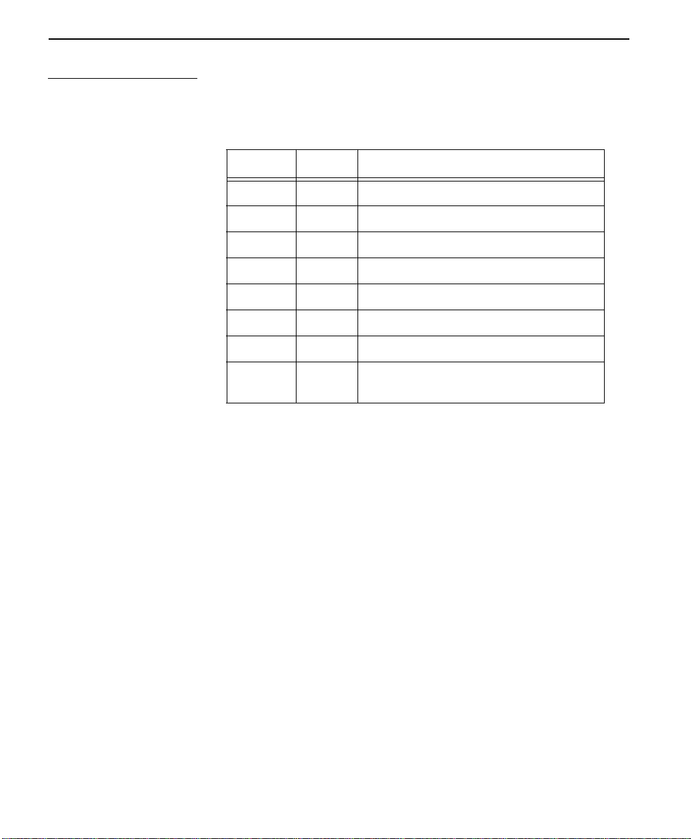
Table 2-1 Pin Assignments for TELCO Connector
Pin Name Description
1 R T ransmit Data (from DSU to
Network-Ring)
2 T Transmit Data (from DSU to
Network-Tip)
3-6 Not Used
7 T1 Receive Data (from Network
to DSU-Tip 1)
8 R1 Receive Data (from Network
to DSU-Ring 1)
The primary DTE should be connected to either the RS-232 DTE
connector or the CCITT V.35 DTE connector. The maximum cable
lengths recommended are 50 feet for the RS-232, and 100 feet for the
CCITT V.35. The pin assignments for the connectors are listed in
Table 2-2, “Pin Assignments for Primary RS-232 Connector” and
Table 2-3, “Pin Assignments for Primary V.35 Connector”.
The V.35 connector is recommended for use with data rates above
19.2kbps. The RS-232 connector will work up to 56kbps with a lo
capacitance cable or with the external transmit clock option selected. The
ConnecT 56K DS User Manual
2-3
Page 20
Installation
!
primary DTE rate is configured from the front panel. The PRIMARY
Data Terminal Equipment can operate in asynchronous or synchronous
modes.
CAUTION
To prevent possible Radio Frequency interference emissions, a
shielded V.35 Cable is required.
Table 2-2 Pin Assignments for Primary RS-232 Connector
Pin EIA Description
1 AA Protectiv e Gr ound (PG)
2 BA Transmit Data (SD)
3 BB Receive Data (RD)
4 CA Request To Send (RS)
5 CB Clear To Send (CS)
2-4
6 CC Data Set Ready (SR)
7 AB Signal Grou nd (SG)
8 CF Received Line Signal Detec-
tor (CD)
9 - +12 T est P oint
10 - -12 Test Point
15 DB Transmit Clock (TC)
17 DD Receive Clock (RC)
18 - Local Loopback (LL)
20 CD Data Terminal Ready (TR)
21 - Remote Loopback (RL)
22 CE Ring Indicator (RI)
24 DA External TX Clock (ETC)
25 - Test Indicator (TI)
ConnecT 56K DSU User Manual
Page 21
Connecting the cables
Table 2-3 Pin Assignments for Primary V.35 Connector
Pin CCITT Description
A 101 Protective Ground (PG)
B 102 Signal Ground (SG)
C 105 Request To Send (RTS)
D 106 Clear To Send (CTS)
E 107 Data Set Ready
F 109 Received Line Signal Detec-
tor (CD)
H - Data Terminal Ready (DTR)
J - Ring Indicator (RI)
L - Local Loopback (LL)
N - Remote Loopback (RL)
R 104 Received Data (RD-A)
T 104 Received Data (RD-B)
V 115 Receiver Signal Element Tim-
ing (SCR-A)
X 115 Receiver Signal Element Tim-
ing (SCR-B)
P 103 Transmitted Data (SD-A)
S 103 Transmitted Data (SD-B)
Y 114 Transmitter Signal Element
Timing (SCT-A
AA 114 Transmitter Signal Element
Timing (SCT-B
U 113 Extern al TX Signal Element
(SCX-A)
W 113 External TX Signal Element
(SCX-B)
NN - Test Indicator (TI)
ConnecT 56K DS User Manual
2-5
Page 22
Installation
Secondary channel connection
If used, the secondary data terminal equipment should be connected to the
Auxiliary EIA 232 connector. The pin-out for the connector is listed in
Table 2-4, “Pin Assignments for Auxiliary RS-232 Connector”.
Table 2-4 Pin Assignments for Auxiliary RS-232 Connector
Pin EIA Description
1 AA Protective Ground (PG)
2 BA Transmit Data (SD)
3 BB Receive Data (R D)
4 CA Request-to-Send (RS)
5 CB Clear-to-Send (CS)
6 CC Data Set Ready (SR)
7 AB Signal Ground (SG)
8 CF Received Line Signal Detector (CD).
Always on.
2-6
ConnecT 56K DSU User Manual
Page 23

Configuration
Configuration
The ConnecT 56K DSU contains four different user profiles (sets of
configurations options) listed in Appendix II, that are stored in read only
memory. The unit is shipped from the factory with profile 1 (default
configuration) loaded into the non-volatile configuration memory. If
profile 1 matches the desired system requirements, then no additional
configuration is required to put the unit into service. If profile 1 does not
match the desired system requirements, there are two options available.
1. Modify the default configuration.
2. Select one of the other profiles that more nearly matches the desired
configuration, modify to required specifications.
When a new profile is loaded, or the existing profile is modified, it is
stored in the non-volatile configuration memory. The ConnecT 56K DSU
is then configured with that profile every time power is turned on, or the
unit is reset.
ConnecT 56K DS User Manual
2-7
Page 24

Installation
Configuration methods
The ConnecT 56K DSU provides four different methods for local
configuration and three different methods for remote configuration:
1. Front Panel
2. AT Commands
3. V.25 bis
4. Remote Commands
Front panel
“AT” commands
The Front Panel provides access to all operation parameters of the
ConnecT 56K DSU through a multi-level menu structure which begins
with the four-part Main Menu. (See Chapter 3).
1=STATUS Displays status of network and DTE interface
2=TEST Controls local and remote testing
3=CONFIG Displays/changes current configuration parame-
ters
4=DIAL Provides manual dialing functions (a vailable only
when unit is configure d for SW56 operation).
In addition to the front panel, the ConnecT 56K DSU can be configured
and controlled with in-band AT commands from an asynchronous DTE
port just as modems are.
To exit the data mode and enter the command mode, the asynchronous
DTE device must transmit a proper escape sequence to the ConnecT 56K
DSU. A specified time delay must occur between the last data character
and the first escape sequence character. This is the guard time delay, and
it can be changed by writing a value to the S12 register. The default value
for the guard time is one second. For a valid escape sequence t o occur, the
DTE must transmit the escape code character three times in succession
with delay between each character being less than the guard time.
2-8
ConnecT 56K DSU User Manual
Page 25

Configuration methods
Once the command mode is entered, AT commands can be transmitted to
the ConnecT 56K DSU to configure most of the options, dial remote
DSUs, or initiate tests to check both the ConnecT 56K DSU and the
network connections. All command lines must begin with the AT
character set in either capital or lower case letters. A command line can
be terminated at any time by transmitting the CTRL-X (ASCII 018) after
the AT attention code. The ConnecT 56K DSU will ignore this command
line and issue an OK response.
The command line may contain a single command or a series of
commands after the AT attention code. When a series of commands is
used, the individual commands may be separated with spaces for
readability. The maximum length for a command line is 40 characters.
Each command line is executed by the ConnecT 56K DSU upon receipt
of a terminating character. The default terminating character is a carriage
return (ASCII 013), but it can be changed by writing a different value to
register S3.
Before the terminating character is transmitted, the command line can be
edited by using the backspace character (ASCII 008) to erase errors so the
proper commands can be entered. Valid AT commands for the ConnecT
56K DSU are listed in Appendix I.
V.25 bis commands
2. BI-SYNC
3. ASYNCHRONOUS.
2. Parity bit - IGNORED
When configured for the V.25 bis option, the ConnecT 56K DSU accepts
in-band dialing and configuration commands from both synchronous and
asynchronous DTE ports.
The V.25 bis option supports the following protocols:
1. SDLC
SDLC option character format
1. Data bits - 8
COMMAND STRUCTURE:
ConnecT 56K DS User Manual
2-9
Page 26

Installation
[F][A][C][V.25 bis COMMAND][FCS][F]
The address field [A] is FFH. The control field [C] is set to 13H except
for cases of multi-frame responses. For this case, t he contr ol field is set to
03H in all but the last frame. The 03H in the control field indicates that
other frames are to follow while the 13H in the control field indicates the
final frame.
BI-Sync option character format
1. Data bits - 7
2. Parity bit - OD
COMMAND STRUCTURE:
[SYN][SYN][STX][V.25 bis COMMAND][ETX]
Asynchronous option character format
1. Start bit - 1
2. Data bits - 7
3. Parity bit - EVEN
4. Stop bit - 1
COMMAND STRUCTURE:
[V.25 bis COMMAND][CR][LF]
2-10
ConnecT 56K DSU User Manual
Page 27

Configuration methods
Command descriptions
The Verilink V.25 bis command set is a subset of the CCITT V.25 bis
command set. In addition to the CCITT commands supported, Verilink
has added configuration commands for both the local and remote DSU’s.
The Verilink V.25 bis command set is:
CIC Connect Incoming Call
CNL CoNfiguration Local
CNR CoNfiguration Remote
CRN Call Request with Number
CRS Call Request using Stored number
DIC Disregard Incoming Call
PRN PRogram Number
RLN Request List of Numbers
Possible responses to V.25 bis commands are:
VALA Valid V.25 command processed
INV An Invalid command detected
CFIET Call failed on switched network - busy detected
CFIDE Call failed on switched network - no wink detected
CFINS Call failed - no dial string in specified register
INVCU Unknown command detected
INVPS Invalid parameter syntax
INVPV Invalid parameter value
INVBL Invalid local password
INVBM Invalid remote password
INC Incoming call
CNX Call connected
ConnecT 56K DS User Manual
2-11
Page 28

Installation
If verbose responses are disabled (ATV0), the 3 character responses listed
below are the only ones returned:
VAL Valid V.25 command pro-
cessed
INV Invalid command received
CFI Call failed
INC Incoming call
CNX Call connected
The syntax and possible responses
Following is a list of V.25 bis commands and their possible responses.
CIC Connect Incoming Call:
This command causes the DSU to go online. There are no parameters
associated with this command. Possible indications include: VALA,
CNX, CFIxx
2-12
CNL Local Configuration:
This command is used to pass AT commands to the local modem via the
V.25 bis command processor. This allows the ConnecT 56K DSU to be
configured with AT commands via a synchronous interface. The format
of this command is:
CNL[LOCAL PASSWORD];AT[ONE OR MORE AT COMMANDS]
The local password may or may not be required depending on the present
configuration of the unit. Responses to CNL commands are returned in
the data format currently configured. Possible responses include: VALA
and INVAn.
CNR Remote Configuration:
This command is used to pass AT commands over the network to the
remote DSU via the V.25 bis command processor. This allows a remote
ConnecT 56K DSU to be configured from a synchronous interface. The
format of CNR this command is:
CNR[REMOTE PASSWORD];AT[ONE OR MORE AT COMMANDS]
ConnecT 56K DSU User Manual
Page 29

Configuration methods
The remote password may or may not be required depending on the
present configuration of the remote unit. Responses to the CNR
commands are returned in the data format currently configured. Possible
responses include: VAL and INVAn.
Switched 56 operation
Following is a list of switched 5 6 commands and their poss ible respo nses.
CRN Call Request with Number:
When the ConnecT 56K DSU is configured for switched 56 operation,
the CRN command causes the DSU to dial the supplied number. The
format of the command is:
CRN [NUMBER TO BE DIALED]
If no number is included in the command, the number stored in dial
register number 1 is dialed. If no number is provided and no number is
stored in dial register number 1, the ConnecT 56K DSU responds with the
call failure indication CFINS (Call Failure Indication Not Stored).
CRS Call Request using Stored number:
The CRS command causes the ConnecT 56K DSU to dial the number
stored in the specified register. The format of this command is:
CRS [OPTIONAL SPACE][REGISTER NUMBER 1-10]
If this command is issued without the register number parameter, the
INVPS (INValid Parameter Syntax) response is issued. If this command
is issued and the register parameter is not in the valid range for dialing
registers, the INVPV (INValid Parameter Value) response is returned.
Other responses include: VAL, CNX, CFIxx
DIC Disregard Incoming Call:
This command causes the V.25 bis processor to return to command mode
even if there is an incoming call pending. This allows the user to issue
local commands and ignore the incoming calls. There are no parameters
associated with this command. Possible responses include: VAL.
PRN Program Number:
This command stores the supplied number into the specified register. The
format of this command is:
PRN [REGISTER NUMBER];[NUMBER TO BE STORED]
ConnecT 56K DS User Manual
2-13
Page 30

Installation
If this command is entered with no parameters, the INVPS response is
returned. If no register number is included in the command or if it is
invalid, the INVPV response is returned. If the number to be stored
contains invalid characters, the INVPV response is also returned. The
characters 1, 2, 3, 4, 5, 6, 7, 8, 9, 0,: P, T, and & are valid dial characters.
If no digits are issued with this command, the specified register is cleared.
Possible responses include: VAL.
RLN Request List of Numbers:
This command causes the ConnecT 56K DSU to return the number stored
in the specified register. The format of this command is:
RLN [REGISTER NUMBER]
If the register number is invalid, the INVPV response is returned. When a
correct register number is entered, the response is:
LSN [REGISTER NUMBER];[NUMBER STORED]VAL
If no register number is present in the command, the ConnecT 56K DSU
responds with a list of all the registers and the stored numbers. This list is
followed by the VAL response. Possible indications include: VAL.
Remote commands
2-14
ConnecT 56K DSU User Manual
Remote Configuration is available by attaching a remote device via the
Primary EIA-232 connection on the rear panel and setting the DSU to
accept Remote Configurations.
The 3=CONFIG menu is used to enable or disable the ConnecT 56K
DSU remote configuration capability. See Chapter 3, Menu 3=CONFIG.
Page 31

Chapter
3 Operation
This chapter describes the keypad, menu functions, and ConnecT 56K
DSU operation.
Understanding the keypad
Following is an illustration of the ConnecT 56K DSU keypad.
Figure 3-1 ConnecT 56K DSU Front View
1
2
RS
CS
RD CD ALM
TD
ConnecT 56K DSU
TST
ENTER
CANCEL
5
4
1
45
78
*
23
6
9
0
3
#
Table 3-1 Identification of Numbers
Item Description Function
1 LCD Window Displays menu items and messages in
2 lines by 16 characters.
2 ENTER Selects active menu items.
3 Numeric Keypad: Shift:
Numbers/Alpha characters ac tivat e
menu items. The Alpha ch ar act er s are
entered by pressing the shift key before
each desired cha rac ter.
Quick return to the 3 main menu
choices.
(Quick) / #
4 C A N C E L Exits submenus.
5 Up and Down Scroll
Changes display of menu items.
Arrows
ConnecT 56K DS User Manual 3-1
Page 32
Operation
Table 3-2 LED Identification
RS Request to Send
CS Clear to Send
TD Transmit Data
RD Receive Data
CD Carrier Detect
ALM A larm Indication
TST Test Mode
Manual operation and button functions
This section explains the use of buttons and manual operation.
Enter button
The Enter button is used to select menu items. For example, to select
menu Items press the Up or Down scroll buttons to display menu items.
When the desired menu item is displayed, press the number of the item to
activate (flashing). When the desired menu item is flashing, press the
Enter button. As a result, a submenu is invoked or a configuration
parameter is set. The display of “command accepted” indicates a valid
operation.
Cancel
Cancel the current activity, and return to the previous menu; repeat until
the desired menu level is displayed. For example, when t he Submenu
item is displayed. Press the cancel button resulting in the display
returning to the previous menu. Repeat until the desired menu level is
reached.
Up and d wn scroll
View all of the submenu selections available in the active menu. Submenu
items display two at a time and in a circular or wrapping fashion. When
the submenu items are scrolled, they will continuously appear from
beginning to end in a forward (down button) or reverse (up button)
pattern.
3-2
ConnecT 56K DSU User Manual
Page 33

Understanding the keypad
Note:
The active menu item or configuration parameter flashes.
Examples: 1. To view submenu items in a forward pattern:
When the menu is selected and the submenu items are displayed press the
down scroll button. When the end of the list is reached, pressing the down
scroll button again will continue the display of the same menu fro m the
beginning.
2. T o vi ew submenu items in a re ver se pattern: When the menu is selected
and the submenu items are displayed press the up scroll button When the
beginning of the list is reached, pressing the up scroll button again will
continue the display of the same menu from the end.
Numeric keypad
Numbers 0 through 9 and Alpha characters, A through F, are used for
activating menu items. Numbers 0 through 9 are used to enter parameters
settings.
* (Shift)
Alpha characters are activated by pressing the shift key before each alpha
keystroke.
Examples
(Quick) #
Quick return to the main menu choices.
Following are two examples:
EXAMPLE #1. To activate a menu item when menu selection is
known
, either by seeing in the display or remembered from use, press the
desired menu item number. The display will automatically update by
activating (flashing) the desired selection. Press Enter to complete the
selection. To use the alpha characters: Submenu 2=DTE Options,
submenu of 1=Local, submenu of 3=Configuration has more than 9
choices. Submenu items A and B must be selected with the * (Shift) key.
When the 2=DTE OPTIONS menu is flashing, press ENTER. Use the
scroll to display submenu item A or B. Press the * (shift) key then, press
ConnecT 56K DS User Manual
3-3
Page 34

Operation
the desired letter. If the letter is mistakenly pressed without using the *
key, the numbered item will become active. To correct, repeat the correct
procedure.
EXAMPLE #2. To enter a numeric entry, press the desired numbers at
the cursor position, followed by pressing ENTER.
3-4
ConnecT 56K DSU User Manual
Page 35

Menu structure
Menu structure
The ConnecT 56K DSU uses a multilevel menu approach to access its
many features. All menu operations are displayed in the LCD window.
The opening menu is the access point to all other operations. There are
three main menu items, 1=Status, 2=Test, 3=Configuration and an
optional fourth item, 4=Dial. The Dial menu is available only when
Accunet SW56 or US Sprint SW56 is selected as the Network Type from
the Network Opt., submenu of Configuration Main Menu.
Each Main Menu item has several f unctions and s ubmenus to id enti fy and
access specific parameters. In the discussions that follow each main menu
contains a menu diagram to identify the location of each operation.
LCD display of opening Menu:
1=STATUS 2=TEST
3=CONFIG 4=DIAL
The four opening menu functions
This section discusses the four opening menu options.
1=Status
Used to display all relevant information for the network and DTE
interfaces. Displays current Operating Data Mode, Loop Status, Rate of
service from the network, DTE Data Rate and Format and DTE Interface
Lead status. System will return to the Status display when idle.
2=Test
Used to control local and remote testing. Selects local or remote testing,
defines unit address for remote testing, and selects type of test and test
pattern when required.
3=Config
Used to select all desired network and DTE operating parameters. When
certain Loop Rates (64K or 56SC are selected, a scramble option
submenu is displayed in lieu of the DTE Rate menu to control
scrambling).
ConnecT 56K DS User Manual
3-5
Page 36

Operation
4=Dial
Provides manual dialing functions. This menu item is displayed and
available for use only when the Accunet SW56 or US Sprint SW56 is
selected as the Network Type from the Network Opt. Menu.
3-6
ConnecT 56K DSU User Manual
Page 37

General operations and menus
This section discusses general operations and menus for the ConnecT
56K DSU.
General operations and menus
General operation method
Following is a list of general operations and how to execute them.
Activate The initial pressing of any Number will “activate” (cause
to flash) that numbered menu item.
Display Use the up and down Scroll keys to display menu choices.
In this manual, choices are listed in order using the down
scroll button. When all menu items have been displayed,
continued pressing of the scroll button will repeat the
menu display list. Using the up scroll key will move
through selections in reverse order.
Select Pressing the Enter button will enter into use of the
activated menu item which will offer further choices. If
the activated item is a parameter choice, it will be entered
into the system. The message “Command Accepted” will
briefly display before returning to the currently active
menu/submenu item.
Abort To abort any operation, press the Cancel button or the #
(Quick), number symbol, button. The system will return
to the main m e nu.
Exit Menu flows end with the selection of a parameter and the
brief display of “Command Accepted” or other message,
after which the display will return to the active menu item.
Menu selection may resume o r usin g Cancel or # (Quick )
may be desired. If no further operation follows, the system
will return to the Status display.
Menu map
The operation of the ConnecT 56K DSU is accomplished via use of multi
level menus. The operation of each menu item will begin with a menu
map. Each identified selection of a menu is separated by a slash (/) mark.
For example the, Menu Map
3=Config/1=Local/3=Test Options/1=Test TIMEOUT/(Parameter)
would be operated by the following method:
ConnecT 56K DS User Manual
3-7
Page 38

Operation
From the opening Main Menu
1= STATUS 2=TEST
3= CONFIG 4=DIAL
press the number 3 to activate (begin flashing) 3=CONFIG.
When the menu 3=CONFIG is flashing, press the Enter button to select,
resulting in the displaying of two lines of submenu items.
1= LOCAL
2= REMOTE
Press the number 1 to activate (begin flashing) the Submenu 1= LOCAL.
Press Enter to select the activated submenu, resulting in the displaying of
two lines of submenu items.
1= NETWORK OPT.
2= DTE OPTIONS
Use the down scroll button to display menu items 3=TEST OPTIONS and
4=DIAL OPTIONS.
3= TEST OPTIONS
4= DIAL OPTIONS
3-8
Press the number 3 to activate the Submenu 3=TEST OPTIONS. Press
Enter to select the activated submenu resulting in the displaying of two
lines of submenu items.
1=TEST TIMEOUT
2=RDL EN/DIS
Press the number 1 to activate the Submenu TEST TIMEOUT resulting in
the displaying of system prompts to enter the desired parameters.
ENTER TIMEOUT
(0=OFF) : 1 SEC.
Use the number keys to enter the number of seconds desired for the
Timeout. Press Enter to configure this system parameter resulting in the
system responding with an acceptance or rejection of the command and
returning to the previous submenu.
ConnecT 56K DSU User Manual
Page 39

1 = STATUS
1 = STATUS
The Status Selection displays two lines at a time of the current
operational status of the network and the DTE interfaces. After 30
seconds of no front panel operation on the ConnecT 56K DSU, it
automatically reverts to the status display.
Figure 3-2 Status Display
DATA MODE
LOOP IS NORMAL
Submenu items
1= STATUS
LOOP 56K
DTE 56SYNC
SR
ON
LLB
OFF
TR
OFF
RLB
OFF
Following are the submenu items:
Data Mode
Loop is Normal:
Current operation mode of the ConnecT 56K DSU current status of the
network interface.
Loop X
DTE 56K Sync:
Indicates the rate of the service from the network. Indicates the DTE data
rate and format.
TR SR LLB RLB:
Off/On
Lists four of the DTE interface leads. State of the respective leads
displayed immediately above.
Operation:
Follow standard operating procedure.
ConnecT 56K DS User Manual
3-9
Page 40

Operation
To view additional information, press the Up or Down scroll key which
displays two new lines of information. To exit the Status menu, press the
Cancel key.
3-10
ConnecT 56K DSU User Manual
Page 41

2 = TEST
2 = TEST
The ConnecT 56K DSU is able to perform a variety of tests that allow
problems to specific components of the communications circuit to be
isolated and identified. These various test modes for the ConnecT 56K
DSU are initiated and terminated from either the front panel or from the
DTE interface. When operating in an asynchronous mode, AT commands
can be used to control the testing from the DTE interface. For
synchronous operation, V.25 bis commands can provide the test control.
The unit also responds to standard DDS network tests initiated from the
TELCO test centers. In addition it can run several tests such as local and
remote loopbacks to aid in problem isolation. There are six built in test
patterns that can be used with both local and remote loopbacks. See Test
Menu drawing on the following page.
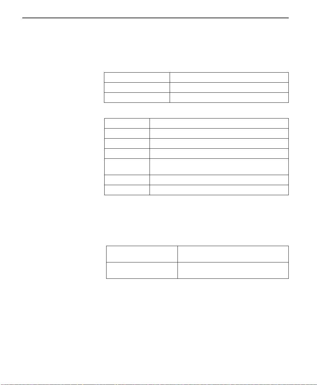
Figure 3-3 Complete Test Menu
1=DTE & LOOP (LL)
2=LOOP ONLY (RT)
3=DTE ONLY
4=DTE WITH TP
5=TE S T PATTER N
6=SELF TEST
ENTER TEST UNIT
ADDRESS: 00
2=TEST
1=LOCAL UNIT
2=REMOTE UNIT
1=EXIT TEST
2=DISPLAY STATUS
Menu flow is normally depicted from left to right. When scrolling
through submenu items with the down scroll button, the flow will wrap
from bottom to top and repeat the menu order. A “back up” can be
STATUS DISPLAYS
STATUS DISPLAYS
STATUS DISPLAYS
1=2047 P ATTERN
2=511 P ATTERN
3=STRESS PTRN #1
4=STRESS PTRN #2
5=STRESS PTRN #3
6=STRESS PTRN #4
1=204 7 PATTERN
2=511 PATTERN
3=STRESS PTRN #1
4=STRESS PTRN #2
5=STRESS PTRN #3
6=STRESS PTRN #4
SELF CHECK
CHECKSUM XXXX
SELF TEST
PASS
1=2047 PATTERN
2=51 1 PATT ERN
3=STRESS PTRN #1
4=STRESS PTRN #2
5=STRESS PTRN #3
6=STRESS PTRN #4
7=DATA FROM DT E
1=EXIT TEST
2=DISPLAY STATUS
1=EXIT TEST
2=DISPLAY STATUS
1=EXIT TEST
2=DISPLAY STATUS
STATUS DISPLAYS
STATUS DISPLAYS
STATUS DISPLAYS
1=EXIT TEST
2=DISPLAY STATUS
1=EXIT TEST
2=DISPLAY STATUS
1=EXIT TEST
2=DISPLAY STATUS
ConnecT 56K DS User Manual
3-11
Page 42

Operation
effected by using the up scroll button. At e very le vel of the menu pressing
the Cancel button will return to the previous menu level; used repeatedly
the system will return to the main menu.
1=Local Unit
Figure 3-4 Local Unit Menu
1=DTE & LOOP (LL)
2=LOOP ONLY (RT)
3=DTE ONLY
4=DTE WITH TP
1=LOCAL UNIT
5=TE S T PATTER N
6=SELF TEST
Note:
Shaded items are restricted to specific configurations or
operation.
The LOCAL UNIT selection is used to specify one of six different tests to
be performed by the local ConnecT 56K DSU. The selections are shown
as submenu selections 1 through six.
Displays
LOCAL DTE & LOOP
LOOP 56K
1=2047 P ATTERN
2=511 P ATTERN
3=STRESS PTRN #1
4=STRESS PTRN #2
5=STRESS PTRN #3
6=STRESS PTRN #4
1=204 7 PATTERN
2=511 PATTERN
3=STRESS PTRN #1
4=STRESS PTRN #2
5=STRESS PTRN #3
6=STRESS PTRN #4
SELF CHECK
CHECKSUM XXXX
SELF TEST
PASS
DTE 56K SYNC
SR
LLB
TR
OFF
OFF
LOOP 56K
SR
OFF
OFF
LOOP 56K
SR
OFF
OFF
OFF
LLB
OFF
LLB
OFF
UNIT IN TEST
LOOP IS NORMAL
DTE TEST
DTE 56K SYNC
TR
UNIT IN TEST
LOOP IS NORMAL
TEST P ATTERN
TST ERR=00
DTE 56K SYNC
TR
UNIT IN TEST
LOOP IS NORMAL
RLB
OFF
RLB
OFF
RLB
OFF
UNIT IN TEST
LOOP IS NORMAL
SR
OFF
LOOP 56K
LOOP 56K
SR
OFF
OFF
LLB
OFF
LLB
OFF
TR
OFF
DTE 56K SYNC
LOCAL LOOP (RT)
DTE WITH TP
TST ERR=00
DTE 56K SYNC
TR
UNIT IN TEST
LOOP IS NORMAL
RLB
OFF
RLB
OFF
3-12
Menu map
2=TEST/1=LOCAL UNIT
ConnecT 56K DSU User Manual
Page 43
2 = TEST
Operation
Follow standard operating procedure. When 2=TEST is flashing: Press
the Enter button resulting in the displaying of the first two submenu
items.
1=Local Unit
2=Remote Unit
Use the number 1 key to activate the 1=Local Unit Test submenu press the
Enter key to enter the submenu resulting in the displaying of two
submenu choi ces.
Table 3-3 Test Commands
Front Panel AT Command Description
1=DTE & LOOP (LL) &T10 TD/RD and RX/TX Loopbacks
2=LOOP ONLY (RT) &T11 RX/TX Loopback with DTE
3=DTE ONLY &T1 TX/RX Loopback at network
4=DTE WITH TP &T8 TX/RX Loopback with test pattern
5=TEST P ATTERN &T9 T ransmit/receive test pattern
6=SELF TEST NA Check internal components
interface
interface
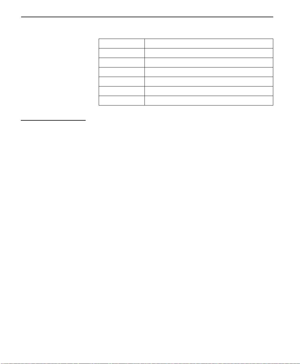
1 = DTE & LOOP (LL)
The DTE and LOOP test splits the ConnecT 56K DSU into separate DTE
and loop interface sections and then loops the receive data of each
interface back to its respective transmit data. A block diagram illustrating
the loopback points and the signal paths for this test is shown in
Table A-1, “DTE and Loop Test Diagram,” on page A -8.
When the LL lead from the DTE is activated, the test described above is
also performed by the ConnecT 56K DSU. The ConnecT 56K DSU
acknowledges this DTE activated test by activating the TM on the DTE
interface.
This particular test permits the separate sections of the ConnecT 56K
DSU to be checked. First, it allows the local DTE interface drivers and
receivers to be tested with an external data analyzer or data from the DTE
device. Second, it allows the loop interface section of the local DSU to be
tested from the remote site over the actual communications circuit.
ConnecT 56K DS User Manual
3-13
Page 44

Operation
Testing from the remote end of the circuit is normally done with a bit
error rate tester (BERT) or, by using an internal Test Pattern Generator on
the Remote DSU Unit.
Figure 3-5 Status Display
DTE & LOOP
LOOP 56K
DTE 56K SYNC
SR
1=DTE & LOOP (LL)
TR
OFF
UNIT IN TEST
LOOP IS NORMAL
OFF
LLB
OFF
RLB
OFF
Menu map
2=TEST/1= LOCAL UNIT /1=DTE & LOOP(LL)/Displays
Operation
Follow standard operating procedures. When 1=DTE & LOOP (LL) is
flashing: Press the Enter button to initiate the test resulting in the system
briefly displaying “Please Wait” after which it displays the type of test
being performed.
DTE & LOOP
3-14
Use the scroll buttons to continue viewing the other test results.
Table 3-4 Test Displays
DTE & Loop Type of test being performed
Loop 56K Loop rate
DTE 56K Sync DTE rate and data type
Table 3-5 Available Interface Leads
TR Terminal Ready Input
SR Set Ready Output
LLB Local Loopback Input
RLB Remote Loopback Input
OFF/ON State of the respective lead s displayed immediately
above.
Unit in Test Operating mode to ConnecT 56K DSU
Loop is Normal Status of network service
ConnecT 56K DSU User Manual
Page 45

2 = TEST
To Exit a Test press the Quick # key to access the 1=EXIT TEST/
2=DISPLAY STATUS submenu or press the Cancel key to change from
the status display to the main menu resulting in the TEST selection being
active (flashing). Press the Enter key resulting in the alternate test control
menu being displayed.
1=EXIT TEST
2=DISPLAY STATUS
1=EXIT TEST Terminates the test in progress and returns
2=DISPLAY STATUS Re-enters test display for additional viewing.
Table 3-6 Submenu Test Commands
Front Panel AT Command Description
1=EXIT TEST &T0 Stops test/returns to da ta mode.
2=DISPLAY STATUS NA Displays present test status
the ConnecT 56K DSU to the main menu.
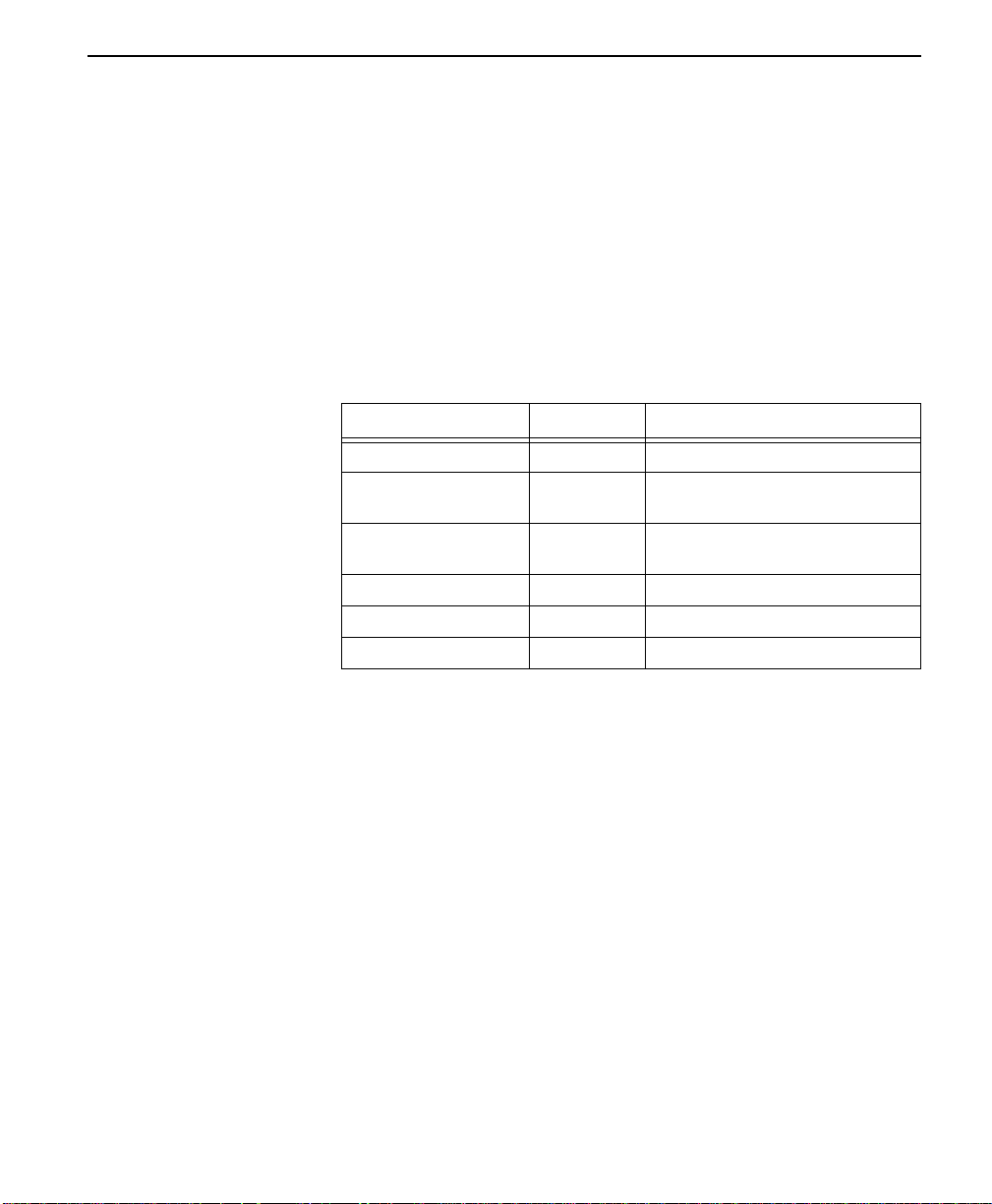
2 = LOOP ONLY (RT)
With the LOOP ONLY (RT) test, the network receive data is looped to the
network transmit Path inside the DTE interface section of the ConnecT
56K DSU. The physical DTE interface is ignored for this test. A block
diagram illustrating the loopback point and the signal paths for this test is
shown in Table A-2, “Loop Only Test Diagram,” on page A -9.
This test allows the loop interface and a major portion of the DTE
interface for the local ConnecT 56K DSU to be tested from the remote
site over the actual communications circuit. Like the DTE and LOOP
(LL) test, the test from the remote site is usually done with a BERT tester.
While this test is being performed, the message, LOCAL LOOP (RT), is
shown on the ConnecT 56K DSU display. The other status messages
shown in the menu drawing are accessible by using the UP/DOWN
SCROLL keys.
The loopback point within the ConnecT 56K DSU and its operation for
LOOP ONLY (RT) test are the same as the Remote Digital Loopback
(RT) test initiated and controlled from a remote DSU.
ConnecT 56K DS User Manual
3-15
Page 46

Operation
Figure 3-6 Status Display
UNIT IN TEST
LOOP IS NORMAL
SR
LLB
2=LOOP ONLY (RT)
TR
OFF
OFF
LOOP 56K
DTE 56K SYNC
LOCAL LOOP (RT)
OFF
RLB
OFF
Menu map
2=TEST/1= LOCAL UNIT/2=LOOP ONLY (RT)/Displays
Operation
Follow standard operating procedures. When 2=LOOP ONLY (RT) is
flashing: Press the Enter button resulting in the system briefly displaying
“Please Wait” after which it displays the first of the test results.
LOCAL LOOP (RT)
Continue with operational procedures described for DTE & LOOP (LL).
3-16
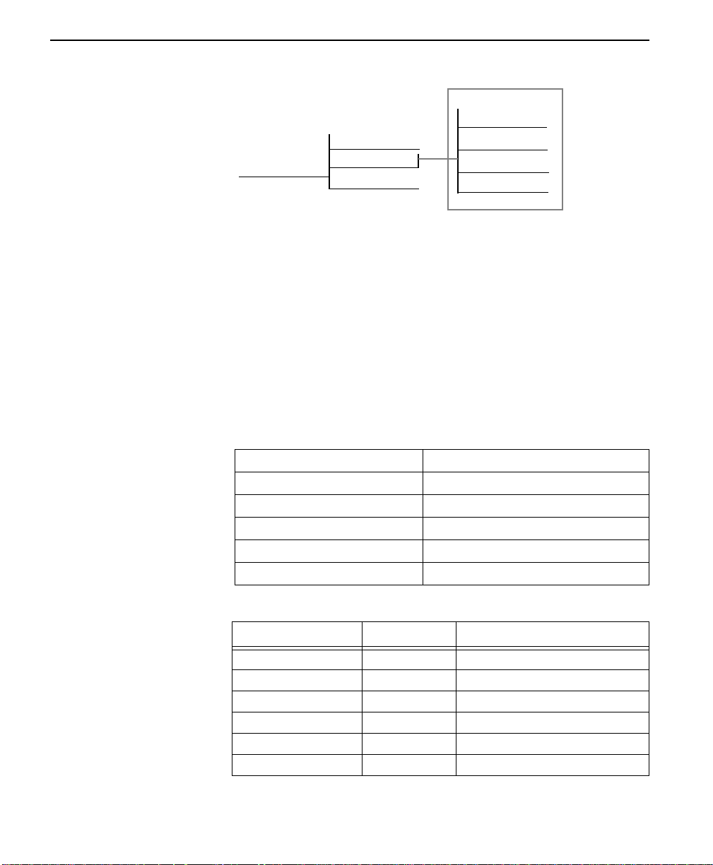
3 = DTE ONLY
The DTE ON LY test pr ovides a method for testing both the DTE interface
drivers and receivers of the local ConnecT 56K DSU plus its loop
transmitter and receiver. For this test, the loop transmit data is connected
to the loop receive data at a point close to the physical network interface.
The data is then sent back towards the DTE. The transmit circuit to the
network is terminated in a zero condition for this test. A block dia gram
illustrating the loop back point and the signal paths for this test is shown
in Table A-3, “DTE Only Test Diagram,” on pageA-9.
Test patterns from an external BERT tester are routed through the DTE
interface section of the ConnecT 56K DSU and then to the output of the
loop transmitter section where the signal is encoded for transmission.
Instead of being coupled onto the physical transmit circuit of th e network,
the output of the loop transmitter is coupled back to the loop receiver
input where the signal is then decoded and returned to the BERT tester
where the serial receive data stream is checked for any bit errors.
This test is used to verify proper operation of both the DTE and loop
interface sections of the local ConnecT 56K DSU.
ConnecT 56K DSU User Manual
Page 47

2 = TEST
Figure 3-7 Status Display
DTE TEST
LOOP 56K
DTE 56K SYNC
3=DTE ONLY
SR
OFF
OFF
LLB
OFF
TR
UNIT IN TEST
LOOP IS NORMAL
RLB
OFF
Menu map
2=TEST/1= LOCAL UNIT/3=DTE ONLY/Displays
Operation
Follow standard operat i ng procedures. When 3=DTE Only is flashing :
Press the Enter button resulting in the system briefly displaying “Please
Wait” after which it displays the first of the test results.
DTE TEST
Continue with operational procedures described for DTE & LOOP (LL).
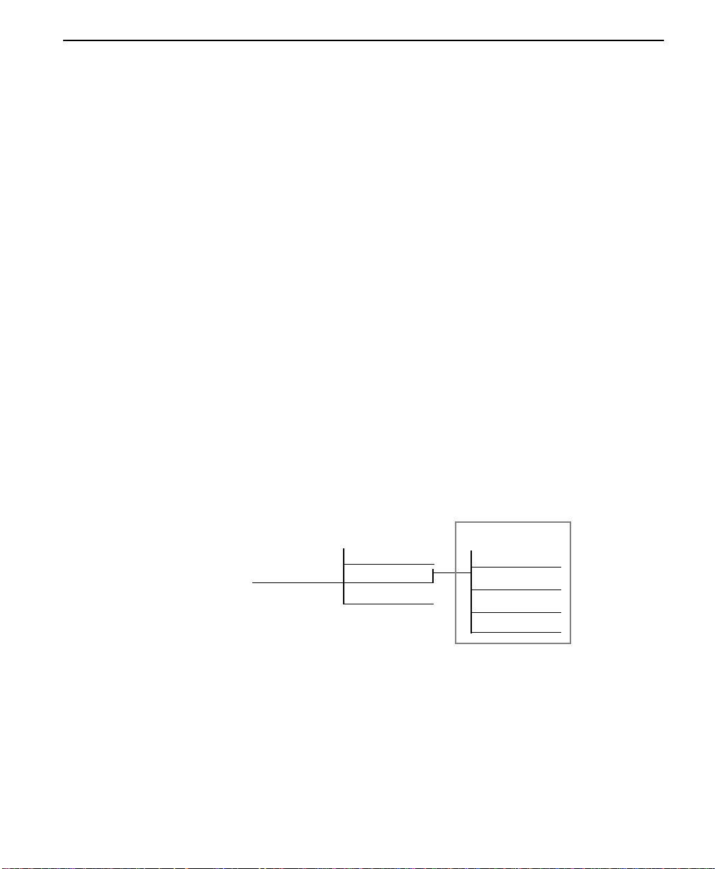
4 = DTE WITH TP
The DTE WITH TP (test pattern) test is similar to the DTE ONLY test
described above. Instead of using an external BERT tester connected to
the DTE interface, this test uses the internal test pattern generator and
detector built into the ConnecT 56K DSU. The loopback point and the
data paths for this test are illustrated in Tab leA-4, “DTE With Test
Pattern Diagram,” on page A-10. This test is primarily used to test the
transmitter and receiver sections of the local ConnecT 56K DSU.
The internal test pattern generator and detector of the ConnecT 56K DSU
operate with one of six different data patterns. When DTE WITH TP test
is selected, the particular test pattern to be transmitted by the generator
must also be selected. When a selection is made, the test pattern detector
examines the receive data stream until synchronization to the specified
pattern is achieved. Once synchronized, the detector continues to check
the receive data and reports any bit errors detected.
ConnecT 56K DS User Manual
3-17
Page 48
Operation
Figure 3-8 DTE WITH TP MENU
Displays
DTE WITH TP
TST ERR=00
LOOP 56K
DTE 56K SYNC
SR
OFF
LLB
OFF
TR
OFF
UNIT IN TEST
LOOP IS NORMAL
RLB
OFF
4=DTE WITH TP
1=2047 PATTERN
2=511 PATTERN
3=STRESS PTRN #1
4=STRESS PTRN #2
5=STRESS PTRN #3
6=STRESS PTRN #4
Menu map
2=TEST/1= LOCAL UNIT/4=DTE WITH TP/Submenus 1-6/Displays
Operation
Follow standard operating procedures. When 4=DTE With TP is flashing:
Press the Enter button resulting in the system briefly displaying “Please
Wait” after which it displays the first of the test results.
1=2047 PATTERN
2=511 PATTERN
Continue with operational procedures described for DTE & Loop (LL).
3-18
1=2047 Pa ttern Selects the 2047 Pattern
2=511 Pattern Selects the 511 Pattern
3=Stress Pattern #1 Selects DDS Stress Pattern 1
4=Stress Pattern #2 Selects DDS Stress Pattern 2
5=Stress Pattern #3 Selects DDS Stress Pattern 3
6=Stress Pattern #4 Selects DDS Stress Pattern 4
Table 3-7 DTE With Test Pattern Commands
Front Panel AT Command Description
1=EXIT TEST _T0 Standard 2047 random data pattern
2=DISPLAY STATUS _T1 Standard 511 random data pattern
3=STRESS PTRN #1 _T2 DDS stress pattern #1
4=STRESS PTRN #2 _T3 DDS stress pattern #2
5=STRESS PTRN #3 _T4 DDS stress pattern #3
6=STRESS PTRN #4 _T5 DDS stress pattern #4
ConnecT 56K DSU User Manual
Page 49
2 = TEST
While this test is being performed, the ConnecT 56K DSU displays:
DTE WITH TP TEST ERR=XX
The first line of the display indicates the type of test being performed
while the second line of the display indicates the number of errors
accumulated by the test pattern detector.
If errors occur during this test, the TEST ERR display can be reset to
zero, by pressing the “1” key. To verify proper operation of this test,
single bit errors can be injected into the transmitted test pattern by
pressing the “2” ke y. These errors will appear on the TEST ERR displa .
5 = Test Pattern
The TEST PATTERN selection actually converts the local ConnecT 56
DSU into a BERT tester for use in testing a remote DSU over the actual
communications circuit. With this test the remote DSU can be looped
back in either the DTE and LOOP (LL) or the LOOP ONLY (RT) mode.
Instead of being looped back the remote DSU can operate in the data
mode with data supplied from an external BERT tester, or it can be
operating in the TEST PATTERN mode. The data paths for this mode are
illustrated in Table A-5, “Test Pattern Only Diagram,” on page A-10.
When this test selection is chosen the system presents the same test
patterns as for DTE With TP.
Displays
5=TE S T PATTER N
1=204 7 PATTERN
2=511 PATTERN
3=STRESS PTRN #1
4=STRESS PTRN #2
5=STRESS PTRN #3
6=STRESS PTRN #4
TEST P ATTERN
TST ERR=00
LOOP 56K
DTE 56K SYNC
SR
OFF
LLB
OFF
TR
OFF
UNIT IN TEST
LOOP IS NORMAL
RLB
OFF
Menu map
2=TEST/1= LOCAL UNIT/5=TEST PATTERN/Submenus 1-6/Displays
Operation
Follow standard operating procedures. When 5=TEST PATTERN is
flashing: Press the Enter button resulting in the system briefly displaying
“Please Wait” after which it displays the first of the test results.
ConnecT 56K DS User Manual
3-19
Page 50

Operation
1=2047 PATTERN
2= 511 PATTERN
Continue with operational procedures described for DTE & Loop (LL).
6 = Self test
The Self Test is set designed to verify current operation of the ConnecT
56K DSU. It can be performed at any time and is recommended if there is
any question about the current DSU health.
SELF CHECK
6=SELF TEST
CHECKSUM XXXX
SELF TEST
PASS
Menu map
2=TEST/1= LOCAL UNIT/6=SELF TEST
Operation
Follow standard operating procedures. When 6=Self Test is flashing:
Press the Enter button resulting in the LEDs being active as the system
runs the self test, displays the results, and then returns to the Main Menu
display.
2=Remote unit
3-20
ConnecT 56K DSU User Manual
SELF TEST
CHECKSUM XXXX
Self Test Pass = indicates no problem with the operation. Self Test
Checksum XXXX = the software version.
The Remote Unit submenu allows the placement of a remotely installed
DSU into Loopback. This also applies to DSUs installed in a multi-point
network. After placing the remote DSU into loop a choice of 6 Test
Patterns or Data from the DTE may be selected. Test pattern results are
then displayed.
Page 51
2 = TEST
REMOTE WITH TP
TST ERR=00
LOOP 56K
DTE 56K SYNC
SR LLB RLB
TR
OFF OFF
OFF
OFF
UNIT IN TEST
LOOP IS NORMAL
2=REMOTE UNIT
ENTER TEST UNIT
ADDRESS: 00
1=2047 PATTERN
2=511 PATTERN
3=STRESS PTRN #1
4=STRESS PTRN #2
5=STRESS PTRN #3
6=STRESS PTRN #4
7=DATA FROM DT E
Menu map
2=Test/2=Remote Unit/Selections
Operation
Follow standard operating procedures. When 2=Remote Unit is flashing,
press the Enter button resulting in the displaying of the prompt to enter
the Test Unit Address.
Enter Test Unit
Address:XX
Use the number keys to type the address of Remote DSU press the Enter
key to enter the address into the system resulting in the displaying of the
first of the submenu items.
1=2047 Pattern
2=511 Pattern
Continue with standard operating procedures to select menu options. At
the end of the options the system will briefly display “Command
accepted” and return to the status menu.
1=2047 Pa ttern Selects the 2047 Pattern
2=511 Pattern Selects the 511 Pattern
3=Stress Pattern #1 Selects DDS Stress Pattern 1
4=Stress Pattern #2 Selects DDS Stress Pattern 2
5=Stress Pattern #3 Selects DDS Stress Pattern 3
6=Stress Pattern #4 Selects DDS Stress Pattern 4
7=Data From DTE
ConnecT 56K DS User Manual
3-21
Page 52
Operation
Status Displays
Remote With TP
TEST Err - 00
Table 3-8 Test Displays
Local DTE & Loop Type of test being performed
Loop 56K Loop rate
DTE 56K Sync DTE rate and data type
Table 3-9 Available interface leads
TR Terminal Ready Input
SR Set Ready Output
LLB Local Loopback Input
RLB Remote Loopback Input
OFF/ON State of the respective lead s displayed immediately
above.
Unit in Test Operating mode to ConnecT 56K DSU
Loop is Normal Status of network service
3-22
1 = Exit Test and 2 = Display Status
The menu choices here are used to immediately exit the test selection or
to re-enter status display. These menu items are available only after tests
have been performed.
1=EXIT TEST Will effectively exit the testing process
returning to the Main Menu for selection.
2=DISPLAY STATUS Re-enters test display for additional
viewing.
When a test has been requested, the system briefly displays “Please Wait”
before presenting the first test display. At any test result display: Press the
Quick # key to access the 1=EXIT TEST/2=DISPLAY STATUS submenu
or press the Cancel key to change from the status display to the main
menu resulting in the TEST selection being active (flashing).
ConnecT 56K DSU User Manual
Page 53

1=LOCAL UNIT
2=TEST
2=REMOTE UNIT
1=EXIT TEST
2=DISPLAY ST ATUS
Menu map
2=TEST/1=LOCAL UNIT or
REMOTE UNIT/Tests/1=EXIT TEST or
2=DISPLAY STATUS
2 = TEST
Note:
Shaded items are restricted to specific config u rations or
operation.
Press the Enter key resulting in the alternate test control menu being
displayed.
1=EXIT TEST
2=DISPLAY STATUS
1=Exit Test Terminates the test in progress and
2=Display Status Re-enters test di splay for additi onal
returns the ConnecT 56K DSU to the data
mode.
viewing.
ConnecT 56K DS User Manual
3-23
Page 54
Operation
3 = CONFIG
The Configuration menu consists of a group of five sub-menus relati ng to
a specific interface or function of the ConnecT 56K DSU that requires set
up.
T able 3-10 Configuration submenus
1=Network Opt. Network Interface Parameters
2=DTE Options DTE Interface Parameters
3=Test Options Unit Test Options
4=Dial Options Unit Dialing Options
5=Manual Command
The ConnecT 56K DSU contains four different user profiles (sets of
configurations options) that are stored in rea d only memory. The unit is
shipped from the factory with profile number 1 (default configuration)
loaded into the current (non-volatile configuration) memory. If profile 1
matches requirements for the system, then no additional configuration is
required to put the unit into service. If profile 1 does not match system
requirements, it can be modified, or one of the other profiles that more
closely matches the system requirements can be loaded into current
memory. When a different profile is loaded, or the existing profile is
modified, it is stored in the current (non-volatile configuration) memory.
The ConnecT 56K DSU is then configured with that profile every time
power is turned on or until the unit is reset.
Operation
3-24
ConnecT 56K DSU User Manual
See Configuration drawing on the following page.
Table 3-11 Submenus of 3=Config
1= LOCAL Configuration submenus are available to set all
the configuratio n paramet ers by manual operation
of the front panel.
2= REMOTE Establishes communication with the remote DSU
so the front panel of t he local DSU c an be used to
configure the remote DSU
Follow standard operating procedures. When 3=CONFIG is flashing.
Page 55

3 = CONFIG
Figure 3-9 Complete Configuration Menu
See Additional
Submenu Items 1-5
Submenu 4 is
Path to Enabling
Main Menu 4=Dial
See Additional
Submenu Items 1-9, A-B
See Additional
Submenu Items 1-4
1=PHONE NUMBER
2=AUTO ANSWER
3=CONFIG
1=LOCAL
2=REMOTE
ENTER
1=NETWORK OPT.
2=DTE OPTIONS
3=TEST OPTIONS
4=DIAL OPTIONS
ADDRESS
5=MANUAL COMMAND
Menu flow is normally depicted from left to right. When scrolling
through submenu items with the down scroll buttons, the flow will wrap
from bottom to top and repeat the menu order. A “back up” can be
effected by using the up scroll b utton. A t eve ry le vel of the menu pressing
the Cancel button will return to the previous menu level; used repeatedly
the system will return to the main menu.
Press the Enter button to enter the Configuration mode. This results in
displaying the two submenu choices:
1=LOCAL
2=REMOTE
1=Network Options
Use the “1” number to activate the 1=Local Menu. Press the Enter key to
enter the Local submenus. This displays the first two submenu choices.:
1=Network Opt
2=DTE Options
Offers the choices of the configuration parameters that control the loop
operation of the ConnecT 56K DSU.
ConnecT 56K DS User Manual
3-25
Page 56
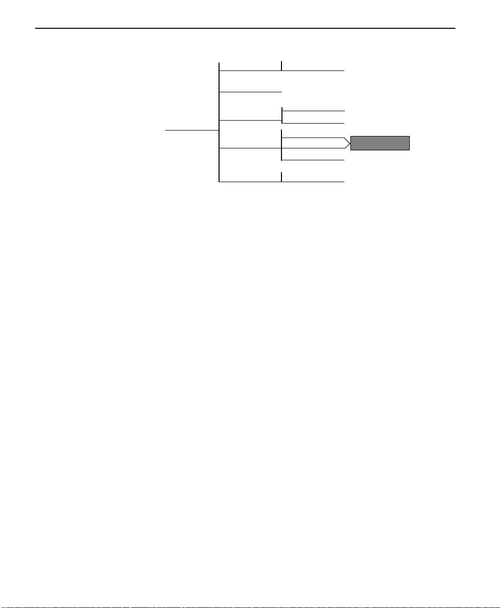
Operation
1=LOOP RATE
2=NETWORK ADDR.
3=REMOTE CONFIG.
1=NETWORK OPT.
4=NETWORK TYPE
5=CLOCK SOURCE
8 Choices
DISABLE
ENABLE
1=DDS
2=ACCUNET SW56
3=US SPRINT SW56
2 Choices
Enables Main
Menu 4=Dial
Menu map
3=CONFIG/1=LOCAL/1=NETWORK OPT.
Operation
Follow standard operating procedures. When 1=NETWORK OPT. is
flashing, press the Enter button. This displays the first of the submenu
items.
1=LOOP RATE
2=NETWORK ADDR.
Continue with standard operating procedures to select menu options. At
the end of the options the system will briefly display “Command
Accepted” and return to the active menu.
3-26
Non-standard operation
If submenu 1 or 8 is selected the system will briefly display “Command
Accepted” and return to the active Loop Rate menu. If any submenu 2
through 7 is selected the system will prompt for a selection of:
1=No Second Channel
2=Second Channel.
If this option is presented, continue the same operation to arrive at the
display of “Command Accepted.”
ConnecT 56K DSU User Manual
Page 57
3 = CONFIG
Submenu 1 loop rate
The LOOP RATE option sets the loop operating speed. The unit should
be set to the rate required by the DDS Service. The ConnecT 56K DSU
also supports subrate DTE data over a 56K loop. The loop rate must be
set independen tly of the DTE rate.
Eight loop rate elections are available. After selecting any loop rate other
than Auto or 64K (1 or 8), the option for a secondary channel is available.
The various loop rates and format selections are listed below with the
equivalent AT commands that perform the same configuration functions.
Table 3-12 Loop Rate Commands
Front Panel AT Command Selections Description
1=AUTO %B0 DSU auto rate adapts to
2=2.4K NO SEC. CH %B1 2.4K with no secondary
3=4.8K NO SEC. CH %B2 4.8K with no secondary
4=9.6K NO SEC. CH %B3 9.6K with no secondary
5=19.2K NO SEC. CH %B4 19.2K with no secondary
6=38.4K NO SEC. CH %B5 38.4K with no secondary
7=56K NO SEC. CH %B6 56K with no secondary
8=64K NO SEC. CH %B7 64K with no secondary
2=2.4K SEC. CH %B9 2.4K with secondary channel
3=4.8K SEC. CH %B10 4.8K with secondary channel
4=9.6K SEC. CH %B11 9.6K with secondary channel
5=19.2K SEC. CH %B12 19.2K with secondary
6=38.4K SEC. CH %B13 38.4K with secondary
7=56K SEC. CH %B14 56K with secondary channel
network
channel
channel
channel
channel
channel
channel
channel
channel
channel
ConnecT 56K DS User Manual
3-27
Page 58

Operation
Submenu 2 network
A two digit decimal address can be assigned to each ConnecT 56K DSU.
This addressing capability makes it possible to perform remote
configuration and testing in Point to Point and a multi-drop network.
Use the numbers keys to select an address press the Enter key to enter the
address into the system resulting in the system briefly displaying
“Command Accepted” and returning to the active Network Address
menu.
Table 3-13 Network Address Commands
Front P anel AT Command Selections De scripti on
XX (Decimal) _N=xx Assigns a 2 digit Network Address
Submenu 3 remote configuration
This option sets up the ConnecT 56K DSU to accept or reject remote
configuration commands. Use the number of the desired mode to activate
the selection press Enter to select the mode resulting in the system briefly
displaying “Command Accepted” and returning to the active Network
Opt. menu with the REMOTE CONFIG. selection active.
3-28
Table 3-14 Remote Configuration Commands
Front Panel AT Command Selections Description
1=DISABLE &P4 Disable Remote Configuration
2=DISABLE &P5 Enable Remote Configuration
Submenu 4 network type
The Network Type option configures the ConnecT 56K DSU for the
specific type of network being used. Use the number of the desired
network type to activate the selection press Enter to select the network
type resulting in the system briefly displaying “Command Accepted” and
returning to NETWORK OPT. menu with the NETWORK TYPE
selection active.
Note:
ConnecT 56K DSU User Manual
Additional menus become available when using the Accunet SW
56 or the US Sprint SW56. See Main Menu 4=Dial at the end of
the menu section.
Page 59

3 = CONFIG
Table 3-15 Network Type Commands
Front Panel AT Command Selections Description
1=DDS &L0 Any 4-wire DOS network
2=DDS &L1 ATT&T Switched 56 Service
3=US SPRINT SW56 &L2 Sprint Switched 56 Service
Submenu 5 clock sour ce
The Clock Source options specifies the timing source for the ConnecT
56K DSU s internal circuitry. When Operating on a DDS network, the
timing should be FROM NETWORK. On a point to point private
network, one ConnecT 56K DSU must be set for MASTER, the other set
for FROM NETWORK.
Table 3-16 Clock Source Commands
Front Panel AT Command Selections Description
1=MASTER _X0 DSU is the master timing
source
2=FROM NETWORK _X1 Network RX Signal is timing
source
2 = DTE options
Used to select the configuration parameters that control the operation of
the DTE Interf ace of the ConnecT 56K DSU.
ConnecT 56K DS User Manual
3-29
Page 60

Operation
6 Choices
1=SCRAMBLER OFF
2=SCRAMBLER ON
3=DATA INVERT
1=RS-232
2=V.35
Additional Submenus
4 Choices
2 Choices
5 Choices
4 Choices
3 Choices
4 Choices
6 Choices
7 Choices
2=DTE OPTIONS
1=DTE RATE
2=CONNECTOR TYPE
3=DATA FO R M AT
4=DTE CMD OPTION
5=TRANSMIT CLOCK
6=CS OPTIONS
7=ANTI-STREAM
8=CD OPTIONS
9=TR OPTIONS
A=SR OPTIONS
B=SECONDARY RATE
Menu map
3=CONFIG/1=LOCAL/2=DTE OPT.
Operation
Follow standard operating procedures. When 2=DTE OPT. is flashing:
Press the Enter button resulting in the displaying of the first of the
submenu items .
3-30
1=DTE Rate
2=Connector Type
Note:
Continue with standard operating procedures to select menu options. At
the end of the options the system will briefly display “Command
Accepted” and return to the active menu.
ConnecT 56K DSU User Manual
Shaded items are restricted to specific config u rations or
operation.
Page 61

3 = CONFIG
Submenu 1 DTE rate
The DTE RATE option sets the operating speed of the DTE interface
when the unit is set for 56K. The ConnecT 56K DSU supports six
different DTE rates over a 56K Loop.
Use the number of the desired DTE RATE to activate the selection press
Enter to select the DTE Rate resulting in the system briefly displaying
“Command Accepted” and returning to the DTE OPTIONS menu with
the DTE RATE selection active.
If a loop rate of 56k or 64K was chosen during NETWORK OPT.
configuration, then the following DTE RATE menu is shown:
Table 3-17 DTE Rate Commands
Front Panel AT Command Description
1=DTE 56K/57.6K %K8 DTE rate: 56K sync or 57.6K
2=DTE 2.4K %K3 DTE rate 2.4K sync and async
3=DTE 4.8K %K4 DTE rate 4.8K sync and async
4=DTE 9.6K %K5 DTE rate 9.6K sync and async
5=DTE 19.2K %K6 DTE rate 19.2K sync and async
6=DTE 38.4K %K7 DTE rate 38.4K sync and async
async
If a loop rate of 56k with secondary channel or 64K was chosen during
NETWORK OPT. configuration, then the following DTE RATE menu is
shown:
Table 3-18 Loop Rate of 56K
Front Panel
1=SCRAMBLER OFF _F0 DTE data scrambler disabled
2=SCRAMBLER ON _F1 DTE data scrambler enabled
3=DATA INVERT _F2 DTE data invert enabled
Note:
For point-to-point operation at 56K with secondary channel, the
AT
Command
Description
network requires that both the primary and secondary channel
data not be zero simultaneously. For those applications where
HDLC protocol is being used, the above constraint can be
eliminated by selecting the DATA INVERT OPTION. The
ConnecT 56K DS User Manual
3-31
Page 62

Operation
constraint can also be eliminated by selecting the SCRAMBLER
ON option.
For 64K clear channel operation, there is a possibility that the
DTE data sequences might mimic network loop maintenance
functions and erroneously cause other network elements to
activate loopbacks. To prevent this, the SCRAMBLER ON option
should be selected for this mode of operation.
The SCRAMBLER ON option must be selected in both the local
and remote Con necT 56K DSU for the situations described
above, and it must never be used for multi-point operation.
Submenu 2 connector type
The CONNECTOR TYPE option is used to specify which of the
PRIMARY CHANNEL connectors is used to connect to the Data
Terminal Equipment.
Menu map
3=CONFIG/1=Local/2=DTE Opt.
3-32
Operation
Follow standard operating procedures. When 2=DTE OPT. is flashing:
Press the Enter button resulting in the displaying of the first of the
submenu items .
1=RS-232
2=V.35
Continue with standard operating procedures to select menu options. At
the end of the options the system will briefly display “Command
Accepted” and return to the DTE OPTIONS menu.
Table 3-19 Connector Type Commands
ConnecT 56K DSU User Manual
Front Panel
1=RS232
2=V.35
AT
Command
Not applicable
Not applicable
Description
EIA 232 interface enabled
V.35 interface enabled
Page 63

3 = CONFIG
Submenu 3 data format
The DATA FORMAT option is used to select either the synchronous or
asynchronous mode of operation for the DTE interface.
3=DATA F ORMA T
1=ASYNCHRONOUS
2=SYNCHRONOUS
1=ASYNC 9 BITS
2=ASYNC 10 BITS
3=ASYNC 11 BITS
Menu map
3=CONFIG/1=Local/2=DTE Opt./3=Data Format
Operation
Follow standard operating procedures. When 3=DATA FORMAT is
flashing: Press the Enter button resulting in the displaying of the first of
the submenu items.
1=ASYNCHRONOUS
2=SYNCHRONOUS
Continue with standard operating procedures to select menu options. At
the end of the options the system will briefly display “Command
Accepted” and return to DTE OPTIONS menu.
Note:
If the asynchronous option is chosen, the length of the data bytes
must be selected.
Use the number of the desired submenu choice to activate the desired
async format press Enter to enter the selected choice into the system
resulting in the system briefly displaying “Command Accepted” and
returning to the DTE OPTIONS menu with the Data For selection active.
Table 3-20 Data Format Commands
Front Panel
AT
Command
Description
1=ASYNCHRONOUS &Q0 Always asynchronous
2=SYNCHRONOUS &Q2 Always synchronous
For asynchronous options, select the length of the data bytes.
ConnecT 56K DS User Manual
3-33
Page 64
Operation
Front Panel
1=ASYNC 9 BITS
2=ASYNC 10 BITS
3=ASYNC 11 BITS
AT
Command
Not
applicable
Not
applicable
Not
applicable
Description
9 bits including start, stop,
parity
10 bits including start, stop,
parity
11 bits including start, stop,
parity
Submenu 4 DTE CMD option
The DTE COMMAND option is used to enable the DTE interface for one
of the three different command modes.
3=CONFIG/1=Local/2=DTE Opt./4=DTE CMD Option
Follow standard operating procedures. When 4=DTE CMD OPTION is
flashing: Press the Enter button resulting in the displaying of the first of
the submenu items.
1=Disabled
2=AT Command Set
Continue with standard operating procedures to select menu options. At
the end of the options the system will briefly display “Command
Accepted” and return to the active menu.
3-34
Table 3-21 DTE CMD Commands
Front Pa nel
1=DISABLED
2=AT COMMAND SET
3=V.25 SNYC
4=V.25 BSC/ASNYC
ConnecT 56K DSU User Manual
AT
Command
Not
applicable
Not
applicable
Not
applicable
Not
applicable
Description
Disables all DTE command
modes
Enables AT commands from DTE
Enables V.25bis (SDLC)
commands
Enables V.25 (BISYNC and
ASYNC)
Page 65
3 = CONFIG
Submenu 5 transmit clock
The Transmit Clock option is used to select the source of the clock used
to transfer data from the DTE into the ConnecT 56K DSU.
Menu map
3=CONFIG/1=Local/2=DTE Opt./5=Transmit Clock
Operation
Follow standard operating procedures. When 5=TRANSMIT CLOCK is
flashing: Press the Enter button resulting in the displaying of the first of
the submenu items.
1=Normal
2=External
Continue with standard operating procedures to select menu options. At
the end of the options the system will briefly display “Command
Accepted” and return to the DTE OPTIONS menu with the Transmit
Clock selection active.
Table 3-22 Transmit Clock Commands
Front Panel
1=NORMAL &X0 TX clock from DSU selected
2=EXTERNAL &X1 ETC clock from DTE selected
Note:
The EXTERNAL clock option is normally used in modem tail
AT
Command
Description
circuit applications. A DSU to modem interconnect diagram for
this application is shown in Table A -6, “DSU to Modem
Interconnect Diagram,” on page A-11.
The EXTERNAL clock option is also recommended when the EIA
232 connector is used for 56 KB/s and 64 KB/s applications. A
special DSU cable diagram for this application is shown in
Table A -7, “EIA 232 Connector for 56 KB/s and 64 KB/s
Application,” on pag eA-11. Using this option and special cable
eliminates data errors caused by excessive delays in the DTE
transmit clock receiver and transmit data driver.
ConnecT 56K DS User Manual
3-35
Page 66
Operation
Submenu 6 CS options
The CS OPTIONS menu is used to select one of five different control
modes for the Clear to Send (CS) lead.
Menu map
3=CONFIG/1=Local/2=DTE Opt./6=CS Options
Operation
Follow standard operating procedures. When 6=CS OPTIONS is
flashing: Press the Enter button resulting in the displaying of the first of
the submenu items.
1=Forced On
2=Follows RS
If one of the options chosen involves request to send (RS), then the delay
from RS to CS is selected.
Continue with standard operating procedures to select menu options. At
the end of the options the system will briefly display “Command
Accepted” and return to the active menu or display choices for the delay.
3-36
Table 3-23 CS Options Commands
Front Panel
1=FORCED ON &R0 C S always ON
2=FOLLOWS RS &R1 CS state same as RS state
3=FOLLOWS CD &R2 CS state same as CD state
4=FOLLOWS RS+CD &R3 CS state same as RS and CD
5=OFF WITH LOCD &R4 ON except 5 seconds after
If one of the options chosen involves request to send (RS), select the
delay from RS to CS.
1=CS DELAY SHORT _D0 Short Delay from RS to CS
2=CD DELAY LONG _D1 Long Delay from RS to CS
ConnecT 56K DSU User Manual
AT
Command
Description
state
disconnect in switched 56
applications.
selected
selected
Page 67
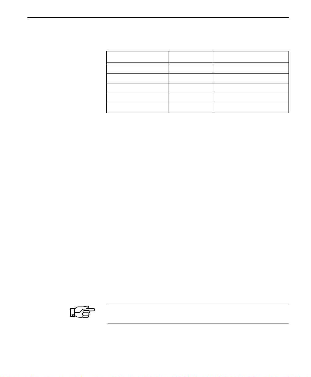
3 = CONFIG
Specified times for the SHORT and LONG delays at the different
operating speeds are:
Rate Short Delay Long Delay
64 1.1ms 16.1ms
56 1.1ms 16.1ms
19.2 1.5ms 16.5ms
4.8 1.5ms 16.5ms
2.4 1.5ms 16.5ms
Submenu 7 anti -stream
The ANTI-STREAM option is used to select the anti-stream timeout. The
anti-stream timeout is the maximum time the ConnecT 56K DSU
transmits data into the network from the DTE. This feature prevents one
DTE device on a multi-drop network from continuously tieing up the
transmit circuit back to the master DSU.
The anti-stream timer is reset to zero when RS transitions to the active
state and is updated every second while RS is active. When the antistream timeout expires, the ConnecT 56K DSU stops transmitting DTE
data into the network but continues to accept data from it. This condition
exists until the DTE deactivates the RS input.
Menu map
3=CONFIG/1=Local/2=DTE Opt./7Anti-Stream
Operation
Follow standard operating procedures. When 7=ANTI-STREAM is
flashing: Press the Enter button resulting in the displaying of the first of
the submenu items.
1=Timer Off
2=Time 10 Sec.
Note:
If one of the options chosen involves request to send (RS), then
the delay from RS to CS is selected.
ConnecT 56K DS User Manual
3-37
Page 68
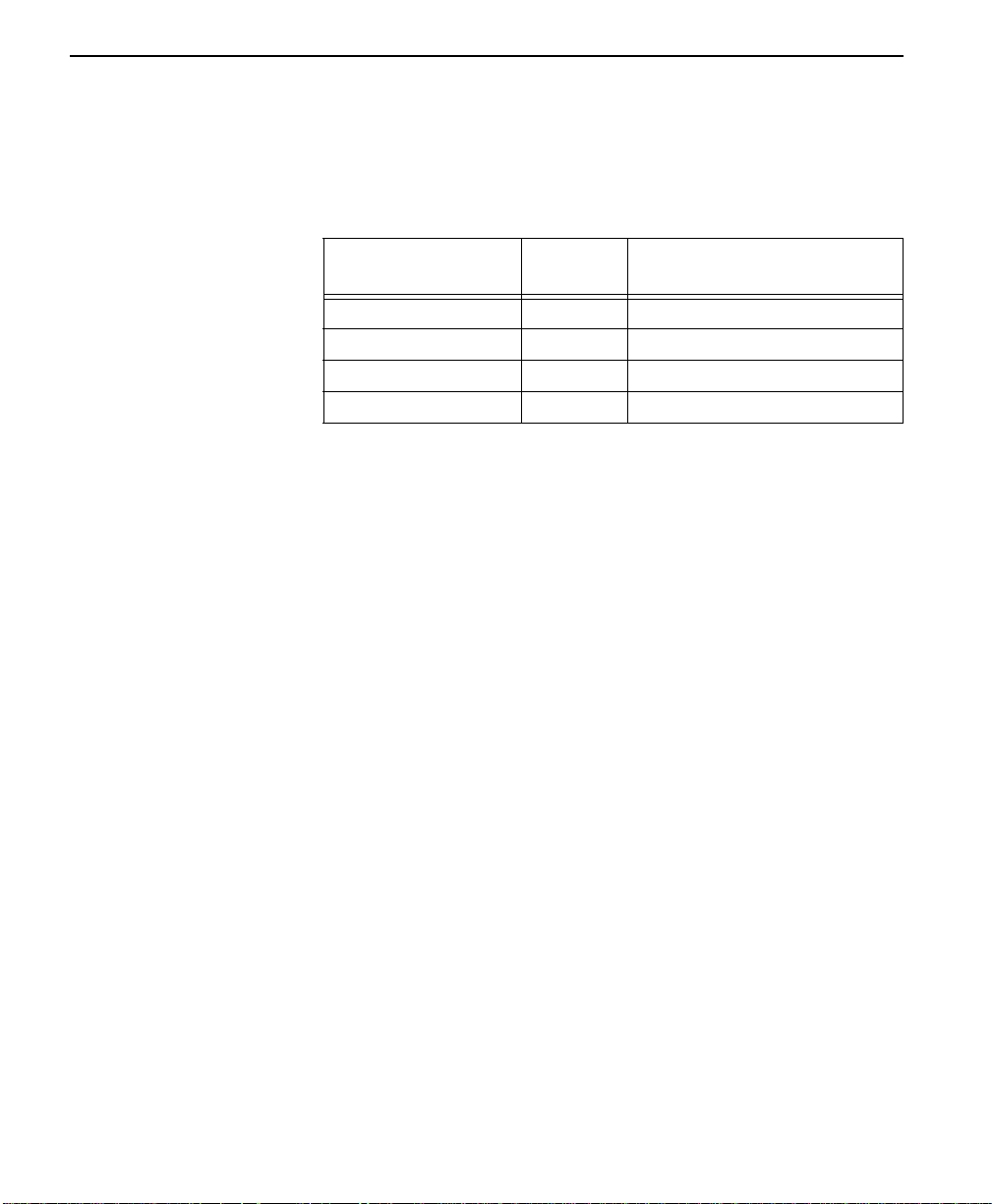
Operation
Continue with standard operating procedures to select menu options. At
the end of the options the system wilL briefly display “Command
Accepted” and return to the DTE OPTIONS menu with the Anti-Stream
selection active.
Table 3-24 Anti-Stream Commands
Front Pa nel
1=TIMER OFF %T0 Anti-stream timer disabled
2=TIME 10 SEC. %T1 Timeout equals 10 seconds
3=TIME 30 SEC. %T2 Timeout equals 30 seconds
4=TIME 60 SEC. %T3 Timeout equals 60 seconds
AT
Command
Description
Submenu 8 CD options
The CD OPTIONS menu is used to select one of three different control
modes for the receive line signal detector (CD) lead.
Menu map
3=CONFIG/1=Local/2=DTE Opt./8=CD Options
Operation
Follow standard operating procedures. When 6=CS OPTIONS is
flashing: Press the Enter button resulting in the displaying of the first of
the submenu items.
1=Forced on
2=Normal
3-38
Continue with standard operating procedures to select menu options. At
the end of the options the system wilL briefly display “Command
Accepted” and return to the DTE OPTIONS MENU.
ConnecT 56K DSU User Manual
Page 69
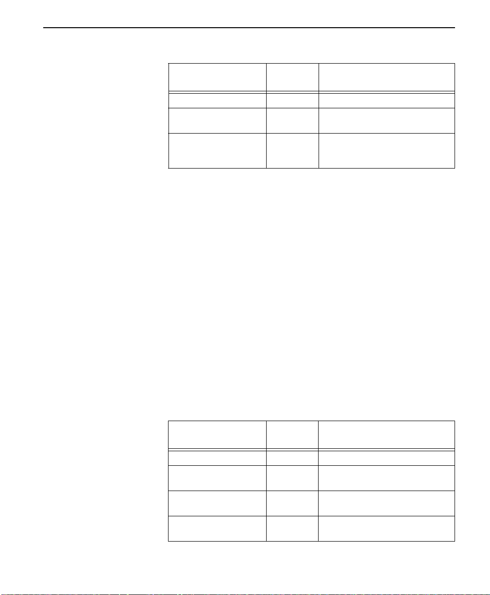
Table 3-25 CD Options Commands
3 = CONFIG
Front Pa nel
1=FORCED ON &C0 CD always ON
2=NORMAL &C1 ON only when data present on
3=OFF WITH LOCD &C2 ON except 5 seconds after
AT
Command
Description
loop
disconnect in switched 56
applications
Submenu 9 TR Options
The TR OPTIONS menu is used to select the ConnecT 56K DSU
response to the data terminal ready (TR) lead.
Menu map
3=CONFIG/1=Local/2=DTE Opt./9=TR Options
Operation
Follow standard operating procedures. When 9=TR OPTIONS is
flashing: Press the Enter button resulting in the displaying of the first of
the submenu items.
1=IGNORED
2=IDLE WHEN OFF
Continue with standard operating procedures to select menu options. At
the end of the options the system will briefly display “Command
Accepted” and return to the active menu.
Table 3-26 TR Options Commands
Front Panel
1=IGNORE &D0 TR input ignored
2=IDLE WHEN OFF &D1 ON only when data present on
3=OFF>ON DIAL #1 &D3 Dial stored #1:
4=OFF>ON DIAL #2 &D4 Dial stored #2:
AT
Command
Description
loop
TR goes OFF to ON
TR goes OFF to ON
ConnecT 56K DS User Manual
3-39
Page 70
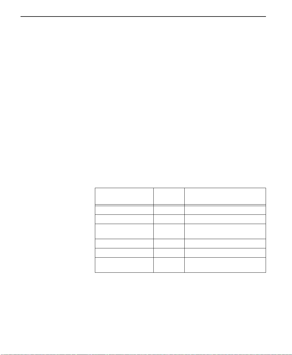
Operation
Submenu A SR options
The SR Options menu is used to select the operating mode for the data set
ready (SR) lead.
Menu map
3=CONFIG/1=Local/2=DTE Opt./A=SR Options
Operation
To display the SR Options submenu of 1=Local submenu of 3=CONFIG.
Use the scroll buttons to display the 9=Tr Options and A=SR Options.
Press the * (Shift) key to activate the alpha selections Use the letter A to
activate the SR Options submenu press the Enter key to enter the SR
Options submenu resulting in the displaying of the first of the SR Options
submenu items .
1=Forced On
2=Off OOS ONLY
Continue with standard operating procedures to select menu options. At
the end of the options the system will briefly display “Command
Accepted” and return to the active menu.
3-40
Table 3-27 SR Options Commands
Front Panel
1=FORCED ON &S0 SR always ON
2=OFF OOS ONLY &S1 OFF when network out of service
3=OFF LOCD ONLY &S2 OFF 5 seconds after disconnect
4=OFF TEST ONLY &S3 OFF for test only
5=OFF TEST + OOS &S4 OFF for test or OOS
6=OFF TEST + LOCD &S5 OFF 5 seconds are di sconnect for
Submenu B seconda y rate
The Secondary Rate option is used to select the operating speed for the
secondary channel if the secondary channel option was selected during
setup of the NETWORK OPT.
ConnecT 56K DSU User Manual
AT
Command
Description
in switched 56 applicatio ns.
test
Page 71

3 = CONFIG
Menu map
3=CONFIG/1=Local/2=DTE Opt./B=Secondary Rate
Operation
To display the Secondary Rate submenu of 1=LOCAL submenu of
3=CONFIG. Use the scroll buttons to display the B=Secondary Rate
press the * (Shift) key to activate the alpha selections Use the letter B to
activate the Secondary Rate submenu press the Enter key to enter the
Secondary Rate submenu resulting in the displaying of the first of the
Secondary Rate submenu it ems .
1=Off 2=75
3=150 4=300
Continue with standard operating procedures to select menu options. At
the end of the options the system will briefly display “Command
Accepted” and return to the active menu.
Table 3-28 Secondary Rate Commands
3=Test options
Front Pa nel
1=OFF _Y0 No secondary channel selected
2=75 _Y1 Secondary channel rate: 75Bps
3=150 _Y2 Secondary channel rate: 150 Bps
4=300 _Y3 Secondary channel rate: 300 Bps
5=600 _Y4 Secondary channel rate: 600 Bps
6=1.2K _Y5 Secondary channel rate: 1200
7=2.4K _Y6 Secondary channel rate: 2400
AT
Command
Description
Bps
Bps
The T est Options menu is used to enable or disable diffe rent te st modes as
well as specify the maximum test time allowed.
ConnecT 56K DS User Manual
3-41
Page 72
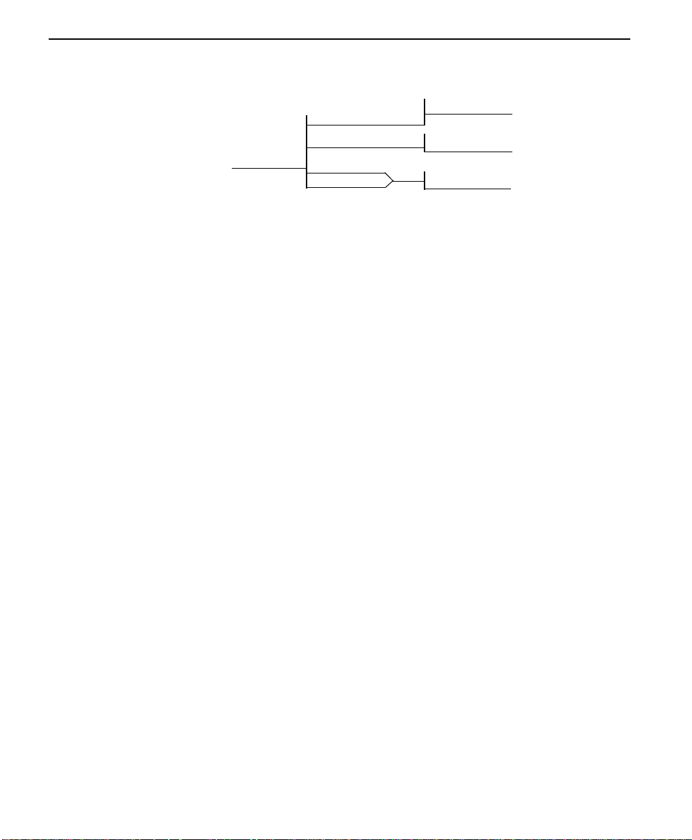
Operation
ENTER TIMOUT
(0=OFF) : 00SEC
1=RDL IGNORED
2=RDL ACCEPTED
1=DISABLED
2=ENABLED
3=TEST OPTIONS
1=TEST TIME OUT
2=RDL EN/DIS
3=EIA LLB EN/DIS
4=EIA RLB EN/DIS
Menu map
3=CONFIG/1=Local/3=Test Options
Operation
Follow standard operating procedures. When 3=TEST OPTIONS is
flashing: Press the Enter button resulting in the displaying of the first of
the Test Option submenu items. Continue with standard operating
procedures to select menu options. At the end of the options the system
will briefly display “Command Accepted” and return to the active menu.
3-42
Submenu 1 test timeout
The Test Timeout option is used to specify the length of time a ConnecT
56K DSU remains in a test mode before an automatic return to the data
mode. The LCD displays:
ENTER TIMEOUT
(0=OFF): 00SEC
Enter the time out in two digit decimal value.
Submenu 2 RDL select
The RDL Select option is used to specify whether or not the ConnecT
56K DSU responds to a remote digital loopback (RDL) request from the
far end of the circuit.
ConnecT 56K DSU User Manual
Page 73
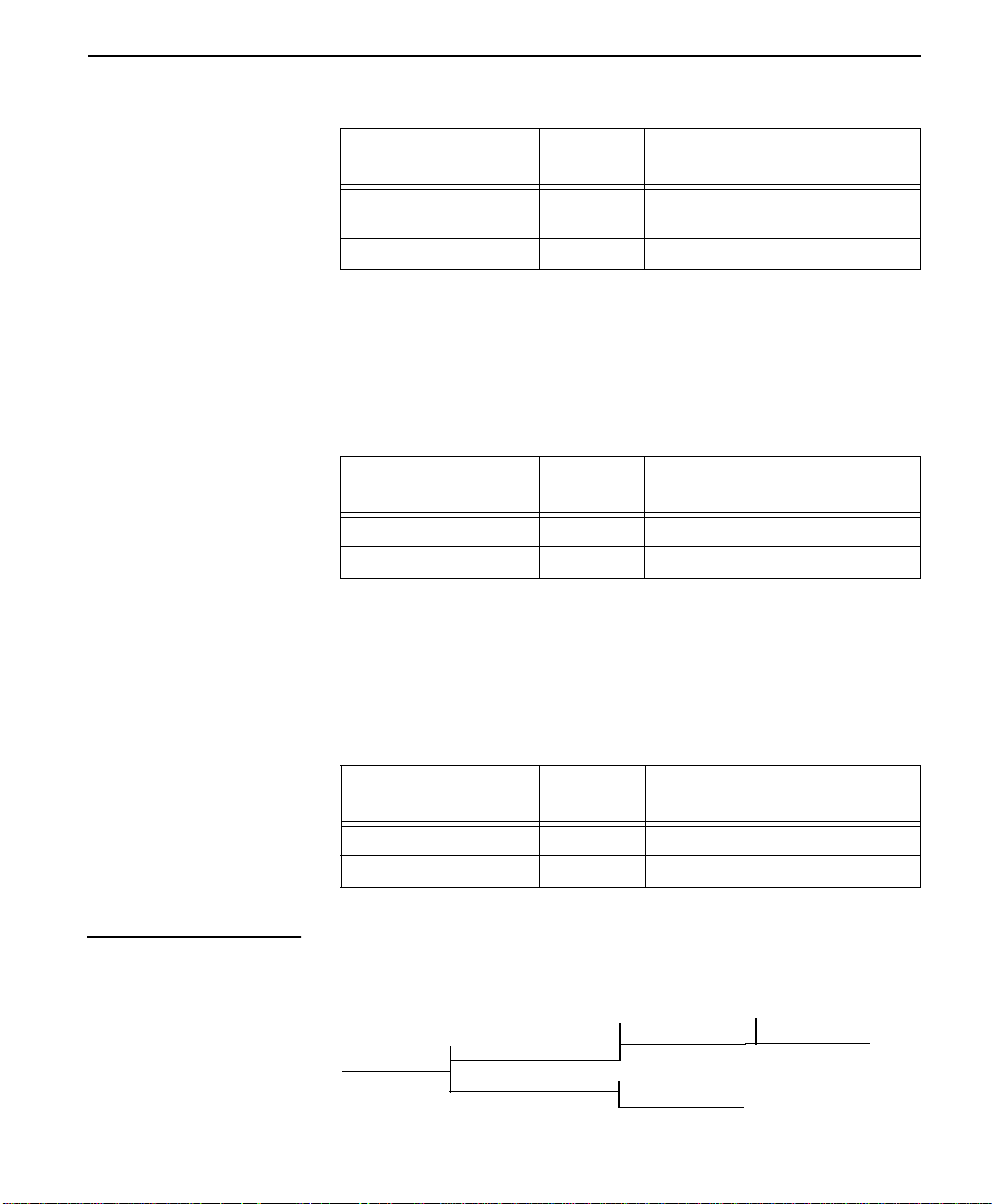
Table 3-29 RDL Select Commands
3 = CONFIG
Front Panel
AT
Command
Description
1=RDL IGNORED &T5 RDL request from remote DSU
ignored
2=RDL ACCEPTED &T4 RDL request accepted
Submenu 3 EIA LLB select
The EIA LLB Select option is used to specify whether or not the
ConnecT 56K DSU responds to the local loopback (LLB) input from the
DTE.
Table 3-30 EIA LLB Select Commands
Front Panel
AT
Command
Description
1=DISABLED _R0 EIA LLB disabled
2=ENABLED _R1 EIA LLB enabled
Submenu 4 EIA RLB select
The EIA RLB Select option is used to specify whether or not the
ConnecT 56K DSU responds to the remote loopback (RLB) input from
the DTE.
4 = Dial options
Table 3-31 EIA RLB Select Commands
Front Pa nel
AT
Command
Description
1=DISABLED _R0 EIA RLB disabled
2=ENABLED _R1 EIA RLB enabled
The Dial Option menu is used to store up to ten phone numbers and
define Answer operation of the ConnecT 56K DSU when it is configured
for Switched 56 operation.
4=DIAL OPTIONS
1=PHONE NUMBER
2=AUTO ANSWER
STORED NUMBER TO
EDIT: (1-10) 1
1=DISABLED
2=ENABLED
ConnecT 56K DS User Manual
NNNNNNN
3-43
Page 74

Operation
Menu map
3=CONFIG/1=Local/4=Dial Options
Operation
Follow standard operating procedures. When 4=Dial Options is flashing:
Press the Enter button resulting in the displaying of the first of the Dial
Option submenu items.
Continue with standard operating procedures to select menu options. At
the end of the options the system will briefly display “Command
Accepted” and return to the active menu.
Submenu 1 phone number
The ConnecT 56K DSU has storage for ten (10) numbers of 36 digits
each. If a phone number is to be edited, the entire number must be reentered. This process over writes the previously stored number.
STORE NUMBER TO
EDIT (1-10): X
3-44
Operation
Use the number key to type the number to be edited press Enter resulting
in the number being displayed for editing. Typing numbers will begin a
new entry from left to right.
Submenu 2 auto answer
The Auto Answer option is used to specify whether incoming calls are to
be automatically answered by the ConnecT 56K DSU or manually by the
user.
Table 3-32 Auto Answer Commands
Front Pa nel
1=DISABLED _J0 Auto Answer disabled
2=ENABLED _J1 Auto Answer enabled
ConnecT 56K DSU User Manual
AT
Command
Description
Page 75

5 = Manual command
3 = CONFIG
The Manual Command option is a short cut method for entering
configuration and control commands for the ConnecT 56K DSU.
Operation
The first display prompts the user to enter the command number.
COMMAND:00
Use the number keys to enter the hexadecimal command number press
the Enter key resulting in the command number being entered. The
display shows both the command number and the present value or setting
for the command. The command value can be edited or re-issued with the
exiting value.
COMMAND: XX
VALUE: 00
Use the number ke ys to enter t he he x adecimal v alue press the Enter key to
complete resulting in the system briefly displaying “Command
Accepted” and returning to the active menu.
Use the Manual Command option to access the configuration profiles
listed in Table A-3, “Configuration Prof iles,” on page A-6. The command
values are:
T able 3-33 Manual Command Values for Profiles
Command Profile
Command 8A
Value 00
Command 8A
Value 01
Command 8A
Value 02
Command 8A
Value 03
ConnecT 56K DS User Manual
1
2
3
4
3-45
Page 76

Operation
3-46
ConnecT 56K DSU User Manual
Page 77

Appendix
A Reference
This appendix provides information about warranty and customer service,
what information is required by the telephone company, and AT
commands. It also provides a table of configuration profiles you can load
manually and many of the reference figures that are referred to in this
manual.
W arra n ty and custo mer service
This unit contains no user serviceable parts. If it does not meet its
published specifications or fails while in service, Verilink will replace or
repair this product withi n five (5) years from the date of sh ipment. For
detailed warranty, repair and return information refer to the Verilink
Equipment Warranty and Repair and Return Policy Procedure.
Return Material Authorization (RMA) is required prior to returning
equipment to Verilink. For Service, RMA requests, or more information,
contact:
Veri link Custo mer Service:
145 Baytech Drive
San Jose CA 95134
(408) 945-1199
Repair and Return Address:
145 Baytech Drive
San Jose CA 95134
ConnecT 56K DSU User Manual A-1
Page 78

Telephone company information
The following information may be required when applying to your local
telephone company for leased line facilities.
Table A-1 Telephone company information
Service T ype
2.4 kbps Digital Interface 04DU5-24 6.0F RJ48S
4.8kbps Digital Interface 04DU5-48 6.0F RJ48S
9.6 kbps Digital Interface 04DU5-96 6.0F RJ48S
56 kbps Digital Interface 04DU5-56 6.0F RJ48S
Digital
Facility
Interface
Code
Service
Order
Code
Network
Jack
A-2 ConnecT 56K DSU User Manu al
Page 79

AT commands
AT commands
The following table lists the AT commands supported by the ConnecT
56K DSU.
T able A-2 AT Commands
AT Commands
Command Title Default
A/ Re-execute command none
ATA Answer none
ATDn Dial number none
ATE Echo command 1
ATH Hang up call none
ATO Go online none
ATQn Result code display 0
ATSn? Read S register none
ATSN=x Write to register none
ATVn Result code form 1
ATZ Reset none
AT&Cn DCD option 0
AT&Dn DTR option 0
AT&Fn Restore factory options none
AT&Kn Flow control none
AT&Ln Network type 0
AT&Qn D TE data format 0
AT&Rn CS options 0
AT&Sn SR options 0
AT&Tn Test commands 0
ConnecT 56K DSU User Manual
A-3
Page 80

AT Commands
Command Title Default
AT&V View current configuration none
AT&Wn Store user profile 0
AT&Xn Transmit clock 0
AT&Yn Power up user profile 0
AT&Zn=x Store phone number none
AT\Tn Inactivity timer none
AT%Bn Loop rate selected 0
AT%Kn DTE rate selected none
AT%P Password control 0
AT%P=x Password entry 0
AT%P>x Password verify 0
AT%Rx Initiate remote configuration 0
AT%Tn Anti-stream option 0
A-4 ConnecT 56K DSU User Manu al
AT_An LLB control 0
AT_Cn SR control during test 0
AT_Dn RTS-CTS dela 0
AT_Fn Scrambler control 0
AT_Jn Auto answer enable/disable 0
AT_N=xx Set network address none
AT_Pn Front panel enable/disable 0
AT_RR LB enable/disable 0
AT_S=xx Set serial number none
Page 81

AT commands
AT Commands
Command Title Default
AT_Tn Select test pattern 0
AT_Xn Clock source select 0
AT_Yn Secondary channel rate select 0
ConnecT 56K DSU User Manual
A-5
Page 82
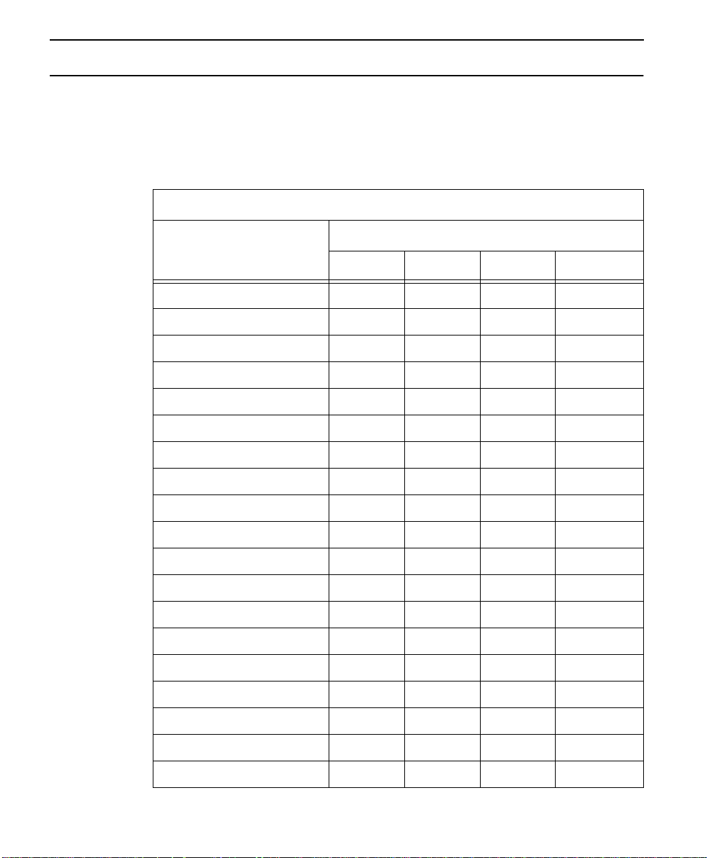
Configuration profiles
The following table lists the configuration p rofiles you can load using the
Manual Command option.
Table A-3 Configuration Profiles
Escape characte r +(2BH) + + +
CR character CR(ODH) CR CR CR
LF character LF(OAH) LF LF LF
BS character BS(08) BS BS BS
Escape guard time 50 50 50 50
Command echo DIS DIS DIS DIS
Result code EN EN EN EN
Long or short code LONG LONG LONG LONG
Defaults for ConnecT 56K DSU
Profile Numbers
123 4
Test pattern type 2047 2047 2047 2047
EIA controlled ALB DIS DIS DIS DIS
EIA controlled RLB DIS DIS DIS DIS
DTE TYPE V.35 RS232 V.35 V.35
Front panel enable/disable EN EN EN EN
Test timeout OFF OFF OFF OFF
DTE Command Set DIS DIS DIS DIS
CS option RS RS RS RS
SR test option OFF OFF OFF OFF
TR option IGNORE IGNORE IGNORE IGNORE
DTR recog. delay(X100ms) 3 3 3 3
A-6 ConnecT 56K DSU User Manu al
Page 83
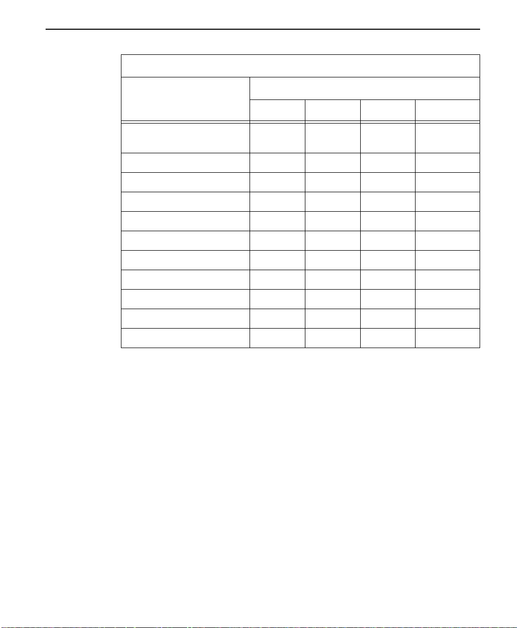
Defaults for ConnecT 56K DSU
Profile Numbers
123 4
Configuration profiles
DTR command timeout
30 30 30 30
(X100)
CD option NRML NRML NRML NRML
SR option NRML NRML NRML NRML
RDL enable disable EN EN EN EN
DTE rate (56K loop) 56K 57.6K 56K 56K
RS-CTS dela SHRT SHRT SHRT SHRT
DTE data format SYNC ASYNC SYNC SYNC
TC timing source INT INT INT INT
TX loop timin g LOOP LOOP LOOP LOOP
Anti-stream time OFF OFF OFF OFF
Inactivity timer OFF OFF OFF OFF
ConnecT 56K DSU User Manual
A-7
Page 84
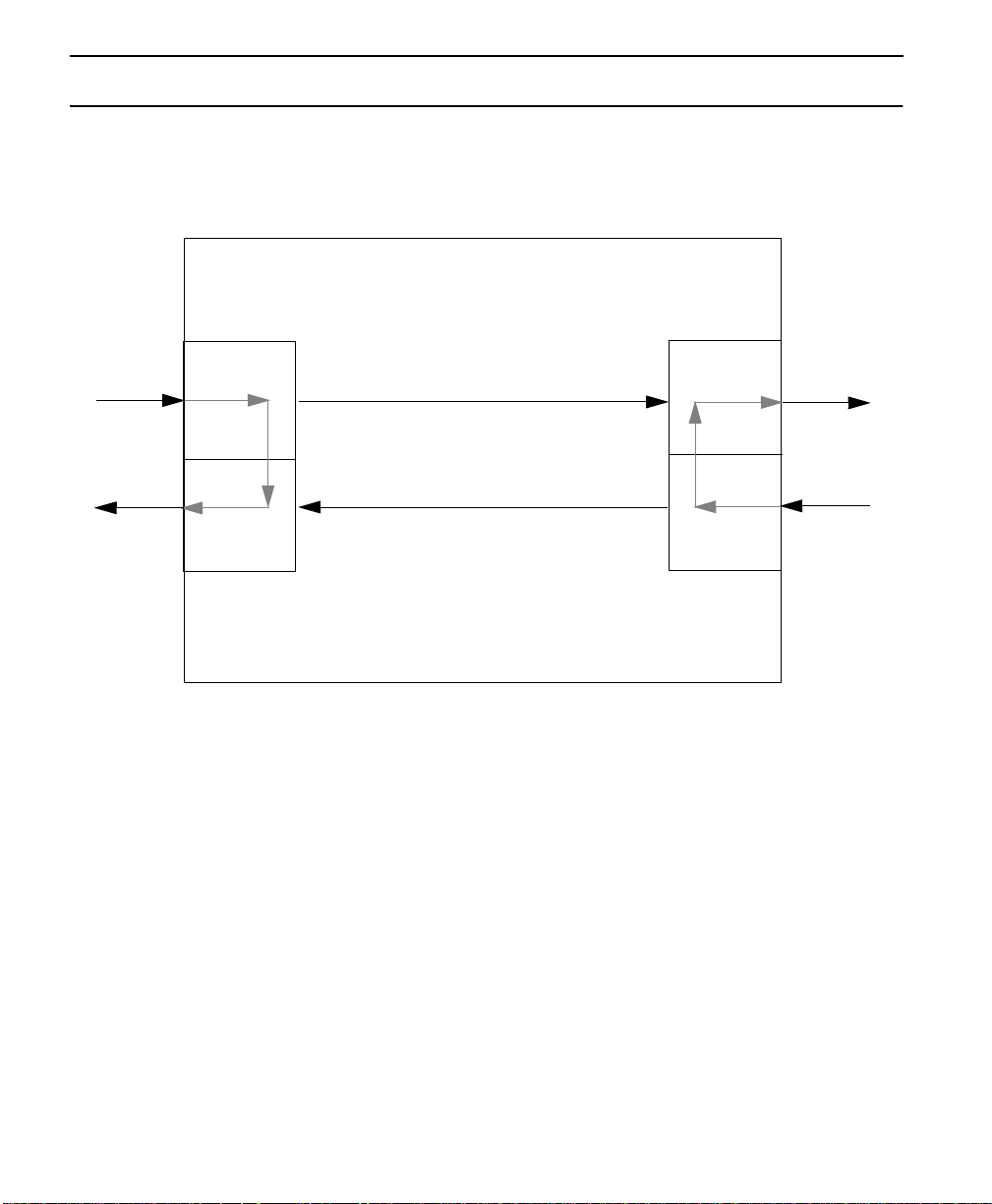
Figures
This section lists the figures referred to throughout the manual.
Figure A-1 DTE and Loop Test Diagram
DTE TD
DTE RD
DTE Transmit
Interface
DTE Receive
Interface
DTE and Loop
Loop Transmit
Interface
Loop Receive
Interface
Loop TX
Loop RX
A-8 ConnecT 56K DSU User Manu al
Page 85
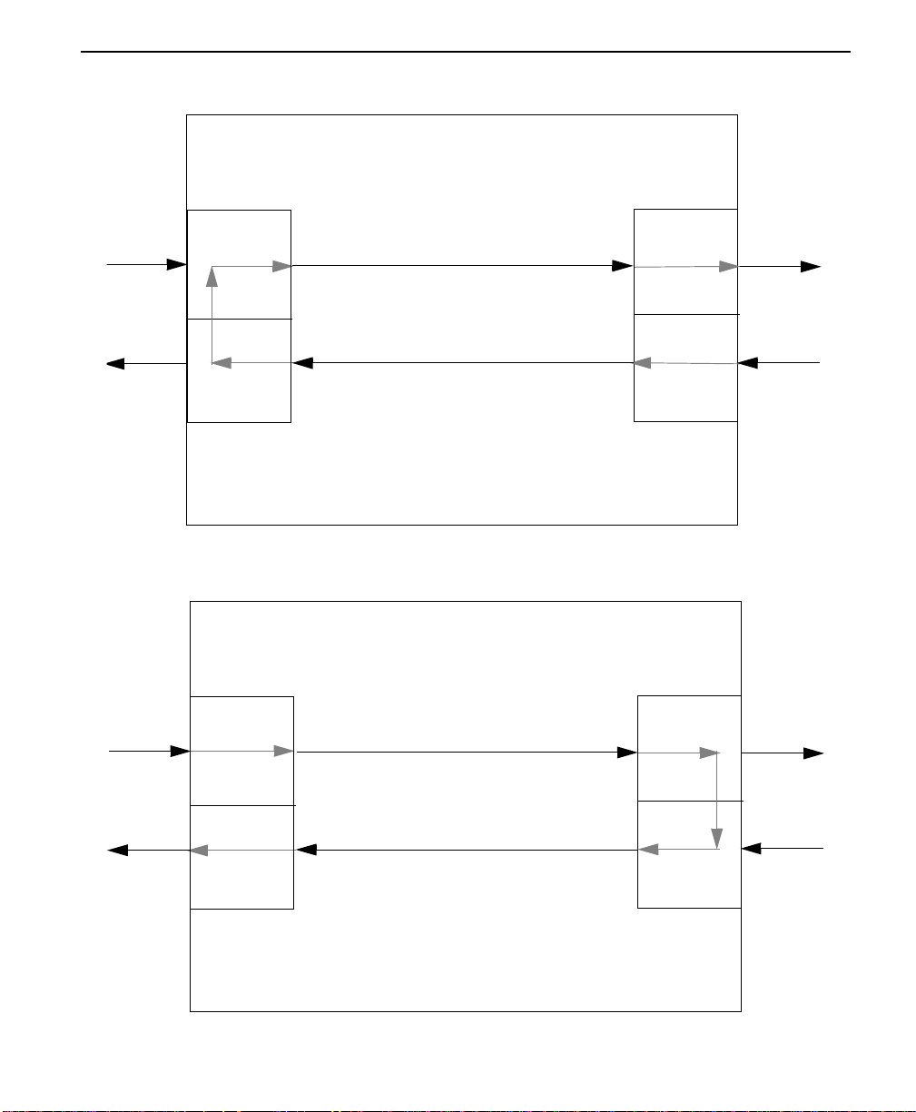
Figure A-2 Loop Only Test Diagram
Figures
DTE Transmit
DTE TD
DTE RD
Interface
DTE Receive
Interface
Figure A-3 DTE Only Test Diagram
DTE Transmit
DTE TD
Interface
Loop Only
Loop Transmit
Interface
Loop Receive
Interface
Loop Transmit
Interface
Loop TX
Loop RX
Loop TX
DTE RD
DTE Receive
Interface
DTE Only
Loop Receive
Interface
ConnecT 56K DSU User Manual
Loop RX
A-9
Page 86
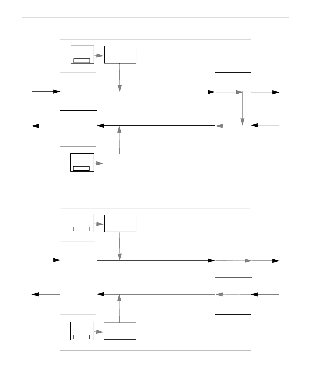
Figure A-4 DTE With Test Pattern Diagram
DTE TD
DTE RD
Error
Inject
#
DTE Transmit
Interface
DTE Receive
Interface
Error
Clear
1
Test Pattern
Generator
Test Pattern
Detector
Figure A-5 Test Pattern Only Diagram
Error
Inject
#
Test Pattern
Generator
DTE with Test Patter
Loop Transmit
Interface
Loop Receive
Interface
Loop TX
Loop RX
DTE Transmit
DTE TD
DTE RD
Interface
DTE Receive
Interface
Error
Clear
1
A-10 ConnecT 56K DSU User Manual
Test Pattern
Detector
Test Pattern Only
Loop Transmit
Interface
Loop Receive
Interface
Loop TX
Loop RX
Page 87
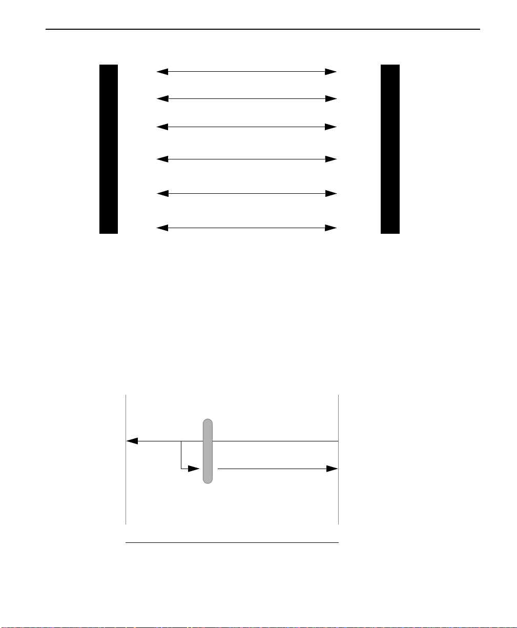
Figure A-6 DSU to Modem Interconnect Diagram
RC
ETC
M
RD
O
D
E
TD
M
For multi-drop requirement:
DCD
ETC
RC
TD
RD
RTS
Figures
C
o
n
n
e
c
T
5
6
K
D
S
U
RTS
Figure A-7 EIA 232 Connector for 56 KB/s and 64 KB/s Application
DTE
At DTE Interface RS 232 connector, tie transmit
clock lead (SCT) to external transmit clock (ETC) as
shown. This may resolve data error problems caused
by signal delays at high rates.
DTE
(No connection)
Pin 15
Pin 24
RS 232 Connector
SCT
ETC
ConnecT 56K DSU
DCD
ConnecT 56K DSU
Options for EXT TX CLK
ConnecT 56K DSU User Manual
A-11
Page 88

A-12 ConnecT 56K DSU User Manual
 Loading...