

Page 1

Verilink Access System 2000
The Basics
October 1999
P/N 880-502981-001-H
Page 2

Copyright Notice
Copyright 1999 Verilink Corporation. All rights reserved.
This document does not create any express or implied warranty about Verilink or
about its products or services. Verilink’s sole warranty is contained in its product
warranty. The end-user documentation is shipped with Verilink’s products and
constitutes the sole specifications referred to in the product warranty. Verilink has
made reasonable efforts to verify that the information contain ed h erein is accurate,
but Verilink assumes no responsibility for its use or for any infringement of patents
or other rights of third parties that may result. The customer is solely responsible
for verifying the suitability of Verilink’s pro ducts for its use. Specifications are
subject to change without notice.
Trademarks
FCC Requirements
Lithium Battery
English
Verilink is a registered trademark of Verilink Corporation. Access System 2000,
WANscope, VeriStats, and FrameStart are trademarks of Verilink Corporation.
Any named prod ucts herein are trademarks of their respective companies.
This equipment has been tested and found to comply within the limits for a Class A
digital device pursuant to Par t 15 of the Federa l Communic ations C ommissio n (FCC)
rules. These limits are designed to pro vide protection against harmful interference
in a commercial environment.
This equipment generates, uses, an d can radiate radio frequency energy and, if not
installed and used in accordance with the user manual, can cause harmful
interference t o radio communications.
There is no guarantee that interference will not occur in a p articular installation. If
this equipment causes harmful interference to radio or television reception—which
can be determined by turning the equipment off and on—try to correct the
interference by one or more of the following measures:
Reorient or relocate the receiving antenna.
•
Increase the separation between the equipment and receiver.
•
Connect the equipment into an outlet on a circuit different from that to whi c h
•
the receiver is connected.
Consult the dealer or an experienced radio/TV technician for help.
•
The lithium battery referred to in the following notices is contained inside the clock
chip.
DANGER!
The battery can explode if incorrectly replaced! Replace only with the same or
equivalent type recommended by the manufacturer. Dispose of used batteries
according to the manufacturer’s instructions.
DANGER!
To avoid electrical shock in case of failure, the power supply must be installed
by a professional installer. The terminal labeled with the ground symbol ( )
on the power supply must be connected to a permanent earth ground.
CAUTION!
Interconnecting circuits must comply with the requirements of
EN60950:1992/A2:1933 Section 6.2 for telecommunications network voltages
(TNV) circuits.
Français
Une explosion peut se produire si la batterie est remplacée d’ une façon incorrecte! Remplacez-la seulement avec le même modêle de batterie ou un modèle
équivalent selon les recommendations de manufacture. Disposez de les batteries usées selon les instructions de manufacture.
ATTENTION!
ATTENTION!
Pour éviter choc électrique en cas de insuccès, la provision de pouvoir doit êtré
installé par un installeur professionnel. Le terminal de la provision de pouvoir,
marqué du symbol de terre, ( ) doit connecté à un circuit de terre permanent.
ii Verilink Access Sy stem 2000: The Basics
Page 3

ATTENTION!
Les circuits doivent êtré interconnectés de manière à ce que l’ équipement
continue a êtré en agrément avec “EN60950:1992/A2:1933, Section 6.2, pour les
circuits de voltage de liaisons d’ échanges (réseau) par les télécommunications
(TNV),” après les connections de circuits.
Españole
Deutsch
PELIGRO!
La bateria puede exp lotar si s e reempla za incorr ectamente. Reemp lace la bateri a
con el mismo tipo de bateria ó una equivalente recomendada por el manufacturero. Disponga de las baterias de acuerdo con las instrucciones del manufacturero.
PELIGRO!
Para evitar contacto con circuitos que electrocutan, la fuente de alimentación
debe ser instalada por un técnico profesional. La terminal de la fuente de al imentación marcada con el símbolo de tierra ( ) debe ser conectada a un circuito de vuelta por tierra permanente.
CIRCUITOS A INTERCONECTARSE
Circuitos que se int erc on ecta n a la re d de telecomunicaciones deben h ace r se de
tal manera que cumplan con los requisitos estipulados en las especificaciones
“EN60950:1992/A2:1933, Sección 6.2, para los voltages de circuitos
interconnectados a la Red de Telecomunicaciones (TNV),” despues de terminar
las connecciones entre los circuitos.
VORSICHT!
Explosionsgefahr bei unsachgemäßem Ersetzen der Batterie! Batterie gleichen
Typs und gleicher Qua lität ben utzen, wie v om Hersteller empfohlen. Entsor gung
der Batterie nach Anweisung des Herstellers!
VORSICHT, GEFAHR!
Um keinen Schlag zu erhalten beim Versagen der electrischen Anlage, muss der
Stromanschluss von einem Elektriker vorgenommen werden. Der elektrische
Pol, versehen mit dem Erdsymbol ( ) muss am Stromanschluss permanent
geerdet sein.
VORSICHT!
Schaltungen, die in den Geräten zusammengeschaltet sind, müssen weiterhin
den Vorschriften EN60950:1992/A2:1933, Absatz 6.2 für Telecommun ications
Netz Spannung (TNV) Schaltkreize entsprechen.
Canadian
Requirements
Safety Precautions
This digital apparatus does not exceed the Class A limits for radio noise emissions
from digital apparatus set out in the Radio Interference Regulations of the Canadian
Department of Communications.
Le présent appareil numérique n’émet pas de bruits radioélectriques dépassant les
limites applicables aux app a reils numériques (de la class A) prescrites dans le
Règlement sur le brouillage radioélectrique édicté par le ministère des
Communications du Canada.
This equipment is intended to be insta ll ed o nly in a Restricted Access Location that
meets the following criteria:
Access can only be gained by service personnel or users who have been
•
instructed about the reasons for the restrictions applied to the location and
about any precautions that must be taken.
Access can only be gai ned th rough th e use of a lock a nd ke y or ot her mea ns of
•
security, and is controlled by the autho r ity responsible for the location.
When handling this equipment, follow these basic safety precautions to reduce the
risk of electric shock and injury:
Verilink Access Sy stem 2000: The Basics iii
Page 4

Follow all wa rnings and inst ructions marked on the product and in the
•
manual.
Unplug the hardware from the w all outlet before cleaning. Do not use liquid
•
cleaners or aerosol cleaners. Use a cloth slightly dampened with water.
Do not place this product on an u nstable cart, stand, or table. It may fall,
•
causing serious damage to the product.
Slots and openings in the shelves are prov ide d for ve nti latio n to prote c t them
•
from overheating. These openings must not be blocked or covered. Never
place this product near a radiator or heat register.
This product should be op erated onl y from the t ype of power sou rce indicate d
•
on the marking label and manual. If you are unsure of the type of power
supply you are using, consult your dealer or local power company.
Do not allow anything to rest on the power cord. Do not locate this product
•
where the cord will interfere with the free movement of people.
Do not overload wall outlets and extension cords, as this can result in fire or
•
electric shock.
Never push objects of any kind into the sh elves. They may touch dangerous
•
voltage points or short out parts that could result in fire or electric shock.
Never spill liquid of any kind on this equipment.
Unplug the equipment from the wall outlet and refer servicing to qualified
•
service personnel under the following co nditions:
a. When the power supply cord or plug is damaged or frayed.
b. If liquid has been spilled into the product.
c. If the product has been exposed to rain or water.
d. If the product has been dropped or if the cabinet has been damaged.
Product Warranty
Customer Service
Publications Staff
Verilink’s product warranty covers re pair or replacement of all equipment under
normal use for a five-year period from date of shipment. Our in-house Repair Center
services returns within ten working days.
Verilink offers the following services:
System Engineers at regional sales offices for network design and planning
•
assistance (800.837.4546)
Technical Assistance Center for free 24x7 telephone support during
•
installation, maintenance, and troubleshooting (800.837.4546 x333,
support@verilink.com)
Return Materials Authorization (RMA) (800.837.4546 x332)
•
Maintenance contracts and leasing plans (800.837.4546. x206)
•
Technical Training on network concepts and Verilink products (800.837.4546
•
x346, training@verilink.com)
Web site (www.verilink.com)
•
FAX-On-Demand (800.957.5465)
•
This manual was written and illustrated by David Fradelis and Barbara Termaat.
Contributing writers include: Steve Rider, Marie Metivier, and Theresa Lau.
iv Verilink Access Sy stem 2000: The Basics
Page 5

Table of Contents
About this Manual
Access System 2000 Overview
AS2000 Concept.................................................................................................. 1-1
AS2000 System ................................................................................................... 1-2
Shelf Units.................................................................................................... 1-2
AS2000 Design.................................................................................................... 1-3
Advanced Communications Engine (ACE) .................................................... 1-3
AS2000 Management Options............................................................................. 1-4
Craft (ASCII) Interface................................................................................... 1-4
Node Manager............................................................................................... 1-5
SNMP............................................................................................................. 1-5
Management Support Cross-Reference ........................................................ 1-5
Access Manager 2000................................................................................... 1-6
Thumbwheel Switches.................................................................................. 1-6
Performance Monitoring..................................................................................... 1-6
System Information
Shelf Units .......................................................................................................... 2-1
Multi-line Shelf..................................................................................... 2-1
Quint-line Shelf .............................. ...................... ...................... ... ....... 2-1
Dual-line Shelf...................................................................................... 2-1
Data Bus Structure........................................................................................ 2-2
ACP Data Bus Structure ........................................................................ 2-3
ACP Controller Bus Structure ....................................................................... 2-4
Shelf and Node Masters....................................................................... 2-4
Types of Modules ............................................................................................... 2-5
Channel Service Unit Modules (CSU) .................................................... 2-5
Data Service Unit (DSU) Modules.......................................................... 2-6
Integrated DSU/CSU Modules............................................................... 2-7
Connector Interface Modules (CIMs) .................................................... 2-7
Controller Modules............................................................................... 2-7
AS2000 Modules ................................................................................................. 2-8
TABS-Based Application Modu le s.................................... ... ... ...................... . 2-8
TABS-Based Controller Module s .............................. ... ...................... ... . 2-8
ACP-Based Application Modules................................................................... 2-9
Node Controller Module....................................................................... 2-9
Timing .............................................................................................................. 2-10
Timing Source ............................................................................................ 2-10
CSU Timing......................................................................................... 2-10
DCE to DTE Timing......... ...................... ...................... ... ..................... 2 -11
Crossover Connection................. ...................... ... ...................... ........ 2-12
Tail Circuit Timing ............................................................................. 2-13
.......................................................................................................ix
................................................................................ 1-1
................................................................................................. 2-1
Verilink Access System 2000: The Basics v
Page 6

TABS-Based Timing Option s...................... ... ... ...................... ..................... 2- 13
ACP-Based Timing Options........................................................................ 2-13
Shelf vs. Card Timing......................................................................... 2-13
Timing Source .................................................................................... 2-14
Shelf Sync Master ............................................................................... 2-14
Site Planning
............................................................................................................. 3-1
Installation Planning........................................................................................... 3-1
Module Installation ...................................................................................... 3-1
TABS-Based Nodes................................................ ... ...................... ... .... 3-1
ACP-Based Nodes.................................................................................. 3-2
System Cabling Considerations.................................................................... 3-2
T1 Network Interface ........................................................................... 3-3
External Clock Source............... ... ...................... ... ...................... ... ....... 3-3
DTE Interface........................................................................................ 3-3
System Power Requirements ........................................................................ 3-3
Hardware Dimensions.................................................................................. 3-4
Heat Dissipation............................ ... ...................... ... ...................... ... .......... 3-5
Heat Baffles................................. ... ...................... ... ...................... ... .... 3-5
Fan Shelf............................................................................................... 3-5
Preparation Guidelines ....................................................................................... 3-7
FCC Part 68 (or Equivalent) C ompliance Statement ........... ... ... .................... 3-7
Configuration Worksh eet s ............ .... ..................... ...................... ... .................... 3-8
Pre-installation Que stionnaire.......... ... ... ...................... ... ...................... ....... 3-8
Node Summary Worksheets.......................................................................... 3-8
SNMP Node Planning Worksheet........................................................... 3-8
Shelf Planning Worksheets for TABs Modules.............................................. 3-9
Shelf Planning Worksheets for ACP Modules ............................................. 3-11
Hardware Installation
.............................................................................................. 4-1
Required Hardware and Tools ............................................................................ 4-1
Equipment Inspec tion.......... ...................... ...................... ... ...................... .......... 4-1
Wiring for DC Power Installation ......... ... ...................... ... ...................... ... .......... 4-2
Shelf Mounting.................................................................................................... 4-2
Mounting Brackets........................................................................................ 4-2
Installing and Groundi ng Pow er Supp lie s ............. ...................... ... .................... 4-4
Shelf Grounding ........................................................................................... 4-4
Quint-line Shelf Groundin g ............................... ... ... ...................... ... .... 4-5
AC Power Connections........................................................................................ 4-5
Multi-line and Quint-Line Shelves ................................................................ 4-5
Dual-line Shelf.............................................................................................. 4-5
DC Power Connections ..... ...................... ...................... ... ...................... ............. 4-6
Multi-line DC Power Connections................................................................. 4-6
Quint-line DC Power Connections...................................... ... ...................... . 4-7
Dual-line Shelf PWR 2940 and 2950 DC Power Connections........................ 4-7
Connect the Power Supply Alarm................................................................. 4-8
Fan Shelves................................................................................................... 4-9
AC Power Fan Shelf Connections.......................................................... 4-9
DC Power Fan Shelf Connection s ......... ... .... ..................... .................. 4-10
vi Verilink Access System 2000: The Basics
Page 7

Fan Alarm............................................................................................4-11
Installing the Rear Connector Module...............................................................4-12
Installing the Application Module ..............................................................4-12
TIU Installation ...........................................................................................4-13
TIU Connections .................................................................................4-13
System Power Application and Verification................................................ 4-14
Applying Multi-line Shel f DC Pow e r.............................. ...................... 4-14
Applying AC Power to 115 VAC Power Supplies (PAC 2910) ..............4-15
AS2000 Cabling ... .... ... ...................... ..................... ...................... ... ...................4-17
Setting the Shelf Address....................................................................4-18
Extending the TABs Node Controller Bus ...........................................4-19
Daisy-Chaining for the NCM ............ ... ...................... ...................... ............4-19
Data Bus Expansion.....................................................................................4-20
Connecting the Rear Connector Modules ...................................................4-20
ASCII Terminal Connection.........................................................................4-20
Monitoring and Troubleshooting
............................................................................5-1
Front Panel LED Indic ato r s.................. ...................... ...................... ... ...........5-1
Test Equipment ...................................................................................................5-1
System Failure.....................................................................................................5-2
Alarms.................................................................................................................5-2
Interpreting Alarms ......................................................................................5-3
Alarm Description.................................................................................5-3
Alarm Classification .............................................................................5-3
Problem Types ......................................................................................5-3
What To Do About Alarms ............................................................................5-4
Alarm List......................................................................................................5-4
Configuration Problems......................................................................................5-7
T1 Line Coding and Density Enforcement ....................................................5-7
AMI Coding and Pulse Stuffing .............................................................5-7
B8ZS Coding....... ...................... ... ...................... ...................... ... ...........5-7
Loopbacks and Test Patterns ..............................................................................5-8
Repeater Loopback (RLB) ..............................................................................5-9
Line Loopback (LLB) ......................................................................................5-9
Payload Loopback (PL B) ......... .... ..................... .... ..................... .....................5-9
Equipment Loopback (ELB)............................................................................5-9
Data Port Loopback (DPLB)..........................................................................5-10
Test Patterns...............................................................................................5-10
Performance Monitoring Registers.................................................................... 5-11
Performance Register Definitions...............................................................5-11
Performance Data Processing ..................................................................... 5-15
AT&T TR 54016 Performance Data Processing............. ... .... ...............5-15
ANSI TIM1.3 Performance Data Processing.........................................5-15
Verilink Performance Data Processing................................................5-16
Equipment Signal Performance Data Processing ................................5-16
Power Failure.............. ...................... ... ...................... ..................... ...................5-16
DC Power..................................................................................................... 5-16
AC Power.....................................................................................................5-17
System Fault Isolation ................................................................................5-19
Verilink Access System 2000: The Basics
vii
Page 8

Check System Power .......... ..................... .... ..................... .................. 5-19
Verify Self Test................................................................................... 5-19
Check System Configura tio n....................... ... ...................... ... ........... 5-19
NET Loopback.. ...................... ...................... ..................... .................. 5-19
Perform Application Equipment Loopback ........................................ 5-20
CSU Mode Troubleshooting................................................................ 5-20
Compliance Statements
........................................................................................... A-1
Line Aggregate Compliance ................................................................................ A-1
Data Interface Specifications ....................................................................... A-2
Mean Time Between Failure.......................................................................... A-2
British Approvals Board of Telecommunications (BABT) ................................... A-2
Cabling ......................................................................................................... A-3
Required Information for Instructions and Testing..................................... A-3
Tolerance to Wander .................................................................................... A-4
Certifications and Compliance ........................................................................... A-4
System Cables
............................................................................................................B-1
Acronyms.............................................................................................................B-1
Illustrated Parts List ............................................................................................B-2
T1/E1 Line Interface Cables...............................................................................B-22
Acronyms and Definitions
............................................................................ glossary-1
viii Verilink Access Sy stem 2000: The Basics
Page 9

Preface
About this Manual
This manual is the foundational documentation for Verilink’s
Access System 2000. It provides general information for the
modular equipment used within the Access System 2000.
Organized for first- time installation and set -u p o f Access 2000
equipment, this manual contains the following chapters:
Chapter 1: Access System 2000 Overview
Chapter 2: System Information
Chapter 3: Site Planning
Chapter 4: Hardware Install ation
Chapter 5: Fault Isolation
Appendix A: Compliancy Statements
Appendix B: System Cables
Glossary
Index
Verilink Access Sy stem 2000: The Basics ix
Page 10

About this Manual
x Verilink Access System 2000: The Basics
Page 11

Chapter
1
AS2000 Concept
Access System 2000 Overview
Access System 2000 (AS2000) is a uniform system that provides
multiple access interfaces to network services for voice, data, and
video applications. The AS2000 is a bandwidth manager of Level 1
digital services. The Advanced Communications Engine (ACE)
architecture brings the bandwidth management capabilities of the
AS2000 to Level 0 channels (DS0 and E0) and Level 3 channels
(DS3).
The AS2000 system is modular by design, providing different types
of data, network, and mana gement ports. The syst em’s applic ation
components can be managed individually or through a controller
card, locally or remotely. End-user applications include Local Area
Networks (LANs), video conferencing and imaging, digital voice,
and remote terminal-to-mainframe connections.
An AS2000 system consi sts o f one o r more nod es. An AS2000 node
is a combination of up to four shelf units, providing network
support for private networks, virtual private networks, FT1, T1,
FE1, E1, T3, and ISDN PRI. For network ma nagement, the Access
System 2000:
•
Generates and stores non-service-affecting T1/E1 circuit
performance data for circuit analysis and maintenance.
•
Generates alarms for fault conditions from incoming
network/equipment signals, and reports the alarms to th e
AS2000 applicatio n.
•
Stores operator-defined configuration settings required for
network and equipment interfaces.
The AS2000 Advanced Programmable Architec ture (APA) enables
new features and firmware upgrades through local or remote
downloads. The download process uses File Transfer Protocol
(FTP) or the Access Manager 2000 prog ram, depending on the
controller module used. Figure 1-1 illustrates the flexibility of the
AS2000 platform.
Verilink Access Sy stem 2000: The Basics 1-1
Page 12

Access System 2000 Overview
Figure 1-1 AS2000 System
User
300 bit/s to 19.2 Kbit/s
Low
Speed
Carrier
Frame Relay
ATM
User
HSSI
Router
56K
Router
Nx56K
Video
Host/FEP
Channel
Extension
PBX
NxT1/E1
T1
AS2000 System
V.35
RS-449
EIA 530
Router
Video
Channel
Extension
AS2000
NxT1/E1
PRI
T1/E1
ISDN
Private
T3/E3
PRI
AS2000
FE1/FT1
Network
Services
SNMP
Manager
The AS2000 system consists of application modules and mating
connector interface modules (CIMs). Application modules fit into
the front shelf slots and house the processors required for the
designated application . The fr ont panels contain status LEDs and
management ports.
X.21/RS-232
Router
Network and information ports reside on the rear connector
interface modules, which slide into a corresponding slot on the
back of the shelf. These ports are available with different types of
physical and electrical i nterfaces. The shelf unit contains a
controller bus and data bus for module recognition and data
transfer. Controller modu les interface the entire node t o sof tware
management applicatio ns.
Shelf Units
AS2000 shelf units house the network access modules, and can be
mounted in 19– or 23–inch equipment racks. The shelf units
contain the buses and power connections for the AS2000. There
are five types of shelf units available:
•
Multi-line Shelves (MLS 2000, MLS 2200, and MLS 2200-4i)
•
Quint-line Shelf 2500 (QLS 2500)
•
Dual-line Shelf 2100 ( DLS 2100)
1-2 Verilink Access System 2000: The Basics
Page 13

AS2000 Design
Access System 2000 Overview
The AS2000 system is designed to operate under the Telemetry
Asynchronous Bit Serial Protocol (TABS protocol) and the Advanced
Communication Protocol (ACP). TABS is an industry-wide
controller protocol. Verilink’s ACP is a faster and more powerful
protocol developed as a part of the Advanced Communication
Engine (ACE) architecture. AS2000 provides same-shelf integration
of TABS and AC P-based modules through the us e of the Node
Controller Module (NCM 2000).
Advanced Communications Engine (ACE)
Verilink’s Advanced Communications Engine (ACE) architecture
supports international carrier channel standards, including E1, T1,
DS3, and ISDN Primary Rate Interface (PRI). The ACE architecture
uses the Advanced Communication Protocol (ACP) to communicate
between modules. The ACE architecture adds a cross-conne ct
switch, enabling individual Level 0 channels to be directed to a port
within a module, or to the port of another module within the node.
The ACE architecture transforms a shelf of individual modules into
a bandwidth manager.
Verilink Access Sy stem 2000: The Basics 1-3
Page 14

Access System 2000 Overview
AS2000 Management Options
There are five methods of node management for AS2000. The five
management options are:
Craft (ASCII) Interface
•
Craft or L
•
Node Manager program (a GUI interface that can manage an
OCAL
port (ASCII) interface.
entire AS2000 network) .
•
SNMP interface, using Manager of Managers (MOM).
•
Access Manager 2000, a screen-based software product that
manages NCC controller modules. (Not Y2K ready).
•
Thumbwheel switches, a mechanical way to configure certain
TABS-based modules.
The Craft interface is accessed by connecting directly to the port
labelled C
RAFT
or L
OCAL
on the front panel of a node controller
module. This interface can configure any module in the local node.
A Craft cable connects the mod ule to a pe r s ona l com pu t er in
terminal mode, providing a direct connection to the firmware
within the module. A node containg an SCC or NCM control ler
module can be managed remotel y using a personal computer,
Telnet, and the IP address of the remote node controller. Figure 1-2
is an example of an ASCII screen.
NOTE:
The NCC 2020 and NCC 213 0 node control ler modu les do not
support remote man agement by Telnet.
Figure 1-2 Example Craft Interface Menu
-- VERILINK NCM CONTROLLER : FW Rev 4.33, Sep 10 1999 15:06:43 --
-- VERILINK NCM CONTROLLER : FW Rev 4.33, Sep 10 1999 15:06:43 --
-- VERILINK NCM CONTROLLER : FW Rev 4.33, Sep 10 1999 15:06:43 ---- VERILINK NCM CONTROLLER : FW Rev 4.33, Sep 10 1999 15:06:43 - Site Name: Tech Pubs Access Level: 2
Site Name: Tech Pubs Access Level: 2
Site Name: Tech Pubs Access Level: 2 Site Name: Tech Pubs Access Level: 2
Managing at NEAR end node [127.255.255.0] Node ID: 64352
Managing at NEAR end node [127.255.255.0] Node ID: 64352
Managing at NEAR end node [127.255.255.0] Node ID: 64352 Managing at NEAR end node [127.255.255.0] Node ID: 64352
<- SLOT ->
<- SLOT ->
<- SLOT -> <- SLOT ->
SHELF 1 2 3 4 5 6 7 8 9 10 11 12 13
SHELF 1 2 3 4 5 6 7 8 9 10 11 12 13
SHELF 1 2 3 4 5 6 7 8 9 10 11 12 13 SHELF 1 2 3 4 5 6 7 8 9 10 11 12 13
0 - - - - - - - - - - - - -
0 - - - - - - - - - - - - -
0 - - - - - - - - - - - - - 0 - - - - - - - - - - - - 1 M [*N] - Q M P - P L A D - T G
1 M [*N] - Q M P - P L A D - T G
1 M [*N] - Q M P - P L A D - T G 1 M [*N] - Q M P - P L A D - T G
2 - - - - - - - - - - - - -
2 - - - - - - - - - - - - -
2 - - - - - - - - - - - - - 2 - - - - - - - - - - - - 3 - - - - - - - - - - - - -
3 - - - - - - - - - - - - -
3 - - - - - - - - - - - - - 3 - - - - - - - - - - - - 4 - - - - - - - - - - - - -
4 - - - - - - - - - - - - -
4 - - - - - - - - - - - - - 4 - - - - - - - - - - - - KEY: A=didcsu B=diu/dbu C=csu D=diu E=sdiu F=diu/dds G=dhdm
KEY: A=didcsu B=diu/dbu C=csu D=diu E=sdiu F=diu/dds G=dhdm
KEY: A=didcsu B=diu/dbu C=csu D=diu E=sdiu F=diu/dds G=dhdmKEY: A=didcsu B=diu/dbu C=csu D=diu E=sdiu F=diu/dds G=dhdm
H=atm/imux I=idcsu J=pep K=dac L=hlm M=imux N=ncm
H=atm/imux I=idcsu J=pep K=dac L=hlm M=imux N=ncm
H=atm/imux I=idcsu J=pep K=dac L=hlm M=imux N=ncm H=atm/imux I=idcsu J=pep K=dac L=hlm M=imux N=ncm
P=dpri Q=quad R=subrate S=hsm T=hdm U=dcsu
P=dpri Q=quad R=subrate S=hsm T=hdm U=dcsu
P=dpri Q=quad R=subrate S=hsm T=hdm U=dcsu P=dpri Q=quad R=subrate S=hsm T=hdm U=dcsu
V=vcu X=qpri W=dhdm_poet ?=unknown
V=vcu X=qpri W=dhdm_poet ?=unknown
V=vcu X=qpri W=dhdm_poet ?=unknown V=vcu X=qpri W=dhdm_poet ?=unknown
S) shelf/slot O) administration
S) shelf/slot O) administration
S) shelf/slot O) administrationS) shelf/slot O) administration
C) configuration D) diagnostics
C) configuration D) diagnostics
C) configuration D) diagnosticsC) configuration D) diagnostics
P) performance/status A) alarm
P) performance/status A) alarm
P) performance/status A) alarmP) performance/status A) alarm
B) circuit manager I) manufacturing info
B) circuit manager I) manufacturing info
B) circuit manager I) manufacturing infoB) circuit manager I) manufacturing info
X) exit this screen
X) exit this screen
X) exit this screenX) exit this screen
A [127.255.255.0] [1,1] NCM 2000 >
A [127.255.255.0] [1,1] NCM 2000 >
A [127.255.255.0] [1,1] NCM 2000 >A [127.255.255.0] [1,1] NCM 2000 >
1-4 Verilink Access System 2000: The Basics
Page 15

Access System 2000 Overview
Node Manager
Node Manager is a PC program that supports a graphical user
interface (GUI) for managing all AS2000 nodes. The monitor
display shows the AS2000 shelf units with all modules in their
assigned slots. When a module is selected, a drawing of its CIM is
displayed. To configure a port, click on the desired port.
When used to manage ACP-based modules, Node Manager guides
the circuit-building process, and the database tracks all circuits
within the network.
Node Manager supports Simple Network Management Protocol
(SNMP), Advanced Communications Protocol (ACP), and Telemetry
Asynchronous Block Serial (TABS) node managemen t protoc ols.
Figure 1-3 shows a Node Manager window.
Figure 1-3 Node Manager Window
SNMP
Management
Support CrossReference
The SCC 2020, SCC 2130, NCM 2000, QUAD 2164, HDM 2180, and
the HDM 2182 modules have embedded SNMP agents for use with
an SNMP Managment Program.
Depending on the module type, the communica tion link may be a
direct Ethernet connection at 10 Mbit/s or a SLIP connection at 9.6
kbit/s.
Figure 1-4 lists the various modu le types which may be used to
control a shelf or node of Verilink products. For each module
listed, the supported management option types are listed.
Verilink Access Sy stem 2000: The Basics 1-5
Page 16

Access System 2000 Overview
Figure 1-4 Management Support Cross Reference
Module Verilink Node
NCC 2020 Yes No No No Yes
NCC 2130 Yes No No No Yes
NCM 2000 Yes Yes Yes Yes Yes
SCC 2020 Yes Yes Yes Yes Yes
SCC 2130 Yes Yes Yes Yes Yes
HDM 2180 via NCM only Yes Yes No Yes
HDM 2182 via NCM only Yes Yes No Yes
QUAD 2164 via NCM only Yes Yes No Yes
DIDCSU 2912 via NCM only via NCM only No No Yes
Access Manager 2000
Manager
Support
Access Manager 2000 (AM2000) is a sc reen-based network
management program, operating in a Windows
SNMP
Manager
Support
10BaseT
Ethernet
Support
SLIP via Modem or
Terminal Server
Support
®
(Version 3.x only)
Verilink Craft
Interface
Support
environment. Because of Year 2000 considerations, AM2000 will
not be supported a fter Ja nuar y 1, 2 000. Co ntact you r Veri li nk sa le s
representative if you need assistance upgrading from AM2000.
Thumbwheel Switches
The NCC and SCC controller cards have thumbwheel switches for
manual configuration of the first 30 modules in a node.
Thumbwheels are used when there is no terminal or Craft cable
available. See the product manual for the specific NCC or SCC
controller for details on the thumbwheel switch commands.
Performance Monitoring
Performance monitoring tracks format and logic al errors found in
the data stream. The number and type of errors found aids with
fault isolation. The AS2000 performance registers track the type
and number of errors occurring within a 24-hour period. If the
number of errors exceeds a predefined threshold, or a severe fault
disrupts service, an alarm report is generated in the alarm buffer,
and the appropriate LED lights red.
Verilink supports AT&T TR 54016, ANSI T1.403, and ITU-T
performance data processing standards. Addition al data and signal
registers not required by standards are provided by Verilink to aid
in troubleshooting. Refer to the documentation for the individual
module for more informati o n about registers.
1-6 Verilink Access System 2000: The Basics
Page 17

Chapter
2
Shelf Units
Multi-line Shelf
Quint-line Shelf
System Information
This chapter provides system information for AS2000, including
shelf buses, application module descriptions and clock timing
considerations..
AS2000 has three different types of shelves, described below:
Multi-line Shelf units (MLS 2000 and 2200 series) hold 13
application modules and 2 modular power supplies (AC or DC).
The difference between the MLS 2000 and MLS 2200 series shelf
units is the structure of Data Bus A on the backplane of the shelf.
The Quint-line Shelf (QLS 2500) holds 5 modules and cont ains an
internal AC or DC power supply. This shelf is a standalone unit.
Dual-line Shelf
The Dual-line Shelf (D LS 2100) holds 2 modules and is po wered by
external power supplies. Verilink offers a universal AC/DC power
supply. Figure 2-1 illustrates the Multi-line, Quint-line, and Dualline shelf units.
NOTE:
NOTE:
the PWR 2940 power supply for the Dual-line Sh elf operates
only with 110VAC or 48VDC inputs. Some units may indi cate
they support 240V AC operation, but this is not correct. Us e
the newer PWR 2950 power supply where 240 VAC power
input is required.
When an HDM 2180 or HDM 2182 i s used i n a Dua l-line shelf,
the use of two external power supplies is suggested. If an
NCM 2000 is added, the use of two power supplies is
required.
Verilink Access Sy stem 2000: The Basics 2-1
Page 18

System Information
Figure 2-1 AS2000 Shelf Units
Multi-line Shelf
Dual-line Shelf
Data Bus Structure
Quint-line Shelf
ACCESS SYSTEM 2000
The MLS and DLS shelf units have three data buses: A, B, and C.
These data buses are used for:
•
Transferring data between Data Service Units (DSUs) and
Channel Service Units (CSUs).
•
Operating in drop-and-insert mode (data from different DTE
are multiplexed into a T1, FT1, E1, T3, etc.).
•
Operating in mini-digital cross-connect switch mode (data
switches between DTE and network ports on channel level 0
basis).
All three data buses on the MLS and DLS shelves ca n be expanded to
another shelf using a data bus extension cable. When using the
MLS 2200 and MLS 2200-4i, only the last data bus segment (A4 or
2-2 Verilink Access System 2000: The Basics
Page 19

System Information
A5) is expanded to another shelf. Data bus extensions are only
supported by (non-IMUX) TABs -based modules, i.e. TAC 2010 a n d
DIU modules.
NOTE:
The NCM does not support data bus extension.
Figure 2-2 illustrates the data bus configuration using the MLS 2000
and MLS 2200 series shelves.
Figure 2-2 AS2000 Data Bus Example
4
5
7
6
8 9 10 11 12 131
MLS2000
7
6
8 9 10 11 12 131
A4
A5
MLS2200
Power
Supply
Power
Supply
AB
Power
Supply
Data Bus
Expansion
Cable
AB
Power
Supply
A1
23
23
A2
4
Data Bus A
Data Bus B
Data Bus C
5
A3
Data Bus B
Data Bus C
ACP Data Bus
Structure
4
5
7
6
A1
23
A2
Data Bus B
Data Bus C
8 9 10 11 12 131
A3
MLS2200-4i
AB
Power
Power
Supply
Supply
A4
The ACE architecture includes expanded data bus bandwidth,
enabling greater switching capacity between ACP modules. While
TABS-based modules have three 1. 544 M bit/s dat a buses—A, B, and
C—with ACE architecture, the B and C buses are 2.048 Mbit/s, and
the Bus A bandwidth is increased to 16.384 Mbit/s (8 E1 lines). The
total bandwidth availab le is 20.48 0 Mbit/s. Timesl ot 0 of each ACP
bus A is used for framing. Bus A is divided into two sections,
designated as the low A bus and the high A bus. The low bus data
is sampled on the down stroke of the receive clock, and the high
bus data is sampled on the up stroke of the same clock.
Verilink Access Sy stem 2000: The Basics 2-3
Page 20

System Information
ACP Controller Bus Structure
The ACP can operate on either Data Bus A or C. The MLS 2200
provides up to five islands using bus segments A1-A5, or full shelf
control using bus C. Additionally, you can set up one or two selfcontrolled islands on the MLS 2200 A bus, and have the remaining
segments under common control using the C bus. Refer to Figure
2-3.
The MLS 2000, QLS 2500, and DLS 2100 can use Bus A or C to
control all the ACP-based modules in the shelf. The ACP controller
bus can be expanded to other shelves with a daisy-chain cable
between the primary and expansion management ports.
Figure 2-3 MLS 2200 Controller Bus Usage
Shelf and Node
Masters
2-4 Verilink Access System 2000: The Basics
In an ACP-based node, a shelf master uses t he ACP controller bus to
poll the other modules in the shelf for configuration and
performance status information. A redundant NCM in the same
shelf becomes the shelf master if the current shelf master fails. If
there is no redundant NCM in the shelf, an ACP application module
in the shelf becomes the shelf master if the NCM fails.
In a multi-shelf node, when the shelf master is polled by the node
master, it transfers the information from its shelf modules to the
node master. If the node master fails, the shelf master with the
Page 21

Types of Modules
System Information
longest uptime becomes the new node master. In a node conta ining
a single shelf, an NCM module is usually both the node and shelf
master.
The shelf and node ACP masters can be determined by the status of
the LEDs. See the section “Front Panel LE D Indicators“ in Chapter 4
for more information.
Application modules contain the hardware and firmware to
construct different service roles. There are three functions the
AS2000 system applicati on modules can perform. Channel Service
Units (CSUs), Data Service Units (DSUs) and Node Controller Units
(NCM, NCC, etc.). An application module’s port configuration is
determined by selecting the appropriate Connector Interface
Module (CIM). The configuration data is stored within each
module, and can be retrieved or edited.
Channel Service
Unit Modules (CSU)
The CSU terminates network services at the customer premises,
and connects a Wide Area Network (WAN) to application equipment.
Each CSU can be configured for a desired mode of operation. The
CSU can connect directly to DS1 or CEPT-1 equipment, to one or
more DSUs (if MUX mode is available), or both.
CSU Operating Modes
CSUs can operate in one or two of three possible modes: CSU mode,
multiplexer mode (MUX), and drop-and-insert mode (D&I). All CSUs
interface to the Network Service Provider (NSP) ports. The
configuration on the Equipment side of the CSU in each mode is
described in Table 2-1. Figure 2-4 provides a graphic view of the
three CSU modes.
Verilink Access Sy stem 2000: The Basics 2-5
Page 22

System Information
Table 2-1 CSU Operating Modes
Mode Definition
Figure 2-4 CSU Modes
CSU Mode
MUX Mode
Drop and
Insert Mod e
The CSU connects directly to Level 1 equipment. It
ensures the channel carrier signals meet network
standards before passing the signals to the
network port.
In MUX mode, the CSU conne cts to a DSU, or
includes an integrated DSU. The DSU converts
synchronous serial data to a channel carr ier signal.
Some DSUs are dua l port and c an rec eive da ta fr om
multiple sources. The information from these
ports is multiplexed into Level 0 chann els and
transmitted to the CSU. The CSU multiplexes data
from one or more DSU ports, up to the maximum
number of Level 0 channel s (T1 = 24, E1 = 31). The
CSU transmits all-ones in any unused Level 0
channel to keep the Level 1 channel in service.
The CSU multiplexes information from Level 1
equipment and DTE (insert), enabling digital voice,
data, and video applications to share the same
T1/E1. At the far end, the channels are redirected
to either the Level 1 equipment or DTE (drop).
CSU Mode
Level 1
Equipment
Data Service Unit
(DSU) Modules
CSU
Drop & Insert Mode
Drop and Insert Mode
Level 1
Equipment
DSU
Additional Data
Equipment
CSU
MUX
NSP
Additional Data
Equipment
NSP
MUX Mode
CSU
NSP
MUX
DSU
Data Service Units (DSUs) convert synchronous serial data to a
standard network format signal. When accessing a T1/E1 line, a
CSU is required. Newer technologies such as DS3 include CSU and
DSU functions but are ca lled DSUs. Verilin k DSUs are often referr ed
to as Data Interface Units ( DIUs).
2-6 Verilink Access System 2000: The Basics
Page 23

System Information
Integrated
DSU/CSU Modules
Connector
Interface Modules
(CIMs)
Controller Modules
Integrated DSU/CSU modul es (IDCSUs) work only with the DSU
located on the module. Data from a standalone DSU cannot be
multiplexed into the same data stream with an IDCSU.
Connector Interface Modules (CIMs or rear connector modul es)
provide different physical port configurations for the AS2000. The
CIM plugs into the back of a shelf unit and mates with the
application module. If port requirements change, only the CIM
requires replacement. The CIMs provide the following major
functions:
•
CSU to network and equipment connection
•
SLIP and Ethernet interfaces
•
External timing interface
Controller modules provide a single access point for configuring
and monitoring all node modules. All controller modules have a
Craft port (ASCII interface) to manage module configurations.
Verilink’s Node Manager software can operate with any controller
module. The SCC and NCM modules include an embedded SNMP
agent. Figure 2-5 illustrates the role of a node controller within a
multi-node environment.
Figure 2-5 Multinode Management
System Node 1
Node Manager or
SNMP Mgr (MOM) or
AM2000
ASCII Terminal
Node
Controller
NCM
or
SCC
or
NCC
Node
Controller
NCM
or
SCC
or
NCC
TAC
or
~
DIU
System Node 2
TAC
or
~
DIU
ACP-based
(NCM Only)
RS-232 Daisychain Cable
ACP-based
(NCM Only)
Up to 52 Units
(30 with NCC)
Up to 52 Units
(30 with NCC)
Verilink Access Sy stem 2000: The Basics 2-7
Page 24

System Information
AS2000 Modules
Through its modular design, the AS2000 hosts a variety of
applications. Application modules use TABS or Verilink’s ACPbased protocol. The application modules plug into the front of a
shelf unit and mate with the CIM. In the following sections, the
available operating modes for each CSU are shown in parentheses.
TABS-Based Application Modules
TABS-Based
Controller Modules
The following TABS-based application modules are used in the
AS2000 system:
Table 2-2 TABS-based Application Modules
Module Function
DIU 2130
DIU 2131
DIU 2140
TAC 2010
TAC 2130
TIU 2850
A high-speed T1 DSU with two ports, each carrying 1 to 24
DS0s. Multiple DIU 2130s can be configured to one CSU ,
maximizing T1 timeslot usage.
This DSU multiplexes a high-speed V.35 application with a
low-speed RS-232 application (up to 64 kbit/s on T1).
A sub-rate data multiplexer low-speed T1 DSU, with fiv e RS 232 ports operating from 300 bit/s to 19. 2 kbit/s. Data can
be synchronous or asynchronous.
A T1 CSU, 1 to 24 channels (CSU , D&I, MUX).
An integrated T1 CSU/DSU with standard network and DSU
ports (MUX).
The Timing Interface Unit connects an external reference
clock signal to a CSU, synchronizing it with the associated
DSUs. This module only works with TABS-based CSUs,
including NCC, SCC, TAC.
The following TABS-based application modules are controller
modules. They reside in shelf 1, slot 1 of a TABS-based node.
Table 2-3 TABs-based Controller Modules
Module Ability
NCC 2020
NCC 2130
2-8 Verilink Access System 2000: The Basics
A node controller and CSU module that includes a T1 CSU.
This unit can manage up to 30 modules in a node (CSU, D&I,
MUX).
This node controller includes an integrated T1 CSU/DSU and
can manage up to 30 modu les in a no d e (MUX).
Page 25

System Information
ACP-Based Application Modules
SCC 2020
SCC 2130
SCC 2120
This unit is an SNMP controlle r with a management interface
that includes a T1 CSU. This unit can manage up to 52
modules in a single node (CSU, D&I, MUX).
This SNMP controller includes an integrated T1 C SU / DSU and
can manage up to 52 modu les in a no d e (MUX).
This SNMP contro lle r includes an adva nced protection switch,
providing manual or automatic 1-for-n T1 line protection.
This unit can manage up to 52 modules in a node (CSU).
ACP-based modules provide increased functionality over TABSbased modules. ACP-based modules can operate independently, as
shelf controllers, or controlled by an NCM. The following ACPbased application modules are used in the AS2000 system:
Table 2-4 ACP Application Modules
Module Function
DCSU 2911
DIDCSU 2912
A dual-port CSU with two complete T1 or E1 CSUs. (CSU)
Dual Integrated DSU/CSU with two data ports and two
network ports. Circuits are used to direct links between
the four ports. Used with the NCM, circuits can be built
between modules. (CSU, D&I, MUX)
Node Controller
Module
DPRI 2922
QUAD/IMUX
HDM 2180
HDM 2182
QPRI 2921
The Dual Primary Rate Interfac e (ISDN) provides a T1 dialbackup system for the network. It has the same circuitbuild features and modes as the DIDCSU 2912.
An inverse multiplexing syst em with au toma tic rate
adaption for up to eight T1/E1 lines. Consists of one
IMUX 2160 module and one or two QUAD 2164 modules.
SNMP over 10BaseT is supported by the QUAD 2164
A high speed digital interface module, con verts very high
bandwidth data into DS3 framing format. The 2180 has a
single data port.
The HDM 2182 multiplexes two high-bandwidth data
applications into the DS3 framing format.
CSU module with two PRI ISDN ports and 2 T1 ports. The
QPRI provides an alternate ISDN route when regular T1
lines are unavailable. The QPRI 2921 can also be used to
designate a reserv e leased T1 as a backup.
The Node Control Module (NCM) communicates in both the ACP and
TABS protocol. The NCM works with all AS2000 products (except
TIU 2850 or the DIU 2140), and includes an embedd e d SNMP
management agent. The NCM is not an application module, but a
dedicated c ontroller module.
The NCM integrates TABS and ACP- based modules into the same
shelf unit. The NCM can manage up to 51 application modules in a
node. This is the only AS2000 controller used in the E1 and high
bandwidth environment.
Verilink Access Sy stem 2000: The Basics 2-9
Page 26

System Information
Timing
The NCM stores circuit information for the entire node, enables the
creation of inter-module circuits, and ensures all circuits are viable
from port to port. The NCM stores the configuration of all the
modules in the node for restoration tasks, and provides a single IP
address for the entire node.
Redundant NCMs
An ACP-based node can have more than one NCM. If the additional
NCM is located in the same shelf, it is called a redundant NCM. The
ALM LED is not lit on a redundant NCM.
Proper operation of a carri e r channel network depends on ti ming.
All of the equipment in a poi nt-to-point network must refer to a
single digital master clock.
In AS2000, timing is handled differently between TABS-based
nodes (NCC and SCC) and ACP-based nodes (NCM). This section
describes the general timing configuration for each type of node.
Timing Source
CSU Timing
The CSU uses a master clock to synchronize DSU timing (in MUX or
drop-and-insert modes) and to transmit signals to the network.
The following options inform the CSU where to look for the master
clock signal. Since the options are not relevant to all CSU modes,
applicable modes are shown in parentheses.
Figure 2-6 CSU Timing Options
CSU
Level 1
Equipment
Clock
DSU
External
422
NSP
TIU
Receive Clock
Transmit Clock
Terminal Timing
External
TTL
2-10 Verilink Access Sy stem 2000: The Basics
Page 27

Table 2-5 CSU Timing
Options Definition
System Information
Through
Equipment
Internal
External 422
External TTL
Network
TIU
DIU
The DS1 or CEPT-1 equipment at this node provides clock.
(CSU, D&I)
DS1 or CEPT-1 equipment provides clock. (D&I)
The CSU itself provides clock. (MUX, D&I)
The CSU is connected to an external RS-422 clocking device.
Network Service Provid er (NSP) equipment (digital access
cross-connect switch or DACS) provides a balanced +/- signal
to the external clock. (MUX, D&I)
The CSU connects to an external TTL (transistor-to-transistor
logic) clocking device. NSP equipment (DACS) provides an
unbalanced 0/+5 V signal to the external clock. (MUX, D&I)
A DACS inside the NSP cloud, or the DCE or DTE at the far
end, provides the master cl ock. The CSU reco vers clock from
the incoming network signal. Network timing is also
referred to as “recovered” or “slave” timing. (MUX, D&I)
A timing module (TIU 2850) within the node passes on the
clock signal it receives from another source. TIU supports
MUX, D&I modes for other products. (MUX, D&I)
The DIU passes the mast er clock, received from the d a ta
equipment, to the CSU. Used with the Terminal Timing (TT)
setting (see “DCE to DTE Timing” in this chapter).
DCE to DTE Timing
The DSU provides transmit clock to the data equipment (f or
example, the router), which present the next data bit to be sent.
DSUs have timing settings at their port s, and determine which part
of the clock pulse should be used when sampling received data
from the DTE. These choices are:
Table 2-6 DCE to DTE Timing Options
Options Definitions
Send Timing
(ST)
Inverted ST
(INV ST)
Terminal
Timing (TT)
The DSU samples the transmit data on the downward
(negative-going) edge of the transmit clock pulse.
The DSU samples the transmit data on the upward (positivegoing) edge of the transmit clock pulse.
Used when the DTE has the capability to use the clocking
from the DSU signal and loop it around onto an optional
third clock pair. The third pair of wires is in addition to the
transmit clock and receive clock pairs. This clock may be
labeled TT, SCTE (Ser ial Clock Transmit External), or XTC
(eXternal Transmit Clock). The Terminal Timing option is the
preferred choice, because the clock is transmitted in phase
with the data, ensuring that samples are taken in the middle
of each bit.
ST or inverted ST is det ermined by the data rate an d length of
cabling between the DTE and DSU. Less than 1.3 Mbit/s generally
requires ST (fractional Level 1 service). Da ta rates greater than 1.3
Mbit/s usually require inverted ST. See Figure 2-7.
Verilink Access Sy stem 2000: The Basics 2-11
Page 28

System Information
Figure 2-7 DCE to DTE Timing
Clock
Signal
ST
ST
TT
Crossover
Connection
Use a crossover connection whenever transmit and receive signals
go to the opposite leads for an appl ication, such as tail circu its.
The receive data from device A becomes the transmit data to device
B. The receive data from device B becomes the transmit data to
device A.
In a crossover circuit, each DCE relinquishes control of the transmit
path to the other DCE. Clock signals are also cross-connected. The
DCE device outputs receive data at the rate which data is received.
See Figure 2-8.
Figure 2-8 Crossover Connection
DSU
rx rd tt td
rx rd tt td
DSU
Synchronous devices output a receive clock that is in phase with
receive data. Since receive data becomes transmit data to the tailcircuit DCE, it uses the receive clock from the main circuit DCE to
sample correctly. In most crossover connections, both devices are
configured to use the receive clock as the transmit clock. The CSU
and DSU timing settings depend on the location of the master
clock.
2-12 Verilink Access Sy stem 2000: The Basics
Page 29

System Information
Tail Circuit Timing
When two synchronous circuits are connected directly to each
other through a crossover connection, they must use a common
clock. In a network duet, one circuit must pass clock to the other.
The circuit which receives timing from another circuit is known as
a tail circuit. Figure 2-9 illustrates tail-circuit timing. The digital
and cross-connect switch in the main circuit provides clock for the
network in this example.
Figure 2-9 Tail Circuit Timing, Net 1 Source
DSU DSUCSU CSU
Tail
DSU CSU
Timing
CSU
Source
Timing
NET
Source
Node #1
Main
Circuit
Timing
P1
Source
Timing
NET
Source
Node #2
Timing
DIU
Source
Crossover Connection
DSUCSU
Timing
CSU
Source
Circuit
Timing
NET
Source
Timing
CSU
Source
Node #3
TABS-Based Timing Options
ACP-Based Timing Options
Shelf vs. Card
Timing
The TABS-based modules simply require the user to set the timing
source for each network and data port. If the selected timin g
source fails for any reason, the module will automatically use its
internal clock as a backup until the primary source becomes
available again.
In ACP or mixed ACP/TABS nodes, there are several timing
considerations:
•
shelf vs. card timing
•
timing source
•
shelf sync master
For each ACP module, the timing source can be derived from the
shelf timing table or one of its own ports. In either case, two
backup timing sources are available for each module. If one timing
source fails, the module will automatically select the secondary
and, if necessary, th en the tertiary (third) timing source.
Shelf timing provides a way for some or all of the modules within a
shelf to use the same clock timing source. It is required for all
modules exchanging data across the shelf midplane.
Verilink Access Sy stem 2000: The Basics 2-13
Page 30

System Information
Timing Source
Shelf Sync Master
NOTE:
Any ACP based AS2000 applica tion modu le which u ses a data
bus to pass data to another module must use shelf timing.
Table 2-7 ACP Timing Options
Timing Definition
Shelf
Timing
Card
Timing
Some ACP module within the shelf provides the timing for all
modules set for shelf timing.
The module uses its internal clock or synchronizes its internal
clock to the signal from the network, application equipment, or
external timing ports. Shelf settings are ignored.
The timing source can be any port on the module, the internal
clock on the module, or an external clock source connected to the
external timing input DIN connector on the module’s rear
connector (CIM).
The shelf sync master is the ACP module responsible for putting
the shelf timing table onto the clock timing bus. The sync master
cannot be an NCM module. If the sync master is removed from the
shelf, any ACP modules relying on the shelf timing table will
momentarily have performance interruptions until a new sync
master is selected.
2-14 Verilink Access Sy stem 2000: The Basics
Page 31

Chapter
3
Site Planning
This chapter provides general information for site planning.
Sections within this chapter provide general and detailed
information on the following topics:
Installation Planning
When planning a site or adding to an exi sting AS2000, several
factors require consideration:
•
Installation planning
•
FCC Part 68 Compliance Statement
•
Application requirements and ESD considerations
•
General rules for module installation
•
Cabling requirements
•
Mechanical and environmental considerations
Module Installation
TABS-Based Nodes
•
Node Configuration Plan
Access System 2000 modules within each system node have
explicit requirements for installation.
The following requirements are for TABS-based nodes.
•
The SCC or NCC and corresponding CIM usually resides in
Shelf 1, Slot 1.
•
DIUs follow the corresponding SCC, NCC, or TAC in successive
slots.
•
The TIU clock signal can be passed to other shelves in the
node using the data bus expansion cable.
•
All DIUs associated with an NCC, SCC, or TAC must be in the
same shelf when the data buses are not extended.
•
NCC, SCC, and TAC modules can use one data bus—A, B, or C—
to exchange data with their associated DIUs.
•
In drop-and-insert mode, only Bus A is used.
•
A node must not exceed four shelves (2 MLS and 2 DLS units
with an NCC, or 4 MLS units with an SCC or NCM).
•
Certain TABS-based modules cannot function in the Quint-line
shelf, such as the NCC and the SCC.
Verilink Access Sy stem 2000: The Basics 3-1
Page 32

Site Planning
ACP-Based Nodes
System Cabling Considerations
Figure 3-1 Maximum Cabling Distances for T1 Equipment
Network
Use the following guidelines when installing ACP-based nodes:
•
The NCM can reside in any shelf or slot, but operates most
efficiently in shelf 1, slot 1.
•
Maximum of 4 MLS shelves with up to 52 modules in a node.
•
TABS-based rules apply to any DI U/TAC in the node.
•
No TIUs or SCCs in the node.
•
The NCM cannot control some functions of a DIU 2140.
Connecting cables at customer premises must be within specified
distances between the Access System 2000 and external
equipment. These distances are critical for system operation.
Figure 3-1 shows the recommended maximum distances. Cables
available from Verilink are identified in Verilink’s Cable directory.
50 ft (15 meters)
RS-232D
NCM
Management
Interface
3000 ft (914 meters)
DSX-1
EQ
DTE
DTE
DTE
DTE
655 ft (199 meters)
150 ft (45 meters)
RS-422
250 ft (76 meters)
V.35
50 ft (15 meters)
HSSI
50 ft (15 meters)
RS-232D
Data
Port
Data
Port
Data
Port
Data
Port
CSU
DSU
Power
Supply
Net
INTF
8 ft (2.4 meters)
First Network
Repeater
DC
Power Source
3-2 Verilink Access System 2000: The Basics
Page 33

Site Planning
T1 Network
Interface
External Clock
Source
DTE Interface
Each NCC, SCC, and TAC must be within the following cable
distances from connected equipment:
•
655 feet (199 meters) maximum from DSX-1 equipment. This
distance determines the pre-equalization option setting
toward the equipment.
•
3000 feet (914 meter s) maximum fro m the first repea ter on the
network. This distance determines the network line build-out
option setting.
If an external clock is used to synchronize CSUs with DIUs. The
maximum permissible cabli ng di stances to the clock source are:
•
150 feet (45 meters) with an external clock in an RS-422
format.
•
5 feet (1.5 meters) with an external clock in a TTL signal
format.
If an external RS-422 or TTL clock is connected to a TIU 2850, the
maximum cabling distances are the same as the external clock.
The maximum cabling distance between an AS2000 dat a po rt and
your data terminal equipment depends on the type of interface.
System Power Requirements
•
250 feet (76 meters) for ITU-T V.35 operation.
•
200 feet (60 meters) ma ximum for EIA 530 or RS-422 operation
(decreases as data rate increase).
•
50 feet (15 meters) for HSSI.
NOTE:
For long cable runs to DTE, use of TT timing is recommended.
The AS2000 system uses a variety of power supplies that can
accommodate differe nt commerc ial power so urces. AS 2000 system
components require a commercial power source free of surges and
other transient voltages. Commercial power requirements for the
AS2000 are listed in Table 3-1 and Table 3-2.
Table 3-1 Multi-line Shelf Power Supplies
PAC 2910
PAC 2930
PDC 2920
110 Vac 50- to 60 HZ
110 to 240
Vac
48 Vdc
input
75 Watts
50 to 60 Hz
200 Watts
Separate fused
75 Watts
15-amp circuit; separate branch
circuit for each AC power supply
15-amp circuit; separate branch
circuit for each AC power supply
Associated battery return path for
each power supply; recommended
fuse size of 10-amp
PDC 2930
Verilink Access Sy stem 2000: The Basics 3-3
48 Vdc
input
Separate fused
200 Watts
Associated battery return path for
each power supply; recommended
fuse size of 10-amp
Page 34

Site Planning
Hardware Dimensions
NOTE:
To provide the highest level of redundancy, use a fuse panel
with redundant (A and B ) fuse positions or two separate fuse
panels for the A and B power supplies.
Table 3-2 Dual-line Shelf Power Supplies
PWR 2940
PWR 2950
NOTE:
When HDM 2180 or HDM 2182 mo dules are used in a Dual-
110 Vac 47 to 440 Hz 36 to 60 Vdc input
100 to 220 Vac 47 to 440 Hz 100 to 240 Vac input
line shelf, installation of two external power supplies is
recommended. If an NCM 2000 is added to a Dual-line shelf
with an HDM 218x module, the use of two power supplies is
required.
NOTE:
The PWR 2940 power supply is recommended fo r use
only
at
110 volts. The PWR 2950 power supply can be used wi th
voltages of 100 to 240 Vac.
AS2000 shelves require a mou nting surface that can suppo rt the
weight of the shelf and all associated plug–in modules. A 19–inch
(49 cm) or 23–inch (59 cm) equipment rack, cabinet, or desktop can
support the weight of Access System 2000 shelves. Multi-line,
Quint-line, and Dual-line shelves can be front or mid- mo unted into
a 19– or 23–inch (49 to 58.5 cm) rack.
Table 3-3 Approximate Weight and Height in Rack
Item Approximate Weight Height in Rack
Multi-line Shelf 14 lb (7 kilos) empty, 36
Quint-line Shelf 12 lb (5.5 kilos) empty,
Dual-line Shelf with
power supply
Desktop power supply 2 lb (0.908 kilos) 3.85 inches (9.6 cm)
Heat baffle 1.3 lb (0.504 kilos) 1.75 inches (4.5 cm)
Fan Shelf 1RU 5 lb (2.3 kilos) 1.75 inches (4.5 cm)
Fan Shelf 3RU 6 lb (2.7 kilos) 5.25 inches (13.4 cm)
NOTE:
Provide approximately 30 inches (77 cm) of clear space in
lb (16 kilos) fully
equipped
20 lb (9.2 kilos) fully
equipped
10 lb (4.6 kilos), fully
equipped
8.75 inches (23 cm)
5.25 inches (13.5 cm)
1.75 inches (4.5 cm)
front of and behind the equipment rack for installers to
maneuver during assembling and testing.
3-4 Verilink Access System 2000: The Basics
Page 35

Site Planning
Heat Dissipation
Heat Baffles
A fully loaded Multi-line Shelf with redundant power supplies
generates a maximum of 200 watt s (680 BTUs). However, a fu ll
shelf of DS3s may exceed this amount (dissipation must include
power supply losses.) A QLS generates 75 watts and a fully
assembled Dual-line Shelf with power supplies generates a
maximum of 22 watts (75 BTUs).
Figure 3-2 shows a variety of cooling options. Choose the option
that best fits your needs.
If you have an MLS shelf above and an MLS shelf unit below, use a
heat baffle in the center to deflect the convected heat (Figure 3-2,
A).
If you install (stack) two or more Quint-line or Dual-line shelf units,
Verilink recommends that you position a heat baffle between each
unit, or leave a space the size of a rack unit to dissipate the heat
(Figure 3-2, B).
CAUTION
The QLS and DLS do not have cooling vents at the bottom of their case,
and can overheat from a lack of cooling air if the top air vents are blocked.
Fan Shelf
Mount the heat baffle with the inter ior metal plate slopin g up to the
rear of the shelf. Cooling air and heat flows are directed upward.
A fan shelf is only required if you have an MLS populated with six
or more high-bandwidth modules (HDM 21 80/2182). Use a fan shelf
above a single MLS (Figure 3-2, F) or between every two MLS units
(Figure 3-2, C, D, E).
Shelf Cooling Limitations
If you do not have a cooling fan, provide an empty air space
between the component side of the HDM module (right side ), and
the next module in the MLS. Without a fan, this limits the number
of HDM modules to six in an MLS, even with an NCM in slot 1.
Since a QLS can not use a fan shelf, you are limited to two HDM
modules (slots 2 and 4 only). In the DLS, only one HDM module is
permitted because of the power supply limitation.
Verilink Access Sy stem 2000: The Basics 3-5
Page 36

Site Planning
Figure 3-2 Multiple Node Cooling Options
3-6 Verilink Access System 2000: The Basics
Page 37

Preparation Guidelines
This section provides the safety precautions and compliance
requirements for the Access System 2000 within the United States
operating environment. Other country requirements can vary.
Site Planning
FCC Part 68 (or Equivalent) Compliance Statement
CAUTION
Follow United States National Electrical Code and/or applicable
local codes for all safety requirements during equipment
installation.
Install electrical wiring in accordance with the United States
National Electrical Code and/or applicab le lo cal codes.
Install the AC power supplies in accordan ce with the United
States National Electrical Code and/or applicable local codes.
Access System 2000 application modules contain staticsensitive circuits. Use e lectrostatic dis charge (ESD) precaut ions
to prevent damage to circuits.
Power supplies have a three-wire grounding plug. Do not use an
adapter to plug the power supply into an ungrounded outlet.
Do not use conduit for grounding. When connecting a DC power
supply, use 18-gauge, UL (or equivalent) certified cable.
File all appropriate paperwork with the telephone company (telco),
before installing the equipment. This Verilink equipment complies
with Part 68 of the FCC Rules. When ordering service, notify the
telco of the following:
•
The Facility Interface Code 04DU9-B (1.544 Mbit/s SF or ESF
framing format).
•
Service Order Code: 6.0N .
•
A signal power affidavit is required for encoded analog
content and billing protection, unless this unit is used in
combination with an XD-type device, or no encoded analog
signals and billing information are transmitted.
•
For T1 equipment, the USOC jack required is an RJ-48C, M, or
X.
•
Make, model number, and FCC R egistration Numb er printed on
the label affixed to the CSU.
Your telephone company generally provides notification of
changes to telco facilities, equipment, operations, or procedures
that could affect the function of your equipment.
Verilink Access Sy stem 2000: The Basics 3-7
Page 38

Site Planning
If your equipment causes harm to the telephone net work, your
local telco can discontinue your service.
You are required to notify the tel ephone company before
disconnecting this unit from the network.
Configuration Worksheets
This section provides information to help determine your AS2000
configuration, and includes site planning an d node configuration
worksheets. Examples of worksheets filled out before hardware
installation and software configuration are also shown.
Pre-installation Questionnaire
The pre-installation questionnaire provides critical need-to-know
information before AS2000 installation and configuration. Cabling
distances are critical.
•
T1 line framing: ESF or SF (D4).
•
T1/E1 line coding: AMI, B8ZS, B3ZS, HDB3.
•
T1/E1 line fractional: yes or no.
If yes, which DS0s (Level 0 channels) are assigned?
•
Is the T1/E1 installed and tested end to end?
•
Distance from the T1/E1 demarcation to the AS2000.
•
Distance from the AS2000 to th e DTE devices.
•
Type of DTE inter fa c e (R S–232, RS–449, V. 35 , EI A 53 0 , X.2 1,
HSSI).
•
Type of DTE devices (bridge, video, router, etc.).
Is DTE equipment part of a tail circuit? yes or no.
•
Expected DTE data rate (kbit/s, Mbit/s).
•
What is the distance from the AC outlet to the AS2000
mounting location?
•
What are the desired timing sources?
Node Summary Worksheets
SNMP Node
Planning
Worksheet
3-8 Verilink Access System 2000: The Basics
Node Summary Worksheets define the Access System 2000 node’s
operating parameters (ID number, node name, location, query, and
alarm paths, etc. ).
This information is required for an AS2000 system using SNMP
management (does not apply to NCC nodes). Table 3-4 provides an
example of how an SNMP node planning worksheet is filled out.
Page 39

Table 3-4 SNMP Node Planning Worksheet
Site Planning
Node Planning Worksheet
Date ______________________
Office Location: _________________________
Node ID
(5 Chars)
33 CHI_DL1 M, D NCM 121.12.25.0 121.129.25.6
34 CHI_XY2 M, D
35 DET_XY3 D
Site Name
(16 Chars)
Shelf Types
(7 Chars)
Office Location:
•
SNMP
Controller IP Address
of Node
The building and/or city where the Access
System 2000 node is being installed.
Node ID:
•
A numeric string (up to five digits) which
management software uses to identify the node in its
database.
Site Name:
•
A 16-character field which management software
uses to display the node’s identity to the user.
Shelf Type:
•
A seven-character field to enter the shelf types
within the node. Commas are considered characters in this
field.
SNMP
Controller
Address
Controller:
•
List the type of controller module used in the
node.
IP Address
•
SNMP Controller Address
•
: Enter the IP address of the node.
(MoM) controller.
Shelf Planning Worksheets for TABs Modules
Table 3-5 Shelf Planning Worksheet for TABs-based Modules
Date: __9-22-98
Node ID: __1411
Shelf Number: __1 of 2
Slot Module CIM/DIM/NIM Line Type
_____________
_____________
These worksheets help define which modules are located in each
shelf of a node. Table 3-5 provides an example of a shelf-planning
worksheet for TABs-based modules
Access System 2000
TABs Shelf Worksheet
_______
(T1/E1/FT1/T3)
Circuit
Name/Number
: Enter the address of the SNMP
Passing Data
to:
Shelf,Slot
CSU Timing
1 NCC 2020 CIM 2020 T1 X19_ATL PBX int
Verilink Access Sy stem 2000: The Basics 3-9
Page 40

Site Planning
2 TAC 2010 CIM 2010 FT1 X20_ATL 1,3/1,4 net
3 DIU 2130 DIM 2035 N/A N/A CSU
4 DIU 2130 DIM 2049 N/A N/A CSU
The shelf planning worksheet is filled out as follows:
Node ID:
•
The name of the node in which the shelf resides. The
Node ID is a numeric str ing (up to five d igits) that management
software uses to identify the node.
Shelf ___of ___:
•
Used to track the number of shelves in a no de.
The first blank is the number of the shelf for the worksheet,
and the second blank is the number of shel ves in the node. Set
the shelf’s address switch to the number entered on the
worksheet. Duplicate shelf numbers cannot be used within
the same node.
Slot:
•
•
List for each available slot in the shelf.
Module Type:
The application module’s model name
(Examples: NCC 2020, DIDCSU 2912).
CIM Type:
•
The connector interface module’s model name and
number (Examples: CIM 2020, HLM 2449).
Line Name/Number:
•
The code or address string issued by the
telephone company to a carrier line. In private networks, the
name is issued by the network adm inistrator.
Passing data to Shelf/Slot:
•
If the module in this slot is
passing data to another module in the node, list the shelf
module slot of the other module.
CSU Clock:
•
Indicates the timing source for that module (for
example, DIU, Int, Net, Data Port etc.).
Power Supply:
•
List the power supply slot, A or B, the AC
circuit breaker amp rating (if applicable) and the DC fuse
rating (if applicable).
3-10 Verilink Access Sy stem 2000: The Basics
Page 41

Site Planning
Shelf Planning Worksheets for ACP Modules
Table 3-6 Shelf Planning Worksheet for ACP-based Modules
Date: __9-22-98
Node ID: __1411
Shelf Number: __1 of 2
Slot Module CIM/DIM/NIM Line Type
1 NCM 2000 NIM 2000 N/A N/A N/A
2 DIDCSU 2912 CIM 29010 T1 X20_ATL 1,3 didcsu_did_3
3 DIDCSU 2912 CIM 29010 T1 N/A N/A N/A
3 QUAD 2164 CIM 2064 T1 X21_SFO 1,4 QUAD_1
_____________
_____________
These worksheets help define which modules are located in each
shelf of a node. Table 3-5 provides an example of a shelf-planning
worksheet for ACP-based modules
Access System 2000
Shelf Worksheet for
ACP-based Modules
ACP Shelf Timing Table
Restoral
1. ___yes____
2. ___yes____
3. ___yes____
Circuit
_______
(T1/E1/FT1/T3)
Slot
1. _____2____
2. _____3____
3. _____1____
Circuit
Name/Number
Source
1. __Net2____
2. __Net1____
3. __Internal__
Passing Data
to:
Shelf,Slot
Name
4 IMUX 2160 DIM 2660 N/A N/A N/A
A Power Supply PAC_2930___ AC slot A breaker 110Vac@2 amp DC slot A fuse # ___________
B Power Supply PDC 2930___ AC slot B breaker ______________ DC slot B fuse # __10 amp__
The shelf planning worksheet is filled out as follows:
Node ID:
•
The name of the node in which the shelf resides. The
Node ID is a numeric str ing (up to five d igits) that management
software uses to identify the node.
Shelf ___of ___:
•
Used to track the number of shelves in a no de.
The first blank is the number of the shelf for the worksheet,
and the second blank is the number of shel ves in the node. Set
the shelf’s address switch to the number entered on the
worksheet. Duplicate shelf numbers cannot be used within
the same node.
Slot:
•
•
List for each available slot in the shelf.
ACP Shelf Timing Table
Slot:
•
Indicate the slot number for the module that is the:
1. primary, 2. secondary and 3. tertiary timing sources.
Source:
•
Indicate where the timing source for primary,
secondary and tertiary (for example, internal, net1, etc).
Restoral:
•
Verilink Access Sy stem 2000: The Basics 3-11
Set auto restoral to on or off.
Page 42

Site Planning
Module Type:
•
The application module’s model name
(Examples: NCC 2020, DIDCSU 2912).
CIM Type:
•
The connector interface module’s model name and
number (Examples: CIM 2020, HLM 2449).
Line Name/Number:
•
The code or address string issued by the
telephone company to a carrier line. In private networks, the
name is issued by the network adm inistrator.
Passing data to Shelf/Slot:
•
If the module in this slot is
passing data to another module in the node, list the shelf
module slot of the other module.
Circuit Name:
•
If you are using the
NCM Circui t Ma na ge r
the name of the circuit used to transfer data from one module
to another.
Power Supply:
•
List the power supply slot, A or B, the AC
circuit breaker amp rating (if applicable), and the DC fuse
rating (if applicable).
, give
3-12 Verilink Access Sy stem 2000: The Basics
Page 43

Table 3-7 SNMP Node Summary Worksheet
Site Planning
Node Summary Worksheet
Date ______________________
Office Location: _________________________
Node ID
(5 Chars)
Site Name
(16 Chars)
Shelf Types
(7 Chars
SNMP
Controller
(NCM/SCC)
Controller
IP Address
SNMP MoM
Address
Verilink Access Sy stem 2000: The Basics 3-13
Page 44

Site Planning
Table 3-8 AS2000 Shelf Worksheet for TABs-based Modules
Access System 2000
Shelf Worksheet for
TABs-based Modules
Date: __________________
Node ID: _______________
Shelf Number: __________
Slot Module CIM/DIM/NIM Line Type
(T1, E1, FT1, T3
1
2
3
4
5
6
7
8
9
10
11
12
13
A Power Supply ______________ AC breaker rating _________ DC fuse rating __________
Circuit
Name/Number
Passing Data to:
Shelf,Slot
DIU Clock
B Power Supply ______________ AC breaker rating _________ DC fuse rating __________
3-14 Verilink Access Sy stem 2000: The Basics
Page 45

Table 3-9 AS2000 Shelf Worksheet for ACP-based Modules
Access System 2000
Shelf Worksheet for
ACP-based Modules
Site Planning
ACP Shelf Timing Table
Date: __________________
Node ID: _______________
Shelf Number: __________
Slot Module CIM/DIM/NIM Line Type
(T1/E1/FT1/T3
1
2
3
4
5
6
7
8
9
10
Slot
1. __________
2. __________
3. __________
Circuit
Name/Number
1. __________
2. __________
3. __________
Passing Data to:
Source
Shelf,Slot
Restoral
1. __________
2. __________
3. __________
Circuit
Name
(ACP only)
11
12
13
A Pow er Supply _____________ AC breaker rating __ _______ DC fuse rating __________
B Power Supply _____________ AC breaker rating _________ D C fuse rating __________
Verilink Access Sy stem 2000: The Basics 3-15
Page 46

Site Planning
3-16 Verilink Access Sy stem 2000: The Basics
Page 47

Chapter
4
Hardware Installation
This chapter provides detail ed information for AS2000 hardware
installation. This chapter includes procedures, required tools and
supplies, and general information for component configuration.
Refer to the shelf planning worksheet when installing the system
components.
Required Hardware and Tools
To install Access System 2000 components, the following tools and
hardware are recommended:
•
Cross-tip screwdriver for securing shelves to equipment racks
•
Small adjustable crescent wrench (adjustable spanner)
•
Small straight–slot screwdriver for setting the address switch
•
Anti-static wrist strap
Equipment Inspection
AS2000 system components contain electrostatic-sensitive circuits.
Before handling components, wear an anti-static wrist strap connected to
frame ground to prevent shock to yourself or damage to circuits from
electrostatic discharge.
Unpack and inspect the f ol lowin g AS2000 c ompo nents f or p ossibl e
damage:
•
Digital voltmeter for testing system power
•
Network interface and equipment cables
•
Conduit fittings and bushings for Multi-line Shelf (optional)
•
Fuse panel and fuses
•
12-through 22-gauge wire (for DC power and alarm wiring)
WARNING
•
Shelves
•
Fan shelves and heat baffles
•
Protection switches
•
Power supplies
Verilink Access Sy stem 2000: The Basics 4-1
Page 48

Hardware Installation
•
All application modules
•
All rear connector modules
Repack the application modules and rear connector modules in
their respective anti-static envelopes until everything else is
assembled and you are ready to install them.
Wiring for DC Power Installation
Wiring for the office battery power and ground connections to the
shelf midplane are not provided by Verilink. Use one of the
following wire gauges for the 48 VD C and battery return runs:
•
18-gauge solid wire. Both wi res total 40 feet (12.2 meters) or
less.
•
14-gauge solid wire. Bot h wires total 40 to 65 feet (12.2 to 20
meters).
Shelf Mounting
Mounting Brackets
When mounting shelf units into the equipment rack (except for th e
top rack position), place heat baffles between (or on top of) shelf
units to dissipate heat. If you are using HDM modules, position a
fan shelf between every two Multi-line shelf units. Each shelf—
Multi-line, Quint-line, or Dual-line—requires ventilation to operate
properly.
Each shelf unit includes mounting brackets for rack installation.
The mounting brackets have been designed to mount the shelves in
a 19- or 23-inch equipment rack. All Verilink shelves can be midmounted or front-m ounted. A typical mounting bracket is shown
in Figure 4-1.
4-2 Verilink Access System 2000: The Basics
Page 49

Hardware Installation
Figure 4-1 Shelf Mounting Bracket
Connect this
side to shelf
for 19“ rack
Connect this
side to shelf
for 23“ rack
1. Position the mounting brac ket to the shelf unit, and secur e the
bracket with hex nuts (multi-line shelves) or machine screws
(dual-line shelves). Refer to Figure 4-2.
2. Position the shelf at the designated location within the
equipment rack and secure into place with machine screws.
Figure 4-2 Securing Shelf to Equipment Rack
Verilink Access Sy stem 2000: The Basics 4-3
Page 50

Hardware Installation
Installing and Grounding Power Supplies
This section describes the installation and grounding of Multi-line,
Quint-line, and Dual-line shelves and power supplies.
Shelf Grounding
To ground the shelves, connect separate chassis and signa l ground
connections from TB1 on the first shelf (Multi-line or Dual-line
shelf), to the local building or rack ground locations. Refer to
Figure 4-3.
1. Connect TB1 pin 4 (signal ground) on each shelf to the
building ground.
2. Tighten the conn e ct ing s cre w s to secu re th e wir es in plac e.
3. Extend the building ground path to any additional shelves.
NOTE:
For multi-line shelves, ground each shelf unit to the chassis
building ground.
Figure 4-3 System Grounding
GND BUS
Battery
Ground
-48 RTN B
-48 RTN A
Chassis/Signal
Ground
Building or
Rack Ground
Fuse Panel
Multi-line shelf
TB1
2
3
4
5
7
8
10
11
Chassis GND
Signal GND
-48 RTN B
-48 RTN A
Multi-line shelf
TB1
2
3
4
5
7
8
10
11
Dual-line
shelf
21TB1
4-4 Verilink Access System 2000: The Basics
Signal GND
Chassis GND
21TB1
Dual-line
shelf
Page 51

Hardware Installation
Quint-line Shelf
Grounding
The QLS 2500 is ordered with an internal AC or DC power suppl y.
If the shelf is ordered with the AC power sup ply, the system ground
is internal, and no further grounding is required. If the system is
ordered with the internal DC power supply, there is one grounding
point (CGND) on the rear terminal block. Connect the chassis
ground to this connector.
AC Power Connections
The following section addresses the AC power connections to the
Multi-line, Quint-line, and Dual-line shelves.
NOTE:
Multi-line and Quint-Line Shelves
Plug one end of each power cord into the associated receptacle at
the back of the power supply. Insert the other end of the cord into
your electrical outlet.
If your site has UPS power, Verilink recommends connecting
one AC power supply to the UPS and the other power supply
directly to local commercial power. If there is a failure of the
UPS, service will continue.
Dual-line Shelf
For the PWR 2940 or PWR 2950 power supply, connect the 5.5 VDC
power supply outputs to the J1 receptacle (and J2 for redundant
power supplies) at the back of the Dual-line shelf. Refer to Figure
4-4.
Figure 4-4 Dual-line Shelf J1 and J2 Power Supply Input Connectors
RTN
GND
-48
Verilink Access Sy stem 2000: The Basics 4-5
Page 52

Hardware Installation
DC Power Connections
Use the following procedures to connect the D C power to the Multiline, Quint-line, and Dual-line shelves.
Multi-line DC Power Connections
When powering Multi-line shelves from a 48V battery, use two
separate fuse panels or a fuse panel with redundant (A and B) fuse
positions.
1. Using a cross-tip screwdriver, remove the protective cover
screws to expose terminal block TB1. If a conduit is not used,
go to Step 5. See Figure 4-5.
2. Remove the conduit knockout block under the shelf.
3. Install the appropriate bushings and condui t fittings to
prevent wire chafing.
4. Position the wires through the conduit into the wiring box.
Figure 4-5 Multi-line Shelf DC Power Terminal Block 1
12 Volt Return
12RTN
CGND
CGND
GND
GND
GND
-48RTNB
-48VB
-48VB
-48RTNA
-48VA
-48VA
12 RTN
CGND
CGND
GND
GND
GND
48 RTN B
48 B
48 B
48 RTN A
48 A
48 A
Chassis Ground
Chassis Ground
Signal Ground
Signal Ground
Signal Ground
48 Volt Return B
48 Volt B
48 Volt B
48 Volt Return A
48 Volt A
48 Volt A
Tie Signal and
Chassis GND
together for single
installations.
5. Connect terminal block TB1 on each Multi-line shelf to the fuse
panel by inserting each wire into the appropriate terminal. See
Figure 4-6. Torque connect or-wire-set screws to 4.5 to 8. 0 inch
lb (0.5 Nm to 0.9 Nm).
4-6 Verilink Access System 2000: The Basics
Page 53

Figure 4-6 Multi-line Shelf DC Power Connections
Hardware Installation
Quint-line DC Power Connections
Dual-line Shelf PWR 2940 and 2950 DC Power Connections
NOTE:
The Quint-line shelf can be or dered with an internal DC power
supply. When powering a Qu int-line shelf from a 48V battery, use a
separate fuse panel. Connect the shelf to the fuse panel by doing
the following:
1. Insert the negative wire into the shelf’s rear connector block
2. Insert the positive wire into the shelf’s rear connector block
3. Torque connector wire set screws to 4.5 to 8.0 inch lbs. (0.5
The PWR 2940 and 2950 supplies +5.5V and reference grounds
required by the application modules. To connect the -36 to -60
VDC power source, refer to Figure 4-7 and do the following:
1. Insert the negative wire into the -48 socket of the DC input
The terminals marked -12 RTN are used for sealing current.
Follow local practice if -12 RTN is buildin g gro un d.
terminal labeled -48V.
terminal labeled RTN.
Nm to 0.9 Nm).
connector and tighten the locking screw using a small straightslot screwdriver.
Verilink Access Sy stem 2000: The Basics 4-7
Page 54

Hardware Installation
2. Insert the positive wire into the RTN socket of the DC input
connector, and tight en.
3. Insert the ground wire into GND socket and tighten.
4. Install the fuse when all connections are made.
Figure 4-7 PWR 2940 DC Input Connector
Connect the Power Supply Alarm
Connect the power supply alarm relay contacts from P 3 (POWER
SUPPLY ALMS) on each Multi-line shelf to the office alarm
equipment. Refer to Figure 4-8.
Figure 4-8 Power Supply Alarm Relay Contact Wiring
NC COM NO
NC COM NO
Supply A
Alarm
NC COM NO
NC COM NO
Supply B
Alarm
A normally closed (NC) contact , a normally open (NO) con tact, and a
common (COM) lead are pro vided fo r each power su pply. Applying
power activates the NO and NC contacts. When power to the
equipment is lost or a power supply fails, the relay deactivates,
forcing the NO contacts clo sed and th e NC cont ac ts open. Co nnect
COM to NC or NO, depending on your office equipm e n t. Torq ue
connector wire set scr e ws to 4.5 to 8.0 inch lb (0.5 Nm to 0.9 Nm).
4-8 Verilink Access System 2000: The Basics
Page 55

Hardware Installation
The relay contacts are Form C, rated at 1 amp at 52 VDC or 2 amp at
26 VDC. Use 22 AWG solid wire or shielded 22 AWG cable for the
connections.
Fan Shelves
AC Power Fan
Shelf Connections
The AS2000 has two fan shelves available. Both fan shelf units
require a 48 VDC power supply to operate properly.
WARNING
Capacitors in the fan shelf AC power supply can hold power after it is
disconnected. If you touch the bare wires, or touch the wires together
after removal, a harmful shock and/or sparks can occur.
The fan shelf requires a 48 VDC external power supply to operate
from AC voltage sources. The fan shelf must be positioned above a
Multi-line shelf or between to two shelf units to be effective. For
single shelf installation add a Verilink heat baffle below the shelf to
channel the cooling flow. For multiple shelf units, use two heat
baffles, one place above and the other placed below the shelves. To
connect the cooling fan, refe r to Figure 4-9 and do the following:
1. Connect an 18-gauge wire from the 48 VAC power suppl y red
line to a 3 amp fast blow or 1 amp slow blow fuse.
2. Connect an 18-gauge wire from the fuse, to the fan shelf
terminal block, ( pin 1) 48V A position.
3. If you are using backup power, connect a sec on d 18-gauge
wire from the fuse, to the fan shelf terminal block, (pin 2) 48V
B position.
4. Connect the power supply back lead to the -48RTNA (pin 4),
fan shelf terminal block connector.
5. For backup power, connect the power supp ly ba ck lea d to the 48RTNB (pin 5), fan shelf terminal block connector .
6. Connect the power supply green lead to pin 3, chassis ground
(CGND).
7. Torque connector wire set screws to 4.5 to 8.0 inch lbs. (0.5
Nm to 0.9 Nm).
Verilink Access Sy stem 2000: The Basics 4-9
Page 56

Hardware Installation
Figure 4-9 Connecting the Fan Shelf
DC Power Fan
Shelf Connections
To connect the cooling fan, to an MLS using DC power, refer to
Figure 4-10 and do the following:
1. Connect an 18-gauge wire from the fuse, to the Multi-line shelf
TB1 terminal block (pin 11), 48V (PD2930 power supply only)
position (pin 1).
2. If you are using backup po wer, c onnec t an 1 8-gauge wi re f rom
the fuse, to the Multi-line shelf TB1 terminal block (pin 12),
48V (PD2930 power supply only) position (pin 2).
3. Connect an 18-gauge wire from the fan terminal bl o ck ground
pin 4, to the TB1 terminal block ground.
4. If you are using backup po wer, c onnec t an 1 8-gauge wi re f rom
the fan terminal block ground pin 5, to the TB1 terminal block
ground.
5. Torque connector wire set screws to 4. 5 to 8 inch lb ( 0.5 Nm to
0.9 Nm).
4-10 Verilink Access Sy stem 2000: The Basics
Page 57

Hardware Installation
Fan Alarm
To connect the fan alarm (if so equipped) to the MLS, refer to Figure
4-10 and do the following:
1. Connect one wire from the fan terminal block NC pin, to the
NCM relay terminal bl ock NO pin.
2. Con ne ct one wire from th e f a n te rminal block C pin , to the
NCM relay terminal bl ock COM pin.
3. Torque connector wire set screws to 4.5 to 8.0 inc h lb (0. 5 Nm
to 0.9 Nm).
Figure 4-10 Connecting the fan shelf
Verilink Access Sy stem 2000: The Basics 4-11
Page 58

Hardware Installation
Installing the Rear Connector Module
Each rear connector module must be installed into the shelf before
its corresponding application module is installed. Refer to the
system configuration work sheet to match rear connec tor module to
its corresponding application module. If you are using an NCC or
SCC, it must occupy slot 1, shelf 1 in the system node. Figure 4-11
illustrates a Multi-line shelf rear connector module installation.
Figure 4-11 Rear Connector Module Installation into a Multi-line Shelf
Installing the Application Module
Shelf Slot # 1
To install the rear connector modules, do the following:
1. Slide the rear connector module into the back of the assigned
shelf slot.
2. Verify the top and bottom of the co nnector module are flush
with the shelf.
3. Secure the rear connector modu le by tighteni ng the two thumb
screws finger-tight on the ends of the panel.
4. Repeat the above procedure for each remaining rear connector
module.
Slide each application module into its assigned slot until it seats in
the midplane. Position the ejector handles flush with the faceplate,
locking the application module into the shelf. See Figure 4-12.
4-12 Verilink Access Sy stem 2000: The Basics
Page 59

Hardware Installation
Figure 4-12 Application Module Installation into a Multi-line Shelf
TIU Installation
TIU Connections
For TIU installation, verify the AS2000 shelf unit(s), NCC or TAC,
and DIUs have been installed and operating correctly.
After installing the CIM 2010, plug the TIU 2850 into the same slot
in front of the shelf. Slide the unit into the shelf, and plug it firmly
into its mating connectors on the shelf backplane and the CIM. To
ensure a good connection, push in on the plug-in module until it is
fully seated. Ensure the ejector handle is flush with the face plate
of the module.
After plugging in the TIU, verify the following conditions on its
front panel LEDs:
•
The EQPT and NET LEDs are both off.
•
The STAT LED lights red.
After powering up the TIU, connect the external clock signal t o th e
CIM 2010 using the cable previously obtained. Figure 4-13 shows
the CIM connectors. If a 1 .544 M Hz A MI cl ock is f urni sh ed, connec t
it to the EQPT or Network jack of the CIM and ground the cable
shield at the clock source. If an RS-422 or TTL clock is furnished,
connect it to the EXT TIMING connector of the CIM.
After connecting the reference clock to the TIU, chec k its front
panel LEDs again. They should be lit as follows:
•
If an AMI bipolar clock is applied to the EQPT jack of the
associated CIM 2010, the EQPT LED is gre en and the NET LED
remains off.
•
If an AMI bipolar clock is applied to the Network jack of the
CIM, the NET LED is green and the EQPT LED remains off.
•
If an RS-422 or TTL clock is applied to the EXT TIMING
connector of the CIM, the EQPT and NET LEDs are off and the
STAT LED is green.
Verilink Access Sy stem 2000: The Basics 4-13
Page 60

Hardware Installation
•
If the STAT LED is amber, check the incoming clock signal rate
and format.
•
If the STAT LED is red, verify that the clock source is providing
an output to the TIU.
•
If the STAT LED flashes red, the TIU is receiving more than one
clock. Disconnect one of the incoming clock signals from the
CIM 2010.
Figure 4-13 TIU 2850 LEDs and CIM 2010 Connectors
EQPT
TIU
2850
EQPT
System Power Application and Verification
Applying Multi-line
Shelf DC Power
ALARM
STAT
NET
RELAY
NO COM NC
EXT TIMING
T1 CLOCK
IN
MON
Network
EQPT
2010
CIM
The following procedures apply to Multi-line and Dual-line shelf
power application and verification. Use a digital voltmeter to
measure the input and output voltages of each power supply.
To apply power to -48 VDC power supplies (PDC 2920), refer to
Figure 4-14, and do the following:
1. Remove the protective cover on the rear of t he shel f.
2. Insert a fuse for each power supply (A and B) into the
associated distribution panel.
3. Measure the voltage between pins 30 and 32 on Power Supply
A (J-15). The correct voltage is between -42V and -56V.
4. Measure between pins 30 and 32 o n Power Supply B (J -14). The
correct voltage is between -42V and -56V.
5. Verify that the Power LED is lit green on the front panel of the
power supply.
4-14 Verilink Access Sy stem 2000: The Basics
Page 61

6. Measure the +5 VDC output on the front panel o f the power
supply between the test points labeled, +5V and +5 RTN
(return). The reading should be +5.5V with a variance of
±0.055V. If the reading exceeds this variation in tolerance,
replace the power supply.
7. Unplug Power Supply A from the shelf, and rep e at steps 1
through 4 above for Power Supply B. Install this power supply
into the second power unit slot next to Power Supply A.
Figure 4-14 Multi-line Ground and Voltage Measurements
J15 J14
Hardware Installation
Pin 26
Pin 30
Pin 24
Pin 28
Pin 32
CGND
+5 A
12 RTN
+5 A
C_A
-48 VA
GND
CGND
GND
+5 B
-12A
12 RTN
GND
+5 B
NC_A
C_B
NO_A
-48 VB
-48 RTN A
GND
GND
-12 B
GND
NC_B
NO_B
-48 RTN B
Pin 24
Pin 26
Pin 28
Pin 30
Pin 32
8. Re-insert Power Supply A into the shelf.
9. Repeat Steps 1 through 6 for the remaining Multi-l i ne shelves
in each node.
WARNING
To prevent possible arcing damage, re-install the protective cover box
over terminal strip TB1 before applying power.
Applying AC Po wer
to 115 VAC Power
Supplies (PAC
2910)
To apply power to the Multi-line shelf, do the following:
1. Plug one of the 115 VAC power supplies into the associated AC
outlet.
2. Verify that the Power LED is green on the power supply front
panel. If the LED is not lit, verify the voltage at the AC power
outlet.
Verilink Access Sy stem 2000: The Basics 4-15
Page 62

Hardware Installation
3. Measure the +5 VDC output on the front panel o f the power
supply between the test points labeled, +5V and +5 RTN
(return). The reading must be +5.5 VDC, ±0.055 VDC. If the
reading is out of tolerance, replace the power supply.
4. Repeat steps 1 through 3 for the second power supply.
4-16 Verilink Access Sy stem 2000: The Basics
Page 63

AS2000 Cabling
All AS2000 cables meet national and international standards.
AS2000 cabling part numbers, lengths, and connector pin-outs can
be found in the appendix “System Cables”. Refer to Table 4-1 for
the types of cables used in Figure 4-15.
Figure 4-15 AS2000 Cabling for TABs-based System
Hardware Installation
Operator Interface Options
Customer Premise
Equipment (CPE)
T1 Service
Provider
3
3
Node
T1
DSX1
2
4
NCM QUAD IMUX TA C
1
TABs-bus Controller
Expansion Cable
SNMP
Management
4
Management
MLS
2010
2200 #1
Craft
Interface
SNMP
LAN
Router
Ethernet
10 Mbps
SLIP
19.2 kbps
Terminal
Server
SNMP
Manager
5
19.2 kbps
ASCII Terminal
T1
TAC
CIM
2010
2010
MLS 2200
#2
DSX1
Verilink Access Sy stem 2000: The Basics 4-17
Customer Premise
Equipment (CPE)
2
Page 64

Hardware Installation
Table 4-1 AS2000 Cable UsageACP Shelf Addressing and Extension
Cable Number Cable Type Usage
1 Controller bus expansion
cables
2 DSX-1 or CEPT-1 T1/E 1
equipment cables
3 Network interface cables Connects a network port to a network service. Uses RJ-48C
4 Network management
cables
5 Craft interface cables Used to connect an ASCII terminal to an NCC, SCC, NCM, or
Extends the TABs-based network management path from
shelf to shelf. Uses RJ-11 connectors.
Used for bi-directional drop-and-insert applications for T1/E1
signal connections between a CSU and T1/E1 equip men t.
or DB-15 connectors.
Used to connect network management software to the
AS2000 node.
ACP-based application module.
This section provides information to set the shelf address and
install the node controller bus expansion cables. Figure 4-16
illustrates the shelf-address switch locations for a Multi-line and
Dual-line shelf.
Figure 4-16 Address Switches and Bus Expansion Ports
Data Bus
Expansion Port
RJ-11 Controller
Bus Expansion Port
Setting the Shelf
Address
Shelf Address Switch
RJ-11 Controller
Bus Expansion Port
Data Bus
Expansion Port
Shelf Address Switch
The shelf address is set with the shelf address switch (SW1),
located on the Multi-line and Dual-line shelf backplanes. To set the
address, do the following:
1. Using a small flat-blade screwdriver, set the shelf address on
shelf 1 by rotating the address switch to position 1.
4-18 Verilink Access Sy stem 2000: The Basics
Page 65

Hardware Installation
2. If the node has more than one shelf, assign addresses 2, 3, and
4 to the additional shelves. No other address assignments are
valid.
3. Power cycle the shelf.
Extending the
TABs Node
Controller Bus
NOTE:
The Quint-line shelf address can not be set. The default
address is always 1.
The RS-485 controller bus cable extends communication from the
NCC or SCC node contr oller to shelv es containi ng other TA BS-based
modules in the node.
1. Connect one end of the cable into the Controller Bus Out jack
on the first shelf, into the Controller Bus In jack on the second
shelf. Refer to Figure 4-17.
Figure 4-17 Expanding the TABs Controller Bus
Multi-line shelf
# 1 (address 1)
Bus Out
J16
Bus In
J17
Multi-line shelf
# 2 (address 2)
Bus Out
J16
Bus In
J17
RJ-11 node
controller
bus cable
(Shown between each
pair of shelves)
J4
J3
J3
Bus In
J3
J3
Bus In Bus Out
J4
Bus Out
J4
J4
Dual-line shelf #1
(address 3)
Dual-line shelf #2
(address 4)
Daisy-Chaining for the NCM
The NCM uses the RJ-45 controller bus cable (Verilink part number
458-502313-008) to extend communication to shelves co ntaining
other ACP-based modules in the node.
The EXT management port of the NCM is used to extend the ACP
bus to multiple shelves. Backplane cable connections are used to
extend the TABS bus. The example shown in Figure 4-18 consists of
four shelves.
Verilink Access Sy stem 2000: The Basics 4-19
Page 66

Hardware Installation
Figure 4-18 Daisy Chaining for NCM
RJ-11 backplane cable extends TABS bus
Data Bus Expansion
NCM
PRI
EXT
Shelf 1 ACP
All TABS shelf
Shelf 2 TABS
IAD
PRI
EXT
Shelf 3 ACP Shelf 4 ACP
IAD
PRI
EXT
The NCM in shelf 1 connects to shelf 3 (in this example) through
the EXT connector on the NCM and the PRI connector on the ACP
type card in shelf 3. Shelf 2 contains all TABS modules. It is
extended from Shelf 1 using the backplane RJ-11 connectors, as in
a legacy AS2000 system. Shelves 3 and 4 have DIDCSU application
modules which use the ACP bus.
The data-bus expansion cable for an NCC- or SCC-based node is a
50-lead ribbon cable. This cable extends the three midplane data
buses (A, B, and C) from one shelf to the next. Plug the cable into
the data-bus expansion port from shelf one to the next shelf. Refer
to Figure 4-16 for the location of the shelf data-bus expansion
ports.
Connecting the Rear Connector Modules
ASCII Terminal Connection
NOTE:
There is no data-bus expansion for NCM-based nodes.
Connect the designated cables to the rear connector modules.
Make the network management connecti ons to the sup plied
Ethernet transceiver ports if using an NCM or SCC.
Connect a Craf t cable to the port lab e led L
OCAL
on the front of the
controller module. Connect the other end of the Craft cable to your
PC or terminal. If using a PC, start a session in a terminal program.
1. Set your terminal parameters to:
•
19.2 kbit/s
•
8 data bits
•
No parity
•
One stop bit
•
No flow control
4-20 Verilink Access Sy stem 2000: The Basics
Page 67

Chapter
5
Front Panel LED Indicators
Monitoring and Troubleshooting
This chapter provides system-level monitoring and troubleshooting
and for the AS2000.
The front panel module provides a set of tri-state/tri- color LEDs to
help inform of system status, monitor network performance, and
interpret problems on a network.
LEDs indicate the general status o f a mo dule an d modul e ports. For
detailed informatio n during alar m conditi ons, review th e reports i n
the alarm buffer for the affected port. Table 5 -1 provides a
description of the LED color coding for application modules.
Table 5-1 LED States
LED State Definition
Not lit Not in service or no power
Solid green System OK
Test Equipment
Solid amber The port is in a loopback mode
Solid red There is a major alarm at the port
NOTE:
The NCM shelf master and node master three status LEDs (ACT,
ALM, SYS) are lit. The shelf master ACT LED blinks when it is polled
by the node master, approximately once per minute.
See the individual application module user manuals for more
detailed information on interpreting their LEDs.
The test equipment in Table 5-2 is recommended for AS2000 fault
isolation and test:
For TABS-based pr otocol CSU products ( NCCs, TACs, and
SCCs) an unlit STAT LED indicates no alarms.
Verilink Access Sy stem 2000: The Basics 5-1
Page 68

Monitoring and Troubleshooting
Table 5-2 Test Equipment
Test Equipment
System Failure
Transmission Test
Set
Bit Error Rate
Tester (BERT)
Digital Voltmeter
Test set must send and measure various test patterns
(QRSS, etc.) in the fram ing and line coding formats
required by the circuit under test (T1 , E1, DS3, ISDN,
etc.).
Test set must generate and measure data at the same
transmission rates and interfaces (RS-449, V.35, or EIA
530) used by the customer data equipment. If
handshaking control is used by the DSU ports, the
data test set must monitor and indicate handshaking
control signal status.
Used for measuring AC and DC voltages.
System failure can be caused by many different problems. System
faults are not always attributed to component failure. Outside
influences such as circuit lines (T1) and application equipment
(customer-provided equipment) can cause degraded performance
and/or loss of service.
On initial system start-up, faults are traced to an errored system
configuration. Refer to the individual component documentation
for specific configuration requirements, and module fault
indications.
Alarms
Controller modules poll the various application modules for
alarms. If alarm reporting is e nabled for the node and for the
application modules, the node controller card retrieves and sends
the alarm to the Craft interface, Node Manager, or an SNMP agent.
An alarm list is provided under the alarm displays of the various
options of the Craft interface, Node Manager, or SNMP.
Alarm conditions are defined as:
•
Critical (power supply failure)
•
Major
•
Minor
•
Warning
•
Informational
5-2 Verilink Access System 2000: The Basics
Page 69

Monitoring and Troubleshooting
Interpreting Alarms
Figure 5-1 Alarm Buffer
[1,1] DCSU 2911 > o
DCSU 2911 [1,1] AIS Major Alarm port 1 3-09-98 18:38:35
DCSU 2911 [1,1] AIS Threshold Cleared port 1 3-09-98 18:37:17
Press enter to continue
The alarm list displays the following information about alarms
(This information may vary depending on the controller module
and management method used):
•
Whenever the system power cycles and any module does a
self-test
•
Power supply input is lost
•
A default or user-designated threshold is exceeded
•
A Yellow Alarm is received from the network (DS1)
•
An unframed all-ones or alarm indi cation signal (AIS) is
received from the network
•
There is a Loss of Signal (LOS) or Loss of Frame (LOF)
•
A loopback is present
•
A module fails
•
A module is removed from the shelf
Module Type
Shelf/Slot
Location
Alarm Description
Alarm
Classification
Problem Types
Alarm Description
The alarm description colu mn l ists the text which is:
•
printed on the display
•
saved to the alarm buffer/database
Verilink classifies alarms into the following severities:
•
Critical
•
Major
•
Minor
•
Warning
•
Info
•
Cleared
These classifications are further categorized into the following
problem types:
•
LOS
Alarm Classification
Port
Alarm Date and Time
•
LOF
•
Error
Verilink Access Sy stem 2000: The Basics 5-3
Page 70

Monitoring and Troubleshooting
•
Call Setup
What To Do About Alarms
Alarm List
Some alarms clear after the user-configured timeout has expired.
Other alarms require co rrective action.
•
If an alarm has been cleared, no other action is required.
•
If there is a loopback present, unless you are intentionally
testing, remove the loopback. (Only if the loopback is from
your end. If the loop was initiated by your network service
provider, check with their test facility before taking down the
loop.)
•
For a Loss of Frame (LOF), you may have a telco or module
problem. To test, do a Repeater Loopback (RLB) to test for LOF.
If there is no LOF indicated by the test, the problem is with the
telco.
•
For a Loss of Signal (LOS), check your router cables, power,
and ports.
•
For a power-up self-test failure, reseat the module a few times
to see if it will power up and pass the self test. If it does not
pass after repeated self tests, replace the module.
Fault conditions can result in critical, major, or minor alarms. In
addition, a fault condition can also result in a Carrier Failure Alarm
(CFA).
5-4 Verilink Access System 2000: The Basics
Page 71

Table 5-3 Alarm Descriptions
Monitoring and Troubleshooting
Alarm Classification/
Alarm Type
Critical Alarms
Carrier Failure Alarm
(CFA)
Major Alarms
Alarm Type Description
Loss of Signal
(LOS)
Description
A critical alarm indicates the node or node components have failed. Only
the loss-of-clock (LOC) error condition triggers a critical alarm. This error
causes the system clock to fail and prevents data from being transmitted.
Loss-of-clock causes the System LED to flash red. It causes a major alarm
and activates the relay contacts on the rear connector panel of the CIM.
A carrier failur e alarm (CFA) is activated when major alarm err or
conditions occur, causing the port to disrupt traffic along the line. When
the CFA is activated, the line is not useable—preset by the user—for 2 to
60 seconds. All traffic is removed from the line. The alarm remains active
until the port is reconfigured.
A major alarm fault condition seriously affects performance. It prevents
data from being reliably transmitted across the circuit. When a major
alarm is declared, the module sends a message to the Craft interface and
Node Manager, lights the appropriate LED indicator, and trips the alarm
relay. The following error conditions must persist for at least one second
for a major alarm to be declared.
This condition occurs when the network signal is absent, and exceeds a
predefined loss-of-signal threshold. An LOS alarm on a network line is
declared when more than 175 consecutive zeros are detected on input to
the receiving equipment. An LOS after one continuous second causes a
major alarm and activates the relay contacts on the rear connector panel
of the CIM.
Alarm
Indication
Signal (AIS)
Loss of Frame
(LOF)
(T1 Only)
This alarm activates the CFA if the LOS is active from 2 to 45 seconds (as
defined by the user).
Using an unframed all-ones bit pattern, an AIS alarm indicates that an
alarm condition exists upstream in a circuit leading to the downstream
equipment. This is also called an all-ones Keep-Alive or Red Alarm Signal.
An AIS defect is declared when there are 3 or fewer zeros in 512 bit times
and an LOF defect. It is cleared when there are 3 or more zeros in two
frames or the LOF defect no longer exists.
This alarm activates the CFA if the AIS is active from 2 to 45 seconds (as
defined by the user).
This alarm is declare d when a 3-second interval of continuous Out Of
Frame (OOF) or Loss Of Signal (LOS) state is detected. An LOF alarm is
cleared when at least 10 seconds of continuous non-LOS or non-LOF
condition exists.
This alarm activates the CFA if the LOF is active from 2 to 45 seconds (as
defined by the user).
Verilink Access Sy stem 2000: The Basics 5-5
Page 72

Monitoring and Troubleshooting
Alarm Classification/
Alarm Type
Loss of Frame
Alignment
(E1 Only)
Frame
Alignment
Signal Error
Rate (FASER)
(E1 Only)
Loss of TS16
Multiframe
Alignment
(LOMA)
(E1 Only)
Description
This condition occurs when three consecutive in-error frame alignment
signals (words) are r eceived, or when Bit 2 in a fram e containing the nonframe alignment signal (NFAS word) is rece ived in error three consec utive
times.
The condition clears when the following events are sa tisfied:
• The frame alignment signal is detected in frame N.
• The non-frame alignment signal is detected in frame N+1.
• The frame alignment signal is detected in frame N+2.
Loss of Frame Alignment (LOFA) after one continuous second causes a
major alarm and activates the relay contacts on the rear connector panel
of the CIM.
This alarm activates the CFA if the LOFA is active from 2 to 45 seconds (as
defined by the user).
This alarm indicates that the FAS error ra te excee d s a user -selectable
threshold of 10
-3
or 10-6 for at least four seconds. This user-selectable
alarm can be designated as a major or minor alarm and activates the relay
contacts on the rear connector panel of the CIM.
This alarm activates the CFA if the FASER is active from 12 to 60 seconds
(as defined by the user).
This condition occurs when the mo d ule cannot find the multiframe
alignment signal (MAS) pattern on TS16 when enabled for CAS signaling.
This alarm activates the CFA if the LOMA is active from 2 to 45 seconds
(as defined by the user).
Minor Alarms
Power Supply
Missing
Remote
Alarm
Indication
(RAI)
Bipolar
Violation
(BPV)
Threshold
Severely
Errored
Second (SES)
Bit Error Rate
(BER)
Threshold
Minor alarm fault conditions do not affect traffic along the network line.
They generate a minor alarm.
Alarm Type Description
In redundant power supply configurations, this alarm indicates that one of
the redundant power supplies has failed or has been removed from the
shelf.
This alarm indicates tha t the re mote end is in a state of alarm. A Remote
Alarm Indication is the alarm a receiving channel bank or multiplexer
sends to the other end of the circuit when it detects a Loss Of Signal or
Loss Of Frame. There is a 2- to 3-second integration period upon
detection of LOS or LOF before a Yellow Alarm is sent to the far-end
equipment. This condition is also referred to as a Yellow Alarm.
A violation of the T1 bipolar AMI transmission pattern requiring
successive Ones (pulses) to be transmitted as pulses of opposite
polarities. A BPV alarm indicates transmission errors. However, B8ZS
patterns contain intentional BPVs that are not counted as errors.
15 min. Threshold/SES 24 hr. Threshold—An SES alarm is declared when
320 or more ESF error events occur within one second, or when an OOF
(Out-Of-Frame Second) occurs. An SES is a one-second period containing
greater than 30% errored blocks (more than 1 errored bit).
The Bit Error Rate is the ratio of the number of bit errors received to the
total number of bits transmitted in a given interval. The BER threshold
indicates the level above which a CSU alarm is generated and reported.
5-6 Verilink Access System 2000: The Basics
Page 73

Configuration Problems
If configuration is suspect, be sure to match line framing, line
coding, and density enforcement at the netw ork ports. Both ends of
the circuit should match the actual circui t. All Verilink E1 network
ports support HDB3 line coding, so matching the coding is not
usually an issue.
Monitoring and Troubleshooting
T1 Line Coding and Density Enforcement
AMI Coding and
Pulse Stuffing
The T1 CSU application modules (NCC, SCC, Dual CSU, TAC)
support the following line coding and minimum ones-density
enforcement options. These options ensure proper data
transmission over the T1 network.
•
AMI (equipment) to AMI (network)
•
AMI (equipment) to B8ZS (network)
•
B8ZS (equipment) to AM I (n etw o r k)
•
B8ZS (equipment) to B8 ZS (n e two r k)
T1 transmission networks are designed to transmit Alternate Mark
Inversion-coded (AMI) signals. In AMI coding, successive ones
pulses have alternating positive and negative polarities, and
intervening zeros have no pulses. Some network elements (line
repeaters) can tolerate only a limited number of consecutive zeros.
Verilink’s CSUs adhere to AT&T Publication 62411, ANSI T1.403,
and FCC Part 68.
When the CSU is configured for this density enforcement mode, it
maintains a minimum pulse density according to this formula. It
restricts the maximum number of co nsecutive zeros on the line by
stuffing ones into the signal after an optional number of zeros are
sent. Whenever the CSU stuffs a one into th e outgoing signal to the
network, it records the occurrence as a equipment low-density
error (DTED) for operator performance data re trieval. This
condition is also sent to the far end as a CRC-6 error if ESF framing
is used on the network.
B8ZS Coding
Pulse stuffing is acceptable on signals from analog source s such as
an analog or digital switch, or PBX. Pulse stuffing can be
unacceptable on signals from digital sources (data terminals)
because it will degrade the transmitted data. To prevent signal
degradation, use Bipolar 8-Bit Zero Substitution (B8ZS) coding
instead of AMI, when available from your NSP. Before using B8ZS
coding, be sure to order a B8ZS circuit from the ca rrier provider.
Verilink Access Sy stem 2000: The Basics 5-7
Page 74
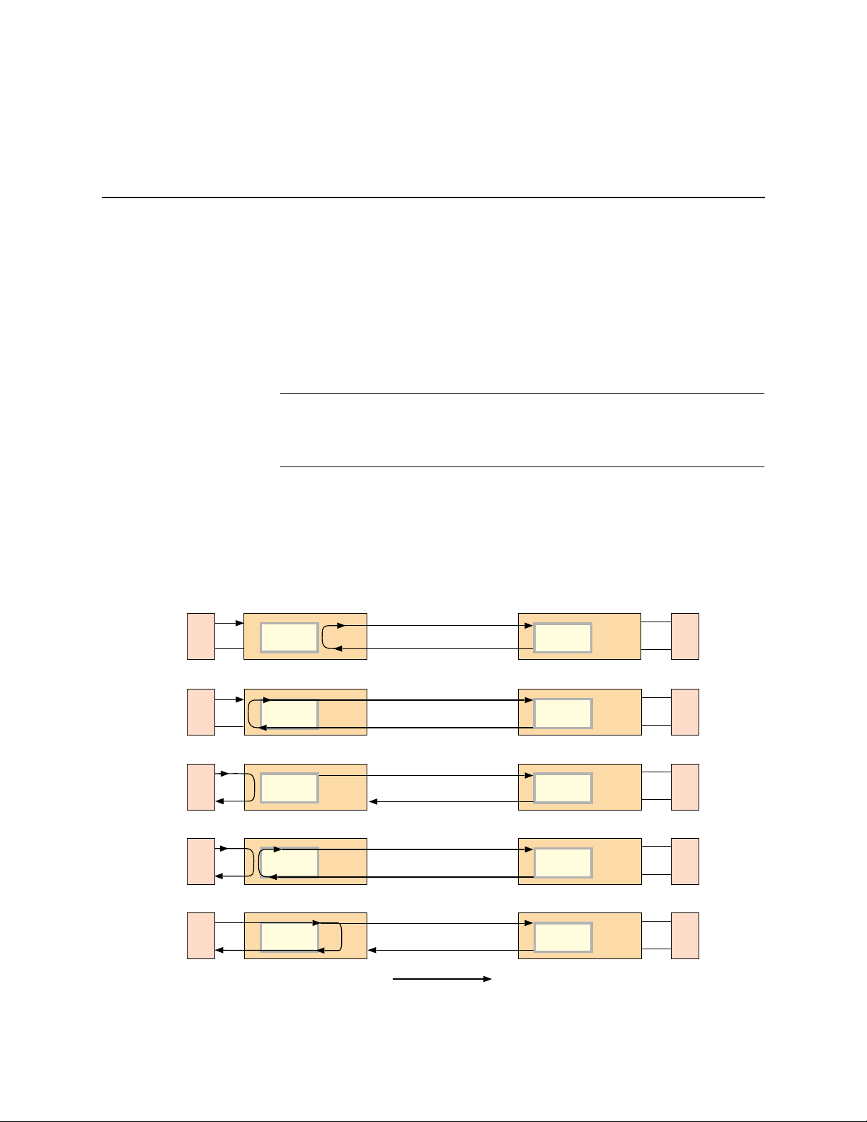
Monitoring and Troubleshooting
When eight zeros are detected in the signal, an intentional bipolar
violation pattern is inserted on the transmit side and removed by
the receive side.
Loopbacks and Test Patterns
Loopbacks are an application module function, and are used to
determine which segment of the network is producing an alarm.
The loopbacks can be installed at the near end or far end of a pointto-point connectio n. Figure 5-2 illustrates which segment of the
point-to-point network is being tested when the near end has the
loopback. The following section describes the loopbacks. These
loopbacks are applicable to T1 and E1 equipment. T3 loopbacks are
defined in the HDM manuals.
NOTE:
A test pattern is a known sequence of bits sent continuously
toward another point in the network. Test patterns are used with
loopbacks to stress the network, and to see if the same pattern is
returned without errors.
Figure 5-2 Near End Loopbacks
Near End Far End
Line
Loopback
Payload
Loopback
Equipment
Loopback
DTE
DTE
Level 1
Equip
Framer
Framer
Framer
All five of the foll owing lo opback s act ivat e the LE D ind icator s
on the front panel o f an NCC, SCC, DCSU, DID CSU, and TAC.
The affected port indicator illuminates amber during t he
loopback.
Framer
Framer
All ones keep-alive
Framer
DTE
DTE
Level 1
Equip
Data Port
Loopback
Repeater
Loopback
5-8 Verilink Access System 2000: The Basics
DTE
DTE
Framer
Framer
Framer
Framer
Data dropped at arrow
DTE
DTE
Page 75

Monitoring and Troubleshooting
Repeater Loopback (RLB)
Line Loopback (LLB)
When a repeater loopback (RLB) is activated, the customer Level 1
equipment and/or DTE is looped on itself through the application
module circuits. The RLB can be used to check the circuit path
from the application equipment through the application module
and back. The applicati on module also passes the equipment
signal to the network. All other loopbacks in progress are
deactivated during an RLB (called local loop in ACP-based cards).
When a line loopback (LLB) is activated, the data received from the
network is transmitted back toward the ne twork. The looped signal
passes through the applicat ion module r epeater so tha t the LLB c an
be used to test the ci r cuit from the far-end applicatio n m o du l e or
telephone company (telco). The application module sends the
network signal or AIS to the equipment, depending on how the
application module is configured option setting.
The LLB can also be activated by sending the industry-standard
inband loop-up code ( 00001) for at least 5 seconds to an
application module. It is then deactivated by sending the
corresponding loop-down c ode (001) for the same time period. In
T1 ESF and E1 circuits, the LLB is also activated and deactivated by
sending bit-oriented messages through the overhead channel.
Payload Loopback (PLB)
Equipment Loopback (ELB)
When a payload loopback (PLB) is activated, the received
information bits (192 bits per frame) are transmitted to the
network. The framing bits (synchronization, CRC-6, and T1 ESF or
E1 data link) originate at the PLB point.
The PLB includes the repeater and signal processing circuits, surge
protection circuits, and Line Build Out (LBO). It provides end-toend testing of the circuit from the far-end application module
through the network line.
The PLB maintains bit sequence integrity for the information bits,
8-bit time slots, frames, an d super-frames. During a PLB, the
application module sends either the network signal (intact) or an
AIS to the equipment, depending on the current application module
configuration setting.
The PLB can be activated and deactivated locally or at the far end
by sending bit-oriented messages over the T1 ESF or E1 data link.
When an equipment loopback (ELB) is activated, the level 1
equipment (PBX, etc.) is looped on itself without going through any
application module circuits. The application module sends either
the equipment signal or an all-ones alarm indication si gnal (AIS) to
Verilink Access Sy stem 2000: The Basics 5-9
Page 76

Monitoring and Troubleshooting
the network, depending on the current application module
configuration settings. The ELB can be activated locally, or at the
far end by a command message on the T1 ESF or E1 data link.
Data Port Loopback (DPLB)
In integrated CSU/DSU modul e s or standalone DSUs, this
bidirectional loo pbac k r etu rns the da ta bac k to t he dat a eq uip ment
and returns the carrier channel signal back to the far end .
Therefore, the DPLB tests the data port cable, th e CSU, and the
carrier channel in both directions.
Test Patterns
AS2000 application modules have several built-in test patterns.
These test patterns are defined in Table 5-4.
Table 5-4 Test Patterns
Option Definition
None This option indicates that no test pattern will be used.
3 in 24 Use 3-in-24 Ones test pattern which consists of three pulses in every 24-bit sequence
QRSS Use Quasi-Random Signal Sequence that limits the signal to a maximum of 15 zeros that
220-1
(10001000 10000000 00000000). This stress test is useful for testing circuits un der
extremely low density conditions. This is mostly useful for T1 AMI.
can be transmitted sequentially. These signals contain a medley of 20-bit words (except
for more than 15 conse cutive 0s). It repeats every 1,048,575 bits. Also, it contains high
density sequences and low density sequences, and sequences that change from low
density to high densit y and vice versa.
This pattern tests circuits for equalization and timing. It is the same as QRSS, but without
the 15 zeros restriction.
1/8 This pattern tests the ability of a circuit to support a pattern having the minimum ones
215-1
All 0s This pattern is composed entirely of framed zeros (00000000).
All 1s This pattern is comprised entirely of framed ones (11111111). It stresses circuits by
density (containing 7 zeros indicating empty pulses and 1 pulse-1000000). It helps
discover a timing recovery problem. This is mostly useful for T1 AMI.
This pattern tests circuits for equalization and timing using an alternate pattern for jitter
testing. The pattern repeats every 32,757 bits.
maximizing power consumption.
5-10 Verilink Access Sy stem 2000: The Basics
Page 77

Performance Monitoring Registers
The statistics logged into the performance monitoring registers is
used to determine how long a fault has existed, and the type,
location, and severity of the fault.
Monitoring and Troubleshooting
Performance Register Definitions
The application module uses error events to derive additional
performance data. This data is stored in registers and can be
retrieved by your management software. The performance data
meets the requirements of AT&T TR-54016, ANSI T1M1.3, and
international standards. Verilink-defined data is also gathered and
stored for operator retrieval. See Table 5-5 for a summary of all
performanc e re gi s t e r acronyms at the end of th i s section.
ESF Error Event (T1 only)
An ESF error event is an extended superfra me t hat co ntains at least
one CRC-6 error event or Out of Frame (OOF) event. ESF error
events are used to derive Errored Sec o nds, Severely Errored
Seconds, Bit Error Rate, Unavailable Signal State, Unavailable
Seconds, and Bursty Erro red Seconds.
Errored Second (ES)
An ES is a second with at least one ESF error event. However,
errored seconds are not counte d when Unavailable Seconds (UA S)
are counted.
Bursty Errored Second (BES)
A bursty errored secon d i s a se cond with 2 to 319 CRC-6 error
events. Bursty errored seconds are not counted when an SES or
UAS is counted.
NOTE:
Bursty Errored Seconds are referred to as Errored SecondsPath (ES) in the ANSI T1 M1.3 performance standard.
Severely Errored Second (SES)
An SES is a second with 320 or more CRC-6 error events, or one or
more OOF events. Severely errored seconds are not counted whe n
UAS are counted.
Verilink Access Sy stem 2000: The Basics 5-11
Page 78

Monitoring and Troubleshooting
Unavailable Signal State (UASS)
The application module retroactively declares a UASS at the onset
of 10 consecutive SESs and clears the UASS at the onset of 10
consecutively non-severely errored seconds. The UASS is
equivalent to a Failed Signal State (FSS).
Unavailable Second (UAS)
The application module declares a UAS for any second during
which a UASS exists. An unavailable second is equivalent to a
Failed Second (FS).
Loss of Frame Count (LOFC)
An LOFC is an accumulation of the number of times an LOF is
declared. A loss of frame is declared when an LOS or OOF occurs
continuously for 2 to 3 seco nds, and is cleared after 10 seconds
without a LOS or OOF event.
Errored Second-Line (ES-L)
An AMI ES-L is a second in which one or more bipolar violations are
received from the network. A B8ZS ES-L is declared when a bipolar
violation is received that is not part of a B8ZS substitution pattern.
Severely Errored Framing Second (SEFS)
An SEFS is a second experiencing one or more events of two or
more frame bit errors in a 3-millisecond period.
Loss of Signal Second (LOSS)
An LOSS is a second in which an LOS condition exists.
Alarm Indication Signal Second (AISS)
An AISS is a second in which the application module receives an AIS
from the network.
Remote Alarm Indication Second (RAIS)
This is a second during which the application module detects an
RAI (Yellow Alarm) from the network.
5-12 Verilink Access Sy stem 2000: The Basics
Page 79

Monitoring and Troubleshooting
Bit Error Rate Alarm Second (BERS)
This is a count of each second during which a network BER alarm
condition existed.
Loss of Frame Second (LOFS)
An LOFS is a count of each second in which the application module
was in a LOF state.
Out of Frame Second (OOFS)
An OOFS is a second experiencing one or more OOF events.
Equipment Low-Density Second (DTED)
This is a second during which a low-density state occurs and the
application module stuffs a one into the signal fr om the equipment
to maintain minimum ones-density on the DS1 network. The
application module also records a DTED whenever it applies a keepalive signal to the network.
Equipment Bit Error Ra te Alarm Second (DBER)
This is a second during whic h the incoming bit error rate from the
equipment exceeds the operator-defined threshold.
Equipment Errored Second
This is the same as the ES previously described, except that it is
detected on the incoming signal f ro m the DS1 equipment.
Equipment UAS, ES-L, and OOFS
These are the same as the UAS, ES-L, and OOFS previously
described, except that they are detected on th e incoming signal
from the DS1 equipment.
Table 5-5 Alarms and Performance Report Acronyms in Alphabetical Order
Acronym T1 E1 Definition Performance/
AIS
AIS-Receiving
••
•
All Ones Indication Signal Received (Red
Alarm)
Receiving All Ones Indication Signal (Red
Alarm)
Alarm/Event/Flag
Alarm Major
Alarm Major
Class
AIS-Sending
•
Sending All Ones Indication Signal (Red
Alarm)
Verilink Access Sy stem 2000: The Basics 5-13
Alarm Minor
Page 80

Monitoring and Troubleshooting
Acronym T1 E1 Definition Performance/
AISS
BES
BPV
BPVs
CFA
CRC-4
CRC-6
CSES
DM
EFS
ES
ESF
FAS
FASE(R)
••
•
•
••
••
••
•
•
•
•
•
••
•
•
•
Alarm Indication Signal Second Performance Minor
Bursty (E1: Block) Errored Second Performance Minor
Bipolar Violation Thresh old Alarm Alar m —
Monitor Bipolar Violations Performance —
Carrier Failure Alarm Alarm/Threshold Major
Cyclic Redund ancy Check 4 Error Ev ent Error Event Mi nor
Cyclic Redundancy Check 6 Error Event (T1
ESF only)
Consecutively Severely Errored Seconds Performance -—
Degraded Minutes Performance —
Errored Free Seconds Performance —
Errored Secon d Performance —
ESF Error Eve nt, T1 ESF only Error Event —
Frame Alignment Signal Event Minor
Frame Alignment Signal Error (Rate) Performance Mjr/Mn
Alarm/Event/Flag
Error Event Minor
Class
FE
FEBE
LOC
LOCA
LOF
LOFA
LOFS
LOMA
LOMA/DE-CAS
LOP
LOS
LOSS
LSS
MAS
NFAS
OOF
•
•
••
•
••
••
••
•
•
••
••
••
••
•
•
••
Framing Bit Error Flag —
Far End Block Error when CRC-4 is enabled Error —
Loss of Clock Alarm Critical
Loss of CRC Multiframe Alignment Alarm Minor
Loss of Frame Alarm Alarm Major
Loss of Frame Alignment Alarm Major
Loss of Frame Second Performance —
Loss of TS16 Multifr a m e Alignment Alarm Major
Loss of Distant End CAS Multiframe
Alignment
Loss of Power Alar m Major
Loss of Signal Alarm Major
Loss of Signal Second Performance —
Loss of Synchronization Source Alarm —
TS16 Multiframe Alignment Signal Alarm Minor
Non-frame Alignment Signal Alarm Major
Out of Frame Event Event —
Alarm —
OOFS
RAI
RAI-Receiving
5-14 Verilink Access Sy stem 2000: The Basics
••
••
••
Out of Frame Second Performance —
Yellow Alarm Indication Signal Received Alarm —
Receiving Yellow Alarm Indication Signal Alarm —
Page 81

Monitoring and Troubleshooting
Acronym T1 E1 Definition Performance/
RAIS
SEF
SEFS
SES
UAS
UASS
Performance Data Processing
••
••
••
••
••
••
Sending Yellow Alarm Indication Sign al Alarm —
Severely Errored Fram in g Ala rm Alarm —
Severely Errored Fra min g Sec ond Performance —
Severely Errored Se co n d Performance —
Unavailable Second Performance —
Unavailable Signal State Performance —
The following sections list the data processing for the AT&T TR54016, ANSI TIM1.3, Verilink, and equipment-side performa nce
Alarm/Event/Flag
data.
NOTE:
The NCC and TAC store pa rt of the 24-hour performance
data in two separate register sets. One set is for the customer
(user) and the other set is for the other provider (telephone
company). Both the user and telephone company operators
can access and read the registers, but each can only reset
their own register sets. Only the TR-54016 registers are in
the carrier set.
Class
AT&T TR 54016
Performance Data
Processing
ANSI TIM1.3
Performance Data
Processing
The following AT&T performance data is stored in telephone
company registers on the application module:
•
LOFC Register
•
BES Register
•
UAS Register
•
SES Register
•
ES Register
•
24-hour Data Register (of all above data)
The following ANSI TIM1.3 performance data is stored in user
registers on the application module:
•
ES-L Register
•
SEFS Register
•
SES Register
•
ES-B Register
•
LOSS Register
•
UAS Register
•
AISS Register
Verilink Access Sy stem 2000: The Basics 5-15
Page 82

Monitoring and Troubleshooting
•
ES Register (equivalent to ANSI ES-P Register)
•
24-hour Data Register (of all above data)
Verilink
Performance Data
Processing
Equipment Signal
Performance Data
Processing
The following Verilink performance data is stored in network
registers on the application module:
•
RAIS Register
•
LOFS Register
•
BERS Register
•
OOFS Register
•
24-hour Data Register (of all above data)
The following Verilink performance data is stored in equipment
signal performance registers on the application module:
•
DTED Register
•
ES-L Register
•
OOFS Register
•
DBER Register
•
UAS Register
•
ES Register
•
24-hour Data Register (of all above data)
Power Failure
DC Power
The Access System 2000 shelf unit typically has two power
supplies for redundant operation. This arrangement maintains T1
network transmission service if one of the power supplies fails.
Each Dual-line Shelf can use two redundant 115 Vac or 48 Vdc
power supplies. If HDM 2180 or HDM 2182 modules are used in a
Dual-line shelf, use of two power supplies is suggested.
If a Multi-line Shelf loses power, the front panel power LED of the
associated power supplies will go out, and all LEDs on the other
modules go out. If this condition exists, check the power source.
If one power supply fails in a Multi-line Shelf powered by -48 Vdc,
check for a blown fuse in the fuse panel. Check for -48 Vdc at the
backplane for that po wer supply. The -48V and battery return
connections are made at terminal strip TB1 in back of the shelf.
5-16 Verilink Access Sy stem 2000: The Basics
Page 83

Monitoring and Troubleshooting
The input DC voltages can be measured at J14 (power supply A) or
J15 (power supply). If the power supply input voltage is correct,
measure the output voltages at the front panel test jacks. The 5V
point should output 5.5 Vdc and the 12 V point should output 12
Vdc.
If the shelf backplane has DC power, replace the associated DC
power supply. Check the power source and ground wiring from
TB1.
AC Power
If an AC power supply fails, c heck the power cord con nection to the
AC outlet. If this connec ti on is good, verify that th e AC o utl et is
providing power. If the power source is good, replace the power
supply.
NOTE:
Figure 5-3 illustrates a basic AS2000 fault isolation tree.
When operating in an AC power environment, give strong
considerat io n to con necting one powe r su pply to a UPS, and
the other power supply directly to local commercial power.
Verilink Access Sy stem 2000: The Basics 5-17
Page 84

Monitoring and Troubleshooting
Figure 5-3 System Fault Isolation Flow
AS2000 Module
Fault Isolation
Check System
Power
Verify
Self Test
Check System
Configuration
Perform NET
loopback plug test
(red NET LED)
Are any LEDs
illuminated
Yes
Did all modules
pass self test
Yes
Is AS2000
configured properly
Yes
Did system pass
NET loopback
No
No
No
No
Yes
Check Power
Supply Voltage
Check Module
and CIM
Installation
Reconfigure
AS2000
Notify
Telco
Is power
supply providing
correct voltages
Yes
No
Power Supply
Check Local
Replace
Module
End
Are all modules
installed properly
Yes Yes
Is AS2000
operating properly
No
Reinstall
No No
Module
End
Yes
End
Is local
power providing
correct voltage
Yes
Replace
power supply
Did module
pass self test
End
No
Correct
Local Power
Replace
Module
End
End
Perform application
equipment loopback
test (red EQUIP or
Data Port LED)
Replace
Module
Check EQPT Port
With Loopback
If
Check Data Port
With Loopback
Plug
Te st
End
Did system pass
loopback plug test
Yes
Did system pass
loopback test
No
Replace
Module
No
Check application
associated cables
Yes
Replace
Module
equipment and
End
End
End
5-18 Verilink Access Sy stem 2000: The Basics
Page 85

Monitoring and Troubleshooting
System Fault Isolation
Check System
Power
Verify Self Test
The system flow in Figure 5-3 is intended for system start-up
problems. Troubleshooting an individual system module requires
that module’s documentation.
An indication of system power problems is the lack of illuminated
LEDs on any/all of the modules. This indication is caused by faulty
power supplies, faulty modules, or lack of local power. To isolate a
system power fault:
1. Check local power voltages.
If local power is normal:
2. Check power supply voltage.
If the power supply voltages are out of tolerances:
3. Replace th e affect e d powe r supp ly.
When power is applied to t he system, the system m odules perform
a self-test. If any module fails self test:
1. Verify that the rear module is th e valid type for the front
module being used.
Check System
Configuration
NET Loopback
2. Check the module and associated rear connector module. If
the module ap pe a r s to be good:
3. Reinstall the module. If the module fails self-test:
4. Replace the module and verify self-test.
Most AS2000 problems are related to system configuration. The
system must be properly configured to meet specific site operating
parameters and both ends of the p oint-to-poi nt circuit need to have
the same configuration. To check system configuration, refer to
the individual module’s documentation.
A loopback plug can be used to determine whether o r not a
application module is defective. If the Net LED is red, install a
loopback plug and perform a loopback test.
1. If the Net LED changes from red to green, notify the telco to
check for a line problem.
2. If the Net LED stays red, recheck system configuration.
3. If the problem is not corrected, replace the affected module.
Verilink Access Sy stem 2000: The Basics 5-19
Page 86

Monitoring and Troubleshooting
Perform
Application
Equipment
Loopback
CSU Mode
Troubleshooting
An equipment or data port loopback checks the cable integrity
between the AS2000 system and customer equipment. If a
equipment or data port LE D is red , inst all a loopback plug and
perform a loopback test.
1. If the Eqpt or Data port LED is red, install a loopback plug in
the EQ port.
If the Eqpt LED or Data port changes from red to green:
2. Check application equipment and associated cables.
If the Eqpt or Data port LED stays red:
3. Replace the module, CIM, or both.
The Equipment and Net LE Ds of the appl ication module monitor the
status of the incoming T1 signals, from both the equipment and
network sides of the application module.
During normal operation both LEDs are green, indicating the
application module is receiving acceptable signals from both
directions. (T1 only: If the application modules are used with DIUs
in a T1 multiplexer mode, the Equipment LED remains green).
A red Net LED indicates a failure in the incoming direction from the
network:
•
Excessive bipolar violations (BPVs) or CRC errors in the
incoming signal.
•
Loss of the incoming signal (LOS) from the network (faulty
cabling from the network interface, or faulty circuit or
application module on the network).
•
The application module cannot frame up on the incoming
signal (LOF condition).
•
A Yellow Alarm (RAI) was received from the far-end application
module.
The Stat LED of the application module is red when any of the
above conditions exists. The LED indicates that an application
module alarm state was reported to the management software (if
enabled).
If the Net LED and Stat LED are both red, troubleshoot the telco
circuit and the application module at each end. Use the loopback
plugs, testing the signal-sending functions of the application
modules, isolating the fault to the application modules or the
circuit.
A red Equipment LED on an application module, indicates trouble
with the local equipment. These faults are:
•
Excessive bipolar violations (BPVs) or CRC errors in the
incoming signal.
5-20 Verilink Access Sy stem 2000: The Basics
Page 87

Monitoring and Troubleshooting
•
The application module cannot frame up on the equipment
signal (LOF condition).
•
Detection of a Yellow Alarm.
•
LOS, low ones-density, or excessive frame-bit error detection
in the incoming signal.
Check the operation of the eq uipment connec ted to the application
module. Check the cabling from the equipment to the rear
connector module.
If the application module can not frame up on the signal from the
equipment, verify that the local and far-end application modules
are configured correctly. If the appl ication modules are configured
correctly, troubleshoot the local equipment.
The Stat LED indicates the current application module status. The
Stat LED is green or not illuminated during normal application
module operation (if the application module is not accessed by an
operator and is not in an alarm st ate).
If the Stat LED is red, and the Equipment (EQPT) or Net LEDs are not ,
the application module alarm condition is cleared, but the BER, ES,
ES-L, or UAS thresholds have not been cleared. The STAT LED will
go out after 15 minutes, and will pass with no new alarm
conditions.
Verilink Access Sy stem 2000: The Basics 5-21
Page 88

Monitoring and Troubleshooting
5-22 Verilink Access Sy stem 2000: The Basics
Page 89

Appendix
A
Compliance Statements
AS2000 modules comply with the applicable re quirements and
specifications described in the following sections.
Line Aggregate Compliance
Certain Verilink modules used with the AS2000 system meet or
exceeds the following E1 aggregate line requirements as specified
by the International Telegraph and Telephone Consultative
Committee (CCITT):
G.703:
•
Interfaces (Geneva, 1972 thro ugh amendments Geneva, 1991)
G.704:
•
Secondary Hierarchical Levels (Malaga—Torremolinos, 19 84
through amendments Geneva, 199 1)
G.706:
•
Procedures Relating to Basic Frame Structures Defined in
Recommendation G.704 (Melbourne, 1988 thro ugh
amendments Geneva, 1991)
Physical/Electrical Characteristics of Hierarchical Digital
Synchronous Frame Structures Used at Primary and
Frame Alignment and Cyclic Redundancy Check (CRC)
G.732:
•
•
•
T1 aggregate line requirements:
•
•
•
•
Characteristics of Primary Pulse Code Modulation (PCM)
Multiplex Equipment Oper ating at 2048 Kbit/s (Geneva, 1972
through amendments Geneva, 198 8)
G.823:
The Control of Jitter and Wander Within Digital Networks
Which Are Based on the 2048 kilobits Hierarchy (Malaga—
Torremolinos, 1984; amended at Melbourne, 1988)
G.826:
Performance Parameters for Digital Networks (Genev a,
1992)
ACCUNET
(December 1990)
ANSI T1.103, 403, and 406
Telecommunications Network to Customer Installation DS1
Metallic Interface (March 1995)
AT&T 54016
1986)
E1A/T1A Standar
Equipment for DS1 Service (March 1989)
® T1.5 Service Description and Interface Specification
—American National Standard for
—Data Communications Technical Reference (May
(E1A/T1A—547) Network Channel Terminal
Verilink Access Sy stem 2000: The Basics A-1
Page 90

Compliance Stat ements
Data Interface Specifications
Mean Time Between Failure
The following data interface specifications conform with CCITT
and ISO standards:
X.21 (CCITT):
•
and Data Circuit Terminating Equipment (DCE) for
Synchronous Operation on Public Data Networks (Geneva,
1972 through amendments Melbourne, 1988), which supports
only the lease line mode
V.35 (CCITT), ISO 2593:
•
interface connector and pin assignments (Second edition—
1984-02-01)
RS-449:
•
for Data Terminal Equipment and Data Circuit–Termi nating
Equipment Employing Serial Binary Data Interchange (EIA–
449—1 Electronic Industries Association, Washington, D.C.,
1980).
EIA 530:
•
Equipment and Data Circuit–Terminating Equipment (EIA–530
Electronic Industries Association, Washington, D.C., 1987).
The mean time between failure (MTBF) calcu lations comply with the
following specification:
Bellcore TR-00033 2:
•
Electronic Equipment. The mean time between failure must be
80,000 hours with a continuous duty cycle.
Interface Between Data Terminal Equipment ( DTE)
Data communicati on—34-pin DTE / DCE
General Purpose 37–Position and 9–Position Interface
High Speed 25–Position Interface for Data Terminal
Reliability Prediction Procedure for
British Approvals Board of Telecommunications (BABT)
The following statements of compliance are presented in
accordance with the British Approvals Board of
Telecommunicati ons (BABT) as per the Offi ce of
Telecommunicati o ns (OFTEL) document OTR001 dated March 1988
and the following OTR001 appendices:
•
Annex E: Technical Requirements for Signaling Converters
with Ports, TR3AAD, June 1989
•
Annex F: Technical Requirements for Multiplexers with
Ports,TR3AAF, June 1989
•
Annex E: Technical Requirements for Echo Cancelling Devices,
MP2AAH, June 1989
•
TBR 13: January 1996
•
EN60950:1992/A2:1993, IEC950:1 991/A2:1993, Natio nal
Deviations, TS0001:1993, AS/NZS3260:1993, EN410 03:1993
•
ITU Recommendation G.703/4 (1991)
A-2 Veri link Access System 2000: The Basics
Page 91

Compliance Statements
•
PD 7024:1994
•
Svensk SS 63 63 34: November 1991
•
BAPT 221 ZV MU 9a/b September: 1993
•
AUSTEL TS016: 1994
•
CTR12 (Commission Decision of 18 July 1994 on a common
technical regulati on for at tachment requirement s for tech nical
equipment interface for ONP 2048 kbit/s digital unstructured
leased line: 94 /470 /E C OJ N o. L19 4 V ol. 37 da ted 2 9 J uly 19 94)
Cabling
The following statement(s) comply with section X.17 of OFTEL
OTR001 on page X.17 (1) TR2AAC:
For electrical requirements for cabling connections to the network
1. The cabling used with this equipment shall have a maximum
attenuation of 6 dB @ 1024 KHz.
2. The attenuation characteristics of the associated cable shall
follow a
providing a declaration stating compliance with the above
specifications.
For signal earthing of network interfaces:
1. A facility has been provided to enable the outer conductor of
the associated network cable connection to be disconnected
from the private branch exchange (PBX) functional earth.
2. The transmit cable connector interface has an associated
jumper on the pri nted circuit board assembly used to connect
or disconnect the outer conductor of the network cable from
functional earth.
3. The receive cable connector interface has an associated
jumper on the pri nted circuit board assembly used to connect
or disconnect the outer conductor of the network cable from
functional earth.
root f
law. The cable supplier is responsible for
Required Information for Instructions and Testing
The following statement(s) comply with section 2 of Annex F in
OFTEL OTR001 on page 2 (2) TR3AAF.
1. No analog network required.
2. Port-to-port losses for DIDCSU call paths are not applicabl e .
3. Input and output relative levels are not applicable.
4. The DIDCSU will pass channel associated signaling (CAS). It
will not interpret the channel associated signaling data.
Verilink Access Sy stem 2000: The Basics A-3
Page 92

Compliance Stat ements
5. Disabling AC or DC signaling detectors are not applicable.
6. The DIDCSU is not to be connected to cabling that requires
over voltage protection.
7. The round trip delays through the DIDCSU are as follows:
s
•
Minimum—125
•
Typical—250
•
Maximum—500
µ
s
µ
s
µ
Tolerance to Wander
The following statement(s) comply with OFTEL OTR001 on page
W.4 (2) TR2AAB:
Tolerance to wander is provided by the E1 framer device and the
line interface device.
•
The line interface device has a 32-bit buffer.
•
The framer device has a two-frame elastic buffer that provides
a buffer sufficient to tolerate 125 microseconds of wander.
This exceeds the buffer size of 18 microseconds required in
W.4.3.3.
Certifications and Compliance
The Verilink Dual-line Shelf power supply (PWR 2940) complies
with the following specifications and agencies:
•
Underwriters Laboratory (UL)
•
Electrical Safety (UL 1950 no deviation)
•
Telephone Equipment (UL 1459 second edition)
•
Federal Communications Commission (FCC) Part 15
•
FCC Part 68—FCC Rules for Registration of Telephone
Equipment (October 1992)
•
Canadian Standards Association (CSA)
•
Electrical Safety (CSA C22.2 #950)
•
Electromagnetic Inter ference (CSA C108.8-M 1983)
•
DOC
•
European Community
•
Telecommunication Terminal Equipment Directive
(91/263/EEC)
•
Low Voltage Directive (73/23/EEC)
•
EMC Directive (89/336/EEC)
•
Electrical Safety (EN 60950/IE 950)
A-4 Veri link Access System 2000: The Basics
Page 93

Compliance Statements
•
Network Safety (EN 41003/IEC 105)
•
Emissions (EN 55022/CISPR 22)
•
Immunity (EN 55024/IEC 801) Part 2, 3, 4, 5, and 6
•
British Approvals Board for Te lecom m u nic at ions (BAB T)
•
Electrical Safety (BS 6204/EN 60950)
•
Network Safety (BS 6301/BABT 340/EN 41003)
•
Institute of Electrical and Electronics Engineers (IEEE)
Surge Protection (IEEE C62.41-1991)
Verilink Access Sy stem 2000: The Basics A-5
Page 94

Compliance Stat ements
A-6 Veri link Access System 2000: The Basics
Page 95

Appendix
B
Acronyms
System Cables
This appendix contains a list of cable lead acronyms used
throughout the AS2000 manuals. Additionally, there is an
illustrated cable part listing with pinouts and part numbers for
each cable.
The following acronyms are used in this manual:
Acronym Description
CGND Chassis Ground (Shield)
TXD Transmit Data
RXD Receive Data
RTS Request to Send
CTS Clear to Send
DSR Data Set Ready
DTR Data Termi nal Ready
DCD Data Carrier Detect
XTC Transmit Signal Element Timing (DTE)
TXC Transmit Signal Element Timing (DCE)
RXC Receive Signal Element Timing (DCE)
LLB Local Loopback
RLB Remote Loopback
TM Test Mode
GND Signal Ground
SD Send Data
RD Receive Data
SG Signal Ground
Verilink Access Sy stem 2000: The Basics B-1
Page 96

System Cables
Illustrated Parts List
This section contains the illustrated parts list with pin-outs. This
listing also contains part numbers and cable lengths.
Table B-1 Illustrated Parts List—Cables
Description Part Number Length Illustration
RS-232 Craft Cable 458-501788-00 8 8 ft/243.8 cm
RS-232 Modem Cable
(Remote Dial Craft
Configuration)
V.35 Adapter Cable (DCE)
(typical)
V.35 Adapter Cable (DTE)
(for tail circuits)
X.21 Adapter Cable (DCE)
(typical)
X.21 Adapter Cable (DTE)
(for tail circuits)
RS-449 Adapter Cable
(DCE) (typical)
RS-449 Adapter Cable
(DTE) (for tail circuits)
EIA 530 Adapter Cable
(DCE/DTE)
Adapter Cable, DCE
pinout (Continue d )
Adapter Cable, DTE
pinout (Continue d )
RJ-48C/DB-25 Network
Management Cable
RJ-48/RJ-48 Crossover
Cable (for management
only)
RS-422 8-pin DIN Daisy
Timing Cable
8-pin DIN to Pigtail
Timing Cable
8-pin DIN to 8-pin DIN
Timing Cable
8-pin DIN to RS-422
Timing In Cable
TTL Timing In and Daisy
Cable
Timing Cable Pinouts
458-501764-008 8 ft/243.8 cm
458-501594-001
458-501594-002
458-501594-101
458-501594-102
458-502047-001 4 ft/121.9 cm
458-502047-101 4 ft/121.9 cm
458-502059-001 4 ft/121.9 cm
458-502059-101 4 ft/121.9 cm
458-502045-001 4 ft/121.9 cm
458-502312-008 8 ft/243.8 cm
458-502313-008 8 ft/243.8 cm
458-501783-012 12 ft/365.8 cm
458-501784-006 6 ft/182.88 cm
458-501786-003
458-501786-006
458-501787-012 12 ft/365.8 cm
458-501903-006 6 ft/182.9 cm
3.5 feet/106.7 cm
2 ft / 61.0 cm
3.5 feet/106.7 cm
2 ft/61.0 cm
3 ft/91.4 cm
6 ft/182.9 cm
Figure B-1, “RS–232 Craft Cable”
Figure B-2, “RS–232 Modem
Cable (Remote Dial Craft
Configuration)”
Figure B-3, “V.35 Adapter Cable
(DCE)”
Figure B-4, “V.35 Adapter Cable
(DTE)”
Figure B-5, “X.21 Adapter Ca b le
(DCE)”
Figure B-6, “X.21 Adapter Ca b le
(DTE)”
Figure B-7, “RS-449 Adapter
Cable (DCE)”
Figure B-8, “RS-449 Adapter
Cable (DTE)”
Figure B-9, “EIA 530 Adapt er
Cable (DCE/DTE)”
Figure B-10, “EIA 530 Adapter
Cable (DCE)”
Figure B-11, “EIA 530 Adapter
Cable (DTE)”
Figure B-12, “RJ-48C/DB-25
Network Management Cable
(ACE cards only)”
Figure B-13, “RJ-48/RJ-48
Crossover Cable (ACE cards
only)”
Figure B-14, “RS–422 + Daisy
Timing Cable”, Figure B-15, “RS449/422 Timing Cable
(continued)”
Figure B-16, “8-Pin Din to Pigtail
Timing Cable”
Figure B-17, “8-Pin Din—8-Pin
Din Timing Cable”
Figure B-18, “8-Pin to RS-422
Timing In Cable”
Figure B-19, “TTL Timi ng In +
Daisy Cable”
Figure B-20, “Timing Cable
Pinouts (continued)”
B-2 Verilink Access System 2000: The Basi cs
Page 97

Description Part Number Length Illustration
120 Ohm, DE-09
458-502649-008 8 ft/243.8 cm
Network Crossover Cable
RJ-48/DB-15 T1 100
Ohm Network Cable
458-501768-008
458-501768-020
458-501768-050
458-501768-100
RJ-48/RJ-48 T1 100 Ohm
Network Cable
458-501769-008
458-501769-015
458-501769-020
458-501769-030
458-501769-050
458-501769-100
Figure B-1 RS–232 Craft Cable
Part Number 458-501788-008 (8 ft.)
8 ft/243.8 cm
20 ft/609.6 cm
50 ft/1524 cm
100 ft/3048 cm
8 ft/243.8 cm
15 ft/457.2 cm
20 ft/609.6 cm
30 ft/914.4 cm
50 ft/1524 cm
100 ft/3048 cm
System Cables
Figure B-21, “120 O HM, DE-09—
DE-09 Network Cr ossover
Cable”
Figure B-22, “RJ-48/DB-15 T1
100 OHM Network Cabl e”
Figure B-23, “RJ-48/RJ-48 T1
100 OHM Network Cabl e”
6 PIN MINI
MOD
6
1
P1
1
2
RX
TX
SGND
: Contact Verilink Technical Assistance Center for a craft cable with a DB9 connector.
Note
3
4
5
6
DRAIN
DTE DTE
(N/C Indicates no connection
1. The Craft cable provides a connection between an AS2000 module and a dumb
ASCII terminal. This cable is required to access the CraftI (ASCII) interface used to
configure the module, and to monitor network performance.
DRAIN
DB-25
NC
NC
14
1
13
FEMALJ1
J1P1
2
3
7
25
TX
RX
SGND
2. This cable is used on all Verilink node controllers and ACE cards.
Verilink Access Sy stem 2000: The Basics B-3
Page 98

System Cables
Figure B-2 RS–232 Modem Cable (Remote Dial Craft Configuration)
Part Number: 458-501764-008 (8 ft.)
6 PIN MINI
MOD
6
1
P2
RX
TX
DB-25
P1
P1P2
1
2
3
4
NC
NC
3
2
RX
TX
13
MALE
25
14
1
SGND
5
6
DRAI
DTE DCE
(N/C Indicates no connection
DRAIN
7
SGND
B-4 Verilink Access System 2000: The Basi cs
Page 99

Figure B-3 V.35 Adapter Cable (DCE)
Part Number: 458-501594-00X
System Cables
FEMALE
14
26
CGN
13
RTS
CTS
DSR
DTR
LLB
RLB
TXD
TXD
RXD
RXD
XTC
XTC
RXC
RXC
TXC
TXC
DCD
TM
GND
RSVD
PIN 1
MALE
(A)
(B)
(A)
(B)
(A)
(B)
(A)
(B)
(A)
(B)
P1
26
5
18
16
3
22
9
2
15
4
17
12
25
10
23
11
24
7
20
1
14
P1
P2
DCE
P2
DRAINDRAIN
A
CGND
WHT/TAN
TAN/WHT
WHT/BRN
BRN/WHT
WHT/PNK
PNK/WHT
WHT/ORG
ORG/WHT
WHT/YEL
YEL/WHT
WHT/GRN
GRN/WHT
C
D
E
H
K
L
N
P
S
R
T
U
W
(A)
(B)
(A)
(B)
(A)
(B)
RTS
CTS
DSR
DTR
(LL)
LL
RL
SD+
SD-
RD+
RD-
SCTE+
SCTEWHT/BLU
BLU/WHT
WHT/VIO
VIO/WHT
WHT/GRY
GRY/WHT
V
X
Y
AA
F
NN
(A)
(B)
(A)
(B)
SCR+
SCR
SCT+
SCT-
RLSD
TM
TAN/BRN
C
/
N
BRN/TAN
N
B
C
/
SG
GND
13
(N/C Indicates no connection
P2
A
B
D
C
E
K
P
CC
HH
MM
F
J
L
N
R
T
U
V
X
Y
Z
BB
DD
FF
JJ
LL
NN
H
M
S
W
AA
EE
KK
Verilink Access Sy stem 2000: The Basics B-5
Page 100

System Cables
Figure B-4 V.35 Adapter Cable (DTE)
Part Number: 458-501594-101 (3 ft.- 6 in)
P1
14
26 13
PIN 1
MALE
P2
DTE
MALE
CGND
RTS
CTS
DSR
DTR
LLB
RLB
TXD
TXD
RXD
RXD
XTC
XTC
RXC
RXC
DCD
TM
GND
RSVD
GND
(A)
(B)
(A)
(B)
(A)
(B)
(A)
(B)
P1
13
12
25
10
1
14
26
5
18
16
3
22
9
2
15
4
17
23
7
20
DRAINDRAIN
WHT/TAN
TAN/WHT
WHT/BRN
BRN/WHT
WHT/PNK
PNK/WHT
WHT/ORG
ORG/WHT
WHT/YE
YEL/WHT
WHT/GRN
GRN/WHT
WHT/BLU
BLU/WHT
N/C
N/C
WHT/VIO
VIO/WHT
N/C
N/C
WHT/GRY
GRY/WHT
TAN/BR N
N/C N/C
BRN/TA
(N/C Indicates no connection
P2
P2
A
D
C
H
E
F
NN
R
T
P
S
V
X
U
W
L
N
B
(A)
(B)
(A)
(B)
(A)
(B)
(A)
(B)
CGND
CTS
RTS
DTR
DSR
RLSD
TM
RD+
RD-
SD+
SD-
SCR+
SCR-
SCTE+
SCTE-
LL
RL
SG
A
DD
NN
B
F
L
R
V
Z
JJ
T
X
BB
FF
LL
C
D
E
H
J
N
M
P
S
U
W
Y
AA
CC
EE
HH
KK
MM
B-6 Verilink Access System 2000: The Basi cs
 Loading...