

Page 1

Verilink APS 2000
User Manual
August 1999
P/N 880-502411-001-D
Page 2

Copyright Notice
Copyright 1999 Verilink Corporation. All rights reserved.
This document does not create any express or implied warranty about Verilink or
about its products or services. Verilink’s sole warranty is contained in its product
warranty. The end-user documentation is shipped with Verilink’s products and
constitutes the sole specifications referred to in the product warranty. Verilink has
made reasonable efforts to verify that the information contain ed h erein is accurate,
but Verilink assumes no responsibility for its use or for any infringement of patents
or other rights of third parties that may result. The customer is solely responsible
for verifying the suitability of Verilink’s pro ducts for its use. Specifications are
subject to change without notice.
Trademarks
FCC Requirements
Verilink is a registered trademark of Verilink Corporation. Access System 2000,
WANscope, VeriStats, and FrameStart are trademarks of Verilink Corporation.
Any named prod ucts herein are trademarks of their respective companies.
This equipment has been tested and found to comply within the limits for a Class A
digital device pursuant to Par t 15 of the Federa l Communic ations C ommissio n (FCC)
rules. These limits are designed to pro vide protection against harmful interference
in a commercial environment.
This equipment generates, uses, an d can radiate radio frequency energy and, if not
installed and used in accord ance with the user manual, can cause harmful
interference t o radio communications.
There is no guarantee that interference will not occur in a particular installation. If
this equipment causes harmful interference to radio or television reception—which
can be determined by turning the equipment off and on—try to correct the
interference by one or more of the following measures:
Reorient or relocate the receiving antenna.
•
Increase the separation between the equipment and receiver.
•
Connect the equipment into an outlet on a circuit different from that to whi c h
•
the receiver is connected.
Consult the dealer or an experienced radio/TV technician for help.
•
This equipment complies with Part 68 of the FCC Rules. On the rear, side or bottom
of the unit is a label that contains the FCC registration number and other
information. If requested, provide this information to the telephone company.
All direct connecti ons to the ne twork lines m ust be made usi ng standard plugs
•
and jacks (compliant with Part 68). The following tables list the applicable
registration jack universal order codes (USOCs), facility interface codes (FICs),
and service order codes (SOC s). These are required to order service from the
telco.
For T1 interfaces:
Port ID REN/SO C FIC USOC
1.544 Mbit/s SF
1.544 Mbit/s SF, B8ZS
1.544 Mbit/s ANSI ESF
1.544 Mbit/s ANSI ESF, B8ZS
For DDS interfaces:
Port ID REN/SO C FIC USOC
56 kbit/s
64 kbit/s
If the unit appears to be malfunctioning, inform the telco and disconnect it
•
from the network lines until the source of trouble is determined to be your
equipment or the telephone line . If your equipment needs repair, it should
not be reconnected until it is repaired.
ii Verilink APS 2000 User Ma nual
6.0N 04DU9 -BN
6.0N 04DU5 -56
04DU9 -DN
04DU9 -1KN
04DU9 -1SN
04DU5 - 64
RJ-48C jack
RJ-48S jack
Page 3

The unit has been designed to prevent harm to the network. If the telephone
•
company finds that the equipment is exceeding tolerable parameters, it can
temporarily disconnect service. In this case, the telephone company will
provide you advance notice if possible.
If the telephone company alters its equipment in a manner that can affect the
•
use of this device, it must give you warning so that you have the opportunity
to maintain uninterrupted service. You will be advised of your right to file a
complaint with the FCC.
No customer is authorized to repair this equipment, regardless of warranty
•
status. All repairs must be performed by Verilink or an authorized agent. It is
the responsibility of users requiring service to report the nee d for service to
Verilink or to one of our authorized agents.
Lithium Battery
English
Français
The lithium battery referred to in the following notices is contained inside the clock
chip.
DANGER!
The battery can explode if incorrectly replaced! Replace only with the same or
equivalent type recommended by the manufacturer. Dispose of used batteries
according to the manufacturer’s instructions.
DANGER!
To avoid electrical shock in case of failure, the power supply must be installed
by a professional installer. The terminal labeled with the ground symbo l ( )
on the power supply must be connected to a permanent earth ground.
CAUTION!
Interconnecting circuits must comply with the requirements of
EN60950:1992/A2:1933 Section 6.2 for telecommunications network voltages
(TNV) circuits.
ATTENTION!
Une explosion peut se produire si la batterie est remplacée d’ une façon incorrecte! Remplacez-la seulement avec le même modêle de batterie ou un modèle
équivalent selon les recommendations de manufacture. Disposez de les batteries usées selon les instructions de manufacture.
ATTENTION!
Pour éviter choc électrique en cas de insuccès, la provision de pouvoir doit êtré
installé par un installeur professionnel. Le terminal de la provision de pouvoir,
marqué du symbol de terre, ( ) doit connecté à un circuit de terre permanent.
ATTENTION!
Les circuits doivent êtré interconnectés de manière à ce que l’ équipement
continue a êtré en agrément avec “EN60950:1992/A2:1933, Section 6.2, pour les
circuits de voltage de liaisons d’ échanges (réseau) par les télécommunications
(TNV),” après les connections de circuits.
Españole
PELIGRO!
La bateria puede exp lotar si s e reempla za incorr ectamente. Reemp lace la bateri a
con el mismo tipo de bateria ó una equivalente recomendada por el manufacturero. Disponga de las baterias de acuerdo con las instrucciones del manufacturero.
PELIGRO!
Para evitar contacto con circuitos que electrocutan, la fuente de alimentación
debe ser instalada por un técnico profesional. La terminal de la fuente de alimentación marcada con el símbolo de tierra ( ) debe ser con ectada a un cir-
Verilink APS 2000 User Manual iii
Page 4

cuito de vuelta por tierra permanente.
CIRCUITOS A INTERCONECTARSE
Circuitos que se int erc on ecta n a la re d de telecomunicaciones deben h acer se d e
tal manera que cumplan con los requisitos estipulados en las especificaciones
“EN60950:1992/A2:1933, Sección 6.2, para los voltages de circuitos
interconnectados a la Red de Telecomunicaciones (TNV),” despues de terminar
las connecciones entre los circuitos.
Deutsch
Canadian
Requirements
VORSICHT!
Explosionsgefahr bei unsachgemäßem Ersetzen der Batterie! Batterie gleichen
Typs und gleicher Qua lität ben utzen, wie v om Hersteller empfohlen. Entsor gung
der Batterie nach Anweisung des Herstellers!
VORSICHT, GEFAHR!
Um keinen Schlag zu erhalten beim Versagen der electrischen Anlage, muss der
Stromanschluss von einem Elektriker vorgenommen werden. Der elektrische
Pol, versehen mit dem Erdsymbol ( ) muss am Stromanschluss permanent
geerdet sein.
VORSICHT!
Schaltungen, die in den Geräten zusammengeschaltet sind, müssen weiterhin
den Vorschriften EN60950:1992/A2:1933, Absatz 6.2 für Telecommun ications
Netz Spannung (TNV) Schaltkreize entsprechen.
This digital apparatus does not exceed the Class A limits for radio noise emissions
from digital apparatus set out in the Radio Interference Regulations of the Canadian
Department of Communications.
Le présent appareil numérique n’émet pas de bruits radioélectriques dépassant les
limites applicables aux appareils numé riques (de la cl ass A) prescrit es dans le
Règlement sur le brouillage radioélectrique édicté par le ministère des
Communications du Canada.
The Industry Canada label indentifies CS-03 certified equipment. This certification
means that the equipment meets certain telecommunications network protective,
operational and safety requirements. Industry Canada does not guarantee the
equipment will operate to the user’s satisfaction.
Before installing this equipment, users should ensure that it is permissible to be
connected to the facilities of the local telecommunications company. The equipment
must also be instal led usin g an acce ptab le method of conn ecti on. In some cas es, the
company’s inside wiring associated with a single line individual service may be
extended by means of a certified connector assembly (telephone extension cord).
The customer should be aware that compliance with the above conditions may not
prevent degradation of service in some situations.
Repairs to certified equipment should be made by an authorized Canadian
maintenance facility designated by the supplier. Any repairs or alterations made by
the user to this equipment, or equipment malfunctions, may give the
telecommunications company cause to request the user to disconnect the
equipment.
Users should ensure for their own protection that the electrical ground connections
of the power utility, telephone lines and internal metallic water pipe system, if
present, are connected together. This precaution may be particularly important in
rural areas.
Caution:
should contact the appropriate electric inspection authority, or electrician, as
appropriate.
Users should not attempt to make such connections themselves, but
Safety Precautions
This equipment is intended to be insta ll ed o nly in a Restricted Access Location that
meets the following criteria:
Access can only be gained by service personnel or users who have been
•
instructed about the reasons for the restri ctions applied to the location and
about any precautions that must be taken.
iv Verilink APS 2000 User Manual
Page 5

Access can only be gai ned th rough th e use of a lock a nd ke y or ot her mea ns of
•
security, and is controlled by the authority responsible for the location.
When handling this equipment, follow these basic safety precautions to reduce the
risk of electric shock and injury:
Follow all wa rnings and ins tructions marked on the pr oduct and in the
•
manual.
Unplug the hardware from the w all outlet before cleaning. Do not use liquid
•
cleaners or aerosol cleaners. Use a cloth slightly dampened with water.
Do not place this product on an u nstable cart, stand, or table. It may fall,
•
causing serious damage to the product.
Slots and openings in the shelves are prov ide d for ve nti latio n to prote c t them
•
from overheating. These openings must not be blocked or covered. Never
place this product near a radiator o r heat register.
This product should be op erated onl y from the t ype of power sou rce indicate d
•
on the marking label and manual. If you are unsure of the type of power
supply you are using, consult your dealer or local power company.
Do not allow anything to rest on the power cord. Do not locate this product
•
where the cord will interfere with the free moveme nt of people.
Do not overload wall outlets and extension cords, as this can result in fire or
•
electric shock.
Never push objects of any kind into the shelves. They may touch dangerous
•
voltage points or short out parts that could result in fire or electric shock.
Never spil l liquid of any kind on this equipment.
Unplug the equipment from the wall outlet and refer servicing to qualified
•
service personnel under the following conditions:
a. When the power supply cord or plug is damaged or frayed.
b. If liquid has been spilled into the product.
c. If the product has been exposed to rain or water.
d.If the product has been dropped or if the cabinet has been damaged.
Product Warranty
Customer Service
Publications Staff
Verilink’s product warranty covers re pair or replacement of all equipment under
normal use for a five-year period from date of shipment. Our in-house Repair Center
services returns within ten working days.
Verilink offers the following services:
• System Engineers at regional sales offices for network design and planning
assistance (800) 837-4546
• Technical Assistance Center for free 24x7 telephone support during install ation,
maintenance, and troubleshooting (800) 285-2755 and support@verilink.com)
• To return a product, it must be assigned a Return Materials Authorization (RMA)
number before sending it to Veril i nk for repa ir (800) 92 6- 0085 , ext. 228 2
• Maintenance contracts and leasing plans (800) 837-4546
• Technical Training on network concepts and Verilink products (800) 282-2755
and training@verilink.com
• Web site (www.verilink.com)
This manual was written and illustrated by Steve Rider. Contributing writers
include: Marie Metivier, Theresa Lau, and Barbara Termaat.
Verilink APS 2000 User Ma nual v
Page 6

vi Verilink APS 2000 User Manual
Page 7

Table of Contents
Overview
................................................................................................................................. 1-1
Purpose and Use.................................. ..................... ..................... ..................... ...............1-1
Scope.................................................................................................................................1-1
Theory of Operation................... ... ..................... ..................... ..................... .....................1-2
Protection Groups........................ ..................... ... ..................... ... ..................... ......... 1-2
T1 Prioritization.............................. ... ..................... ... ..................... ..................... ...... 1-2
Switching Criteria....................................................................................................... 1-2
V.54 Channel Loopback and Test ............................................................................... 1-5
User Interfaces........................................................................................................... 1-5
System Hardware............................................................................................................... 1-6
MLS 2200 Shelf....................... ... ..................... ..................... ..................... .................. 1-6
Channel Service Unit s ........................... ... ..................... ..................... ..................... ...1-7
Node Controller Functions......................................................................................... 1-7
CSU Functions............................................................................................................ 1-7
Connector Interface Module.......................................................................................1-9
Controls and indicator s ................................. ..................... ... ..................... ............... 1-9
System Cabling Requirements......................................................................................... 1-10
Required Cables....................................................................................................... 1-10
Cable Distance Limitations ...................................................................................... 1-11
Cable Schematics...................................................................................................... 1-12
CSU Configuration Options...................................................................................... 1-15
Quick Setup
Installation Procedure....................................................................................................... 2-1
Connecting the CIMs....................................... ..................... ..................... ..................... ...2-4
Configuration
Configuring the system..................................................................................................... 3-1
Node Administration......................................................................................................... 3-3
Configuration Menu ........................................................................................................ 3-12
............................................................................................................................ 2-1
Step by Step................ ... ..................... ... ..................... ..................... ..................... ...... 2-1
........................................................................................................................ 3-1
Important notes ......................................................................................................... 3-1
Logging on.................................................................................................................. 3-1
Node Administration Menu........................................................................................ 3-3
Modem Configuration ................................................................................................ 3-6
Configuration procedure............................................................................................ 3-8
Configuration Menu Commands .............................................................................. 3-12
APS Control Modes................................................................................................... 3-15
Switching Priority..................................................................................................... 3-17
Initializing the AP S 20 0 0............................. ... ..................... ..................................... 3-17
Verilink APS 2000 User Manua l vii
Page 8

Initializing the sy ste m......................................... ..................... ..................... .......... 3-17
Important Do’s and Don’ts....................................................................................... 3-20
Firmware Upgrade Procedures................................. ..................... ... ..................... ... ....... 3-20
Upgrading SCC Modules.................. ..................... ..................... ... ..................... ....... 3-20
Upgrading Flashba nk B..... ... ..................... ..................... ..................... ..................... . 3-21
Element Download................................................................................................... 3-23
Performance Monitoring
Performance Menu ............................................................................................................4-1
Performance Menu Display ........................................................................................ 4-1
One Hour Network......................................................................................................4-2
24-hour Errored Seconds........... ..................... ... ..................... ... ..................... ............ 4-3
24-Hour Bursty Errored Seconds................................................................................ 4-4
24-Hour Severely Errored Seconds............................................................................. 4-5
24-Hour Unavailable Seconds..................................................................................... 4-6
24-Hour Loss of Frame Count..................... ... ... ..................... ..................... ............... 4-7
Reset Registers........................................................................................................... 4-7
Error Event Monitoring ............................................................................................... 4-8
Performance Data Registers..................................................................................... 4-10
Performance data processing................................................................................... 4-11
Diagnostics
What tools are available.................................................................................................... 5-1
Using Diagnostics.............................................................................................................. 5-3
T1 and DSO Loopback and Test Functions........................................................................ 5-9
CSU alarms ............................. ... ..................... ... ..................... ..................... .................. .5-12
............................................................................................................................ 5-1
CSU LEDs.................................................................................................................... 5-2
Alarm Status...............................................................................................................5-3
Diagnostics Menu................ ... ..................... ..................... ..................... .....................5-3
Status Messages.......................................................................................................... 5-5
Diagnostic Commands ............................................................................................... 5-6
Signal Access Jacks .................................................................................................... 5-7
Local Loopbacks............................................. ... ..................... ..................... ... ............ 5-9
Remote Loopbacks................................................................................................... 5-10
Loss of Signal......................... ..................... ..................... ..................... ... ................ 5-12
Out-of-frame and Loss of Signal............................................................................... 5-12
Loss-of-frame........................................................................................................... 5-12
AIS Alarm.................................................................................................................. 5-13
Keep-alive Signal............................. ... ..................... ..................... ..................... ....... 5-13
.................................................................................................... 4-1
Specifications
SCC 2120 and TAC 2110....................................................................................................A-1
System shelves and heat baffles.......................................................................................A-2
viii Verilink APS 2000 User Ma nual
............................................................................................................ A-1
Page 9

Chapter
1
Purpose and Use
Overview
This manual describes the Verilink Automatic Protection Switch
(APS 2000), a fully automatic, 1 for n, T1 protection switch
component of the Verilink Access System 2000 (AS2000) product
family.
The APS 2000 system automatically senses degrading or failed T1
lines and restores service to a protection line.
When the trouble clears, the system returns service to th e original
working line, either automatically or manually. The protection line
can carry low priority traffic which will be bumped if another T1
fails.
Alarms and control are provided both locally and remotely via
SNMP or Telnet. APS 2000 consists of a software addition to
Verilink’s T1 Access Cards (TACs) and software enhancements to
the Verilink SNMP MIB.
Scope
•
This chapter presents an overview with theory of operation
and illustrations of front and rear modules.
•
Chapter 2, "Quick Setup" presents a sample configuration
procedure, as a guide to configuring the APS2000.
•
Chapter 3, "Configuration" presents a detailed listing of all
configuration options.
•
Chapter 4, "Performance Monitoring" describes the
Performance Menu functions.
•
Chapter 5, "Diagnostics" details the Diagnostics Menu
functions.
•
Appendix A, "Specifications" lists technical details of the APS
2000 products.
Verilink APS 2000 User Manual
1
-1
Page 10

Overview
Theory of Operation
Protection Groups
T1 Prioritization
An APS Protection Group is comprised of a T1 protection line and n
working T1 lines.
To eliminate the possibility of cross switches, switching priority is
built into the APS 2000 system.
Prioritization ensures that, during multiple line failures, both ends
of the same line switch to the protection line. That line will be the
failed line with the highest priority, as determined at the time of
installation.
If a lower priority line has switched to the protection line and,
subsequently, a higher priority line fails, the lower priority line is
“bumped” back onto its original line, which is forced to carry
service as best it can. By definition, the protection line has the
lowest priority and cannot be switched if it has failed.
Figure 1-1 Prioritized sequence of CPEs = 1, 2, 3, 4
APS 2000
Switch Circuit
CPE 4
CPE 3
#4
in
#3
in
out
out
CSU 4
CSU 3
T1 #4
T1 #3
Switching Criteria
CPE 2
CPE 1
Low Priority
CPE
#2
in
#1
in
Protection
Circuit
out
out
CSU 2
CSU 1
Protection
CSU
T1 #2
T1 #1
T1 Protection Line
The priority system may also be overridden for maintenance
purposes by placing higher priority lines in the
Inhibit
control
mode. Then lower priority lines can access the protection line.
There are four types of abnormalities which may cause a working
line to switch to the protection line. These criteria are:
•
Errors and alarms
•
Abnormal network codes
•
Switch code
•
Removal of the CSU module
1
-2 Verilink APS 2000 User Manual
Page 11

Overview
Errors and Alarms
Abnormal Network
Codes
Switch Code
The errors and alarms which activate switching are loss of frame
(LOF), Loss of Signal (LOS), high Bit Error Rate (BER), and high
Bipolar Violations (BPV)s.
In addition to errors or degraded/failed T1 signals, APS 2000
specifically recognizes other service-affecting conditions which
appear as clean T1 signals. These include loopbacks and injected
test signals.
A loopback condition in the middle or far end of a circuit would
appear to the near end as a clean si gn al . However, service is
interrupted when loopbacks are present. Similarly, if a clean signal
(from a test set, for example) was inje cted into one or both
directions of transmission from the middle of a circuit, no alarms
would be generated.
APS 2000 transparently sends a unique “network code” from each
end of the system. The near-end and far-end codes are different
and are automatically selected when the APS is in operation. If
either end receives its own network code (indicating a loopback is
present) or no network code (indicating “foreign signal” injection),
the system will switch as if errors had been received.
All 1-for-n automatic protection switching systems must switch
both ends of a circuit when a failure occurs in one or both
directions of transmission. If the failure is in one direction only,
the failed end must commu ni cate with the remote end to tell it to
switch.
The APS 2000 system provides for two different selectable methods
of communicating this “switch code” (and the unique Network
Codes discussed above) to the far end to ensure end-to-end
operability. This end-to-end operability is assured regardless of
network topology or carrier-based transmission equipment. The
methods are ESF Facility Data Link (FDL) and density bit. ESF FDL is
the default and density bit is an option.
ESF Facility Data Link (FDL)
ESF FDL signalling is the normal (default) method of
communicating switch code.
It sends a priority bit-oriented protocol (BOP) message (as defined
in ANSI T1.403) to inform the far end when to switch and when to
restore.
Using the FDL offers a number of advantages:
•
The messages are reserved for APS usage so the detection time
may be kept short.
•
Payload loopback may be asserted without risk of single-ended
restoration (“half switch”) due to a switched unit receiving its
own clean signal.
Verilink APS 2000 User Manual
1
-3
Page 12

Overview
APS uses a standards-based (non-proprietary) method of
controlling switching events.
The potential disadvantage is that some network-based DACS
systems do not provide end-to-end connectivity of the FDL. If the
carrier’s network includes a DACS, the DACS must either be
optioned for “through” FDL usage or the T1 must be routed around
the DACS. If these options are not available, another method must
be selected to communicate switch code.
56kb Density Bit signalling
This method relies on the fact that if one or more of the DS0
channels in a T1 system contain data at 56kbs, the eighth bit
of the DS0 byte may be used as a communications channel.
Normally, the eighth bit is forced to a “1” to ensure proper
ones-density on the T1 signal, but this requirement may be
waived under either of the following scenarios:
• If the network T1 is optioned for B8ZS, density is assured.
• If the network cannot be B8ZS for some reason, and only a
single DS0 is used for the 56kbs + signalling bit, density
can still be maintained by using the bit during frames
where the frame bit is a “1.” The extra “1” in the frame bit
allows one DS0 to be all zeros without violating the density
rules as defined by ATT PUB 62411 and ECSA T1.403.
CSU Removal
The ESF FDL signalling method is the preferred method of
communicating “switch code” and is se t by default. Density bit
signalling may be selected if the system either does not use ESF
lines, or if an older DACS system prevents ESF FDL continuity.
APS 2000 does not use, nor require , any form of “ common cont rol.”
Each APS/CSU module is independent of other modules and its
actions are independent of the actions of other modules (wit hin the
scope of the priority system discussed above).
Even physical removal of a module does not affect the switching
and restoral process. In the unlikely event of a failed module, the
module may be removed and replaced without disrupting service
to the effected DTE. If the module to be removed is associated with
a working line, a normal switch to the protection line will occur at
both ends. Once the module is reinstalled, a normal reset is
allowed.
NOTE:
The far end module should not be in the
INHIBIT
control
mode when removing a near-end module. When a module is
removed at either end, the empty slot appears to the priority
system as a failed line requesting to switch to the spare and
is still part of the priority system. Make sure the spare is not
being used by a higher priority line (or
INHIBIT
higher
priority lines) before removing a module.
1
-4 Verilink APS 2000 User Manual
Page 13

Overview
V.54 Channel Loopback and Test
T1 CSUs and APS systems normally process an entire T1 bitstream.
Drop-and-insert DSU/CS Us however, are channelized and capable
of loopback testing on just a portion of the T1 signal (one or more
DS0 channels). Drop and insert devices contain multiplex logic and
dataport interfaces and are, therefore, more costly than T1 CSUs.
Many systems utilize both T1 CSUs and drop and insert CSUs in the
same circuit. For example, when physical access to a DS0 data
signal is not required be tween two intermediate locati ons, the
signal may still be dropped and inserted at the ends. Standar d CSUs
may then be deployed at the intermediate locations, effect ing a
cost savings. The drop-and-insert CSUs or routers at the circuit
end-points usually provide for DS0 loopback testing (built into the
port circuitry) to test a specific portion of the signal without
disrupting the rest of the signal (other DS0s). However, without
special circuitry, DS0 testing could not be initiated from an
intermediate location where there was no drop and insert CSU .
The V.54 loopback option (V54LB) adds this special circuitry to an
APS CSU. V54LB provides the required V.54 loop-up, loop-down,
and channel test signal capabilities to initiate loopback and test of
a user-selected DS0 channel or FT1 bundle, using drop-and-insert
without requiring physical data port access. The V54LB option
bridges the gap between a full drop-and-insert DSU/CSU and a
standard T1 CSU by providing both T1 loopback/test and DS0
loopback/test.
User Interfaces
Craft / Telnet
APS 2000 includes standard T1 CSU functionality as well as
protection switching functionality. A connection to one end of a
system provides status and control of both ends of the circuit via
the ESF FDL or density bit as discussed above.
APS 2000 provides both local and remote status indications and
control capability. Front panel LEDs indicate status.
The SCC 2120 front panel port lab e l led
driven ASCII interface (called the Craft interface).
Detailed status, alarm information and control, requires access to
either the Craft interface or the embedded SNMP agent via the
node’s SNMP Controlle r and Channel Service Unit (SCC 21 20).
The Craft interface is accessible by direct connection of a terminal
emulator to th e
session over a SLIP or Ethernet interface.
An automatic log-off function logs the operator off the node if no
input command is entered within 15 minutes. The Craft inter f ace
data rate is 19.2 Kbit/s.
RAFT
port on the SCC front panel or via a Telnet
C
RAFT
provides a menu
C
Verilink APS 2000 User Manual
1
-5
Page 14

Overview
SNMP
System Hardware
Alternatively, the operator can use an SNMP manager (such as
SunNet Manager or HP OpenView) via either a SLIP or Ethernet
connection. Verilink’ s prop riet ary MIB augmen ts the stan dar d MIBs
to provide the same management capabilities as Verilink’s Craft
interface.
The SLIP and Ethernet connec tors are located on the CIM 2022 APS,
which mounts to the back of the SCC 212 0, against the shelf
midplane.
The SLIP connection runs at 9600Kbit/s and the Ethernet
connection at 10 Mbit/s .
Every APS 2000 system node with full T1 protection switching
consists of at least a shelf, a power supply, and modules with the
appropriate cabling.
The APS 2000 Line Protection System works with either Multi-line
or Dual-line shelves.
MLS 2200 Shelf
The MLS 2200 has 13 plug-in module slots. The two redundant
power supplies provide power to all of the plug-in modules.
Figure 1-2 Multi-line Shelf (front view)
SCC 2120
With cabling, the control bus can be expanded to additional shelves
for increased node capacity.
TAC 2110
(12 slots)
Power Supplies
Mounting Ear
(each side of shelf)
More Information
For more information on power supplies and shelves, see the
manual AS2000: The Basics.
1
-6 Verilink APS 2000 User Manual
Page 15

Overview
Channel Service Units
Node Controller Functions
Verilink offers two Channel Service Units (CSUs) for use with the T1
protection line application — the SCC 2120 and t he TAC 2110. The
SCC 2120 provides node controller functionality in addition to all
of the CSU functionality of the TAC 2110. Each node must have
only one SCC 2120 module.
Connector Interface Modules (CIMs) provide network and DSX-1
equipment (EQUIP) connectivity to the SCC and TAC. The SCC 2120
uses the CIM 2022 APS, and the TAC 2110 uses the CIM 2010 APS.
NOTE:
Although the CSUs have additional functions related to
channel distribution, use, and management, only those
functions which are applicable to ful l T1 line protection
switching will be discussed.
Each APS 2000 node consists of an SCC 2120 and all the associated
circuit elements it controls. In the case of T1 line protection
switching, all of these circuit elements are CSUs.
The SCC 2120 is typically located in the first slot of the first shelf
of each node, and is also known as the “node controller.” The node
controller provides the operator interface for each node. Using
either the ASCII terminal or SNMP Manager, an operator can acc e ss
the modules in the APS 2000 node for T1 network administratio n
and maintenance. This is illustrated in Figure 1-3.
Figure 1-3 SCC Node Controller with Operator Interfaces
SNMP
Network Manager
(MOM)
CSU Functions
Local
ASCII
Terminal
SLIP
Ethernet
LAN
IP over T1
The CSU provides T1 circuit termination at the customer premises
RS-232D
Node
Controller
circuits
CSU
circuits
SCC 2120
and connects the customer’s DS X-1 equipment to the network,
regenerating the data received from the line.
Operator Interface
RS-485 Controller Bus
TAC
TAC
2110
2110
Other units in nod
TAC
2110
RS-485 bus
expansion to
other shelves
in node
Verilink APS 2000 User Manual
1
-7
Page 16

Overview
Each CSU can be configured for the desired mode of operation. The
configuration data is stored in each module and can be retrieved or
edited.
Network
Management
The Access System 2000 performs the fol l owing network
management-related functi o ns:
Performance Data
Generates and stores T1 circu it perf ormanc e data. An oper ator ca n
retrieve this data for circuit analysis and maintenance.
•
Generates non-service-affectin g T1 performan ce data requi red
by AT&T TR-54016 and ANSI T1M1 .3 .
•
Generates non-service-affecting performance report messages
consistent with ANSI T1.403-1989.
Network Transmission Functions
The CSU performs network transmission functions such as:
• T1 signal framing and encoding
• Line coding conversion
• Network density enforcement
• Performanc e data processing and storage
Circuit
Maintenance
• CSU status and alarm rep orting
• T1 test signals and loopbacks for circuit diagnostics and
maintenance
Access System 2000 equipment provides several built-in features
that make circuit maintenance, diagnostics, and testing possib l e:
Loopbacks
Four different signal loopbacks are av ailable for rapid T1 circuit
trouble isolation. Each of these loopbacks can be activated or
deactivated by an operator.
Test signa ls
Each CSU is capable of applying one of four test signals to the
circuit through operator-issued commands.
•
Service-affecting diagnostics, testing, and maintenance in
accordance with AT&T Publication 54016.
1
-8 Verilink APS 2000 User Manual
Page 17

Overview
Connector Interface Module
Controls and indicators
The SCC 2120 uses a CIM 2 022 APS to make its connections to the
network, equipment, netwo rk management, timing, and alarm
signalling cables.
The CIM 2022 APS modules is mounted from the back of the shelf.
The CIM 2022 APS provides the following major functions for its
SCC:
•
CSU to Network connection (RJ-48C connecto r)
•
CSU to Equipment connection (RJ-48C connector)
•
APS IN
•
APS OUT
•
ASCII, SLIP, and Ethernet Interfaces
connection
connection
The SCC has three LEDs, three pairs of bantam jacks, a 6-pin
modular jack, two thumb whee l switch es, and a push- but ton swi tch.
NOTE:
The 6-pin modular jack on the TAC 2110 is not used. This
jack is only functional for an ASCII terminal interface on the
SCC 2120.
Figure 1-4 SCC 2120 and TAC 2110 Controls and Indicators
SCC
2120
EXE
0
2
FUNCTION
EQPT
STAT
NET
CRAFT
IN
OUT
IN
OUT
NET
EQPT
EQPT
NET
MON
Thumbwheel Switches
and Command
Execution
Push button
Equipment, CSU
Status and
Network LEDs
Modular Jack
for
ASCII Terminal
Connection
Signal Access
Jacks (Bantam)
NOT
USED
OUT
OUT
NET
EQPT
TAC
2110
EQPT
STAT
NET
IN
IN
EQPT
NET
MON
Verilink APS 2000 User Manual
1
-9
Page 18

Overview
System Cabling Requirements
This section describes the various cables used to connect all the
components of the Automatic Protection Switch application. These
are shown in Figure 1-5.
Required Cables
The tables and figures below describe types of cables, indicate
cable connections and give pinou t infor m ation f or re q uire d ca ble s.
Table 1-1 Cables Used with APS 2000
Cable Description
T1 network interface cable
Priority cable
Controller bus expansion
cable
Customer Premises
Equipment cable
Craft interface cable
SLIP cable
These T1-grade transmission cables connect the SCC 2120 (via the
CIM 2022 APS ) or TAC 2110 (via the CIM 2010 APS) to the T1 network.
This cable goes from the APS OUT po rt of one CIM to the APS I N port of
the next lower priority CIM. Additionally, for the CIM 2022 APS in the
first shelf’s slot, it connects the EQPT port and the APS IN port on that
CIM.
The controller bus expansion cable has a 6-pin, mini-modular male
connector (RJ-11) on each end. This cable extends network
management from Shelf 1 (the SC C 2120 CSU/Contro ller) to other
shelves in the node.
This cable connects the DSX-1 equipment to the CIM 2010 APS
connector.
This cable connects an ASCII terminal or a PC to the Craft interface port
on the SCC 2120.
This cable connects from the CIM 2022 APS
terminal server or modem, providing a SLIP interface.
connector to the
SLIP
EQPT
Ethernet transceiver
Ethernet cable
Cable Type Part Number Description
T1 Network Interface 458-501767-xxx RJ-48C (male) to Open Wire
458-501768-xxx RJ-48C (male) to DA-15 (male)
458-501769-xxx RJ-48C (male) to RJ-48C (m ale)
Controller Bus
Expansion
1
-10 Verilink APS 2000 User Manual
458-501761-002 RS-485, 20-inch, RJ-11 male connectors
458-501761-004 RS-485, 40-inch, RJ-11 male connectors
458-501761-006 RS-485, 60-inch, RJ-11 male connectors
This adapter connects the CIM 2022 APS
cable via 10BaseT or 10Base2.
This cable connects the Ethernet transceiver to the LAN.
Table 1-2 Cables Available from Verilink
THERNET
E
port to the Ethernet
Page 19

Cable Type Part Number Description
APS Priority 458-502572-001 RJ-48C (male) to RJ-48C (male), 18 inches
Overview
Ethernet Transceiver 591-502386-001 Ethernet transceiver, in cl ud ed with eac h SCC
2120. Identical to those used with Apple
Macintosh® computers.
Craft Interface 458-501788-008 Craft MiniMod to DB-25 (Female), 8 foot
458-102119-008 Craft MiniMod to DB-9 (Female), 8 foot
Figure 1-5 APS 2000 Cable Connections
This figure shows the cables required to set up this application in a hypothetical two-shelf node. Numbered cables are
identified and detailed in Figure 1-6.
Customer Premise
Equipment (CPE)
T1 Service
Provider
Protection Line
Customer Premise
Equipment (CPE)
Low Priority
3
1
CIM
TAC 2110
MLS 2200 #1
3
1
CIM
SCC 2120
Shelf 1, Slot 1
Operator interface options
LAN
Router
7
5
6
2
Ethernet
10 Mbps
SLIP
19.2 kbps
4
19.2 kbps
Terminal
Server
ASCII Terminal
SNMP
Manager
Customer P r emise
Equipment (CPE)
KEY:
Cable Distance Limitations
TAC 2110
CIM
MLS 2200 #2
1
3
Pinouts for these connectors are detailed in this chapter
Indicates connection for the T1 protection line
P
Each number indicates a specific cable type
1
All shelves in the same Access System 2000 node must be within 12
cabling feet of each other.
Verilink APS 2000 User Manual
1
-11
Page 20

Overview
Each CSU must be within the following cable distances from the
connected equipment at the customer premises:
CSU attached to: Distance from CSU
DSX-1 equip ment 655 feet, maximum
First network repeater 3000 feet, maximum
ASCII terminal
(RS-232D)
These distances are critical for accurate system operation.
Cable Schematics
The following cable schematics will provide you with the
information to assemble any of the shelf interconnection cables.
T1 network
interface cable
Figure 1-6 Network Interface Cable Schematics
RJ-48C to RJ-48C
(PN: 458-501769-xxx)
The network interface cables are used to connect the SCC 2120 via
the CIM 2022 APS to the T1 network.
To/From
CSU
50 feet, nominal
RJ-48C
Male
4
5
7
1
2
8
Ring
Tip
Ring 1
Tip 1
Twisted
Pairs
RJ-48C
Male
4
5
7
1
2
8
To/From
Networ
RJ-48
Male
4
RJ-48C to DA-15 (15-Pin
(PN: 458-501768-xxx)
RJ-48C to Open Wires
(PN: 458-501767-xxx)
1
-12 Verilink APS 2000 User Manual
To/From
CSU
To/From
CSU
5
7
1
2
8
RJ-48C
Male
4
5
7
1
2
8
Twisted
Ring
Tip
Ring 1
Tip 1
Pairs
Blue (R)
Wht/Blue (T
Orn (R1)
Wht/Orn (T1)
DA-1
Male
Twisted
Pairs
9
1
To/From
Networ
11
3
To Networ
From Networ
Page 21

Overview
Controller Bus
Expansion Cable
Craft Interface
Cable
The Controller Bus Expansion Cabl e extends network management
from shelf to shelf. Figure 1-7 illustrates where the cable leads
attach to the 6-pin mi ni-modular (RJ-11) connectors.
Figure 1-7 Controller Bus Expansion Cable Schematic
RJ-11 Male RJ-11 Male
From the
current shelf in
the node
2
5
6
5
To the next
shelf in the
2
node
1
The Craft interface cable is used to connect the ASCII terminal or
emulator to the 6-pin modular connector, labelled
C
RAFT
, on the
front of the SCC 2120.
Figure 1-8 Craft Interface Cable (DB-25) Schematic
6-Pin
Mini-Mod
Male
3
4
5
To Craft port on
SCC 2120 front
panel
To ASCII
terminal
DB-25
Female or Male
2
3
7
Figure 1-9 Craft Interface Cable (DB-9) Schematic
DB-9
Female or Male
To PC COM
portl
3
2
5
6-Pin
Mini-Mod
Male
3
4
5
To Craft port on
SCC 2120 front
panel
Verilink APS 2000 User Manual
1
-13
Page 22

Overview
DSX-1 Equipment
Cable
This cable connects the DSX-1 equipment to th e connector labelled,
EQPT.
Figure 1-10 DSX-1 Equipment Cable Schematics
RJ-48C to RJ-48C
(PN: 458-501766-xxx)
RJ-48C to DA-15 (15-Pin
(PN: 458-501765-xxx)
RJ-48C to Open Wires
(PN: 458-501767-xxx)
To/From
CSU
To/From
CSU
To/From
CSU
RJ-48C
Male
4
5
7
1
2
8
RJ-48
Male
4
5
7
1
2
8
RJ-48C
Male
4
5
7
1
2
8
Twisted
Pairs
Ring
Tip
Ring 1
Tip 1
Twisted
Ring
Tip
Ring 1
Tip 1
Pairs
Blue (R)
Wht/Blue (T
Orn (R1)
Wht/Orn (T1)
RJ-48C
Male
DB-15
Male
Twisted
Pairs
1
2
8
4
5
7
11
3
2
9
1
To/From
Equipment
To/From
Equipment
To Equipment
From Equipment
1
-14 Verilink APS 2000 User Manual
Page 23

Overview
NMS Cable
The Network Management System (NMS) cable connects a terminal
server or modem to the Management Port (IN) connector on the
CIM 2022 APS to provide a SLIP interface.
Figure 1-11 Network Management Interface (for SLIP) Cable Schematic
P1, DB-25
Female
RD
TD
CTS
RTS
DTR
SG
DSR
DCD
PC
3
2
5
20
7
6
8
1
Chassis
Ground
To
PN: 458-501772-008
P2, DB-9
Female
3 TD
2RD
7RTS
8CTS
6DSR
5SG
1DGD
4DTR
(Case)
APS Priority Cable
CSU Configuration Options
The APS priority cables connect the APS OUT port on a CIM to the
APS in port of the next lower priority line’s CIM. All APS CIMs are
daisy-chained in this manner.
Figure 1-12
APS Priority Cable Schematic
RJ-48C
Male
1
To/From
CIM
2
7
4
5
8
RJ-48C to RJ-48C
(PN: 458-502572-001)
Ring
Tip
Ring 1
Tip 1
Twisted
Pairs
RJ-48C
Male
1
2
8
4
5
7
To/From
CIM
The SCC and TAC contain numerous software-programmable CSU
configuration options. These options are set by an ASCII terminal
operator or using SNMP.
The most recent CSU configuration option settings of an SCC or
TAC are saved in nonvolatile storage. If the SCC or TAC is stored
off-line (not powered up), option storage is maintained by a RAM
backup battery for at le ast 3 months.
Verilink APS 2000 User Manual
1
-15
Page 24

Overview
1
-16 Verilink APS 2000 User Manual
Page 25

Chapter
2
Quick Setup
This chapter provides a step-by-step procedure for installing the
minimum configuratio n required to begin using the APS 2000.
Complete details on all configuration options are provided in
Chapter 3, "Configuration".
Installation Procedure
For each node, follow the procedure below.
Step by Step
1. Make sure you have completed all the physical installation
2. If the node has more than one shelf, extend the TABS
procedures described in the manual AS2000: The Ba sics.
controller bus. See the manual AS2000: The Basics.
3. Make the connections for each CSU. (See Connecting the CIM s).
a. Connect the T1 lines to the CIM
b. Connect the customer equipment to the CIM EQPT port.
c. Connect the APS priority cable(s).
4. Connect the SLIP and /o r Ethern et net work mana gement ca bl es
to the CIM 2022 APS in Shelf 1 Slot 1 of the node. (See
Figure 2-2, “Rear view of CIM interconnections”.)
5. Apply system power.
6. Connect a terminal or PC to the port labelled
of the SCC 2120 module. Use one of the two types of Craft
cable:
a. P/N 458-102119-008, DB-9 to RJ-11—(Figure 1-9) used with
notebook or other computers which present a DB-9 COM
port.
b. P/N 458- 501788- 001, D B-25 to RJ-1 1—(Figure 1-8) used with
terminals or computers which present a DB-25 RS-232
connector.
7. Configure your terminal or terminal program for:
a. A data rate of 19.2Kbit/s
NETWORK
port.
RAFT
C
on the front
b. N o parity
c. One stop bit
Verilink APS 2000 User Manual
2
-1
Page 26

Quick Setu p
d. No flow control (both hardware flow control and X-on/X-off
flow control must be di sabled).
NTER
8. Press the
key. The prompt
E
9. Log on to the ASCII inter face by typing "craft" at th e
prompt and pressing
NTER
E
to get the
pSH+>
is displayed.
YOUR PASSWORD?
pSH+>
prompt. If you’re accessing the node for the first time, press
NTER
(initially there is no passwo rd). The SCC 2120
E
Menu
is displayed.
10. Use the "O" command to access the
11. Use the "E" command to access the
Administration Menu
Ethernet Configuration
Main
.
submenu.
12. Set the node’s Ethernet IP address, and subnet mask as
required for your local LAN segment. Use
Ethernet type. Return to the
Administr a tion Menu
Ethernet/DIX
using the
for the
"X" command.
13. Reboot the SCC 2120 using the "B" command. Then repeat
steps 8 and 9 to return to the
14. Use the "C" command to access the
Main Menu
.
Configuration Menu
.
15. Use the "W" command to set the correct framing type for your
DSX-1 equipment (first of two choices) and T1 facility (second
choice). For this example we will assume you wish to connect a
D4/AMI PBX port to an ESF/B8ZS line. Select
3(SF,ESF)
.
16. Use the "F" command to select the format (line coding), for this
example select
2(AMI,B8ZS)
.
17. Document your installation, you may use th e worksheet in
Figure 2-1.
18. Perform the initialization procedure described in Initializing
the APS 2000 in Chapter 3.
2
-2 Verilink APS 2000 User Manual
Page 27

Figure 2-1 Multi-Line Shelf Worksheet
T1 Line Protection Switch: Multi-Line Shelf Worksheet
Node ID ______________
Shelf Number ____of ____
Operator interface (circle): SLIP / Ethernet / ASCII terminal
Quick Setu p
Slot
1
2
3
4
5
6
7
8
9
10
11
Module
Type
SCC NA P 2022 APS
TAC W 2010 APS
Priority
(1-N)
Line
Type
CIM/DIM
Type
Circuit
Name/
Number
Cables required
Type Length
APS
Control
Mode
12
13
14 Power Supply
15 Power Supply
AC slot B
breaker#_____________
AC slot A
breaker#_____________
DC slot B
fuse #_________
DC slot A
fuse #__________
Verilink APS 2000 User Manual
2
-3
Page 28
Quick Setu p
Connecting the CIMs
After installing the CSUs into the shelves, connect each module to
the external customer premise equipment. These connections are
made at the associated CIM 2022 A PS or CIM 2010 APS in back of
the shelf.
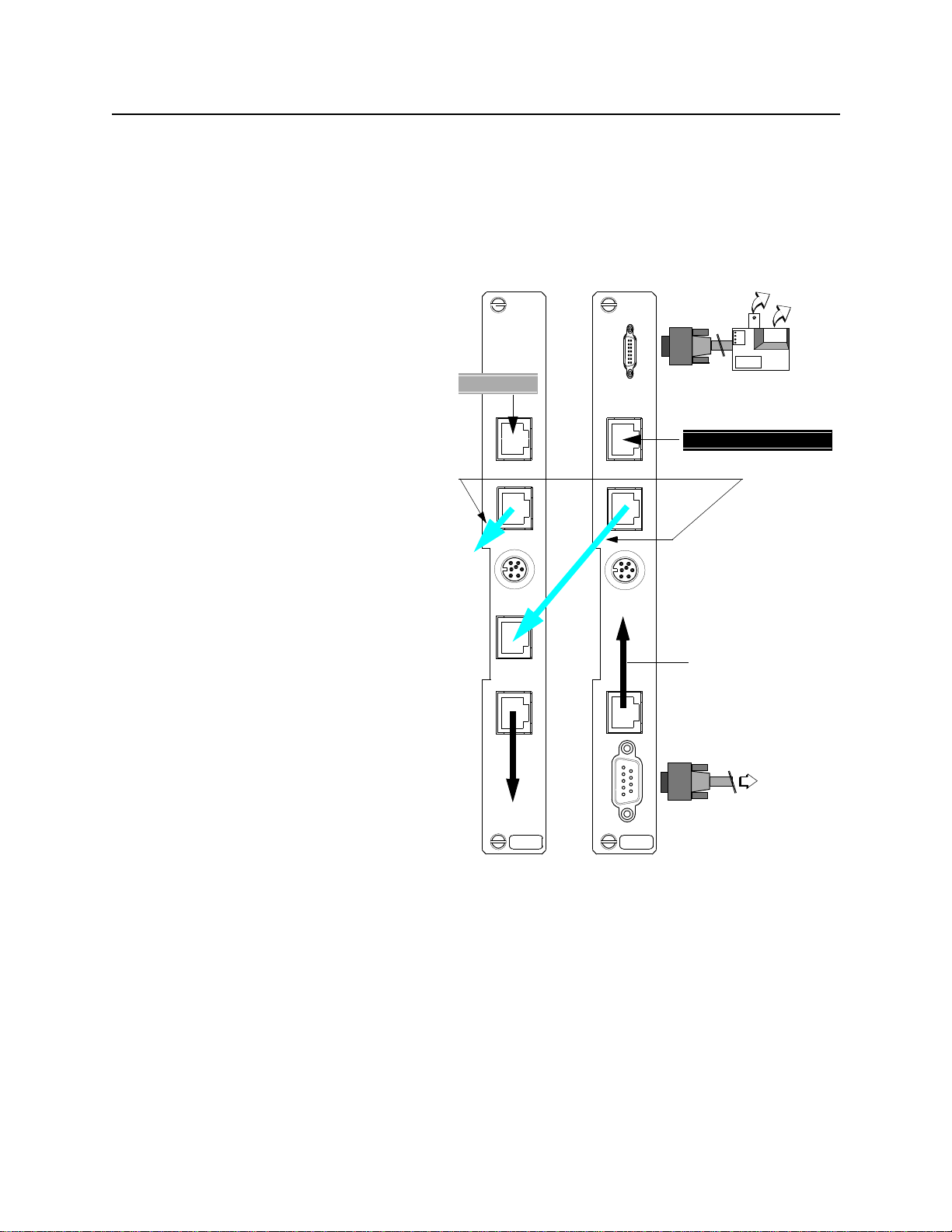
Figure 2-2 Rear view of CIM interconnections
CIM
2010
APS
CIM
2022
APS
To
Ethernet
Installing the Protection Line (Slot 1):
1.
Plug the T1 protection line (P1) into the
Network Port of the CIM 2022 APS in Slot
1.
2.
Run an RJ-48 cable from the
EQPT
Port of
the CIM 2022 APS to its APS IN port.
3.
Connect the APS CIMs in your shelf by
cabling the APS OUT port on the Slot 1
CIM to the APS IN port on the next APS
CIM. Continue daisy-chaining APS OUT
ports to APS IN ports for all the TACs on
your shelf. Leave the APS OUT port on the
lowest priority CIM empty.
NOTE: Both ends of the T1 protection group
must have the same priority cabling
sequence.
Making the network management connections
Use
1.
Management Port (IN)
for SLIP con-
nection.
Use the
2.
Management Extension
port for
Ethernet connection.
3.
Use the Craft interface to configure IP
addresses.
T1 Line (L2)
REV *
APS OUT
APS IN
EQPT EXT TIMING NETWORK
REV *
T1 Protection Line (P1)
NETWORK
APS OUT
To Low Priority CPE
EQPT ETHERNETEXT TIMING
SLIP connection
SLIP
9-pin
connector
Ethernet adapter
(10BaseT and 10Base2
connections)
APS priority
cables
part numbe
458-502572-001
To
SLIP peer
2
-4 Verilink APS 2000 User Manual
Slot 1Slot 2
Page 29

Chapter
3
Configuration
You can configure the node using either SNMP or the Craft
interface. You can access the Craft interface by telnettin g over a
SLIP or Ethernet interface. You can also access the Craft interface
locally by direct connection to a terminal or a PC running a
terminal program.
Configuring the system
Configure the SCC 2120 using the Craft interface. This interface
presents identical menus via direct connection or a Telnet session.
Important notes
When you first install the card, you must configure certain IP
address and related param e ters via the Craft port on the SCC 2120
front panel. These steps are listed in the section "Logging on"
below.
Logging on
Once you configure the IP address, you can access the Craft
interface to make subsequent configuration changes, using either a
direct connection or a Telnet session.
1. Ensure that your entries are spelled correctly and that the
options you choose are consistent with the application you are
setting up.
2. The screens do not refresh automatically after you enter a
command. To view the revised screen, you must press
refresh. Once you enter a command, the word
appears at the end of the prompt time to remind you to
refresh the screen for updated feedback.
To access the APS 2000 node from the
follows:
1. Configure your terminal or terminal program f or:
a. A data rate of 19.2 Kbit/s
b. N o parity
c. One stop bit
RAFT
port, proceed as
C
(UPDATE)
NTER
E
to
d. No flow control (both hardware flow control and X-on/X-off
flow control must be disabled)
Verilink APS 2000 User Manual
3
-1
Page 30

Configuration
RAFT
2. Connect the terminal or PC to the port labe l le d
C
on the
front of the SCC 2120 module. Use one of the two types of
Craft cable:
a. P/N 458-102119-008, DB-9 t o RJ-11—used with notebook or
other computers which present a DB-9 COM port.
b. P/N 458-501788-001, DB- 25 to RJ-11—used with terminals
or computers which present a DB- 25 R S-232 connector.
3. Press the
NTER
key. The prompt
E
4. Log on to the Craft interface by typing "craft" at the
prompt and pressing
NTER
E
to get the
prompt.
If you’re accessing the node for the first time, press
Initially there is no password.
5. If you have set a password, then type the correct password (up
to 6 characters, including spaces). The screen will display
placeholders (
Main Menu
The
Table 3-1 SCC 2120 Main Menu
-- VERILINK SCC NODE CONTROLLER at[1,1]: FW Rev 3.05, May 26, 1999. --
-- VERILINK SCC NODE CONTROLLER at[1,1]: FW Rev 3.05, May 26, 1999. --
-- VERILINK SCC NODE CONTROLLER at[1,1]: FW Rev 3.05, May 26, 1999. -- -- VERILINK SCC NODE CONTROLLER at[1,1]: FW Rev 3.05, May 26, 1999. -FLASH BANK: A Serial Number: 00520710
FLASH BANK: A Serial Number: 00520710
FLASH BANK: A Serial Number: 00520710FLASH BANK: A Serial Number: 00520710
Ethernet Address: A0:6A:00:07:F2:06:
Ethernet Address: A0:6A:00:07:F2:06:
Ethernet Address: A0:6A:00:07:F2:06:Ethernet Address: A0:6A:00:07:F2:06:
Slip Local IP Address: 0.0.0.0, Subnet Mask: 0.0.0.0
Slip Local IP Address: 0.0.0.0, Subnet Mask: 0.0.0.0
Slip Local IP Address: 0.0.0.0, Subnet Mask: 0.0.0.0Slip Local IP Address: 0.0.0.0, Subnet Mask: 0.0.0.0
Ethernet Local IP Address: 192.94.45.242, Subnet Mask: 255.255.255.0
Ethernet Local IP Address: 192.94.45.242, Subnet Mask: 255.255.255.0
Ethernet Local IP Address: 192.94.45.242, Subnet Mask: 255.255.255.0Ethernet Local IP Address: 192.94.45.242, Subnet Mask: 255.255.255.0
SITE NAME: SCC NODE ID: 372
SITE NAME: SCC NODE ID: 372
SITE NAME: SCC NODE ID: 372SITE NAME: SCC NODE ID: 372
<- SLOT ->
<- SLOT ->
<- SLOT -> <- SLOT ->
SHELF 1 2 3 4 5 6 7 8 9 10 11 12 13
SHELF 1 2 3 4 5 6 7 8 9 10 11 12 13
SHELF 1 2 3 4 5 6 7 8 9 10 11 12 13 SHELF 1 2 3 4 5 6 7 8 9 10 11 12 13
1 DL [A] A
1 DL [A] A
1 DL [A] A 1 DL [A] A
2
2
2 2
3
3
3 3
4
4
4 4
KEY: C = CSU, D = DIU, F = DIU/DDS, R = SRD, I = IDCSU, T = TU, A = APS,
KEY: C = CSU, D = DIU, F = DIU/DDS, R = SRD, I = IDCSU, T = TU, A = APS,
KEY: C = CSU, D = DIU, F = DIU/DDS, R = SRD, I = IDCSU, T = TU, A = APS, KEY: C = CSU, D = DIU, F = DIU/DDS, R = SRD, I = IDCSU, T = TU, A = APS,
B = DIU/DBU, S = SMDS, L = HLM
B = DIU/DBU, S = SMDS, L = HLM
B = DIU/DBU, S = SMDS, L = HLM B = DIU/DBU, S = SMDS, L = HLM
will appear.
******
) as you type the password. Press
pSH+>
is displayed.
YOUR PASSWORD?
pSH+>
NTER
E
E
NTER
.
.
S) shelf/slot D) diagnostics
S) shelf/slot D) diagnostics
S) shelf/slot D) diagnosticsS) shelf/slot D) diagnostics
N) near element O) node administration
N) near element O) node administration
N) near element O) node administrationN) near element O) node administration
F) far element M) monitor alarms (OFF)
F) far element M) monitor alarms (OFF)
F) far element M) monitor alarms (OFF)F) far element M) monitor alarms (OFF)
C) configuration A) view alarm buffer
C) configuration A) view alarm buffer
C) configuration A) view alarm bufferC) configuration A) view alarm buffer
P) performance X) log off
P) performance X) log off
P) performance X) log offP) performance X) log off
[1,1] NEAR TAC 2110 >
[1,1] NEAR TAC 2110 >
[1,1] NEAR TAC 2110 >[1,1] NEAR TAC 2110 >
3
-2 Verilink APS 2000 User Manual
Page 31

Table 3-2 SCC 2120 Main Menu Commands
Menu Option Description Instructions
Configuration
S) shelf/slot Used to navigate from module
N) near element Selects the local node. Used to return from a far element session.
F) far element Selects the node at the remote
C) configuration Selects the
P) performance Selects the
D) diagnostics Selects the
O) node
administration
M) monitor alarms
(OFF)
A) view alarm buffer Displays alarm buffer. A history of recent alarms is displayed.
X) log off Exits the
to module within a node.
end of the T1 circuit connected
to the current module, functions
only if ESF FDL has continuity.
Configuration
Menu
.
Performance Menu
Diagnostics Menu
Selects the
Administration Menu
Toggles on/off the monitor
alarms function.
Node
Main Menu
.
. Returns to
Enter the shelf number and slot number of the
desired module, use a comma delimiter (1,2).
With version 3.02 or higher SCC firmware, you
can navigate from module to module in the
remote node, earlier firmware versions only
allowed access to the remote CSU module. The
password required for this access is "800far".
See Figure 3-7 and Table 3-5 below.
.See Chapter 4 of this manual.
.See Chapter 5 of this manual.
See Figure 3-1 and Table 3-3 below.
If monitor alarms is ON, alarm messages are
displayed on the Craft interface as they occur.
No alarm messages are displayed if monitor
alarms is OFF.
pSH+>
pSH+>
pSH+>pSH+>
prompt, the TCP/IP shell.
Node Administration
In addition to the T1 CSU and Automatic Protection Switch
functions, the SCC 2120 i s also an SNMP nod e con troll er. T he
Administration Menu
configure site, Ethernet and SLIP address information.
Some functions on the
firmware upgrade procedures.
Node Administration Menu
The
SCC 2120
Most of the commands on the
documented in Table 3-3 below.
Some of the menu options on the
produce submenus with detailed selections, for instance the
Modem Configuration Menu
, and submenus beneath it, are used to
Node Administration Menu
Node Administration Menu
Main Menu
. Figure 3-1 shows the options presented.
Node Administration Menu
is detailed in Table 3-4.
Node
support
is accessed by selecting O on the
are
Node Administration Menu
will
Verilink APS 2000 User Manual
3
-3
Page 32

Configuration
Figure 3-1 Node Administration Menu
--- NODE CONTROLLER MENU ---
--- NODE CONTROLLER MENU ---
--- NODE CONTROLLER MENU --- --- NODE CONTROLLER MENU ---
T) time
T) time
T) time T) time
D) date
D) date
D) date D) date
I) node id
I) node id
I) node id I) node id
N) site name
N) site name
N) site name N) site name
A) Slip Configuration
A) Slip Configuration
A) Slip Configuration A) Slip Configuration
E) Ethernet Configuration
E) Ethernet Configuration
E) Ethernet Configuration E) Ethernet Configuration
M) Modem Configuration
M) Modem Configuration
M) Modem Configuration M) Modem Configuration
O) IP Gateway
O) IP Gateway
O) IP Gateway O) IP Gateway
H) trap host ip address
H) trap host ip address
H) trap host ip address H) trap host ip address
C) community string (read)
C) community string (read)
C) community string (read) C) community string (read)
W) community string (write)
W) community string (write)
W) community string (write) W) community string (write)
F) flash download
F) flash download
F) flash download F) flash download
B) boot
B) boot
B) boot B) boot
R) reset com ports
R) reset com ports
R) reset com ports R) reset com ports
S) node controller status
S) node controller status
S) node controller status S) node controller status
P) set privileged password
P) set privileged password
P) set privileged password P) set privileged password
U) set unprivileged password
U) set unprivileged password
U) set unprivileged password U) set unprivileged password
Y) element download
Y) element download
Y) element download Y) element download
X) exit menu
X) exit menu
X) exit menu X) exit menu
[1,1] NEAR TAC 2110 >
[1,1] NEAR TAC 2110 >
[1,1] NEAR TAC 2110 >[1,1] NEAR TAC 2110 >
If any changes are made to the Ethernet or SLIP configurations,
those changes do not take effect until the module is rebooted.
Rebooting an SCC 2120 by using the boot command has no effect
on user data passing through the SCC 2120 module.
NOTE:
The SLIP IP address and the Ethernet IP address
must
different network segments in terms of the subnet masks in
use. If the SLIP and Eth ernet addresses are set to reflect the
same network segment an error message “Sendto: new socket
failed” will repeat constantly until the error is corrected and
the SCC 2120 is rebooted.
Table 3-3 Node Administration Commands
Menu Option Description Instructions
T) time Sets the time of
day.
D) date Sets the date. Enter new date (mm-dd-yy): — use format shown.
I) node id Sets a numeric
identifier.
Enter new time (hh:mm:ss): — use the format shown.
Maximum field length = ten digits, distinguishes one node
from another, each node in a network must have a unique
node id.
reflect
3
-4 Verilink APS 2000 User Manual
Page 33

Menu Option Description Instructions
Site Name: Tech Pubs SCC 2120 Change (Y/N)?
N) site name Sets an alpha-
numeric identifier
used to tell one
node from another.
A) Slip Configuration Calls a submenu
which is used to
configure the RS-
232 electrical, DB-9
physical, Serial Line
Internet Protocol
port on the rear
connector module.
Site Name: Tech Pubs SCC 2120 Change (Y/N)?
Site Name: Tech Pubs SCC 2120 Change (Y/N)?Site Name: Tech Pubs SCC 2120 Change (Y/N)?
selected, a second prompt appears:
New Site Name (40)
New Site Name (40)
New Site Name (40)New Site Name (40)
alpha-nume ri c characters.
---- host configuration for sli p ----
---- host configuration for sli p ----
---- host configuration for sli p ---- ---- host configuration for sli p ----
L) Slip Local ip address : 192.94.46.222
L) Slip Local ip address : 192.94.46.222
L) Slip Local ip address : 192.94.46.222 L) Slip Local ip address : 192.94.46.222
P) Slip Peer ip address : 192.94. 46.101
P) Slip Peer ip address : 192.94. 46.101
P) Slip Peer ip address : 192.94. 46.101 P) Slip Peer ip address : 192.94.46.101
S) Slip Subnet Mask : 255.255.255.0
S) Slip Subnet Mask : 255.255.255.0
S) Slip Subnet Mask : 255.255.255.0 S) Slip Subnet Mask : 255.255.255.0
X) exit
X) exit
X) exit X) exit
: — enter a site name using up to 40
Configuration
— if yes is
E) Ethernet
Configuration
M) Modem
Configuration
SLIP may be used in
lieu of or along with
the Ethernet
connectivity
described below.
If SLIP will not be
used, leave the SLIP
Local IP address set
to 0.0.0.0.
Calls a short
submenu which is
used to configure
the AAUI-14
Ethernet connector
on the rear
connector module.
An Ethernet
transceiver which
supports both
10BaseT and
10Base2 is pro vided
with each SCC
2120.
Calls the Modem
Configuration
Menu.
— the SLIP Local I P ad d ress is for this SCC 2120.
— the SLIP Peer address must be set for the trap host IP
address in curr ent SCC firmware .
— the SLIP Subnet mask shown is for a TCP/IP class C
address, use the normal subnet mask conventions.
---- host configur ation for Ethernet ----
---- host configur ation for Ethernet ----
---- host configur ation for Ethernet -------- host configur ation for Ethernet ----
L) Ethernet Local ip address : 192.94.45.242
L) Ethernet Local ip address : 192.94.45.242
L) Ethernet Local ip address : 192.94.45.242 L) Ethernet Local ip address : 192.94.45.242
S) Ethernet Subnet Mask : 255.255.255.0
S) Ethernet Subnet Mask : 255.255.255.0
S) Ethernet Subnet Mask : 255.255.255.0 S) Ethernet Subnet Mask : 255.255.255. 0
T) Ethernet Type : Ethernet/DIX
T) Ethernet Type : Ethernet/DIX
T) Ethernet Type : Ethernet/DIX T) Ethernet Type : Ethernet/DIX
X) exit
X) exit
X) exit X) exit
— the Ethernet local IP address is for this SCC 2120.
— the Ethernet subnet mask shown is for a TCP/IP class C
address, use normal subnet mask conve nti ons.
— the Ethernet type must be set to Ethernet/DIX.
Required only if SLIP will be used over a dial-up modem
connection, see the table below.
O) IP Gateway Sets the address for
a device, usually a
router, used to
reach IP addresses
on a different
network segment.
Verilink APS 2000 User Manual
---- Internet Gateway Configuration ----
---- Internet Gateway Configuration ----
---- Internet Gateway Configuration ---- ---- Internet Gateway Configuration ----
G) Internet Gateway IP address : 128.0.0.0
G) Internet Gateway IP address : 128.0.0.0
G) Internet Gateway IP address : 128.0.0.0 G) Internet Gateway IP address : 128.0.0.0
— if no IP gateway is used, leave the default value as
shown, if a gateway device is used, type “G” and enter the
IP address of the gateway.
3
-5
Page 34

Configuration
Menu Option Description Instructions
H) trap host ip
address
C) community string
(read)
W) community string
(write)
F) flash download Used to upgrade
B) boot Reboots (resets) the
Used to configure IP
addresses fo r up to
four SNMP
managers to which
alarm information
(trap messages) will
be sent.
Set number of trap
hosts equal to the
number of IP
addresse s us e d .
SNMP community
string, a
rudimentary
password.
SNMP community
string, a
rudimentary
password.
SCC firmware.
SCC 2120.
---- host configuration for traps ----
---- host configuration for traps ----
---- host configuration for traps ---- ---- host configuration for traps ----
N) Number of trap hosts : 1
N) Number of trap hosts : 1
N) Number of trap hosts : 1 N) Number of trap hosts : 1
1) host 1 ip address : 192.94.45.111
1) host 1 ip address : 192.94.45.111
1) host 1 ip address : 192.94.45.111 1) host 1 ip address : 192.94.45.11 1
2) host 2 ip address : 0.0.0.0
2) host 2 ip address : 0.0.0.0
2) host 2 ip address : 0.0.0.0 2) host 2 ip address : 0.0.0.0
3) host 3 ip address : 0.0.0.0
3) host 3 ip address : 0.0.0.0
3) host 3 ip address : 0.0.0.0 3) host 3 ip address : 0.0.0.0
4) host 4 ip address : 0.0.0.0
4) host 4 ip address : 0.0.0.0
4) host 4 ip address : 0.0.0.0 4) host 4 ip address : 0.0.0.0
X) exit
X) exit
X) exit X) exit
Community string (Read): public Change (Y/N)?
Community string (Read): public Change (Y/N)?
Community string (Read): public Change (Y/N)?Community string (Read): public Change (Y/N)?
Community string (64):
Community string (64):
Community string (64):Community string (64):
The current value for the read communi ty strin g is “pub lic”
and a string of up to 64 characters can be entered.
Community string (Write): Right Change (Y/N)?
Community string (Write): Right Change (Y/N)?
Community string (Write): Right Change (Y/N)?Community string (Write): Right Change (Y/N)?
Community string (64)
Community string (64)
Community string (64)Community string (64)
The current value for the write community string is “right”
and a string of up to 64 characters can be entered.
See the section “Configuration procedure” in this chapte r.
Current Bank: 'B'; flash bank to boot from (A or B)
Current Bank: 'B'; flash bank to boot from (A or B)
Current Bank: 'B'; flash bank to boot from (A or B)Current Bank: 'B'; flash bank to boot from (A or B)
required when any IP address / Ethernet configurations
have been changed, rebooting does not impact user data.
:
—
R) reset com ports Resets the hardwa re
used for Craft port
and SLIP port
connections.
S) node controller
status
P) set privileged
password
U) set unprivileged
password
Y) element download Us ed for upgrading
X) exit menu Exits this menu. Returns to SCC 2120
Modem Configuration
Not applicable. Produces error message:
Sets password for
the privileged level
operator.
Sets password for
the unprivileged
level operator.
modules other than
the SCC 2120.
When M is selected on the SCC 2120
Modem Configuration Menu
the
No confirmation is required or given, the command prompt
returns immediately.
Used if a port seems to be in a locked condition.
Current Privileged Pass word : <> Chan ge (Y /N) ?
Current Privileged Pass word : <> Chan ge (Y /N) ?
Current Privileged Pass word : <> Chan ge (Y /N) ?Current Privileged Pass word : <> Chan ge (Y /N) ?
Privileged users may make configuration changes.
Current Unprivileged Pa s sw o rd : <> Chan ge (Y /N ) ?
Current Unprivileged Pa s sw o rd : <> Chan ge (Y /N ) ?
Current Unprivileged Pa s sw o rd : <> Chan ge (Y /N ) ?Current Unprivileged Pa s sw o rd : <> Chan ge (Y /N ) ?
Unprivileged users have read-o nly access, they may not
make configur at i o n ch an ges .
See the section “Element Download” in this chapter.
Not Implemented in this release
Not Implemented in this release
Not Implemented in this releaseNot Implemented in this release
Main Menu
.
Node Administration Menu
appears.
.
,
3
-6 Verilink APS 2000 User Manual
Page 35

Figure 3-2 Modem Configuration Menu
---- Modem Configuration ----
---- Modem Configuration ----
---- Modem Configuration ---- ---- Modem Configuration ----
Modem Status: NOT CONNECTED
Modem Status: NOT CONNECTED
Modem Status: NOT CONNECTED Modem Status: NOT CONNECTED
D) Answer : DISABLED
D) Answer : DISABLED
D) Answer : DISABLED D) Answer : DISABLED
C) Answer Command : AT &C1&D2&Q0 S0=1
C) Answer Command : AT &C1&D2&Q0 S0=1
C) Answer Command : AT &C1&D2&Q0 S0=1 C) Answer Command : AT &C1&D2&Q0 S0=1
T) Answer Inactive Timeout : 0 seconds
T) Answer Inactive Timeout : 0 seconds
T) Answer Inactive Timeout : 0 seconds T) Answer Inactive Timeout : 0 seconds
B) Dial-Out : DISABLED
B) Dial-Out : DISABLED
B) Dial-Out : DISABLED B) Dial-Out : DISABLED
U) Dial-Out Command : AT &C1&D2&K3&Q0 X4 S0=0 DT
U) Dial-Out Command : AT &C1&D2&K3&Q0 X4 S0=0 DT
U) Dial-Out Command : AT &C1&D2&K3&Q0 X4 S0=0 DT U) Dial-Out Command : AT &C1&D2&K3&Q0 X4 S0=0 DT
N) Dial-Out Number :
N) Dial-Out Number :
N) Dial-Out Number : N) Dial-Out Number :
R) Dial-Out connect retries : 0
R) Dial-Out connect retries : 0
R) Dial-Out connect retries : 0 R) Dial-Out connect retries : 0
K) Dial-Out connect timeout : 60 seconds
K) Dial-Out connect timeout : 60 seconds
K) Dial-Out connect timeout : 60 seconds K) Dial-Out connect timeout : 60 seconds
I) Dial-Out Inactive timeout : 0 seconds
I) Dial-Out Inactive timeout : 0 seconds
I) Dial-Out Inactive timeout : 0 seconds I) Dial-Out Inactive timeout : 0 seconds
S) Dial-Out W) Set default commands
S) Dial-Out W) Set default commands
S) Dial-Out W) Set default commands S) Dial-Out W) Set default commands
A) Answer H) Hangup
A) Answer H) Hangup
A) Answer H) Hangup A) Answer H) Hangup
X) exit
X) exit
X) exit X) exit
Configuration
[1,1] NEAR TAC 2110 >
[1,1] NEAR TAC 2110 >
[1,1] NEAR TAC 2110 >[1,1] NEAR TAC 2110 >
Modem
Configuration
Options
Modem Configuration Menu
The
is used to support an optional
dial-up modem which may be connected to the port labelled
Management Port In on the rear connector module. This port
supports the Serial Line Interface Protocol, a subset of TCP/IP
designed to support Internet protocols across a low-speed RS-232
Wide Area Network connection.
The Modem Status field on the
Modem Configuration Menu
reflects the status of the Data Carrier Detect lead (DCD) on th e
Management Port In.
If SLIP is used, it may be used with or without a modem. To use SLIP
without a modem, be certain that the Answer and Dial-Out fields
are set to DISABLED.
The options on the
Modem Configuration Menu
are documented
in Table 3-4 below.
Verilink APS 2000 User Manual
3
-7
Page 36

Configuration
Table 3-4 Modem Configuration Commands
Menu Option Description Instructions
D) Answer Toggles answer mode
C) Answer Command Command string to be
T) Answer Inactive
Timeout
B) Dial-Out Toggles on/off dialing a
U) Dial-Out
Command
N) Dial-Out Number Phone number to call. Enter a phone number if using dial-out.
R) Dial-Out connect
retries
K) Dial-Out connect
timeout
on/off.
sent to modem to setup
auto-answer mode.
Length of time an
incoming call is allowed to
be idle before the modem
is disconnected.
stored number to report
alarms to a trap host.
Command sent to modem
to initiate a call.
Number of times to retry
dialing out to trap host.
Length of time to wait for
a connection after
initiating a di al-out call.
Select ENABLE to support answering incoming calls.
Select DISABLE to inhibit answering calls.
The default auto-answer string is shown in Figure 3-2,
use this string or modify it per the requirements of
your modem.
Enter a value, in seconds, for idle time before
disconnect (range = 1 to 255), if this value is reached,
the DTR lead is toggled low to disconnect the modem
(modem should be set for [&D2] disconnect on DTR
low).
Select ENABLE to support dialing out to a trap host
when alarm conditions occur or clear or DISABLE if the
SCC 2120 is never to dial out to a trap host.
The default dia l- o ut s tring is shown in Figure 3-2, use
this string or modify it per the requirements of your
modem and phone line.
Enter a number in the range of 1-255, or zero to
disable the retry function.
Enter a value, in seconds, to wait for a connection
after dialing a call to a trap host, range = 10 to 255
seconds.
I) Dial-Out Inactive
timeout
S) Dial-Out Command used for
W) Set default
commands
A) Answer Sends answer string. Use this command to set modem to answer mode by
H) Hangup Disconnects modem. Causes modem to disconnect now by dropping DTR.
X) exit Exits to menu above. Returns to
Configuration
Length of time a dial-out
call is allowed to be idle
before the modem is
disconnected.
testing.
Rests all modem menu
items to default values.
Enter a value, in seconds, for idle time before
disconnect (range = 1 to 255), if this value is reached,
the DTR lead is toggled low to disconnect the modem
(modem should be set for [&D2] disconnect on DTR
low).
The Dial-Out command causes the modem to dial
now.
Use this command to set all options on this menu to
their original, factory default values, disables modem.
sending the config ured answer command now .
Node Administration Menu
Follow these steps to configure your CSU modules.
.
procedure
1. Select the SCC 2120 in Shelf 1, Slot 1, by entering S and
following the format shown at the prompt line.
2. Enter "N" to specify the near end element. The prompt lin e will
display
identify the module’s location.
[1,1] NEAR TAC 2110
. The numbers in the brackets
3
-8 Verilink APS 2000 User Manual
Page 37

Configuration
This prompt line is standard whenever you are configuring an
SCC or TAC.
3. Enter "O" to access the Node Administration screen.
Figure 3-3 Node Controller Menu
--- NODE CONTROLLER MENU ---
--- NODE CONTROLLER MENU ---
--- NODE CONTROLLER MENU --- --- NODE CONTROLLER MENU -- T) time
T) time
T) time T) time
D) date
D) date
D) date D) date
I) node id
I) node id
I) node id I) node id
N) site name
N) site name
N) site name N) site name
A) Slip Configuration
A) Slip Configuration
A) Slip Configuration A) Slip Configuration
E) Ethernet Configuration
E) Ethernet Configuration
E) Ethernet Configuration E) Ethernet Configuration
M) Modem Configuration
M) Modem Configuration
M) Modem Configuration M) Modem Configuration
O) IP Gateway
O) IP Gateway
O) IP Gateway O) IP Gateway
H) trap host ip address
H) trap host ip address
H) trap host ip address H) trap host ip address
C) community string (read)
C) community string (read)
C) community string (read) C) community string (read)
W) community string (write)
W) community string (write)
W) community string (write) W) community string (write)
F) flash download
F) flash download
F) flash download F) flash download
B) boot
B) boot
B) boot B) boot
R) reset com ports
R) reset com ports
R) reset com ports R) reset com ports
S) node controller status
S) node controller status
S) node controller status S) node controller status
P) set privileged password
P) set privileged password
P) set privileged password P) set privileged password
U) set unprivileged password
U) set unprivileged password
U) set unprivileged password U) set unprivileged password
Y) element download
Y) element download
Y) element download Y) element download
X) exit menu
X) exit menu
X) exit menu X) exit menu
SNMP Parameters
[1,1] NEAR TAC 2110 >
[1,1] NEAR TAC 2110 >
[1,1] NEAR TAC 2110 >[1,1] NEAR TAC 2110 >
Before proceeding, check with your System Administrator for
the exact values you will need to use for all the following
parameters. These parameters are specific to the local LAN
segment, SLIP peer address (if SLIP is used), SCC module and
SNMP management.
Trap Host IP address.
Address chosen by the user to receive
AS2000 alarms. The SNMP network manager will receive all
traps.
Community string.
An administratively assigned string
identifying the relationship between SNMP entities.
Community string (read).
The string used to perform SNMP gets.
The default value in the SCC is "public". Change the SCC’s
string to match the SNMP network manager’s read community
string for this node.
Community string (write).
The string used to perform SNMP sets.
The default value in the SCC is "netman". Change the SCC’s
string to match the SN MP network m anager’s write commu nity
string for this node.
Verilink APS 2000 User Manual
3
-9
Page 38

Configuration
4. Configure the specific parameters for SLIP and/or Ethernet.
To configure for SLIP
a.
, enter "A" to access the following
configuration screen.
Figure 3-4
---- host configuration for slip ----
---- host configuration for slip ----
---- host configuration for slip ---- ---- host configuration for slip ----
L) Slip Local ip address : 192.94.45.96
L) Slip Local ip address : 192.94.45.96
L) Slip Local ip address : 192.94.45.96 L) Slip Local ip address : 192.94.45.96
P) Slip Peer ip address : 192.94.45.101
P) Slip Peer ip address : 192.94.45.101
P) Slip Peer ip address : 192.94.45.101 P) Slip Peer ip address : 192.94.45.101
S) Slip Subnet Mask : 255.255.255.0
S) Slip Subnet Mask : 255.255.255.0
S) Slip Subnet Mask : 255.255.255.0 S) Slip Subnet Mask : 255.255.255.0
X) exit
X) exit
X) exit X) exit
[1,1] NEAR TAC
[1,1] NEAR TAC
[1,1] NEAR TAC [1,1] NEAR TAC
2110 >
2110 >
2110 >2110 >
Sequentially enter and configure each parameter on the
screen.
To configure for Ethern et
b.
configuration screen.
Figure 3-5 Ethernet Configuration
---- host configuration for Ethernet ----
---- host configuration for Ethernet ----
---- host configuration for Ethernet ---- ---- host configuration for Ethernet ----
L) Ethernet Local ip address : 192.94.45.96
L) Ethernet Local ip address : 192.94.45.96
L) Ethernet Local ip address : 192.94.45.96 L) Ethernet Local ip address : 192.94.45.96
S) Ethernet Subnet Mask : 255.255.255.0
S) Ethernet Subnet Mask : 255.255.255.0
S) Ethernet Subnet Mask : 255.255.255.0 S) Ethernet Subnet Mask : 255.255.255.0
T) Ethernet Type : Ethernet/DIX
T) Ethernet Type : Ethernet/DIX
T) Ethernet Type : Ethernet/DIX T) Ethernet Type : Ethernet/DIX
X) exit
X) exit
X) exit X) exit
[1,1] NEAR TAC 2110 >
[1,1] NEAR TAC 2110 >
[1,1] NEAR TAC 2110 > [1,1] NEAR TAC 2110 >
Sequentially enter and configure each parameter on the
screen.
To configure traps,
c.
enter "
configuration screen.
, enter "E" to access the following
M"
to access the following
3
-10 Verilink APS 2000 User Manual
Page 39

Figure 3-6 SNMP Trap Configuration
---- host configuration for traps ----
---- host configuration for traps ----
---- host configuration for traps ---- ---- host configuration for traps ----
N) Number of trap hosts : 1
N) Number of trap hosts : 1
N) Number of trap hosts : 1N) Number of trap hosts : 1
1) host 1 ip address : 192.94.45.77
1) host 1 ip address : 192.94.45.77
1) host 1 ip address : 192.94.45.771) host 1 ip address : 192.94.45.77
1) host 2 ip address : 0.0.0.0
1) host 2 ip address : 0.0.0.0
1) host 2 ip address : 0.0.0.01) host 2 ip address : 0.0.0.0
1) host 3 ip address : 0.0.0.0
1) host 3 ip address : 0.0.0.0
1) host 3 ip address : 0.0.0.01) host 3 ip address : 0.0.0.0
1) host 4 ip address : 0.0.0.0
1) host 4 ip address : 0.0.0.0
1) host 4 ip address : 0.0.0.01) host 4 ip address : 0.0.0.0
X) exit
X) exit
X) exitX) exit
Sequentially enter and configure each parameter on the
screen. (The range for
Number of trap hosts
4.)
Configuration
is from 1 to
d. To return to the
Node Administration Menu
, type "X".
Verilink APS 2000 User Manual
3
-11
Page 40

Configuration
Configuration Menu
Access the
Menu
Figure 3-7 APS Configuration Menu
APS CONFIGURATION -- FW Rev 4.0 HW Fab 0.8 Type TAC 2110 --
APS CONFIGURATION -- FW Rev 4.0 HW Fab 0.8 Type TAC 2110 --
APS CONFIGURATION -- FW Rev 4.0 HW Fab 0.8 Type TAC 2110 -- APS CONFIGURATION -- FW Rev 4.0 HW Fab 0.8 Type TAC 2110 --
|-----------------------|
|-----------------------|
|-----------------------| |-----------------------|
-------<< eq <<-------| K) aps control AUTO |-------<< net <<-------
-------<< eq <<-------| K) aps control AUTO |-------<< net <<-------
-------<< eq <<-------| K) aps control AUTO |-------<< net <<--------------<< eq <<-------| K) aps control AUTO |-------<< net <<------ W) framing SF | | W) framing ESF
W) framing SF | | W) framing ESF
W) framing SF | | W) framing ESF W) framing SF | | W) framing ESF
F) format AMI | | F) format B8ZS
F) format AMI | | F) format B8ZS
F) format AMI | | F) format B8ZS F) format AMI | | F) format B8ZS
J) jitt buf 40 BITS | | J) jitt buf 40 BITS
J) jitt buf 40 BITS | | J) jitt buf 40 BITS
J) jitt buf 40 BITS | | J) jitt buf 40 BITS J) jitt buf 40 BITS | | J) jitt buf 40 BITS
R) eq crc REGEN | | R) net crc REGEN
R) eq crc REGEN | | R) net crc REGEN
R) eq crc REGEN | | R) net crc REGEN R) eq crc REGEN | | R) net crc REGEN
Y) xcode yel OFF | | Y) xcode yel OFF
Y) xcode yel OFF | | Y) xcode yel OFF
Y) xcode yel OFF | | Y) xcode yel OFF Y) xcode yel OFF | | Y) xcode yel OFF
M) distance 0-133 | | L) lbO 0 DB
M) distance 0-133 | | L) lbO 0 DB
M) distance 0-133 | | L) lbO 0 DB M) distance 0-133 | | L) lbO 0 DB
|-----------------------| Z) density 12%+80z
|-----------------------| Z) density 12%+80z
|-----------------------| Z) density 12%+80z |-----------------------| Z) density 12%+80z
X) exit menu C1-C5) canned config
X) exit menu C1-C5) canned config
X) exit menu C1-C5) canned config X) exit menu C1-C5) canned config
A) loop code/test ptns FULL T1 Code/PTN B) diu clock THRU
A) loop code/test ptns FULL T1 Code/PTN B) diu clock THRU
A) loop code/test ptns FULL T1 Code/PTN B) diu clock THRU A) loop code/test ptns FULL T1 Code/PTN B) diu clock THRU
P) prm OFF
P) prm OFF
P) prm OFF P) prm OFF
D) select D&I DS0s (1,-,24)
D) select D&I DS0s (1,-,24)
D) select D&I DS0s (1,-,24) D) select D&I DS0s (1,-,24)
_ _ _ _ _ _ _ _ _ _ _ _
_ _ _ _ _ _ _ _ _ _ _ _
_ _ _ _ _ _ _ _ _ _ _ _ _ _ _ _ _ _ _ _ _ _ _ _
_ _ _ _ _ _ _ _ _ _ _ _
_ _ _ _ _ _ _ _ _ _ _ _
_ _ _ _ _ _ _ _ _ _ _ _ _ _ _ _ _ _ _ _ _ _ _ _
G) Alarm ENABLE
G) Alarm ENABLE
G) Alarm ENABLE G) Alarm ENABLE
[1,1] NEAR TAC 2110 >
[1,1] NEAR TAC 2110 >
[1,1] NEAR TAC 2110 >[1,1] NEAR TAC 2110 >
Configuration Menu
.
by typing "C" at the APS 2000
Main
Configuration Menu Commands
Some of the commands on the CSU
on both the left and right sides of the screen. Commands that are
used for both DSX-1 equipment and T1 network ports are repeated
on both the equipment and the net side of the diagram. Command
prompts for these options present pairs of values: the value for the
equipment side is followed by the value for the network side.
For example, if connecting a D4 (SF) channel bank to an ESF T1
circuit the SF,ESF framing selection would be used.
Table 3-5 below describes all of the SCC 2020 CSU
Menu
options:
3
-12 Verilink APS 2000 User Manual
Configuration Menu
Configuration
are shown
Page 41

Table 3-5 CSU Configuration Options
Menu Option Description Instructions
Configuration
W) framing Selects T1 framing
mode for both DSX-1
equipment port and
T1 network port.
Selection for the
Equipment side must
match the optioning
of the equipment.
Selection for the T1
network side must
match the type of T1
installed by the
network service
provider.
F) format Selects AMI or B8ZS
for the DSX-1
equipment and T1
network line codes,
must match T1 and
equipment settings.
In Mux mode, (where
no DSX-1 equipment
is used) only the
second parameter is
meaningful.
First value = DSX-1 equipment, second value = T1 circuit.
1(SF,SF) — D4 equipment and a D4 T1.
2(ESF,SF) — ESF equipment and a D4 T1.
3(SF,ESF) — D4 equipment and an ESF T1.
4(ESF,ESF) — ESF equipment and an ESF T1.
5(UF,UF) — unframed equ ipm en t on a n unf ra med T1 ( nev er
use this option on a T1 circuit provided by a telephone
company).
6(SF,ZBT) — D4 equipment on a Z ero Bit Time Slot Insertion
T1 (there are no ZBTSI T1 circuits, do not use this option).
7(ESF,ZBT) — ESF equipment on a ZBTSI T1 (there are no
ZBTSI T1 circuits, do not use this option).
First value = DSX-1 equipment, second value = T1 circuit.
1(AMI,AMI) — AMI coded DSX-1 equipment on an AMI T1.
2(AMI,B8ZS) — AMI DSX-1 equipment on a B8ZS T1.
3(B8ZS,AMI) — B8ZS DSX-1 equipment on an AMI T1 (this
selection is problema tic unless the equipme nt is conf igured
to use only 56K of each DS0 instead of 64K per DS0).
4(B8ZS,B8ZS) — B8ZS DSX-1 equipment on a B8ZS T1.
J) jitt buf Jitter Buffer selects
the size of the jitter
buffer, in bits, on the
DSX-1 and Network
sides of the CSU.
Larger buff ers are
more resistant to a
jittery signal, smaller
buffers introduce
less delay.
R) eq crc Selects whether or
not the CSU will
regenerate the CRC-6
error checking used
in ESF framing on
both, one, or no
sides.
Y) xcode yel Selects whether
yellow alarms will be
translated from the
D4 bit 2 method to
the ESF FDL method.
1(16,16) — Sets both buffers to 16 bit depth, less resilience
to jitter and less delay.
2(40,16) — Sets DSX-1 side to 40 bits and network side to
16 bits.
3(16,40) — Sets the DSX-1 side to 16 bits and the network
side to 40 bits.
4(40,40) — Sets the default value of 40-bit jitter buffer on
both sides of the CSU.
1(PASS) — same type framing on both sides.
2(NET TO EQ) — ESF equipment on a non-ESF T1 .
3(EQ TO NET) — non-ESF equipment on an ESF T1.
4(BOTH) — use in Drop and Insert mode if equipment and
T1 are both ESF.
1(OFF) — use for same type framing on both sides or to
have the CSU dr op yellow ala rms with dissim ilar framing.
2(NET TO EQ) — ESF equipment and D4 T1.
3(EQ TO NET) — D4 equipment on an ESF T1.
4(BOTH) — not used.
Verilink APS 2000 User Manual
3
-13
Page 42

Configuration
Menu Option Description Instructions
M) distance Cable length option,
used to increase DSX1 signal strength
when DSX-1 cable is
long.
L) lbO Line build out is used
to reduce the signal
strength being sent
to the T1 network.
New T1 circuits
installed by a
telephone company
in the USA will have a
smart jack, use 0db.
K) aps control Selects the mode for
the Automatic
Protection Switch
function.
T) alm thld Selects enabling or
disabling thresholds.
Z) density Selects density
enforcement
technique.
Density should
always be set to
NONE on a B8ZS T1,
B8ZS allows a full
64K per DS0.
Density should never
be set to NONE on an
AMI T1.
Choices are: (1)0-133 (2)133-266 (3)266-399 (4)399-533
(5)533-655, select the value that most nearly equals the
length of the cable between the CSU and the local DSX-1
equipment.
(1) 0 db — use this value if a smart jack (network
termination device) ha s been inst al led by the tele p hon e
carrier, or if the first active device on the T1 is between
2,000 and 3,000 feet away.
(2) 7.5 db — use this value only if there is no smart jack and
the first repeater is 1,000 to 2,000 feet away.
(3) 15 db — use this value only if there is no smart jack and
the first repeater is zero to 1,000 feet away.
See the secti on ""APS Control Modes"" below.
(1)disable — Alarm threshold function is shut off.
(2)default — Defaul t val ues for alarm thresholds are
enabled.
(1)NONE — no density enf orcemen t, use this value only and
always on a B8ZS T1.
(2)12 — The CSU begins stuffing ones into the user
datastream after 12 consecutive zeroes.
(3)62411— The CSU enforces AT&T public ation 62411
density restrictions (average 12.5% minimum ones density).
(4)80 0's — The CSU begins stuffing ones into the user
datastream after 80 consecutive zeroes (recommended).
(5)15 0's — The CSU begins stuffing ones into the user
datastream after 15 consecutive zeroes.
C1-C5) canned
config
3
-14 Verilink APS 2000 User Manual
Allows selection of
any of five complete
configurations which
vary according to
framing and line
coding on Equipment
and Network sides.
Canned configur ation #1, EQPT=SF/AMI NET=ESF/AMI.
Canned configur ati o n #2 , EQ PT = ES F /AMI NET=ESF /AM I.
Canned configur ati o n #3 , EQ PT = SF /AMI NET=ESF/B8ZS.
Canned configur ati o n #4 , EQ PT = SF/ B 8 Z S NET=ESF/B8 Z S.
Canned configuration #5, EQPT=ESF/B8ZS NET=ESF/B8ZS.
Page 43

Menu Option Description Instructions
Configuration
B) diu clock Selects the source of
the transmit clock
used by the CSU to
transmit data toward
the T1 network.
Note that in the APS
2000 product this
option is ignored, the
SCC 2120 performs
as though THRU
timing were selected.
P) prm Performance
Response Messages
may optionally be
sent in the 4K FDL
portion of an ESF
framed T1.
G) Alarm Determin es wheth er
or not alarm
messages are
presented.
X) exit menu Exit this menu. Returns to t he SCC 2120
(1)THRU — The CSU derives transmit clock from the
transmit datastream of the DSX-1 equipment, automatically
selected in the APS 2000 produ ct.
(2)INT — Does not apply to the APS 2000.
(3)EXT 422 — Does not apply to the APS 2000.
(4)EXT TTL — Does not apply to the APS 2000.
(5)NET — Does not apply to the APS 2000.
(6)EQ — Does not apply to the APS 2000.
(7)TIU — Does not apply to the APS 2000.
(8)DIU — Does not apply to the APS 2000.
1(NO) — Performance response messages received from the
network are ignored, no messa ges are sent. Re quired to use
the FDL portion of ESF framing for Automatic Protection
Switch funcions.
2(USER) — Does not apply to the APS 2000.
0(Disable) — Alarm reporting is turned off.
1(Enable) — Alar m reporting is enabled, messages will
appear on the Craft terminal as alar m s occur and clear.
Main Menu
.
APS Control Modes
Normal/Reset
mode
5. Configure your CSUs according to the information above. Once
you have finished configuring the CSUs, you must initialize
the system.
APS 2000 operates in one of four different control modes to
provide flexibility in both normal switching functions and
maintenance activities. Switching and restoral may be fully
automatic, semi-automatic, or manual, or they may be inhibited
altogether. The four control modes are described in this section.
Normal/Reset mode is the semi-automatic control mode. A T1 line
operating in this mode will switch service to the protection line
automatically when appropriate, but will remain on the protection
line, even after the failure clears, until the user asserts the “Reset”
command. The purpose is to allow trapping of intermittent or brief
T1 line failures, or to correlate a line failure with any other
abnormal system activity.
Normal/Rese t m o de is s et b y de fa ult until anothe r co n tr o l mo d e is
selected. Whenever the APS control status indication displays
NORMAL
, the line must be manually reset (select
RESET
from the
command line) after a switch has occurred and after verifyi ng that
the trouble has been cleared. Asserting
RESET
while the line is still
failed will have no effect.
Verilink APS 2000 User Manual
3
-15
Page 44

Configuration
While a switch is in process (service transferred to the protection
line), the original working line may be tested either locally or
remotely to verify that the trouble still exists or to ascertain the
nature of the trouble. Since traffic is operating on the protection
line during these tests, no service degradation will occur during
testing of the effected T1 line.
The Normal/Reset mode may be affected by failures of higher
priority T1 lines. If the protection line is not available, either
because it is also failed or because a higher priority T1 line has
failed, any lower priority lines will not attempt to transfer and will
reset automatically to the original circuit if al ready transferred.
The Normal/Reset control mode may be selected for both working
and protection lines, bu t is more ap propriat e for worki ng line s. For
example, if a lightning storm in the middle of night, caused the
protection line to fail when no maintenance personnel were
available to reset it, it would remain unavailable to other lines until
reset in the morning.
Manual switch
mode
The Manual Switch control mode forces an otherwi se normal circuit
to switch service to the protection line and remain switched as long
as manual is asserted.
MANUAL
system but may be selected at both ends. The end (or ends) where
MANUAL
constraints of the priority system as discussed above) and sends
the switch code BOP to the fa r end to force it to also switch to the
spare. This manually forced switch will remain in effect, regardless
of errors or lack of errors, until anot her contro l mode is a sserted or
the protection line becomes unavailable due to a failed protection
line or failure of a higher priority working line.
The
accomplished on a working T1 line without disrupting service. It
also may be used to eliminate “ping-ponging” of an intermittent
line. If a line is experiencing intermittent error bursts, it may be
desirable to leave it on the protection line full time. Conversely, if
the error burst s ar e o f very short durati on , i t ma y be de s ir able to
prevent the effected line from switching at all so that any lower
priority lines with more severe problems may have access to the
protection line without being intermittently “bumped.” Use the
INHIBIT
need only be selected at one end (either end) of the
is selected is forced to switch to the spare (within the
MANUAL
mode may be used so that routine testing may be
function, desc ribed next, to preve n t a line from switching.
Inhibit
Inhibit
The
Inhibit mode
3
-16 Verilink APS 2000 User Manual
InhibitInhibit
spare or restores an already switched circuit back onto its working
line.
prevent the possibility of a “half switch.”
INH
may be used to prevent a “priority bump.” For example, if
routine testing is to be performed on the priority #2 line,
asserted on the priority #1 line will prevent it from bumping off the
priority #2 line in the event of a failure on #1.
control mode prevents a line from switching to the
INH
must be asserted at both ends of the selected line to
INH
Page 45

Automatic mode
Configuration
Automatic
Automatic
The
AutomaticAutomatic
reset with no operator intervention required.
selected at both ends of a system to ensure fully automatic reset
after trouble is cleared. It is the preferred control mode for
protection lines and may also be selected for working lines.
control mode enables fully automatic switching and
AUTOMATIC
must be
Switching Priority
Initializing the APS 2000
Switching priority is built into the APS system to eliminate the
possibility of “cross-switches.” The effect of priority is to ensure
that, during multiple line failures, the same line at each end
switches to the spare. That line will be the highest priority failed
line, as determined at time of installation. If a lower priority line
has switched to the spare and subsequently, a higher priority line
fails, the lower priority failed line will be “bumped” back onto its
original line. This would also apply to a lower priority line which
was forced to switch using the
To defeat the priority system, higher priority lines may be placed
INH
in
desired, the entire system may be inhibited from switching simply
by asserting
protection line only. The protection line, having the highest
priority by definition, cannot be switched to if it is in a “failed”
state. Thus, a single command at one end can be used to prevent
any system from switching, regardless of the conditions of the
lines. This may be useful, for example, during a lightning storm
which is causing intermittent failures on all lines.
To initialize the system use the Craft interface to:
so that they will not bump a lower priority line. Or, if
MAN
at one end (either end) or both ends of the
•
Bring up and reset the spare line.
MAN
mode.
Initializing the system
•
Bring up and reset the working lines.
•
Set the desired APS mode on each line.
You must initialize the lines one at a time, to put the system into
service.
First, initialize the protection line. Then initialize the working
lines, one at a time, beginning with the highest priority working
line and ending with the lowest priority working line.
Follow this procedure to initialize and test each protection group:
1. Using external test equipment, BERT all of your T1 lines to be
sure they are error free.
2. Make sure the power is on at both the near end and far end,
and that all of the T1 lines and DSX-1 equipment are
connected.
Verilink APS 2000 User Manual
3
-17
Page 46

Configuration
3. At both ends, connect an APS2000 priorit y cable (P/N 458502572-001) from t he
APS IN
48C to RJ-48C cable. Pins 1,2,3,4,5 and 8 are used.
4. At both ends, seat the CSUs for the protection line (P1) in slot 1
and the highest priority line (L2) in slot 2. Unseat the
remaining CSUs in the protection group (slots 3,4, and 5).
5. Using the Craft interface, select the protection line (P1) in slot
1, and go to the CSU configuration screen. The default value
for
the protection line, enter K at the prompt line. This will
display the following line:
inh (4) auto
6. Enter 1 to reset the protection line. The P1 LED on the APS2000
shelves will go from red to green.
7. Fail the working line (L2) by disconnecting its Network port RJ48 cable. The system will switch the Customer Premise
Equipment on the highest priority working line (L2) to the
protection line (P1). The SCC LEDs will change as follows:
port on the card in slot 2. This is a straight through RJ-
K) apps control
.
APS OUT
will be
port on the card in slot 1 to the
NORM
aps control (1) reset (2) man (3)
. After specifying the slot of
Table 3-6 SCC LED patterns 1 of 3
Near and Far End CSUs
LEDs
APS2000
EQPT
STAT
NET
8. Plug the RJ-48 connector back into the Network port on L2.
After a few seconds, the LEDs will ch ange as follows:
Table 3-7 SCC LED patterns 2 of 3
Green Off
Green Flashing
Off Red
Green Red
LEDs
APS2000
P1 L2
Green/Amber
Near and Far End CSUs
P1 L2
Green Off
3
-18 Verilink APS 2000 User Manual
Page 47

Configuration
EQPT
Green Flashing
Green/Amber
STAT
Off Flashing
Green/Amber
NET
Green Green
9. Use the CSU Configuration Menu to selec t the nea r end CSU for
L2 in slot 2. Enter K at the prompt and select 1 to reset the
working line, L2. After a few seconds, the LEDs will change as
follows:
Table 3-8 SCC LED patterns 3 of 3
Near and Far End CSUs
LEDs
APS2000
EQPT
STAT
NET
Green Off
Red Green
Off Off
Green Green
P1 L2
10. At both ends, seat the CSUs for L3 in slot 3, which is the
second priority working line.
11. At both ends, connect an APS2000 priority cable (P/N 458502572-001) from the
APS IN
port on the card in slot 3.
APS OUT
port on the card i n slot 2 to the
12. Repeat steps 5 through 9 for the protection line P1, and the
second working line, L3.
13. At both ends, seat the CSUs for L4 in slot 4, which is the third
working line.
14. At both ends, connect an APS2000 priority cable (P/N 458502572-001) from t he
APS IN
port on the card in slot 4.
APS OUT
port on the card in slot 3 to the
15. Repeat steps 5 through 9 for the protection line P1, and the
third working line, L4
16. Continue performin g steps 13, 14, and 15 with any remaining
working lines in group 1. This completes initialization for the
first group. If you want to, you can now go back into each CSU
and select a different APS control mode (
auto
).
manual, inhibit
, or
17. Repeat all of these steps for the second and third protection
groups, if used.
Verilink APS 2000 User Manual
3
-19
Page 48

Configuration
Important Do’s and Don’ts
1. If you’re in Telnet, exit from the Craft screens until the pSH+>
prompt is reached before dis con nec ting th e Telne t session.
2. There is only one possible Trap Host IP address. You mu st u se
the Trap Host IP address as the SLIP Peer IP address.
Firmware Upgrade Procedures
Firmware upgrades performed using an SCC 2120 may be divided
into two categories: upgrades of the SCC module’s own firmware,
and upgrades in which th e SCC broadcasts new firmware to the TAC
2110 module(s) in the node .
Upgrading SCC Modules
To use these
procedures you
will need
The two procedures below are used to upgrade the firmware of an
SCC 2120. In each case you must be running from the opposite
flashbank. To upgrade flashbank A, you must be running from
flashbank B. To upgrade flashbank B, you must be running from
flashbank A.
•
A file containing a new revision o f SCC f i rmware.
•
An Ethernet or SLIP connection to the SCC 2120 (for
performing FTP file transfers).
To use these
procedures you
will need to know
Before beginning
this upgrade
•
a Telnet applicati on o r a di rect t erm inal co nn ecti on t o t he SCC
Craft interface.
•
An FTP
NOTE:
•
Basic TCP/IP terminology.
•
How to use FTP.
•
How to use the specific FTP server program you have selected.
•
The IP address of the FTP server.
•
The specific path and filename to the new SCC firmware file.
1. If need be, install the FTP server program which you have
selected.
server
Most common FTP programs are CLIENTS, not SERVERS. Be
sure you have an FTP server program. Such programs, often
distribute d as sha r e w a r e, may be found on Worl d W id e Web
download sites.
application.
3
-20 Verilink APS 2000 User Manual
Page 49

Configuration
2. If need be, copy the file containing the new SCC firmware to a
known location (path) on the comp uter r unning t he FTP ser ver
application.
3. Document the CSU configuration of the CSU portio n of the SCC
card being upgraded.
Overview
Upgrading Flashbank B
You will need to
know
SCC firmware can be upgraded by using FTP to transfer the new
executable files into the card. The procedure will vary according to
what version is currently installed and what new code version is to
be used.
In most cases it is advisable to download new versions of SCC code
to flashbank B only, leaving the original code as shipped in
flashbank A. In this way the user is always able to fall back to the
known code revision if a problem is noted with the upgrade.
Use this procedure to upgrade flashbank B.
The top line of the SCC 2120
firmware is currently running and the second line indicates which
flashbank the current firmware was loaded from. To determine
which version of firmware is in the other flashbank, use the boot
option on the
flashbank..
•
The IP address of the FTP server.
•
The absolute path to the directory containing the Verilink SCC
upgrade files.
Node Administration Menu
Main Menu
indicates which version of
and select that
Step by Step
•
The password, if required, for accessing the FTP server.
NOTE:
1. Using either direct connection to the Craft port, or Telnet,
2. Use the “O” command to select the
3. Type
NOTE:
If you received the Verilink SCC files in a PKZIPped format,
first extract them using PKUNZIP. Two files may be found,
FLASH.A and FLASH.B. For this procedure only FLASH.B is
required.
open a Craft session to the SCC card to be upgraded.
Node Administration
Menu
.
“
” to reboot.
B
The boot command reboots only the SNMP and Craft
interface functions of the SCC 2120, any user data passing
through the CSU port ion of the SC C 212 0 wil l no t be affe cte d.
Verilink APS 2000 User Manual
3
-21
Page 50

Configuration
4. Select flashbank A.
pSH+>
5. When the
pSH+>
pSH+>pSH+>
prompt returns type “
FTP <IP address of FTP
server>”.
6. Login to the FTP server using the method required by your FTP
server program.
7. Use the “
command to change to the direc to ry where you
CD”
previously placed the file FLASH.B.
8. Use “
DIR”
or “
, as appropriate, to produce a long display of
ls -l”
the files in this directory.
9. Record the file size of the FLASH.B file.
10. Issue the command “
NOTE:
If you fail to issue the command “
binary”.
binary”
, the file will be
corrupted when it is transferred.
11. Issue the command “
get flash.b flash.hex
”.
The file is now transferred from the F TP server to a RAM di sk in the
SCC card. If you are using Ethernet, this process will take about a
minute, more or less, depending on LAN segment traffic. If using
FTP over SLIP instead of Ethernet, it may require 15 to 30 minutes
to transfer the file.
12. End the FTP session by typing “
pSH+>
to the
pSH+>
pSH+>pSH+>
prompt in the SCC 2120.
and you will be returned
quit”
13. Confirm that the transfer was successful by issuing the
command “
and comparing the size of FLASH.HEX to
ls -l”
FLASH.B as recorded in step 9. If the file sizes do not match,
DO NOT PROCEED, instead type “
rm flash.hex
”
to remove the
incorrect size file and return to step 5.
14. If the file sizes match in step 13, type “
Craft interface.
15. Select the
Node Administration Menu
16. Select flash download by typing “
17. Select flashbank B.
18. Once the flash download is complete, use the “B” command to
boot. Boot from flashbank B. Login to the craft interface of
the SCC and verify that the versio n of firmware being
executed, as shown on the top line of the
version you just installed.
3
-22 Verilink APS 2000 User Manual
by typing “
F”.
and login to the
craft”
Main Menu
O”.
, is the
Page 51

Configuration
If you received new firmware for both flashbank A and flashbank B,
it is not necessary to upgrade both flashbanks to the same revision.
It may be more desirable to lea ve the original version of firmwar e
in flashbank A pe rmanent ly, or wh ile the new fi rmware i n b ank B i s
tested.
Element Download
The SCC 2120 module can be used to broadcast new versions of
firmware to the TAC 2110 modules i n the no de. The procedure for
element downloads is as follows:
1. Place the download file received from Verilink in a known path
on an FTP server.
2. Connect to the SCC 2120 directly or using Telnet.
pSH+>
3. At the
FTP server, “
pSH+>
pSH+>pSH+>
prompt, issue the command to connect to the
”
FTP 192.94.45.229
(use the IP address of your
FTP server).
4. Navigate to the directory where the Verilink upgrade file is
located by using the “
5. Set the transfer type to binary by typing “
6. Transfer the file to the SCC 2120 by typing “
command.
cd”
binary”.
get myfile.ext”
(use
the actual name of the file received from Verilink).
7. Now end the FTP session by typing “
pSH+>
8. At the
9. Type “O” for the
pSH+>
pSH+>pSH+>
prompt, type “
craft”
Node Administration Menu
quit”.
to enter the Craft interface.
.
10. Type “Y” for the
Element Download Menu
The
Element Download Menu
is shown in Figure 3-8. The
.
commands presented are documented in Table 3-9
Figure 3-8 Element Download Menu
---- element download ----
---- element download ----
---- element download ---- ---- element download ----
T) element : ----
T) element : ----
T) element : ---- T) element : ----
F) file :
F) file :
F) file : F) file :
S) shelf : 0 - 0
S) shelf : 0 - 0
S) shelf : 0 - 0 S) shelf : 0 - 0
L) slot : 0 - 0
L) slot : 0 - 0
L) slot : 0 - 0 L) slot : 0 - 0
D) dwnload
D) dwnload
D) dwnload D) dwnload
X) exit menu
X) exit menu
X) exit menu X) exit menu
[1,1] NEAR TAC 2110 >
[1,1] NEAR TAC 2110 >
[1,1] NEAR TAC 2110 >[1,1] NEAR TAC 2110 >
Verilink APS 2000 User Manual
3
-23
Page 52

Configuration
The commands used on the
Element Download Menu
according to:
•
The type of application mod ul e (s) you are upgrading.
•
The name of the file provided for the upgrade.
•
The shelf and slot location of the module(s).
The commands are used as follows:
Table 3-9 Element Download Commands
Menu Option Description Instructions
T) element Selects type of module to be
upgraded, a list is
presented.
To upgrade the CSU portion
of an SCC 2120, select TAC
2110.
Selections 9 and 10 will not
function unless the sites are
connected with an ESF T1
which has a continuous
Facilities Data Link (FDL)
link between them.
To test for a continuous
FDL, attempt to reach the
Far Element from the Main
Menu.
(1)TAC 2010 — a TAC 2010 CSU or an SCC 2120.
(2)TAC 2130 — An IDCSU (Integrated DSU/CSU).
(3)TAC 2110 — an Automatic Prote ction Switch (APS)
CSU.
(4)DIU 2130 — A two-port DSU module.
(5)DIU/NMS — A modified DIU 21 30 which supports
mapping done by the carrier to DDS remote circuits.
(6)DIU/DBU — Modified DIU 2130 which supports
external dial-backup function.
(7)DDS 2140 — a DIU 2140 subrate data multiplexer 5
port RS-232 DSU.
(9)FAR TAC 2130 — an IDCSU at a remote site.
(10)FAR TAC 2110 — an APS CSU at a remote site.
will vary
(11)DIU/HLM — a DIU 2131, V.35+RS-232 two-port DSU.
F) file Name of the upgrade file. Use the name as it was supplied by Verilink.
S) shelf Shelf or range of shelves Enter a single number or a range as in: 1-4.
L) slot Slot or range of slots. Enter a single number or a range as in: 1-13.
D) dwnload Starts the download. Set all other parameters first, then issue the D command.
X) exit menu Exits to menu above. Returns to
Node Administration Menu
.
3
-24 Verilink APS 2000 User Manual
Page 53

Chapter
4
Performance Menu
Performance Monitoring
You can monitor performan ce b y rev i ewing the T1 performance
data registers and CSU alarms.
The CSU circuits of the SCC and TAC monitor the incoming signals
from the equipment and network for various types of error events.
They use these events to derive additional performance data in
accordance with AT&T TR-54016, ANSI T1M1.3, and Verilink
performance monitoring standards.
Most of the information accessible under the
Monitoring Menu
checking, used to detect errored seconds, is only present on an ESF
T1.
Performance Monitoring Menu
The
at the SCC 2120 or TAC 2110
is only available with an ESF T1. CRC-6 error
is accessed by typi ng P while
Main Menu
Performance
.
Performance Menu Display
Performance Monitoring Menu
The
information and a Reset Registers command to clear all stored
information.
Figure 4-1 Performance Monitoring Menu
--- PERFORMANCE MONITORING ---
--- PERFORMANCE MONITORING ---
--- PERFORMANCE MONITORING --- --- PERFORMANCE MONITORING ---
N) 1 hour network
N) 1 hour network
N) 1 hour network N) 1 hour network
E) 24 hour es
E) 24 hour es
E) 24 hour es E) 24 hour es
B) 24 hour bes
B) 24 hour bes
B) 24 hour bes B) 24 hour bes
S) 24 hour ses
S) 24 hour ses
S) 24 hour ses S) 24 hour ses
U) 24 hour uas
U) 24 hour uas
U) 24 hour uas U) 24 hour uas
L) 24 hour lofc
L) 24 hour lofc
L) 24 hour lofc L) 24 hour lofc
R) reset registers
R) reset registers
R) reset registers R) reset registers
X) exit menu
X) exit menu
X) exit menu X) exit menu
[1,1] NEAR TAC 2110 >
[1,1] NEAR TAC 2110 >
[1,1] NEAR TAC 2110 >[1,1] NEAR TAC 2110 >
offers six options to display
Verilink APS 2000 User Manual
4
-1
Page 54

Performance Monitoring
Definitions
The acronyms shown on the
Performance Monitoring Menu
described in Table 4-1 below
Table 4-1 Performance Monitoring Menu Acronyms
Acronym Meaning
ES Errored Second — any second during which one or more bit
BES Bursty Errored Seconds — a second having between 2 and
SES Severely Errored Second — a second with 320 or more CRC-6
UAS Unavailable Second — any second during which an
LOFC Loss Of Frame Count — an accumulated value equal to the
errors have been detected
319 CRC-6 error events
Bursty errored seconds are not counted when an SES or UAS is
counted
error events, or one or more OOF (Out Of Frame) events
Unavailable Signal State occurs
An Unavailable Signal State condition is declared after ten
consecutive S ES a nd clea rs on ly af ter t en c ons ecuti ve seco nd s
which are not Severely Errored Seconds
number of times that a Loss Of Frame has been declared
Loss of frame is declared when either LOS (Loss Of Signal) or
OOF (Out Of Frame) is true for two to three seconds
LOF is cleared only after 10 seconds with LOS and OOF cl ea r
are
One Hour Network
The One Hour Network function produces screen output which lists
a 24-hour summary for each of the parameters described in Table
4-1 above. Also shown are counts for each of the same al arm
conditions for the preceeding hour, in four 15-minute intervals.
The One Hour Network display looks like:
Figure 4-2 One Hour Network Report
ONE HOUR PERFORMANCE DATA
ONE HOUR PERFORMANCE DATA
ONE HOUR PERFORMANCE DATAONE HOUR PERFORMANCE DATA
1-27-99 14:10:44
1-27-99 14:10:44
1-27-99 14:10:441-27-99 14:10:44
Site Name: Tech Pubs SCC 2120
Site Name: Tech Pubs SCC 2120
Site Name: Tech Pubs SCC 2120Site Name: Tech Pubs SCC 2120
ELEMENT ID 1, 1
ELEMENT ID 1, 1
ELEMENT ID 1, 1 ELEMENT ID 1, 1
Valid Intervals 96 Seconds in Current Interval 464
Valid Intervals 96 Seconds in Current Interval 464
Valid Intervals 96 Seconds in Current Interval 464Valid Intervals 96 Seconds in Current Interval 464
ES UAS BES SES LOFC
ES UAS BES SES LOFC
ES UAS BES SES LOFCES UAS BES SES LOFC
0 0 0 0 0 24 Hour Total
0 0 0 0 0 24 Hour Total
0 0 0 0 0 24 Hour Total0 0 0 0 0 24 Hour Total
0 0 0 0 0 Current Interval
0 0 0 0 0 Current Interval
0 0 0 0 0 Current Interval0 0 0 0 0 Current Interval
0 0 0 0 0 Interval 1
0 0 0 0 0 Interval 1
0 0 0 0 0 Interval 10 0 0 0 0 Interval 1
0 0 0 0 0 Interval 2
0 0 0 0 0 Interval 2
0 0 0 0 0 Interval 20 0 0 0 0 Interval 2
0 0 0 0 0 Interval 3
0 0 0 0 0 Interval 3
0 0 0 0 0 Interval 30 0 0 0 0 Interval 3
0 0 0 0 0 Interval 4
0 0 0 0 0 Interval 4
0 0 0 0 0 Interval 40 0 0 0 0 Interval 4
[1,1] NEAR TAC 2110 >
[1,1] NEAR TAC 2110 >
[1,1] NEAR TAC 2110 >[1,1] NEAR TAC 2110 >
4
-2 Verilink APS 2000 User Manual
Page 55

Performance Monitoring
24-hour Errored Seconds
The 24-hour Errored Seconds selection on the
Monitoring Menu
produces a screen showing the errored second
counts for each o f the l ast 96 fifteen minu te i nt e rvals. Errored
seconds are the least serious of t he error conditions tra cked by th e
CSU. A typical errored seconds display is shown below in Figure
4-3:
Figure 4-3 24-Hour Errored Seconds
24 HOUR ES PERFORMANCE DATA 1-27-99 14:25:26
24 HOUR ES PERFORMANCE DATA 1-27-99 14:25:26
24 HOUR ES PERFORMANCE DATA 1-27-99 14:25:2624 HOUR ES PERFORMANCE DATA 1-27-99 14:25:26
Site Name: Tech Pubs SCC 2120
Site Name: Tech Pubs SCC 2120
Site Name: Tech Pubs SCC 2120Site Name: Tech Pubs SCC 2120
1, 1
1, 1
1, 1 1, 1
Valid Intervals 96 Seconds in Current Interval 627
Valid Intervals 96 Seconds in Current Interval 627
Valid Intervals 96 Seconds in Current Interval 627Valid Intervals 96 Seconds in Current Interval 627
ES in 24 Hours 23 ES in Current Interval 0
ES in 24 Hours 23 ES in Current Interval 0
ES in 24 Hours 23 ES in Current Interval 0ES in 24 Hours 23 ES in Current Interval 0
1: 0 17: 0 33: 0 49: 0 65: 0 81: 0
1: 0 17: 0 33: 0 49: 0 65: 0 81: 0
1: 0 17: 0 33: 0 49: 0 65: 0 81: 0 1: 0 17: 0 33: 0 49: 0 65: 0 81: 0
2: 0 18: 0 34: 0 50: 0 66: 0 82: 0
2: 0 18: 0 34: 0 50: 0 66: 0 82: 0
2: 0 18: 0 34: 0 50: 0 66: 0 82: 0 2: 0 18: 0 34: 0 50: 0 66: 0 82: 0
3: 0 19: 3 35: 0 51: 0 67: 0 83: 0
3: 0 19: 3 35: 0 51: 0 67: 0 83: 0
3: 0 19: 3 35: 0 51: 0 67: 0 83: 0 3: 0 19: 3 35: 0 51: 0 67: 0 83: 0
4: 0 20: 0 36: 0 52: 0 68: 0 84: 0
4: 0 20: 0 36: 0 52: 0 68: 0 84: 0
4: 0 20: 0 36: 0 52: 0 68: 0 84: 0 4: 0 20: 0 36: 0 52: 0 68: 0 84: 0
5: 0 21: 0 37: 0 53: 0 69: 0 85: 0
5: 0 21: 0 37: 0 53: 0 69: 0 85: 0
5: 0 21: 0 37: 0 53: 0 69: 0 85: 0 5: 0 21: 0 37: 0 53: 0 69: 0 85: 0
6: 0 22: 0 38: 0 54: 0 70: 0 86: 0
6: 0 22: 0 38: 0 54: 0 70: 0 86: 0
6: 0 22: 0 38: 0 54: 0 70: 0 86: 0 6: 0 22: 0 38: 0 54: 0 70: 0 86: 0
7: 0 23: 0 39: 0 55: 0 71: 0 87: 0
7: 0 23: 0 39: 0 55: 0 71: 0 87: 0
7: 0 23: 0 39: 0 55: 0 71: 0 87: 0 7: 0 23: 0 39: 0 55: 0 71: 0 87: 0
8: 0 24: 0 40: 0 56: 0 72: 0 88: 0
8: 0 24: 0 40: 0 56: 0 72: 0 88: 0
8: 0 24: 0 40: 0 56: 0 72: 0 88: 0 8: 0 24: 0 40: 0 56: 0 72: 0 88: 0
9: 0 25: 0 41: 0 57: 0 73: 0 89: 0
9: 0 25: 0 41: 0 57: 0 73: 0 89: 0
9: 0 25: 0 41: 0 57: 0 73: 0 89: 0 9: 0 25: 0 41: 0 57: 0 73: 0 89: 0
10: 0 26: 0 42: 0 58: 0 74: 0 90: 0
10: 0 26: 0 42: 0 58: 0 74: 0 90: 0
10: 0 26: 0 42: 0 58: 0 74: 0 90: 010: 0 26: 0 42: 0 58: 0 74: 0 90: 0
11: 0 27: 0 43: 0 59: 0 75: 0 91: 0
11: 0 27: 0 43: 0 59: 0 75: 0 91: 0
11: 0 27: 0 43: 0 59: 0 75: 0 91: 011: 0 27: 0 43: 0 59: 0 75: 0 91: 0
12: 0 28: 0 44: 5 60: 0 76: 0 92: 0
12: 0 28: 0 44: 5 60: 0 76: 0 92: 0
12: 0 28: 0 44: 5 60: 0 76: 0 92: 012: 0 28: 0 44: 5 60: 0 76: 0 92: 0
13: 0 29: 0 45: 0 61: 0 77: 0 93: 0
13: 0 29: 0 45: 0 61: 0 77: 0 93: 0
13: 0 29: 0 45: 0 61: 0 77: 0 93: 013: 0 29: 0 45: 0 61: 0 77: 0 93: 0
14: 0 30: 0 46: 0 62: 0 78: 15 94: 0
14: 0 30: 0 46: 0 62: 0 78: 15 94: 0
14: 0 30: 0 46: 0 62: 0 78: 15 94: 014: 0 30: 0 46: 0 62: 0 78: 15 94: 0
15: 0 31: 0 47: 0 63: 0 79: 0 95: 0
15: 0 31: 0 47: 0 63: 0 79: 0 95: 0
15: 0 31: 0 47: 0 63: 0 79: 0 95: 015: 0 31: 0 47: 0 63: 0 79: 0 95: 0
16: 0 32: 0 48: 0 64: 0 80: 0 96: 0
16: 0 32: 0 48: 0 64: 0 80: 0 96: 0
16: 0 32: 0 48: 0 64: 0 80: 0 96: 016: 0 32: 0 48: 0 64: 0 80: 0 96: 0
Performance
[1,1] NEAR TAC 2110 >
[1,1] NEAR TAC 2110 >
[1,1] NEAR TAC 2110 >[1,1] NEAR TAC 2110 >
Verilink APS 2000 User Manual
4
-3
Page 56

Performance Monitoring
24-Hour Bursty Errored Seconds
Bursty Errored Seconds are more sev e re than errored seconds and
may cause some applications to lose sessions or suffer excessive
retransmissions.
A typical 24-Hour Bursty Errored Seconds display is shown below in
Figure 4-4:
Figure 4-4 24-Hour Bursty Errored Seconds
24 HOUR BES PERFORMANCE DATA 1-27-99 14:43:46
24 HOUR BES PERFORMANCE DATA 1-27-99 14:43:46
24 HOUR BES PERFORMANCE DATA 1-27-99 14:43:4624 HOUR BES PERFORMANCE DATA 1-27-99 14:43:46
Site Name: Tech Pubs SCC 2120
Site Name: Tech Pubs SCC 2120
Site Name: Tech Pubs SCC 2120Site Name: Tech Pubs SCC 2120
1, 1
1, 1
1, 1 1, 1
Valid Intervals 96 Seconds in Current Interval 829
Valid Intervals 96 Seconds in Current Interval 829
Valid Intervals 96 Seconds in Current Interval 829Valid Intervals 96 Seconds in Current Interval 829
BES in 24 Hours 0 BES in Current Interval 0
BES in 24 Hours 0 BES in Current Interval 0
BES in 24 Hours 0 BES in Current Interval 0BES in 24 Hours 0 BES in Current Interval 0
1: 0 17: 0 33: 0 49: 0 65: 0 81: 0
1: 0 17: 0 33: 0 49: 0 65: 0 81: 0
1: 0 17: 0 33: 0 49: 0 65: 0 81: 0 1: 0 17: 0 33: 0 49: 0 65: 0 81: 0
2: 0 18: 0 34: 0 50: 0 66: 0 82: 0
2: 0 18: 0 34: 0 50: 0 66: 0 82: 0
2: 0 18: 0 34: 0 50: 0 66: 0 82: 0 2: 0 18: 0 34: 0 50: 0 66: 0 82: 0
3: 0 19: 0 35: 0 51: 0 67: 0 83: 0
3: 0 19: 0 35: 0 51: 0 67: 0 83: 0
3: 0 19: 0 35: 0 51: 0 67: 0 83: 0 3: 0 19: 0 35: 0 51: 0 67: 0 83: 0
4: 0 20: 0 36: 0 52: 0 68: 0 84: 0
4: 0 20: 0 36: 0 52: 0 68: 0 84: 0
4: 0 20: 0 36: 0 52: 0 68: 0 84: 0 4: 0 20: 0 36: 0 52: 0 68: 0 84: 0
5: 0 21: 0 37: 0 53: 0 69: 0 85: 0
5: 0 21: 0 37: 0 53: 0 69: 0 85: 0
5: 0 21: 0 37: 0 53: 0 69: 0 85: 0 5: 0 21: 0 37: 0 53: 0 69: 0 85: 0
6: 0 22: 0 38: 0 54: 0 70: 0 86: 0
6: 0 22: 0 38: 0 54: 0 70: 0 86: 0
6: 0 22: 0 38: 0 54: 0 70: 0 86: 0 6: 0 22: 0 38: 0 54: 0 70: 0 86: 0
7: 0 23: 0 39: 0 55: 0 71: 0 87: 0
7: 0 23: 0 39: 0 55: 0 71: 0 87: 0
7: 0 23: 0 39: 0 55: 0 71: 0 87: 0 7: 0 23: 0 39: 0 55: 0 71: 0 87: 0
8: 0 24: 0 40: 0 56: 0 72: 0 88: 0
8: 0 24: 0 40: 0 56: 0 72: 0 88: 0
8: 0 24: 0 40: 0 56: 0 72: 0 88: 0 8: 0 24: 0 40: 0 56: 0 72: 0 88: 0
9: 0 25: 0 41: 0 57: 0 73: 0 89: 0
9: 0 25: 0 41: 0 57: 0 73: 0 89: 0
9: 0 25: 0 41: 0 57: 0 73: 0 89: 0 9: 0 25: 0 41: 0 57: 0 73: 0 89: 0
10: 0 26: 0 42: 0 58: 0 74: 0 90: 0
10: 0 26: 0 42: 0 58: 0 74: 0 90: 0
10: 0 26: 0 42: 0 58: 0 74: 0 90: 010: 0 26: 0 42: 0 58: 0 74: 0 90: 0
11: 0 27: 0 43: 0 59: 0 75: 0 91: 0
11: 0 27: 0 43: 0 59: 0 75: 0 91: 0
11: 0 27: 0 43: 0 59: 0 75: 0 91: 011: 0 27: 0 43: 0 59: 0 75: 0 91: 0
12: 0 28: 0 44: 0 60: 0 76: 0 92: 0
12: 0 28: 0 44: 0 60: 0 76: 0 92: 0
12: 0 28: 0 44: 0 60: 0 76: 0 92: 012: 0 28: 0 44: 0 60: 0 76: 0 92: 0
13: 0 29: 0 45: 0 61: 0 77: 0 93: 0
13: 0 29: 0 45: 0 61: 0 77: 0 93: 0
13: 0 29: 0 45: 0 61: 0 77: 0 93: 013: 0 29: 0 45: 0 61: 0 77: 0 93: 0
14: 0 30: 0 46: 0 62: 0 78: 0 94: 0
14: 0 30: 0 46: 0 62: 0 78: 0 94: 0
14: 0 30: 0 46: 0 62: 0 78: 0 94: 014: 0 30: 0 46: 0 62: 0 78: 0 94: 0
15: 0 31: 0 47: 0 63: 0 79: 0 95: 0
15: 0 31: 0 47: 0 63: 0 79: 0 95: 0
15: 0 31: 0 47: 0 63: 0 79: 0 95: 015: 0 31: 0 47: 0 63: 0 79: 0 95: 0
16: 0 32: 0 48: 0 64: 0 80: 0 96: 0
16: 0 32: 0 48: 0 64: 0 80: 0 96: 0
16: 0 32: 0 48: 0 64: 0 80: 0 96: 016: 0 32: 0 48: 0 64: 0 80: 0 96: 0
[1,1] NEAR TAC 2110 >
[1,1] NEAR TAC 2110 >
[1,1] NEAR TAC 2110 >[1,1] NEAR TAC 2110 >
4
-4 Verilink APS 2000 User Manual
Page 57

Performance Monitoring
24-Hour Severely Errored Seconds
Severely Errored Seconds pose a serious threat to the integrity of
your data. Since a T1 offers a maximum of 1.536 Mbit/s, an error
rate over 320 per second becomes significant. Severely errored
seconds may also result from Out Of Frame (OOF) conditions.
During an OOF event all user data is lost.
A typical 24-Hour Severely Errored Seconds Report is shown below
in Figure 4-5:
Figure 4-5 24-Hour Severely Errored Seconds
24 HOUR SES PERFORMANCE DATA 1-27-99 14:48:46
24 HOUR SES PERFORMANCE DATA 1-27-99 14:48:46
24 HOUR SES PERFORMANCE DATA 1-27-99 14:48:4624 HOUR SES PERFORMANCE DATA 1-27-99 14:48:46
Site Name: Tech Pubs SCC 2120
Site Name: Tech Pubs SCC 2120
Site Name: Tech Pubs SCC 2120Site Name: Tech Pubs SCC 2120
1, 1
1, 1
1, 1 1, 1
Valid Intervals 96 Seconds in Current Interval 231
Valid Intervals 96 Seconds in Current Interval 231
Valid Intervals 96 Seconds in Current Interval 231Valid Intervals 96 Seconds in Current Interval 231
SES in 24 Hours 0 SES in Current Interval 0
SES in 24 Hours 0 SES in Current Interval 0
SES in 24 Hours 0 SES in Current Interval 0SES in 24 Hours 0 SES in Current Interval 0
1: 0 17: 0 33: 0 49: 0 65: 0 81: 0
1: 0 17: 0 33: 0 49: 0 65: 0 81: 0
1: 0 17: 0 33: 0 49: 0 65: 0 81: 0 1: 0 17: 0 33: 0 49: 0 65: 0 81: 0
2: 0 18: 0 34: 0 50: 0 66: 0 82: 0
2: 0 18: 0 34: 0 50: 0 66: 0 82: 0
2: 0 18: 0 34: 0 50: 0 66: 0 82: 0 2: 0 18: 0 34: 0 50: 0 66: 0 82: 0
3: 0 19: 0 35: 0 51: 0 67: 0 83: 0
3: 0 19: 0 35: 0 51: 0 67: 0 83: 0
3: 0 19: 0 35: 0 51: 0 67: 0 83: 0 3: 0 19: 0 35: 0 51: 0 67: 0 83: 0
4: 0 20: 0 36: 0 52: 0 68: 0 84: 0
4: 0 20: 0 36: 0 52: 0 68: 0 84: 0
4: 0 20: 0 36: 0 52: 0 68: 0 84: 0 4: 0 20: 0 36: 0 52: 0 68: 0 84: 0
5: 0 21: 0 37: 0 53: 0 69: 0 85: 0
5: 0 21: 0 37: 0 53: 0 69: 0 85: 0
5: 0 21: 0 37: 0 53: 0 69: 0 85: 0 5: 0 21: 0 37: 0 53: 0 69: 0 85: 0
6: 0 22: 0 38: 0 54: 0 70: 0 86: 0
6: 0 22: 0 38: 0 54: 0 70: 0 86: 0
6: 0 22: 0 38: 0 54: 0 70: 0 86: 0 6: 0 22: 0 38: 0 54: 0 70: 0 86: 0
7: 0 23: 0 39: 0 55: 0 71: 0 87: 0
7: 0 23: 0 39: 0 55: 0 71: 0 87: 0
7: 0 23: 0 39: 0 55: 0 71: 0 87: 0 7: 0 23: 0 39: 0 55: 0 71: 0 87: 0
8: 0 24: 0 40: 0 56: 0 72: 0 88: 0
8: 0 24: 0 40: 0 56: 0 72: 0 88: 0
8: 0 24: 0 40: 0 56: 0 72: 0 88: 0 8: 0 24: 0 40: 0 56: 0 72: 0 88: 0
9: 0 25: 0 41: 0 57: 0 73: 0 89: 0
9: 0 25: 0 41: 0 57: 0 73: 0 89: 0
9: 0 25: 0 41: 0 57: 0 73: 0 89: 0 9: 0 25: 0 41: 0 57: 0 73: 0 89: 0
10: 0 26: 0 42: 0 58: 0 74: 0 90: 0
10: 0 26: 0 42: 0 58: 0 74: 0 90: 0
10: 0 26: 0 42: 0 58: 0 74: 0 90: 010: 0 26: 0 42: 0 58: 0 74: 0 90: 0
11: 0 27: 0 43: 0 59: 0 75: 0 91: 0
11: 0 27: 0 43: 0 59: 0 75: 0 91: 0
11: 0 27: 0 43: 0 59: 0 75: 0 91: 011: 0 27: 0 43: 0 59: 0 75: 0 91: 0
12: 0 28: 0 44: 0 60: 0 76: 0 92: 0
12: 0 28: 0 44: 0 60: 0 76: 0 92: 0
12: 0 28: 0 44: 0 60: 0 76: 0 92: 012: 0 28: 0 44: 0 60: 0 76: 0 92: 0
13: 0 29: 0 45: 0 61: 0 77: 0 93: 0
13: 0 29: 0 45: 0 61: 0 77: 0 93: 0
13: 0 29: 0 45: 0 61: 0 77: 0 93: 013: 0 29: 0 45: 0 61: 0 77: 0 93: 0
14: 0 30: 0 46: 0 62: 0 78: 0 94: 0
14: 0 30: 0 46: 0 62: 0 78: 0 94: 0
14: 0 30: 0 46: 0 62: 0 78: 0 94: 014: 0 30: 0 46: 0 62: 0 78: 0 94: 0
15: 0 31: 0 47: 0 63: 0 79: 0 95: 0
15: 0 31: 0 47: 0 63: 0 79: 0 95: 0
15: 0 31: 0 47: 0 63: 0 79: 0 95: 015: 0 31: 0 47: 0 63: 0 79: 0 95: 0
16: 0 32: 0 48: 0 64: 0 80: 0 96: 0
16: 0 32: 0 48: 0 64: 0 80: 0 96: 0
16: 0 32: 0 48: 0 64: 0 80: 0 96: 016: 0 32: 0 48: 0 64: 0 80: 0 96: 0
[1,1] NEAR TAC 2110 >
[1,1] NEAR TAC 2110 >
[1,1] NEAR TAC 2110 >[1,1] NEAR TAC 2110 >
Verilink APS 2000 User Manual
4
-5
Page 58

Performance Monitoring
24-Hour Unavailable Seconds
After ten Severely Errored S e conds in a row, the CSU begins to
count Unavailable Seconds. As the name suggests, the error rate in
this condition is considered to be so high that the T1 circuit should
be treated as though it were not available.
Once a CSU begins count ing U navai lab le Sec ond s it will con tinue to
do so until ten consecutive seconds pass, all of which are error free
or have a lower error rate than a Severely Errored Second.
A typical 24-Hour Unavailable Seconds display is shown below in
Figure 4-6:
Figure 4-6 24-Hour Unavailable Seconds
24 HOUR UAS PERFORMANCE DATA 1-27-99 15:13:03
24 HOUR UAS PERFORMANCE DATA 1-27-99 15:13:03
24 HOUR UAS PERFORMANCE DATA 1-27-99 15:13:0324 HOUR UAS PERFORMANCE DATA 1-27-99 15:13:03
Site Name: Tech Pubs SCC 2120
Site Name: Tech Pubs SCC 2120
Site Name: Tech Pubs SCC 2120Site Name: Tech Pubs SCC 2120
1, 1
1, 1
1, 1 1, 1
Valid Intervals 96 Seconds in Current Interval 786
Valid Intervals 96 Seconds in Current Interval 786
Valid Intervals 96 Seconds in Current Interval 786Valid Intervals 96 Seconds in Current Interval 786
UAS in 24 Hours 0 UAS in Current Interval 0
UAS in 24 Hours 0 UAS in Current Interval 0
UAS in 24 Hours 0 UAS in Current Interval 0UAS in 24 Hours 0 UAS in Current Interval 0
1: 0 17: 0 33: 0 49: 0 65: 0 81: 0
1: 0 17: 0 33: 0 49: 0 65: 0 81: 0
1: 0 17: 0 33: 0 49: 0 65: 0 81: 0 1: 0 17: 0 33: 0 49: 0 65: 0 81: 0
2: 0 18: 0 34: 0 50: 0 66: 0 82: 0
2: 0 18: 0 34: 0 50: 0 66: 0 82: 0
2: 0 18: 0 34: 0 50: 0 66: 0 82: 0 2: 0 18: 0 34: 0 50: 0 66: 0 82: 0
3: 0 19: 0 35: 0 51: 0 67: 0 83: 0
3: 0 19: 0 35: 0 51: 0 67: 0 83: 0
3: 0 19: 0 35: 0 51: 0 67: 0 83: 0 3: 0 19: 0 35: 0 51: 0 67: 0 83: 0
4: 0 20: 0 36: 0 52: 0 68: 0 84: 0
4: 0 20: 0 36: 0 52: 0 68: 0 84: 0
4: 0 20: 0 36: 0 52: 0 68: 0 84: 0 4: 0 20: 0 36: 0 52: 0 68: 0 84: 0
5: 0 21: 0 37: 0 53: 0 69: 0 85: 0
5: 0 21: 0 37: 0 53: 0 69: 0 85: 0
5: 0 21: 0 37: 0 53: 0 69: 0 85: 0 5: 0 21: 0 37: 0 53: 0 69: 0 85: 0
6: 0 22: 0 38: 0 54: 0 70: 0 86: 0
6: 0 22: 0 38: 0 54: 0 70: 0 86: 0
6: 0 22: 0 38: 0 54: 0 70: 0 86: 0 6: 0 22: 0 38: 0 54: 0 70: 0 86: 0
7: 0 23: 0 39: 0 55: 0 71: 0 87: 0
7: 0 23: 0 39: 0 55: 0 71: 0 87: 0
7: 0 23: 0 39: 0 55: 0 71: 0 87: 0 7: 0 23: 0 39: 0 55: 0 71: 0 87: 0
8: 0 24: 0 40: 0 56: 0 72: 0 88: 0
8: 0 24: 0 40: 0 56: 0 72: 0 88: 0
8: 0 24: 0 40: 0 56: 0 72: 0 88: 0 8: 0 24: 0 40: 0 56: 0 72: 0 88: 0
9: 0 25: 0 41: 0 57: 0 73: 0 89: 0
9: 0 25: 0 41: 0 57: 0 73: 0 89: 0
9: 0 25: 0 41: 0 57: 0 73: 0 89: 0 9: 0 25: 0 41: 0 57: 0 73: 0 89: 0
10: 0 26: 0 42: 0 58: 0 74: 0 90: 0
10: 0 26: 0 42: 0 58: 0 74: 0 90: 0
10: 0 26: 0 42: 0 58: 0 74: 0 90: 010: 0 26: 0 42: 0 58: 0 74: 0 90: 0
11: 0 27: 0 43: 0 59: 0 75: 0 91: 0
11: 0 27: 0 43: 0 59: 0 75: 0 91: 0
11: 0 27: 0 43: 0 59: 0 75: 0 91: 011: 0 27: 0 43: 0 59: 0 75: 0 91: 0
12: 0 28: 0 44: 0 60: 0 76: 0 92: 0
12: 0 28: 0 44: 0 60: 0 76: 0 92: 0
12: 0 28: 0 44: 0 60: 0 76: 0 92: 012: 0 28: 0 44: 0 60: 0 76: 0 92: 0
13: 0 29: 0 45: 0 61: 0 77: 0 93: 0
13: 0 29: 0 45: 0 61: 0 77: 0 93: 0
13: 0 29: 0 45: 0 61: 0 77: 0 93: 013: 0 29: 0 45: 0 61: 0 77: 0 93: 0
14: 0 30: 0 46: 0 62: 0 78: 0 94: 0
14: 0 30: 0 46: 0 62: 0 78: 0 94: 0
14: 0 30: 0 46: 0 62: 0 78: 0 94: 014: 0 30: 0 46: 0 62: 0 78: 0 94: 0
15: 0 31: 0 47: 0 63: 0 79: 0 95: 0
15: 0 31: 0 47: 0 63: 0 79: 0 95: 0
15: 0 31: 0 47: 0 63: 0 79: 0 95: 015: 0 31: 0 47: 0 63: 0 79: 0 95: 0
16: 0 32: 0 48: 0 64: 0 80: 0 96: 0
16: 0 32: 0 48: 0 64: 0 80: 0 96: 0
16: 0 32: 0 48: 0 64: 0 80: 0 96: 016: 0 32: 0 48: 0 64: 0 80: 0 96: 0
[1,1] NEAR TAC 2110 >
[1,1] NEAR TAC 2110 >
[1,1] NEAR TAC 2110 >[1,1] NEAR TAC 2110 >
4
-6 Verilink APS 2000 User Manual
Page 59

Performance Monitoring
24-Hour Loss of Frame Count
A loss of frame synchronization on a T1 circuit causes a loss of all
user data as long as the Out Of Frame (OOF) condition continues.
The 24-Hour Loss Of Frame Count indicates how many seconds, per
fifteen minute interval, were during an Out Of Frame condition.
These are seconds during which yo u may be certain that no user
data passed. Since there are 900 seconds in a fifteen minute p eriod,
the value for any one interval will never exceed 900.
A typical 24-Hour LOFC display is shown below in figure:
Figure 4-7 24-Hour Loss Of Frame Count
24 HOUR LOFC PERFORMANCE DATA 1-27-99 15:28:48
24 HOUR LOFC PERFORMANCE DATA 1-27-99 15:28:48
24 HOUR LOFC PERFORMANCE DATA 1-27-99 15:28:4824 HOUR LOFC PERFORMANCE DATA 1-27-99 15:28:48
Site Name: Tech Pubs SCC 2120
Site Name: Tech Pubs SCC 2120
Site Name: Tech Pubs SCC 2120Site Name: Tech Pubs SCC 2120
1, 1
1, 1
1, 1 1, 1
Valid Intervals 96 Seconds in Current Interval 830
Valid Intervals 96 Seconds in Current Interval 830
Valid Intervals 96 Seconds in Current Interval 830Valid Intervals 96 Seconds in Current Interval 830
LOFC in 24 Hours 0 LOFC in Current Interval 0
LOFC in 24 Hours 0 LOFC in Current Interval 0
LOFC in 24 Hours 0 LOFC in Current Interval 0LOFC in 24 Hours 0 LOFC in Current Interval 0
1: 0 17: 0 33: 0 49: 0 65: 0 81: 0
1: 0 17: 0 33: 0 49: 0 65: 0 81: 0
1: 0 17: 0 33: 0 49: 0 65: 0 81: 0 1: 0 17: 0 33: 0 49: 0 65: 0 81: 0
2: 0 18: 0 34: 0 50: 0 66: 0 82: 0
2: 0 18: 0 34: 0 50: 0 66: 0 82: 0
2: 0 18: 0 34: 0 50: 0 66: 0 82: 0 2: 0 18: 0 34: 0 50: 0 66: 0 82: 0
3: 0 19: 0 35: 0 51: 0 67: 0 83: 0
3: 0 19: 0 35: 0 51: 0 67: 0 83: 0
3: 0 19: 0 35: 0 51: 0 67: 0 83: 0 3: 0 19: 0 35: 0 51: 0 67: 0 83: 0
4: 0 20: 0 36: 0 52: 0 68: 0 84: 0
4: 0 20: 0 36: 0 52: 0 68: 0 84: 0
4: 0 20: 0 36: 0 52: 0 68: 0 84: 0 4: 0 20: 0 36: 0 52: 0 68: 0 84: 0
5: 0 21: 0 37: 0 53: 0 69: 0 85: 0
5: 0 21: 0 37: 0 53: 0 69: 0 85: 0
5: 0 21: 0 37: 0 53: 0 69: 0 85: 0 5: 0 21: 0 37: 0 53: 0 69: 0 85: 0
6: 0 22: 0 38: 0 54: 0 70: 0 86: 0
6: 0 22: 0 38: 0 54: 0 70: 0 86: 0
6: 0 22: 0 38: 0 54: 0 70: 0 86: 0 6: 0 22: 0 38: 0 54: 0 70: 0 86: 0
7: 0 23: 0 39: 0 55: 0 71: 0 87: 0
7: 0 23: 0 39: 0 55: 0 71: 0 87: 0
7: 0 23: 0 39: 0 55: 0 71: 0 87: 0 7: 0 23: 0 39: 0 55: 0 71: 0 87: 0
8: 0 24: 0 40: 0 56: 0 72: 0 88: 0
8: 0 24: 0 40: 0 56: 0 72: 0 88: 0
8: 0 24: 0 40: 0 56: 0 72: 0 88: 0 8: 0 24: 0 40: 0 56: 0 72: 0 88: 0
9: 0 25: 0 41: 0 57: 0 73: 0 89: 0
9: 0 25: 0 41: 0 57: 0 73: 0 89: 0
9: 0 25: 0 41: 0 57: 0 73: 0 89: 0 9: 0 25: 0 41: 0 57: 0 73: 0 89: 0
10: 0 26: 0 42: 0 58: 0 74: 0 90: 0
10: 0 26: 0 42: 0 58: 0 74: 0 90: 0
10: 0 26: 0 42: 0 58: 0 74: 0 90: 010: 0 26: 0 42: 0 58: 0 74: 0 90: 0
11: 0 27: 0 43: 0 59: 0 75: 0 91: 0
11: 0 27: 0 43: 0 59: 0 75: 0 91: 0
11: 0 27: 0 43: 0 59: 0 75: 0 91: 011: 0 27: 0 43: 0 59: 0 75: 0 91: 0
12: 0 28: 0 44: 0 60: 0 76: 0 92: 0
12: 0 28: 0 44: 0 60: 0 76: 0 92: 0
12: 0 28: 0 44: 0 60: 0 76: 0 92: 012: 0 28: 0 44: 0 60: 0 76: 0 92: 0
13: 0 29: 0 45: 0 61: 0 77: 0 93: 0
13: 0 29: 0 45: 0 61: 0 77: 0 93: 0
13: 0 29: 0 45: 0 61: 0 77: 0 93: 013: 0 29: 0 45: 0 61: 0 77: 0 93: 0
14: 0 30: 0 46: 0 62: 0 78: 0 94: 0
14: 0 30: 0 46: 0 62: 0 78: 0 94: 0
14: 0 30: 0 46: 0 62: 0 78: 0 94: 014: 0 30: 0 46: 0 62: 0 78: 0 94: 0
15: 0 31: 0 47: 0 63: 0 79: 0 95: 0
15: 0 31: 0 47: 0 63: 0 79: 0 95: 0
15: 0 31: 0 47: 0 63: 0 79: 0 95: 015: 0 31: 0 47: 0 63: 0 79: 0 95: 0
16: 0 32: 0 48: 0 64: 0 80: 0 96: 0
16: 0 32: 0 48: 0 64: 0 80: 0 96: 0
16: 0 32: 0 48: 0 64: 0 80: 0 96: 016: 0 32: 0 48: 0 64: 0 80: 0 96: 0
[1,1] NEAR TAC 2110 >
[1,1] NEAR TAC 2110 >
[1,1] NEAR TAC 2110 >[1,1] NEAR TAC 2110 >
Reset Registers
The Reset Registers command on the
Menu
is used to clear out all of the accumulated information being
Performance Monitoring
held in the ESF registers. All of the values in the displays available
from the
Performance Monitoring Menu
are reset to zero, the
number of valid intervals is reset to zero.
A typical use of this option would be at the completion of an
installation. If a T1 facility has been serviced and it is believed that
any problems have been corrected it may be desirable to reset th e
registers so that any errors reported are known to be new.
Verilink APS 2000 User Manual
4
-7
Page 60

Performance Monitoring
Error Event Monitoring
CRC-6 Error Event
Out-of-Frame
(OOF) Event
Bipolar Violation
(BPV)
The CSU circuits monit or the incoming signals f rom both direc tions
for the error events described below.
In ESF framing, the CSU uses the Cyclic Redundancy Check (CRC)
error-checking algorithm for real-time logic error che cking. The
transmitti ng C SU ca l cu l a te s a s ix - bit CRC code for the entire ESF
frame (4,632 bits) and obtain s a six-bit (CRC-6) coded signature for
those data bits. It then tr ansmits this c ode to the far-end CSU in the
overhead bits of the next ESF frame. The receiving CSU recalculates
the CRC of the received ESF and compares it wit h the CRC sent over
the network. If these codes do not match, one or more errors have
occurred in data transmission. The receiving CSU will declare a
CRC-6 error event and the sending CSU will retransmit the fr ame. If
CRC regeneration is disabled, the transmitting CSU does not insert
the code into a new CRC signal onto the ne two rk.
An OOF event occurs when any two of four consecutive frame bits
of the incoming signal are incorrect.
The CSU circuits detect and remove unintentional (non-B8ZS) BPVs
in both directions of transmission in all framed modes. In the
unframed transparent mode, BPVs are not corrected in the
equipment-to-network direction. If the CSU is configur ed to receive
a B8ZS-coded signal, it dete ct s inten tio na l B8Z S BPV s bu t doe s not
indicate that these BPVs have been received. B8ZS bipolar
violations a re either passed through or decoded, depending on the
option setting of the CSU.
Frame Bit Error
(FE) Event
Severely Errored
Framing (SEF)
Event
Low Density State
Loss of Signal
(LOS) State
An FE is a framing bit error that occurs in the received signal from
either direction of transmission.
The CSU declares an SEF event when two or more FEs occur within a
3-millisecond period. For ESF framing, this interval may or may not
coincide with an ESF frame (6 framing bits).
A low-density state occurs when the incoming signal from the
equipment violates the ONEs density requirement for which the
CSU is configured. Whenever the CSU inserts a ONE into the
incoming signal from the equipment to maintain the minimum
pulse density, it generates and records an equipment low-density
second (DTED).
A loss of signal occurs when the network signal is absent for more
than approximately 175 milliseconds of zeros (±75 zeros) and is
also treated as an OOF. In the t ransmit direction toward the
network, an LOS causes the CSU to send the selected keep-alive
signal to the ne tw ork.
4
-8 Verilink APS 2000 User Manual
Page 61

Performance Monitoring
Out-of-Frame
(OOF) State
Alarm Indication
Signal (AIS) State
Loss of Frame
(LOF) Alarm State
Bit Error Rate (BER)
An OOF state begins with an OOF event and ends when a reframe
occurs. An OOF state from the network causes a Severely Errored
Second and a Severely Erro red Framing Second to be declared.
This state occurs when the CSU detects an AIS in the incoming
signal from the network .
This state occurs when the CSU detects an LOF alarm (Red Alarm)
on the incoming signal from the network. A loss of frame is
declared when a LOS or OOF occurs continuously for a period of 2
to 3 seconds, and is cleared after 10 seconds without another LOS
or OOF event. For an intermittent LOS at LOF, an integration with a
slope of 1/4 to 1/15 occurs which will declare an LOF alarm when
the integration threshold is reached.
The CSU uses the CRC-6 error events to calculate the bit error rate
for the signal received fro m the network.
Verilink APS 2000 User Manual
4
-9
Page 62

Performance Monitoring
Performance Data Registers
ESF Error Event
Errored Second
Bursty Errored
Second (BES)
NOTE
(ES)
The CSU uses the error events above to derive additional
performance data. This data is stored in registers and can be
retrieved by an Access Manager or local ASCII terminal operator.
The performance data meets the requirements of AT&T TR-54016
and ANSI T1M 1. 3. Ve ril in k- de fin ed dat a is al so gat he red and s tore d
for operator retrieval.
An ESF error event is an extended superfra me t hat co ntains at least
one CRC-6 error event or OOF event. ESF error events are used to
derive Errored Seconds, Severely Errored Seconds, Bit Error Rate,
Unavailable Signal State, Unavailable Seconds, and Bursty Errored
Seconds.
An ES is a second with at least one ESF error event. However,
errored seconds are not counted when Unavailable Seconds (UASs)
are counted.
A bursty errored secon d i s a se cond with 2 to 319 CRC-6 error
events. Bursty errored seco nds are n ot counted when an SES or UAS
is counted.
NOTE:
Bursty Errored Seconds are referred to as Errored Seconds Path (ES-Ps) in the proposed ANSI T1M1.3 perfor mance
standard.
Severely Errored
Second (SES)
Unavailable Signal
State (UASS)
Unavailable
Second (UAS)
Loss-of-Frame
Count (LOFC)
Errored Second -
Line (ES-L)
An SES is a second with 320 or more CRC-6 error events, or one or
more OOF events. Severely errored seconds are not counted when
UASs are counted.
The CSU retroactively declares a UASS at the onset of 10
consecutive SESs and clears the UASS at the onset of 10
consecutively non-severely errored seconds. The UASS is
equivalent to a Failed Signal State (FSS).
The CSU declares a UAS for an y second du ring wh ich a UA SS exi sts.
An unavailable second is equivalent to a Failed Second (FS).
An LOFC is an accumulation of the number of times an LOF is
declared. A loss of frame is declared when an LOS or OOF occurs
continuously for 2 to 3 seco nds, and is cleared after 10 seco nds
without a LOS or OOF event.
An AMI ES-L is a second in which one or more bipolar violations are
received from the network. A B8ZS ES-L is declared when a bipolar
violation is received that is not part of a B8ZS substitution pattern.
4
-10 Verilink APS 2000 User Manual
Page 63

Performance Monitoring
Severely Errored
Framing Second
(SEFS)
Loss of Signal
Second (LOSS)
Alarm Indication
Signal Second
(AISS)
Remote Alarm
Indication Second
(RAIS)
Bit Error Rate
Alarm Second
(BERS)
Loss of frame
Second (LOFS)
An SEFS is a second experiencing one or more events of two or
more frame bit errors in a 3-millisecond period.
An LOSS is a second in which an LOS condition exists.
An AISS is a second in which the CSU receives an AIS from the
network.
This is a second during which the CSU detects an RAI (Yellow
Alarm) from the network.
This is a count of each second during which a network BER alarm
condition existed.
An LOFS is a count of each second in which the CSU was in a LOF
state.
Out-of-Frame
Second (OOFS)
Equipment Low-
Density Second
(DTED)
Equipment Bit
Error Rate Alarm
Second (DBER)
Equipment Errored
Second
Equipment UAS,
ES-L, and OOFS
An OOFS is a second experiencing one or more OOF events.
This is a second during which a low-density state occurs and the
CSU stuffs a ONE into the signal from the equipment to maintain
minimum ONEs density on the DS-1 network. The CSU also records
a DTED whenever it applies a keep-alive signal to the network.
This is a second during whic h the incoming bit error rate from the
equipment exceeds the operator-defined threshold.
This is the same as the ES previously described, except that it is
detected on the incoming signal from the DS-1 equipment.
These are the same as the UAS, ES-L, and OOFS previously
described, except that they are detected on th e incoming signal
from the DS-1 equipment.
Performance data processing
The CSU circuits store and process the DS-1 performance data
described above in three stages, or strata. The following sections
Verilink APS 2000 User Manual
4
-11
Page 64

Performance Monitoring
list the data processing for the AT&T TR-54016, ANSI T1M1.3,
Verilink, and equipment-side performance data.
The CSU stores part of the 24-hour pe rf ormance data in two
separate register sets. One set is for the customer (User) and the
other set is for the telephone company or other provider. Only the
TR-54016 registers are in the carrier set.
All registers provide 24-hour data registers for each type of
performance data colle ct e d.
Table 0-1
Types of Performance Data
Telco Registers Verilink Registers
AT&T TR 54016
ANSI TIM1.3
(User
Network
LOFC ES-L RAIS DTED
BES SEFS LOFS OOFS
UAS SES BERS DBER
SES ES-B OOFS UAS
LOSS ES
UAS
AISS
a
ES
a. The ES register is equivalent to the ANSI ES-P register.
Equipment
signal
4
-12 Verilink APS 2000 User Manual
Page 65

Chapter
5
Diagnostics
This chapter focuses on using LEDs, loopbacks, and test signals as
tools to diagnose and troubleshoot problems.
It will help you isolate
performance problems originate.
What tools are available
Access System 2000 equipment provides several built-in features
that make circuit maintenance and testing possible:
Loopbacks
LEDs
Test signals
where
---within the physical equipment---
These can isolate problems in the signal path. Each
loopback includes a specific portion of the signal path,
and different loo pbacks may “overlap” a common
area. You can isolate a problem area by applying a
logical succession of loopbacks and comparing which
loopbacks succeed and which fail.
These provide a visual indication of normal and
abnormal conditions.
Each CSU can apply a test signal to the ci rcuit thro ugh
operator-issued commands.
The various CSU jacks and LEDs are shown in Figure 5-1.
Figure 5-1 SCC 2120 and TAC 2110 Controls and Indicators
SCC
2120
EXE
0
2
FUNCTION
EQPT
STAT
NET
CRAFT
IN
OUT
IN
OUT
NET
EQPT
EQPT
NET
MON
Thumbwheel Switches
and Command
Push button
Execution
Equipment, CSU
Status and
Network LEDs
Modular Jack
for ASCII
Terminal
Connection
Signal Access
Jacks (Bantam)
NOT
USED
OUT
OUT
NET
EQPT
TAC
2110
EQPT
STAT
NET
IN
EQPT
IN
NET
MON
Verilink APS 2000 User Manual
5
-1
Page 66

Diagnostics
CSU LEDs
Figure 5-2 CSU LED states
LED State EQPT STAT NET
Green-solid Equipment is OK,
Green-flashing Not used. Thumbwheel switch
Amber-solid SCC is looped toward
Amber-flashing Not used. CSU is applying a test
Red-solid Any contin uous error
This section describes the function of the CSU’s LED (Light E mitting
Diode) indicators.
Not Used. A normal signal is
regardless of
network connection.
the equipment (RLB
or ELB) and no errors
are being received.
condition (fo r
example, LOS, LOF,
AIS).
operator is accessing
the CSU at the node
controller.
CSU receiving APS
switch code.
signal to the circuit.
Any alarm. Continuous errors on
being received from
the network (all OK).
Not used.
SCC is looped toward
network vi a an LL B or
PLB and no errors a re
received from the
network.
Not used.
the network (LOS,
LOF, RAI, AIS).
Red-flashing BPV or CRC-6 Error,
low density indi cator.
Update speed: 50100 m/s.
Green-Amber
alternating
Red-Amber
alternating
None illuminated SCC is not powered
Switched to
protection line.
SCC is looped toward
the equipment (RLB,
ELB) and errors are
being received from
the equipment.
up or has lost power.
Self test failure.
Power-up self test
failure.
Good signal is being
received, but CSU is
receiving the same
APS net code it is
sending (unless the
NET LED is flashing
green-amber also).
This could be from a
loopback, not
initializing the
system, or this
working line has
gone bad and
switched to the spa re
line.
Errors received
during user-initiated
test.
All OK. No power to SCC.
BPV or CRC-6 errors.
CSU receiving a
clean, spurious
signal (there are no
net codes in the
received signal).
CSU is looped toward
the network (LLB,
PLB) and errors are
being received (BPV
or CRC-6).
Self test failure.
5
-2 Verilink APS 2000 User Manual
Page 67

Using Diagnostics
Diagnostics
“Solid Red” events take priority over “Flashing Red” events, except
when a loopback is enabled.
Alarm Status
A typical way of using the
following steps:
1. Establish a loopback somewhere in the circuit path.
2. Start trans m i t ti n g a te s t pat te r n.
3. Observe the test error counter to see if the test pattern is
received as it was sent.
a. If no errors are observed, move the point of loopback
further away to test more of the circuit path, or
b. If errors are observed, move the point of loopback closer
to determine the source of the problem.
4. Stop the test pattern, drop all loopbacks, then:
a. Place the T1 circuit back into service if all tests passed, or
b. Contact the appropriate vendor if a problem was found.
In addition to off e ring the ability to put up a nd take down
loopbacks and test patterns, the
information about the current status of the DSX-1 equipment
interface and DS-1 network interface.
Diagnostics Menu
Diagnostics Menu
might involve the
also offers
Diagnostics
Menu
The top half of the
of ASCII characters which represents the operation of the CSU. The
equipment interface is shown on the left and the network interface
is shown on the right. In the area to the left and right of the line
drawing of a framer, status information is represented by words
displayed in upper case characters.
A sample of the
In this example, the word
(left hand) and network (right hand) sides of the display. When the
words
PULSES
Verilink APS 2000 User Manual
Diagnostics Menu
Diagnostics Menu
PULSES
appears alone, that interface has no alarms.
includes a drawing made up
is shown below in Figure 5-3.
appears on both the equipment
5
-3
Page 68

Diagnostics
Figure 5-3 Diagnostics Menu
APS DIAGNOSTIC -- FW Rev 4.0 HW Fab 0.8 Type TAC 2110 --
APS DIAGNOSTIC -- FW Rev 4.0 HW Fab 0.8 Type TAC 2110 --
APS DIAGNOSTIC -- FW Rev 4.0 HW Fab 0.8 Type TAC 2110 --APS DIAGNOSTIC -- FW Rev 4.0 HW Fab 0.8 Type TAC 2110 --
|-----------------------|
|-----------------------|
|-----------------------| |-----------------------|
| |
| |
| | | |
-------<< eq <<-------|----------|f|----------|-------<< net <<-------
-------<< eq <<-------|----------|f|----------|-------<< net <<-------
-------<< eq <<-------|----------|f|----------|-------<< net <<--------------<< eq <<-------|----------|f|----------|-------<< net <<------ | |r| | PULSES
| |r| | PULSES
| |r| | PULSES | |r| | PULSES
| |a| |
| |a| |
| |a| | | |a| |
| |m| |
| |m| |
| |m| | | |m| |
PULSES | |e| |
PULSES | |e| |
PULSES | |e| | PULSES | |e| |
------->> eq >>-------|----------|r|----------|------->> net >>-------
------->> eq >>-------|----------|r|----------|------->> net >>-------
------->> eq >>-------|----------|r|----------|------->> net >>-------------->> eq >>-------|----------|r|----------|------->> net >>------ | |
| |
| | | |
|-----------------------|
|-----------------------|
|-----------------------| |-----------------------|
X) exit menu Y) enable loops Z) reset alarm T) test time (15 SEC)
X) exit menu Y) enable loops Z) reset alarm T) test time (15 SEC)
X) exit menu Y) enable loops Z) reset alarm T) test time (15 SEC) X) exit menu Y) enable loops Z) reset alarm T) test time (15 SEC)
__eq loops__ __err counter__ __net signals__ __net loops__
__eq loops__ __err counter__ __net signals__ __net loops__
__eq loops__ __err counter__ __net signals__ __net loops__ __eq loops__ __err counter__ __net signals__ __net loops__
(D&I_56K)
(D&I_56K)
(D&I_56K) (D&I_56K)
R) repeater A) show cntr 1) qrss L) line
R) repeater A) show cntr 1) qrss L) line
R) repeater A) show cntr 1) qrss L) line R) repeater A) show cntr 1) qrss L) line
E) equip B) clear cntr 2) 3 in 24 P) payload
E) equip B) clear cntr 2) 3 in 24 P) payload
E) equip B) clear cntr 2) 3 in 24 P) payload E) equip B) clear cntr 2) 3 in 24 P) payload
N) end tests 3) 1 in 8
N) end tests 3) 1 in 8
N) end tests 3) 1 in 8 N) end tests 3) 1 in 8
i) re-establish FE 4) 511 _send net loop code_
i) re-establish FE 4) 511 _send net loop code_
i) re-establish FE 4) 511 _send net loop code_ i) re-establish FE 4) 511 _send net loop code_
(D&I_56K)
(D&I_56K)
(D&I_56K) (D&I_56K)
U) inband up
U) inband up
U) inband up U) inband up
D) inband down
D) inband down
D) inband down D) inband down
[1,1] NEAR TAC 2110 >
[1,1] NEAR TAC 2110 >
[1,1] NEAR TAC 2110 >[1,1] NEAR TAC 2110 >
Since a T1 circuit operates by sending pulses to represen t a logical
“one”, the indication
PULSES
means that the T1 CS U portion of this
SCC 2120 in the example above does see pulses on both the
equipment (left side) and network (right side) inter faces. Therefore,
of all the messages which might appear on this menu in upper case
characters,
PULSES
is the only message which does not represent
an alarm condition. Pulses are the logical opposite of a Loss Of
Signal (LOS) condition.
Figure 5-4 below shows the result of disconnecting the T1 circuit
from an SCC 2120 module. The word
PULSES
no longer appears on
the right hand side where network status is indicated. Instead, a
number of alarm conditi ons are rep ort ed inc ludi ng
LOSS, CRC ERRORS
NOTE:
Whenever a T1 CSU reports Signal Loss, it will report other
SIGNAL LOSS
and
.
ALARM, FRAME
alarms as well. The other alarms are caused by the signal
loss condition. Ignore the other alar ms and find the cause of
the Signal Loss to restore the T1 to service.
5
-4 Verilink APS 2000 User Manual
Page 69

Figure 5-4 Diagnostics Menu
APS DIAGNOSTIC -- FW Rev 4.0 HW Fab 0.8 Type TAC 2110 --
APS DIAGNOSTIC -- FW Rev 4.0 HW Fab 0.8 Type TAC 2110 --
APS DIAGNOSTIC -- FW Rev 4.0 HW Fab 0.8 Type TAC 2110 --APS DIAGNOSTIC -- FW Rev 4.0 HW Fab 0.8 Type TAC 2110 --
|-----------------------| ALARM
|-----------------------| ALARM
|-----------------------| ALARM |-----------------------| ALARM
| | FRAME LOSS
| | FRAME LOSS
| | FRAME LOSS | | FRAME LOSS
-------<< eq <<-------|----------|f|----------|-------<< net <<-------
-------<< eq <<-------|----------|f|----------|-------<< net <<-------
-------<< eq <<-------|----------|f|----------|-------<< net <<--------------<< eq <<-------|----------|f|----------|-------<< net <<------ | |r| | SIGNAL LOSS
| |r| | SIGNAL LOSS
| |r| | SIGNAL LOSS | |r| | SIGNAL LOSS
| |a| |
| |a| |
| |a| | | |a| |
| |m| | CRC ERRORS
| |m| | CRC ERRORS
| |m| | CRC ERRORS | |m| | CRC ERRORS
PULSES | |e| |
PULSES | |e| |
PULSES | |e| | PULSES | |e| |
------->> eq >>-------|----------|r|----------|------->> net >>-------
------->> eq >>-------|----------|r|----------|------->> net >>-------
------->> eq >>-------|----------|r|----------|------->> net >>-------------->> eq >>-------|----------|r|----------|------->> net >>------ | |
| |
| | | |
|-----------------------|
|-----------------------|
|-----------------------| |-----------------------|
X) exit menu Y) enable loops Z) reset alarm T) test time (15 SEC)
X) exit menu Y) enable loops Z) reset alarm T) test time (15 SEC)
X) exit menu Y) enable loops Z) reset alarm T) test time (15 SEC) X) exit menu Y) enable loops Z) reset alarm T) test time (15 SEC)
__eq loops__ __err counter__ __net signals__ __net loops__
__eq loops__ __err counter__ __net signals__ __net loops__
__eq loops__ __err counter__ __net signals__ __net loops__ __eq loops__ __err counter__ __net signals__ __net loops__
(D&I_56K)
(D&I_56K)
(D&I_56K) (D&I_56K)
R) repeater A) show cntr 1) qrss L) line
R) repeater A) show cntr 1) qrss L) line
R) repeater A) show cntr 1) qrss L) line R) repeater A) show cntr 1) qrss L) line
E) equip B) clear cntr 2) 3 in 24 P) payload
E) equip B) clear cntr 2) 3 in 24 P) payload
E) equip B) clear cntr 2) 3 in 24 P) payload E) equip B) clear cntr 2) 3 in 24 P) payload
N) end tests 3) 1 in 8
N) end tests 3) 1 in 8
N) end tests 3) 1 in 8 N) end tests 3) 1 in 8
i) re-establish FE 4) 511 _send net loop code_
i) re-establish FE 4) 511 _send net loop code_
i) re-establish FE 4) 511 _send net loop code_ i) re-establish FE 4) 511 _send net loop code_
(D&I_56K)
(D&I_56K)
(D&I_56K) (D&I_56K)
U) inband up
U) inband up
U) inband up U) inband up
D) inband down
D) inband down
D) inband down D) inband down
[1,1] NEAR TAC 2110 >
[1,1] NEAR TAC 2110 >
[1,1] NEAR TAC 2110 >[1,1] NEAR TAC 2110 >
Diagnostics
Status Messages
The status messages which may appear on the
Diagnostics Menu
are listed in Table 5-1 below:
Table 5-1 Diagnostic Menu Status Messages
Message Meaning
ALARM Yellow Alarm (RAI). The CSU is rece iving a Remote Alarm In dication S ignal on th e port.
FRAME LOSS Out Of Frame (OOF). The CSU does not detect a valid framed signal on the port. If
SIGNAL LOSS Loss Of Signal (LOS). The CSU does not detect any pulses on the port, this is the worst
CRC ERRORS Cyclic Redundancy Check errors (CRC-6). The CSU detects errors using the CRC-6
LOW DENSITY The T1 signal on the port does not meet the required average ones density of 12.5%.
This signal is sent by a device in a red alarm condition, such as AIS, LOS or LOF.
pulses are also present, may indicate receipt of unframed all ones, Alarm Indication
Signal (AIS), which is often used as a Keep Alive signal on T1 circuits.
possible alarm condition on a T1 port, ignore other alarms and resolve the cause of
the LOS first.
feature of ESF framing, applies only to T1 circuits or equipment using ESF framing.
Verilink APS 2000 User Manual
5
-5
Page 70

Diagnostics
Message Meaning
BPV The CSU is detecting Bipolar Vio l ati ons on th e p ort, two o r mo re pul s es in a row were
EXT CLK LOSS The CSU is configured to use an external clock signal and that signal is not detected.
PULSES Not an alarm condition, the CSU does see valid pulses on the port. When a CSU is in
Diagnostic Commands
Table 5-2 Diagnostic Commands
Menu Option Description Instructions
X) exit menu Exits to menu above. Returns to the SCC 2120
Y) enable loops Determines whether
Z) reset alarm Clears alarm history
of the same polarity, violating the Alternating Mark Inversion requirement.
Mux mode, PULSES should always be displayed on the equipment side of the menu. In
Mux mode only synchronous serial interfaces are used and the CSU does not expect
to see any particular framed pattern of pulses.
There are seventeen command options available on the SCC 2120
Diagnostics Menu
. Table 5-2 lists all of these commands:
Main Menu
Normally this selection should be enabled
CSU will res pond to
received standard CSU
loop-up codes.
for the current 15
minute interval.
In a telephone carrier central office environment this option
might be disabled
Extinguishes red LED alarm conditions on front panel of the
SCC 2120 CSU after installation or after resolving a service
problem
T) test time Sets the length of time
tests and loopbacks
will be allowed to run.
FOREVER is suggested
by Verilink.
R) repeater Establishes a repeater
loopback.
Useful for testing local
CSU hardware.
E) equip Establishes an
equipment loopback.
A) show cntr Displays test error
counter, increments
for each error
detected.
B) clear cntr Resets test error
counter.
N) end tests Ends tests and LOCAL
loopbacks.
1) qrss Starts QRSS test. CSU transmits a Quasi-Random test pattern while monitoring
ENTER INTERVAL (DEFAULT, x SEC, x MIN, x HR, FOREVER):
Type FOREVER or type a numeric value followed by SEC for
seconds, MIN for minutes, HR for hours
example
The CSU loops data it is about to transmit back to the receive
circuitry, local equipment should see its own signal
This test is functionally equivalent to placing a T1 loopback
plug into the network port of the CSU
The local DSX-1 equ ipment port is looped bac k directly to the
local equipment, useful for verifying cable connections
Used to monitor a test in progress, when the CSU transmits a
test pattern, it expects to receive the same test pattern
unaltered, either from a loopback or a compatible test signal
source
Used to reset the test error counter to zero after a test or
before a new test
Used to end any running test patterns as well as terminating
any loopbacks in the local CSU
the receive pair for the same signal to be returned
This test is widely supported by telepho ne carrie r test
facilities
45MIN
This test pattern is valid for all T1 circuit types
5
-6 Verilink APS 2000 User Manual
Page 71

Menu Option Description Instructions
Diagnostics
2) 3 in 24 Starts 3 in 24 test. CSU transmits a 3 in 24 test pattern while monitoring the
3) 1 in 8 Starts 1 in 8 test. CSU transmits a 1 in 8 pattern, which guarantees one bit of
4) all 1 Starts all ones pattern
Use of this pattern is
suggested whenever
any T1 circuit is
tested.
L) line Initiates a line
loopback.
receive pair for the same signal to be returned.
3 in 24 guarantees that of any 24 bits sent, at least 3 will be
ones, thus strings of twenty one contiguous zeroes are
possible.
Because this pattern may have strings of up to 21 zeroes in a
row, it may fail on some perfectly good AMI T1 cir cuits as
equipment in the circuit enforces ones density.
every 8 will be a one, while monitoring the receive pair for
the same signal to be returned.
This test pattern is valid for all T1 circuit types.
The CSU transmits a framed pattern of all ones and monitors
receive data for the same pattern.
Because it produces maximum current levels, this test is
especially good at finding some problems like bad repeater
cards or resistive punchdown connections.
All ones is a valid test on all T1 circuits.
Line loopback faces the T1 circuit, all data received from the
T1 circuit is sent back to the T1 circuit.
This is the same loopback which o ccu rs when a CSU rece ive s
a loop-up code from the network.
P) payload Initiates a payload
U) inband up Sends a standard CSU
D) inband down Sends a standard CSU
Signal Access Jacks
loopback.
loop-up code toward
the far end CSU.
loop-down code to the
far end CSU.
The SCC 2120 also has three pairs of bantam jacks for signal access
by an external T1 test set.
Payload loopback faces the T1 circuit like the line loopback.
A payload loopback passes through more of the CSU circuitry
while the line loopback occurs closer to the network port.
Under normal circumstances send in g th e lin e loop-up code
will cause the far end CSU to enter a line loopback state.
Under normal circumstances sendin g th e lin e loop-down
code will ter minate a line loopback state in the far end CSU.
Verilink APS 2000 User Manual
5
-7
Page 72

Diagnostics
Table 5-3 SCC 2120 and TAC 2110 Bantam Jacks
Label Function
EQPT IN jack The
EQPT OUT jack The
NET IN jack The
NET OUT jack The
MON jacks The
Figure 5-5 SCC and TAC Signal Access Jacks
EQPT
MON
EQPT
OUT
EQPT
IN
To/Fr o m
DS- 1
Equipment
Part of
CIM 2024 or
CIM 2010
EQPT IN
jack breaks the transmission path toward
the DS-1 equipment. This allows an operator to apply an
external test signal to the equipment receiver.
EQPT OUT
jack breaks the transmission path
toward the network and looks toward the DS-1
equipment transmitter. This jack can be patched to the
test set receiver for signal measurement.
NET IN
jack looks toward the network when
accessed. It can be patched to the test set transmitter
for test signal application to the network.
NET OUT
jack permits external measurement of
the incoming signal from the network.
jacks are non-intrusive. When accessed, each
MON
jack permits signal monitoring by an external test set
without interrupting normal transmission.
SCC 2120 or TAC 2110
NET
IN
NET
MON
NET
OUT
LBO
Repeater
Part of
CIM 2024 or
CIM 2010
Surge
Protect
Surge
Protect
To/Fr o m
Network
5
-8 Verilink APS 2000 User Manual
Page 73

T1 and DSO Loopback and Test Functions
The Craft interface provides for selection of various loopback and
test modes. These functions may also be controlled via SNMP.
Loopbacks may be accomplished for either the aggregate T1 signal
or for a portion of a T1 (one or more DSO channels). T e st patterns
may be sent in, and extracted from, either the entire aggregate T1
bandwidth or in one or more DSO channels on a drop and insert
basis. This section describes the various loopback and test modes.
Figure 5-6 CSU Loopbacks
Diagnostics
Local Loopbacks
T1 Payload
Loopback (PLB)
LBO
To/From
Networ
Repeate
To/From
DS-1
Equipment
ELB PLB
CSU
Signal
Processing
Circuits
LLB RLB
All of the following loopbacks activate the LED indicators on the
CSU front panel.
Local loopb a cks include the Payload Loopba ck (PLB) and the Line
Loopback (LLB ).
This command causes the T1 payload (exclusive of framing bits,
CRC bits and FDL bits) to be looped back toward the far end when
asserted at the near end of a circ ui t. It also automatically forces
both ends of a circuit to switch to the protection line so as not to
disrupt traffi c. Because the APS c ommunication channel is not
looped back (since it is carried in the ESF FDL bits), the APS
functionality does not recognize the loopback condition
automatically. For this reason, the payload loopback command also
asserts the
MANUAL
APS control mode in order to force a switch.
When the payload loopback function is turned off, the APS control
mode reverts to whichever control mode it was in prior to th e
payload loopback state.
Line Loopback
(LLB)
This command causes the entire T1 signal (including framing bits,
CRC bits, and FDL bits) to be looped back toward the far end when
asserted at the near end of a circuit. The APS functionality
recognizes its own unique network code on the ESF FDL and forces
a switch to the protection line. The APS control mode currently in
effect will operate normally while the circuit is in the LLB state.
Verilink APS 2000 User Manual
5
-9
Page 74

Diagnostics
Remote Loopbacks
T1 Inband Loop Up
T1 Inband Loop
Down
V.54 Inband Loop
Up
Remote loopbacks include the T1 inband loop up and loop down, as
well as the V.54 loopbacks.
This command, when asserted at the near end, causes the industry
standard T1 inband loop up code to be sent, inband, to the far end.
The far end responds by looping its entire T1 aggregate signal back
toward the near end. The APS functionality also recognizes the
looped condition and forces both ends to switch to the protection
line.
This command, asserted at the near end, causes standard T1 loop
down code to be sent, inband, to the far end. The far end responds
by dropping its loopback state (if present) and returning to normal
signal transmission. The APS control mode will determine if the
circuit automatically resets from the protection line or must be
reset manually.
This command, asserted at the near e nd, causes the Industry
Standard V.54 FT1 DS0 l oopback code to be sent to the f ar end, in
only the DSO channel(s) selected. The remainder of the outgoing T1
signal is unaffected. Note that the far end APS equipment ignores
this V.54 loopback command, but passes it through the circuit
toward any V.54 compatible terminating DSU/CSU located further
down the circuit. The terminating DSU/CSU will respond by looping
back the selected DSO channel or FT1 bundle toward the near end.
The DSO loopback condition does not cause the APS system to
switch.
V.54 Inband Loop
Down
Configuration of
V.54 Loopback
Testing
This command is identical to the V.54 inband loop up command
except that the V.54 code is for loop down and causes an active
DSO loopback condi tion to be dropp ed at the termin ating DSU/C SU.
Again, this function does not effect APS.
DSO loopbacks and test functions are configurable and controllable
both locally via the Craft interface, or remotely via SNMP (see the
Verilink Enterprise MIB) or a Telnet session.
The Craft interface provides for sending inband loopback
commands and for sending/receiving test signals (QRSS, etc.).
Use the
mode.
mode must be selected if you are using full T1 loopbacks or test
signals. Choices 2 and 3 are the drop and inser t choices; Choice 2 =
DSO testing at n x 56kbs; Choice 3 = DSO testing at n x 64kbs.
When you select either choice 2 or 3 (for DSO loopbacks/tests), an
additional menu selection is provided (Item “D”) to select one or
more DSO channels. Select channels (1-24) using menu item “D.”
CSU Configuration
CSU Configuration
menu to select a specific loopback/test
menu, Item A, Choice 1, Full T1 te sti ng
5
-10 Verilink APS 2000 User Manual
Page 75

Diagnostics
After making the initial speed and channel assignment, you can
switch back and forth between full T1 testing and DSO testing by
using the
testing; Choi c e 2 = DSO testing at n x 56kbs; and Choice 3 = DS O
testing at n x 64kbs. The originally selected channels remain in
effect until changed and need not be re-selected when switching
between modes.
CSU Configuration
menu, option A. Choice 1 = Full T1
Commanding the
Remote DSO
Loopback
Sending Test
Patterns and
Detecting Errors
Use the Craft interface
loopbacks and send/receive test patterns. The menu also provides
a graphic which shows the received signal condition in real time.
The U and D menu selections initiate the sending of inband loop-up
or inband loop-down codes. Since both T1 loop codes and V.54
loop codes are inband signals, which type is sent depends upon the
drop and insert mode selected in the
Choice 1 (Full T1) were selected in the
then asserting
the sending of T1 loop-up inband code. If Choice 2 or 3 were
selected in the
would be sent, in only the selected DSO channels when
is asserted in the
Down
selected drop and insert mode is indicated following the
and
In the
one of four different test patterns to the far end, (in place of t he
normal traffic signal), and for monitoring the received signal for
the same pattern. Any errors detected are indic ted both in the
graphic and in an error counter. This function may be applied to
either the full T1 signal or to the selected DSO channels in the same
manner as loopback commands discussed above. If you make no
selection for a test pattern, then the normal data flowing through
the CSU in the selected DS O continu es toward the far end. N ote that
sending DSO test patterns in the selected channels is indepen dent
of channel loopbacks and may be accomplished whether or not a
DSO loopback has been commanded.
(D). Note that while in the
Inband Down
Diagnostics Menu
Inband Up
CSU Configuration
Diagnostic (DIAG)
(U) in the Diagnostics Menu would cause
menu, then V.54 loo p- u p code
Diagnosti c s Menu
Diagnostics Menu
message.
, Choices 1, 2, 3, and 4 provide for sending
menu to command
CSU Configuration
CSU Configuration
Inband Up
. The same applies to
, the currently
Inband Up
menu. If
menu,
Inband
Special
Considerations
when Using V54LB
The V.54 loopback commands may be sent at any time on any line,
whether a system is switched to the spare or is operating on its
normal working line. However, if the DTE of interest is switched to
the spare, then the V.54 loopback and test commands must be
initiated from the spare switch/CSU. This is because the working
line is no longer in the end-to-end circuit. If V.54 loopback or test
signals are initiated on the vacated working line, they will arrive at
the far end switch/CSU, but go no further.
Verilink APS 2000 User Manual
5
-11
Page 76

Diagnostics
CSU alarms
The CSU is capable of detecting various equipment and network
trouble conditions, including loss of frame (LOF), and loss of signal
(LOS). It reports each condition as an alarm if the trouble continues
for an operator-specified time interval.
Loss of Signal
Out-of-frame and Loss of Signal
The CSU goes into a loss-of-signal (LOS) state upon detecting
approximately 175 (±75) milliseconds of consecutive ZEROs
(231,600 bits) on the incoming signal from the equipment. The CSU
sends a 511 pattern keep-alive to the network 3 milliseconds later.
Otherwise, it continues to perform network density enforc ement.
The signal sent by the CSU to the network upon occurrence of an
equipment-side LOS is selectable by the user.
The CSU clears an LOS alarm upon detecting a period of 10 seconds
(default time interval) in which no LOSs or OOFs occur. The alarm
clearing interval is user-programmable from 0 to 255 seconds.
The CSU goes out of frame when the incoming network or
equipment signal is lost, or when it cannot frame up on the
incoming signal. The out-of-frame condition occurs when the CSU
detects errors in any two of four consecutive framing bits.
If the OOF condition pers ists for two to three seconds, the CSU
enters a loss-of-frame (LOF) state. It reports an LOF alarm after an
additional user-defined delay of 0 to 255 seconds (default = 3
seconds).
Loss-of-frame
When the CSU detects LOF on the incoming net work signal, it sends
either the LOF alarm-causing signal or a 511 pattern to the
equipment, as configured by the operator. It also passes the DS-1
signal from the equipment to the network.
Figure 0-1
5
-12 Verilink APS 2000 User Manual
Loss of Frame and Yellow Alarm Processing
3. CSU sends RAI
to network; also
2. Equipment sends
Yellow Alarm to CSU
XMT RCV
DS-1
EQPT
RCV XMT
1. CSU passes LOFcausing signal or
AIS to equipment
transcodes to ESF
format if necessary
CSU CSU
(NETWORK)
LOF detected here
4. Far-end CSU sends
RAI to equipment;
transcodes to SF if
necessary
DS-1
EQPT
Page 77

Diagnostics
Yellow Alarm
Transcoding:
Clearing the RAI
Loss of Frame
From the
Equipment
AIS Alarm
If the equipment uses SF and the network uses ESF, the CSU
transcodes the incoming Yellow Alarm (RAI) from SF to ESF format
and sends the transcoded RAI to the network over the ESF Data
Link. Transcoding to ESF occurs if the CSU detects an incoming SF
RAI for at least 400 milliseconds. Alarm transcoding can be
configured individually for each direction of transmission. The
default setting is for transcoding to occur in the equipment-tonetwork direction, and not to occur in the network-t o-equipment
direction.
The CSU at each end stops transcoding the RAI when it no longer
detects the RAI for the times listed above for alarm detection.
If the CSU detects LOF on the incoming signal fr om the equipment,
it either passes the incoming equipment signal or sends a 511
pattern to the network, as configured by the user. If the LOF was
caused by a loss of signal from the equipment, the option for LOS
(keep-alive option) overrides the LOF option.
The CSU declares an AIS alarm upon detecting an unframed ALLONEs pattern from the network or equipment for 150 milliseconds.
The CSU clears the alarm when unframed ALL-ONEs are no longer
detected. The AIS alarm-clear detection time is also 150
milliseconds. Alarm reporting is based on the alarm set and clear
delay time. The default values are 3 seco nds for setting and 10
seconds for clearing. These values are user-programmable from 0
to 255 seconds.
Keep-alive Signal
The CSU transmits a 511 pattern keep-alive signal to the network
three (3) milliseconds after detecting an LOS condition from the
equipment for a period of 175 (±75) milliseconds of zeros.
Verilink APS 2000 User Manual
5
-13
Page 78

Diagnostics
5
-14 Verilink APS 2000 User Manual
Page 79

Appendix
A
Specifications
SCC 2120 and TAC 2110
Interfaces
DS-1 Equipment
Line Rate
Line Code
Framing Formats
Impedance
Input Level
Pulse Width
Pulse Afterkick
Output Level
Output LBO
Pulse Density
Enforcement
Pre-equalization
Surge Protection
1.544 Mbps
AMI, B8ZS AMI, B8ZS
Unframed, SF, ESF Unframed, SF, ESF
100 ohms ± 5% 100 ohms ± 5%
3.0 V ± 0.3 V base-to-peak, attenuated by
up to 655 feet of cabling
324 ±45 nanoseconds at half amplitude 324 ±45 nanoseconds at half amplitude
10% to 30% of pulse peak 10% to 30% of pulse peak
DSX-1 into 100 O hms 3.0 V ± 0.3 V base-to-peak
N/A 0, 7.5, or 15 dB (0 to 3000 feet), selectable
N/A 12.5% average density and 80 zeros, AT&T
0 to 655 feet, selectable N/A
Up to 400 Vp-p Up to 400 Vp-p
Network
±
32 ppm 1.544 Mbps
DS-1 attenuated by 0 to 27.5 dB
62411, 15 zeros, 80 zeros, or no ne
±
32 ppm
Loopbacks
Alarm rela
Equipment (ELB
Repeater (RLB)
Line (LLB)
Payload (PLB)
All loopbacks are accessible via the ASCII terminal.
Contacts Provided
Configuration
Contact Rating
Closure Conditions
Controlled via ESF Data Link
Controlled via ESF Data Link
Controlled via in-band codes, or TABS or ANSI
T1.403 commands on the ES F Data Lin k
Controlled vi a TABS or ANSI T1.403 commands on
the ESF Data Link
Normally open, nor m a lly closed and common lead
Form C
1A at 52 Vdc or 2A at 26 Vdc, non-inductive
SCC/CSU hardware failure
LOS from network or DS-1 e quipment
Loss of synchronization from network
Loss of synchronization from equipment
Loopback in progr es s
Loss of power
Removal of CSU from shelf
LOF
Excessive BER
Excessive BPV (>10
-4
)
Verilink APS 2000 User Manual -1
Page 80

Test patterns
Timing and external
clocks
Environment
Interface modules
Dimensions
Outputs
Timing Mode
Power Requirements
Inputs
Current Requirements
Operating Temperature
Storage Temperature
Humidity
SCC 212
TAC 2110
CSUs
CIMs
Quasi-random signal sequence (QRSS)
1-in-8
3-in-24
511
Through (recovered from input — both directions)
+5.5 Vdc 1%; - 12.5 V
dc
±3%
900 mA at +5.5V; 30 mA at -12.5V (nominal)
32° F (0° C) to 122° F (50° C)
-4° F (-20° C) to 167° F (75° C)
5% to 95%, non-conde nsing
CIM 2022 APS (RJ-48C connectors)
CIM 2010 APS (RJ-48C connectors)
8.1 in. (20.2 cm) high x 8.3 in. (21 cm) deep x 0.96 in.
(2.5 cm) wide
8.5 in. (21.8 cm) high x 2.9 in. (7.5 cm) deep x 0.96 in.
(2.5 cm) wide
Regulatory and technical
compliance
AT&T 54016
AT&T 62411
ANSI T1.403
FCC Part 68
UL 1459 Revision 2
System shelves and heat baffles
MLS 2200
(Multi-line shelf)
Height
Width
Depth
Weight
Operating Temperature
Storage Temperature
Humidity
Power Dis si pation
Cooling
Power supply inputs
Regulatory And
Technical Compliance
8.75 in. (22.2 cm)
17.25 in. (44.2 cm)
[19 in. or 23 in. with brackets]
10.50 in. (26.7 cm)
14 lb. (6.35 kg), empty
32° F (0° C) to 122° F (50° C)
14° F (-10° C) to 185° F (85° C)
5% to 95% relative humidity, non-condensing
34 W (116 BTU), fully equipped, maximum
Free air circulation
PAC 2910 or PDC 2920 — +5.5 Vdc and -12 Vdc
UL 1459 Rev. 2, FCC Part 15 (Class A), FCC Part 68
-2 Verilink AP S 2000 User Manual
Page 81

DLS 2100
(Dual-line shelf)
Height
Width
Depth
Weight
Operating Temperature
Storage Temperature
Humidity
Power Dis si pation
Cooling
Power Supply Inputs
Regulatory And
Technical Compliance
1.75 in. (4.5 cm )
17.25 in. (44.2 cm)
[19 in. or 23 in. with brackets]
12.00 in. (30.5 cm)
4.0 lb. (1.8 kg), empty
32° F (0° C) to 140° F (60° C)
14° F (-10° C) to 185° F (85° C)
5% to 95% relative humidity, non-condensing
10 W (34 BTU), fully equipped, maximum
Free air circulation
PWR 2940 — 5.5 V
dc
UL 1459 Rev. 2, FCC Part 15 (Class A), FCC Part 68,
FCC Class B.
CHB 2900
(heat baffle)
Height
Width
Depth
Figure 5-7 Dual-line Shelf Backplane Connectors
Back View of DLS 2001 and DLS 2100
S
G
N
D
J1 J2
Power Supply A And B Input Jacks
(6-pin Female)
1.75 in. (4.5 cm )
17.25 in. (44.2 cm)
[19 in. or 23 in. with brackets]
12.00 in. (26.7 cm)
C
D
B
F
A
E
0
9
1
8
6
2
7
543
J4
J3
Data Bus Expansion Connectors
(50-pin Male)
C
G
N
D
Shelf Address Switch
Controller Bus Expansion Connectors
(RJ-11)
Verilink APS 2000 User Manual -3
Page 82

Figure 5-8 Multiline Shelf Backplane Connectors
Power Cord Exits From 115 Vac Power Supplies
PSA
BUS IN
J17
P2 P1
PSB
RS-485 Controller Bus Expansion
Connectors (RJ-11)
BUS OUT
J16
SW1
TB1
PSA PSB
Power Supply Alarm Relay Contacts
Shelf Address Switch
DC Power And Ground Terminal Strip
Protective Cover
Data Bus Expansion Connectors (5 0-pin Male)
-4 Verilink AP S 2000 User Manual
Page 83

Index
Numerics
1 in 8 test 5-7
24 Hour Bursty Errored Seconds 4-4
24 hour Errored Seconds 4-3
24 Hour Loss Of Frame Count 4-7
24 Hour Severely Errored Seconds 4-5
24 Hour Unavailable Seconds 4-6
3 in 24 test 5-7
62411 3-14
64K per DS0 3-13
96 fifteen minute intervals 4-3
A
AAUI-14 3-5
AIS 4-9, 5-13
AISS (alarm indication s i gnal second) 4-11
ALARM 5-5
Alarm indication signal state 4-9
Alarm processing
loss of frame and yellow alarm 5-12
Alarm reporting 3-15
Alarm Status 5-3
Alarm threshold 3-14
AMI or B8ZS 3-13
Answer 3-8
Answer Command 3-8
Answer Inactive Timeout 3-8
auto-answer string 3-8
B
B8ZS 3-14
BER 4-9
BERS (bit error rate alarm second) 4-11
BES 4-2
BES (bursty errored second) 4-10
bipolar violation (BPV) 4-8
Bit error rate 4-9
boot 3-6
C
Cable length option 3-14
canned config 3-14
Canned configuration 3-14
Class C address 3-5
clear cntr 5-6
community string - read 3-6
community string - write 3-6
configur ation 3-3
CRC ERRORS 5-5
CRC-6 error event 4-8
CSU loops 5-6
D
date 3-4
DBER (equipment bit error rate alarm second)
4-11
density enforcement 3-14
derives transmit clock 3-15
Diagnostic Commands 5-6
Diagnostics Me n u 5-4
dialing out to trap host 3-8
Dial-Out 3-8
Dial-Out Command 3-8
Dial-Out connect retries 3-8
Dial-Out Inactive timeout 3-8
Dial-Out Number 3-8
distance 3-14
diu clock 3-15
DIX 3-5
download
element download 3-6
Firmware upgrades 3-20
FTP file transfer 3-20
FTP server 3-20
DTED (equipment low-density second) 4-11
E
enable loops 5-6
end tests 5-6
Equipment errored second 4-11
equipment loopback 5-6
Equipment UAS, ES-L and OOFS 4-11
ES 4-2
ES (errored second) 4-10
ESF error event 4-10
ES-L (errored second - line) 4-10
Establish a loopback 5-3
Ethernet Configuration 3-5
Ethernet connector 3-5
Verilink APS 2000 User Ma nual
Index-1
Page 84

Ethernet IP address 3-5
Ethernet transceiver 3-5
Ethernet Type 3-5
Ethernet/DIX 3-5
EXT 422 3-15
EXT CLK LOSS 5-6
EXT TTL 3-15
loss of all user data 4-7
Loss of frame alarm state 4-9
Loss Of Frame Count 4-2
Loss of signal stat e 4 -8
LOW DENSITY 5-5
Low density state on equipment side 4-8
low priority traffic 1-11
F
far element 3-3
FDL 3-15
flash bank to boot from 3-6
flash download 3-6
FOREVER 5-6
format 3-13
frame bit error event 4-8
FRAME LOSS 5-5
framed pattern of all ones 5-7
framing 3-13
G
Gateway IP address 3-5
H
Hangup 3-8
host configuration for Ethernet 3-5
I
inband down 5-7
inband up 5-7
J
Jitter Buffer 3-13
L
lbO 3-14
least serious 4-3
LEDs
for troubleshooting 5-1
Line build out 3-14
Line loopback 5-7
LOF 4-9
LOFC 4-2
LOFC (loss of frame count) 4-10
LOFS (loss-of-frame second) 4-11
log off 3-3
Loopbacks
for troubleshooting 5-1
loop-down code 5-7
loop-up code 5-7
LOS 4-8
LOSS (loss of signal second) 4-11
M
Main Menu Commands 3-3
Modem Configuration Commands 3-8
Modem Configuration Menu 3-6
Mux mode 3-13
N
NCC 2020
performance data processing 4-11
near element 3-3
network termination device 3-14
Node Administration 3-3
Node Administration Menu 3-4
node id 3-4
O
One Hour Network 4-2
ONE HOUR PERFORMANCE DATA 4-2
OOF 4-9
OOFS (out-of-f r am e se co n d) 4- 1 1
out-of-frame error event 4-8
Out-of-frame state 4-9
P
Payload loopback 5-7
Performance Response Messages 3-15
Phone number to call 3-8
privileged password 3-6
prm 3-15
PULSES 5-6
Q
QRSS test 5-6
R
RAIS (remote alarm indication second) 4-11
Rebooting an SCC 2020 3-4
regenerate CRC 3-13
repeater 5-6
reset alarm 5-6
reset com ports 3-6
Reset Registers 4-7
reset the test error counter 5-6
router 3-5
Index-2 Verilink APS 2000 User Manual
Page 85

S
SEFS (severely errored framing second) 4-11
Sendto
new socket failed 3-4
SES 4-2
SES (severely errored second) 4-10
Set default commands 3-8
severely errored framing event 4-8
shelf/slot 3-3
show cntr 5-6
SIGNAL LOSS 5-5
Signal Loss 5-4
site name 3-5
Slip Configuration 3-5
SLIP Peer address 3-5
smart jack 3-14
SNMP community string 3-6
SNMP managers 3-6
Status Messages 5-5
Subnet Mask 3-5
T
T1 framing 3-13
TAC 2010
performance data processing 4-11
test error counter 5-6
Test signals
for troubleshooting 5-1
test time 5-6
THRU 3-15
time 3-4
Transcode Yellow Alarms 3-13
Transmit Clock 3-15
trap host ip address 3-6
trap hosts 3-6
U
UAS 4-2
UAS (unavailable second) 4-10
UASS (unavailable signal state) 4-10
Unavailable Seconds 4-6
unprivileged password 3-6
V
view alarm buffer 3-3
Y
Yellow alarm transcoding 5-13
yellow alarms 3-13
Verilink APS 2000 User Ma nual Index-3
Page 86

Index-4 Verilink APS 2000 User Manual
Page 87

Building tomorrow into today ’s networks
August 1999
P/N 880-502411-001-D
VERILINK Corporation
145 Baytech Drive
San Jose, CA, USA 95134
TEL: (408) 945-1199
FAX: (408) 262-6260
www.verilink.com
 Loading...