

Page 1

Access System 2000
Warning: this product relies on
Windows 3.x which is not Y2K
compliant.
Access Manager 2000
User Manual
Assembly Part Number 896-502037-001-A
May 1993
Verilink Corporation
145 Baytech Drive
San Jose, California 95134
Page 2

Important Notice
Before performing any operations, PLEASE
READ AND UNDERSTAND ALL
INSTRUCTIONS IN THIS MANUAL.
WHEN YOU ARE FINISHED, PUT THIS
MANUAL IN A PROMINENT LOCATION; DO
NOT THROW THIS MANUAL AWAY, unless it
is being replaced by a corrected or updated
manual.
VERILINK CORPORATION DISTRIBUTES
THIS REFERENCE “AS IS” WITHOUT
WARRANTY OF ANY KIND, EITHER
LIMITED OR IMPLIED. Verilink Corporation
reserves the right to revise this publication from
time to time without notice. Some states or
jurisdictions do not allow disclaimer of express or
implied warranties in certain transactions;
therefore, this statement may not apply to you.
Copyright 1992 Verilink Corporation. All right s
reserved.
This reference was written, illustrated, and
produced using FrameMaker
publishing software and AutoCad 10
workstation
computer
design software, Sun IPX and IPC Workstations,
Sun Sparc Laser Printers, and the ITC Helvetica
and ITC Times families of typefaces.
Your right to copy Access Manager 2000 and this
manual is limited by copyright law. Making copies
of this reference, or any part thereof, without prior
written authorization from Verilink Corporation is
prohibited by law and constitutes a punishable
violation of the law
The following are trademarks or registered
trademarks of their respective companies or
organizations:
AutoCad 10 / Autodesk Corporation
ITC Helvetica and ITC Times / International
Typeface Corporation
Access System 2000, Access Manager 2000,
Advanced Programmable Architecture, and Craft
Interface / Verilink Corporation
Sun Microsystems, Open Windows, Sparc Printer,
IPX, IPC, and Sun Workstation / Sun
Microsystems, Inc.
FrameMaker and Frame Technology / Frame
Technology Corporation
FCC Warning Statement
The Federal Communications Commission (FCC)
Rules require that you be notified of the following:
This equipment generates, uses, and can radiate
radio frequency energy and, if not installed and
used in accordance with this reference, can cause
interference to radio communications.
This equipment has been tested and found to
comply within the limits for Class A devices
pursuant to Subpart J of Part 15 of the FCC rules,
which are designed to provide reasonable
protection against such interference when operated
in a commercial environment.
Operation of this equipment in a residential area is
likely to cause interference, in which case the
user(s) will be required to take whatever measures
(that can be) required to fix the interference at
their own expense.
Per FCC Part 68 requirements, the customer is
required to notify the Telep hone Compa ny prior to
disconnecting this unit from the network interface.
The FCC registration number for Access
System 2000 is GICUSA-18804-DE-N.
FrameMaker and Frame Technology / Frame
Technology Corporation
Page 3

Access Manager 2000 Software Package
Product Support Information
The Access Manager 2000 Software Packages (AM2000-8, AM2000-24,
AM2000-1000) purchased under a master license agreement allow the
customer to monitor up to eight (8), twenty-four (24), or unlimited
number of DS1 circuit elements. A circuit element is defined as a single
ESF DS1 interface device such as an ESF CSU (Extended Superframe
Channel Service Unit).
Under this agreement, a master licensee is entitled to customer support,
maintenance, and service, as specified below.
Training
Telephone
Support
Maintenance
Customer training is available at the San Jose
(California) Verilink facility or at the customer’s site.
For course fees and a current training schedule, please
contact Verilink at 1-408-945-1199.
Telephone Hotline support is available through
Verilink’s Technical Assistance Center (TAC)
twenty-four hours a day, seven days a week. Verilink
provides a toll-free number 1-800-543-1008 answered
directly during normal business hours (8AM to 5PM
Pacific Standard Time, Monday through Friday
except holidays). Calls received outside of our normal
business hours will be answered within one hour by a
Verilink Technical Assistance Engineer.
A software maintenance contract can be purchased to
allow the customer to obtain periodic updates of the
Access Manager 2000 software. Please call Verilink’s
Technical Assistance Center (TAC) for details of the
software maintenance contract.
Page 4

Page 5

Table of Contents
Using This Manual ............ .................... ...........................................................................xvii
Targeted audience ............................................................................................................. xvii
What’s in this Manual? ..................................................................................................... xvii
Chapter 1 .............................................................................................................. xviii
Chapter 2 ........................................ .........................................................................xix
Chapter 3 ........................................ .........................................................................xix
Chapter 4 ........................................ .........................................................................xix
Chapter 5 ........................................ .........................................................................xix
Chapter 6 ........................................ .........................................................................xix
Chapter 7 ........................................ .......................................................................... xx
Chapter 8 ........................................ .......................................................................... xx
Appendix A ...................... .. ...................................................................................... xx
Appendix B .............................. ................................................................................ xx
Appendix C .............................. ................................................................................ xx
Appendix D ...................... .. ...................................................................................... xx
Appendix E ............................................................................................................... xx
Summary of Access Manager changes ...............................................................................xxi
Conventions used in this guide ......................................................................................... xxii
The way text appears ............................................................................................. xxii
Italicized and Bold Text ................ .......................................................... xxii
Courier Bold Text ................................................................................... xxii
Special Symbols and Notices ............................................................................... xxiii
Instruction Symbol ........................ ......................................................... xxiii
Dangerous Voltage Symbol ................................................................... xxiii
Warning Notices .................................................................................... xxiii
Caution Notices .......................... .. ..........................................................xxiv
Notes ....................................................................................................... xxiv
Tips ......................................................................................................... xxiv
Check Boxes ............................................................................................xxv
Other conventions .................................................................................... xxv
Additional reading ............................................................................................................xxvi
CHAPTER 1 - Access Manager Overview ............................................................................1-1
Functions ............................................................................................................................ 1-1
Access Manager 2000 User Manual i
Page 6

Network Configuring .............................................................................................. 1-2
Status and Performance Monitoring ........................ ...............................................1-2
Alarm and System Event Reporting ....................................................................... 1-2
On-line Access and Testing ....................................................................................1-3
Conditions Monitored ............................................................................................. 1-3
Network Elements .............................................................................................................. 1-3
Single-Line Nodes ....................................................................................1-5
Dual-Line Nodes ...................................................................................... 1-6
Multiline Nodes ........................................................................................1-6
Circuit Element ....................................................................................................... 1-8
Single-Line Circuit Elements ...................................................................1-8
Dual-Line and Multiline Circuit Elements ...............................................1-9
Circuit ..................................................................................................................... 1-9
Route ..................................................................................................................... 1-10
Access Manager Connections ..........................................................................................1-10
Access Levels ............................ ....................................................................................... 1-11
Access Manager 2000 Main Menu ...................................................................................1-11
Utilities .................................................................................................................. 1-14
Date / Time .............................................................................................1-14
Installation .............................................................................................. 1-14
User Definitions ...................................................................................... 1-14
Event Log ...............................................................................................1-15
Code Download ............................ .......................................................... 1-15
Alarm Status ......................................................................................................... 1-15
Clear ....................................................................................................... 1-15
Deactivate ............................................................................................... 1-16
View Active ............................................................................................ 1-16
List Active ..............................................................................................1-16
Print All ..................................................................................................1-16
Archive ................................................................................................... 1-16
Configuration ........................................................................................................ 1-16
Node ....................................................................................................... 1-17
Circuit Element .......................................................................................1-17
Circuit ..................................................................................................... 1-17
Route ...................................................................................................... 1-17
On-line Access ......................................................................................................1-17
Display .................................................................................................... 1-18
Access Range (Access CSU) ..................................................................1-18
Element Configuration and Status-Element (Element Status) ...............1-19
Circuit Status Diagram ...........................................................................1-19
User Statistics ......................................................................................... 1-19
Telco Statistics .......................................................................................1-19
ii Access Manager 2000 User Manual
Page 7

Reset User Registers .............................................................................. 1-19
Performance Data Retrieve .................................................................... 1-19
Barchart Display ........................ ............................................................ 1-19
Loopbacks .............................................................................................. 1-20
Select Test .............................................................................................. 1-20
Database Access ................................................................................................... 1-20
Report ..................................................................................................... 1-20
Archive ................................................................................................... 1-20
CHAPTER 2 - Installing Access Manager ............ ...... ...... .....................................................2-1
Equipment Installation ....................................................................................................... 2-1
Minimum System Requirements ............................................................................ 2-1
Hard disk storage considerations ............................................................. 2-2
Software Installation ..........................................................................................................2-4
Installing a new Access Manager system ............................................................... 2-5
Verifying the CONFIG.SYS file ............................................................. 2-5
Updating an existing Access Manager system ....................................................... 2-7
Creating a batch file for automatic start-up ............................................................ 2-9
Limitations ............................................................................................. 2-11
Setting up the remote terminal ............................................................................. 2-11
Remote Access Port ............................................................................... 2-13
Setting up Accumaster ......................................................................................... 2-13
Time Zone Setup for Accumaster .......................................................... 2-14
Before Starting Accumaster ................................................................... 2-15
CHAPTER 3 - Using Access Manager .................................................................................3-1
Basics ................................................................................................................................ .3-1
Basic Display .......................................................................................................... 3-1
Using a color monitor .............................................................................. 3-1
Screens ..................................................................................................... 3-1
Differences in displays when in VT100 mode ......................................... 3-3
Menus ..................................................................................................................... 3-4
Status Display ......................................................................................................... 3-6
Keyboard ................................................................................................................ 3-6
Function keys ........................................................................................... 3-7
Cursor movement keys ............................................................................ 3-9
Special keys ............................................................................................. 3-9
Equivalent VT100 Keystrokes ............................................................... 3-11
Help ...................................................................................................................... 3-12
Error Messages ..................................................................................................... 3-13
Warning Messages ............................ ................................................................... 3-14
Alarm Messages ................................................................................................... 3-14
Getting started with Access Manager .............................................................................. 3-14
Access Manager 2000 User Manual
iii
Page 8

Starting the On-Site Access Manager ...................................................................3-14
Logging on ............................................................................................................ 3-16
Starting the Remote Access Manager ...................................................................3-17
Making a selection ................................................................................................ 3-18
Entering information into the screens ...................................................................3-18
Logging off ........................................................................................................... 3-19
Exiting Access Manager ........................ ............................................................... 3-19
CHAPTER 4 - Configuring Access Manager ........................................................................ 4-1
Configuration procedure overview ..................................................................................... 4-1
Configuration tasks ................................................................................................. 4-1
Utilities Menu ......................................................................................................... 4-1
Setting the date and time .................................................................................................... 4-2
Configuring the site .......................................................................................................... .. 4-3
Differentiating the site ............................................................................................ 4-3
Configuring the report printer .................................................................................4-5
Report output destination .........................................................................4-6
Printer Type ..............................................................................................4-6
Is Printer 80-Column Wide? .....................................................................4-8
Configuring the on-line data printer .......................................................................4-8
Specifying the alarm destination .......................... ...................................................4-8
Sending alarms to a printer or file ............................................................4-9
Alarm Channel Protocol .........................................................................4-10
Alarm acknowledgement: Manual or automatic? ...................................4-11
Setting the performance data polling hour ............................................................4-11
Assigning database allocations .............................................................................4-12
Assigning comline definitions ..............................................................................4-14
Adding a new comline definition ...........................................................4-17
Editing a comline definition ...................................................................4-21
Deleting a comline definition .................................................................4-22
Viewing comline definitions ..................................................................4-23
Listing (printing) comline definitions ....................................................4-23
Updating user definitions ................................................................................................. 4-23
User Name ..............................................................................................4-23
Password ................................................................................................. 4-23
Access Level ...........................................................................................4-23
Viewing the user definitions .................................................................................4-25
Listing the user definitions ...................................................................................4-25
Deleting a user definition .................. ....................................................................4-25
Adding a user definition .......................................................................................4-26
Editing a user definition ............................... .........................................................4-27
Reviewing and archiving events logs .............. .................................................................4-28
Viewing system events ......................................................................................... 4-28
iv Access Manager 2000 User Manual
Page 9

Listing system events ................. .. .. .. .. .. .. .. ............................................................ 4-29
Archiving system events ...................................................................................... 4-29
Printing event records ........................ .................................................... 4-30
Archiving event records ......................................................................... 4-31
Deleting event records without a rchiving .............................................. 4-33
Downloading firmware to the nodes ..... ........................................................................... 4-33
CHAPTER 5 - Configuring the T1 Network ........................ ...................................................5-1
T1 Network Monitoring Overview .................................................................................... 5-1
Node ....................................................................................................................... 5-1
Some rules of thumb ................................................................................ 5-4
Circuit element .............................. ......................................................................... 5-4
Circuit ..................................................................................................................... 5-4
Summary of tasks ................................................................................................... 5-5
Configuration menu ................................................................................................ 5-9
Configuring nodes ........................................................................................................... 5-10
Getting to the Node Definition screen .................................................................. 5-10
Summary of tasks ................................................................................................. 5-13
Identifying the node ............................................................................................. 5-14
Specifying shelf types for AS2000 nodes .............................................. 5-15
Query and alarm paths .......................................................................................... 5-16
Defining query paths .............................................................................. 5-17
Specifying baud rate ................ .............................................................. 5-19
Enabling alarm reporting ...................................................................................... 5-20
Selecting options based on access arrangement .................................... 5-21
Defining alternate alarm paths ............................................................................. 5-23
Application scenarios ............................................................................. 5-23
What to do .............................................................................................. 5-26
Assigning priority to an alarm path ....................................................... 5-27
Setting up alarm destination access ....................................................... 5-28
Limiting alarm delivery attempts .. .. ....................................................... 5-30
Pacing delivery of new alarms ............................................................... 5-31
Resending undelivered alarms ............................................................... 5-31
Saving the alarm path parameters ................. .. ....................................... 5-32
Error messages ....................................................................................... 5-33
Enabling thumbwheel operation ........................................................................... 5-34
Resetting the node clock ...................................................................................... 5-34
Enabling firmware download ............................................................................... 5-35
Activating the node .............................................................................................. 5-35
Adding a node ...................................................................................................... 5-35
Comments .............................................................................................. 5-36
An ounce of prevention . . . .... .. .. ............................................................ 5-37
Conclusion to Adding a Node ................................................................ 5-38
Access Manager 2000 User Manual
v
Page 10

Node Access Failure ...............................................................................5-39
Editing a node ........................ ............................................................................... 5-40
Deleting a node .....................................................................................................5-42
Viewing a node definition ..................................................................................... 5-43
Printing a node definition ........................ .............................................................5-43
Listing all nodes ............... .. .. .. .. .. .. .. .. .. .. .................................................................5-44
Configuring circuit elements .............. .............................................................................. 5-44
Element Sub-menus .............................................................................................. 5-44
Far-End Circuit Elements .......................................................................5-47
Select the circuit element range ............................................................................5-47
Editing circuit element definitions ............. .. .... .. .. .................................................5-50
Deleting circuit element definitions .................. ....................................................5-54
Viewing circuit element definitions ......................................................................5-56
Printing all circuit element definitions . .................................................................5-56
Configuration Menus of 4016 List 1 and List 2 CSUs .........................................5-57
Configuration Options for 551VST Elements ..................................................................5-58
551VST type CSU Circuit Elements Options Menu ............................................5-58
Installed and Operational ......................................................................................5-62
Retrieve Performance Data ................................................................................... 5-62
Retrieve Far-End Performance Data .....................................................................5-63
Enable Alarm Reporting .......................................................................................5-63
Enable Remote Configuration ..............................................................................5-64
BER Threshold ..................................................................................................... 5-64
Repeater Loopback Time-out ............................................................................... 5-65
Enable Far-End Polling .........................................................................................5-66
Enable Transparent Mode .....................................................................................5-67
Use FCC Part 68 Rule Only ..................................................................................5-67
AIS (Not Signal) Loopback ..................................................................................5-67
AIS (Not ESS) Keep-Alive ...................................................................................5-67
Enable Alarm Latch .............................................................................................. 5-68
Enable PRM ..........................................................................................................5-68
Enable Span Side B8ZS Encode and Decode .......................................................5-68
Regenerate CRC to Span Side ..............................................................................5-68
Span Side ESF Framing ........................................................................................5-69
Enable YEL Transcode to Span ............................................................................5-69
Enable EQP Side B8ZS Encode and Decode .......................................................5-70
Regenerate CRC to EQP .......................................................................................5-70
EQP Side ESF Framing ........................................................................................ 5-70
Enable YEL Transcode to EQP ............................................................................5-70
Idle Code Flags ..................................................................................................... 5-70
Configuration Options for AS2000 and ConnecT1 Plus Elements .................................. 5-71
Getting to the CSU configuration screen ..............................................................5-72
vi Access Manager 2000 User Manual
Page 11

Installed and Operational ...................... .. ............................................................. 5-76
Retrieve Near-End Performance Data / Retrieve Far-End Data .......................... 5-76
Save Configuration to CSU .................................................................................. 5-77
Enable Alarm Reporting ....................................................................................... 5-77
Defining alarm conditions ..................................................................... 5-78
Poll Far-End Status ............................................................................................... 5-81
RLB Loopback Time-out ..................................................................................... 5-81
Enable PRM ......................................................................................................... 5-82
AIS (not SIG) During Loopback .......................................................................... 5-82
EQP Distance ....................................................................................................... 5-83
EQP (Equipment) Framing Format ...................................................................... 5-83
Enable EQP Side B8ZS ........................................................................................ 5-83
Regenerate CRC-6 to EQP ................................................................................... 5-83
Enable Yellow Alarm Transcode to EQP ............................................................ 5-84
Signal to NET on EQP Errors .............................................................................. 5-84
Signal to NET on EQP LOF ................................................................................. 5-84
EQP RCV (Receive) Jitter BUF (Buffer) = 40 Bits ............................................. 5-85
Enable EQP OOF Transparency .......................................................................... 5-85
Network LBO ....................................................................................................... 5-85
NET Density Enforcement ................................................................................... 5-86
NET Keep-Alive .................................................................................................. 5-86
NET Framing Format ........................................................................................... 5-86
Enable NET B8ZS ................................................................................................ 5-87
Regenerate CRC-6 to NET ................................................................................... 5-87
Enable YEL (Yellow Alarm) Transcode to NET ................................................. 5-87
Signal to EQP on NET Errors .............................................................................. 5-87
Signal to EQP on NET LOF ................................................................................. 5-88
Signal to EQP on NET LOS ................................................................................. 5-88
NET RCV Jitter BUF = 40 Bits ........................................................................... 5-88
Data Link Idle Code (Idle code) = Flags .......... .................................................... 5-88
Power-up Near End Self Test .................... ........................................................... 5-88
Loopback Enable .................................................................................................. 5-88
Enable Testing Options ........................................................................................ 5-89
Send/Receive Inband Loop Code .......................................................... 5-90
Send Test Signal ................ .................................................................... 5-90
Framed Test Signal ................................................................................ 5-90
DIU Data Bus Used .............................................................................................. 5-90
DIU Timing .......................................................................................................... 5-91
DIU 2130 and DIU 1 1 30 Configuration ............ .................................................. 5-92
Installed and Operational ....................................................................... 5-93
Enable Alarm Reporting ........................................................................ 5-93
Save Configuration to DIU .................................................................... 5-93
Access Manager 2000 User Manual
vii
Page 12

Connected CSU Shelf and Plug Numbers ..............................................5-93
Channel Assignment ...............................................................................5-93
EQP Name ..............................................................................................5-95
EQP SER ................................................................................................ 5-95
EQP Interface .........................................................................................5-95
EQP Speed .............................................................................................. 5-96
64K Mode ............................................................................................... 5-96
Loop ........................................................................................................ 5-96
Scramble ................................................................................................. 5-96
EQP Clock ..............................................................................................5-96
EQP Handshaking ..................................................................................5-97
Loss of Signal .........................................................................................5-97
Enable TU ............................................................................................... 5-98
DIU 2140 Configuration .......................................................................................5-98
Installed and Operational ... .. .. .. .. .. .. .. .. .. .. .. ...............................................5-99
Save Configuration to DIU .....................................................................5-99
Connected CSU Shelf and Plug Numbers ..............................................5-99
Channel Assignment ...............................................................................5-99
Mode ....................................................................................................... 5-99
Baud Rate .............................................................................................5-101
Asynchronous ....................................................................................... 5-101
DIU Configuration Error Messages .....................................................5-102
Configuring circuits ........................................................................................................5-102
Defining a new circuit ......................................................................................... 5-103
Circuit Name ........................................................................................ 5-104
From DS1 Point ....................................................................................5-104
To DS1 Point ........................................................................................ 5- 104
Comments ............................................................................................. 5-105
Editing a circuit definition ..................................................................................5-105
Deleting a circuit definition ........................ ........................................................5-107
Viewing a circuit definition ................................................................................5-107
List all circuit definitions ....................................................................................5-107
Configuring routes .................................... ...................................................................... 5-107
CSU acceptance testing .................................................................................................. 5-108
CHAPTER 6 - Alarm reporting .......... .............. ................................................................... 6-1
Clearing the autoacknowledged alarm counter ..................................................................6-1
Deactivating alarms .......................... ..................................................................................6-2
Tagging Alarm Records for Deactivation ...............................................................6-4
Selecting Alarm Records by Date and Time for Deactivation ...............................6-5
Viewing active alarms ........................................................................................................ 6-6
Listing active alarms .................................. ........................................................................6-7
Printing all alarms .................. ............................................................................................ 6-7
viii Access Manager 2000 User Manual
Page 13

Archiving inactive alarms ............ ...................................................................................... 6-8
Alarm Log Record format ...................................................................................... 6-8
Deleting inactive alarms ........ .. ............................................................................... 6-9
Printing inactive alarms ........................................................................................ 6-10
Archiving inactive alarms .................................................................................... 6-11
CHAPTER 7 - Analyzing Performance Data .................. ........................................................ 7-1
Effect of Changing a Node Name ...................................................................................... 7-2
Reporting performance data ............................................................................................... 7-2
Archiving performance data .............................. .............................................................. 7-15
Data Log record format ........................................................................................ 7-16
Printing reports and deleting the data ........ .. ......................................................... 7-17
Copying reports to disk and deleting the data ...................................................... 7-18
Deleting records without archiving the data ........................................................ 7-19
CHAPTER 8 - Monitoring and Troubleshooting Access Manager ............................................8-1
Selecting a node ................................................................................................................. 8 - 1
Selecting multiline circuit elements ................................................................................... 8-4
Displaying circuit element status in a node ................... .................................................... 8-5
Shelf type ................................................................................................................ 8-7
Configuration symbols ........................................................................................... 8 -7
. . . for a non-AS2000 node .................................................................................... 8-8
. . . for an AS2000 node ........................................................................................ 8-10
Displaying individual circuit element status .................................................................... 8-13
Non-AS2000 node ...... ................ .......................................................................... 8-13
Reviewing the status ...................... ........................................................ 8-15
AS2000 node ........................................................................................................ 8-17
Reviewing CSU status ........................................................................... 8-20
Reviewing DIU status ............................................................................ 8-21
Reviewing TIU status ............................................................................ 8-22
Displaying circuit status .................................................................................................. 8-24
Displaying on-line circuit element configuration ............................................................ 8-26
Displaying Telco and User data ........................ ............................................................... 8-28
Accessing performance registers .......................................................................... 8-30
1-hour data screens ................................................................................ 8-32
24-hour data screens .............................................................................. 8-32
Getting around in the screens ................................................................. 8-33
Displaying 24-Hour Performance Data Bar Charts ......................................................... 8-33
Computing statistics ......................................................................................................... 8-36
Resetting User performance registers .............................................................................. 8-38
Activating/Deactivating CSU loopbacks ......................................................................... 8-39
CSU loopback descriptions .................................................................................. 8-40
PLB - Payload Loopback ....................................................................... 8-41
Access Manager 2000 User Manual
ix
Page 14

LLB - Line Loopback .............................................................................8-41
RLB - Repeater Loopback .................. ...................................................8-42
ELB - Equipment Loopback ........... .. .. .... .. .. ...........................................8-43
Procedures for loopbacks ........ ................ .............................................................. 8-43
CSU loopback options ..........................................................................................8-46
Activate Repeater Loopback (RLB) .......................................................8-46
Activate Line Loopback (LLB) ..............................................................8-46
Deactivate Network Loopback (PLB or LLB) .......................................8-47
Send Inband Loop-Up Code To Far End ................................................8 -47
Send Inband Loop-Down Code To Far End ...........................................8-47
Activate PLB .......................................................................................... 8-47
Deactivate PLB ....................................................................................... 8-47
Activate EQPT Loopback (ELB) ...........................................................8-47
Deactivate EQPT Loopback (ELB and RLB) ........................................8-47
Activate Framed ALL-ONEs Signal To Network ..................................8-47
Deactivate Framed ALL-ONEs Signal To Network ..............................8-48
Send LLB or PLB Activate Message to Far End (T1.403) ....................8-48
Send LLB or PLB Deactivate Message to Far End (T1.403) .................8-48
Activating/Deactivating DIU loopbacks .......................................................................... 8-48
Loopback descriptions ..........................................................................................8-48
DIU 2130 and DIU 1130 loopbacks .......................................................8-49
DIU 2140 loopbacks ...............................................................................8-49
Procedure for loopbacks ....................................................................................... 8-50
Testing CSUs ........................................ ............................................................................ 8-52
Testing DIUs .............. ...................................................................................................... 8-59
Sending a test signal ...............................................................................8-59
APPENDIX A - Key Acronyms and Terms ...........................................................................A-1
APPENDIX B - Modem Configuration .................................................................................B-1
OSI Protocol Configuration ............................................................................................... B-1
Modem Configuration for OSI Protocol With DTR Lead ..................................... B-1
Modem Configuration for OSI Protocol Without DTR Lead ................................ B-1
Hayes Smartmodem‘ 2400 Configuration .............. .. .. .. ........................................B-1
Modem Configuration Commands ........................................................................ B-2
Modem Initialization by CSU or Controller ..........................................................B-2
OSI Compatible Equipment ................................................................................... B-2
TABS Protocol Configuration ........................................................................................... B-5
APPENDIX C - Alarm Report Record Format .......................................................................C-1
Alarm Record Layout ........................................................................................................ C-1
Plain English Alarm Notification ...................................................................................... C-1
Terse Alarm Notification ................................................................................................... C-1
x Access Manager 2000 User Manual
Page 15

The Status Code Tables .....................................................................................................C-2
Accumaster Status Code Format ............................................................................C-2
APPENDIX D - Installing Serial Ports ................................................................................. D-1
Standard PC or PS/2 Serial Port Settings ......................................................................... D-1
Installing a DigiCHANNEL MC/4 or MC/8 and Editing a Comline ............................... D-3
Preparation ........................................................................................................... D-3
Hardware Installation ............................................................................................ D-4
PS/2 Configuration ................................................................................................ D-4
Configuring Access Manager to use the MC/4 or MC/8 ...................................... D-5
Installing a DigiCHANNEL PC/4, PC/8, or PC/16 and Editing A Comline .................... D-8
APPENDIX E - Archive File Formats ..................................................................................E-1
Event Log ........................................................................................................................... E-1
Event Log ID Number Codes ...... ........................................................................... E-1
Alarm Archive Record Layout Log ................................................................................... E-3
Performance Data Log (Performance Database) .............................................................E-10
Performance Data Log Records ........................................................................... E-12
Access Manager 2000 User Manual
xi
Page 16

xii Access Manager 2000 User Manual
Page 17

List of Figures
Figure 1-1 Access Manager 2000 set up ........................................................................................ 1-1
Figure 1-2 DS1 Networ k Elements ................................................................................................ 1-4
Figure 1-3 Typical AS2000 Multiline Configura tion .................................................................... 1-7
Figure 1-4 Access Ma nager 2000 Main Menu ........................................................................... 1 - 11
Figure 1-5 Acce ss Manager 2000 menu tree ............................................................................... 1-13
Figure 3-1 Username Screen ......................................................................................................... 3-2
Figure 3-2 Basic display on host PC .............................................................................................. 3-3
Figure 3-3 Function key display at host PC .................................................................................. 3-4
Figure 3-4 Escape key sequence display at VT100 terminal ........................................................ 3-4
Figure 3-5 On-line Help scree n ( host PC mode) ......................................................................... 3 -13
Figure 3-6 Util ities M enu for a LEVEL1 User ............................................................................ 4-26
Figure 3-7 Review System Events Menu (Level 1 User) ............................................................ 4-27
Figure 5-1 SIM node ...................................................................................................................... 5-3
Figure 5-2 NC/E node .................................................................................................................... 5-3
Figure 5-3 551 VST ML L ist 1 node ............................................................................................. 5-3
Figure 5-4 551VST ML List 2 node .............................................................................................. 5-4
Figure 5-1 Configuration Menu ...................................................................................................5-10
Figure 5-2 How to connect the Access Manager PC and the node ............................................. 5-17
Figure 5-3 Application using modems ........................................................................................ 5-25
Figure 5-4 Application using a stat mux device .......................................................................... 5-25
Figure 5-5 Application using X.25 PADs .................................................................................... 5-26
Figure 5-6 Access Manager’s view of the node .......................................................................... 5-37
Figure 5-7 Configuration: 551VST List 2 Menu ......................................................................... 5-45
Figure 5-8 Configuration: 551VST-ML List 2 Menu .................................................................. 5-46
Figure 5-9 Configuration : AS2000 Menu .................................................................................... 5-46
Figure 5-10 551VST List 1/A Options Menu ................................................................................ 5-59
Figure 5-11 551VST List1/B CSU Options Menu ........................................................................ 5-59
Figure 5-12 551VST List 2 CSU Options Menu ........................................................................... 5-60
Figure 5-13 NMC L1 with 4016 L2 CSU Options Menu .............................................................. 5-60
Figure 5-14 Typical NCC or TAC configuration option menu ..................................................... 5-76
Figure 5-15 Loopback Enable Sub-menu ...................................................................................... 5-89
Figure 5-16 DIU 2130 Option Menu ............................................................................................. 5-92
Figure 5-17 DIU 2140 Option Menu ............................................................................................. 5-98
Figure 7-1 Typical 24-Hour Performance Data Bar Chart .......................................................... 7-12
Figure 8-1 DIU 2140 loopbacks .................................................................................................. 8-50
Access Manager 2000 User Manual xiii
Page 18

Figure 8-2 Applying a T1 test signal ............................................................................................8-53
Figure E-1 Circuit Element Detail Menu (no data available) ...................................................... E-12
Figure E-2 Circuit Element Detail Menu (slot disabled) ............................................................. E-13
xiv Access Manager 2000 User Manual
Page 19

List of Tables
Table 2-1 Access Manager Installation Files................................................................................ 2-4
Table 2-2 Batch file commands for automatic start-up............................................................... 2-10
Table 2-3 Accumaster Time Zone Chart .................................................................................... 2-14
Table 3-1 Function key definitions in PC mode.. .......................................................................... 3-7
Table 3-2 Cursor movement key definitions in PC mode............................................................. 3-9
Table 3-3 Special key definitions in PC mode............................................................................ 3-10
Table 3-4 Function key and escape key sequences in VT100 terminal mode ............................ 3-12
Table 4-1 Database allocation at time of shipment ..................................................................... 4 - 13
Table 5-1 Parent nodes and their components............................................................................... 5-2
Table 5-2 Allowable AS2000 shelf configurations..................................................................... 5-16
Table 5-3 Assuring compatibility between Query Path and Comline settings............................ 5-18
Table 5-4 Selecting baud rates by equipment type and access type............................................ 5-20
Table 5-5 Node configuration o p tions for older equipment.. .. .. .. .. .. .. .. .. ...................................... 5-22
Table 5-6 Node Configuration Option for newer equipment...................................................... 5-22
Table 5-7 Configuration options for 551 VST-type CSUs.......................................................... 5-61
Table 5-8 Older CSU Circuit Elements BER Alarm Rest Times................................................ 5-65
Table 5-9 Newer CSU Circuit Elements BER Alarm Reset Times............................................ 5-65
Table 5-10 Repeater Loopback Time-out Options........................................................................ 5-66
Table 5-11 Model Names for AS2000 and ConnecT1 Plus CSUs and DSUs .............................. 5-71
Table 5-12 DIU 2130 and Data Port Handshaking Signals........................................................... 5-97
Table 8-1 Types of performance registers................................................................................... 8-28
Table B-1 Modem Configuration for OSI Protocol (DTR Lead) .................................................B-3
Table B-2 Modem Configuration for OSI Protocol without DTR Lead........................................B-4
Table B-3 Modem Configuration for TABS Protocol ...................................................................B-6
Table C-1 Terse Alarm Message Layout ......................................................................................C-2
Table C-2 551VST List 2 Status Codes ........................................................................................C-4
Table C-3 NC/E Status Codes ....................................................................................................... C-4
Table C-4 SIM Status Codes ......................................................................................................... C-5
Table C-5 NMC List 2 Status Codes .............................................................................................C-6
Table C-6 AS2000 Near-End Network Status Codes ....................................................................C-6
Table C-7 AS2000 Near-End Equipment Status Codes.................................................................C-8
Table C-8 AS2000 Far-End Network Status Codes.......................................................................C-8
Table C-9 AS2000 Far-End Equipment Status Codes...................................................................C-9
Table C-10 Additional NCC 2020 Status Codes ...........................................................................C-10
Table D-1 Standard Serial Ports for Micro Channel IBM PS/2.................................................... D-1
Access Manager 2000 User Manual xv
Page 20

Table D-2 Standard Serial Ports for IBM PC, XT, and AT...........................................................D-2
Table D-3 Serial Ports for Everex Magic I/O, AT Multi I/O, EV-170A, EV-170B......................D-2
Table D-4 Serial Ports for DigiCHANNEL MC/4 or MC/8 in Micro Channel IBM PS/2 ...........D-6
Table D-5 Serial Ports for First DigiCHANNEL PC/4, PC/8 in IBM PC, XT, and AT ...............D-9
Table D-6 Serial Ports for Second DigiCHANNEL PC/8 in IBM PC, XT, and AT...................D-10
Table D-7 Serial Ports for DigiCHANNEL PC/16 in IBM PC, XT, and AT..............................D-11
Table E-1 Event Log ID Number Codes....................................................................................... E-2
Table E-2 Alarm Archive Record Layout for ESF CSUs ............................................................. E-4
Table E-3 Alarm Archive Record Layout for AS2000 and ConnecT1 Plus................................. E-5
Table E-4 551VST List 2 Alarm Bit Definition............................................................................ E-6
Table E-5 NC/E Alarm Bit Definition........................................................................................... E-7
Table E-6 NC/E Alarm Bit Definition 2........................................................................................ E-7
Table E-7 NC/E Alarm Bit Definition 3........................................................................................ E-8
Table E-8 SIM Alarm Bit Definition............................................................................................. E-8
Table E-9 NC/E Alarm Bit Definition 2........................................................................................ E-9
Table E-10 NMC List 2 Alarm Bit Definition 1............................................................................. E-9
Table E-11 NMC List 2 Alarm Bit Definition 2........................................................................... E-10
xvi Access Manager 2000 User Manual
Page 21

Preface
Using This Manual
Targeted audience
This introduction tells you how to use this manual and describes its
conventions. It also summarizes the contents of the manual, describes
revisions and equipment changes, and lists all related Verilink manuals.
What’s in this Manual?
This manual has been organized to provide you with a progressive
understanding of the Access Manager 2000 service and equipment you’ll
be using.
Use the Table of Contents and Inde first. Look up the pages where the
information appears, and read the relevant sections before entering
anything on the keyboard.
For an installation or general operating procedure, begin with the
procedures in Chapter 2, Installing Access Manager and Chapter 3,
Using Access Manager. Follow the instructions in these chapters, which
may refer you to further instructions in other chapters.
Whether you’re a novice or experienced user, don’t start in the middle of
a procedure. However, if you are in the middle of an operation and are
about to choose an option, or have been working without the aid of this
manual, it is still important to find the starting point of the relevant
procedure and read each of its steps to be sure you have not skipped any
important items.
When procedures have many steps, each step is numbered in the
execution sequence as in the following example:
1. Starting from the Main Menu, select Configure.
2. When the Configuration Menu appears, select Node.
Access Manager 2000 User Manual xvii
Page 22

3. You have now completed this procedure.
The functional specifications of the various Verilink network access
systems differ; consequently, Access Manager presents a different set of
menus for each of the two different types of nodes.
These two types of nodes are:
■ AS2000 type nodes (inclu d es Ac cess System 2000 and Conn ecT1
Plus network management systems).
■ 551VST type nodes (includes 551VST type Single-Line nodes;
SIM, NC/E, 551VST ML List 1, and 551VST ML List 2 Multiline
nodes).
This manual presents information through menu descriptions. Access
Manager has two types of menus:
■ The AS2000 type of menus reflect the functions of AS2000 and
ConnecT1 Plus Nodes.
■ The 551VST type menus reflect the functions of all other types of
Nodes. The various configurations for both of these types of no des
are described in Chapters 2, 3, 4, and 5.
Chapters 6 through 8 provide reference, operations, and information.
Each of these chapters addresses one of Access Manager’s five primary
menus: Utilities, Con figuration, Alarm Status, Database Access, and On-
line. Once you have started a procedure (Chapter s4 and 5), use
Chapters 5 through 9 for specific portions of the operation. If you are not
sure how to select an option, go to the beginning of the operation in each
section, where the instructions will guide you from the Main Menu.
If you have never used Access Manager, Chapter 1, Access Manager
Overview, furnishes you with a quick overview.
Access Manager Overview
Chapter 1
Describes an overview of the functions, features, and operation of Access
Manager. If you are a novice user, take time to read this chapter.
xviii Access Manager 2000 User Manual
Page 23

Chapter 2
Chapter 3
Chapter 4
What’s in this Manual?
Installing Access Manager
Provides instructions for installing the Access Manager software on an
IBM PC AT or 100% IBM-compatible computer. It also outlines the
controller and peripheral equipment requirements for using Access
Manager.
Using Access Manager
Provides the instructions for performing various Access Manager
procedures including start-up, shut-down, and backup. This chapter also
describes the command syntax and keyboard operations used in this
manual.
Configuring Access Manager
Provides a reference for the Utilities branch of the Access Mana ger2000
menu. Utilities includes setting up communication interfaces between the
host PC, network elements, and peripheral devices. Utilities also
administers Access Manager users, the system’s ev ent log, and
downloading of Advanced Programmable Architecture (APA).
Chapter 5
Chapter 6
Configuring the T1 Network
Provides a reference for the Configuration branch of the Access
Manager 2000 menu. Configuration establishes the operating
characteristics of the network elements (such as Channel Service Units
[CSUs], Data Service Units [DSUs], etc.). The proper configuration of
nodes, circuit elements, circuits, and routes is essential for proper
network operation, monitoring, and testing.
Alarm Reporting
Provides a reference for the Alarm Status branch of the Access
Manager 2000 menu. Alarm Status manages the database of Access
Manager alarm reports, including printing, archiving, viewing, and
deleting these reports.
Access Manager 2000 User Manual
xix
Page 24

Chapter 7
Chapter 8
Appendix A
Analyzing Performance Data
Provides a reference for the Database Access branch of the Access
Manager 2000 menu. Database Access manages the records in which
Access Manager has logged the performance data of the DS1 circuits it is
monitoring. It also manages the analysis (with viewing and printing),
archiving, and deletion of these records.
Monitoring and Troubleshooting Access Manager
Provides a reference for the On-line branch of the Access Manag er2000
menu. On-line includes accessing circuit elements for their current status
and configuration. Performance data which is held in registers of the
circuit elements, but not yet stored in performance data records (Chapter
8), can be viewed, printed, and reset. Circuit testing options (including
loopbacks) are controlled through the features in On-line.
Key Acronyms and Terms
This section provides a list of the key data communications acronyms and
terms used in T1 service.
Modem Configuration
Appendix B
Describes the dial-up modem configuration required for operation.
Alarm Report Record Formats
Appendix C
Describes the alarm report record format.
Installing Serial Ports
Appendix D
Shows the installation of serial communication ports.
Archive FIle Formats
Appendix E
Describes the performance data archive file formats.
xx Access Manager 2000 User Manual
Page 25

Summary of Access Man ager c hanges
For information about Access Manager2000 not covered in this manual,
call Verilink Field Service, (408) 945-1199.
Summary of Access Manager changes
Following are the highlights of Revision 1.3 changes to Access
Manager 2000.
1. Access Manager 2000 packages have been renamed:
Old Name Old Capacity New Name New Capacity
Performance 14 AM2000-8 8
Insight 40 AM2000-24 24
Signature unlimited AM2000-1000 unlimited
2. Option for enabling and disabling the update of NCC (CCC)
real-time clock when configuring the node or polling the node.
3. X.25 PAD (Packet Assembler Disassembler) support for NCCs with
Revision 4.22 or higher firmware. Veri link equipment has been
tested extensively with the NET TX7000 PAD.
4. Support for 9600 baud modem which adhere to the Hayes command
set. For NCCs with Revision 4.22 or higher firmware.
5. Alternate Alarm Path functionality for nodes. Supported by
assigning the Access Manager PC a Manager ID (identifier) in the
Utilities/Installation/Site screen.
6. In CSU configuration, the PRM (Performance Report Message)
option now supports SMDS (Switched Multi-megabit Data Service).
7. Support for TACs LOS of External Clock alarm. This is reflected in
the Online/Status- Elemen t and Online/Circuit Status Diag screens.
8. Access Manager will now track up to thirtee n DIU2130s (Data
Interface Units) with tests in progress.
Access Manager 2000 User Manual
xxi
Page 26

9. Loss o f Si gnal (LOS) is no w supported in the configuration screen
for each data port. LOS can be programmed to occur on loss of DTR
(Data Terminal Ready) or RTS (Request To Send).
10. Data port lead status is now reported to AM2000 from the Online/
Status-Element and Online/Select Test/View Test Status Results
screens.
11. The DIU 2140 is now fully supported.
12. New alarms for AM2000 CSUs and DIUs
13. The transaction file (INSTALL.LOG) is now created in the
destination directory during the install procedure. It contains
information such as user-selected directories, disk space
calculations, database revision, and any error messages that may
have appeared. Please refer to this file when problems occur during
the installation process.
Conventions used in this guide
This section defines conventions used in this manual.
The way text
appears
xxii Access Manager 2000 User Manual
The body text of this manual appears in Ti mes regular (no bold, no italics)
font. By varying the font and format, we emphasize important
information. This section will provide you with a clear description of
what the different formats mean.
Italicized and Bold Text
Italicized text and bold text is used to highlight key concepts or words
which help you understand instructions or applications. See the following
examples:
■ Like a LAN (Large Area Network), SMDS is a connectionless
Courier Bold Text
Courier bold text is used to identify fields or options, and any characters
you need to type and enter. For example:
service.
Page 27

■ Select SMDS and press .
Enter
Conventions used in this guide
Special Symbols
and Notices
Special symbols are used to draw your attention to particular kinds of
information. All of these symbols are described in this section of the
manual. Please read all of them carefully.
Instruction Symbol
The International Instruction Symbol is used in the left margin of the
manual pages to point out important operating and maintenance
(servicing) instructions.
!
Warnings and Cautions, particularly, use this symbol. Please read them.
D angerous Voltage S y mb ol
The lightning flash with arro w head symbol, within an equilateral triangle,
alerts the user to the presence of uninsulated “ dangerous voltage”, within
an enclosure, which may be large enough to constitute a risk of electric
shock to persons.
Warnings and Cautions, particularly, use this symbol. Please read them.
Warning Notices
All Warning Notices indicate a possibility of severe injury, loss of life, or
permanent equipment damage if the instructions are not followed.
Depending on the specific content, Warning Notices may be offset by the
Instruction or Dangerous Voltage symbol respectively. A Warning Notice
appears in the following example:
Access Manager 2000 User Manual
xxiii
Page 28

!
WARNING
The DIU 2132 contains static-sensitive circuits. Before unpacking a
DIU, wear an anti-static wrist strap, connected to fram e ground, t
prevent shock to yourself or damage to circuits from electrostatic
discharge.
C aution Notices
All Caution notices indicate a possibility of equipment damage if
instructions are not followed. Caution notices will be offset by the
Instructions symbol. A Caution Notice appears in the example below:
CAUTION
Always insert and secure the connector module into the shelf
backplane before inserting its circuit element. Failure to do so may
cause equipment failure.
Notes
All notes provide useful information about Access System 2000 in
general or about an operation. An example is shown below:
Note:
Tips
Tips provide information which may simplify or expedite an operation.
An example is shown below:
TIP
To disable alarm reporting during excessive BPV, ES, or UAS errors, set
their threshold values to 0.
xxiv Access Manager 2000 User Manual
At this point, Access Manager does not
PLCP and L2_PDU performance data to deposit into the
database
poll the DIU 2132 for
Page 29

Conventions used in this guide
Check Boxes
Check boxes are used with checklists and sequential lists. Verilink
recommends that you photocopy these lists and use them each time you
attempt to execute a sequential operation.
A check box with a check mark indicates that the instruction may not be
necessary or may have already been done earlier.
Check Box
Check Box wit h Ch eck Mark
Other conventions
The following conventions are used to reference special keys, keystroke
combinations, or other information:
■ Special keystroke(s) combinations are s hown as:
<F5> or (to press the F5 function key).
F5
<CTRL>-<PgUp> (to press and hold the CTRL key, and then
depress the PgUp key).
■ Some people are familiar with the <ENTER> key and some with the
<RETURN> key to end the entry of one or more keystrokes. The
designation <ENTER> is used throughout this manual.
■ If a message appears on the screen, it is fully capitalized as follows:
... the message NOT YET DEFINED displays.
■ All program and data file names are fully capitalized as follows:
.. the USER.KEY file is copied.
■ References to names of other chapters, sections, and menus are
initial-letter capitalized and italicized as follows:
... refer to the On-line Menu
Access Manager 2000 User Manual
xxv
Page 30

Additional reading
The manuals listed provide detailed information on the Verilink singleline and multiline DS1 (T1) network systems with which Access
Manager interfaces. They can be ordered directly from Verilink.
Manual/Book Titles Part Number
551VST List 1 CSU 880-500501-001
551VST List 1/A CSU 880-500501-001
551VST List 1/B CSU 880-500993-001
551VST List 2 CSU 880-501558-001
551VST MLB/MLE List 1 (NMS) 880-500543-001
551VST MLB/MLE List 2 (NMS) 880-500969-001
4016-R User’s Manual 880-501713-001
Shelf Interface Module (SIM) 880-501048-001
Network Controller/Expansion (NC/E) Shelf 880-500987-001
NCC 2020 and TAC 2010 880-501522-001
DIU 2130 High-Speed Data Interface Unit 880-501520-001
DIU 2140 Subrate Data Interface Unit 880-501519-001
Access System 2000 Installation and Maintenance 880-501525-001
Access System 2000 Local Operations 880-501531-001
The Book on ESF, Verilink Corporation ----AT&T Publications 54016
54075
62411
ANSI Specifications T1M1.3
T1.403
pcANYWHERE III Software Users Manual ----AT&T Accumaster Manuals -----
xxvi Access Manager 2000 User Manual
Page 31
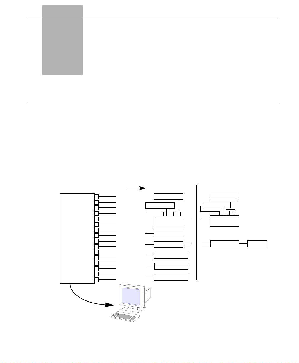
Chapter
1
Access Manager Overview
This chapter describes the functions and features of
Acces sManage r2000.
Functions
Access Manager 2000 is an IBM PC-based (or 100% IBM-compatible)
software program that allows you to perform numerous administrative
operations on a DS1 (T1) transmission network. Figure 1 -1, “Access
Manager 2000 set up”, illustrates how the host computer connects to the
local devices which, in turn, are connected to the remote devices through
a DS1 (T1) network.
Figure 1-1 Access Manager 2000 set up
Comlines to
1
2
3
4
Host PC
running
Access
Manager
5
6
7
8
9
10
11
12
13
14
15
16
Local Devices
Node
Node
Statistical
Multiplexer
Node
Mode
Alarm Printer
On-line Printer
Report Printer
Remote Devices
Node
Node
Statistical
Multiplexer
Mode
Node
keyboard/monitor
Access Manager 2000 User Manual
1-1
Page 32

Access Manager Overview
You can set up Access Manager to meet your specific network needs. For
example, you can edit the system date and time, add users and passwords
to the system, define the Access Manager communication ports and data/
report printers, and establish the performance data collection parameters
(i.e., define polling hours and allocate database storage space).
Network
Configuring
Status and
Performance
Monitoring
Through Access Manager, you can c onf i gur e Verilink DS1 (24 chan n els),
DS0 (single channel), and subrate circuit elements for proper operating
modes and for performance data collection. Each circuit element is
associated with a parent node, which provides the interface to Access
Manager. These nodes may also be configured.
Access Manager maintains a database of the configuration of each node
and its associated circuit elements. This database includes the
performance data collection (for example, alarm thresholds) and
reporting options, the interface to Access Manager options, and the DS1
(for example, line coding, and framing format), DS0, and subrate
operating characteristics options. The configuration functions of Access
Manager also allow you to define each circuit in the network for
performance data analysis and testing (for example, signal output during
loopback).
Access Manager allows you to download new architecture to any Access
System 2000 circuit element. New architecture may include feature or
performance enhancements or changes to a circuit element’s basic
function.
Access Manager provides local and remote non-disruptive status and
performance monitoring of Extended Superframe (ESF) DS1
transmission circuits from a central site (typically a hub office). You can
access any circuit element to retrieve current status and performance data.
You can also tell Access Manager when to poll the associated far-end
circuit elements for performance and status data. Polling allows you to
schedule storage of more than 24 h ours of dat a for histor ical analy sis. Th e
performance data can be archived for future reference.
Alarm and System
Ev en t Rep orting
1-2
Access Manager 2000 User Manual
Access Manager has alarm reporting features which indicate trouble
conditions in the circuit elements it is accessing. (For example, a CSUtype circuit element reports an alarm to Access Manager whenever it
Page 33

Network Elements
loses the incoming signal from the equipment or the network, or if the
operator-defined bit error rate threshold in either transmission direction
has been exceeded.)
In addition to alarm reports, the performance data and system events can
be logged for your review. An example of performance data reports is the
Errored Seconds re cord. System events logged include user log in, log
out, and Access Manager system restart.
On -line Access
and Testing
Conditions
Monitored
Access Manager allows you to access circuit elements and view their
current configuration and status. Once an element is accessed, you can
also activate and deactivate loopbacks on it for circuit testing and
troubleshooting. In addition, some elements can be commanded to send
and receive test signals for further assistance in testing and
troubleshooti ng.
The network (NET) and equipment (EQPT) conditions monitored by
Access Manager 2000 include:
■ On the network side:
• Bit Error Rate (BER)
• Errored Seconds (ES)
• Errored Seconds-Line (ES-L)
• Unavailable Seconds (UAS) Thresholds Exceeded
• Loss of Signal (LOS)
• Payload Loopback (PLB) or Line Loopback (LLB)
■ On the equipment sid e:
• Loss of Signal/Low Density
Network Elements
• Equipment Loopback (ELB) or Repeater Loopback (RLB)
• BER, ES-L, ES, and UAS Thresholds Exceeded
A network consists of these network elements:
Access Manager 2000 User Manual
1-3
Page 34

Access Manager Overview
■ Nodes
■ Circuit Elements
■ Circuits
■ Routes
Figure 1 -2, “DS1 Network Elements” shows the network elements as
they are defined by Access Manager.
Figure 1-2 DS1 Network Elements
ACCESS
MANAGER
2000
551VST MLS
(Near End)
AS2000
(Near End)
Node / Circuit Element
551VST LIST 2 CSU
EQPT
EQPT
(Near End)
EQPT
Circuit Elements
4016 L1 CSU
4016 L1 CSU
Circuit Elements
NCC 2020
DIU 2130
DS1 Facility
DS1 Facility
DS1 Facility
DS1 Facility
Circuit Element
FAR END
Circuit Element
FAR END
FAR END
Circuit Element
FAR END
EQPT
EQPT
EQPT
1-4
Data Port
Data Port
EQPT
AS2000
(Near End)
Data Port
EQPT
Data Port
A node is any equipment that has a single-point Access Manager port
(i.e., to which Access Manager can connect in order to access its circuit
elements for network management). The single point of access may be in
a variety of modes.
Access Manager 2000 User Manual
TAC 2010
DIU 2130
Circuit Elements
NCC 2020
DIU 2130
NCC 2020
DIU 2130
DS1 Facility
DS1 Facility
DS1 Facility
CIRCUIT
FAR END
Circuit Element
FAR END
FAR END
EQPT
EQPT
EQPT
Page 35

Network Elements
The modes of access for near-end nodes are standard implementations of
RS-232 interface method s, that is, direct, daisy-chained, through a
statistical multiplexer, or by modem. The mode of access for far-end
nodes is through the ESF Data Link through the near-end node access.
Since the functional specifications of the various Verilink network access
systems differ, Access Manager presents a different set of menus for the
two different types of nodes.
The two basic types of nodes are:
■ AS2000 type node (includes Access System 2000 and ConnecT1
Plus network management systems). ConnecT1 Plus is a low-cost
implementation o f AS2000 hardware avail able in a dual-line shelf
configuration only
AS2000 and ConnecT1 Plus nodes can have up to four shelves per
node. ConnecT1 Plus nodes have only dual-line shelves. AS2000
nodes can have a combination of dual-line and multiline shelves.
However, of the four possible shelves in an AS2000 node, no more
than two can be multiline shelves.
■ 551VST t yp e nod e (551VST type single-line nodes; SIM, NC/E,
551VST ML List 1, and 551VST ML List 2 multiline nodes).
This manual presents information mainly through menu descriptions.
Access Manager has two types of menus:
■ The AS2000 type of menus that reflect the f unctions of AS200 0 and
ConnecT1 Plus Nodes.
■ 551VST type menus for the other types of nodes.
The various configurations for these nodes are described in the following
section.
Si ngle-Line Nodes
The single-line nodes with which Access Manager 2000 interfaces are as
follows:
■ 551VST List 1/A CSU
■ 551VST List 1/B CSU
■ 551VST List 2 CSU
Access Manager 2000 User Manual
1-5
Page 36

Access Manager Overview
Dual-L ine Nodes
■ ConnecT1 Plus: Accesses up to four dual-line shelves containing up
to 2 circuit elements (CCC 1020, TAC 1010, DIU 1130, and
TIU 1850) per dual-line shelf.
■ Access System 2000: Accesses up to four dual-line shelves
containing up to 2 circuit elements (NCC 2020, TAC 2010, DIU
2130, and TIU 2850) per dual-line shelf.
Access Manager connects to the master NCC 2020, a plug-in module,
which is also a circuit element. The AS2000 is also available in multiline
node configurations.
Multiline Nodes
The multiline nodes with which Access Manager interfaces are shown in
Figure 1 -3, “Typical AS2000 Multiline Configuration,” on pa ge1-7.
1-6
Access Manager 2000 User Manual
Page 37

Figure 1-3 Typical AS2000 Multiline Configuration
Network Elements
ACCESS
MANAGER
2000
TAC TAC TAC
DIUDIU
MASTER
NCC
SHELF #1 SHELF #2
RS 232D DAISY CHAIN
DIUDIUDIU
DIU
MASTER
NCC
SHELF #1
RS 232D
■ SIM: Accesses one 551VST MLS Shelf containing up to ten circuit
elements (4016-R CSUs). Access Manager connects to the SIM (a
plug-in module in the shelf).
To next node
■ NC/E: Accesses up to five 551VST MLS Shelves containing up to
ten circuit elements (4016-R CSUs) per shelf. Access Manager
connects to the NC/E module.
■ 551VST ML List 1 Accesses up to two 551VST Multiline Shelves
containing up to 14 circuit elements (4016 List 1 and/or List 2
CSUs) per shelf. Access Manager connects to the NMC List 1
module.
■ 551VST ML List 2 Accesses up to two 551VST Multiline Shelves
containing up to 14 circuit elements (4016 List 1 and/or List 2
CSUs) per shelf. Access Manager connects to the NMC List 2
module.
Access Manager 2000 User Manual
1-7
Page 38

Access Manager Overview
■ Access System 2000 Accesses up t o two multiline shelves
containing up to 13 circuit elements per shelf (NCC 2020, TA
2010, DIU 2130, DIU 2140, and TIU 2850). Access Manager
connects to the master NCC 2020, a plug-in module which is also a
circuit element. Access System 2000 is also available in a dual-line
configuration ; see previous page under Dual-Line Nodes.
Only AS2000 and ConnecT1 Plus nodes can be daisy-chained. The
master NCC 2020 or CCC 1020 normally occupies the first slot of the
first shelf in each type of node. Refer to the Access System 2000 and
ConnecT1 Plus manuals for more information about the shelves, their
controller modules, and circuit elements.
Circuit Element
Note:
You cannot mix AS2000 hardware and ConnecT1 Plus hardware
on the same shelf
A circuit element is a single module of the parent node to which Access
Manager is connected. If the parent node is a single-line module, such as
a 551VST List 2 CSU, it has only one circuit element. If the parent node
is a multiline module, such as an AS2000 or ConnecT1 Plus, a circuit
element is a plug-in module in one of the shelves controlled by the node.
This module is identified by the parent node’ Node Name and a [shelf,
slot] index. The types of circuit elements are:
■ Single-Line Circuit Elements
■ Dual-Line and Multiline Circuit Elements
Single-Line Circuit Elements
The single-line circuit elements with which Access Manager interfaces
are as follows:
551VS T L i st 1/A CS U Includes the 551VST List 1 and 551VST List 1/A
CSUs.
551VS T L i st 1/B CS U Single-line CSU.
551VS T L i st 2 CSU The Verilink single-line CSU has the same hardware
as the 551VST List 1/B. It also has these additional
features: automatic alarm reporting, 9600 baud direct
connection, and support f or the Hayes
modem protocol.
1-8
Access Manager 2000 User Manual
Page 39

Network Elements
Dual-Line and Multiline Circuit Elements
The multiline circuit element plug-in modules with which Access
Manager interfaces are as follows:
4016R
4016 L i s t 1
4016 L i s t 2
CCC 1020
TAC 1010
DIU 1130
TIU 1850
NCC 2020
TAC 2010
DIU 2130
DIU 2132
DIU 2140
TIU 2850
Plug-in CSU module in 551VST MLS shelves.
Plug-in CSU module in 551VST ML List 1 or 2 shelves.
Plug-in CSU module in 551VST ML List 1 or 2 shelves.
Plug-in CSU module in ConnecT1 Plus shelves; it can also
function as the node for ConnecT1 Plus shelves.
Plug-in CSU module in ConnecT1 Plus nodes.
Plug-in module in ConnecT1 Plus shelves providing high
speed data features.
Plug-in module in ConnecT1 Plus shelves providing timing
from external clock for interface between DIUs and CSUs.
Plug-in CSU module in Access System 2000 shelves; it can
also function as the node for AS2000 shelves.
Plug-in CSU module in Access System 2000 nodes.
Plug-in module in Access System 2000 shelves, providing
high speed data features.
Plug-in module in Access System 2000 shelves, for Switched
Multi-megabit Data Service.
Plug-in module in Access System 2000 shelves, providing
subrate digital data service feature.
Plug-in module in Access System 2000 shelves, providing
timing from external clock for interface between DIUs and
CSUs.
Refer to the hardware manuals for more information on these plug-in
modules.
Ci rcuit
A circuit is the combination of any two network CSU circuit elements
and their interconnecting DS1 facility, which have Access Manager
access in a DS1 network.
Since all polled performance data is stored in the database by parent node
name and circuit element number, the circuit definition contains this path
for a circuit element whose performance data is collected through the
ESF Data Link.
Access Manager 2000 User Manual
1-9
Page 40

Access Manager Overview
The circuit definition is also used by Access Manager 2000 during data
analysis. This allows you to access the data stored in both circuit elements
by the associated circuit name. The circuit definition is also used during
the configuratio n of a far-end CSU through the ESF D ata Link.
Route
circuit end points as accessed by Access Manager. For Acce ss Manager, a
circuit and a route are functionally equivalent.
Access Manager Connections
Access Manager supports fiv e types of network m anagement ports. These
connect Access Manager to the devices it monitors. This information is
used in Chapter 4, C onfigurin g Access Manager when configuring the
Comlines of the host PC.
■ Direct-connect port. This port can be:
• Hardwired to the network device.
• Connected through a pair of ful l-tim e (d edicat ed) mod ems us ing
a dedicated facility.
• Connected by a dedicated port into a multiplexer and conveyed
in the multiplexer’s payload.
■ Remote dial port. The remote dial port can dial-out and receive
dial-in calls from network devices. This port uses the Hayes
command set at 1200 or 2400 baud.
■ Remote dial-in port. This type of port can only answer dial-in calls
from network devices (normally used with INWATS lines).
A route consists of the two network circuit elements at DS1 network
AT
1-10
■ Routing port. The routing port is designed to connect to a routing
■ Serial device interface. This is a serial output-only port with no
An optional external Hayes
answer feature to automatically forward changes in the status or alarm
conditions of the near-end or far-end CSUs to a central management site.
Access Manager 2000 User Manual
multiplexer such as a ComDesign RS2000 Statistical Multip l exer.
Multiple network devices may be connected through this type of
multiplexer.
flow control. Sends alarm messages to a printer or to another
computer using the Accumaster protocol.
-compatible modem uses the auto-dial/auto-
Page 41

Appendix B "Modem Configuration" provides the modem configuration
information.
Access Levels
Access Manager provides four levels of user access protection:
■ Level 1: View data only
■ Level 2: I ncludes Level 1 capabilities plus limited non-service-
affecting operational changes.
■ Level 3: Includes Level 1 and 2 capabilities, plus full maintenance
control (circuit element loopbacks, testing, etc.).
■ Level 4: Includes all preceding Level capabilities, plus Access
Manager system administration (adding/deleting users, archiving
database files, setting passwords, etc.).
Access Manager 2000 Main Menu
Access Levels
Access Manager is divided into five categories of operations. Each of
these may be selected from Access Manager’s Main Menu. This menu
appears after you start Access Manager and log in.
Figure 1-4 Access Manager 2000 Main Menu
The Main Menu provides access to five major menus. The sub-menus list
categories of operations you can perform with Access Manager. Each
sub-menu also has options, additional sub-menus, and screen displays to
assist you in selecting and performing an operation.
Access Manager 2000 User Manual
1-11
Page 42

Access Manager Overview
Figure 1 -5, “Access Manager 2000 menu tree ,” on page 1-13, provides an
overview of the five major menus. Next to each menu is a short
description of its activities.
Following that figure are diagrams of each of the five major menus and
their options. These provide you with a quick review of what’s in each
major menu.
1-12
Access Manager 2000 User Manual
Page 43

Access Manager 2000 Main Menu
Figure 1-5 Access Manager 2000 menu tree
This diagram provides a view of the major Access Manager 2000 menus. The Main Menu supports five major menus:
Utilities, Alarm Status, Configuration, Online (Access)
, and
Database Access
.
AM2000 Main Me
Utilities
Menu
Alarm Status
Menu
Configuration
Menu
On-Line (Access)
Menu
This allows you to configure the Access Manager. Here you set up certain
“housekeeping” functions like date and time, what comlines are used, and
where you want reports sent and printed.
These commands affect the active alarm counter and the alarm log database.
• An active alarm is an alarm record in the log which has not been manually
deactivated by the user and cannot be deleted or archived.
• Alarms that are deactivated can be deleted and/or archived.
Allows you to define or edit the configurations of the nodes, circuit
elements, circuits, and routes in the network.
Allows you to access nodes and circuit elements for testing and maintenance
functions.
• Through this menu you can acquire the network configuration, status, and
DS1 performance data.
• You can also reset the user registers
and perform out-of-service testing.
Database Access
Menu
Allows you to process DS1 performance data stored in the Access
Manager database.
Not all sub-menus will be accessible at all times. Whether or not a submenu is accessible depends on the type of node you are accessing.
Access Manager 2000 User Manual
1-13
Page 44

Access Manager Overview
Utilities
The Utilities option of the Main Menu allows you to configure the
Access Manager system.
It has the following major branches:
Utilities
Menu
Date/Time
Installation
Site
Report
On-line
Alarm
Hour
Quotas
Comlines
User Definitions
Event Log
Code Download
1-14
Date / Time
This option allows you to set the system date and time.
Installation
This option allows you to define the system site name, define the system
printer(s), select the hour to start polling for performance data, allocate
database records (for alarms, event logs, and performance data), and
define serial communications (COM) ports.
User Definitions
This option allows you to specify user names, passwords, and access
levels.
Access Manager 2000 User Manual
Page 45

Access Manager 2000 Main Menu
Event Log
This option allows you to view, print, and archive system eve n ts such as
user log in, user log out, time of scheduled data polling, Access Manager
start-up, shut-down, etc.
Code Download
This option allows you to download new firmware cod e in order to update
the element firm ware or to provide custom applications to a circuit
element (NCC 2020, TAC 20 10, DIU 2130, or DIU 2140). Only Ver ilink
Access System 2000 modules have this Advanced Programmable
Architecture (APA) feature. APA is not available for any other Verilink
single-line or multiline systems.
Alarm Status
The Alarm Statu s Menu comma nds affect the a ctive alarm counter and the
alarm log database. An active alarm is an alarm record in the log that has
not been manually deactivated by the user and cannot be deleted or
archived. Alarms that are deactivated can be deleted and/or archived.
It has the following major branches:
Alarm Status
Menu
Clear
Deactivate
View Active
List Active
Print All
Archiv
Clear
This command clears the automatically acknowledged alarms counter.
Access Manager 2000 User Manual
1-15
Page 46

Access Manager Overview
Deactivate
This command deactivates alarm records and makes them available for
deletion and/or archiving.
View Active
This command displays all alarm records that have not yet been
deactivated.
List Active
This command prints all alarm records that have not yet been d eactivated.
Print All
This command prints all alarm records whether or not they have been
deactivated.
Archive
This command allows you to print, transfer to disk, and/or delete
deactivated alarm records.
Configuration
1-16
Access Manager 2000 User Manual
The functions under the Configuration menu allow you to define or edit
the configurations of the nodes, circuit elements, circuit, and routes in the
network.
It has the following major branches:
Configuration
Menu
Node
Element
Circuit
Route
Page 47

Access Manager 2000 Main Menu
Node
A node is any equipment that has single-point Access Manager access
(i.e., to which Access Manager can connect in order to access its circuit
elements for network management). The single point of access may be in
a variety of modes. The mode of access for far-end nodes is through the
ESF Data Link. The mode of access for near-end nodes is either by direct
connection or through a statistical multiplexer or modem; additionally,
one node controller can access another node controller through a daisy
chain.
Circuit Element
A circuit element is a single module of the parent node to which Access
Manager is connected. If the parent node is a single-line module, such as
a 551VST List 2 CSU, it has only one circuit element. If the parent node
is a multiline module, such as an AS2000 type, the node may h ave s everal
elements.
Ci rcuit
A circuit consists of any two network circuit elements, and the
interconnecting DS1 line, that have Access Manager access in a DS1
network.
On -line Access
Route
A route consists of the two network circuit elements at DS1 network
circuit end points as accessed by Access Manager. For Acce ss Manager, a
circuit and a route are functionally equivalent.
The On-line Menu allows you to access nodes and circuit elements for
testing and maintenance functions. Through this menu, you can acquire
the configuration, status, and DS1 performance data of the network. You
can also reset the user registers and perform out-of-service testing.
Access Manager 2000 User Manual
1-17
Page 48

Access Manager Overview
It has the following major branches:
On-Line (Access)
Menu
Display
Access Range
Element Configura tion Display
Circuit Status Diagram
Status Element
User Statistics
Telco Statistics
Reset User Registers
Performance Data Retrieve
Barchart Display
Loopbacks
1-18
Note:
Display
For a multiline node, this command allows you to view the multiline
node’s hardware configuration, status, controll er firmware, and hardware
revisions.
Access Range (Access CSU)
This command allows you to select a network circuit element. For
multiline CSU nodes, you can access either a single CSU or a range of
sequential CSUs. For Access System 2000 nodes, you can access NCCs,
TACs, or DIUs.
Access Manager 2000 User Manual
Select Test
The actual commands listed in the On-line menu depend on
which type of CSU or multiline node is accessed. The following
commands are typically found in this menu:
Page 49

Access Manager 2000 Main Menu
Element Configur ation and Status-Element (Element Status)
These commands show the status, configuration, firmware, and hardware
revisions of the CSUs selected by accessing a CSU range. For Access
System 2000 nodes, the NCC, TAC, and DIU configuration status may
also be viewed.
Circuit Status Diagram
This command allows you to access and graphically display the near-end
CSU and associated far-end CSU to which a DS1 circuit is connected.
User Statistics
This command computes and displays the percentages of available and
error-free seconds, plus other user performance data for the selected CSU
and far-end CSU.
Telco Statistics
This command computes and displays the percentages of available and
error-free seconds, plus other Telco performance data for the selected
CSU and far-end CSU.
Reset User Registers
This command allows you to reset the user performance registers and
error event registers in both the near-end and far-end CSUs.
Performance Data Retrieve
These commands allow you to obtain the 1-hour or 24-hour DS1
performance data stored in a CSU or its associated far-end CSU. You can
view either the User data or the Telco data. If the CSU is an AS2000 type,
then EQPT data (as well as extra network registers) are available.
Barchart Display
This menu option displays performance data in bar chart format for the
current 24-hour period. Bar chart displays for historic performance data
are available through Database Access.
Access Manager 2000 User Manual
1-19
Page 50

Access Manager Overview
Loopbac ks
This command allows you to activate or deactivate a loopback at the nearend or far-end CSU, send an inband loop -up or l oop-down code to the fa r end CSU, or activate or dea ctivate an ALL-ONEs test signal to the far-end
CSU. Loopbacks can help you isolate circuit troubles to either the DS1
network or the CSU at either end. For Access System 2000 and
ConnecT1 Plus nodes, the loopback command also lets you activate and
deactivate CSU loopbacks with ANSI T1.403-compatible command
messages.
Select Test
This command is available only when interfacing with an Access System
2000 or ConnecT1 Plus nod e. It allo ws you to perform di agnost ic tests o n
a circuit connected to the node. You can apply a DS1 test signal from an
NCC 2020 or CSU 2010 to the associated circuit for testing. You can
similarly apply a test signal to EQPT (i.e., data port) channels of a DIU
2130 or DIU 2140 for path verification.
Database Access
1-20
Access Manager 2000 User Manual
The functions under the Database Access menu allow the processing of
DS1 performance data stored in the Access Manager database.
It has the following major branches:
Database Access
Menu
Report
Archiv
Report
This command analyzes and reports on the performance data stored for
selected network elements over a selected date and time range through the
use of standard filters or user-selected thresholds.
Archive
This command allows you to print performance data records, export them
to a spreadsheet or database system, or delete them.
Page 51

Chapter
2
Installing Access Manager
This chapter provides instructions for installing Access Manager. It also
describes the host personal computer and peripheral equipment
requirements for Access Manager operation.
Equipment Installation
Before installing Access Manager, verify that your system meets the
requirements listed below. These basic system requirements have been
tested and are known to be compatible with Access Manager.
Minimum System
Requirements
These are the minimum system requirements for Access Manager.
Parameter Requirements Recommendations a nd Notes
Host computer
model
Operating
system
RAM Host:
Hard disk
memory
Recommended
software drivers
AM2000 may be installed on
one of the following:
• IBM PS/2 Model 80
• AT&T 6386/SX WGS
• 100%-compatible 386 PC
DOS version 5.0 or later on the
host PC. DOS must be fully
and properly installed.
640K of base memory
Accumaster:
Total:
Use a minimum 80-megabyte
hard disk with fast access (less
than 20 milliseconds).
• himem.sys
•smartdrv.exe
192K
4 megabytes minimum
Use a color monitor with the
appropriate graphics adapter.
A VGA monitor is recommended.
To use expanded or extended onboard memory, see your application
engineer for the specifications on
configuring your system.
Program and overhead files take 2
megabytes. The rest is for data
storage.
These are very strongly
recommended.
Access Manager 2000 User Manual
2-1
Page 52

Installing Access Manager
Parameter Requirements Recommendations a nd Notes
Communication
ports
Modems
Pri nter
Statistical
Multiplexer
X.25 PAD
Management
software
Remote terminal
• 2 serial po rt s (if a dial-up
interface is being used) and
1 printer port
•Hayes
• AT&T 2224 (2400 baud
pcANYWHERE III can be used
with Access Manager to
enable start-up and/or control
of Access Manager from a
remote terminal.
• DEC VT100, o
• VT100 emulator
1200, 2400, or 9600
baud (external
external
Also compatible
• DigiBoard DigiCHANNEL MC/8
(PS/2 Model 80 compatible) serial
communications board (with 8
serial ports)
• An internal Hayes
only if it is configured to use
communications Port 1 (COM1) o
COM2.
• If Access Manager uses more
than two ports, using an internal
modem is not recommended.
Epson LQ-1050 (132-column) printer
The ComDesign RS2000 or SPX
series Statistical Multiplexer,
operating at up to 9600 baud, can b
added to an Access Manage
network as a routing multiplexer to
concentrate the communication lines
between Access Manager and
connected CSUs.
Tested with NET TX7000 PAD.
Do not use newer versions of
pcANYWHERE.
The remote terminal supported by
Access Manager through
pcANYWHERE software. This is
used for remote network
management applications, including
running Access Manager remotely
from an Accumaster site.
:
modem works
2-2
Hard disk storage consid erations
The maximum available hard disk space is dependent on the size of your
hard drive and what version of DOS your PC is running. Up to a
maximum of 30 megabytes hard disk space can be available for Access
Manager data collection when using DOS 3.3. Newer versions of DOS
(for example, DOS 5.0) will allow for proportional storage space
depending on the size of the hard disk.
Access Manager 2000 User Manual
Page 53

Equipment Installation
Note:
Verilink recommends that a 80-me gabyte hard drive be used when
running Access Manager.
Each alarm record uses 62 bytes of memory, each data record uses up to a
maximum of 150 bytes of memor y, and eac h ev ent record uses 58 bytes of
memory. As the number of records allocated for a particular type are
filled up, the oldes t records are deleted to make room for the ne w record s.
The space used on the hard disk for data records, alarm records, or event
log records can be freed by using the Archive option. This option
allows you to store records to diskette and/or delete the records entirely.
Each of these three types of records (data, alarm, event log) has
associat ed .DAT and . K E Y files. To decr ease a record’s asso c iated .DAT
and .KEY files to minimum size and thereby release disk space, all
records of a type (for example, all alarm records) must be deleted from
the database.
To minimize the space used for data collection, the program stores only
records that are non-ZERO.
Access Manager 2000 User Manual
2-3
Page 54

Installing Access Manager
Software Installation
This section provides instructions for installing Access Manager 2000
software on your host PC’s hard disk.
The Access Manager software is provided on two diskette sets:
Both diskette sets have identical content. The INSTALL.EXE program
file is on Diskette # 1 of either disk set. Use the one which fits your floppy
drive.
When you install Access Manager 2000, the following files are copied to
your hard di sk.
Table 2-1 Access Manager Installation Files
ACTIVE.KEY ALAR MLOG.DAT ALAR MLOG.KEY ALRMDESC.DAT
ALRMDESC.KEY AM 2000.EXE AM2000.OVL AM2000.SIG
BUS.KEY CETABLE.DAT CETABLE.KEY CFROM.KEY
CIRCUIT.KEY CNFSTAT.DAT CNFSTAT.KEY COLORATT.DAT
COMLINE.DAT COMLINE .KEY CON FIG.SYS CTO.KEY
DATALOG.DAT DATA LOG.KEY DBVERS.DAT DTEVLOG.DAT
DTEVLOG.KEY EQUIPMNT.DAT EQUIPMNT.KEY LEVEL.DAT
LEVEL.KEY LOCATION.KEY MONOATT.DAT NETVLOG.DAT
NETVLOG.KEY NODE.DAT NODE.KEY NODEID.KEY
POINT.DAT POINT.KEY PORT.DAT PORT.KEY
PRENNAME.KEY RANDC.DAT RANGE.DAT RANGE.KEY
README.DOC RFROM.KEY ROUTE.K EY RTO.KEY
SCNAME.KEY SDDNAME.KEY SDNAME.KEY SELECTED.DAT
SELECTED.KEY SIGCSU.DAT SIGDDSU.DAT SIGDSU.DAT
SITE.DAT SITE.KEY SSUPARM.DAT SSUPARM.KEY
TYPE.KEY UN CLRALM. DAT U NCLRALM.KE Y USER.DAT
USER.KEY USERLOG.DAT USERLOG.KEY VERINET.DBD
■ a 3.5-inch (720 kilobyte density) diskette set, and
■ a 5.25-inch (1.2 Mb density) diskette set
2-4
Access Manager 2000 User Manual
Page 55

Software Installation
Two working files are generated during Access Manager operation. The
files function as transaction files for various program functions and to
allow restoration of the database in case of power loss or a computer
reset. They are:
VISTA.TAF VISTA.LOG
Note:
Refer to the
README.DOC file on Access Manager Diskette # 1
for last-minute information and any restrictions placed on the
Access Manager revision being installed.
Use the following procedure if you are installing Access Manager for the
Installing a new
Access Manager
first time and if you have never installed Access Manager on your host
PC.
system
To install a new Access Manager system:
1. Insert Diskette # 1 into drive A: (or another flopp y diskette drive).
2. To access that drive, type A: (or the other disk drive name) and
Enter
press .
3. At the A: prompt, type INSTALL and press . The
INSTALL program’s main menu then appears.
4. Select the Database Stats option, and verify that you have at
least two megabytes of space available on the hard disk.
5. After verifying disk space, the INSTALL program’s main menu
reappears. Select the Install option.
Enter
6. Respond to the subsequent prompts to complete the installation of
Access Manager in the AM2000 directory.
7. Before starting Access Manager, you must verify the location and
content of your CONFIG.SYS file.
Verifying the CONFIG.SYS file
For Access Manager to run, you must have a CONFIG.SYS file which
satisfies two requirements. It must:
Access Manager 2000 User Manual
2-5
Page 56

Installing Access Manager
■ reside in the r oot directory of your hard disk’s boot drive (normally
drive C), and
■ contain the following lines:
FILES=24
BUFFERS=20
If a CONFIG.SYS file did not exist in the install
This command line sets the maximum number of files
that can be open at one time. The minimum number
required for Access Manager is 24, but the number can
be larger, if required by other programs.
This command line sets the number of disk buffers
DOS allocates in memory when it starts. The minimum
number required by Access Manager is 20, but this
number can be greater if needed by other programs.
drive directory, then
the one from the database disk was copied to it. However, if the install
drive (for e xample, drive D:) is not the same as the boot d r ive (nor mally,
drive C:), you’ll need to determine whether or not the boot drive has an
appropriate CONFIG.SYS file.
The following instructions assume that your host PC boots from the C:
drive. If the boot drive letter is oth er than “C”, use that let ter in place of
“C” in the steps below.
T o determine whether the boot drive has an appropriate
CONFIG.SYS
1. At the DOS C:\> prompt, type CD\ and press .
2. At the C:\> prompt, type CONFIG.SYS and press .
file:
Enter
Enter
2-6
Access Manager 2000 User Manual
a. If DOS returns the error message FILE NOT FOUND, a
CONFIG.SYS file does not exist in yo u r syst e m .
Then, you must follow the instructions for copying the
CONFIG.SYS file to the root directory of the boot drive.
b. If a CONFIG.SYS file exists, it will open. Verify that the
FILES
and BUFFERS lines exist in CONFIG.SYS. Verify
that the number of files and buffers called by these lines is
sufficient. If the lines d on’ t ex ist or the number to the right of the
equal (=) sign is too small, you must follow the directions for
modifying the CONFIG.SYS file.
Page 57

Software Installation
To copy the CONFIG.SYS file to the root directory of the boot drive:
1. Type C: and press to return to the boot drive.
2. Type CD\ and press to return to the root directory on the
Enter
Enter
boot drive.
3. Insert Diskette #1 of Access Manager 2000 into drive A.
4. A t the boot drive prompt, type COPY A: CONFIG.SYS and
Enter
press .
The CONFIG.SYS file is created in the root directory.
5. Remove the diskette from drive A.
Note:
The new values for FILES and BUFFERS are not in effect until
the host PC is rebooted and DOS is restarted.
6. Reboot your system to activate the new values before starting
Access Manager. Otherwise, you will not be able to log into Access
Manager.
To modify an existing CONFIG.SYS file:
The existing CONFIG.SYS file must be modified if it does not contain
FILES=24 (or greater) and BUFFERS = 20 (or greater).
1. Modify the CONFIG.SYS file with EDLIN (the text editor for
DOS) or with any text editor or word processor with an ASCII text
editor option.
2. Reboot the system after you change the CONFIG.SYS file. The
values for FILES and BUFFERS are not in effect until you do.
Use the following procedure if Access Manager is installed on your host
Updating an
existing Access
Manager system
PC and you want to upgrade to the current version.
To update an existing Access M anager syst em:
Access Manager 2000 User Manual
2-7
Page 58

Installing Access Manager
1. If the current Access Manager directory is named AM2000, create a
backup directory named, for instance, AM2000.BAK.
2. Copy the current directory’s contents to AM2000.BAK so that the
current directory can be used by the update.
3. Insert Diskette # 1 into drive A: (or another floppy diskette drive).
4. To access that drive, type A: (or the other diskette drive name)
and press .
Enter
5. At the A: prompt, type INSTALL and press . The
Enter
INST ALL program’s main menu should appear
6. Select the Database Stats option to determine if the host PC
has enough space to hold the new software and modified database.
You need approximately 2 megabytes of hard disk space for the
software files, plus space equal to the size of your Access Manager
database. To calculate the size of the Access Manager database, add
together all files which have the extensions .DAT and .DBD.
For example, if you are updating an Access Manager installation
with an 8-megabyte database, you need 2 + 8 = 10 megabytes of
space on your hard disk.
TIP
The Database Stats selection can be u sed at any time to dete rmine
database size and available hard disk space.
7. You need to decide how you want the database to be affected.
• To convert the existing database to the latest Access Manager
format, select the Full Update option. This is the
recommended method.
• To leave the existing database in its current format, select the
Partial Update option. This should only be used for
interim releases.
8. After choosing one of the abo v e , re spond to the subse quent pr ompts
to complete the selected action.
9. When the program prompts you for the new Access Manager
directory to be created, type AM2000.
2-8
Access Manager 2000 User Manual
Page 59

Software Installation
The INSTALL program then copies the Access Manager program
files and all blank database files into the newly created directory. It
transfers all data from the current database to the new database and
leaves the current database intact.
10. Now the installation is complete, and you need to update a few other
files:
If pcANYWHERE is being used:
a. Copy the pcANYWHER E files from the old Access Manager
directory into the AM2000 directory.
b. If changes have been made to the factory default settings, either
copy the .CFG file from the AM2000.BAK directory to the
AM2000 directory or reconfigure pcANYWHERE from the
start.
If you made changes to the COLORATT.DAT and
MONOATT.DAT
files:
a. You mus t make the same changes to the n ew COLORATT.DAT
or MONOATT.DAT files in the AM2000 directory.
b. This can be done with a standard ASCII text editor.
11. After the update is completed, go to the AM2000 directory and
start Access Manager.
12. When you’re sure that the new database is working properly, delete
the old database in the AM2000.BAK directory you created in
Step 1.
By using a start-up batch file, you can set up Access Manager to do one of
Creating a batch
file for automatic
start-up
the following:
■ start up automatically when your system boots up, or
■ start from any directory.
For automatic start-up whenever the host PC is powered up
, you can
modify an existing AUTOEXEC.BAT file in the DOS root directory.
For manual start-up from any director
, you can create a file called
AM2000.BAT (or anything else you like) in any directory which exists
in the DOS path. Once this file has been created and saved, you can type
Access Manager 2000 User Manual
2-9
Page 60

Installing Access Manager
AM2000 in any directory to start the program. The batch file
automatically changes to the Access Manager directory and starts the
Access Manager program.
In either case, you must use statements from Table 2-2, “Batch file
commands for automatic start-up,” on pag e2-10. All editing can be done
with an ASCII text editor, such as EDLIN.
Add the following lines to your batch file as required:
T able 2-2 Batch file comm ands for automatic start-up
Command line Function
CD drive:\AM2000
ANYWHERE AUTOMATIC
AM2000
AM2000/BW
AM2000/VT
AM2000/VT/BW
TZ = xSTn
To change to the directory where Access Manage
is installed. If the directory is other than
use that directory‘s name in lieu of
For “drive”, use your appropriate drive letter.
To start up the pcANYWHERE III p rogram.
To use a color PC.
To use a monochrome monitor with a color PC or
monochrome PC.
To start Access manager in the VT100 mode;
required if pcANYWHERE is used.
The
/VT
command causes Access Manager to
run its VT100 screens. This means that function
and other key combinations are shown on the
screen as the required key strokes used on a
VT100 terminal.
To start Access Manager in the VT100 mode on a
monochrome PC; required if pcANYWHERE is
used.
The
run in black-and-white mode.
If a remote computer is being used with:
• a VT100 terminal emulation progra
• an actual VT100 terminal
This is used to set the clock only if an Accumaster
interface is being used. See“Time Zone Setup for
Accumaster” on page2-14 for values of
/BW command causes Access Manager to
terminal emulation program capabilities
determine whether or not the /BW command is
required.
, then Access Manager
can be used in color mode by leaving off the /BW
command.
AM2000
AM2000
, then the
and
x
.
.
n
,
2-10
Access Manager 2000 User Manual
Page 61

Software Installation
After making any changes to your start-up batch file, save the file and
reboot your system.
Limitations
■ ProComm can operate in the color mode if the remote PC has a
color graphics card and monitor.
■ Due to the use of certain escape key combinations, Crosstalk XVI
cannot be used.
■ If Access Manager is to be used from a remote VT100 terminal
most of the time, the AUTOEXEC.BAT
file should first start up
pcANYWHERE and then start in VT100 mode.
■ If Accumaster is being used, the line SET = xSTn must precede
any command that automatically starts Access Manager in the
AUTOEXEC.BAT
file.
This section describes how to se t up a remote terminal and k eyboard. This
S etting up the
remote terminal
requires the installation of pcANYWHERE III.
pcANYWHERE is a remote access software program available from
1
Dynamic Microprocessor Associates. It lets you operate an IBM PC, XT,
AT, PS/2, or 100% IBM-compatible from a DEC VT1000 or VT1000
emulator at a remote location. The remote PC or terminal operates as the
monitor and keyboard for the local system.
You must install pcANYWHERE if Access Manager will be run with
Accumaster. pcANYWHERE permits the Accumaster operator to access
and control Access Manager from the Accumaster console.
Proper operation of pcANYWHERE requires the following:
■ a host PC with a minimum 192K of system RAM (45K of RAM is
used when pcANYWHERE is left resident.)
■ a host modem
■ a remote modem, and
■ a remote terminal (or a PC running terminal-emulator software) to
control the host PC.
1. All references to pcANYWHERE III throughout this document are generically called “pcANYWHERE”.
Access Manager 2000 User Manual
2-11
Page 62

Installing Access Manager
For detailed information on the installation or operation of
pcANYWHERE, refer to the manual supplied with it. Additional default
setting information regarding use with Access Manager is given in this
section.
To install pcANYWHERE in a host PC:
1. Install pcANYWHERE onto the host PC hard disk into the same
directory where Access Manager was installed. Typically, this
directory is named AM2000.
2. Copy pcANYWHERE files from the program diskettes into that
directory, as explained in the pcANYWHERE user’s manual.
The following pcANYWHERE III parameters settings should be used
when configuring the host PC:
pcANYWHERE
Parameter
Baud ra te
Com Port
Connect type
Co-pilot mode
The baud rate setting depends on the modem type in use.
This setting can range from 50 to 57600 baud, or it can be set
to Auto-baud. Access Manager works at 1200 and 9600 bau
with a modem or, if direct connect, up to 19200 baud.
The DEC VT100 default setting is 300 baud.
Alway
COM
There are 3 connection options:
Automatic Modem
following limitati ons.
•For
Direct Connect
set the log in parameters to
inactivity time-out to
•For a
Manual Modem
Either system keyboard may be made active. The normal
setting should be
Both Keyboards Active
Setting
Direct Connect,
, or
Manual Modem
, do not use any “log in”; that is,
Defaults
.
0
connection, use “log in”.
. Also set the
, with the
.
2-12
Access Manager 2000 User Manual
Page 63

Software Installation
pcANYWHERE
Parameter
Inactivi ty
time-out
Login
paramet ers
Terminal Type
Set to
No Time-out or 0 seconds, to allow
pcANYWHERE to hang up only if the remote modem hangs
up.
The inactivity time-out does not work unless it is set to less
than one minute. This is because in the remote terminal (/VT)
mode Access Manager updates the screen (current time
once every minute and pcANYWHERE treats this as activity.
The remote operator is responsible for dropping the line when
communications is complete.
This option allows you to set the login parameters (such as
the password). Selecting the
same login parameters to every remote caller.
This allows pcANYWHERE to know whether you are using a
remote PC or remote terminal to run the Host PC. Select
VT100.
Setting
Defaults option applies the
Remote Access Port
Access Manager 2000 requires that the host PC has one dedicated
communications serial port for access by a remote terminal or computer.
COM1 is normally assigned as the dedicated pcANYWHERE port. This
is the remote access port and is configured in the Host PC setup of
pcANYWHERE. COM2 and upward are then configured within Access
Manager.
Setting up
Accumaster
!
CAUTION
The default configuration of Access Manager includes COM1 as a
Comline Definition. It must be deleted from the database wheneve
using CO M1 as the remote access port with pcANYWHERE. When a
modem is used with the re mote access port, and pcANYWHERE is
configured for a modem, then pcANYWHERE automatically
configures the modem.
Accumaster is an AT&T network management system which can ma nage
alarm messages from Access Manager. When used together, Access
Manager sends alarms through a comport in an Accumaster protocol.
Setting this up requires the following:
Access Manager 2000 User Manual
2-13
Page 64

Installing Access Manager
■ Physical connections between the host PC and xxx.
■ Your host PC must be running pcANYWHERE.
■ You must be using the largest (-1000) Access Manager package.
■ You must use the Access Manager menus to set up a utility.
■ Your AUTOEXEC.BAT file must include the time zone variable,
TZ = xSTn. This must always accurately reflect the appropriate
standard time or daylight savings time.
Time Zone Setup for Accumaster
Since the alarms sent to Accumaster must be time-stamped and include
time zone, an environment variable (TZ) must be set up in your
AUTOEXEC.BAT file.
The following line should be added to the AUTOEXEC.BAT file prior to
any batch command that automatically starts Access Manager.
SET = xSTn
where x and n are filled in from Figur e2-3, Accumaster Time Zone
Chart”. For example, EST5 would be used in the Eastern Time Zone
when daylight savings time is not in effect.
2-14
Table 2-3 Accumaster Time Zone Chart
Time Zone Standard Time
Hawaii HST10 HST9
Alaska LST9 LST8
Pacific PST8 PST7
Mountain MST7 MST6
Central CST6 CST5
Eastern EST5 EST4
Atlantic AST4 AST3
The time zone string (for example, PST) is not critical, as long as it is
three characters long. The number following the string is critical because
it represents the number of hours difference from Greenwich Mean Time
(GMT), which must be included in all alarm records sent to Accumaster.
Access Manager 2000 User Manual
When/If Daylight Saving
Time is in Effect
Page 65

Software Installation
Before Starting Accumaster
Before Accumaster is run for the first time, the network should be
configured. In particula r, the Alarm output is configured (within Access
Manager) the same as conf iguring an Alarm Printer. Since only one alarm
output can be defined, the configuration of alarms being sent to
Accumaster precludes the use of a physical alarm printer. The
communications port to be used is configured as a Serial Device. If a
modem is used, it must be set to Auto Answer, as described in
AppendixB, "Modem Configuration".
Access Manager 2000 User Manual
2-15
Page 66

Installing Access Manager
2-16
Access Manager 2000 User Manual
Page 67

Chapter
3
Basics
Basic Display
Using Access Manager
This section provides you with information about:
■ screen appearance and content
■ using the keyboard and keystrokes
■ navigating between screens
This section discusses the basics of moving around in the Access
Manager screens.
U sing a color monitor
If you are in a View screen, or if the present access level prevents you
from making changes to a particular part of the database, the entries and
options appear in red. If you are in an Edit or Add screen and the access
level allows you to change an entry or option, the entries are displayed in
white on blue at the cursor position, and in blue on white for all other
positions.
Screens
When you first log into Access Manager, you’re presented with a
Username screen, shown in Fig ure 3-1, “Usernam e Screen,” on pag e3-2.
Access Manager 2000 User Manual
3-1
Page 68

Using Access Manager
Figure 3-1 Username Screen
Access Manager
serial numbe
input screen for user name
In this screen, you enter your username and, susequently, your password.
This logs you on to Access Manager 2000.
Once you’ve logged on, the Main Menu will appear. That screen, and all
other Access Manager 2000 screens, are framed within the boundaries of
the screen shown in Figure 3-2, “Basic display on host PC,” on page 3-3.
3-2
Access Manager 2000 User Manual
Page 69

Figure 3-2 Basic display on host PC
Basics
here Access Manager is located
number of current automatically acknowledged alarms
logged-in user name and access level
program revision level
Date and time by
system clock
main function key definitions
(in reverse video)
(manual or automatic)
number of active alarms
alarm mode
VERINET
Shows current node when in
On-line Access
Configuration
or
mode
Differences in displays when in VT100 mode
The personal computer and VT100 display the same information on their
respective screens, with the following exceptions:
■ Operating Access Manager locally on the personal computer results
in the display sho wing all commands as function keys (F1 to F10).
This is shown in Figure 3 -3, “Function key display at host PC,” on
page 3-4.
Access Manager 2000 User Manual
3-3
Page 70

Using Access Manager
Main function key definitions
(in reverse video)
Figure 3-3 Function key display at host PC
■ When operating Access Manager remotely with a VT100, the
display shows the commands as escape key combinations. If using a
personal computer keyboard, the function keys may still be used.
This is shown in Figure 3 -4, “Escape key sequence display at
VT100 terminal”.
Figure 3-4 Escape key sequence display at VT100 termina
function keys replaced by
escape key sequences
Men u s
3-4
Access Manager 2000 User Manual
Although we refer to almost all displays as “screens”, those screens
which allow you to select options are m enus. Menus eithe r provide access
to another menu or take you to a screen with fields for data entry.
Page 71
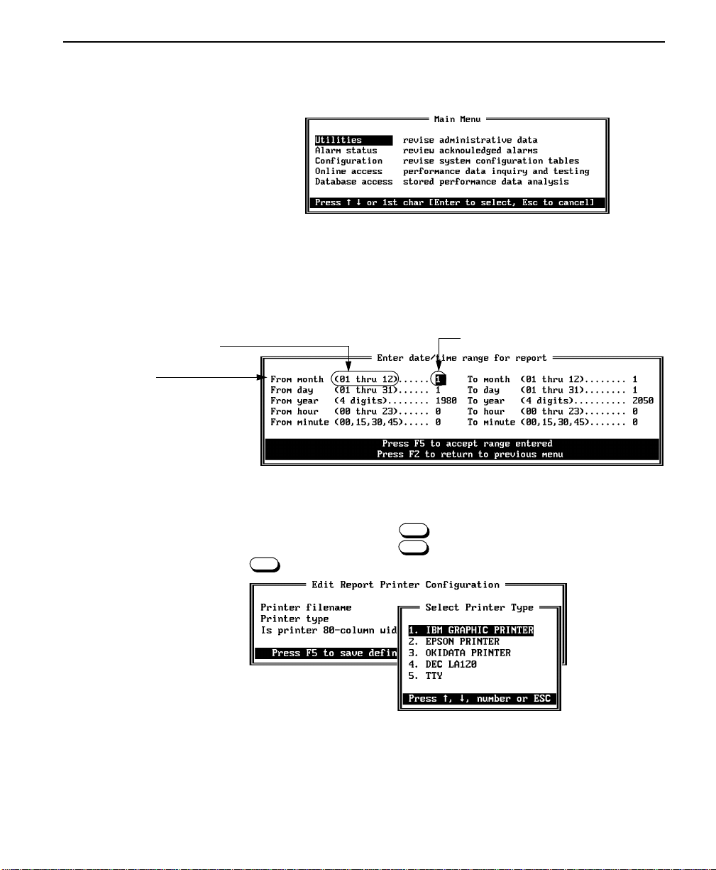
Basics
F8
F8
For example, the Main Menu, shown below, provides access to five other
menus.
If you select the Utilities option, the Utilities Menu appears.
Every field which calls for a choice shows the default or chosen option on
the right. When the available options are few, the options may be enclosed
in parentheses after the field text and before the option area on the right.
available options
field
option entry area
When multiple options are available for a field, the field’s text will
usually be followed by an or instructions at the bottom of the
screen will tell you to use to display options. When you press
F8
, a list of options will appear, superimposed on the current menu.
Access Manager 2000 User Manual
3-5
Page 72

Using Access Manager
Status Display
Status screens provide information directly from on-line data. Status
screens are “read only” and provide status information only for the
moment that you access the screen. The screen does not update itself. To
find out that a condition you see on the screen has changed, you would
have to exit out of the screen and then reaccess it.
Keyboard
Alarm notifications, however, do let you know immediately
if there is a
significant change.
This section describes the function keys, cursor movement keys, and
special keys used at a PC keyboard.
■ Function keys are used to select and/or activate specific operations
in Access Manager.
■ Cursor movement keys, also known as directional keys, are used to
move between fields and screens.
■ Special keys are used to perform special functions within Access
Manager. Sometimes, this involves using keystroke combinations.
Because there are differences between the keyboards, it subsequently
describes the equivalent keystrokes used at a VT100 terminal keyboard.
Regardless of the operat i on mode (PC or VT100), the keyboard directly
attached to the Access Manager computer always uses the normal PC
function keys.
Function keys
The <F1> through <F10> function keys are used to select and/or activate
specific operations in Access Manager.
3-6
If you are running pcANYWHERE, the function keys are not available.
Access Manager 2000 User Manual
Page 73

Table 3-1 Function key definitions in PC mode
Key Meaning Definition
<F1> Help
<F2> P revious screen
<F3> Main menu
<F4> Auto Ack/Manual
Ack
<F5> Accept update
<F6> Approve update of
entire range
<F7> Data monitor
<F8> Display a list of
options
Basics
Pressing displays the on-line help screen for
Function Key Definitions
terminal mode (PC or VT100) you are currently in.
Pressing returns you to the previous scree
from which you selected the current option.
It also aborts any data entry you may have made while
currently in the
Pressing returns you to the Main Menu from
any point in the program, except when pressed from a
screen expecting keyboard responses.
Pressing toggles between the manual an
automatic alarm acknowledge modes.
In the automatic acknowledge mode, the messag
AUTO ACK ALARM flashes in the top center block. In
the monochrome mode, the words are highlighted an
do not flash.
NOTE: When no user is logged in, the alarm mode is
auto m atic and revert s to the mode selected in the
Installation menu as soon as a user logs in.
Pressing saves changes or additions made to
the current element or, in most data entry screens, tells
Access Manager to accept the on-screen data.
Pressing for multiline nodes updates the entir
range of circuit elements selected with the options
entered in the
under the
Pressing toggles the status of the data monitor:
A window appears in the lower left of the screen,
showing the number of seconds before scheduled dat
collection and polling begins.
During scheduled data collection, the right side of the
screen shows the circuit element from which data is
being collected and the left side shows the data monitor
status.
Pressing displays a sub-menu of the selections
available for one of the option-fields in the current menu.
If the function is available, it is indicated at the
bottom of the menu or in the option-field line.
F1
F2
Data Monitor
F3
F4
F5
F6
. It provides help specific to the
scre en ().
F7
Edit Circuit Element option
Configuration
F7
F8
F8
Menu.
Access Manager 2000 User Manual
3-7
Page 74
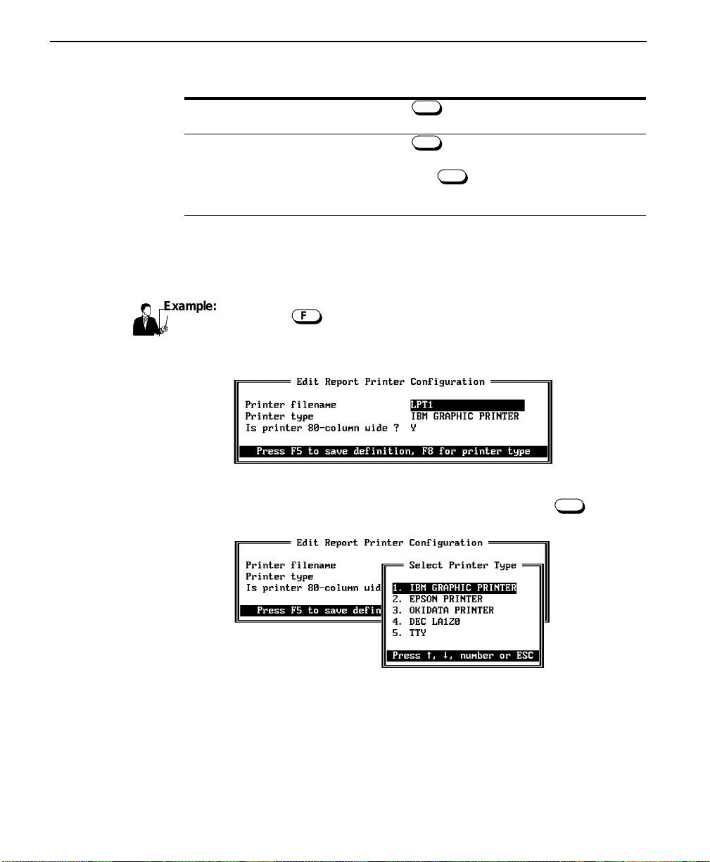
Using Access Manager
Example:
Key Meaning Definition
<F9> Log off
<F10> Shut down
Pressing logs you off Access Manager without
shutting it down.
Pressing exits you from Access Manager to
DOS. You must have a LEVEL4 access to do this.
After pressing , a message appears that asks
you whether or not to shut Access Manager down.
Typing Y continues the shut-down.
When Access Manager is started in VT100 mode, the bottom of the
screen displays escape key sequences instead of function keys. However,
if you are using the PC keyboard (rather than a terminal keyboard), the
function keys must still be used.
Using the function key:
F8
You are in th e Printer filename field, and you’d like to know
what other
printer options are available.
F9
F10
F10
3-8
T o fi nd out what other p rinter options are av a ilable, pr ess . A screen
containing a list of options appears, superimposed, over the first screen.
Cursor movement keys
The following keys are also referred to as directional keys throughout the
Access Manager manual. They are used to move between fields, entries,
and screens.
Access Manager 2000 User Manual
F8
Page 75

A listing of these definitions is provided in Table 3-2, “Cursor movement
key definitions in PC mode,” o n page 3 -9.
Table 3-2 Cursor movement key definitions in PC mode
Key Meaning Definition
Basics
<Up Arrow> and
<Down Arrow>
<Left Arrow> and
<Right Arrow>
<PgDn>:
<PgUp>
<Home>
<End>
These keys move the cursor up or down to position the
cursor at an entry (or item) from a list on the screen.
• If a list extends beyond the top or bottom of the
current screen, the screen scrolls in the direction of
the pressed arrow key.
• On single-screen displays, the cursor wraps around
to the opposite end of the screen.
These keys move the cursor to the left or right on a data
entry line.
Next Page If more than one screen of information exists for the
Previou
Page
current screen, pressing displays the next
screen (page) of information below the current cursor
position.
If an additional screen of information exists above the
current screen (page), pressing displays the
next screen of information above the current cursor
position.
Pressing moves the cursor to the beginning of a
list. This includes lists which have more items than can
be displayed in a single screen.
Pressing moves the cursor to the end of a list.
This includes lists which have more items than can be
displayed in a single screen.
Home
End
PgDn
PgUp
Special keys
The keys described in this section are used to perform special functions
within Access Manager.
A listing of these definitions is provided in Table 3-3, “Special key
definitions in PC mode,” on page 3 -10.
Access Manager 2000 User Manual
3-9
Page 76

Using Access Manager
Enter
Ctrl
PgDn
Ctrl
PgUp
Ctrl
Ctrl
T able 3-3 Special key definitions in PC mode
Key
<ENTER>
The following four choices require the key to be pressed and held while pressing the
second key. The key is displayed on the
screens as (^).
<Ctrl>-<PgDn>
<Ctrl>-<PgUp>
<Ctrl>-<Left
Ctrl
Next Element Press the key combination to select the
Previou
Element
Near End Press the key combination from the On-
Arrow>
<Ctrl>-<Right
Far End Press the key combination from the On-
Arrow>
<ESCAPE>
Pressing the key either selects the option
highlighted by the current cursor position from a menu
screen, or accepts the value of data entered into a
selected field. If less than the maximum number of
characters are entered in a field, press t
complete the entry for that line a nd move the highlight to
the next line.
Ctrl
Function Key Definition
next circuit element in a selected range. This key name
appears on the screen as <Ctrl>-<PgDn>.
Press the key combination to select the
previous circuit element in the selected range. This key
name appears on the screen as <Ctrl>-<PgUp>.
line screens to select the near-end CSU information.
This key name appears on the screen as <Ctrl>-<Right
Arrow> Near-end.
line screens to select the far-end CSU information. This
key name appears on the screen as <Ctrl>-<Right
Arrow> Far-end.
Press the key to cancel data input requests on
an operational basis and to exit an option menu without
selecting an option. Also press to immediately
abort a connection request or print request.
Esc
screen and many othe
Enter
Esc
3-10
Access Manager 2000 User Manual
Page 77

Key
Backspace
Basics
<INS>
<DEL>
<BACKSPACE>
Equivalent VT100 Keystroke
With Access Manager operating in the VT mode under pcANYWHERE
III, commands entered from the VT100 terminal use different keystroke
combinations than the PC keyboard. This occurs because the VT100
terminal, unlike the PC, does not have function keys.
Press from a data entry screen to toggle
Ins
between the text insert mode and the text overwrite
(normal) mode. When the insert mode is activated, a
block cursor blinks in the input line. In the overwrite
mode, a smaller cursor blinks at the bottom of the input
line. The insert mode is active for the current lin e only. If
you move the cursor up or down one line with the arrow
keys, or if you press to save the screen values,
the insert mode goes back to the overwrite mode.
When you are in the overwrite mode on any screen,
entering any character in the first position of the data
entry line deletes all other characters on that line. To
change only the first character in a line, press to
change from the overwrite mode to the insert mode. If
all character positions allowed for a data entry line are
filled, delete the first character with the key and
enter the new first character.
Press to delete the character or space at the
Del
current cursor position.
Press the key to delete the character or
space immediately preceding the current cursor
position.
F5
Ins
Del
In the VT terminal mode, the screen displays the applicable escape key
combinations used with the VT100 terminal.
The PC function keys and their corresponding VT100 escape sequences
are listed in Tabl e3-4, “Fun ction key and escape key sequences in VT100
terminal mode,” on page 3 -12. This table also describes the function of
each sequence.
To return to the regular operating mode, shut down Access Manager and
restart it without the /VT command.
Access Manager 2000 User Manual
3-11
Page 78

Using Access Manager
Table 3-4 Function key and escape key sequences in VT100 terminal mode
PC mode
Function Key
<Esc> <Esc>-<Esc> Cancel data/Exit request
<Up Arrow> <Esc>-<U> Move one line u
<Down Arrow> <Esc>-<D> Move one line down
<Left Arrow> <Esc>-<L> Move cursor left
<Right Arrow> <Esc>-<R> Move cursor right
<Home> <Esc>-<H> Move cursor to first line
<End> <Esc>-<E> Move cursor to last line
<PgUp> <Esc>-<P> Move to previous page
<PgDn> <Esc>-<N> Move to next page
<Ctrl>-<Left Arrow> <Esc>-<C> -<L> S elect Far-End
<Ctrl>-<Right Arrow> <Esc>-<C>-<R> Select Near-End
<Ctrl>-<PgUp> <Esc>-<C>-<P> Select Previous CSU
<Ctrl>-<PgDn> <Esc>-<C>-<N> Select Next CSU
<Ins> <Ins> Toggle insert/overwrite
<Del> <Del> Delete character/space
<F1> <Esc>-<1> Help
<F2> <Esc>-<2> Go to previou s screen
<F3> <Esc>-<3> Return to Main Menu
<F4> <Esc>-<4> Tog gle between manual and automatic
<F5> <Esc>-<5> Accept updated info to element
<F6> <Esc>-<6> Accept updated info to range of
<F7> <Esc>-<7> Toggle status of data monitor
<F8> <Esc>-<8> Show a list of options
<F9> <Esc>-<9> Log off Access Manager without
<F10> <Esc>-<10> Shut down Access Manager with
not available <Esc>-<C>-<S> Update
VT100 terminal mode
Escape key sequence Description
alarm acknowledge modes
element
shuttin g down
LEVEL4 access onl
pcANYWHERE
.
Screen
Help
3-12
To get a help screen that provides function k ey definitions,
press .
Access Manager 2000 User Manual
F1
Page 79

Basics
This displays an on-line help screen labeled Function Key
Definitions. This is shown in Table 3-5, “On-line Help screen (host
PC mode)”.
Figure 3-5 On-line Help screen (host PC mode)
Error Messages
The screen will be appropriate for the terminal mode (PC or VT100) you
are currently in.
If you need technical help, refer to this manual or call Verilink Technical
Support at 1-408-945-1199.
If you enter an unacceptable value in a data entry screen, an error
message will appear in the middle of your screen. If you’re using a color
monitor, the error message will be white text in a red box. The word
“ERROR” will appear at the top. This is followed by information which
tells you which field and option is causing the error. It may point out the
appropriate range of values or necessary corrective action.
Access Manager 2000 User Manual
3-13
Page 80

Using Access Manager
Warning Messages
If you’re using a color monitor, the warning message will be white text in
a red box. The word “WA RNING” will appear at the top.
You will receive a warning message when you’re about to perform an
operation which may cause a line to become out of service or database
information to be overwritten.
Warning messages always offer you a choice. They allow you to choose
whether you want to continue the operation or take the often wiser course
of backing out.
Alarm Messages
a red box. The word “ALARM” will appear at the top.
Alarm messages provide information about the state of either Verilink
equipment or the transmission lines. A concurrent alarm record is
generated and deposited into the database.
Getting started with Access Manager
This section tells you about:
■ Starting the On-Site Access Manager (pag e3-14)
■ Logging on (page 3-16)
■ Entering information into the screens (pag e3-18)
■ Making a selection (pag e3-18)
■ Exiting Access Manager (pag e3-19)
■ Logging off (pag e3-19)
If you’re using a color monitor, the warning message will be white text in
S tarting the
On-Site Access
Manager
If you modified your AUTOEXEC.BAT file appropriately after you
installed Access Manager, then Access Manager---and any associated
programs---will start automatically when you power up your host PC.
If you didn’t, then either:
3-14
■ modify your AUTOEXEC.BAT file, as explained in “Creating a
batch file for automatic start-up” on page 2 -9, or
Access Manager 2000 User Manual
Page 81

Getting started with Access Manager
■ follow the procedure to manually start Access Manager:
To manually start Access Manager:
1. Turn on and boot up your computer so that the operating system
prompt (usually C:>) app ears o n the screen.
2. Type CD AM2000 (or the name you assigned the directory where
you installed Access Manager). Press .
Enter
3. If you are using pcANYWHERE III, type
AN YWHEREAUTOMATIC.
Press to load the program.
Enter
4. To start Access Manager, use one of the following commands:
If you are using a Type:
color monitor with a color adapter card
monochrome monitor with a monochrome adapter
card
monochrome monitor with a color adapter card
AM2000
AM2000/BW
AM2000/BW
After Access Manager is started, the AM2000 Username screen
appears and prompts you to enter a user name to log into Access
Manager.
Access Manager
serial numbe
input screen for user name
Access Manager 2000 User Manual
3-15
Page 82

Using Access Manager
Enter
When Access Manager is shipped from Verilink, the database has
only one user name defined---LEVEL4. LEVEL4 has an access
level of four.
5. Now you’re ready to log on.
Logging on
To log on:
1. At the AM2000 User name screen, you need to enter a user name. If
you still haven’t typed a valid user name after three attempts, Access
Manager exits to DOS.
• If you are logging on to Access Manager for the first time, type
LEVEL4 and press .
• If your system administrator has already set up user definitions
in Access Manager, type your user name (up to 28 characters)
and press .
Enter
After Access Manager accepts your user name, a password entry
screen appears.
2. Type your password and press .
The password is hidde n while you type it in. You have three cha nces
to enter it correctly before Access Manager returns you to the
Username screen.
Enter
3-16
• If you are logging onto Access Manager for the first time, type
TEST (the default password for user name LEVEL4).
Access Manager 2000 User Manual
Page 83

Getting started with Access Manager
After the user password is accepted, the Main Menu appears.
3. You can now perform Access Manager operations as outlined in the
chapters that follow.
4. If this is the first time Access Manager is started, enter the time and
date (See Chapter 4, Configuring Ac c ess Manager for more
information about the date and time menus).
5. Th is p rocedure is now completed.
S tarting the
To manually start Access Manager from a remote VT100 terminal (or
equivalent emulation):
Remote Access
Manager
2. Type CD AM2000 (or the name you assigned the directory where
3. If you are using pcANYWHERE III, type ANYWHERE
4. If you are using pcANYWHERE to control Access Manager from a
1. Turn on and boot up your computer so that the operating system
prompt (usually C:>) app ears o n the screen.
you installed Access Manager). Press .
AUTOMATIC. Press to load the program.
Enter
Enter
remote VT100 terminal (or equivalent emulation), type
AM2000/BW/VT and press .
Note:
The /BW command may be optional for your setup. Refer to
Enter
“Creating a batch file for automatic start-up” on p age2-9, for
detailed information on the /BW command.
When Access Manager is started in the VT100 mode, the bottom of
the screen displays escape key sequences instead of function keys.
Access Manager 2000 User Manual
3-17
Page 84

Using Access Manager
Note:
5. After Access Manager is started, the AM2000 Startup Screen
Making a selection
Entering
information into
the screens
All menu selections can be made by pressing the or keys to
highlight the desired option and then pressing to select that
option.
You can also select a menu option by typing the first character of that
option, unless there are multiple options with the same first character.
When multiple menu options appear with the same first character and you
type that character, Access Manager always chooses the first option.
If an option is numbered, then typing that number will also select that
option.
Data entry fields are characterized by the type and maximum number of
characters they accept. When the maximum number of characters is
reached, the field is filled, the data is accepted, and the highlight moves to
the next field.
When Access Manager is started in the VT100 mode, the bottom
of the screen displays escape key sequences instead of function
keys.
appears and prompts you to enter a user name to log into Access
Manager. Figure 3 -1, “Username Screen,” on page 3-2 shows this
screen.
Enter
3-18
If an invalid character type is entered in a field, the system beeps. This
occurs, for example, if you try to enter an alphabetic character in an allnumeric f iel d, such a s a n ode num ber. The sy ste m als o b eeps i f you are in
the insert mode and the field is already full.
Note:
The and keys may be used to move between lines from any
character position. The cursor a lways positions itself to the left of th e first
character in the line selected.
Access Manager 2000 User Manual
Typed spaces at the end of a field are treated by Access Manager
as entered characters. Blanks at the end of a field may cause the
system to beep. If this occurs, place the cursor after the last
visible character and press to delete spaces.
Page 85

Getting started with Access Manager
Any valid alphanumeric characters or symbols, including spaces, are
valid in an alphanumeric field. A DOS filename is defined by any valid
DOS character and filename.
Logging off
Access Manager
serial numbe
input screen for user name
Exiting Access
Manager
To log off Access Manager:
Press . You will ber returned to the AM2000 Username screen.
You cannot shut down Access Manager unless you are logged in with
access at LEVEL4.
To shut down Access Manager:
F9
1. Press from any place in the program except when a screen
F10
requests any key as a response. A warning message now appears.
2. To halt Access Manager and return to DOS, type Y. Any other
response returns you to the Main Menu.
CAUTION
F10
!
The key must be used to exit from Access Manager. Do not
shut down Access Manager by rebooti ng the computer; Doing so
may corrupt the database.
Access Manager 2000 User Manual
3-19
Page 86

Using Access Manager
3-20
Access Manager 2000 User Manual
Page 87

Chapter
4
Configuring Access Manager
This chapter provides instructions for setting up Access Manager 2000.
These operations are performed from the Utilities option of the
Main Menu.
Configuration procedure overview
Configuration
tasks
The tasks outlined in this chapter include:
■ Setting the date and time (page 4-2)
■ Configuring the site (pag e4-3)
■ Updating us er definitions (pag e4-23)
■ Reviewing and archiving events logs (page 4-28)
■ Downloading firmware to the nodes (pag e4-33)
Utilities Menu
To access the Utilities Menu:
■ Select the Utilities option from the Main Menu by
highlighting the option and pressing , or by typing U. The
Utilities Menu appears.
Access Manager 2000 User Manual
Enter
4-1
Page 88

Configuring Access Manager
Setting the date and time
Access Manager uses DOS commands to update the system clock. On
some computers, these DOS commands also update the hardware realtime clock.
■ If your system does not update the hardware clock through DOS
commands, then you may have problems if your system is rebooted
either deliberately or due to power loss.
Therefore, to insure that your system clock remains correct, exit
Access Manager and use the commands or utilities supplied with
your computer to update the hardware clock.
■ If your system has an accurate real-time clock, you probably don’t
need to set the date and time.
■ If your system does not have a real-time clock and you did not set
the time and date when you booted your system, the time and date
may not be correct. Setting the time and date in this menu also sets
the DOS time and date.
To set the date and time
1. From the Utilities Menu, select Date/Time. The Set Time & Date
screen appears.
2. Enter the correct date and time.
• To save the changes and set the system clock, press .
• If you do not want to set the system clock, press to return
to the Utilities Menu.
3. The procedure is complete.
4-2
Access Manager 2000 User Manual
F5
F2
Page 89

Configuring the site
Configuring the site
Configuring the site includes the following activities:
■ Differentiating the site (pag e4-3)
■ Configur ing the report printer (pag e4-5)
■ Configur ing the on-line data pri nt e r (page 4-8)
■ Specifying the alarm destination (page 4-8)
■ Setting the performance data polling hour (page 4-11)
■ Assigning database allocations (page 4-12)
■ Assigning comline definitions (page 4-14)
T o confi gure the site, you’ll need to access the Installation Menu fro m the
Utilities Menu.
■ From the Utilities menu, select Installation. The Installation
Menu will appear.
Differentiating the
site
To differentiate the site, you need to assign the node a site name and a
manager type.
The site name that you assign during this procedure will subsequently
appear in the upper left corner of the monitor screen. Until you define the
site name, the words NOT YET DEFINED will display on the monitor
screen.
Access Manager 2000 User Manual
4-3
Page 90

Configuring Access Manager
When a number of Access Managers have access to a given node, the
node needs to know “who it’s talking to”. To do this, you need to identify
each Access Manager by assigning it a Manager Type.
An Access Manager can be assigned one of three Manager Types:
PRIMAR , SECONDAR , or TECHNICIAN.
■ You wo uld assi gn the types, PRIMARY and SECONDAR , to the two
Access Managers which are to receive alarms.
■ You would assign the Manager Type, TECHNICIAN, to an
Access Manager that is not designated as one of the alternate alarm
paths and is dialing in only
to do diagnostics or troubleshooting
from a remote location.
When a node controller sends an alarm to a PRIMARY or SECONDARY
Manager Type, it subsequently deletes the alarm from its buffer. When
a node controller sends an alarm to a TECHNICIAN Manager Type,
it retains the alarm in its buffer until the diagnostics session is over and it
has been able to send the alarm to the PRIMARY and/or SECONDARY
Access Manager.
To differentiate the site:
1. From the Main Menu, go to the Utilities Menu.
2. From the Utilities Menu, select the Installation option.
3. From the subsequent screen, select the Site option. The
following screen will appear.
You’ll need to assign a Site Name and Manager Type.
Until you assign the site name, the site name displays as NOT YET
DEFINED in the Edit Site Name screen.
4. Type in the name you want to assign to your site. This name can be
up to 20 characters long.
4-4
Access Manager 2000 User Manual
Page 91

Configuring the site
5. To see what Manager Type options are available, press .
F8
The following screen will appear.
6. Assign a Manager Type to your Access Manager.
• To save the site information
, press . The site name will
F5
subsequently appear in the upper left corner of the screen.
• If you don’t want to change the site information
, press to
F2
return to the Installation Menu.
7. Your task is complete.
The report printer is the printer that prints the performance data analysis
Configuring the
report printer
and bar charts from information in the database. Database information
can be viewed from the Database Access Menu.
T o configure the report printer:
■ From the Installation Menu, select Report. The screen labeled
Edit Report Printer Configuration now appears.
Access Manager 2000 User Manual
4-5
Page 92

Configuring Access Manager
Report output destination
The Printer Filename option specifies a destination for the report
output. You can print to either:
■ a parallel port (LPT1 or LPT2), or
■ a disk file
You must use the DOS fi le naming convention to enter a file name or a
full path name for a disk file. The Printer Filename field allows
you to enter up to 20 characters: 8 characters for the file’s name and the
remaining 12 characters for the path. If the file name were PRINT1.DOC
and the path were C:\AM2000\, the entire filename would be
C:\AM2000\PRINT1.DOC.
You should include the full DOS path
■ If a non-reserved name is specified, the report is saved to a disk file
even though it is not required.
and may be accessed later.
■ If a full DOS path is not included, the file is placed in the current
directory.
■ If a filename is specified and you press to save the definition,
F5
a file is created on disk with the name specified and zero bytes
assigned. This is done to verify that the definition is correct and the
file can be created.
■ If the filename NUL or NONE is used, the output is disc arded.
■ If no printer is to be attached, then NONE should be entered to
avoid the PC attempting to print to a non-existent printer and
“freezing” in the process.
Enter a filename and press .
Enter
Printer Type
Printer Type selects the type of printer used to print the data. This
field is only valid when LPT1 or LPT2 is entered for the Printer
Filename option.
Access Manager supplies drivers for five printers, but only one of the
predefined printer types can be entered in this field at a time.
4-6
The only difference in the five printer types supported is in the characters
used to program the printers for condensed (compressed) mode and to
Access Manager 2000 User Manual
Page 93

Configuring the site
restore them to normal mode (10 cpi). The hexadecimal values used for
the printer types are listed as follows:
Printer Type Condensed Nor mal
IBM Graphic
Epson
Okidata
DEC LA120
TTY
These are for the 320/321 family of printers.
The 190 family of printers use the values shown for the IBM or
Epson printers and, therefore, should be installed as an IBM or
Epson.
1B, 5B, 34, 77 (ESC 4w 1B, 5B, 30, 77 (E SC0w)
The TTY option is for printers that are unable to print
compressed characters.
Also, select TTY for a printer not listed or whose compressed
character commands do not match any of those listed in the
options table. Compressed characters are not used.
0F 12
0F 12
1D 1E
1. With the cursor positioned on the Printer Type optio n, press
F8
to display a window of the predefined printer types.
A screen labeled Select Printer Type appears on top of
the Edit Report Printer Configuration screen.
2. Place the cursor on the desired choice, and press or press
Enter
the selection number.
If you use a name other than LPT1 or LPT2 and then press
F5
to save the options, NOT APPLICABLE will appear in the
Printer Type field.
Access Manager 2000 User Manual
4-7
Page 94

Configuring Access Manager
F5
Configuring the
on-line data printer
Is Printer 80-Column Wide?
The Is Printer 80-Column Wide? data entry field appears in
the Edit Report Printer Configuration screen. If you
enter Y, the type may be compressed to print 132 columns on 8.5-inch
paper, if supported by the printer type. Only those reports over 80
columns wide are compressed. Otherwise, the printer is set for 80
columns only. The number of lines is always 66.
When you are satisfied with the menu options and want to save them and
exit from the Installation Menu, press . Or, press to exit this
F5 F2
menu without saving the changes. Records beyond the quota are deleted
from the database when the key is pressed.
The on-line printer is the printer that prints the performance analysis and
bar charts from information in the elements (cards) themselves. This
information can be viewed from in the On-line Access Menu.
To configure the report printer:
■ From the Installation Menu select On-line. The Edit On-line
Printer Configuration screen appears.
Specifying the
alarm destination
4-8
This screen defines where the on-line information is printed and what
type of printer is used. The selections and menu are the same as in the
Edit Report Printer option described in the previous section.
Refer to that section for an explanation of the menus and choices.
You can specify whether alarm reports go to a printer, file, or a computer.
This is done through the Edit Alarm Destination screen.
Access Manager 2000 User Manual
Page 95

Configuring the site
To select where you want the alarms to go:
■ From the Installation Menu, select Alarm. The Edit Alarm
Destination screen will appear.
Sending alarms to a printer or file
To output the alarm report to a printer or to a file:
■ Follow the same rules for Alarm Printer Filename and
Alarm Printer Type as you did for Printer Filename
and Printer Type in “Configuring the report printer” on
page 4-5, earlier in this chapter.
!
Sending alarms to a computer
You can choose to output alarm messages to another computer, such as
one running Accumaster.
Before attempting to configure Access Manager to send alarm reports to
another compute , you must first enter SERIAL DEVICE for the
Access Arrangement of a Comline in the Comlines Definition
screen. In other words, the only time you can use COMx (where x is a
number) in the Alarm Printer Filename field is when you have
defined the comline for a serial device
.
CAUTION
However, if you’re using an actual serial printer, you cannot use a
name such as
do, Access Manager may halt. Instead, you must enter LPT1 or LPT2
Edit Report Printer Configuration
in the
MODE command from DOS to redirect the LPT por t to a non-
COM1
Alarm Printer Filename
in the
screen, and then use the
Access Manager 2000 User Manual
field. If you
4-9
Page 96

Configuring Access Manager
Digiboard COM port. Refer to the DOS manual for proper use of the
MODE command. Do not duplicate filenames listed in Table 2-1,
“Access Manager Installation Files,” on page 2-4.
To output alarm messages to another computer:
1. In the Alarm Printer Filename field, enter the comline
name.
2. Leave the Printer Type field blank. It is not applicable.
Alarm Channel Protocol
The Alarm Channel Protocol data entry field appears in the
Editing the Alarm Destination screen. The Alarm Channel
Protocol option is selected by moving the cursor to that line and
pressing to bring up the selection Alarm Channel
F8
Protocol screen.
4-10
If you are using a serial or parallel print e
MESSAGE option. This sends the entire alarm information in ASCII
format. The alarms are printed one alarm message per line.
If you are outputting to a serial port or disk file
MESSAGE option. This sends information in the following formats:
■ the date, time, and node name al arm output in an ASCII format, and
■ the alarm status in an ASCII-formatted hexadecimal format.
Access Manager 2000 User Manual
, select the PLAIN ENGLISH
, select the TERSE
Do not use this option with a serial or parallel printer.
Page 97

Configuring the site
Note:
If your Acc ess Manager includes Accumaster protocol compatibilit
Edit Alarm Destination screen includes a third option,
Accumaster Protocol. If Accumaster Protocol is selecte d,
the alarms are sent to the Accumaster system. This protocol uses flow
control to hold off sending data to Accumaster when requested by
Accumaster. If the connection to Accumaster is disconnected, alarms are
stored in the Access Manager 2000 database until the Accumaster
connection is re-established, at which time all uncleared alarms are sent
to Accumast er.
Note:
Except when the Accumaster Protocol is chosen, the port sending alarm
messages does not use communication flow control or handshaking.
Alarm acknowledgement: Manual or automatic?
The Acknowledge Alarm Automatically? data entry field
appears in the Editing the Alarm Destination screen. This option specifies
the default setting for the alarm status shown at the top of the screen when
a user logs onto Access Manager. To select the automatic mode, type Y.
Refer to Appendix C, "Alarm Report Record Format", for a
description of the alarm printout format.
, the
The Accumaster Protocol option is available only in the Access
Manager -1 000 package.
S etting the
performance data
polling hour
Once you are logged on, press to toggle between the manual and
automatic modes. In the automatic mode, when an alarm occurs, you
briefly see the alarm processing message.
Access Manager collects DS1 performance data every 12 hours and
discards duplicate data collected during any 24-hour period. It polls all
equipped nodes at the same hour in alphanumeric orde r. If the connection
to a node fails, polling for that node is rescheduled up to three times after
all other nodes are polled, for a total of four polling attempts.
Access Manager collects data only from CSUs that meet certain
conditions:
a. The CSUs must be configured as Installed and
Operational.
F4
Access Manager 2000 User Manual
4-11
Page 98

Configuring Access Manager
b. The CSUs must have collection of performance data enabled.
c. The parent nodes of the CSUs must be configured as
Installed and Operational.
For circuit elements accessed through the 4-kbps ESF Data Link, a ci rcuit
must be built between the near and far circuit elements in order to collect
far-end data. This is because all data is stored under the circuit element’s
parent n ode n am e .
Note:
To retrieve data from a far-end CSU, the near-end CSU must be
set to retrieve data.
You must specify the hour when the 12-hour polling cycle for collection
of performance data is initiated.
To specify the polling hour:
1. From the Installation screen, select Hou . The Edit Poll Hour
screen appears.
2. Choose one of the following options:
• To specify the polling hou
, enter a value from 1 to 12 for the
polling hour from 1 to 12, an d press to save the value.
• To disable performance data polling
equal to or greater than 13.
F5
, enter ZERO or a number
Assigning
database
allocations
4-12
Access Manager 2000 User Manual
• To exit from this option without saving changes
, press .
F2
The Access Manager database provides space for the event log, ala rm log,
and performance database (that is, log). You may allocate how much
space is given to each log.
The default allocations, at time of shipment, are shown in Table 4-1,
“Database allocation at time of shipment,” on page 4 -13.
Page 99

T able 4-1 Database allocation at tim e of shipment
Configuring the site
You can
edit these
fields
Type of record
Event 5,000 58 bytes
Alarm 10,000 62 bytes
Performance (3 kinds)
• data (also known as user
• additional 50,000 150bytes
• dtev (also known as EQP
records) 50,000 150bytes
records) 50,000 150bytes
Number or records
per log (default)
Maxi mum size
of record
Each of the three categories of performance records can be edited
separately.
To assign database allocations:
1. From the Installation screen, select Quotas. The screen labeled
Edit Database Record Quotas now appears.
Tells you which network
manager package you have:
AM2000-8
AM2000-24
AM2000-1000
The Edit Database Record Quotas screen also di splays, but d oes not
permit you to change the following:
• The current number of records of each type in use (that is, stored
in the database)
Access Manager 2000 User Manual
4-13
Page 100

Configuring Access Manager
• The current number of installed CSU circuit elements (that is,
configured in the database as Installed and
Operational)
• The maximum number of CSU circuit elements which your
Access Manager Package permits to be installed. If there is no
restriction in the package, this is shown as UNRESTRICTED.
The type of Access Manager package you have is shown last. This
can be AM2000-8, AM2000-24, or AM2000-1000.
When the current number of records reaches the maximum allowed,
no new records will be added. You may increase the maximum
number of records allowed to prevent loss of data, or you may
choose to take some time to archive or delete the older data.
2. Adjust the maximum allowable record numbers as needed.
3. Select one of the following actions:
• To save the changes made
, press . The changes are saved,
F5
and the current records used counts are updated.
• To exit the menu without saving the changes
, press .
F2
4. If you do not increase the all ocations, you may reduce the records in
use by saving them to another file using the Archive function.
A comline, or communication line, is a serial port on your computer. It is
Assigning comline
definitions
used to transmit to or receive data from a network node or another
computer through an Electronic Industries Association (EIA) standard
RS232 interface.
When you assign a comline definition, you specify what protocol, or
“language”, the port will be using to communicate with any device
connected to it.
4-14
Access Manager 2000 User Manual
 Loading...