

Page 1

MultiPro
Verilink Corporation
127 Jetplex Circle
Madison, AL 35758
1.800.VERILINK
Platform
Series
i
34-00271
September 1998
Page 2

ii
✍
Copyright
Documentation
Disclaimer
Trademarks
©1998 TXPORT. All rights reserved. No part of this publication may be reproduced, transmitted, transcribed, stored in a retrieval system, or translated into any language in any form by any means without
the written permission of TXPORT.
Reorder # 34-00271
rd
Edition, September 1998
3
TXPORT shall not be liable f or errors con tained herein or for incident al or consequ ential damages in
connection with the furnishing, performance, or use of this material. TXPORT reserves the right to
revise this publication from time to time and make changes in content without obligation to notify any
person of such revision changes.
Contents of this publication may be preliminary and/or may be changed at any time without notice and
shall not be regarded as a warranty.
TXPORT makes no representation or warranties of any kind whatsoever with respect to the contents
hereof and specifically disclaims any implied warranties of merchantability or fitness for any particular
purpose.
NetWare and Novell are registered trademarks of Novell, Inc.
Xerox is a registered trademark of Xerox Corporation.
NCR is a registered trademark of National Cash Register Corporation
Sperry is a registered trademark of Sperry Rand Corporation.
Uniscope is a registered trademark registered by Sperry Rand Corporation and owned by Unisys.
Windows is registered trademark of Microsoft Corporation.
AppleTalk is a registered trademark of Apple Computer, Inc.
OpenView is a registered trademark of Hewlett-Packard Company.
CROSSTALK is a registered trademark of Attachmate Corporation.
PROCOMM is a registered trademark of DATASTORM TECHNOLOGIES, INC.
Any other named products herein are trademarks of their respective companies.
Acknowledgment
The software used in the SNMP function of this product contains material derived from the following
source:
Copyright © 1989 by the Regents of the University of California. All rights reserved.
Redistributions in binary form must reproduce the above copyright notice, this list of conditions, and
the following disclaimer in the documentation and /or other materials provided with the distribution.
All advertising materials mentioning features or use of this software must display the following
acknowledgment:
This product includes software developed by the University of California, Berkeley and its contributors.
Neither the name of the University nor the names of its contributors may be used to endorse or
promote products derived from this software without specific prior written permission.
This software is provided by the regents and contributors ‘as is’ and any express or implied warranties,
including, but not limited to, the implied warranties of merchantability and fitness for a particular purpose are disclaimed. In no event shall the regents or contributors be liable for any direct, indirect, incidental, special, exemplary, or consequ ential damages (including, but not limited to, procurement of
substitute goods or serv ices; loss of use, data, or profits; or business interrupt ion) however caused and
on any theory of liability, whether in contract, strict liability, or tort (including negligence or otherwise)
arising in any way out of the use of this softw are , even if advised of the possibility of such damage .
Page 3

FCC Requirements
iii
FCC Requirements
This equipment (9000, 9101, 9111 , and 9211) has been te sted and found to comply with the limits for a
Class A digital device, pursuant to Part 15 of FCC Rules. These limits are designed to provide reasonable protection against harmfu l interference when the equi pment is operated in a commercial environment. This equipment ge nerates, uses, and can radiate radio frequency energy and if no t installed and
used in accordance with the instruction manual, may cause harmful interference to radio communications. Operation of this equipment in a residential area is likely to cause harmful interference in which
case the user is req uired to correct the interfe rence at his own expense. Th is device must also accept
any interference received, including i nterference tha t may cause unde sired operation. Shielded cables
must be used to ensure compliance with the Class A FCC limits.
Changes or modifications to this unit not expressly approved by the party responsible for
compliance could void the user’s authority to operate the equipment.
This equipment complies with Part 68 of the FCC Rules. On the rear or bottom of the unit is a label
that contains the FCC registration number and other information. If requested, provide this information
to the telephone company.
All direct connections to the network lines must be made using stan dard plugs and jacks (co mpliant
1
with Part 68). The tables below present a list of applicable registration jack USOCs, facility interface
codes (FICs), and service order codes (SOCs). These are req uired to order service from the telco.
9101
Port ID REN/SOC FIC USOC
56 kbps 6.0F 04DU5 - 56 RJ-48S jack
9111 Port 1 T1 Option
Port ID REN/SOC FIC USOC
1.544 Mbps SF
1.544 Mbps SF, B8ZS
1.544 Mbps ANSI ESF
1.544 Mbps ANSI ESF, B8ZS
6.0N 04DU9-BN
RJ-48C jack
04DU9-DN
04DU9-1KN
04DU9-1SN
9111 Port 1 DDS Option
Port ID REN/SOC FIC USOC
56 kbps 6.0F 04DU5-56 RJ-48S jack
If the unit appears to be malfunctioning, it should be disconnected from the network lines until the
2
source of trouble is deter mined to be your equip ment or the telephon e line. If your equipme nt needs
repair, it should not be reconnected until it is repaired.
The unit has been designed to prevent harm to the network. If the telephone company finds that the
3
equipment is exceeding tolerable parame ters, it can tempo rarily disconnec t service. In this case, the
telephone company will give you advance notice, if possible.
No customer is authorized to repair this equipment, regardless of warranty status.
4
If the telephone company alters its equipment in a manner that will affect the use of this device, it
5
must give you warning so that you have the opportunit y for uninterrupt ed service. You will be
advised of your right to file a complaint with the FCC.
In the event of equipment malfunction, all repairs should be performed by our company or an
6
authorized agent. It is the responsibility of users requiring service to report the need for service to our
company or to one of our authorized agen ts.
The affadavit at the end manu al must be co mpleted by the installer.
7
Page 4

iv
Canadian
Emissions
Requirements
Warranty
This digital apparatus does n ot exceed the Class A li mits for radi o nois e emis sions from di gi tal app aratus set out in the Radio Interference Regulations of the Canadian Department of Communications.
Le présent appare il numérique n’émet pas de brui ts radioélect riques dépassant les limites appl icables
aux appareils numérique s (de la clas s A) pres crites dan s le Règl ement sur le b rouillag e radio électriqu e
édicté par le mini stère des Communications du Canada.
Notice: The Industry Canada label identifies certified equipment. This certification means that the
equipment meets certain tel ecommunications network p rotective, operational and safety requirement s.
The Industry Canada does not guarantee the equipment will operate to the user’s satisfaction.
Before installing this equipment, users should ensure that it is permissible to be connected to the facilities of the local teleco mmunications company. The equipment must also be installed using an acceptable method of connection. In some cases, the company’s inside wiring associated with a single lin e
individual service may be extend ed by means of a certified connector assemb ly (telephone extension
cord). The customer should be aware that co mpliance with the above conditions may not p r event degradation of service in some situations.
Repairs to certified equipment should be made by an authorized Canadian maintenance facility designated by the supplier. Any repairs or alterations made by the user to this equipment, or equipment malfunctions, may give the telecommunications company cause to request the user to disconnect the
equipment.
Users should ensure for their own protection that the electrical ground connections of the power utility,
telephone lines and internal metallic water pipe system, if present, are connected together. This precaution may be particularly important in rural areas.
Caution: Users should not attempt to make such connections themselves, but should contact the appropriate electric inspection authority, or electrician, as appropriate.
TXPORT warrants each unit against d efects in material and work manship for a period of five years
from the date the unit was shipped to the customer. If the unit malfunctions at any time during the warranty period, TX PORT will repair, or at TXPORT’s option, replace the unit free of charge.
The remedies listed herein are the users sole and exclusive remedies. TXPORT shall not be liable for
any indirect, direct, incidental or consequential damages. The owner must return the unit to the factory,
shipping prepaid and pa ckaged to the best commercial standard fo r electronic equipment. TXPORT
will pay shipping charges for delivery on return. The customer is responsible for mode and cost of
shipment to TXPORT. This warranty does not apply if the unit has been damaged by accident, misuse
or as a result of service o r modification by other than TXP O RT personnel.
Hardware
Warranty
TXPORT warrants its hardware products to be free from defects in workmanship and materials, under
normal use and service, for five years from the date of purchase from TXPORT or its Authorized
Reseller:
If a product does not operate as warranted above during the applicable warranty perio d, TXPORT shall,
at its option and expens e, repair the defe ctive product or part, d eliver to Customer an equivalent product or part to replace the defective item, or refund to Customer the purchase price paid for the defective
product. All products that are replaced will become th e property of TXPORT. Replacement product s
may be new or reconditioned. Any replaced or repaired prod uct or part has a n inety (90) d ay warranty
or the remainder of the initial warranty period, whichever is longer.
TXPORT shall not be responsible for any software, firmware, information, or memory data of Customer contained in, stored on, or integrated with any products returned to TXPORT for repair, whether
under warranty or not.
Page 5

Software Warranty
v
Software
War ran ty
Standard
Warranty
Service
Warranties
Exclusive
TXPORT warrants that the software programs licensed from it will perform in substantial conformance
to the program specifications therefor for a period of ninety (90) days from the date of purchase from
TXPORT or its Authorized Reseller. TXPORT warrants the media containing software against failure
during the warran ty period. No updates a re provided. TXPORT's sole obligatio n with respect to this
express warranty shall be ( at TXPORT's discretion) to r efund the purchase p rice pa id by Customer for
any defective software products, or to replace any defective media with software which substantially
conforms to TXPORT's applicable published specifications. Customer assumes responsibility for the
selection of the appr opriate applicat ions program and a ssociated reference materials. TXPORT makes
no warranty or representation that its software products will work in combination with any hardware or
applications software products provided by third parties, that the operation of the software products
will be uninterrupted or error free, or that all defects in the software products will be corrected. For any
third party products listed in the TXPORT software product documentation or specifications as being
compatible, TXPORT will make reasonable efforts to provide compatibility, except where the
non-compatibility is caused by a bug or defect in the third party's product.
Standard warranty ser vice for hardwa re products may be obtained by delivering the d efective product,
accompanied by a copy of the dated proof of purchase, to TXPORT's Corporate Service Center or to an
Authorized TXPORT Service Center during the applicable warranty period. Standard warranty service
for software products may be obtained by telephoning TXPORT's Corporate Service Center or an
Authorized TXPORT Service Center, within the warranty period. Products returned to TXPORT's Corporate Service Center must be pre-authorized by TXPORT with a Return Material Authorization
(RMA) number marked on the outside of the package, and sent pre paid, insured, and packag ed appropriately for safe shipment. The repaired or replaced item will be shipped to Customer, at TXPORT's
expense, not later than thirty (30 ) day s after recei pt of the de fective product by TXPORT.
If a TXPORT product does not operate as warranted above, customer’s sole remedy for breach of that
warranty shall be repair, replacement, or refund of the purchase price paid, at TXPORT’s option. To the
full extent allowed by law, the foregoing warranties and remedies are exclusive and are in lieu of all
other warranties, ter ms, or conditions, express or i mplied, either in fact or by operation of law, statutory
or otherwise, including warranties, terms, or conditions of merchantability, fitness for a particular purpose, and satisfactor y qual ity. TXPORT neither assumes nor authori zes any othe r pers on to assume for
it any other liability in connection with the sale, installation, maintenance or use of its products.
TXPORT shall not be liable under this warranty if its testing and examination disclose that the alleged
defect in the product d oes not exist or was caused by customer’s or any third person’s misuse, neglect,
improper install ation or testing , unauthorized attempts to r epair or modify, or any other ca use beyond
the range of the intended use, or by accident, fire, lightning, or other hazard.
Limitation
of Liability
Governing
Law
To the full extent allowed by law TXPORT also excludes for itself and its suppliers any liability,
whether based in contra ct or tort (includi ng n egligence), for in ciden tal , conse qu ential, indi rect, sp ecial,
or punitive damages of any kind, o r for loss of revenue or profits, loss of busi ness, loss of i nformation
or data, or other financial loss arising out of or in connection with the sale, installation, maintenance,
use, performance, failure, or interruption of its products, even if TXPORT or its authorized reseller has
been advised of the possibility of such damages, and limits its liability to repair, replacement, or refund
of the purchase price paid, at TXPORT’s option. this disclaimer of liability for damages will not be
affected if any remedy pro vi ded here in shall fail of its essential purpo se.
Some countries, states, or provinces do not allow the exclusion or limitation of implied warranties or
the limitation of incidental or consequential dama ges for certain prod ucts supplied to consumers, so the
above limitations and exclusions may be limited in their application to you. This warranty gives you
specific legal rights which may vary depending on local law.
This Limited Warranty shall be governed by the laws of the state of Alabama.
TXPORT,Inc.
, 127 Jetplex Circle, Madison, AL 35758 ( 256) 772-3770
Page 6

vi
Page 7

Table of Contents
Copyright. . . . . . . . . . . . . . . . . . . . . . . . . . . . . . . . . . . ii
Documentation Disclaimer . . . . . . . . . . . . . . . . . . . . . ii
Trademarks . . . . . . . . . . . . . . . . . . . . . . . . . . . . . . . . . ii
Acknowledgment. . . . . . . . . . . . . . . . . . . . . . . . . . . . . ii
FCC Requirements . . . . . . . . . . . . . . . . . . . . . . . . . . .iii
Canadian Emissions Requirements . . . . . . . . . . . . . . . iv
Warranty . . . . . . . . . . . . . . . . . . . . . . . . . . . . . . . . . . . iv
Hardware Warranty . . . . . . . . . . . . . . . . . . . . . . . . . . . iv
Software Warranty. . . . . . . . . . . . . . . . . . . . . . . . . . . . .v
Standard Warranty Service . . . . . . . . . . . . . . . . . . . . . .v
Warranties Exclusive. . . . . . . . . . . . . . . . . . . . . . . . . . .v
Limitation of Liability. . . . . . . . . . . . . . . . . . . . . . . . . .v
Governing Law . . . . . . . . . . . . . . . . . . . . . . . . . . . . . . .v
1 General
Introduction . . . . . . . . . . . . . . . . . . . . . . . . . . . . . . . . . .1
Principles and Concepts. . . . . . . . . . . . . . . . . . . . . . . . .2
Message Delivery System . . . . . . . . . . . . . . . . . . .2
Endpoint-to- Endpoint Connectivity
and Station Level Routing . . . . . . . . . . . . . . . . . . .2
Data Integrity . . . . . . . . . . . . . . . . . . . . . . . . . . . . .2
Establishing a Connection . . . . . . . . . . . . . . . . . . .3
A Connection Example. . . . . . . . . . . . . . . . . . . . . .4
Connecting for Network Management. . . . . . . . . .7
Features . . . . . . . . . . . . . . . . . . . . . . . . . . . . . . . . . . . . .8
Specifications. . . . . . . . . . . . . . . . . . . . . . . . . . . . . . . . .8
Serial Interfaces . . . . . . . . . . . . . . . . . . . . . . . . . . .8
9111 Port 1 DDS Option . . . . . . . . . . . . . . . . . . . .9
Network Interface . . . . . . . . . . . . . . . . . .9
Industry Standards. . . . . . . . . . . . . . . . . .9
9111 T1 Port 1 Option . . . . . . . . . . . . . . . . . . . . . .9
Network Interface . . . . . . . . . . . . . . . . . .9
Industry Standards. . . . . . . . . . . . . . . . .10
LAN Interface. . . . . . . . . . . . . . . . . . . . . . . . . . . .10
Protocols. . . . . . . . . . . . . . . . . . . . . . . . . . . . . . . .10
Management. . . . . . . . . . . . . . . . . . . . . . . . . . . . .11
Mechanical . . . . . . . . . . . . . . . . . . . . . . . . . . . . . .11
Power . . . . . . . . . . . . . . . . . . . . . . . . . . . . . . . . . .11
Environmental . . . . . . . . . . . . . . . . . . . . . . . . . . .11
Ordering Numbers. . . . . . . . . . . . . . . . . . . . . . . . . . . .12
TXPORT Customer Service . . . . . . . . . . . . . . . . . . . .16
Support from Your Network Supplier. . . . . . . . . . . . .16
Support from TXPORT. . . . . . . . . . . . . . . . . . . . . . . .16
Telephone. . . . . . . . . . . . . . . . . . . . . . . . . . . . . . .16
E-mail. . . . . . . . . . . . . . . . . . . . . . . . . . . . . . . . . .16
World Wide Web . . . . . . . . . . . . . . . . . . . . . . . . .16
Returning Products . . . . . . . . . . . . . . . . . . . . . . . . . . .17
2Installation
Introduction . . . . . . . . . . . . . . . . . . . . . . . . . . . . . . . . . 19
Safety Summary . . . . . . . . . . . . . . . . . . . . . . . . . . . . .19
Unpacking and Inspection. . . . . . . . . . . . . . . . . . . . . . 19
Supplied Materials . . . . . . . . . . . . . . . . . . . . . . . . . . . 19
9101 Connections . . . . . . . . . . . . . . . . . . . . . . . . . . . .20
AC Power. . . . . . . . . . . . . . . . . . . . . . . . . . . . . . .20
DC Power. . . . . . . . . . . . . . . . . . . . . . . . . . . . . . .21
Connecting the DC Power Supply . . . . . . . . 21
Disconnecting the DC Power Supply. . . . . .22
Supervisory Port . . . . . . . . . . . . . . . . . . . . . . . . .22
Ethernet . . . . . . . . . . . . . . . . . . . . . . . . . . . . . . . .22
Port . . . . . . . . . . . . . . . . . . . . . . . . . . . . . . . .2 2
Indicators . . . . . . . . . . . . . . . . . . . . . . . . . . .22
Port 1 . . . . . . . . . . . . . . . . . . . . . . . . . . . . . . . . . . 23
Port 2 . . . . . . . . . . . . . . . . . . . . . . . . . . . . . . . . . . 23
9111 Connections . . . . . . . . . . . . . . . . . . . . . . . . . . . .24
Power. . . . . . . . . . . . . . . . . . . . . . . . . . . . . . . . . .2 4
Supervisory Port . . . . . . . . . . . . . . . . . . . . . . . . .24
Ethernet . . . . . . . . . . . . . . . . . . . . . . . . . . . . . . . .24
Port . . . . . . . . . . . . . . . . . . . . . . . . . . . . . . . .2 4
Indicators . . . . . . . . . . . . . . . . . . . . . . . . . . .24
9111 Port 1 T1 Option. . . . . . . . . . . . . . . . . . . . .25
Switch S1.. . . . . . . . . . . . . . . . . . . . . . . . . . .25
T1 Connection . . . . . . . . . . . . . . . . . . . . . . . 26
9111 Port 1 T1 Option Testing . . . . . . . . . . . . . .27
CSU Line Loop. . . . . . . . . . . . . . . . . . . . . . . 27
9111 Port 1 DDS Option . . . . . . . . . . . . . . . . . . . 27
Switch SW1 . . . . . . . . . . . . . . . . . . . . . . . . .27
DDS Network Connection . . . . . . . . . . . . . .27
9111 Port 1 DDS Option Testing. . . . . . . . . . . . .28
Remote Channel Loop . . . . . . . . . . . . . . . . . 28
Port 2 . . . . . . . . . . . . . . . . . . . . . . . . . . . . . . . . . . 28
Changing the Interface on Port 2 . . . . . . . . . 29
Port 3 and Port 4 . . . . . . . . . . . . . . . . . . . . . . . . . 30
9111 Dual RS-232 Expansion Option Module . .30
Port 5 and Port 6 Pinouts . . . . . . . . . . . . . . .31
9211 Connections . . . . . . . . . . . . . . . . . . . . . . . . . . . .32
Power. . . . . . . . . . . . . . . . . . . . . . . . . . . . . . . . . .3 2
Supervisory Port . . . . . . . . . . . . . . . . . . . . . . . . .32
Ethernet . . . . . . . . . . . . . . . . . . . . . . . . . . . . . . . .32
UTP Port. . . . . . . . . . . . . . . . . . . . . . . . . . . . 32
AUI Port . . . . . . . . . . . . . . . . . . . . . . . . . . .33
Indicators . . . . . . . . . . . . . . . . . . . . . . . . . . .33
Ports 1, 2, 3, and 4. . . . . . . . . . . . . . . . . . . . . . . . 33
9000 Connections . . . . . . . . . . . . . . . . . . . . . . . . . . . .34
Power. . . . . . . . . . . . . . . . . . . . . . . . . . . . . . . . . .3 4
Console Port. . . . . . . . . . . . . . . . . . . . . . . . . . . . .34
Ethernet . . . . . . . . . . . . . . . . . . . . . . . . . . . . . . . .34
AUI Port . . . . . . . . . . . . . . . . . . . . . . . . . . .34
UTP Port. . . . . . . . . . . . . . . . . . . . . . . . . . . . 35
Ports 1, 2, 3, and 4. . . . . . . . . . . . . . . . . . . . . . . . 35
Page 8

viii
3 Hardware Operation
Introduction. . . . . . . . . . . . . . . . . . . . . . . . . . . . . . . . .37
9101, 9111, and 9211 Front Panel Operation . . . . . .37
Configuration Mode. . . . . . . . . . . . . . . . . . . . . . .37
Download Mode. . . . . . . . . . . . . . . . . . . . . . . . . .38
9000 Front Panel Operation . . . . . . . . . . . . . . . . . . . .38
Run/Config Switch . . . . . . . . . . . . . . . . . . . . . . .38
Port Select Switch . . . . . . . . . . . . . . . . . . . . . . . .38
Reset Switch. . . . . . . . . . . . . . . . . . . . . . . . . . . . .38
Signal Indicators . . . . . . . . . . . . . . . . . . . . . . . . .38
System Indicators. . . . . . . . . . . . . . . . . . . . . . . . .39
LAN Indicators . . . . . . . . . . . . . . . . . . . . . . . . . .39
Download Mode. . . . . . . . . . . . . . . . . . . . . . . . . .40
Configuration Mode. . . . . . . . . . . . . . . . . . . . . . .40
4NMCS
Introduction. . . . . . . . . . . . . . . . . . . . . . . . . . . . . . . . .41
Installing NMCS . . . . . . . . . . . . . . . . . . . . . . . . . . . . .41
Starting NMCS . . . . . . . . . . . . . . . . . . . . . . . . . . . . . .41
Connecting the PC to the MultiPro Unit . . . . . . . . . . .41
Configuration/Operation. . . . . . . . . . . . . . . . . . . . . . .42
Navigating the Basic NMCS Screens . . . . . . . . .42
Main Menu. . . . . . . . . . . . . . . . . . . . . . . . . . . . . .43
Change Configuration Number. . . . . . . . . . .43
Configuration Name . . . . . . . . . . . . . . . . . . .43
Copy Configuration From/To . . . . . . . . . . .43
Create Configuration. . . . . . . . . . . . . . . . . . .44
Delete Configuration. . . . . . . . . . . . . . . . . . .44
Create Down Load File. . . . . . . . . . . . . . . . .44
Down Load Configuration . . . . . . . . . . . . . .44
LM Start and Stop . . . . . . . . . . . . . . . . .44
As Unit. . . . . . . . . . . . . . . . . . . . . . . . . .44
Reset?. . . . . . . . . . . . . . . . . . . . . . . . . . .44
Reset Unit . . . . . . . . . . . . . . . . . . . . . . . . . . .45
Print Configuration. . . . . . . . . . . . . . . . . . . .45
Upgrade Software (Shift+F10) . . . . . . . . . . .46
Configuration Number. . . . . . . . . . . . . .46
Configuration Name . . . . . . . . . . . . . . .46
Line Module. . . . . . . . . . . . . . . . . . . . . .46
Upgrade File Name . . . . . . . . . . . . . . . .46
Cancel Software Upgrade . . . . . . . . . . .46
Get Software version. . . . . . . . . . . . . . .46
Function Keys for Upgrade Software. . . . . .46
ESC=Main. . . . . . . . . . . . . . . . . . . . . . .46
F1=Help . . . . . . . . . . . . . . . . . . . . . . . .46
F10=Send . . . . . . . . . . . . . . . . . . . . . . .46
Function Keys for Main Menu . . . . . . . . . . .47
ESC=Quit . . . . . . . . . . . . . . . . . . . . . . .47
F1=Help . . . . . . . . . . . . . . . . . . . . . . . .47
F2=Status . . . . . . . . . . . . . . . . . . . . . . .47
F3=DLM. . . . . . . . . . . . . . . . . . . . . . . .47
F4=Stats . . . . . . . . . . . . . . . . . . . . . . . .47
F6. . . . . . . . . . . . . . . . . . . . . . . . . . . . . .47
F7=AlmMod . . . . . . . . . . . . . . . . . . . . .47
F8=Xref . . . . . . . . . . . . . . . . . . . . . . . . 47
F10=Next . . . . . . . . . . . . . . . . . . . . . . . 47
SHIFT+F6 . . . . . . . . . . . . . . . . . . . . . . 47
System Setup. . . . . . . . . . . . . . . . . . . . . . . . . . . . 47
Foreground. . . . . . . . . . . . . . . . . . . . . . . . . . 47
Background . . . . . . . . . . . . . . . . . . . . . . . . . 47
Memory Use . . . . . . . . . . . . . . . . . . . . . . . . . 48
Prog Key (Key Redefinition). . . . . . . . . . . . 48
F2=Status . . . . . . . . . . . . . . . . . . . . . . . . . . . . . . 49
Configuration Number. . . . . . . . . . . . . . . . . 49
Configuration Name. . . . . . . . . . . . . . . . . . . 49
Status Type. . . . . . . . . . . . . . . . . . . . . . . . . . 49
WAN Status . . . . . . . . . . . . . . . . . . . . . 49
LAN Status . . . . . . . . . . . . . . . . . . . . . . 50
Line Module. . . . . . . . . . . . . . . . . . . . . . . . . 50
Port. . . . . . . . . . . . . . . . . . . . . . . . . . . . . . . . 51
Station Name . . . . . . . . . . . . . . . . . . . . . . . . 51
Address. . . . . . . . . . . . . . . . . . . . . . . . . . . . . 51
SNA PU . . . . . . . . . . . . . . . . . . . . . . . . . . . . 51
SNA LU . . . . . . . . . . . . . . . . . . . . . . . . . . . . 51
Function Keys . . . . . . . . . . . . . . . . . . . . . . . 51
ESC=MAIN . . . . . . . . . . . . . . . . . . . . . 51
F1=Help . . . . . . . . . . . . . . . . . . . . . . . . 51
F10=Send . . . . . . . . . . . . . . . . . . . . . . . 51
F3=DLM (Data Line Monitor Menu). . . . . . . . . 52
Configuration Number. . . . . . . . . . . . . . . . . 52
Configuration Name. . . . . . . . . . . . . . . . . . . 52
Line Module. . . . . . . . . . . . . . . . . . . . . . . . . 52
Log To . . . . . . . . . . . . . . . . . . . . . . . . . . . . . 52
Port. . . . . . . . . . . . . . . . . . . . . . . . . . . . . . . . 52
View Log File . . . . . . . . . . . . . . . . . . . . . . . 53
Display LCN/SNA Address. . . . . . . . . . . . . 53
Delete Log File. . . . . . . . . . . . . . . . . . . . . . . 53
Send END MONITOR Request. . . . . . . . . . 53
Condensed Mode . . . . . . . . . . . . . . . . . . . . . 53
Function Keys . . . . . . . . . . . . . . . . . . . . . . . 53
ESC=MAIN . . . . . . . . . . . . . . . . . . . . . 53
F1=Help . . . . . . . . . . . . . . . . . . . . . . . . 53
F10=Send . . . . . . . . . . . . . . . . . . . . . . . 53
F4=Statistics . . . . . . . . . . . . . . . . . . . . . . . . . . . . 54
Configuration Number. . . . . . . . . . . . . . . . . 54
Configuration Name. . . . . . . . . . . . . . . . . . . 54
Statistic Type . . . . . . . . . . . . . . . . . . . . . . . . 54
WAN Statistics . . . . . . . . . . . . . . . . . . . 54
LAN Statistics. . . . . . . . . . . . . . . . . . . . 55
Line Module. . . . . . . . . . . . . . . . . . . . . . . . . 55
Port. . . . . . . . . . . . . . . . . . . . . . . . . . . . . . . . 55
Station Name . . . . . . . . . . . . . . . . . . . . . . . . 55
Function Keys . . . . . . . . . . . . . . . . . . . . . . . 55
ESC=MAIN . . . . . . . . . . . . . . . . . . . . . 55
F1=Help . . . . . . . . . . . . . . . . . . . . . . . . 55
F10=Send . . . . . . . . . . . . . . . . . . . . . . . 56
F8=Xref (Configuration Modification). . . . . . . . 57
Configuration Number. . . . . . . . . . . . . . . . . 57
Description. . . . . . . . . . . . . . . . . . . . . . . . . . 57
Page 9

Last Modified . . . . . . . . . . . . . . . . . . . . . . . .57
Last Download . . . . . . . . . . . . . . . . . . . . . . .57
F/W . . . . . . . . . . . . . . . . . . . . . . . . . . . . . . . .57
F10=Next (Port List) . . . . . . . . . . . . . . . . . . . . . .58
Global . . . . . . . . . . . . . . . . . . . . . . . . . . . . . .58
Line Module 1. . . . . . . . . . . . . . . . . . . . . . . .58
Messages . . . . . . . . . . . . . . . . . . . . . . . . . . . .58
Port 1-4 Parameters. . . . . . . . . . . . . . . . . . . .58
Port 1-4 Address Table. . . . . . . . . . . . . . . . .58
Port D Parameters . . . . . . . . . . . . . . . . . . . . .58
Port D Address Table . . . . . . . . . . . . . . . . . .59
Port L Parameters . . . . . . . . . . . . . . . . . . . . .59
Port L Address Table. . . . . . . . . . . . . . . . . . .59
Internetwork Applications. . . . . . . . . . . . . . .59
Global Parameters . . . . . . . . . . . . . . . . . . . . . . . .60
Configuration Title . . . . . . . . . . . . . . . . . . . .60
Down Load Station Address . . . . . . . . . . . . .60
Com Port Speed. . . . . . . . . . . . . . . . . . . . . . .60
TXPORT Model . . . . . . . . . . . . . . . . . . . . . .60
Number of Ports on Unit. . . . . . . . . . . . . . . .61
Firmware Version . . . . . . . . . . . . . . . . . . . . .61
Network Unit Number. . . . . . . . . . . . . . . . . .61
Power Supply Serial Number . . . . . . . . . . . .61
Chassis Serial Number . . . . . . . . . . . . . . . . .61
Console Password . . . . . . . . . . . . . . . . . . . . .61
COM Port . . . . . . . . . . . . . . . . . . . . . . . . . . .61
Function Keys . . . . . . . . . . . . . . . . . . . . . . . .61
ESC=Main Menu. . . . . . . . . . . . . . . . . .61
F1=Help. . . . . . . . . . . . . . . . . . . . . . . . .61
F5=Clear . . . . . . . . . . . . . . . . . . . . . . . .61
F7=Redisplay. . . . . . . . . . . . . . . . . . . . .61
F8=Jump . . . . . . . . . . . . . . . . . . . . . . . .61
F9=Previous. . . . . . . . . . . . . . . . . . . . . .61
F10=Next. . . . . . . . . . . . . . . . . . . . . . . .61
Line Module Parameters. . . . . . . . . . . . . . . . . . . .62
Line Module . . . . . . . . . . . . . . . . . . . . . . . . .62
Copy Line Module Parameters
from Configuration . . . . . . . . . . . . . . . . . . . .62
Serial number . . . . . . . . . . . . . . . . . . . . . . . .62
Network Host . . . . . . . . . . . . . . . . . . . . . . . .62
Connect Timeout. . . . . . . . . . . . . . . . . . . . . .62
Task-to-Task Timeout. . . . . . . . . . . . . . . . . .63
Task to Terminal/Host Timeout . . . . . . . . . .63
Connect Command . . . . . . . . . . . . . . . . . . . .63
Disconnect Command. . . . . . . . . . . . . . . . . .63
Send Command. . . . . . . . . . . . . . . . . . . . . . .63
Reserve Command . . . . . . . . . . . . . . . . . . . .63
Disconnect Message . . . . . . . . . . . . . . . . . . .63
Port Type. . . . . . . . . . . . . . . . . . . . . . . . . . . .64
Line Module Type . . . . . . . . . . . . . . . . . . . . .64
Firmware Version . . . . . . . . . . . . . . . . . . . . .64
Function Keys . . . . . . . . . . . . . . . . . . . . . . . .64
ESC=Main Menu. . . . . . . . . . . . . . . . . .64
F1=Help. . . . . . . . . . . . . . . . . . . . . . . . .64
F5=Clear . . . . . . . . . . . . . . . . . . . . . . . .64
F7=Redisplay . . . . . . . . . . . . . . . . . . . . 64
F8=Jump. . . . . . . . . . . . . . . . . . . . . . . . 64
F9=Previous . . . . . . . . . . . . . . . . . . . . .65
F10=Next . . . . . . . . . . . . . . . . . . . . . . .65
Messages . . . . . . . . . . . . . . . . . . . . . . . . . . . . . . .65
Line Module . . . . . . . . . . . . . . . . . . . . . . . . .6 5
Greeting Message. . . . . . . . . . . . . . . . . . . . . 65
Connected. . . . . . . . . . . . . . . . . . . . . . . . . . .66
Message Lost . . . . . . . . . . . . . . . . . . . . . . . .66
Host Offline . . . . . . . . . . . . . . . . . . . . . . . . .66
Disconnect Message. . . . . . . . . . . . . . . . . . . 66
Message from Host. . . . . . . . . . . . . . . . . . . .66
Send Confirmed . . . . . . . . . . . . . . . . . . . . . .66
Send Refused . . . . . . . . . . . . . . . . . . . . . . . .66
Function Keys. . . . . . . . . . . . . . . . . . . . . . . .66
ESC=Main Menu . . . . . . . . . . . . . . . . .66
F1=Help . . . . . . . . . . . . . . . . . . . . . . . .66
F5=Clear. . . . . . . . . . . . . . . . . . . . . . . . 66
F7=Redisplay . . . . . . . . . . . . . . . . . . . . 66
F8=Jump. . . . . . . . . . . . . . . . . . . . . . . . 66
F9=Previous . . . . . . . . . . . . . . . . . . . . .67
F10=Next . . . . . . . . . . . . . . . . . . . . . . .67
Port 1-4 Parameters. . . . . . . . . . . . . . . . . . . . . . . 67
Port 1-4 Address Table . . . . . . . . . . . . . . . . . . . .67
Port D Parameters . . . . . . . . . . . . . . . . . . . . . . . .68
Line Module . . . . . . . . . . . . . . . . . . . . . . . . .6 8
Port . . . . . . . . . . . . . . . . . . . . . . . . . . . . . . . .6 8
Description . . . . . . . . . . . . . . . . . . . . . . . . . .68
Copy Port Parameters. . . . . . . . . . . . . . . . . .6 8
Configuration. . . . . . . . . . . . . . . . . . . . . 68
Line Module . . . . . . . . . . . . . . . . . . . . . 68
Port . . . . . . . . . . . . . . . . . . . . . . . . . . . . 68
Baud Rate . . . . . . . . . . . . . . . . . . . . . . . . . . .69
Bits Per Character. . . . . . . . . . . . . . . . . . . . .69
Termination . . . . . . . . . . . . . . . . . . . . . . . . .69
RTS/CTS Control. . . . . . . . . . . . . . . . . . . . .69
Parity. . . . . . . . . . . . . . . . . . . . . . . . . . . . . . . 69
Full Duplex. . . . . . . . . . . . . . . . . . . . . . . . . . 69
Flow Control. . . . . . . . . . . . . . . . . . . . . . . . . 70
Function Keys. . . . . . . . . . . . . . . . . . . . . . . .70
ESC=Main Menu . . . . . . . . . . . . . . . . .70
F1=Help . . . . . . . . . . . . . . . . . . . . . . . .70
F5=Clear. . . . . . . . . . . . . . . . . . . . . . . . 70
F7=Redisplay . . . . . . . . . . . . . . . . . . . . 70
F8=Jump. . . . . . . . . . . . . . . . . . . . . . . . 70
F9=Previous . . . . . . . . . . . . . . . . . . . . .70
F10=Next . . . . . . . . . . . . . . . . . . . . . . .70
Port L Parameters (Ethernet). . . . . . . . . . . . . . . .71
Line Module . . . . . . . . . . . . . . . . . . . . . . . . .7 1
Port . . . . . . . . . . . . . . . . . . . . . . . . . . . . . . . .7 1
Description . . . . . . . . . . . . . . . . . . . . . . . . . .71
Copy Port Parameters. . . . . . . . . . . . . . . . . .7 1
Configuration. . . . . . . . . . . . . . . . . . . . . 71
Line Module . . . . . . . . . . . . . . . . . . . . . 71
Port . . . . . . . . . . . . . . . . . . . . . . . . . . . . 71
Page 10

x
LAN Speed . . . . . . . . . . . . . . . . . . . . . . . . . .72
Physical Port selection . . . . . . . . . . . . . . . . .72
Link Test Enabled. . . . . . . . . . . . . . . . . . . . .72
Squelch Threshold . . . . . . . . . . . . . . . . . . . .72
Function Keys. . . . . . . . . . . . . . . . . . . . . . . . 72
ESC=Main Menu . . . . . . . . . . . . . . . . .72
F1=Help . . . . . . . . . . . . . . . . . . . . . . . .72
F5=Clear . . . . . . . . . . . . . . . . . . . . . . . .72
F7=Redisplay . . . . . . . . . . . . . . . . . . . .72
F8=Jump . . . . . . . . . . . . . . . . . . . . . . . .72
F9=Previous . . . . . . . . . . . . . . . . . . . . .72
F10=Next . . . . . . . . . . . . . . . . . . . . . . .72
Internetworking Applications . . . . . . . . . . . . . . .73
Line Module . . . . . . . . . . . . . . . . . . . . . . . . .73
Application . . . . . . . . . . . . . . . . . . . . . . . . . .73
Status. . . . . . . . . . . . . . . . . . . . . . . . . . . . . . .73
Modify . . . . . . . . . . . . . . . . . . . . . . . . . . . . .73
Function Keys. . . . . . . . . . . . . . . . . . . . . . . . 73
ESC=Main Menu . . . . . . . . . . . . . . . . .73
F1=Help . . . . . . . . . . . . . . . . . . . . . . . .73
F5=Clear . . . . . . . . . . . . . . . . . . . . . . . .73
F7=Redisplay . . . . . . . . . . . . . . . . . . . .73
F8=Jump . . . . . . . . . . . . . . . . . . . . . . . .74
F9=Previous . . . . . . . . . . . . . . . . . . . . .74
F10=Next . . . . . . . . . . . . . . . . . . . . . . .74
Downloading Firmware for the MultiPro Unit . . . . . .74
Establishing NMCS Connections. . . . . . . . . . . . .75
Using NMCS to Download Firmware . . . . . . . . .76
Required Equipment for Downloading . . . . . . . .77
Software Requirements. . . . . . . . . . . . . . . . .77
Hardware Requirements . . . . . . . . . . . . . . . .77
9101-, 9111-, and 9211-Specific Core
Download Procedure . . . . . . . . . . . . . . . . . . . . . .77
9101-, 9111-, and 9211-Specific Task
Download Procedure . . . . . . . . . . . . . . . . . . . . . .78
Creating A Unit Configuration File . . . . . . .78
Downloading the Specific Task Software . . 79
9000-Specific Core Download Procedure . . . . . .79
9000-Specific Task Download Procedure . . . . . .80
Creating A Unit Configuration File . . . . . . .80
Downloading the Specific Task Software . . 81
Displaying Software Versions . . . . . . . . . . . . . . .82
5 Unisys Poll/Select
Introduction. . . . . . . . . . . . . . . . . . . . . . . . . . . . . . . . .85
Poll/Select Basics . . . . . . . . . . . . . . . . . . . . . . . . . . . .85
Configuration/Operation. . . . . . . . . . . . . . . . . . . . . . .87
Unisys Poll /S elect Terminal . . . . . . . . . . . . . . . .87
Line Module . . . . . . . . . . . . . . . . . . . . . . . . .87
Port . . . . . . . . . . . . . . . . . . . . . . . . . . . . . . . .87
Description . . . . . . . . . . . . . . . . . . . . . . . . . .87
Copy Port Parameters . . . . . . . . . . . . . . . . . .87
Configuration. . . . . . . . . . . . . . . . . . . . .87
Module. . . . . . . . . . . . . . . . . . . . . . . . . .88
Port. . . . . . . . . . . . . . . . . . . . . . . . . . . . .88
Baud Rate. . . . . . . . . . . . . . . . . . . . . . . . . . . 88
Bits per Character. . . . . . . . . . . . . . . . . . . . . 88
Parity . . . . . . . . . . . . . . . . . . . . . . . . . . . . . . 88
Message Buffer . . . . . . . . . . . . . . . . . . . . . . 88
Interface . . . . . . . . . . . . . . . . . . . . . . . . . . . . 88
Algorithm. . . . . . . . . . . . . . . . . . . . . . . . . . . 88
Termination . . . . . . . . . . . . . . . . . . . . . . . . . 88
Contention Frequency . . . . . . . . . . . . . . . . . 89
Trailing Pad Characters . . . . . . . . . . . . . . . . 89
Turnaround Delay . . . . . . . . . . . . . . . . . . . . 89
Consecutive Contention Poll . . . . . . . . . . . . 89
RTS/CTS Control . . . . . . . . . . . . . . . . . . . . 89
Timeouts to Mark Offline . . . . . . . . . . . . . . 89
Drop DTR If DCD Drops. . . . . . . . . . . . . . . 90
Offline Delay Retry . . . . . . . . . . . . . . . . . . . 90
Message Timeout. . . . . . . . . . . . . . . . . . . . . 90
Maximum Select Before Poll. . . . . . . . . . . . 90
Active If DSR/DCD. . . . . . . . . . . . . . . . . . . 90
Select Retry Delay . . . . . . . . . . . . . . . . . . . . 91
Poll And Select Timeout . . . . . . . . . . . . . . . 91
Downline Controller. . . . . . . . . . . . . . . . . . . 91
Activity Timer . . . . . . . . . . . . . . . . . . . . . . . 91
Unisys Poll/Select Terminal Addresses . . . . . . . 92
Line Module. . . . . . . . . . . . . . . . . . . . . . . . . 92
Port. . . . . . . . . . . . . . . . . . . . . . . . . . . . . . . . 92
Description. . . . . . . . . . . . . . . . . . . . . . . . . . 92
Copy Stations. . . . . . . . . . . . . . . . . . . . . . . . 92
Configuration . . . . . . . . . . . . . . . . . . . . 92
Module . . . . . . . . . . . . . . . . . . . . . . . . . 92
Port . . . . . . . . . . . . . . . . . . . . . . . . . . . . 92
Terminal Address. . . . . . . . . . . . . . . . . . . . . 93
Connecting Address. . . . . . . . . . . . . . . . . . . 93
Station Name . . . . . . . . . . . . . . . . . . . . . . . . 93
Default Host. . . . . . . . . . . . . . . . . . . . . . . . . 93
Options. . . . . . . . . . . . . . . . . . . . . . . . . . . . . 93
A - Auto Connect On Power Up. . . . . . 93
B - Don’t Send Status Message. . . . . . . 93
C - Reserved Channel. . . . . . . . . . . . . . 93
D - Device Is Sharable . . . . . . . . . . . . . 93
E - Send Carriage Return . . . . . . . . . . . 93
F - Output Only. . . . . . . . . . . . . . . . . . . 93
G - Group Address . . . . . . . . . . . . . . . . 93
H - Keep Message. . . . . . . . . . . . . . . . . 93
I - Wait for Host Connection. . . . . . . . . 94
J - Virtual Address . . . . . . . . . . . . . . . . 94
K - Send CR Only. . . . . . . . . . . . . . . . . 94
L - Spool printer . . . . . . . . . . . . . . . . . . 94
M - Flush input For Unknown Address 94
XN Type (Transmission Number) . . . . . . . . 94
Unisys Poll/Select Host . . . . . . . . . . . . . . . . . . . 95
Line Module. . . . . . . . . . . . . . . . . . . . . . . . . 95
Port. . . . . . . . . . . . . . . . . . . . . . . . . . . . . . . . 95
Description. . . . . . . . . . . . . . . . . . . . . . . . . . 95
Copy Port Parameters. . . . . . . . . . . . . . . . . . 95
Configuration . . . . . . . . . . . . . . . . . . . . 95
Page 11

Module. . . . . . . . . . . . . . . . . . . . . . . . . .95
Port. . . . . . . . . . . . . . . . . . . . . . . . . . . . .95
Baud Rate . . . . . . . . . . . . . . . . . . . . . . . . . . .96
Bits per Character . . . . . . . . . . . . . . . . . . . . .96
Parity . . . . . . . . . . . . . . . . . . . . . . . . . . . . . . .96
Message Buffer . . . . . . . . . . . . . . . . . . . . . . .96
Interface. . . . . . . . . . . . . . . . . . . . . . . . . . . . .96
Termination. . . . . . . . . . . . . . . . . . . . . . . . . .96
Trailing Pad Characters. . . . . . . . . . . . . . . . .96
Turnaround Delay . . . . . . . . . . . . . . . . . . . . .97
RTS/CTS Control. . . . . . . . . . . . . . . . . . . . .97
Messages per Group Poll. . . . . . . . . . . . . . . .97
Offline Timeout. . . . . . . . . . . . . . . . . . . . . . .97
Upline Controller. . . . . . . . . . . . . . . . . . . . . .98
Host Name. . . . . . . . . . . . . . . . . . . . . . . . . . .98
Backup Host Name . . . . . . . . . . . . . . . . . . . .98
Unisys Poll/ Select Host Addresses . . . . . . . . . . .98
Line Module . . . . . . . . . . . . . . . . . . . . . . . . .98
Port . . . . . . . . . . . . . . . . . . . . . . . . . . . . . . . .99
Description . . . . . . . . . . . . . . . . . . . . . . . . . .99
Host Address. . . . . . . . . . . . . . . . . . . . . . . . .99
Group Address. . . . . . . . . . . . . . . . . . . . . . . .99
Auto Connect Station Name . . . . . . . . . . . . .99
Options . . . . . . . . . . . . . . . . . . . . . . . . . . . . .99
A - Timeout For Offline Device . . . . . . 99
B - Flush Data For Offline Device. . . . .99
C - Auto Connect On Select. . . . . . . . . .99
D - Group Address. . . . . . . . . . . . . . . . .99
E - Virtual Address . . . . . . . . . . . . . . .100
F - Auto Connect On Link Active . . . .100
G - Send Disconnect Message . . . . . . .100
H - Shared Device Timeout . . . . . . . . .100
I - 15 Minute Connect Retry . . . . . . . .100
XN Type (Transmission Number). . . . . . . .100
6 Asynchronous Host and
Terminal Protocol Parameter s
Introduction . . . . . . . . . . . . . . . . . . . . . . . . . . . . . . . .101
Asynchronous Host and Terminal Port Parameters. .101
Asynchronous Terminal Parameters . . . . . . . . . . . . .102
Line Module . . . . . . . . . . . . . . . . . . . . . . . . . . . .102
Port . . . . . . . . . . . . . . . . . . . . . . . . . . . . . . . . . . .102
Description . . . . . . . . . . . . . . . . . . . . . . . . . . . . .102
Copy Port Parameters. . . . . . . . . . . . . . . . . . . . .102
Configuration . . . . . . . . . . . . . . . . . . . . . . .102
Line Module . . . . . . . . . . . . . . . . . . . . . . . .102
Port . . . . . . . . . . . . . . . . . . . . . . . . . . . . . . .103
Baud Rate . . . . . . . . . . . . . . . . . . . . . . . . . . . . . .103
Bits per Character. . . . . . . . . . . . . . . . . . . . . . . .103
Parity. . . . . . . . . . . . . . . . . . . . . . . . . . . . . . . . . .103
Message Buffer. . . . . . . . . . . . . . . . . . . . . . . . . .103
Transparent Mode. . . . . . . . . . . . . . . . . . . . . . . .103
Host Type . . . . . . . . . . . . . . . . . . . . . . . . . . . . . .104
RTS/CTS Control . . . . . . . . . . . . . . . . . . . . . . .104
Terminal Type . . . . . . . . . . . . . . . . . . . . . . . . . .104
Drop DTR If DCD Drops . . . . . . . . . . . . . . . . .104
Device Type. . . . . . . . . . . . . . . . . . . . . . . . . . . .104
Active If DSR/DCD. . . . . . . . . . . . . . . . . . . . . .105
Alternate Port. . . . . . . . . . . . . . . . . . . . . . . . . . .105
Full Duplex . . . . . . . . . . . . . . . . . . . . . . . . . . . .105
User Field Length . . . . . . . . . . . . . . . . . . . . . . . 105
Flow Control . . . . . . . . . . . . . . . . . . . . . . . . . . .105
Suppress Trailing Blanks. . . . . . . . . . . . . . . . . .105
Input Terminator . . . . . . . . . . . . . . . . . . . . . . . . 105
End of User Field. . . . . . . . . . . . . . . . . . . . . . . .106
User Terminator. . . . . . . . . . . . . . . . . . . . . . . . .106
Output Terminator. . . . . . . . . . . . . . . . . . . . . . . 106
Include Terminator . . . . . . . . . . . . . . . . . . . . . .106
Inactivity Timer . . . . . . . . . . . . . . . . . . . . . . . . . 106
Input Terminator Timeout. . . . . . . . . . . . . . . . .106
Control Characters . . . . . . . . . . . . . . . . . . . . . . . . . . 107
Line Module. . . . . . . . . . . . . . . . . . . . . . . . . . . . 107
Port. . . . . . . . . . . . . . . . . . . . . . . . . . . . . . . . . . . 107
Control Character Mapping. . . . . . . . . . . . . . . . 107
TTY Terminal Addresses . . . . . . . . . . . . . . . . . . . . .108
Line Module. . . . . . . . . . . . . . . . . . . . . . . . . . . . 108
Port. . . . . . . . . . . . . . . . . . . . . . . . . . . . . . . . . . . 108
Terminal Address. . . . . . . . . . . . . . . . . . . . . . . . 108
Connecting Address. . . . . . . . . . . . . . . . . . . . . .108
Station Name . . . . . . . . . . . . . . . . . . . . . . . . . . .109
Default Host. . . . . . . . . . . . . . . . . . . . . . . . . . . .109
Options. . . . . . . . . . . . . . . . . . . . . . . . . . . . . . . . 109
Option A - Automatic connection on
power on. . . . . . . . . . . . . . . . . . . . . . . . . . .109
Option B - Don't send status message . . . . 109
Option C - Reserved channel . . . . . . . . . . .109
Option D - Sharable . . . . . . . . . . . . . . . . . . 109
Option E - Send CR on input . . . . . . . . . . .109
Option F - Keep message . . . . . . . . . . . . . . 109
Option G - Spool output. . . . . . . . . . . . . . .110
Option H - Output only. . . . . . . . . . . . . . . .110
XN Type (Transmission Number). . . . . . . . . . .110
Console Port Parameters. . . . . . . . . . . . . . . . . . . . . .111
Line Module. . . . . . . . . . . . . . . . . . . . . . . . . . . . 111
Port. . . . . . . . . . . . . . . . . . . . . . . . . . . . . . . . . . . 111
Description. . . . . . . . . . . . . . . . . . . . . . . . . . . . .111
Copy Port Parameters . . . . . . . . . . . . . . . . . . . .111
Configuration . . . . . . . . . . . . . . . . . . . . . . .111
Line Module . . . . . . . . . . . . . . . . . . . . . . . .112
Port . . . . . . . . . . . . . . . . . . . . . . . . . . . . . . .112
Baud Rate. . . . . . . . . . . . . . . . . . . . . . . . . . . . . .112
Bits per Character . . . . . . . . . . . . . . . . . . . . . . . 112
Termination . . . . . . . . . . . . . . . . . . . . . . . . . . . . 112
RTS/CTS Control . . . . . . . . . . . . . . . . . . . . . . .112
Parity . . . . . . . . . . . . . . . . . . . . . . . . . . . . . . . . .112
Full Duplex . . . . . . . . . . . . . . . . . . . . . . . . . . . .112
Flow Control . . . . . . . . . . . . . . . . . . . . . . . . . . .112
Page 12

xii
7 Bisync 2780/3780 and 3270
Introduction. . . . . . . . . . . . . . . . . . . . . . . . . . . . . . . .113
Bisync Principles and Concepts . . . . . . . . . . . . . . . .113
Configuration/Operation. . . . . . . . . . . . . . . . . . . . . .115
Bisync Terminal. . . . . . . . . . . . . . . . . . . . . . . . .115
Line Module . . . . . . . . . . . . . . . . . . . . . . . .115
Port . . . . . . . . . . . . . . . . . . . . . . . . . . . . . . .115
Description . . . . . . . . . . . . . . . . . . . . . . . . .115
Copy Port Parameters . . . . . . . . . . . . . . . . .115
Configuration. . . . . . . . . . . . . . . . . . . .115
Line Module. . . . . . . . . . . . . . . . . . . . .115
Port. . . . . . . . . . . . . . . . . . . . . . . . . . . .116
Baud Rate . . . . . . . . . . . . . . . . . . . . . . . . . .116
Bits per Character . . . . . . . . . . . . . . . . . . . .116
Parity. . . . . . . . . . . . . . . . . . . . . . . . . . . . . .116
Message Buffer. . . . . . . . . . . . . . . . . . . . . .116
Interface . . . . . . . . . . . . . . . . . . . . . . . . . . .116
Maximum Messages Queued . . . . . . . . . . .116
Termination. . . . . . . . . . . . . . . . . . . . . . . . . 1 17
Timeouts to Mark Offline. . . . . . . . . . . . . .117
Trailing Pad Characters . . . . . . . . . . . . . . .117
Offline Delay Retry . . . . . . . . . . . . . . . . . .117
Turnaround Delay. . . . . . . . . . . . . . . . . . . .117
Maximum Select before Poll . . . . . . . . . . .117
RTS/CTS Control. . . . . . . . . . . . . . . . . . . .117
Select Retry Delay . . . . . . . . . . . . . . . . . . .118
Drop DTR if DCD Drops . . . . . . . . . . . . . . 1 18
Active if DSR/DCD . . . . . . . . . . . . . . . . . .118
Message Timeout . . . . . . . . . . . . . . . . . . . .118
Activity Timer. . . . . . . . . . . . . . . . . . . . . . .118
Poll and Select Timeout . . . . . . . . . . . . . . .119
End-to-End Protocol Conversion . . . . . . . .119
End-to-End Flow Control. . . . . . . . . . . . . .119
Bisync Terminal Station Parameters . . . . . . . . .120
Line Module . . . . . . . . . . . . . . . . . . . . . . . .120
Port . . . . . . . . . . . . . . . . . . . . . . . . . . . . . . .120
Copy Stations . . . . . . . . . . . . . . . . . . . . . . .120
Configuration. . . . . . . . . . . . . . . . . . . .120
Module. . . . . . . . . . . . . . . . . . . . . . . . .120
Port. . . . . . . . . . . . . . . . . . . . . . . . . . . .120
CU Address. . . . . . . . . . . . . . . . . . . . . . . . .121
Device Address. . . . . . . . . . . . . . . . . . . . . .121
Connection Address . . . . . . . . . . . . . . . . . .121
Station Name. . . . . . . . . . . . . . . . . . . . . . . .121
Default Host . . . . . . . . . . . . . . . . . . . . . . . .121
Options . . . . . . . . . . . . . . . . . . . . . . . . . . . .121
A. Auto Connect on Power up. . . . . . .121
B. Don't Send Status Message. . . . . . .121
C. Reserved Channel . . . . . . . . . . . . . .121
D. Device is sharable. . . . . . . . . . . . . .121
E. Output Only. . . . . . . . . . . . . . . . . . .122
F. Keep Message . . . . . . . . . . . . . . . . .122
G. Wait for Host Connection. . . . . . . .122
H. Flush Data if Offline. . . . . . . . . . . .122
CU Type. . . . . . . . . . . . . . . . . . . . . . . . . . . 122
0 - RMBCS Switch . . . . . . . . . . . . . . . 122
1 - IBM 3274. . . . . . . . . . . . . . . . . . . . 122
2 - IBM 3275. . . . . . . . . . . . . . . . . . . . 122
3 - IBM 2780. . . . . . . . . . . . . . . . . . . . 122
4 - IBM 3780. . . . . . . . . . . . . . . . . . . . 122
5 - 3270 LAN Gateway. . . . . . . . . . . . 122
Bisync Host Port Parameters. . . . . . . . . . . . . . . 123
Line Module. . . . . . . . . . . . . . . . . . . . . . . . 123
Port. . . . . . . . . . . . . . . . . . . . . . . . . . . . . . . 123
Description. . . . . . . . . . . . . . . . . . . . . . . . . 123
Copy Port Parameters. . . . . . . . . . . . . . . . . 123
Configuration . . . . . . . . . . . . . . . . . . . 123
Line Module . . . . . . . . . . . . . . . . . . . . 123
Port . . . . . . . . . . . . . . . . . . . . . . . . . . . 123
Baud RATE . . . . . . . . . . . . . . . . . . . . . . . . 124
Bits per Character. . . . . . . . . . . . . . . . . . . . 124
Parity . . . . . . . . . . . . . . . . . . . . . . . . . . . . . 124
Message Buffer . . . . . . . . . . . . . . . . . . . . . 124
Interface . . . . . . . . . . . . . . . . . . . . . . . . . . . 124
Offline Timeout . . . . . . . . . . . . . . . . . . . . . 124
Termination . . . . . . . . . . . . . . . . . . . . . . . . 124
Trailing Pad Characters . . . . . . . . . . . . . . . 125
Host Response Timeout. . . . . . . . . . . . . . . 125
Turnaround Delay . . . . . . . . . . . . . . . . . . . 125
Maximum Messages Queued. . . . . . . . . . . 125
RTS/CTS Control . . . . . . . . . . . . . . . . . . . 125
Messages per Group Poll . . . . . . . . . . . . . . 126
Host Name . . . . . . . . . . . . . . . . . . . . . . . . . 126
Backup Host Name . . . . . . . . . . . . . . . . . . 126
End-to-End Flow Control. . . . . . . . . . . . . . 126
End-to-End Protocol Conversion. . . . . . . . 126
Bisync Host Station Parameters . . . . . . . . . . . . 127
Line Module. . . . . . . . . . . . . . . . . . . . . . . . 127
Port. . . . . . . . . . . . . . . . . . . . . . . . . . . . . . . 127
Copy Stations. . . . . . . . . . . . . . . . . . . . . . . 127
Configuration . . . . . . . . . . . . . . . . . . . 127
Module . . . . . . . . . . . . . . . . . . . . . . . . 127
Port . . . . . . . . . . . . . . . . . . . . . . . . . . . 127
CU Address . . . . . . . . . . . . . . . . . . . . . . . . 128
Device Address . . . . . . . . . . . . . . . . . . . . . 128
Auto Connect Station Name. . . . . . . . . . . . 128
Options. . . . . . . . . . . . . . . . . . . . . . . . . . . . 128
A. Timeout for Offline Device . . . . . . 128
B. Flush Data for Offline Device . . . . 128
C. Auto Connect Upon Select. . . . . . . 128
D . . . . . . . . . . . . . . . . . . . . . . . . . . . . . 128
E . . . . . . . . . . . . . . . . . . . . . . . . . . . . . 128
F. . . . . . . . . . . . . . . . . . . . . . . . . . . . . . 128
G. Auto Connect on Link Active . . . . 128
H.. . . . . . . . . . . . . . . . . . . . . . . . . . . . . 128
I. Flush Output Data for Offline Device128
J. Do Not Send Device Status. . . . . . . 129
CU Type. . . . . . . . . . . . . . . . . . . . . . . . . . . 129
0 - RMBCS Switch . . . . . . . . . . . . . . . 129
Page 13

1 - IBM 3274 . . . . . . . . . . . . . . . . . . . .129
2 - IBM 3275 . . . . . . . . . . . . . . . . . . . .129
5 - 3270 LAN Gateway . . . . . . . . . . . .129
8NCR
Introduction . . . . . . . . . . . . . . . . . . . . . . . . . . . . . . . .131
Poll/Select Basics . . . . . . . . . . . . . . . . . . . . . . . . . . .131
Configuration/Operation . . . . . . . . . . . . . . . . . . . . . .133
NCR Terminal . . . . . . . . . . . . . . . . . . . . . . . . . .133
Line Module . . . . . . . . . . . . . . . . . . . . . . . .133
Port . . . . . . . . . . . . . . . . . . . . . . . . . . . . . . .133
Description . . . . . . . . . . . . . . . . . . . . . . . . .133
Copy Port Parameters . . . . . . . . . . . . . . . . .133
Configuration. . . . . . . . . . . . . . . . . . . .133
Module. . . . . . . . . . . . . . . . . . . . . . . . .133
Port. . . . . . . . . . . . . . . . . . . . . . . . . . . .133
Baud Rate . . . . . . . . . . . . . . . . . . . . . . . . . .134
Bits per Character . . . . . . . . . . . . . . . . . . . .134
Parity . . . . . . . . . . . . . . . . . . . . . . . . . . . . . .134
Message Buffer . . . . . . . . . . . . . . . . . . . . . .134
Interface. . . . . . . . . . . . . . . . . . . . . . . . . . . .134
Timeouts to Mark Offline . . . . . . . . . . . . . .134
Termination. . . . . . . . . . . . . . . . . . . . . . . . .134
Trailing Pad Characters. . . . . . . . . . . . . . . .135
Offline Delay Retry. . . . . . . . . . . . . . . . . . .135
Turnaround Delay . . . . . . . . . . . . . . . . . . . .135
Maximum Select before Poll. . . . . . . . . . . .135
RTS/CTS Control. . . . . . . . . . . . . . . . . . . .135
Select Retry Delay. . . . . . . . . . . . . . . . . . . .135
Drop DTR If DCD Drops . . . . . . . . . . . . . .136
Message Timeout . . . . . . . . . . . . . . . . . . . .136
Active If DSR/DCD . . . . . . . . . . . . . . . . . .136
Poll and Select Timeout . . . . . . . . . . . . . . .137
Activity Timer. . . . . . . . . . . . . . . . . . . . . . .137
Limited Select Count. . . . . . . . . . . . . . . . . .137
NCR Terminal Addresses. . . . . . . . . . . . . . . . . .138
Line Module . . . . . . . . . . . . . . . . . . . . . . . .138
Port . . . . . . . . . . . . . . . . . . . . . . . . . . . . . . .138
Description . . . . . . . . . . . . . . . . . . . . . . . . .138
Copy Port Parameters . . . . . . . . . . . . . . . . .138
Configuration. . . . . . . . . . . . . . . . . . . .138
Module. . . . . . . . . . . . . . . . . . . . . . . . .138
Port. . . . . . . . . . . . . . . . . . . . . . . . . . . .138
Terminal Address . . . . . . . . . . . . . . . . . . . .139
Connecting Address . . . . . . . . . . . . . . . . . .139
Station Name. . . . . . . . . . . . . . . . . . . . . . . .139
Default Host . . . . . . . . . . . . . . . . . . . . . . . .139
Options . . . . . . . . . . . . . . . . . . . . . . . . . . . .139
A. Auto Connect on Power up. . . . . . .139
B. Don't Send Status Message . . . . . . .139
C. Reserved Channel . . . . . . . . . . . . . .139
D. Device is sharable . . . . . . . . . . . . . .139
E. Non-SMF. . . . . . . . . . . . . . . . . . . . .139
F. Non-NCR. . . . . . . . . . . . . . . . . . . . .139
G. . . . . . . . . . . . . . . . . . . . . . . . . . . . . .140
H. Keep Message. . . . . . . . . . . . . . . . .140
I. Wait for Host Connection . . . . . . . . 140
J. Limited select. . . . . . . . . . . . . . . . . .140
K. No Retransmission . . . . . . . . . . . . .140
L. Spool Option. . . . . . . . . . . . . . . . . .140
M. Wait for EOT. . . . . . . . . . . . . . . . .140
Poll Code . . . . . . . . . . . . . . . . . . . . . . . . . . 141
Device Type . . . . . . . . . . . . . . . . . . . . . . . . 141
NCR Host. . . . . . . . . . . . . . . . . . . . . . . . . . . . . .142
Line Module . . . . . . . . . . . . . . . . . . . . . . . .142
Port . . . . . . . . . . . . . . . . . . . . . . . . . . . . . . .142
Description . . . . . . . . . . . . . . . . . . . . . . . . .142
Copy Port Parameters. . . . . . . . . . . . . . . . .142
Configuration. . . . . . . . . . . . . . . . . . . . 142
Module. . . . . . . . . . . . . . . . . . . . . . . . . 142
Port . . . . . . . . . . . . . . . . . . . . . . . . . . .142
Baud Rate . . . . . . . . . . . . . . . . . . . . . . . . . .143
Bits per Character. . . . . . . . . . . . . . . . . . . .143
Parity. . . . . . . . . . . . . . . . . . . . . . . . . . . . . . 143
Message Buffer. . . . . . . . . . . . . . . . . . . . . .143
Interface . . . . . . . . . . . . . . . . . . . . . . . . . . . 143
Termination . . . . . . . . . . . . . . . . . . . . . . . .143
Trailing Pad Characters . . . . . . . . . . . . . . .143
Turnaround Delay. . . . . . . . . . . . . . . . . . . .144
RTS/CTS Control. . . . . . . . . . . . . . . . . . . . 144
Poll Timer. . . . . . . . . . . . . . . . . . . . . . . . . . 144
Input Timer. . . . . . . . . . . . . . . . . . . . . . . . . 144
Host Name . . . . . . . . . . . . . . . . . . . . . . . . .144
Backup Host Name. . . . . . . . . . . . . . . . . . . 144
NCR Host Addresses. . . . . . . . . . . . . . . . . . . . .145
Line Module . . . . . . . . . . . . . . . . . . . . . . . .145
Port . . . . . . . . . . . . . . . . . . . . . . . . . . . . . . .145
Description . . . . . . . . . . . . . . . . . . . . . . . . .145
Copy Port Parameters. . . . . . . . . . . . . . . . .145
Configuration. . . . . . . . . . . . . . . . . . . . 145
Module. . . . . . . . . . . . . . . . . . . . . . . . . 145
Port . . . . . . . . . . . . . . . . . . . . . . . . . . .145
Host Address. . . . . . . . . . . . . . . . . . . . . . . . 146
Auto Connect Station Name. . . . . . . . . . . .146
Options . . . . . . . . . . . . . . . . . . . . . . . . . . . .146
A. Timeout for Offline Device . . . . . .146
B. . . . . . . . . . . . . . . . . . . . . . . . . . . . . .146
C. Auto Connect upon Select . . . . . . . 146
D . . . . . . . . . . . . . . . . . . . . . . . . . . . . .146
E. Non-SMF . . . . . . . . . . . . . . . . . . . .146
F. Non-NCR . . . . . . . . . . . . . . . . . . . .146
G. Auto Connect on Link Active. . . . .146
Poll Code . . . . . . . . . . . . . . . . . . . . . . . . . . 147
Device Type . . . . . . . . . . . . . . . . . . . . . . . . 147
9 Unisys Uniscope
Introduction . . . . . . . . . . . . . . . . . . . . . . . . . . . . . . . . 149
Poll/Select Basics. . . . . . . . . . . . . . . . . . . . . . . . . . .149
Configuration/Operation . . . . . . . . . . . . . . . . . . . . .151
Uniscope Terminal. . . . . . . . . . . . . . . . . . . . . . . 151
Page 14

xiv
Line Module . . . . . . . . . . . . . . . . . . . . . . . .151
Port . . . . . . . . . . . . . . . . . . . . . . . . . . . . . . .151
Description . . . . . . . . . . . . . . . . . . . . . . . . .151
Copy Port Parameters . . . . . . . . . . . . . . . . .151
Configuration. . . . . . . . . . . . . . . . . . . .151
Module. . . . . . . . . . . . . . . . . . . . . . . . .151
Port. . . . . . . . . . . . . . . . . . . . . . . . . . . .152
Baud Rate . . . . . . . . . . . . . . . . . . . . . . . . . .152
Bits per Character . . . . . . . . . . . . . . . . . . . .152
Parity. . . . . . . . . . . . . . . . . . . . . . . . . . . . . .152
Message Buffer. . . . . . . . . . . . . . . . . . . . . .152
Interface . . . . . . . . . . . . . . . . . . . . . . . . . . .152
Algorithm . . . . . . . . . . . . . . . . . . . . . . . . . .152
Termination. . . . . . . . . . . . . . . . . . . . . . . . . 1 52
Trailing PAD Characters . . . . . . . . . . . . . .153
End to End Flow Control . . . . . . . . . . . . . .153
Turnaround Delay. . . . . . . . . . . . . . . . . . . .153
Peripheral Selection Timer . . . . . . . . . . . . .153
RTS/CTS CONTROL. . . . . . . . . . . . . . . . .153
Timeouts to Mark Offline. . . . . . . . . . . . . .153
Drop DTR If DCD Drops . . . . . . . . . . . . . .153
Offline Delay Retry . . . . . . . . . . . . . . . . . .154
End to End Protocol Conversion . . . . . . . .154
Maximum Select before Poll . . . . . . . . . . .154
Active If DSR/DCD. . . . . . . . . . . . . . . . . .154
Message to Poll Delay . . . . . . . . . . . . . . . .154
Poll And Select Timeout. . . . . . . . . . . . . . .154
Maximum Messages Queued . . . . . . . . . . .154
Activity Timer. . . . . . . . . . . . . . . . . . . . . . .154
Uniscope Terminal Addresses . . . . . . . . . . . . . .155
Line Module . . . . . . . . . . . . . . . . . . . . . . . .155
Port . . . . . . . . . . . . . . . . . . . . . . . . . . . . . . .155
Description . . . . . . . . . . . . . . . . . . . . . . . . .155
Copy Port Parameters . . . . . . . . . . . . . . . . .155
Configuration. . . . . . . . . . . . . . . . . . . .155
Module. . . . . . . . . . . . . . . . . . . . . . . . .155
Port. . . . . . . . . . . . . . . . . . . . . . . . . . . .155
Terminal Address . . . . . . . . . . . . . . . . . . . .156
Connecting Address . . . . . . . . . . . . . . . . . .156
Station Name. . . . . . . . . . . . . . . . . . . . . . . .156
Default Host . . . . . . . . . . . . . . . . . . . . . . . .156
Options . . . . . . . . . . . . . . . . . . . . . . . . . . . .156
A. Auto Connect on Power Up . . . . . .156
B. Don't Send Status Message. . . . . . .156
C. Reserved Channel . . . . . . . . . . . . . .156
D. Device Is Sharable . . . . . . . . . . . . .156
E. . . . . . . . . . . . . . . . . . . . . . . . . . . . . .156
F. Station Not Pollable. . . . . . . . . . . . .157
G. . . . . . . . . . . . . . . . . . . . . . . . . . . . . .157
H. Keep Message. . . . . . . . . . . . . . . . .157
I. Wait for Host Connection. . . . . . . . .157
Uniscope Host . . . . . . . . . . . . . . . . . . . . . . . . . .158
Line Module . . . . . . . . . . . . . . . . . . . . . . . .158
Port . . . . . . . . . . . . . . . . . . . . . . . . . . . . . . .158
Description . . . . . . . . . . . . . . . . . . . . . . . . .158
Copy Port Parameters. . . . . . . . . . . . . . . . . 158
Configuration . . . . . . . . . . . . . . . . . . . 158
Module . . . . . . . . . . . . . . . . . . . . . . . . 158
Port . . . . . . . . . . . . . . . . . . . . . . . . . . . 158
Baud Rate. . . . . . . . . . . . . . . . . . . . . . . . . . 159
Bits per Character. . . . . . . . . . . . . . . . . . . . 159
Parity . . . . . . . . . . . . . . . . . . . . . . . . . . . . . 159
Message Buffer . . . . . . . . . . . . . . . . . . . . . 159
Interface . . . . . . . . . . . . . . . . . . . . . . . . . . . 159
Offline Timeout . . . . . . . . . . . . . . . . . . . . . 159
Termination . . . . . . . . . . . . . . . . . . . . . . . . 159
Trailing Pad Characters . . . . . . . . . . . . . . . 159
Host Response Timeout. . . . . . . . . . . . . . . 160
Turnaround Delay . . . . . . . . . . . . . . . . . . . 160
Maximum Messages Queued. . . . . . . . . . . 160
RTS/CTS Control . . . . . . . . . . . . . . . . . . . 160
Acknowledgment Passing . . . . . . . . . . . . . 160
Host Name . . . . . . . . . . . . . . . . . . . . . . . . . 161
Backup Host Name . . . . . . . . . . . . . . . . . . 161
End to End Protocol Conversion . . . . . . . . 161
End to End Flow Control. . . . . . . . . . . . . . 161
Uniscope Host Addresses . . . . . . . . . . . . . . . . . 161
Line Module. . . . . . . . . . . . . . . . . . . . . . . . 161
Port. . . . . . . . . . . . . . . . . . . . . . . . . . . . . . . 162
Description. . . . . . . . . . . . . . . . . . . . . . . . . 162
Copy Port Parameters. . . . . . . . . . . . . . . . . 162
Configuration . . . . . . . . . . . . . . . . . . . 162
Module . . . . . . . . . . . . . . . . . . . . . . . . 162
Port . . . . . . . . . . . . . . . . . . . . . . . . . . . 162
Host Address . . . . . . . . . . . . . . . . . . . . . . . 162
Auto Connect Station Name. . . . . . . . . . . . 162
Options. . . . . . . . . . . . . . . . . . . . . . . . . . . . 162
A. Timeout for Offline Device . . . . . . 162
B. Flush Data for Offline Device . . . . 162
C. Auto Connect upon Select . . . . . . . 162
D . . . . . . . . . . . . . . . . . . . . . . . . . . . . . 162
E . . . . . . . . . . . . . . . . . . . . . . . . . . . . . 163
F . . . . . . . . . . . . . . . . . . . . . . . . . . . . . 163
G. Auto Connect on Link Active . . . . 163
10 Legacy Options
Legacy Terminal Options. . . . . . . . . . . . . . . . . . . . . 165
A - Auto Connect On Power Up . . . . . . . . . . . . 165
B - Don’t Send Status Message. . . . . . . . . . . . . 167
C - Reserved Channel . . . . . . . . . . . . . . . . . . . . 168
D - Device Is Shareable. . . . . . . . . . . . . . . . . . . 168
F - Output Only . . . . . . . . . . . . . . . . . . . . . . . . . 170
G - Group Address . . . . . . . . . . . . . . . . . . . . . . 171
Using Group and Specific Polling
on the Same Port . . . . . . . . . . . . . . . . . . . . . . . . 171
H - Keep Message . . . . . . . . . . . . . . . . . . . . . . . 173
I - Wait For Host Connection . . . . . . . . . . . . . . 173
Spool Messages. . . . . . . . . . . . . . . . . . . . . . . . . 175
M - Flush Input For Unknown Address . . . . . . 176
Legacy Host Options . . . . . . . . . . . . . . . . . . . . . . . . 178
Page 15

A - Timeout For Offline Device. . . . . . . . . . . . .178
B - Flush Data For Offline Device. . . . . . . . . . .179
C - Auto Connect on Select . . . . . . . . . . . . . . . .179
D - Group Address . . . . . . . . . . . . . . . . . . . . . . .181
G - Auto Connect On Link Active . . . . . . . . . . .181
H - Send Disconnect Message . . . . . . . . . . . . . .183
11 DLP (Data Link Protocol)
Introduction . . . . . . . . . . . . . . . . . . . . . . . . . . . . . . . .185
DLP Principles and Concepts . . . . . . . . . . . . . . . . . .185
Configuration/Operation . . . . . . . . . . . . . . . . . . . . . .187
Data Link Protocol Parameters. . . . . . . . . . . . . .187
Line Module . . . . . . . . . . . . . . . . . . . . . . . .187
Port . . . . . . . . . . . . . . . . . . . . . . . . . . . . . . .187
Description . . . . . . . . . . . . . . . . . . . . . . . . .187
Copy Port Parameters . . . . . . . . . . . . . . . . .188
Configuration. . . . . . . . . . . . . . . . . . . .188
Line Module. . . . . . . . . . . . . . . . . . . . .188
Port. . . . . . . . . . . . . . . . . . . . . . . . . . . .188
Link Speed. . . . . . . . . . . . . . . . . . . . . . . . . .188
Link Interface . . . . . . . . . . . . . . . . . . . . . . .188
Link Termination. . . . . . . . . . . . . . . . . . . . .188
RTS/CTS Control. . . . . . . . . . . . . . . . . . . .188
Link Active . . . . . . . . . . . . . . . . . . . . . . . . .188
NRZI . . . . . . . . . . . . . . . . . . . . . . . . . . . . . .189
Data link type . . . . . . . . . . . . . . . . . . . . . . .189
Tunneling. . . . . . . . . . . . . . . . . . . . . . .189
SDLC . . . . . . . . . . . . . . . . . . . . . . . . . .189
LAPB . . . . . . . . . . . . . . . . . . . . . . . . . .189
Parameters List for SDLC . . . . . . . . . . . . . . . . .190
Line Module . . . . . . . . . . . . . . . . . . . . . . . .190
Port . . . . . . . . . . . . . . . . . . . . . . . . . . . . . . .190
Recovery Counter . . . . . . . . . . . . . . . . . . . .190
Retransmission Busy Counter. . . . . . . . . . .190
Modulo Type. . . . . . . . . . . . . . . . . . . . . . . .191
Window Size. . . . . . . . . . . . . . . . . . . . . . . .191
T1 Timer . . . . . . . . . . . . . . . . . . . . . . . . . . .191
Device type . . . . . . . . . . . . . . . . . . . . . . . . .191
Duplex Exchange . . . . . . . . . . . . . . . . . . . .191
Switched Link . . . . . . . . . . . . . . . . . . . . . . .191
Poll Timer . . . . . . . . . . . . . . . . . . . . . . . . . .191
Device Inoperational Timer . . . . . . . . . . . .192
Postpone Timer . . . . . . . . . . . . . . . . . . . . . .192
Keep Message . . . . . . . . . . . . . . . . . . . . . . .192
Parameters List for LAPB . . . . . . . . . . . . . . . . .193
Line Module . . . . . . . . . . . . . . . . . . . . . . . .193
Port . . . . . . . . . . . . . . . . . . . . . . . . . . . . . . .193
RC Counter . . . . . . . . . . . . . . . . . . . . . . . . .193
Retransmission Busy Counter. . . . . . . . . . .194
Modulo . . . . . . . . . . . . . . . . . . . . . . . . . . . .194
Window Size. . . . . . . . . . . . . . . . . . . . . . . .194
T1 Timer . . . . . . . . . . . . . . . . . . . . . . . . . . .194
T2 Timer . . . . . . . . . . . . . . . . . . . . . . . . . . .194
Type of Device . . . . . . . . . . . . . . . . . . . . . .194
Device Inoperational Timer . . . . . . . . . . . .195
Postpone Timer. . . . . . . . . . . . . . . . . . . . . .195
Keep Message. . . . . . . . . . . . . . . . . . . . . . .195
Device Parameters Menu. . . . . . . . . . . . . . . . . .196
Device Parameters Menu for SDLC. . . . . . 196
Address. . . . . . . . . . . . . . . . . . . . . . . . . . . .196
Name. . . . . . . . . . . . . . . . . . . . . . . . . . . . . . 196
Connect address . . . . . . . . . . . . . . . . . . . . .197
Connect name. . . . . . . . . . . . . . . . . . . . . . . 197
Alternate name . . . . . . . . . . . . . . . . . . . . . .197
Options . . . . . . . . . . . . . . . . . . . . . . . . . . . .197
Option A - Transparent Link Setup. . . 197
Device Parameters Menu for
LAPB and TUNNEL . . . . . . . . . . . . . . . . . . . . .198
Device name. . . . . . . . . . . . . . . . . . . . . . . . 198
Device connect address . . . . . . . . . . . . . . . 198
Device connect name . . . . . . . . . . . . . . . . .198
Device alternate name . . . . . . . . . . . . . . . . 198
Data Link Protocol in SDLC Mode . . . . . . . . . . . . .199
Data Link Protocol in LAPB Mode . . . . . . . . . . . . .201
Data Link Protocol in Tunnel Mode. . . . . . . . . . . . . 203
12 Frame Relay Protocol
Frame Relay Basics. . . . . . . . . . . . . . . . . . . . . . . . . . 205
Configuration/Operation . . . . . . . . . . . . . . . . . . . . .207
Level 1 and Level 2 Frame Relay
Port Parameters. . . . . . . . . . . . . . . . . . . . . . . . . 207
Line Module . . . . . . . . . . . . . . . . . . . . . . . .207
Port . . . . . . . . . . . . . . . . . . . . . . . . . . . . . . .207
Description . . . . . . . . . . . . . . . . . . . . . . . . .207
Copy Port Parameters. . . . . . . . . . . . . . . . .207
Configuration. . . . . . . . . . . . . . . . . . . . 207
Module. . . . . . . . . . . . . . . . . . . . . . . . . 208
Port . . . . . . . . . . . . . . . . . . . . . . . . . . .208
Baud Rate . . . . . . . . . . . . . . . . . . . . . . . . . .208
Interface . . . . . . . . . . . . . . . . . . . . . . . . . . . 208
Termination . . . . . . . . . . . . . . . . . . . . . . . .208
RTS/CTS Control. . . . . . . . . . . . . . . . . . . . 208
Active If DSR /DCD. . . . . . . . . . . . . . . . . . 208
Device. . . . . . . . . . . . . . . . . . . . . . . . . . . . .209
N1 Counter . . . . . . . . . . . . . . . . . . . . . . . . .209
N2 Counter . . . . . . . . . . . . . . . . . . . . . . . . .209
N3 Counter . . . . . . . . . . . . . . . . . . . . . . . . .209
T1 Timer. . . . . . . . . . . . . . . . . . . . . . . . . . . 209
T2 Timer. . . . . . . . . . . . . . . . . . . . . . . . . . . 209
Recovery Counter. . . . . . . . . . . . . . . . . . . . 209
LMI Standard . . . . . . . . . . . . . . . . . . . . . . . 209
Level 3 Parameters. . . . . . . . . . . . . . . . . . . . . . .210
Line Module . . . . . . . . . . . . . . . . . . . . . . . .210
Port . . . . . . . . . . . . . . . . . . . . . . . . . . . . . . .210
Packet Size . . . . . . . . . . . . . . . . . . . . . . . . . 210
Restart Request Timer . . . . . . . . . . . . . . . . 210
Call Request Timer. . . . . . . . . . . . . . . . . . . 211
Reset Request Timer. . . . . . . . . . . . . . . . . .211
Recovery Counter. . . . . . . . . . . . . . . . . . . . 211
Postpone Timer. . . . . . . . . . . . . . . . . . . . . .211
Page 16

xvi
VC Modulo. . . . . . . . . . . . . . . . . . . . . . . . .211
VC Window . . . . . . . . . . . . . . . . . . . . . . . .211
Number of VC . . . . . . . . . . . . . . . . . . . . . .211
Clear Request Timer. . . . . . . . . . . . . . . . . .211
Data ACK Timeout. . . . . . . . . . . . . . . . . . .211
DTR Dial Backup . . . . . . . . . . . . . . . . . . . .212
Frame Relay Endpoint . . . . . . . . . . . . . . . . . . . .212
Line Module . . . . . . . . . . . . . . . . . . . . . . . .212
Port . . . . . . . . . . . . . . . . . . . . . . . . . . . . . . .212
Description . . . . . . . . . . . . . . . . . . . . . . . . .212
Copy Port Parameters . . . . . . . . . . . . . . . . .212
Configuration. . . . . . . . . . . . . . . . . . . .213
Module. . . . . . . . . . . . . . . . . . . . . . . . .213
Port. . . . . . . . . . . . . . . . . . . . . . . . . . . .213
DLCI (Data Link Connection Identifier) . .213
Endpoint . . . . . . . . . . . . . . . . . . . . . . . . . . .213
Alternate Endpoint . . . . . . . . . . . . . . . . . . .213
Default Connect . . . . . . . . . . . . . . . . . . . . .213
Frame Relay Options . . . . . . . . . . . . . . . . .213
A Transparent channel. . . . . . . . . . . . .213
B Compression enabled
with default dictionary. . . . . . . . . . . . .213
C Use smaller dictionary
for compression . . . . . . . . . . . . . . . . . .213
D Use larger dictionary
for compression . . . . . . . . . . . . . . . . . .213
E RFC 1490 device.. . . . . . . . . . . . . . .214
Option A - Transparent Channel
With Leased Circuit . . . . . . . . . . . . . . . . . .214
Option A - Transparent Channel
On Public Network . . . . . . . . . . . . . . . . . . .217
Option E - RFC 1490 Encapsulation with the
Bridge Application . . . . . . . . . . . . . . . . . . .220
Option E - RFC 1490 Encapsulation with the
Boundary Router Application . . . . . . . . . . .2 21
13 X.25
X.25 Basics . . . . . . . . . . . . . . . . . . . . . . . . . . . . . . . .223
Packet Size. . . . . . . . . . . . . . . . . . . . . . . . . . . . .224
Number of LCNs . . . . . . . . . . . . . . . . . . . . . . . .224
Local Address . . . . . . . . . . . . . . . . . . . . . . . . . .224
X.25 Layer 1 and Layer 2 . . . . . . . . . . . . . . . . . . . . .225
Line Module. . . . . . . . . . . . . . . . . . . . . . . . . . . .225
Port. . . . . . . . . . . . . . . . . . . . . . . . . . . . . . . . . . .225
Description. . . . . . . . . . . . . . . . . . . . . . . . . . . . .225
Copy Port Parameters. . . . . . . . . . . . . . . . . . . . .225
Configuration . . . . . . . . . . . . . . . . . . . . . . .2 25
Module . . . . . . . . . . . . . . . . . . . . . . . . . . . .225
Port . . . . . . . . . . . . . . . . . . . . . . . . . . . . . . .225
Baud Rate. . . . . . . . . . . . . . . . . . . . . . . . . . . . . .226
Interface . . . . . . . . . . . . . . . . . . . . . . . . . . . . . . .226
Termination . . . . . . . . . . . . . . . . . . . . . . . . . . . .226
RTS/CTS Control . . . . . . . . . . . . . . . . . . . . . . .226
Active If DSR/DCD . . . . . . . . . . . . . . . . . . . . . 226
Logical Device . . . . . . . . . . . . . . . . . . . . . . . . . 227
Recovery Counter . . . . . . . . . . . . . . . . . . . . . . . 227
Retransmission Busy Counter. . . . . . . . . . . . . . 227
Multilink . . . . . . . . . . . . . . . . . . . . . . . . . . . . . . 227
Modulo . . . . . . . . . . . . . . . . . . . . . . . . . . . . . . . 227
Window. . . . . . . . . . . . . . . . . . . . . . . . . . . . . . . 227
T1 Timer . . . . . . . . . . . . . . . . . . . . . . . . . . . . . . 227
T2 Timer . . . . . . . . . . . . . . . . . . . . . . . . . . . . . . 227
X.25 Layer 3. . . . . . . . . . . . . . . . . . . . . . . . . . . . . . . 228
Line Module . . . . . . . . . . . . . . . . . . . . . . . . . . . 228
Port . . . . . . . . . . . . . . . . . . . . . . . . . . . . . . . . . . 228
Packet Size . . . . . . . . . . . . . . . . . . . . . . . . . . . . 228
Restart Request Timer. . . . . . . . . . . . . . . . . . . . 228
Call Request Timer . . . . . . . . . . . . . . . . . . . . . . 228
Reset Request Timer . . . . . . . . . . . . . . . . . . . . . 228
Clear Request Timer . . . . . . . . . . . . . . . . . . . . . 229
Registration Request Timer. . . . . . . . . . . . . . . . 229
Recovery Counter . . . . . . . . . . . . . . . . . . . . . . . 229
Retry Counter . . . . . . . . . . . . . . . . . . . . . . . . . . 229
D-Bit Support . . . . . . . . . . . . . . . . . . . . . . . . . . 229
Reject Packet Support . . . . . . . . . . . . . . . . . . . . 229
PVC Modulo . . . . . . . . . . . . . . . . . . . . . . . . . . . 229
PVC Window . . . . . . . . . . . . . . . . . . . . . . . . . . 229
Number of PVC. . . . . . . . . . . . . . . . . . . . . . . . . 229
VC Modulo . . . . . . . . . . . . . . . . . . . . . . . . . . . . 229
VC Window. . . . . . . . . . . . . . . . . . . . . . . . . . . . 229
Number of VC. . . . . . . . . . . . . . . . . . . . . . . . . . 229
Local X.25 Address. . . . . . . . . . . . . . . . . . . . . . 230
X.25 Access List. . . . . . . . . . . . . . . . . . . . . . . . . . . . 230
Line Module . . . . . . . . . . . . . . . . . . . . . . . . . . . 230
Port . . . . . . . . . . . . . . . . . . . . . . . . . . . . . . . . . . 230
Copy Stations . . . . . . . . . . . . . . . . . . . . . . . . . . 230
Configuration . . . . . . . . . . . . . . . . . . . . . . . 230
Module . . . . . . . . . . . . . . . . . . . . . . . . . . . . 230
Port. . . . . . . . . . . . . . . . . . . . . . . . . . . . . . . 230
Access Address . . . . . . . . . . . . . . . . . . . . . . . . . 231
Primary Access Name. . . . . . . . . . . . . . . . . . . . 231
Alternate Access Name . . . . . . . . . . . . . . . . . . . 231
X.25 Channel List. . . . . . . . . . . . . . . . . . . . . . . . . . . 232
Line Module . . . . . . . . . . . . . . . . . . . . . . . . . . . 232
Port . . . . . . . . . . . . . . . . . . . . . . . . . . . . . . . . . . 232
Terminal/Host Address. . . . . . . . . . . . . . . . . . . 232
Default Connect Name . . . . . . . . . . . . . . . . . . . 232
PVC Channel Number. . . . . . . . . . . . . . . . . . . . 233
VC Sub-Address . . . . . . . . . . . . . . . . . . . . . . . . 233
X.25 Channel List Options . . . . . . . . . . . . . . . . 234
Option A - Transparent Channel . . . . . . . . 234
Option B - No User Data . . . . . . . . . . . . . . 238
Option C - X.29 User Data. . . . . . . . . . . . . 238
Option D -Address pooling . . . . . . . . . . . . 239
Option E - No Subaddress . . . . . . . . . . . . . 242
Page 17

14 IP PAD Application Parameters
Introduction . . . . . . . . . . . . . . . . . . . . . . . . . . . . . . . .243
IP PAD Basics . . . . . . . . . . . . . . . . . . . . . . . . . . . . . .243
Configuration/Operation . . . . . . . . . . . . . . . . . . . . . .244
IP PAD Parameters. . . . . . . . . . . . . . . . . . . . . . .244
Line Module . . . . . . . . . . . . . . . . . . . . . . . .244
Copy IP PAD Parameters . . . . . . . . . . . . . .244
Configuration. . . . . . . . . . . . . . . . . . . .244
Module. . . . . . . . . . . . . . . . . . . . . . . . .244
Packet Size . . . . . . . . . . . . . . . . . . . . . . . . .245
Call Request Timer . . . . . . . . . . . . . . . . . . .245
Clear Request Timer . . . . . . . . . . . . . . . . . .245
Data ACK Timeout . . . . . . . . . . . . . . . . . . .245
Window. . . . . . . . . . . . . . . . . . . . . . . . . . . .245
Postpone Timer . . . . . . . . . . . . . . . . . . . . . .246
Network layer . . . . . . . . . . . . . . . . . . . . . . .246
Delete IP PAD Application. . . . . . . . . . . . .246
Restart Request Timer. . . . . . . . . . . . . . . . .246
Reset Request Timer . . . . . . . . . . . . . . . . . .246
Recovery Counter . . . . . . . . . . . . . . . . . . . .246
Modulo 128. . . . . . . . . . . . . . . . . . . . . . . . .246
Number of VCs . . . . . . . . . . . . . . . . . . . . . .246
Remote IP PAD List Parameters . . . . . . . . . . . .247
Line Module . . . . . . . . . . . . . . . . . . . . . . . .247
Copy IP PAD Parameters . . . . . . . . . . . . . .247
Configuration. . . . . . . . . . . . . . . . . . . .247
Module. . . . . . . . . . . . . . . . . . . . . . . . .247
Remote PAD name . . . . . . . . . . . . . . . . . . .248
Remote PAD IP address . . . . . . . . . . . . . . .248
Remote PAD type . . . . . . . . . . . . . . . . . . . .248
LAN Media Access Control . . . . . . . . . . . .248
Remote PAD options. . . . . . . . . . . . . . . . . .248
Option A - Tunnel . . . . . . . . . . . . . . . .248
IP PAD Applications . . . . . . . . . . . . . . . . . . . . . . . . .249
15 IP Layer Application
Introduction . . . . . . . . . . . . . . . . . . . . . . . . . . . . . . . .259
IP Layer Description . . . . . . . . . . . . . . . . . . . . . . . . .259
Configuration/Operation . . . . . . . . . . . . . . . . . . . . . .259
IP Layer Parameters . . . . . . . . . . . . . . . . . . . . . .259
Line Module . . . . . . . . . . . . . . . . . . . . . . . .260
Copy IP Parameters. . . . . . . . . . . . . . . . . . .260
Configuration. . . . . . . . . . . . . . . . . . . .260
Module. . . . . . . . . . . . . . . . . . . . . . . . .260
IP address . . . . . . . . . . . . . . . . . . . . . . . . . .260
Subnet mask . . . . . . . . . . . . . . . . . . . . . . . .260
All systems multicast address . . . . . . . . . . .261
ICMP router solicitation address. . . . . . . . .261
IP broadcast address . . . . . . . . . . . . . . . . . .261
Maximum Transfer Unit . . . . . . . . . . . . . . .261
ICMP request retry . . . . . . . . . . . . . . . . . . .261
ARP request retry . . . . . . . . . . . . . . . . . . . .261
ARP aging timer . . . . . . . . . . . . . . . . . . . . .261
IP datagram Time-to-Live. . . . . . . . . . . . . .262
Reassembly timer . . . . . . . . . . . . . . . . . . . .262
Link layer . . . . . . . . . . . . . . . . . . . . . . . . . . 262
IP auxiliary links. . . . . . . . . . . . . . . . . . . . .262
IP routers list. . . . . . . . . . . . . . . . . . . . . . . . 262
IP Router Parameters. . . . . . . . . . . . . . . . . . . . . 263
Line Module . . . . . . . . . . . . . . . . . . . . . . . .263
Copy IP Router Parameters . . . . . . . . . . . .263
Configuration. . . . . . . . . . . . . . . . . . . . 263
Module. . . . . . . . . . . . . . . . . . . . . . . . . 263
Router IP address . . . . . . . . . . . . . . . . . . . .264
LAN Media Access Control. . . . . . . . . . . .264
Preference level . . . . . . . . . . . . . . . . . . . . .264
16 SNMP
Introduction . . . . . . . . . . . . . . . . . . . . . . . . . . . . . . . . 265
Configuration/Operation . . . . . . . . . . . . . . . . . . . . .265
SNMP Layer Parameters . . . . . . . . . . . . . . . . . .265
Line Module. . . . . . . . . . . . . . . . . . . . . . . . . . . . 266
Copy SNMP Parameters . . . . . . . . . . . . . . . . . .266
Configuration . . . . . . . . . . . . . . . . . . . . . . .266
Module . . . . . . . . . . . . . . . . . . . . . . . . . . . .266
Transport Layer Used (UDP). . . . . . . . . . . . . . .266
IP Address for Traps . . . . . . . . . . . . . . . . . . . . . 266
Community Name . . . . . . . . . . . . . . . . . . . . . . . 266
SysName . . . . . . . . . . . . . . . . . . . . . . . . . . . . . . 266
SysContact. . . . . . . . . . . . . . . . . . . . . . . . . . . . .266
SysLocation . . . . . . . . . . . . . . . . . . . . . . . . . . . .266
Delete SNMP Application. . . . . . . . . . . . . . . . .266
Configuring the SNMP
Stack . . . . . . . . . . . . . . . . . . . . . . . . . . . . . . . . .266
SNMP Support. . . . . . . . . . . . . . . . . . . . . . . . . .271
Supported MIBs. . . . . . . . . . . . . . . . . . . . . . . . .271
Supported Traps. . . . . . . . . . . . . . . . . . . . . . . . .272
Traps Functionality . . . . . . . . . . . . . . . . . . . . . .273
Miscellaneous Trap Behaviors. . . . . . . . . . . . . . 273
OpenView for Windows and TXPORT Traps. . 274
OpenView for Windows and TXPORT
Proprietary MIBs. . . . . . . . . . . . . . . . . . . . . . . . 275
17 Bridge
Introduction . . . . . . . . . . . . . . . . . . . . . . . . . . . . . . . . 277
Bridge Basics . . . . . . . . . . . . . . . . . . . . . . . . . . . . . .277
Configuration/Operation . . . . . . . . . . . . . . . . . . . . .278
LAN Bridge. . . . . . . . . . . . . . . . . . . . . . . . . . . . 278
Line Module . . . . . . . . . . . . . . . . . . . . . . . .278
Port . . . . . . . . . . . . . . . . . . . . . . . . . . . . . . .278
Description . . . . . . . . . . . . . . . . . . . . . . . . .278
Copy Port Parameters. . . . . . . . . . . . . . . . .278
Configuration. . . . . . . . . . . . . . . . . . . . 279
Module. . . . . . . . . . . . . . . . . . . . . . . . . 279
Port . . . . . . . . . . . . . . . . . . . . . . . . . . .279
Filter Aging Timer . . . . . . . . . . . . . . . . . . . 279
Max Age Timer . . . . . . . . . . . . . . . . . . . . .279
Bridge Name. . . . . . . . . . . . . . . . . . . . . . . .279
Page 18

xviii
Bridge Management Multicast Address . . . 279
Multicast MAC Address. . . . . . . . . . . . . . .280
LAN Path Cost . . . . . . . . . . . . . . . . . . . . . .280
WAN Path Cost . . . . . . . . . . . . . . . . . . . . .280
Bridge ID . . . . . . . . . . . . . . . . . . . . . . . . . .2 80
Hello Timer. . . . . . . . . . . . . . . . . . . . . . . . .280
Forward Delay . . . . . . . . . . . . . . . . . . . . . .280
Port ID. . . . . . . . . . . . . . . . . . . . . . . . . . . . .281
Flush Frame with Unknown Destination . .281
Flush Frame with Multicast
Address Destination . . . . . . . . . . . . . . . . . .281
Flush Frame with Broadcast
Address Destination . . . . . . . . . . . . . . . . . .281
Forward IP Frames Only. . . . . . . . . . . . . . .281
Prioritize IP Frames . . . . . . . . . . . . . . . . . .281
Filter Appletalk. . . . . . . . . . . . . . . . . . . . . .281
Delete Bridge Application . . . . . . . . . . . . .281
LAN Remote Bridge List. . . . . . . . . . . . . . . . . .282
Remote Bridge Name . . . . . . . . . . . . . . . . .2 82
Port Number . . . . . . . . . . . . . . . . . . . . . . . .282
Type . . . . . . . . . . . . . . . . . . . . . . . . . . . . . .282
WAN Path Cost . . . . . . . . . . . . . . . . . . . . .282
LAN Options. . . . . . . . . . . . . . . . . . . . . . . .282
Option A - Flush Frame
With Unknown Destination. . . . . . . . .282
Option B - Flush Frame
With Multicast Address Destination . .2 83
Option C - Flush Frame
With Broadcast Address Destination . . 283
Option D - Tunnel . . . . . . . . . . . . . . . .283
Bridge Applications. . . . . . . . . . . . . . . . . . . . . . . . . .283
18 IP Router
Introduction. . . . . . . . . . . . . . . . . . . . . . . . . . . . . . . .287
IP Router Supported Features . . . . . . . . . . . . . . . . . .287
RIP Summary Description . . . . . . . . . . . . . . . . . . . .287
OSPF Summary Description. . . . . . . . . . . . . . . . . . .288
Definitions of Commonly Used Terms. . . . . . . . . . .289
Adjacency (OSPF only). . . . . . . . . . . . . . . . . . .289
Autonomous System (OSPF only). . . . . . . . . . .2 89
Circuit or Interface. . . . . . . . . . . . . . . . . . . . . . .289
Designated Router (OSPF only) . . . . . . . . . . . .289
Hello Protocol (OSPF only). . . . . . . . . . . . . . . .289
Interior Gateway Protocol . . . . . . . . . . . . . . . . .289
Link State Advertisement (LSA) (OSPF only) .290
Lower-level Protocols (OSPF only). . . . . . . . . .290
Multi-access Networks. . . . . . . . . . . . . . . . . . . .290
Neighboring Routers . . . . . . . . . . . . . . . . . . . . .290
Network . . . . . . . . . . . . . . . . . . . . . . . . . . . . . . .290
Network Mask . . . . . . . . . . . . . . . . . . . . . . . . . .290
Router . . . . . . . . . . . . . . . . . . . . . . . . . . . . . . . . .290
Router ID (OSPF only) . . . . . . . . . . . . . . . . . . . 2 90
NMCS Screens . . . . . . . . . . . . . . . . . . . . . . . . . . . . .291
IP Router Parameters . . . . . . . . . . . . . . . . . . . . .291
Line Module . . . . . . . . . . . . . . . . . . . . . . . .292
Copy Parameters from Configuration . . . . 292
Module . . . . . . . . . . . . . . . . . . . . . . . . . . . . 292
Enable IP Stack Only. . . . . . . . . . . . . . . . . 292
Enable RIP . . . . . . . . . . . . . . . . . . . . . . . . . 292
Enable OSPF . . . . . . . . . . . . . . . . . . . . . . . 292
Enable Trusted Neighbors . . . . . . . . . . . . . 292
OSPF Router ID. . . . . . . . . . . . . . . . . . . . . 29 2
Circuit Configuration Menu. . . . . . . . . . . . 293
Other Parameters Menu . . . . . . . . . . . . . . . 293
IP Parameters. . . . . . . . . . . . . . . . . . . . . . . . . . . 293
Check Spoofing . . . . . . . . . . . . . . . . . . . . . 293
ARP Time To Live. . . . . . . . . . . . . . . . . . . 293
IP Time to Live . . . . . . . . . . . . . . . . . . . . . 293
IP Forwarding. . . . . . . . . . . . . . . . . . . . . . . 293
RIP Parameters . . . . . . . . . . . . . . . . . . . . . . . . . 293
RIP Intervals. . . . . . . . . . . . . . . . . . . . . . . . 293
RIP Import Metric . . . . . . . . . . . . . . . . . . . 293
RIP Domain . . . . . . . . . . . . . . . . . . . . . . . . 293
Clear IP ROUTER Application . . . . . . . . . 293
IP Circuit Parameters. . . . . . . . . . . . . . . . . . . . . 294
Line Module. . . . . . . . . . . . . . . . . . . . . . . . 294
Circuit Number. . . . . . . . . . . . . . . . . . . . . . 294
Enable This Circuit . . . . . . . . . . . . . . . . . . 294
IP Address . . . . . . . . . . . . . . . . . . . . . . . . . 295
IP Mask . . . . . . . . . . . . . . . . . . . . . . . . . . . 295
Maximum Transmit Unit . . . . . . . . . . . . . . 295
Cost of This Circuit . . . . . . . . . . . . . . . . . . 295
Enable Multicast. . . . . . . . . . . . . . . . . . . . . 296
Enable RIP Poison . . . . . . . . . . . . . . . . . . . 296
Type of Circuit. . . . . . . . . . . . . . . . . . . . . . 296
Encapsulation Type . . . . . . . . . . . . . . . . . . 296
Circuit name. . . . . . . . . . . . . . . . . . . . . . . . 296
Circuit connect name . . . . . . . . . . . . . . . . . 296
DLCI Number . . . . . . . . . . . . . . . . . . . . . . 296
OSPF Parameters. . . . . . . . . . . . . . . . . . . . . . . . 297
Enable OSPF for This Circuit . . . . . . . . . . 297
Area ID of This Circuit . . . . . . . . . . . . . . . 297
Seconds between LSA . . . . . . . . . . . . . . . . 297
Transmit Delay for LSU Packets . . . . . . . . 297
Router Priority . . . . . . . . . . . . . . . . . . . . . . 297
Hello Interval . . . . . . . . . . . . . . . . . . . . . . . 297
Dead Interval . . . . . . . . . . . . . . . . . . . . . . . 297
Authentication Key . . . . . . . . . . . . . . . . . . 297
IP ROUTER Other Parameters . . . . . . . . . . . . . 298
Line Module. . . . . . . . . . . . . . . . . . . . . . . . 298
OSPF Area Parameters. . . . . . . . . . . . . . . . 298
Virtual Circuit Parameters . . . . . . . . . . . . . 298
Static ARP Table Parameters. . . . . . . . . . . 298
Static Route Table Parameters. . . . . . . . . . 298
Trusted Neighbors Parameters. . . . . . . . . . 298
OSPF (Open Shortest Pat h Fir st Routing)
Area Parameters . . . . . . . . . . . . . . . . . . . . . . . . 299
Line Module. . . . . . . . . . . . . . . . . . . . . . . . 299
Area Number . . . . . . . . . . . . . . . . . . . . . . . 299
Enable This Area . . . . . . . . . . . . . . . . . . . . 299
Page 19

Area ID . . . . . . . . . . . . . . . . . . . . . . . . . . . .299
Address Summary. . . . . . . . . . . . . . . . . . . .300
Address Summary Mask . . . . . . . . . . . . . . .300
Authentication Type . . . . . . . . . . . . . . . . . .300
This is a Stub Area . . . . . . . . . . . . . . . . . . .300
Advertise to Other Areas
via Summary LSAs . . . . . . . . . . . . . . . . . . .301
Virtual Link Parameters . . . . . . . . . . . . . . . . . . .301
Line Module . . . . . . . . . . . . . . . . . . . . . . . .302
Virtual Link Number. . . . . . . . . . . . . . . . . .302
Enable This Virtual Link. . . . . . . . . . . . . . .302
Transmit Area ID . . . . . . . . . . . . . . . . . . . .302
Router ID of Area Border Router . . . . . . . .302
Static ARP Table Parameters . . . . . . . . . . . . . . .303
Line Module . . . . . . . . . . . . . . . . . . . . . . . .303
Static ARP Number. . . . . . . . . . . . . . . . . . .304
Enable This Static ARP. . . . . . . . . . . . . . . .304
Associated Circuit Number. . . . . . . . . . . . .304
IP Address of Device. . . . . . . . . . . . . . . . . .304
MAC Address . . . . . . . . . . . . . . . . . . . . . . .304
DLCI Number . . . . . . . . . . . . . . . . . . . . . . .304
IP Static Route Table Parameters. . . . . . . . . . . .305
Line Module . . . . . . . . . . . . . . . . . . . . . . . .305
Static Route Number. . . . . . . . . . . . . . . . . .305
Enable This Static Route. . . . . . . . . . . . . . .305
Associated Circuit Number. . . . . . . . . . . . .306
IP Address of Target . . . . . . . . . . . . . . . . . .306
IP Mask of Target . . . . . . . . . . . . . . . . . . . .306
IP Address of Next Hop . . . . . . . . . . . . . . .306
Static Route Cost. . . . . . . . . . . . . . . . . . . . .306
Trusted Neighbors Table Parameters. . . . . . . . .307
Line Module . . . . . . . . . . . . . . . . . . . . . . . .307
Trusted Neighbor Number . . . . . . . . . . . . .307
IP Address of Trusted Neighbor . . . . . . . . .307
Status . . . . . . . . . . . . . . . . . . . . . . . . . . . . . . . . . . . . .308
Statistics. . . . . . . . . . . . . . . . . . . . . . . . . . . . . . . . . . .309
19 IPX Router
Introduction . . . . . . . . . . . . . . . . . . . . . . . . . . . . . . . .311
TXPORT IPX Router Protocols . . . . . . . . . . . . . . . .311
Internetwork Packet Exchange (IPX)
Summary Description. . . . . . . . . . . . . . . . . . . . .311
Routing Information Protocol (RIP)
Summary Description. . . . . . . . . . . . . . . . . . . . .311
Service Advertising Protocol (SAP)
Summary Description. . . . . . . . . . . . . . . . . . . . .312
NetWare Link Services Protocol (NLSP)
Summary Description. . . . . . . . . . . . . . . . . . . . .312
IPX Router Supported Features. . . . . . . . . . . . . . . . .312
Definitions of Commonly Used Terms . . . . . . . . . . .313
Adjacency (NLSP only) . . . . . . . . . . . . . . . . . . .313
Circuit or Interface . . . . . . . . . . . . . . . . . . . . . . .313
Designated Router (NLSP only). . . . . . . . . . . . .313
HELLO Protocol (NLSP only). . . . . . . . . . . . . .313
Link State Packet (NLSP only) . . . . . . . . . . . . .313
Lower-level protocols . . . . . . . . . . . . . . . . . . . . 313
Multi-access Networks . . . . . . . . . . . . . . . . . . .313
Neighboring Routers (NLSP only) . . . . . . . . . . 313
Network Mask (NLSP only) . . . . . . . . . . . . . . .313
Router. . . . . . . . . . . . . . . . . . . . . . . . . . . . . . . . .313
Router ID, System ID (NLSP only). . . . . . . . . .314
Summary of IPX Features. . . . . . . . . . . . . . . . . . . . .314
IPX Support Details. . . . . . . . . . . . . . . . . . . . . . 314
Internetwork Addressing . . . . . . . . . . . . . .314
Intranode Addressing . . . . . . . . . . . . . . . . .314
RIP IPX Support Details . . . . . . . . . . . . . . . . . .315
RIP broadcasts . . . . . . . . . . . . . . . . . . . . . .315
SAP IPX Support Details. . . . . . . . . . . . . . . . . .315
SAP broadcasts. . . . . . . . . . . . . . . . . . . . . .315
NLSP Support Details . . . . . . . . . . . . . . . . . . . .316
IPX Type 20 Packet for NetBIOS . . . . . . . . . . . 316
NMCS Screens . . . . . . . . . . . . . . . . . . . . . . . . . . . . .317
IPX ROUTER Parameters. . . . . . . . . . . . . . . . . 317
Line Module . . . . . . . . . . . . . . . . . . . . . . . .318
Copy Parameters from Configuration. . . . . 318
Module . . . . . . . . . . . . . . . . . . . . . . . . . . . .318
Enable IPX Router . . . . . . . . . . . . . . . . . . .318
Enable SAP. . . . . . . . . . . . . . . . . . . . . . . . .318
Enable RIP . . . . . . . . . . . . . . . . . . . . . . . . .318
Enable NLSP . . . . . . . . . . . . . . . . . . . . . . .318
Enable IPXWAN2 . . . . . . . . . . . . . . . . . . .319
IPX Maximum Hop Count . . . . . . . . . . . . . 319
Circuit Configuration menu . . . . . . . . . . . .319
Other parameters menu. . . . . . . . . . . . . . . .319
NLSP Parameters. . . . . . . . . . . . . . . . . . . . . . . . 319
Router ID . . . . . . . . . . . . . . . . . . . . . . . . . .319
Internal Network Number. . . . . . . . . . . . . .319
Router Name. . . . . . . . . . . . . . . . . . . . . . . .319
NLSP Area Network Number. . . . . . . . . . .319
NLSP Area Mask . . . . . . . . . . . . . . . . . . . .320
Broadcast HELLO Interval. . . . . . . . . . . . .320
Non-broadcast HELLO Interval. . . . . . . . . 320
Designated Router HELLO Interval. . . . . . 320
Holding Time Multiplier . . . . . . . . . . . . . .320
Clear IPX ROUTER application . . . . . . . . 320
IPX CIRCUIT Parameters. . . . . . . . . . . . . . . . . 321
Line Module . . . . . . . . . . . . . . . . . . . . . . . .321
Circuit Number. . . . . . . . . . . . . . . . . . . . . . 321
Enable This Circuit. . . . . . . . . . . . . . . . . . . 321
IPX Network Address. . . . . . . . . . . . . . . . .321
Maximum Transmit Unit Size . . . . . . . . . . 322
Interface Speed. . . . . . . . . . . . . . . . . . . . . . 322
Propagation Delay . . . . . . . . . . . . . . . . . . .322
Enable RIP/SAP . . . . . . . . . . . . . . . . . . . . .322
Enable NLSP . . . . . . . . . . . . . . . . . . . . . . .322
Filter Type 20 Packet . . . . . . . . . . . . . . . . .322
Type of Circuit . . . . . . . . . . . . . . . . . . . . . .322
Encapsulation Type . . . . . . . . . . . . . . . . . .322
Frame Type. . . . . . . . . . . . . . . . . . . . . . . . .323
Circuit Name. . . . . . . . . . . . . . . . . . . . . . . . 323
Page 20

xx
Circuit Connect Name . . . . . . . . . . . . . . . .323
DLCI Number. . . . . . . . . . . . . . . . . . . . . . .323
Enable IPXWAN2 . . . . . . . . . . . . . . . . . . .323
RIP/ SAP Parameters . . . . . . . . . . . . . . . . . . . . .324
RIP Periodic Interval . . . . . . . . . . . . . . . . .324
RIP Age Multiplier . . . . . . . . . . . . . . . . . . .324
Maximum RIP Packet Size. . . . . . . . . . . . .324
SAP Periodic Interval . . . . . . . . . . . . . . . . .324
SAP Age Multiplier . . . . . . . . . . . . . . . . . .324
Maximum SAP Packet Size . . . . . . . . . . . .324
IPX ROUTER Other Parameters . . . . . . . . . . . .325
Line Module . . . . . . . . . . . . . . . . . . . . . . . .325
IPX Static Route Table. . . . . . . . . . . . . . . .325
IPX Static Service Table. . . . . . . . . . . . . . .325
IPX Static Route Table Parameters . . . . . . . . . .326
Line Module . . . . . . . . . . . . . . . . . . . . . . . .326
Static Route Number. . . . . . . . . . . . . . . . . .326
Enable This Static Route. . . . . . . . . . . . . . .326
Associated Circuit Number. . . . . . . . . . . . .326
IPX Network Address of Destination. . . . .327
IPX Node Address of Next Hop. . . . . . . . .327
IPX Hops to Destination. . . . . . . . . . . . . . .327
IPX Number of Tics to Destination . . . . . .327
IPX Static Service Table Parameters. . . . . . . . .328
Line Module . . . . . . . . . . . . . . . . . . . . . . . .328
Static Service Number . . . . . . . . . . . . . . . .328
Enable This Static Service . . . . . . . . . . . . .328
Associated Circuit Number. . . . . . . . . . . . .328
IPX Service Type . . . . . . . . . . . . . . . . . . . .329
IPX Network Address of Service . . . . . . . .329
IPX Node Address of Next Hop. . . . . . . . .329
IPX Socket Address of Service. . . . . . . . . .329
IPX Hops to Service . . . . . . . . . . . . . . . . . .329
Status. . . . . . . . . . . . . . . . . . . . . . . . . . . . . . . . . . . . .330
Statistics . . . . . . . . . . . . . . . . . . . . . . . . . . . . . . . . . .332
20 Simple IP/IPX Router
Configuration Scenario Using
NMCS Screens and RFC-1490
Connections
General Setup . . . . . . . . . . . . . . . . . . . . . . . . . . . . . .335
Component Description . . . . . . . . . . . . . . . . . . .336
IP/IPX Specific Setup . . . . . . . . . . . . . . . . . . . . . . . .336
Frame Relay Configuration (9111 Unit). . . . . . . . . .337
Ethernet Driver Configuration . . . . . . . . . . . . . . . . .340
IP/IPX Router Configuration (9111 Unit). . . . . . . . .341
Router IP/IPX Configuration (9211 Unit). . . . . . . . .347
21 Simple IP/IPX Router
Configuration Scenario Using
NMCS Screens and Proprietary
Connections
General Setup . . . . . . . . . . . . . . . . . . . . . . . . . . . . . . 357
Component Description. . . . . . . . . . . . . . . . . . . 358
IP/IPX Specific Setup. . . . . . . . . . . . . . . . . . . . . . . . 358
Frame Relay Configuration (9111 Unit) . . . . . . . . . 359
Ethernet Driver Configuration . . . . . . . . . . . . . . . . . 362
IP/IPX Router Configuration (9111 Unit) . . . . . . . . 363
Router IP/IPX Configuration (9211 Unit) . . . . . . . . 369
A Console Interface
Console Physical Setup . . . . . . . . . . . . . . . . . . . . . . 379
Instant Recall of Previous Entry . . . . . . . . . . . . 380
Console Interface Menu Tree. . . . . . . . . . . . . . . . . . 380
Configuration Menu . . . . . . . . . . . . . . . . . . . . . . . . . 381
Initializing the MultiPro Unit . . . . . . . . . . . . . . 381
Edit/display configuration. . . . . . . . . . . . . . . . . 382
Help menu . . . . . . . . . . . . . . . . . . . . . . . . . . . . . 382
Line Module Parameters . . . . . . . . . . . . . . . . . . 383
Connect Timeout . . . . . . . . . . . . . . . . . . . . 383
Message Received Timeout . . . . . . . . . . . . 383
Message Delivered Timeout . . . . . . . . . . . 384
PCC Unit Number . . . . . . . . . . . . . . . . . . . 384
Netcontrol Host Name . . . . . . . . . . . . . . . . 384
Connect Command. . . . . . . . . . . . . . . . . . . 384
Disconnect Command . . . . . . . . . . . . . . . . 384
Send Message Command. . . . . . . . . . . . . . 384
Reserve Channel Command. . . . . . . . . . . . 385
Greeting Message. . . . . . . . . . . . . . . . . . . . 385
Connected to Message . . . . . . . . . . . . . . . . 385
Message Lost . . . . . . . . . . . . . . . . . . . . . . . 385
Host Offline Message. . . . . . . . . . . . . . . . . 385
Not Connected Message. . . . . . . . . . . . . . . 385
Host is Selecting Message . . . . . . . . . . . . . 386
Send Confirmed Message . . . . . . . . . . . . . 386
Send Refused Message. . . . . . . . . . . . . . . . 386
Disconnect Message. . . . . . . . . . . . . . . . . . 386
Console Access Password . . . . . . . . . . . . . 386
Port Parameters . . . . . . . . . . . . . . . . . . . . . . . . . 386
Special Port Configuration Commands . . . 387
MOVE. . . . . . . . . . . . . . . . . . . . . . . . . 387
COPY . . . . . . . . . . . . . . . . . . . . . . . . . 387
SWAP . . . . . . . . . . . . . . . . . . . . . . . . . 388
Internetwork Protocols Configuration. . . . . . . . 388
Monitor Menu. . . . . . . . . . . . . . . . . . . . . . . . . . . . . . 388
Test Menu. . . . . . . . . . . . . . . . . . . . . . . . . . . . . . . . . 389
Statistics Menu . . . . . . . . . . . . . . . . . . . . . . . . . . . . . 389
Display line module statistic . . . . . . . . . . . . . . . 390
Display link statistic . . . . . . . . . . . . . . . . . . . . . 391
Internetwork appl. statistics. . . . . . . . . . . . . . . . 391
Bridge statistic menu. . . . . . . . . . . . . . . . . . . . . 391
Page 21

Display bridge statistics . . . . . . . . . . . . . . .392
Display port statistics . . . . . . . . . . . . . . . . .392
Reset bridge statistics . . . . . . . . . . . . . . . . .392
Display station statistic. . . . . . . . . . . . . . . . . . . .393
Reset port statistics . . . . . . . . . . . . . . . . . . .393
Reset port (link) statistics . . . . . . . . . . . . . .393
Reset station statistics . . . . . . . . . . . . . . . . .393
Status Menu. . . . . . . . . . . . . . . . . . . . . . . . . . . . . . . .394
Link Status . . . . . . . . . . . . . . . . . . . . . . . . . . . . .394
Partial Link Status . . . . . . . . . . . . . . . . . . . . . . .395
Station Status . . . . . . . . . . . . . . . . . . . . . . . . . . .395
Address Status . . . . . . . . . . . . . . . . . . . . . . . . . .395
Bridge Status . . . . . . . . . . . . . . . . . . . . . . . . . . .396
General status . . . . . . . . . . . . . . . . . . . . . . .396
Port list and port status . . . . . . . . . . . . . . . .396
Look up table entries. . . . . . . . . . . . . . . . . .397
Bridge's spanning tree status. . . . . . . . . . . .397
Port's spanning tree status. . . . . . . . . . . . . .397
Reset Menu . . . . . . . . . . . . . . . . . . . . . . . . . . . . . . . .398
Remote Connection Menu. . . . . . . . . . . . . . . . . . . . .398
List connections . . . . . . . . . . . . . . . . . . . . . . . . .398
Remote Console Configuration Tips . . . . . . . . . 398
Connect to remote unit. . . . . . . . . . . . . . . . . . . . 399
Disconnect from remote unit. . . . . . . . . . . . . . .399
Logoff Function . . . . . . . . . . . . . . . . . . . . . . . . . . . .399
Unisys Poll/Select Terminal Port Parameters. . . . . . 400
Unisys Poll/Select Host Port Parameters . . . . . . . . .401
Asynchronous Host and Terminal Parameters . . . . . 402
Asynchronous Console Port Parameters. . . . . . . . . . 403
Bisync Terminal Port Parameters . . . . . . . . . . . . . . .404
Bisync Host Port Parameters. . . . . . . . . . . . . . . . . . .405
NCR Terminal Port Parameters . . . . . . . . . . . . . . . .406
NCR Host Port Parameters. . . . . . . . . . . . . . . . . . . .407
Uniscope Terminal Port Parameters . . . . . . . . . . . . . 408
Uniscope Host Port Parameters. . . . . . . . . . . . . . . . . 409
Data Link Protocol . . . . . . . . . . . . . . . . . . . . . . . . . .410
Frame Relay Protocol Parameters. . . . . . . . . . . . . . .411
X.25 Parameters . . . . . . . . . . . . . . . . . . . . . . . . . . . .412
Bridge . . . . . . . . . . . . . . . . . . . . . . . . . . . . . . . . . . . .413
IP Router. . . . . . . . . . . . . . . . . . . . . . . . . . . . . . . . . . 414
IPX Router . . . . . . . . . . . . . . . . . . . . . . . . . . . . . . . .415
Page 22

xxii
Page 23

1
G
ENERAL
Introduction
TXPORT MultiPro platforms are the ideal branch office wide area networking
solution for ma inframe comput ing environments migr ating to client /server
LAN-based computing. TXPORT now offers a complete family of frame relay
access equipment, ranging from the branch office 9100 series to high-performance
and high-density central site equipment. Combined with an award-winning line of
WAN access equipment, TXPORT provides total solutions for all your networking
needs.
The TXPORT 9211 MultiPro platform provides four serial ports that are software
configurable for RS-232 and V.35 networks as well as WAN connections with
speeds up to 2.048 Mbps. The TXPORT 9211 MultiPro platform has all the
advantages of a single 9000 MultiPro card in a stand-alone chassis similar to the
9101 and 9111.
The TXPORT 9111 MultiPro platform combines LAN and legacy protocols over
X.25 or frame relay without sacrificing response time or reliability. Three standard
serial ports and an integrated CSU/DSU; either an Ethernet or dual RS-232 option;
and a T1 or DDS option accommodate a wide range of networking configurations.
The TXPORT 9101 MultiPro platform provides a way to run LAN protocols over
X.25 or frame relay without sacrificing response time or reliability. An Ethernet
LAN interface along with an integrated CSU/DSU, and additional serial port
option accommodate a wide range of networking configurations.
The TXPORT 9000 MultiPro card provides four ports configurable for RS-232 and
V.35 user connections as well as WAN connections at speeds up to 2.048 Mbps.
The 9000 MultiPro card mounts in both the three-slot 6400 and eight-slot 6800
chassis.
These chassis are designed for high-density regional and central site installations
requiring Frame Relay or X.25 network access. The 6400 chassis supports up to 12
ports and the 6800 chassis supports up to 32 ports.
TXPORT MultiPro platforms support all major legacy protocols including
SNA/SDLC, Poll/Select, and Bisync and are configurable for asynchronous
connections as well. For the branch office where simple LAN connectivity is
required, the 9101 is the ideal solution to support branch office routing of TCP/IP
and IPX protocols using industry-standard RFC 1490. Multiple LAN protocols can
also be transparently bridged over the network utilizing the Spanning Tree Protocol
per 802.1d. Where LAN and legacy protocols exist together, all network traffic can
be sent over a single frame relay connection.
Page 24

2 CHAPTER 1: GENERAL
With integrated SNMP in-band management, enterprise managers can now manage
TXPORT MultiPro platforms and their integral CSU/DSUs as a single unit. With
only one LAN segment in the network, all TXPORT MultiPro platforms can be
managed by SNMP. With the self-learning functionality, the MultiPro platforms
learn their frame relay environment and eliminate the need for remote, trained
personnel. By downloading all configuration parameters from the central site, no
interaction is required at remote sites to establish connectivity. WANs can be
constructed using frame relay, X.25, ISDN, or leased-line services. TXPORT
MultiPro plaforms support the listed transmission media and allow any port to be
configured for any of these technologies through simple software configuration.
Network managers can now fine tune the enterprise network for the lowest cost
and highest performance. Complete protocol spoofing and local acknowledgment
eliminates any unnecessary WAN traffic.
TXPORT MultiPro platforms provide up to a 4-to-1 data compression ratio for
both legacy and LAN protocols. This advantage enables faster file transfers and
allows purchasing a lower cost CIR (commi tted informati on rate) which re duces
monthly telecommunications costs.
Principles and
Concepts
Message
Delivery
System
Endpoint-to-
Endpoint
Connectivity and
Station L evel
Routing
TXPORT MultiPro platforms operate based on a set of principles and concepts.
These concepts are critical in understanding how the platforms work and in
performing any troubleshooting.
TXPORT MultiPro platforms are message-delivery platforms. They deliver one
message at a time for any individual station. Subsequent messages are not accepted
from or for delivery to a station until the previous message is delivered. Although
the platform s have many switc h-like feat ures, they still acc umulate da ta as
messages and then deliver them.
All stations, hosts, and MultiPro Plaform units are assigned a name. All logical
connections are established based on these names. This means that any device can
connect to any other device. Under normal operation, a terminal connects to a host,
however, since each terminal has a unique name, it can also become a destination.
Each device establishes its own logical connection to an endpoint. This allows the
platform to perform station-level routing. In essence, each terminal on a port can
have a connection to a different host.
The way in which MultiPro platforms refer to these names is somewhat unique.
For each name assigned to a device, the MultiPro plaform calculates a 16-bit
cyclic redundancy checksum (CRC) the same as it would for one message of
Bisync data. This CRC then becomes the marker for that device. This way the unit
only needs to pass 16 bits of data to another task or unit when referring to a
destination.
Data Integr ity
The MultiPro Plaform operates under the assumption that it loses no data. Once
data is acknowledged by the MultiPro Plaform, it is delivered. The MultiPro
Plaform uses higher-layer-error and data-loss checking to ensure that no message
is lost.
Page 25

Principl es and Conc epts
3
Establishing a
Connection
As stated earlier, each device establishes a logical connection with a destination
within the network. This is done with the help of the operating system (OS). Each
time a device signals that a connection is desired, the task sends a connect request
to the OS. This request contains the device’s address as well as the name of the
location to connect. The OS then locates that destination and forwards the request
to that port’s task. If the receiving port can accept the connection, a connect
confirmation is ret urned to the OS and forwarded to the request ing task. A lo gical
pathway is now established along which data can flow. This pathway establishment
only happens once and remains intact until either endpoint breaks the connection
or the unit is reset.
A device can signal the platform for a connection in one of two ways: The first
and more common method is for the configuration of the unit to specify a default
destination for the device. Once the terminal port polls the device and receives a
response, a logical connection is automatically established on behalf of the device.
Automatic connections may also be established from a host port if desired. The
second metho d is for the device to sen d a command with th e name of the desi red
destination to the unit. Any existing pathway for the device is torn down and a new
one established. A device may only have one connection at a time.
Figure 1-1 shows a device on a terminal port connecting to a host port on different
units. Many times the final destination is not on the same card as the device, but is
located at another location. If the protocol used on the leased circuit is a transport
protocol, (X.25, Frame Relay, etc.) then additional steps must be taken to establish
the complete logical connection for the device. All of the MultiPro unit’s transport
protocols utilize Layer 3 of X.25 for the network layer of the OSI model. This
means that any connection request to be carried across a transport link uses
standard ca ll request, call clear, and call accept packets. When a transport task
receives a connection request from the OS, it generates a call request packet on the
link. The address of the requesting station and its destination are placed in the user
data field of the packet since this remains unchanged by any public network. A
transport task receiving a call request in turn generates its own connect request to
the OS. Once this connection is confirmed by the final destination, the transport
task sends a call accept packet to the initi ating u nit. Wh en th e call ac cept packet is
finally received by the original unit, the unit generates a connect confirmation to
the OS that informs the task which originally requested the connection. Figure 1-2
shows this process. Keep in mind that the requests flow all the way to the right
before confirmations begin flowing back to the left.
Page 26
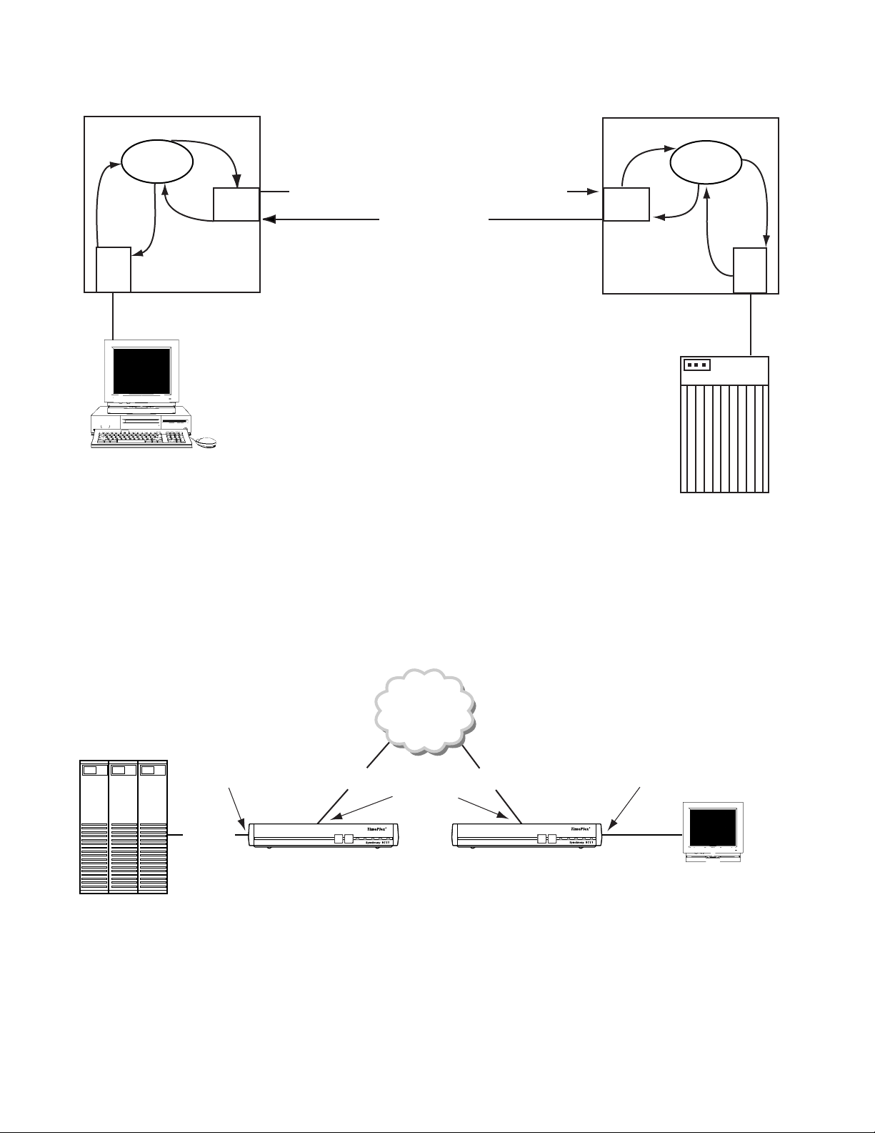
4 CHAPTER 1: GENERAL
c
o
n
n
r
e
n
n
o
c
e
r
Term
OS
q
c
c
o
n
f
n
n
o
c
o
c
q
o
n
n
n
X.25
f
Call request: userdata = HOSTA/01
Call accept
n
o
c
n
q
e
r
X.25
c
o
n
OS
n
n
o
c
f
n
o
c
c
o
c
n
o
n
n
f
r
e
q
Host
n
HOSTA
Processor
Address: 01
Default Host
A Connection
HOST
Figure 1-1
Figure 1-2 provides an example of how the MultiPro units establish connections. In
Example
this example two 9111s are connected using the Frame Relay network via each
device’s Port 1. Unit 001 has a host device connected to port 3: unit 002 has a
terminal device connected to port 4. All address tables and endpoint checklists
have been configured as shown.
PORT 1 Configured as:
Frame Relay
Endpoint List: DLCI 0015
[HOST]
PORTS 3
UNIT 001 UNIT 002
HOSTA
PORT 3 Configured as:
Poll/Select Terminal
Host Name: [HOSTA]
Connection Request Process
Frame Relay
DLCI 15 DLCI 16
PORTS 1
DOWNLOADCONFIG
MODEBACKUP NET ALARM POWER
PORT 4 Configured as:
Poll/Select Terminal
Address List: [AA] Connect [HOSTA]
PORT 1 Configured as:
Frame Relay
Endpoint List: DLCI 16 [HOST]
PORTS 4
DOWNLOADCONFIG
MODEBACKUP NET ALARM POWER
Terminal
Address = AA
Figure 1-2
9111 to 9111 Units Connected over Frame Relay
Page 27
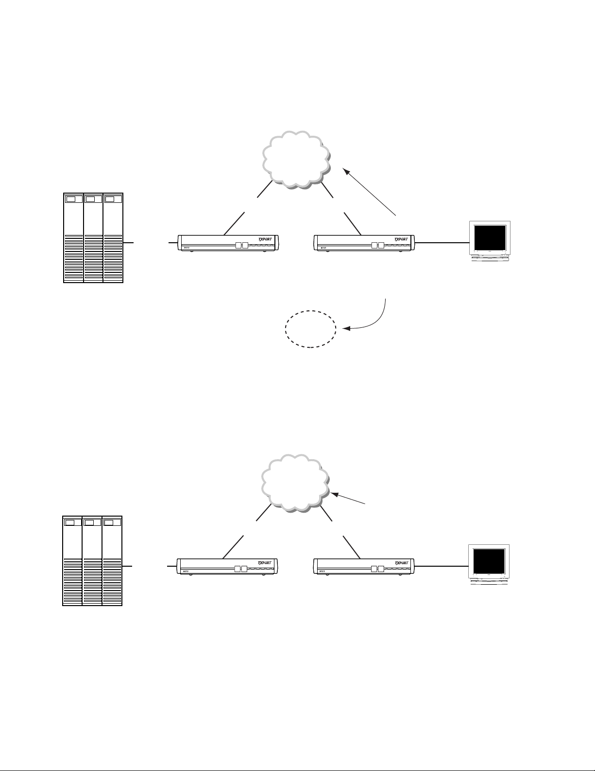
HOSTA
Principl es and Conc epts
Consider the scenario where both units have recently powered up, or been reset.
Port 4 on Unit 2 polls the first device, terminal AA, in its address list and gets a
response. After receiving this response, Port 4 issues a connect request to HOSTA,
the corresponding connect name for address AA. The connect request to HOSTA is
issued to Unit 002’s Operating System (OS), as shown Figure 1-3.
Frame Relay
DLCI 15 DLCI 16
UNIT 002
DOWNLOADCONFIG
MODEBACKUP NET ALARMPOWER
DOWNLOADCONFIG
MODEBACKUP NET ALARMPOWER
5
HOST
HOSTA
PORT 4 to OS
Connection request to HOSTA
Terminal
Address = AA
OS
Figure 1-3
Unit 002’s OS receives the connection request to HOSTA and finds HOSTA defined
in Port 1’s Endpoint List. The connection request is passed to Port 1. Port 1
receives the connection request to HOSTA from unit 002’s OS, and upon finding
HOSTA in its Endpoint List, transmits a call request to HO STA out the Frame
Relay connection, over DLCI 16, as shown in Figure 1-4.
Connect Request to HOSTA Is Issued to Unit 002’s Operating System
Frame Relay
PORT 1 to FRY:
Call request to HOSTA
DLCI 15 DLCI 16
UNIT 002
DOWNLOADCONFIG
MODEBACKUP NET ALARMPOWER
DOWNLOADCONFIG
MODEBACKUP NET ALARMPOWER
HOST
Figure 1-4
Terminal
Address = AA
Port 1 Transmits a Call Request to HOSTA
Page 28
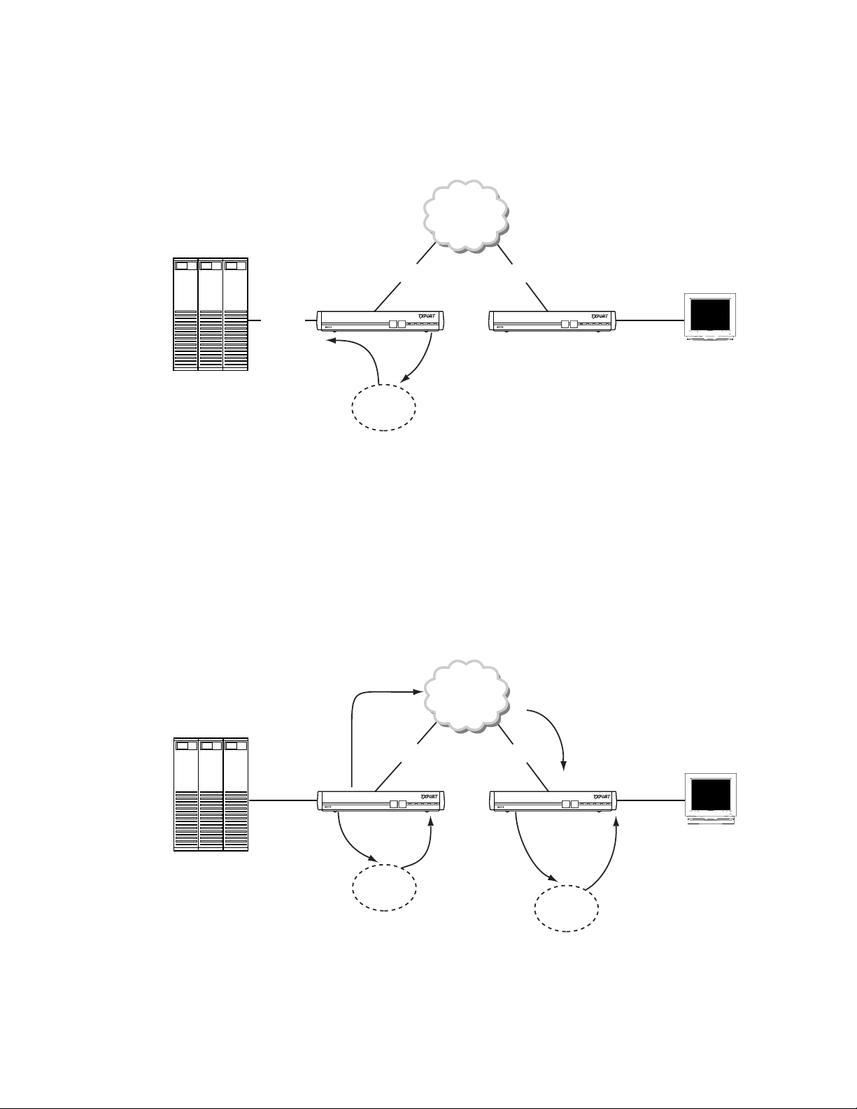
6 CHAPTER 1: GENERAL
After receiving a call request to HOSTA, Port 1 on unit 001 forwards the request
as a connection request to HOSTA to its own OS. Upon receiving the connection
request to HOSTA, unit 001’s OS finds that HOSTA is defined in Port 3’s HOST
Name field. The connection request to HOSTA is then passed to Port 3 on unit
001, as shown in Figure 1-5.
HOSTA
Frame Relay
DLCI 15 DLCI 16
DOWNLOADCONFIG
MODEBACKUP NET ALARM POWER
UNIT 002
DOWNLOADCONFIG
MODEBACKUP NET ALARM POWER
HOST
OS to PORT 3:
Connection request
to HOSTA
PORT 1 to OS:
Connection request to HOSTA
Terminal
Address = AA
OS
Figure 1-5
Connection Request to HOSTA Passed to Port 3
Unit 001’s Port 3 receives the connection request to HOSTA, and verifies that
HOSTA is defined on the port. A connect confirmation to HOSTA is returned t o the
OS, and the connect confirmation to HOSTA traverses to Port 4 on unit 0 02, the
originator of the connect request to HOSTA, as is shown in Figure 1-6.
After the connect confirmation has traversed to Port 4 of Unit 002, a logical
connection is established. This logical connection is between the terminal on Port
4 of unit 002, whose address is AA, and Port 3 of unit 001, which is connected to
an external host. This logical connection remains until the unit is reset or optioned
to disconnect under specific circumstances.
PORT 1 to FRY:
Call accept to
HOSTA
DLCI 15 DLCI 16
Frame Relay
FRY to PORT 1:
Call accept to HOSTA
HOST
PORT 3 to OS:
Connect confirmation
to HOSTA
Figure 1-6
Connect Request to HOSTA
OS
DOWNLOADCONFIG
MODEBACKUP NET ALARM POWER
OS to PORT 3:
Connect confirmation
to HOSTA
UNIT 002
DOWNLOADCONFIG
OS
PORT 1 to OS:
Connect confirmation
to HOSTA
MODEBACKUP NET ALARM POWER
Terminal
Address = AA
OS to PORT 4:
Connect confirmation
to HOSTA
Page 29
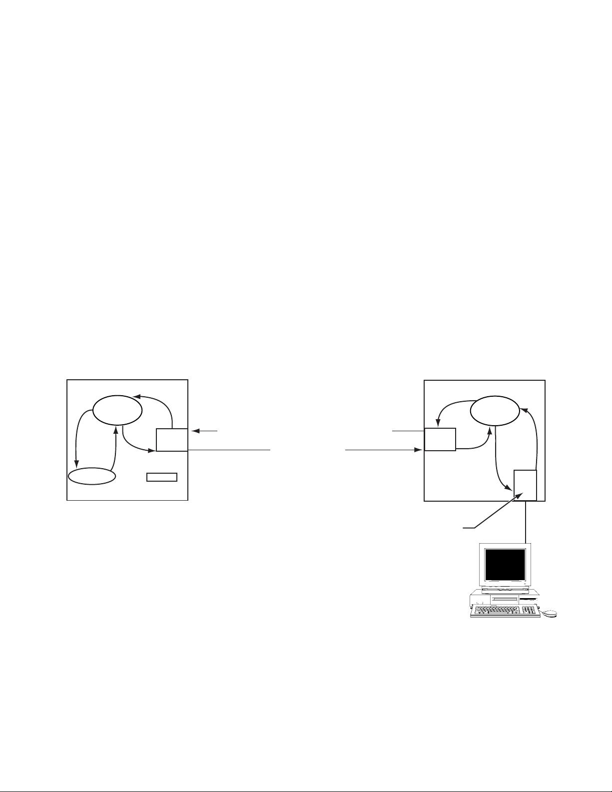
Principl es and Conc epts
7
Connecting for
Network
Management
Network management control software (NMCS) connections are required so each
unit in a network may be controlled from a central PC-based management
application. These connections are established just as if they were a normal station.
In fact, the network management PC connects a Poll/Select host port configured on
the MultiPro Plaform. Conventionally, the MultiPro Plaform is designated as the
single entry point into the MultiPro Plaform network. From this single unit and by
establishing connections as outlined previously, network management for every
unit in the MultiPro Plaform network can be accomplished. Tasks such as
configurations, status monitoring, and even downloading software modules can be
carried out on every TXPORT MultiPro Plaform in the network. The only method
for the MultiPro Plaform to establish a network connection is to have the NMCS
host port initiate the connection. Normally, the NMCS port is configured as a
Unisys Poll/Select host, and connects directly into the network manager’s PC.
Initiating the connection from the NMCS host port is done by defining the host
port with automatic connections to the unit number of the remote MultiPro
Plaform. The unit number can be viewed as the name of the unit entered upon
configuration. The host port initiates a connect request to the OS which then
forwards the request through the network to the proper destination. When the
remote unit receives the call, it confirms the connection as long as the destination
name carried in the user data field matches its own unit number. The logical
pathway is now established and commands can be sent by the NMCS application.
Figure 1-7 shows this process.
Unit 001 Unit 000
c
o
n
r
e
n
n
o
q
c
e
r
Console
OS
n
n
o
c
c
c
o
f
n
o
c
q
o
n
n
n
f
X
Network host = <blank>
n
X.25
Figure 1-7
Call request: userdata = 001/01
Call accept
Connecting for Network Management
n
n
o
c
q
e
r
X.25
c
Address 01 automatic
connection to 001
o
c
n
n
n
o
OS
f
c
o
c
o
n
f
NMCS
c
o
n
r
e
n
q
n
n
Host
NMCS
Page 30

8 CHAPTER 1: GENERAL
Features
✦ Modular Design
● Base unit with three user/WAN ports (9111)
● Base unit with four user/WAN ports (9211)
● Chassis unit with four user/WAN ports (9000)
● Optional LAN card (Ethernet) (9000, 9111, and 9211)
● Optional DDS and T1 cards (9111)
● Optional two-user port card (9111)
✦ Protocol flexibil ity
● Wide range of legacy, LAN, and WAN protocols
● Branch office routing and switching
● Supports frame relay and X.25 over all transmission media
● RFC 1490 support
✦ Advanced management techniques
Specifications
Serial
Interfaces
● Integrated SNMP management
● Self-Learning functionality
● Remote port monitoring
● WAN bandwidth management
✦ Data compress ion
✦ Data Integrity
● Guaranteed message delivery in frame relay environment
✦ Alternate path routing in frame relay and X.25
✦ Five-year warranty
9000: 6400 chassis holds one to three 9000 cards, 6800 chassis
holds one to eight 9000 cards
Four ports per each 9000 card: software-configurable
DTE/DCE, RS-232, TDI, and V.35; on a DB-25, female
Optional Ethernet interface with 10 Base-T on an RJ-48,
female and AUI on a DB-15, female
9101: Port 1: DDS; 56 kbps; RJ-48S, female
Port 2: DTE; V.35, 1.2 to 38.4 kbps w/character-oriented
protocols and 2.4 kbps to 2.048 Mbps w/bit-oriented
protocols; DB-25, female
Ethernet inte rface with 10 Bas e-T on an RJ-48, fe male
Page 31

Specifications
9111: Port 1: DDS; 56 or 64 kbps; RJ-48S, female or
T1; 1.054 Mbps; RJ-48S, female
Port 2: DTE; RS-232 or V.35 (depending on a jumper
on the main PCB), 1.2 to 38.4 kbps w/character-oriented
protocols and 2.4 kbps to 2.048 Mbps w/bit-oriented
protocols; DB-25, female
Port 3 and Port 4: DCE, RS-232, 1.2 to 38.4 kbps
w/character-oriented protocols and 2.4 kbps to 128 kbps
w/bit-oriented protocols; DB-25, female
Optional Ethernet interface with 10 Base-T on an RJ-48,
female
Optional Port 5 and Port 6: DCE or DTE (depending on
jumpers on the option card), RS-232, 1.2 to 38.4 kbps
w/character-oriented protocols and 2.4 kbps to 128 kbps
w/ bit-oriented protocols; DB-25, female
9211: Ports 1- 4: software-configurable DCE or DTE; RS-232, TDI,
or V.35, 1.2 to 38.4 kbps w/character-oriented protocols and
2.4 kbps to 2.048 Mbps w/bit-oriented protocols;
DB-25, female
9
9111 Port 1
DDS
Option
Optional Ethernet interface with 10 Base-T on an RJ-48,
female and AUI on a DB-15, female
Optional TDI module to support Unisys TDI interface
at any ports
Network Interface.
Line Rate: 56 and 64 kbps
Line Code: AMI
Line Impedance: Balanced 135 Ω
Input Signal: +1 to -40 dB (ALBO)
Output Signal: 3.0 V (±15%) base-peak into 135 Ω
Line Protection: 1000 V lightning, input and output
Industry Standards.
FCC Compliance: Part 15 Subpart B, Class A, Part 68
U.S. Safety: UL 1950, 3
rd
Edition
Canadian Safety: CSA C22.2 No. 950-95, Issue 8
Industry Canada: CS-03 Issue 8
9111 T1
Por t 1
Option
Network Interface.
Line Rate: 1.544 Mbps (± 50 bps)
Line Framing: D4 or ESF
Line Code: AMI or B8ZS
Page 32

10 CHAPTER 1: GENERAL
Line Impedance: balanced 100 Ω (± 5%)
Input Signal: DS1, +1 to - 27 dB (ALBO)
Output Signal: 3.0 V (±15%) base-peak into 100 Ω
Line Build Out: 0, -7.5, -15, and -22.5 dB attenuation
Line Protection: 1000 V lightning, input and output
Jitter Control: per TR62411 and T1.403
Pulse Density: per TR62411
Industry Standards.
FCC Compliance: Part 15 Subpart B, Class A, Part 68
U.S. Safety: 1950 3
Canadian Safety: C22.2 No. 950-95
IC: CS-03, Issue 8
ANSI T1.403: 1989
TR54016: April 1988
TR 62411: December 1990
rd
Edition
LAN Interface
Protocols
Connection: 10 Base -T, RJ-48
Ethernet: ISO/IEC 802-3
IBM: SNA/SDLC, SNA/RJE, 3780 BSC, 3270 BSC, 5250,
NCR: Poll/Select, UNIX X.25
Unisys: Poll/Select, T27 emulation, Uniscope
TTY: Host, Terminal, Printer
The protocol suite supported must be specified when ordering.
Logical Addresses
Supported: 512 (9101, 9111, and 9211) 1500 (6400 and 6800)
IP Routing Protocols: IP, RIP, RIP-II, and OSPF
IPX Routing
Protocols: IPX, RIP, SAP, and NLSP
LAN Protocols: Novell IPX, TCP/IP, NetBios, DECNet, XNS,
Banyan VINES, AppleTalk
WAN Protocols: Frame Relay, X.25, Full-Duplex Multi-Drop, IP PAD
WAN Media: Analog and digital leased lines, dial lines, Switched 56,
ISDN, microwave links, satellite links
Filtering: Station filtering and protocol filtering
Bridging Protocols: Transparent bridging with full IEEE 802.1d support
Page 33

Specifications
11
Management
Mechanical
Supervisory
Connection: RJ-48
Rates: 1.2 kbps to 115.2 kbps
SNMP Connection: In-band
Standards: RFC 1157 (SNMP), RFC 1213 (MIB-II),
TXPORT MIB extensions
Mounting: Desktop and horizontal rackmount (6400, 9101, 9111, and
9211)
Desktop only (6800)
Dimensions: 6400: 17.8" (45.1 cm) wide, 7.25" (18.4 cm) high,
17.0" (43.2 cm) deep
6800: 19" (48.3 cm) wide, 12.5" (31.3 cm) high,
17.5." (44.5 cm) deep
9101, 9111, and 9211:
12" (30.5 cm) wide, 2" (5.1 cm) high,
9" (22.9 cm) deep
Weight: 9101, 9111, and 9211: 3 pounds (1.36 kg)
6400: 30 pounds (13.6 kg)
Power
Environmental
6800: 60 pounds (27.3 kg)
9101, 9111,
and 9211: 115/230 VAC; 60/50 Hz; 69 W, max.
6400: 100 to 240 VAC; 50/60 Hz; 180 W, max.
6800: 100 to 240 VAC; 50/60 Hz; 300 W, max.
Operating
Temperature: 0°C to 40°C (32°F to 113°F)
Storage
Temperature: -20°C to 85°C (-4°F to 185°F)
Humidity: 95% maximum, non-condensing
Page 34

12 CHAPTER 1: GENERAL
Ordering
Numbers
Each MultiPro plaform is supplied with the following standard equipment:
✦ AC-to-DC power supply (p.n. 24-00108)
✦ Supervisory cable and adapter kit (kit p.n.: 9-1001-095-1 composed of p.n.
9-9100-006-1: adapter, DB-9 to RJ-48, male and p.n. 9-1544-619-010: cable,
RJ-48 to RJ-48, pin-to-pin w/drain, 10-foot)
✦ Telco cable (p.n. 9-1544-619-010: cable, RJ-48 to RJ-48, pin-to-pin w/drain,
10-foot)
✦ Modem adapter (p.n. 9-9100-005-1) to connect the supervisory port to a modem
with the telco cable (p.n. 9-1544-619-010)
The optional equipment shown in Table 1-1 is for the installation and operation of
MultiPro unit s.
Ta b l e 1- 1
Part Number Description
Supervisory Ca bles
9-9100-006-2
9-1001-619-009
9-1001-009-001
Ordering Numbers and Optional Equipment
8-pin jack to 9-pin D-type (PC-com L) adap ter
8-pin to 8-pin mod straight through cable
8-pin to 8-pin mod rollover cable
RS-232 Cables
9-1001-044
9-1001-211
9-1001-212
Chassis and Power Supplies
F-1800-064--1111
F-1800-064--1121
F-1800-068--111
9-1800-050--1
9-1800-008--1
9-1800-051--1
9-1800-009--1
9-1800-057--1
9-9100-028-1
Model 9000 MultiPro Platform Cards
F-1800-090--1100A
F-1800-090--1101A
F-1800-090--1110A
F-1800-090--1111A
Cables for Model 9000 MultiPro Platform Cards
9-1800-038-1
9-1800-047-1
Null modem male to male (RS-232)
RS-232 straight through male to male cable
RS-232 straight through male to female cable
Model 6400 3-Slot w/single power supply
Model 6400 3-Slot w/redundant power supply
Model 6800 8-Slot
6400 Chassis power supply (s/n≥ 504)
6400 Chassis power supply (s/n ≤ 503)
6400 Chassis redundant power supply (s/n ≥504)
6400 Chassis redundant power supply (s/n ≤503)
6800 Chassis power supply
9101, 9111, and 9211 DC - to - DC power supply
Model 9000 MultiPro Platform Card
Model 9000 MultiPro Platform Card w/TDI interfaces
Model 9000 MultiPro Platform Card w/Ethernet interface
Model 9000 MultiPro Platfo rm Card w/Ethernet a nd TDI interface s
Male DB-25 to V.35 male cab le
Female V.35 to Female V.35 cable adapter
Page 35

Ordering Numbers
13
Ta b l e 1- 1
Ordering Numbers and Optional Equipment
Part Number Description
9101 MultiPro Platforms
F-9101-001--11100
9101 MultiPro Platform w/1 port
9111 MultiPro Platforms
F-9111-001--11100
F-9111-001--11110*
F-9111-001--11101
F-9111-001--11102
F-9111-001--11111
F-9111-001--11112*
9111 MultiPro Platform w/3 ports
9111 MultiPro Platform w/3 ports and an integral 56 kbps CSU/DSU
9111 MultiPro Platform w/dual RS-232 expansion module
9111 MultiPro Platform w/3 por ts and Ethernet
9111 MultiPro Platform w/DDS and dual RS-232 expansion module
9111 MultiPro Platform w/3 ports, an integral 56 kbps CSU/DSU,
and Ethernet
* An 8-pin netwo rk interface ca ble is included .
9211 MultiPro Platforms
F-9211-001--11100
F-9211-001--11110
F-9211-001--11111
9211 MultiPro Platform w/4 ports
9211 MultiPro Platform w/4 por ts and Ethernet
9211 MultiPro Platform w/4 por ts, Ethernet, and TDI
Cables for 9101, 9111, and 9211 MultiPro Platforms
9-1001-052-005
9-1001-053-005
9-9100-007-1
Male DB-25 to male V.35 cable
Male DB-25 to female V.35 cable
RS-232 to TDI converter
MultiPro Platform Management Softwa re
9-8300-001-1
9-8300-001-2
9-8300-002-1
TCP TXPORT Configuration Program
NMCS Network Management and Contro l System
WinManager™ by Ordino x Networks, Inc.
Page 36

14 CHAPTER 1: GENERAL
Ta b l e 1- 1
Ordering Numbers and Optional Equipment
Part Number Description
9000 and 9211 Softw are
9-201-9155-1
9-201-9128-1
9000 Core
9211 Core
Applications
9-201-9130-1
9-201-9134-1
9-201-9148-1
9-201-9136-1
9-201-9152-1
9-201-9531-1
9-201-9137-1
Console (App endix A on page 379)
Transparent Bridge (Chapter 17 on page 277)
IP Layer (Chapter 15 on page 259)
IP PAD (Chapter 14 on page 243)
IP Router (Chapter 18 on page 287)
IPX Router (Chapter 19 on page 311)
SNMP (Chapter 16 on page 265)
Protocols
9-201-9150-1
9-201-9142-1
9-201-9143-1
9-201-9142-1
9-201-9139-1
9-201-9140-1
9-201-9132-1
9-201-9144-1
9-201-9145-1
9-201-9146-1
9-201-9134-1
9-201-9135-1
9-201-9131-1
Asychronous TTY (Chapter 6 on page 101)
Bisync 3270 Term inal (Chapter 7 on page 113)
Bisync 3270 Host (Chapter 7 on page 113)
Bisync 2780/3780 Terminal (Chapter 7 on page 113)
Unisys Poll /Select Term inal (Chapter 5 on page 85 )
Unisys Poll /Select Host (Chapter 5 on page 85)
Frame Relay (Chapter 12 on page 205)
NCR Terminal (Chapt er 8 on page 131)
NCR Host (Chapter 8 on page 131)
SDLC/HDLC LAPB (Chapter 11 on page 185)
Unisys Uniscope Terminal (Chapter 9 on page 149)
Unisys Uniscope Host (C hapter 9 on page 14 9)
X.25 (Chapter 13 on pa ge 223)
Page 37

Ordering Numbers
15
Ta b l e 1- 1
Ordering Numbers and Optional Equipment
Part Number Description
9101 and 9111 Softw are
9-201-9101-1
9-201-9101-1
9101 Core
9111 Core
Applications
9-201-9103-1
9-201-9102-1
9-201-9160-1
9-201-9112-1
9-201-9122-1
9-201-9110-1
9-201-9126-1
9-201-9127-1
9-201-9111-1
Legacy Console (Appendix A on page 379)
Console w/ LAN (App endix A on page 379)
Routing Console (Appendix A on page 379)
Transparent Bridge (Chapter 17 on page 277)
IP Layer (Chapter 15 on page 259)
IP PAD (Chapter 14 on page 243)
IP Router (Chapter 18 on page 287)
IPX Router (Chapter 19 on page 311)
SNMP (Chapter 16 on page 265)
Protocols
9-201-9124-1
9-201-9116-1
9-201-9117-1
9-201-9116-1
9-201-9113-1
9-201-9114-1
9-201-9106-1
9-201-9118-1
9-201-9119-1
9-201-9120-1
9-201-9108-1
9-201-9109-1
9-201-9105-1
Asychronous TTY (Chapter 6 on page 101)
Bisync 3270 Term inal (Chapter 7 on page 113)
Bisync 3270 Host (Chapter 7 on page 113)
Bisync 2780/3780 Terminal (Chapter 7 on page 113)
Unisys Poll /Select Term inal (Chapter 5 on page 85 )
Unisys Poll /Select Host (Chapter 5 on page 85)
Frame Relay (Chapter 12 on page 205)
NCR Terminal (Chapt er 8 on page 131)
NCR Host (Chapter 8 on page 131)
SDLC/HDLC LAPB (Chapter 11 on page 185)
Unisys Uniscope Terminal (Chapter 9 on page 149)
Unisys Uniscope Host (C hapter 9 on page 14 9)
X.25 (Chapter 13 on pa ge 223)
Page 38

16 CHAPTER 1: GENERAL
TXPORT
Customer
Service
Support from
Your Network
Supplier
Support from
TXPORT
Telephone
TXPORT provides easy access to customer support information through a variety
of services. This section describes these services.
If assistance is required, contact your network supplier. Many suppliers are
authorized TXPORT service partners who are qualified to provide a variety of
services, including network planning, installation, hardware maintenance,
application training, and support services.
When you contact your network supplier for assistance, have the following
information ready:
✦ Diagnostic error messages
✦ A list of system hardware and software, including revision levels
✦ Details about recent configuration changes, if applicable
If you are unable to receive support from your network supplier or want to contact
us directly, TXPORT offers worldwide customer support 24 hours a day, 7 days a
week by telephone, E-mail, and World Wide Web.
To speak directly with a TXPORT customer service representative, dial, toll free,
one of the following numbers or dial TXPORT’s local telephone number.
E-mail
World
Wide
Web
✦ Sales and Marketing: 888 -4TXPORT
✦ Technical Support
✦ Local: 256- 772 - 3770
:
800 -285- 2755
You can request sales and marketing information or pose a technical support
question about your TXPORT product with direct e-mail access.
✦ Sales and Marketing: info@txport.com
✦ Technical Support: support@txport.com
Access the latest networking information on TXPORT’s World Wide Web site by
entering our URL into your internet browser.
http://www.txport.com/
This service features information about TXPORT products, customer service,
technical support, latest news releases, and more.
Page 39

Returning Products
17
Returning
Products
If for any reason you m ust retu rn your TXPORT product, it must be r eturn ed to th e
factory, shipping prepaid and packaged to the best commercial standard for
electronic equipment. TXPORT will pay shipping charges for delivery on return.
You are responsible for mode and cost of shipment to TXPORT.
You must have a Return Material Authorization (RMA) number marked on the
shipping package. Products sent to TXPORT without RMA numbers will be
returned to the sender unopened, at the sender’s expense. A product sent directly to
TXPORT for repair must first be assigned a Return Materials Authorization
(RMA) number.
You may obtain an RMA number from customer service at 800-926-0085, ext.
2282. When ca lling TXPO RT for an RMA, please have the fo llowing informatio n
availab le.
✦ Model number and serial number for each unit.
✦ Reason for return and symptoms of problem.
✦ Warranty sta tus (if known).
✦ Purchase order number to cover charges for out- of -warranty items.
✦ Name and phone number of person we can contact if we have questions about the
unit(s).
✦ Mode of shipment required (second-day air is the normal mode of shipment for all
returned material unless otherwise specified).
Units being returned to TXPORT should be sent to the following address.
TXPORT
127 Jetplex Circle
Madison, Alabama 35758
Page 40

18 CHAPTER 1: GENERAL
Page 41

2
✍
I
NSTALLATION
Introduction
Safety Summary
Unpacking and
Inspection
This chapter contains information and instructions required to prepare TXPORT
MultiPro platforms for use. Included are initial inspection procedures, connections,
and powering info rmation.
The 9101, 9111, and 9211 units are shipped ready for desktop use.
This manual contains information and warnings which must be followed by the
user to ensure safe operation and to retain the equipment in a safe condition.
This WARNING sign denotes a potential hazard to the operator. It calls attention to a
procedure or practice which, if not correctly performed or adhered to, could result in
injury or loss of life. Do not proceed beyond a WARNING sign until the indicated conditions
are fully understood and met.
This unit is carefully packaged to prevent damage in shipment. Upon receipt,
inspect the shipping container for damage. If the shipping container or cushioning
material is damaged, notify the carrier immediately and make a notation on the
delivery receipt that the container was damaged (if possible, obtain the signature
and name of the person making delivery). Retain the packaging material until the
contents of the shipment have been checked for completeness and the instrument
has been checked both mechanically and electrically.
If the contents of the shipment are incomplete or, if there is mechanical damage or
defect, notify TXPORT. If the shipping container is also damaged, or the
cushioning material shows signs of stress, notify the carrier of the damage as well
as TXPORT. Keep the shipping materials for the carrier’s inspection. TXPORT
will arrange for repair or replacement without waiting for claim settlement.
Supplied
Materials
The 9101, 9111, and 9211 are shipped from the factory with the following
standard equipment:
✦ AC-to-DC power supply
✦ Supervisory cable (9-1544-619-010) and adapter (9-9100-006-2)
For specific applications, additional cables and adapters may be required for the
installation and operation of the unit. The interface requirements of any application
may be met by using the appropriate cable. Standard cables and TXPORT ordering
numbers are listed in Ordering Numbers and Optional Equipment on page 12.
Contact TXPORT for any needed assistance in cable selection.
The 9101, 9111, and 9211 MultiPro platforms may only be used with the
TXPORT-provided power supplies [p.n. 24-00108 (AC to DC) and p.n. 9-9100-028-1
(DC to DC)].
Page 42

20 CHAPTER 2: INSTALLATION
PWR
RESET
ETHERNET
SUPERVISORY
PORT 2
PORT 1
TXD
RXD
LINK
COL
118
113
1425
818
9101
Connections
AC Po we r
Figure 2-1 shows the rear panel of the 9101, including the power connector; reset
button; Ethernet connector and LEDs; supervisory connector; and connectors for
ports 1 and 2.
Figure 2-1
TXPORT 9101 Rear Panel and Power Supply
To power the unit from an AC source, connect the power supply (Figure 2-2) to the
unit, then connect the wall plug to the appropriate outlet. This applies power to the
unit.
APS
MODEL :APS20-ES-30
For use with computer
ADVANCED
POWER
SOLUTIONS
equipment
only
4121
9542
Figure 2-2
Ground
-12 VDC at 0.1A
+12 VDC at 0.1A
+5 VDC at 1.3A
AC Power Supply for the 9101, 9111, and 9211
Page 43
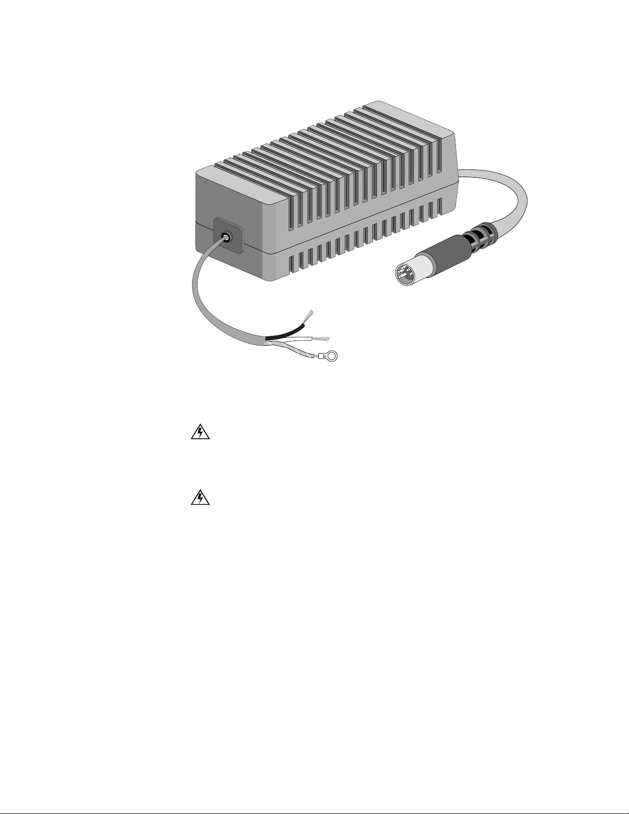
9101 Connections
Figure 2-3
DC Power Supply for the 9101, 9111, and 9211
21
DC Power
To power the unit from a DC source, use part number 9-9100-028-1, shown in
Figure 2-3). Follow the procedures below to connect and disconnect the power
supply. The power connection procedure applies power to the unit.
DC INPUT
20 to 60VDC
2.7
(BLK + )(WHT
A MAX
(GRN/YEL CHAS GND)
-
)
Black +
White -
Green/Yellow Chassis Ground
Connecting the DC Power Supply
WARNING: Before completing any of the following steps and to prevent short-circuit
or shock hazards, ensure that power removed from the DC circuit. To ensure that all
power is Off, locate the circuit breaker on the panel board that services the DC circuit,
switch the circuit breaker to the Off position, and tape the switch handle of the circuit
breaker in the Off position.
WARNING: When installing the unit, the ground connection must always be made first
and disconnected last.
1 Ensure that power is removed from the 48 volt sour ce as indicated in the first
warning above.
2 Connect the green/yellow chassis ground wire of the DC power supply to the
ground lug or screw of the 48 volt source.
3 Connect the black (+) wire of the DC power supply to the return screw of the 48
volt source.
4 Connect the white (−) wire of the DC power supply to the −48 volt screw of the
48 volt source.
5 Connect the D C power supply to th e MultiPro un it.
6 Apply power to the circuit. This applies power to the MultiPro unit.
Page 44

22 CHAPTER 2: INSTALLATION
Disconnecting the DC Power Supply
1 Remove power from the DC source as indi cated in the first warning above.
2 Remove the DC power supply connector from the MultiPro unit.
3 Disconnect the white (−) wire of the DC power supply to the − 48 volt screw of the
48 volt source.
4 Disconnect the black (+) wire of the DC power supply to the return screw of the
48 volt source.
5 Disconnect the green/yellow chassis ground wire of the DC power supply to the
ground lug or screw of the 48 volt source.
Supervisory
Por t
Ethernet Port
The Supervisory port allows local, direct
connection of the unit to a dumb terminal or a
PC running a terminal emulation program
using the 9-9100-006-2 adapter and
9-1544-619-010 Supervisory cable. The form
factor of the connector is an RJ-48. Table 2-1
shows the pinout .
For remote applications, the Supervisory port
can also be connected to a modem using the
9-1544-619-010 cable and a 9-9100-005-1
adapter.
Table 2-2 shows the pinout of the Ethernet port.
Ta b l e 2 - 1
Pin Signal
1 DTE R eady (DTR)
2 Clear to Send (CTS)
3 Signal Ground (SG)
4 Receive D ata (RXD)
5 Transmit Data (TXD)
6 Frame Ground
7 Request to Send (RTS)
8 Data Set Ready (DSR)
Tab l e 2 - 2
Supervisory Port Pinout
Ethernet Port Pinout
Pin Signal
1 Data Out (+)
2 Data Out (-)
3 Data In (+)
4, 5, 7, 8 not used
6 Data In (-)
Indicators
The Ethernet LED
indicators are located to the
right of the Ethernet
connector. Table 2-3 shows
how to interpret them .
Tab l e 2 - 3
Indicator Interpretation
TXD The Ethernet port is transmitting data.
RXD The Ethernet port is receiving data.
LINK The unit is physically linked to a network.
COL There is a data collision.
Ethernet LED Interpretation
Page 45

9101 Connections
Ta b l e 2 - 4
Port 1 Pinout
Pin Signal
1 R (output to network)
2 T (output to network)
3, 4, 5, 6 not used
7 T1 (input from network)
8 R1 (input from network)
23
Por t 1
Por t 2
Port 1 is a DDS port with a data rate of 56
kbps. The form factor of the connector is an
RJ-48S. Table 2-4 shows the pinout.
Port 2 is a DTE port. Its
Ta b l e 2 - 5
Port 2 Pinout
interface is V.35.
Table 2-5 shows the
pinout of Port 2.
Signal
Shield Ground AA 1 FG 1
Transmit Data BA 2 SD 2/14
Receive Data BB 3 RD 3/ 16
Request to Send CA 4 RTS 4
Clear to Send CB 5 CTS 5
Data Set Ready CC 6 DSR 6
Signal Ground AB 7 SG 7
Data Carrier Detect CF 8 RLSD 8
Transmit Clock DB 15 SCT 15/12
Receive Clock DD 17 SCR 17/9
DTE Ready C D 20 DTR 20
External Clock DA 24 SCTE 24 / 11
RS-232C
Circuit Pin
V.35
Circuit
Pins
A/B
Page 46

24 CHAPTER 2: INSTALLATION
PWR
RESET
ETHERNET
SUPERVISORY
1357911
2 4 6 8 10 12
T1
PORT 2PORT 3PORT 4
TXD
RXD
LINK
COL
ON
123456789101112
9111
Connections
Supervisory
Ethernet Port
Pow er
Por t
Figure 2-4 shows the rear panels of the 9111, including the power connector; reset
button; Ethernet connector and LEDs; supervisory connector; and connectors for
ports 1 through 4.
Connect the power supply [shown on page 20 (AC to DC) and page 21 (DC to
DC)] to the 9111. This applies power to the unit.
The Supervisory port allows local, direct
Ta b l e 2 - 6
Supervisory Port Pinout
connection of the unit to a dumb terminal or a
PC running a terminal emulation program
using the 9-9100-006-2 adapter and
9-1544-619-010 Supervisory cable. The form
factor of the connector is an RJ-48. Table 2-6
shows the pinout .
For remote applications, the Supervisory port
can also be connected to a modem using the
9-1544-619-010 cable and a 9-9100-005-1
Pin Signal
1 DTE R eady (DTR)
2 Clear to Send (CTS)
3 Signal Ground (SG)
4 Receive D ata (RXD)
5 Transmit Data (TXD)
6 Frame Ground
7 Request to Send (RTS)
8 Data Set Ready (DSR)
adapter.
Ta b l e 2 - 7
Ethernet Port Pinout
Table 2-7 shows the pinout of the Ethernet port.
Indicators
The Ethernet LED
indicators are located to the
right of the Ethernet
connector. Table 2-8 shows
how to interpret them .
Ta b l e 2 - 8
Indicator Interpretation
TXD The Ethernet port is transmitting data.
RXD The Ethernet port is receiving data.
LINK The unit is physically linked to a network.
COL There is a data collision.
Ethernet LED Interpretation
Pin Signal
1 Data Out (+)
2 Data Out (-)
3 Data In (+)
4, 5, 7, 8 not used
6 Data In (-)
Figure 2-4
9111 with Port 1 T1 Option
Page 47

9111 Connections
65431 2
56 kbp s
Alternate
64 kbps
Cont ig u o us
A
B
Network Clo c k
(Loo p ed )
Inte r na l Clo ck
(Mas ter)
D4
ESF
B8ZS
AMI
LBO
Network
A A
B
A
B
A
B
B
0
-22.5
-7.5
-15
12119 1087
Figure 2-5
Switch S1
DS0s Assigned
(see Table 2-10)
25
9111
Por t 1
T1 Option
This section describes the 9111 Internal T1 Card. The card is a one-port T1
interface card for the 9111 MultiPro series unit. The module has an RJ-48
connector and is located above the supervisory port as shown in Figure 2-4. The
internal T1 card is configured using the switches located on the rear panel.
Switch S1
.
Switch S1 is a 12-position
DIP switch lo cated on the
rear panel of the 9111. This
switch provides th e
configuration parameters
shown in Table 2-9 and
Table 2-10
Ta b l e 2 - 9
1- 5
6
7
8
9
10
11, 12
Switch S1
DSOs Assigned:
These five positions select the bit rate and the number of DSOs
assigned to the channel (see Table 2-10).
Rate Multiplier:
Sets the multiplier for the input timing (see Table 2-10). The unit
operates at any data rate that is a multiple of 56 or 64 kbps.
Channel Assignment:
The Contiguous mode assigns the channels as a block
beginning at DS0 channel 1. If Alternate is selected, channel assign ments are made
with an idle channel following each data channel.
Timing Source:
Network Coding:
This switch determines the unit’s clocking source.
B8ZS or AMI. Because AMI mode is sensitive to zero-bit density,
B8ZS is recommended for a more robust configuration.
Network Framing:
Network LBO:
D4 or ESF only
These switches set the network signal level (in decibels) of data
transmitted towa rds the T1 facility . The signal level is de termined as shown in Figure 2-5 .
Page 48

26 CHAPTER 2: INSTALLATION
Table 2-10
DS0 S1-1 S1-2 S1-3 S1-4 S1-5 S1-6 (A) S1-6 (B)
1 B B B B B 56 kbps 64 kbps
2 B A B B B 112 kbps 128 kbps
3 A A B B B 168 kbps 192 kbps
4 B B A B B 224 kbps 256 kbps
5 A B A B B 280 kbps 320 kbps
6 B A A B B 336 kbps 384 kbps
7 A A A B B 392 kbps 448 kbps
8 B B B A B 448 kbps 512 kbps
9 A B B A B 504 kbps 576 kbps
10 B A B A B 560 kbps 640 kbps
11 A A B A B 616 kbps 704 kbps
12 B B A A B 672 kbps 768 kbps
13 A B A A B 728 kbps 832 kbps
14 B A A A B 784 kbps 896 kbps
15 A A A A B 840 kbps 960 kbps
16 B B B B A 896 kbps 1024 kbps
17 A B B B A 952 kbps 1088 kbps
18 B A B B A 1008 kbps 1152 kbps
19 A A B B A 1064 kbps 1216 kbps
20 B B A B A 1120 kbps 1280 kbps
21 A B A B A 1176 kbps 1344 kbps
22 B A A B A 1232 kbps 1408 kbps
23 A A A B A 1288 kbps 1472 kbps
24 A A A A A 1344 kbps 1536 kbps
DS0s Assigned
T1 Connection
Table 2-11 shows the the T1 connector pinout. The form factor of the connector is
an RJ-48.
Table 2-11
Pin Signal
1 Data In (R1)
2 Data In (R1)
3, 6 not used
4 Data Out (R)
5 Data Out (R)
7, 8 Chassis Ground
T1 Connector Pinout
Page 49

9111 Connections
PWR
RESET
ETHERNET
SUPERVISORY
56Kbps 64Kbps
SW1
DDS
PORT 2PORT 3PORT 4
TXD
RXD
LINK
COL
27
9111 Port 1
T1 Option
Testing
9111
Por t 1
DDS Option
CSU Line Loop
The CSU line loopback is activated by receiving a 1.544 Mbps signal, consisting of
a repeating one in five (00001) pattern with arbitrary 0s or 1s in every 193rd bit
position overwriting the pattern. This loopback is deactived by receiving a 1.544
MBPS signal, consisting of a repeating one in three (001) pattern with arbitrary
values every 193rd bit position overwriting the pattern. Figure 2-6 shows the line
loop.
CSU Line Loop (In-band LL B)
DTE
Figure 2-6
* Signal regeneration only
CSU Line Loop
NET
*
This section describes the 9111 Internal DDS Card. The card is a one-port DDS-I
interface card for the 9111 MultiPro series unit. The module has an RJ-48
connector and is located above the supervisory port as shown in Figure 2-7. The
internal DDS card is configured by positioning SW1 located on the rear panel.
Clocking is supplied from the network.
Figure 2-7
9111 with Port 1 DDS Option
Switch SW1
Switch SW1 is a 2-position switch located on the rear panel of the 9111 used to set
the channe l bit rate per DD S-I.
DDS Network Connection
The network DDS facility interface is an RJ-48C with the pinout shown in
Table 2-12..
Table 2-12
Pin Signal
1
2
3-6 not use d
7
8
DDS Connector Pinout
Network Transmit Out
Network Transmit Out
Network Data In
Network Data In
Page 50

28 CHAPTER 2: INSTALLATION
9111 Port 1
DDS Option
Testing
Por t 2
Remote Channel Loop
This loop is activated by
DTE
NET
receiving a minimum of four
consecutive bytes of the
Figure 2-8
Channel Loop
non-latching loopback code at
the proper data rate and remains looped as long as every other byte contains the
loopback code and continues for a minimum of four consecutive bytes after
receiving the last loopback code. Figure 2-8 shows the channel loop.
Port 2 is a DTE
able 2-13
Port 2 Pinout
port. Its
interface is
RS-232 or V.35,
depending on a
jumper on the
main PCB. The
default is V.35.
To change th is
jumper, see
Figure 2-9.
Table 2-13
shows the
pinout of Port 2.
RS-232C
Signal
Shield Ground AA 1 FG 1
Transmit Data BA 2 SD 2/14
Receive Data BB 3 RD 3/16
Request to Send CA 4 RTS 4
Clear to Send CB 5 CTS 5
Data Set Ready CC 6 DSR 6
Signal Ground AB 7 S G 7
Data Carrier Detect CF 8 RLSD 8
Transmit Clock DB 15 SCT 15/12
Receive Clock DD 17 SCR 17/9
DTE Ready CD 20 DTR 20
External Clock DA 24 SCTE 24/11
Circuit Pin
V.35
Circuit
Pins
A/B
Page 51

Changing the Interface on Port 2
Standoff
PORT 2
Ethernet Card
DDS Card
J12
V.35
RS-232
J8
Front 9111
Figure 2-9
Location of Port 2 RS-232 / V.35 Header
CAUTION: The circuit b oards are su sceptible to d amage caus ed by static e lectrici ty.
Use electrostatic device (ESD) precautionary measures, such as wearing static
grounding straps and storing modules in antistatic bags.
1 Disconnect power from the
unit.
2 Remove all connections from
the unit.
3 Place the unit on an
ESD-approved work area.
4 Lay the unit on its top (upside
down) with the fro nt panel
toward you.
5 Remove the four screws in the
base of the unit using a
Phillips-h ead screwdriver.
9111 Connections
29
6 Lift the unit from underneath
and set it down on its base
with the front panel facing
you.
7 Remove the cover from t he
unit.
8 Remove the DDS or T1 card by removing the Phillips-head screw near J8,
pinching the two near white, plastic standoffs (refer to Figure 2-9) and slightly
lifting the DDS or T1 card, pinching the standoff near the connector Port 2, and
lifting the DDS or T1 card.
9 Gently lift and set the RS-232/V.35 jumper located on the motherboard beside J8
to the (refer to F igure 2-9) desired position .
10 Assemble the unit in reverse order, taking special care to properly reconnect J8 and
J12 when attaching the DDS card.
Page 52

30 CHAPTER 2: INSTALLATION
Figure 2-10
Front View of the 9111 Dual RS-232 Expansion Module
Por t 3
and
Por t 4
9111 Dual
RS-232
Expansion
Option
Module
Port 3 and Port 4 of the 9111 are DCE ports with an RS-232 interface. Table 2-14
shows the pinout of Port 3 and Port 4.
Table 2-14
Pin Signal
1 Shield Ground AA
2 Transmit Data Ba
3 Receive Data BB
4 Request to Send CA
5 Clear to Send CB
6 Data Set Ready CC
7 Signal Ground AB
8 Data Carrier Detect CF
15 Transmit Clock DB
17 Receive Clock DD
Port 3 and Port 4 Pinout
RS-232C
Circuit
Symbol
x
This section describes the 9111 Dual RS-232 Expansion Option Module. The
module is a two-port RS-232C serial interface card for the 9111 MultiPro series
unit. The module has two female DB-25 connectors (Port 5 and Port 6) and
occupies the same expansion slot as the Ethernet option card shown in Figure 2-4.
The interfaces for the module expand the capabilities of the 9111 to five ports. The
two expansion ports can be configured for either DCE or DTE by positioning the
jumpers located on the circuit board (see Figure 2-11). All other parameters are
configured through the console interface or through the NMCS program the same
as the other serial ports.
PWR
RESET
113
PORT 6 PORT 5
1425
25
113
SUPERVISORY PORT 1
PORT 2PORT 3PORT 4
113
PORT 6 PORT 5
1425
113
1425
Page 53

Port 5 and Port 6 Pinouts
JP12
9111 Connections
J1
JP1
2
3
4
5
6
7
8
9
10
JP11
J2
DTE
DCE
13
14
15
16
JP17
JP18
19
20
21
JP22
31
Figure 2-11
Top View of the 9111 Dual RS-232 Expansion Module
Table 2-15 shows the pinouts for Port 5 and Port 6.
Table 2-15
Signal
Shield Ground AA 1
Transmit Data BA 2
Receive Data BB 3
Request to Send CA 4
Clear to Send CB 5
Data Set Ready CC 6
Signal Ground AB 7
Data Carrier Detect CF 8
Transmit Clock DB 15
Receive Clock DD 17
DTE Ready CD 20
External Clock DA 24
Pinouts of Port 5 and Port 6
RS-232C
Circuit
Pin
Page 54

32 CHAPTER 2: INSTALLATION
PWR
RESET
ETHERNET
UTP
SUPV
PORT 1PORT 2PORT 3PORT 4
LINK
COL
RXD
TXD
1
1
13
1425
1
13
14 1425
1
13
1425
1
13
25
8
AUI
8
1
9
15
9211
Connections
Supervisory
Ethernet UTP Port
Pow er
Por t
Figure 2-12 shows the rear panels of the 9211, including the power connector;
reset button; UTP and AUI Ethernet connectors and LEDs; supervisory connector;
and connectors for ports 1 through 4.
Connect the power supply [shown on page 20 (AC to DC) and page 21 (DC to
DC)] to the 9211. This applies power to the unit.
The Supervisory port allows local, direct
Table 2-16
Supervisory Port Pinout
connection of the unit to a dumb terminal or a
PC running a terminal emulation program
using the 9-9100-006-2 adapter and
9-1544-619-010 Supervisory cable. The form
factor of the connector is an RJ-48. Table 2-16
shows the pinout .
For remote applications, the Supervisory port
can also be connected to a modem using the
9-1544-619-010 cable and a 9-9100-005-1
Pin Signal
1 DTE R eady (DTR)
2 Clear to Send (CTS)
3 Signal Ground (SG)
4 Receive D ata (RXD)
5 Transmit Data (TXD)
6 Frame Ground
7 Request to Send (RTS)
8 Data Set Ready (DSR)
adapter.
Table 2-17
Ethernet Port Pinout
Table 2-17 shows the pinout of the Ethernet
port. The for m factor of the c onnector is an
RJ-48.
Pin Signal
1 Data Out (+)
2 Data Out (-)
3 Data In (+)
4, 5, 7, 8 not used
6 Data In (-)
Figure 2-12
TXPORT 9211 Rear Panels and Power
Page 55

9211 Connections
Ta b l e 2 - 19
Ethernet LED Interpretation
Indicator Interpretation
TXD The Ethernet port is transmitting data.
RXD The Ethernet port is receiving data.
LINK The unit is physically linked to a
network.
COL There is a data collision.
33
AUI Po r t
Table 2-18 shows the
pinout of the AUI
(attachmen t unit
interface) port. The
form factor is female
DB-15.
Ta b l e 2 - 18
Pin Circuit Signal
1, 2, 6, 8, 9, 13, and 14 not used
3 DO-A Data Out, Circuit A
4 DI-S Data In, Circuit Shield
5 DI-A Data In, C ircuit A
7 CO-A Co ntrol Out, Circuit A1
10 DO-B Data Out, Circuit B
11 DO-S Data Out, Circuit Shield 1
12 DI-B Data In, Circuit B
15 CO-B Control Out, Circuit B
Indicators
The Ethernet LED indicators
are located to the right of the
Ethernet connector. Table 2-19
shows how to interpret the m.
AUI Port Pinout
Ports 1, 2,
3, and 4
Ports 1 through 4 are
softwareconfigurable serial
ports for V.35 or
RS-232 interface types
and DTE or DCE
termination . This
allows for greater
flexibility in
connections with a
wide variety of
configurations. The
default for P ort 1 is
Frame Relay V.35
DTE; Port 2 is Frame
Relay RS-232 DTE;
Port 3 is Poll/Select
Host RS-232 DCE;
Ta b l e 2 - 20
Signal
Shield Ground AA 1 FG 1
Transmit Data BA 2 SD 2/14
Receive Data BB 3 RD 3/16
Request to Send CA 4 RTS 4
Clear to Send CB 5 CTS 5
Data Set Ready CC 6 DSR 6
Signal Ground AB 7 SG 7
Data Carrier Detect CF 8 RLSD 8
Transmit Clock DB 15 SCT 15/12
Receive Clock DD 17 SCR 17/9
DTE Ready CD 20 DTR 20
External Clock DA 24 SCTE 24/11
Port 1, 2, 3, and 4 Pinout
RS-232C
Circuit
Symbol Pin
V.35
Circuit
Symbol
Pins
A/B
and Port 4 has no
default. The form factor of the connector is female DB-25. Table 2-20 shows the
pinout of these ports.
Page 56

34 CHAPTER 2: INSTALLATION
9000
Connections
Console
Power
Por t
Figure 2-13 shows the rear panels of the 9000, including the power connector;
UTP and AUI Ethernet connectors; supervisory connector; and connectors for ports
1 through 4.
Verify the chassis is not connected to a power source. Insert the 9000 MultiPro
platform card into the chassis. Plug the power cord into an appropriate outlet. This
applies power to the unit.
The Console port allows local, direct
Ta b l e 2 - 21
Console Port Pinout
connection of the unit to an ASCIIcharacter-based terminal or a PC running a
terminal emul ation program . The form
factor of the connec tor is female DB-9.
Table 2-21 shows the pinout.
Pins Signal
1 Carrier Detect (DCD)
2 Received Data (RD)
3 Transmitted Data (TD)
4 Data Terminal Ready (DTR)
5 Signal Ground (SG)
6 Data Set Ready (DSR)
7 Request to Send (RTS)
8 Clrear To Send (CTS)
9 not connected
Ethernet AUI Por t
Table 2-22 shows the
pinout of the AUI
(attachmen t unit
interface) port. The
form factor of the
connector is female
DB-15.
Ta b l e 2 - 22
AUI Port Pinout
Pin Circuit Signal
1, 2, 6, 8, 9, 13, and 14 not used
3 DO-A Data Out, Circuit A
4 DI-S Data In, Circuit Shield
5 DI-A Data In, Circu it A
7 CO-A Control Out, Circuit A1
10 DO-B D ata Out, Circuit B
11 DO-S Data Out, Circuit Shield 1
12 DI-B Data In, Circuit B
15 CO-B Control Out, Circuit B
13 1
PORT 1 PORT 2 PORT 3 PORT 4 CONSOLE AUI UTP
Figure 2-13
13 1
1425
13 1
1425
TXPORT 9000 Rear Panel
13 1
1425
591
1425
8811
15
6
9
Page 57

9000 Connections
UTP Port
Table 2-23 shows the pinout of the UTP port. The form factor of the connector is
an RJ-48.
35
Ports 1, 2,
3, and 4
Table 2-23
Pin Signal
1 Data Out (+)
2 Data Out (-)
3 Data In (+)
4, 5, 7, 8 not used
6 Data In (-)
UTP Port Pinout
Ports 1 through 4 are software-switchable serial ports for V.35 or RS-232 and DTE
or DCE. This allows for greater flexibility in connections with a wide variety of
configurations. The form factor of the connectors is female DB-25. Table 2-24
shows the pinout .
Table 2-24
Signal
Shield Ground AA 1 FG 1
Transmit Data BA 2 SD 13/14
Receive Data BB 3 RD 3/16
Request to Send CA 4 RTS 4
Clear to Send CB 5 CTS 5
Data Set Ready CC 6 DSR 6
Signal Ground AB 7 SG 7
Data Carrier Detect CF 8 RLSD 8
Transmit Clock DB 15 SCT 1 5/12
Receive Clock DD 17 SCR 17/9
DTE Ready CD 20 DTR 20
External Clock DA 24 SCTE 24/11
Ports 1, 2, 3, and 4 Pinout
RS-232C
Circuit Pin
V.35
Circuit
Pins
A/B
Page 58

36 CHAPTER 2: INSTALLATION
Page 59

3
DOWNLOAD CONFIG
MODE BACKUP NET ALARM POWER
PRISM 9111SERIES
H
ARDWARE
O
PERATION
Introduction
9101, 9111,
and 9211
Front Panel
Operation
Configuration
Mode
Ta b l e 3 - 1 Front Panel Controls and Indicators
Index Control /Indicator Function /Interpretation
1 DOWNLOAD To enter th e DOWNLOAD mode, press the RESET button, located on the rear
2 CONFIG To enter the CONFIG mode, press the RESET button, located on the rear of
3 MODE Flashing Green when the unit is in Run mod e.
4BACKUP
(green in 9101 and 9111 )
TD / RD
(green/red/amber in 9211)
5 NET (green) On when the network port is active (DCD up, LMI go od).
6 ALARM ( red) On when the unit is in an active alarm condition.
7 POWER (green) On when power is applied to the unit.
This chapter contains general operating instructions for the TXPORT MultiPro hardware.
Figure 3-1 shows the 9111 front panel which has two control buttons and five LED
indicators. Table 3-2 references by number these front panel controls and indicators
and provides a brief description. The MultiPro 9111 and 9101 operate the same
way. The differences with the MultiPro 9211 are noted in Table 3-2.
Figure 3-1 MultiPro 9111 Front Panel Controls and Indicators
The Configuration mode restores the unit to a default configuration. For more
information regarding the Configuration mode, see 9101-, 9111-, and
9211-Specific Task Download Procedure on page 78.
of the unit, while holding down the DOWNLOAD button.
the unit, while holding down the CONFIG button. Release the CONFIG button
when the MODE LED flashes amber.
Solid Green when the unit is malfunctioning.
Flashing Amber when the unit is in Configure mode.
Solid Amber when the unit is malfunctioning.
Solid Red when the unit is in Download mode.
On when the unit has switched from primary network connection to secondary
network connection.
Off when the unit is not in backup.
Green: Port 1 is transmitting data.
Red: Port 2 is receiving data.
Amber: Port 1 is receiving and transmitting data.
721 3 4 5 6
Page 60

38 CHAPTER 3: HARDWARE OPERATION
Download
9000 Front
Panel
Operation
Run /Config
Mode
Switch
The Download mode enables the unit to receive firmware through the supervisory
port. This i s used t o download th e core op erating sy stem to t he unit. T his mode i s
only used to update the core operating system and not firmware options. In most
cases, this is used only by the factory.
For more information regarding the Download mode, see 9101-, 9111-, and
9211-Specific Core Download Procedure on page 77.
Figure 3-2 shows the 9000 front panel which has three control switches and 20
LED indicators. Table 3-2 references by number these front panel controls and
indicators and provides a brief description.
MODEL
9000
Figure 3-2
1
Port No
TxD
RxD
TxC
RxC
RTS
CTS
DTR
DSR
DCD
DTE
MultiPro 9000 Front Panel
TDI
V35
RESET
1 2 3 4
TxD
LAN
RxD
FLT
MAC
This switch is located on the right side of the front panel of each 9000 card. For
normal operation, the Run/Config switch must be in the Run position. Setting the
switch to C onfig is used for ini tial instal lation and forces th e communic ations
platform to operate with a default configuration. This setting should only be used
with assistance from TXPORT Technical Support.
RUN
CONFIG
Port
Select
Switch
Reset
Switch
Signal
Indicators
This switch is located on the left side of the front panel of each 9000 card. The
Port Select Switch is a thumbwheel numbered from 0 to 9. Setting this switch to
any number from 1 to 4 causes the labeled LEDs to show the status of the modem
control and other status signals for the selected port. Settings 0, 7, 8, and 9 are
reserved for special functions such as firmware upgrades, etc. Never leave a unit
set to 0, 7, 8, or 9 as this could cause unpredictable behaviour if power is lost and
then restored. The LED display can be used to help diagnose problems on any port
of the 9000 MultiPro platform card.
The reset swit ch is located on the right si de of the front p anel, just to th e left of
the Run/Config switch. The switch allows resetting an individual line module.
The 9000 MultiPro card has several indicators to assist in confirming proper
operation of the unit and resolving possible problems with the network. These
indicators are located on the front panel of the unit.
Page 61

9000 Front Panel Operation
✍
39
The 12 LED indicators on the left side of the of the 9000 card identify the signals
present on a particular port and how that port is configured. A port is selected by
rolling the port select switch to the appropriate port number. The indicators are
descibed in Table 3-2.
Ta b l e 3 - 2
Signal Description
TxD / RxD These indicators show Transmit Data (TxD) and Receive Data (RxD)
TxC / RxC These indicators show Transmit Clock (TxC) an d Receive Clock (RxC)
RTS / CTS These indicator s show the status of the Request-to-Send (RTS) and Clear
DTR /DSR These indicators show the status of Data Terminal Ready (DTR) and Data
DCD The shows the status of the carrier detect (DCD) signal of the RS-232
DTE This indicator shows that this port is configured for DTE operation.
TDI This indicator shows that this port is configured for TDI operation.
V35 This indicator shows that this port is configured for V.35 operation.
9000 Front Panel Indicators
signals of the RS-232 interface. They blink as data is transmitted or
received. For a port using a bit protocol such as X.25 or Frame Relay, they
are on constantly.
signals of the RS-232 interface. They sho w that the clocking necessar y for
synchronous transmission is being received, if DTE is on, or transmitted, if
DTE is off. This indicator remain s off for TDI and asynchrono us
operation.
to Send (CTS) signals of the RS-232 interface. These indica tors are not
used for TDI operation.
Set Ready (DSR) signals of the RS-232 interface. During operation, bo th
indicators should be on. One is set by the DTE device and the o ther by the
DCE device. These indicators are not used for TDI ope ration.
interface.
System
Indicators
LAN
Indicators
The four indicators on the right side of the front panel, labeled 1 through 4 are
explained in Table 3-3.
Ta b l e 3 - 3
Indicator Description
1 This indicator blinks when the 9000 card is operating properly.
2 This indicator blinks when the 9000 card is saving new
3 This indicator is on during a firmware error.
4 This indicator shows that this line module module is the master
Indicators 1, 2, 3, and 4
firmware or a new configuration into memo ry.
of the internal communication bus.
If indicat or 3 is on for a ny unit or mor e than on e line mod ule has in dicator 4 o n,
contact TXPORT Technical Support before proceeding.
The four LAN indicators on the right side of the front panel are explained in Table 3-4.
Ta b l e 3 - 4
Indicator Description
TxD This indicator blinks when the LAN port is transmitting data.
RxD T his indicator blinks when the LAN port is receiving data.
FLT This indicator is on when there is a fault (data collision).
MAC The unit is physically linked to a network.
LAN Indicators
Page 62

40 CHAPTER 3: HARDWARE OPERATION
Download
Mode
Configuration
Mode
The Download mode enables the unit to receive firmware through the supervisory
port. This i s used t o download th e core op erating sy stem to t he unit. T his mode i s
only used to update the core operating system and not firmware options. In most
cases, this is used only by the factory.
For more information regarding the Download mode, see 9000-Specific Core
Download Procedure on page 79.
The Configuration mode restores the unit to a default configuration. For more
information regarding the Configuration mode, see 9000-Specific Task Download
Procedure on page 80.
Page 63

4
✍
✍
NMCS
Introduction
Installing
NMCS
NMCS (Network Management and Control System) is a program that provides
maintenance and manag ement cap abilities f or the TX PORT MultiPro produ cts.
NMCS can downlo ad configur ations a nd firmware to any unit in a TXPORT frame
relay or X.25 network. Users can create configurations within NMCS and store
them for later, copy one configuration to another, modify configurations, and
download new units with proven configurations.
NMCS communicates with TXPORT MultiPro products using the Unisys
Poll/Select protocol.
NMCS is a DOS program. NMCS can be run from Windows-based computers by
first starting the MS-DOS Prompt program. To install NMCS, insert the
distribution disk into the floppy drive and type A:\INSTALL. This batch file
creates the necessary directories and self extracts the files into the appropriate
directories.
By default, INSTALL reads files from drive A and puts NMCS on drive
C:\NMCS. To change this defau lt, ente r the fo llowing co mmand lin e: A:\I NSTALL
(source drive) (destination drive) (destination directory).
The NMCS screens require an ANSI.SYS or equivalent display device driver
which is included in the distribution disk. If the operating system does not already
have this driver installed, copy the ANSI.SYS file to a subdirectory and reference
it with DEVICE= C:\( the appropriate path) \ ANSI
.SYS statement in the CONFIG.SYS file.
Starting NMCS
Connecting the
PC to the
MultiPro Unit
Most Windows 3.x systems already have the ANSI.SYS driver located in the C:\ DOS
subdirectory and are referenced by the statement DEVICE = C: \ DOS \ ANSI.SYS.
Most Windows 95 systems have the ANSI.SYS driver located in the
C: \ WINDOWS\ COMMAND subdirectory and are referenced by the statement
DEVICE =C: \ WINDOWS \ COMMAND\ ANSI.SYS.
To start the NMCS program, type ICP at the command prompt.
Connect one end of the serial cable to Port 3 of the MultiPro unit. Connect the
other end to the appropriate port on the PC.
Page 64

42 CHAPTER 4: NMCS
Configuration /
Operation
Navigating the
Basic NMCS
MAIN MENU
F10
All NMCS sessions begin and end from the Main Menu. Using the function keys
shown in Figure 4-1 allows moving rapidly among the basic screens.
Screens
CHANGE CONFIG NO.
CREATE CONFIG NO.
F9
F10
F9
PORT LIST
GLOBAL
INTERNETWORK APPLICATIONS
F9
Rate, Model, Firmware
Escape
F10
F10
F10
F10
F10
LINE MODULE PARAMETERS
LINE MODULE MESSAGES
PORT PARAMETERS
ADDRESS TABLE
Figure 4-1
Moving around the Basic NMCS Screens
F10
F9
F9
F9
GLOBAL PARAMETERS
Page 65

Configuration / Operation
TXPORT INTELLINET Configuration Program
Main Menu - Version 3.4
Change Configuration No. [ ] Configuration Name [ ]
Copy Configuration: From [ ] To [ ]
Create Configuration [ ]
Delete Configuration [ ]
Create Down Load File [ ]
Down Load Configuration [ ] LM Start [ ] Stop [ ] as unit [ ] Reset? [ ]
Reset Unit [ ] LM Start [ ] Stop [ ]
Print Configuration [ ] LM Start [ ] Stop [ ]
Upgrade software Shift F10
ESC=Quit F1=Help F2=Status F3=DLM F4=Stats F6=Alm F7=AlmMod F8=Xref F10=Next
Figure 4-2
Main Menu
43
Main Menu
The Main Menu screen is the opening screen to display when using NMCS. The
main menu scree n is shown in Figure 4-2.
Change Configuration Number
This field is used to identify, by number, the configuration desired to view or
modify. Configurations can be stored by specific number and retrieved as needed.
This includes any port parameter changes or station additions and deletions.
Configuration Name
This field is used to identify by name, the configuration desired to view or modify.
The configuration name is an alternative to the configuration number. When the
program searches each configuration’s description field for a match, it stops at the
first match that it finds; therefore, use unique names when naming the
configurations.
Copy Configuration From / To
The Copy Configuration function requires an entry in both the From and To fields.
When selected, the program copies the entire configuration specified in the From
field into a new configuration specified in the To field. If the configuration in the
To field already exists, the program prompts with the following message:
Configuration already exists. Overwrite Y/N? If the user answers with an N, the
copy is aborted and the main menu is re-displayed. If the answer is Y, the old
configuration is overwritten with the new one.
Page 66

44 CHAPTER 4: NMCS
Create Configuration
To create a n entirel y new configurat ion, its n umber mus t be en tered in t his field. If
the configuration number already exists, the program prompts with the following
message: Configuration already exists. Overwrite Y/N? If the user answers with an
N, the creation is aborted and the main menu is re-displayed. If the answer is Y,
the old configuration is overwritten with the new one. All configurations are
created by assigning a number, the opportunity to name the configuration is
presented on the Global screen.
Delete Configuration
When a configuration is no longer needed, it may be deleted from the disk.
Entering the number of the configuration in this field and pressing F10 deletes the
configuration. The program prompts with the following message: Are you sure? If
the response is Y, the configuration is deleted. When an N is entered as the
response, the configuration is retained and the main menu is re-displayed.
Create Down Load File
This field generates the hexadecimal representation of the configuration that is
downloaded to the TXPORT unit. No actual download takes place though. This
field is only used at the request of a TXPORT technician.
Down Load Configuration
In its simplest form, a configuration number is entered in this field, F10 is pressed,
and the entir e configuration for a unit is downloa ded.
LM Start and Stop. These permit partial downloading by using the Start and Stop
line module fields. When used, only the line modules in the range Start through
Stop are downloaded. The range specified can consist of just one board (LM
Start =1/ Stop =1) as with the Mu ltiPro unit.
When the requested download is finished, either a global or line module reset is
issued based on the following crite ria. A global re set is issued if the entire unit
was downloaded or if the specified range included line module 1. If a range was
specified, and line module 1 was not a member, then an individual line module
reset is issued for each line module in the range. There is usually a 20-second
interval between the sending of an individual line module reset and the receipt of
the reset acknowledgment.
As Unit. This field of the Down Load Configuration line is used when the unit
number of the configuration is changed. The first time a configuration is
downloaded after the unit number has been changed, the old unit number must be
entered in this field. This is needed since the actual unit still contains the old unit
number in its memory.
Reset? This field is used to override the automatic reset command issued after a
download. By placing a Y character in this field, the reset command is not sent.
By default the reset is issued as normal.
Page 67

Configuration / Operation
✍
✍
Reset Unit
A unit may be reset without downloading by using this field. When a only
configuration number is entered, the entire unit is reset. When a range is specified
in the Start and Stop fields, it works exactly as described above in Download
Configuration.
Print Configuration
Entering a c onfiguration nu mber here cau ses a print file to be created for th at
configuration. During the course of the file creation, the user may be prompted for
additional information. If the file contains an X.25 port, the user is asked if the
channel list should be sorted by address or X.25 sub-address. This prompt appears
for each X.25 li nk in the configurat ion. When the file is complete, the use r is
prompted if the print file should be sent to the printer. If answered with an N, the
file is left on disk and the program returns to the main menu. The file can then be
taken to another system for printing. If answered with a Y, another message
prompts for the correct port to access the printer. The selections are LPT1, LPT2,
LPT3, COM1, and COM2. If the DOS utility PRINT.COM is installed, the user is
not prompted for the printer port and the file is sent to the default printer. As with
the Download and Reset functions, a range of line modules may be selected for
printing. The range may consist of one or multiple, consecutive line modules.
45
TXPORT recommends installing PRINT.COM since this allows background printing
and the PC is not tied up while printing is in progress. It also allows multiple print files
to queue up.
The name of the pr int fi le cre ated co nsis ts of th e conf igurati on numbe r followed by the
extension .PRT. For example, if a print file was created for configuration 55, its print
file name is 55.PRT.
Page 68

46 CHAPTER 4: NMCS
TXPORT INTELLINET Configuration Program
Network Controller Software Upgrade Menu
Configuration No. [1000] Configuration Name [ ]
Line Module [ ] Upgrade File Name [ ]
Cancel Software Upgrade [ ]
Get Software version [ ]
ESC=Main F1=Help F10=Send
Figure 4-3
Upgrade Software Screen
Upgrade Software (Shift+F10)
This option permits upgrading the network controller software. When Shift+F10 is
pressed, a screen similar to the one shown in Figure 4-3 appears.
Configuration Number. Enter the configuration number of the unit requiring the
firmware upgrade.
Configuration Name. Enter the configuration name from the description field of the
configuration to be accessed. This is used as an alternate to the configuration
number.
Line Module. This field indicates the number of the line module on the unit to be
upgraded. This is always 1 for the MultiPro unit.
Upgrade File Name. This field indicates the file name of the software to be loaded.
This is an .INI file.
Cancel Software Upgrade. Entering a Y sends a cancel upgrade command to the
unit.
Get Software version. When set to Y, the unit returns the list of installed software
along with the version numbers.
Function Keys for Upgrade Software
ESC = Main. Returns to the main menu.
F1=Help. Dis plays a help scr een relative to the cu rrent field.
F10=Send. Executes a software load. For more details on upgrading, see page 76.
Page 69

Configuration / Operation
Function Keys for Main Menu
ESC = Quit. Terminates the NMC S program .
F1=Help. Dis plays a help scr een relative to the cu rrent field.
F2=Status. Executes and places the program in the status screen. Information
concerning this function is found on page 49.
F3=DLM. Executes and places the program in the monitor screen. Information
concerning this function is found on page 52. This command is only available in
Enhanced NMCS.
F4=Stats. Executes and places the program in the statistic screen. Information
concerning this function is found on page 54. This command is only available in
Enhanced NMCS.
F6. The alarm monitoring program is not supported at this time.
F7=AlmMod. The modification of the alarm monitor program parameters is not
supported at this time.
47
System Setup
F8=Xref. Displays a cross reference of all current configurations.
F10=Next. Displays the next logical screen, executes the current command, or
invokes configuration changes.
SHIFT+F6. Executes and places the program in a terminal emulation mode.
The system setup menu allows setting various application-wide parameters. System
Setup is accessed by pressing Shift + F1 at any point in the main program as shown
in Figure 4-4 on page 48. The main program consists of any screen other than
Monitor, Status, or Statistics. The setup menu appears as a box in the middle of the
screen. Selections are accessed using the Up and Down arrow keys and include
foreground color, background color, memory usage, and key redefinition. Each
selection, with the exception of key redefinition, causes another box to be
displayed wi th values for that para meter.
Foreground
When selected, a box with available foreground color selections is displayed. Use
the Up and Down arrow keys to highlight the desired foreground color and press
return. The pro gram returns to the main system setup box.
Background
When selected, a box with available background color selections is displayed. Use
the Up and Down arrow keys to highlight the desired background color and press
return. The pro gram returns to the main system setup box.
Page 70

48 CHAPTER 4: NMCS
TXPORT INTELLINET Configuration Program
Main Menu - Version 3.4
Change Configuration No. [ ] Configuration Name [ ]
Copy Configuration: From [ ] To [ ]
Create Configuration [ ]
Delete Configuration [
Create Down Load File [ SYSTEM SETUP
Down Load Configuration [ [ ] as unit [ ] Reset? [ ]
Reset Unit [ Foreground [ ]
Print Configuration [ Background [ ]
Memory Use
Prog Key
Upgrade software Shift <ESC to EXIT>
ESC=Quit F1=Help F2=Status F3=DLM F4=Stats F6=Alm F7=AlmMod F8=Xref F10=Next
Figure 4-4
System Setup Screen within the Main Menu Screen
Memory Use
When memory is selected, a box with two values is displayed. One is Moderately
Hungry and the other is Memory H og. If the PC is so lely dedicated to NMCS and
there are no TSRs (terminate and stay resident) programs loaded, Memory Hog
may be selected. The default and recommended setting, however, is Moderately
Hungry.
Prog Key (Key Redefinition)
This function may be used to redefine a key. This is normally used when entering
many similar station names on a terminal port. When selected, the program
prompts to press the key to redefine. Next, the program asks to enter the character
string to ass ign to this key. Pressing ESC ter minates thi s function. Wh en called
from within NMCS, this program does not allow the user to redefine keys F1
through F10 and Shift+F1 through Shift + F4. The program may be used, however,
directly from the DOS prompt. In this case, the program allows reprogramming of
any key. The name of the program is KEYDEF.EXE.
Page 71

Configuration / Operation
TXPORT INTELLINET Configuration Program
Network Controller Status
Configuration No. [ ] Configuration Name [ ]
Status Type [ ]
Line Module [ ]
Port [ ]
Station Name [ ] Address [ ] SNA: PU [ ] LU [ ]
ESC=Main F1=Help F10=Send
Figure 4-5
Status Screen
49
F2=Status
The Status Menu screen provides the status of the link, ports, and stations (see
Status Type below). An example of the Status screen is shown in Figure 4-5.
Configuration Number
This field is use d to identify, by number, the configurati on desired t o identify the
unit to request status.
Configuration Name
If it is desired to send a status request, but the number is not known, the user may
enter a name. The program then initiates a search of the description field of each
configuration looking for a match. The program stops at the first match found.
Status Type
There are several different status types that may be sent to a TXPORT unit.
Figure 4-6 is an example of a typical Status screen. The following is a description
of each.
WAN Status.
(L) - LINK STATUS - This status provides the general status of the link (active or
inactive). Also included is the switch settings of the port (DTE/DCE, RS232/TDI,
and Split/Normal clock). The status of five modem signals (RTS, CTS, DTR,
DSR, and DCD) is also included. Each station on the link is then listed with an
individual status. Various individual statuses may displayed. These include whether
the station is on-line, off-line, receiving a message, transmitting a message, or
waiting for confirmation of a message. The line module and port fields must also
be filled in for this s tatus.
Page 72

50 CHAPTER 4: NMCS
(P) - PARTIAL STATU S - A partia l status i ncludes all the informa tion of the Link
Status with the exception of the individual station status. In place of the individual
status, the partial status indicates an overall total of stations either on-line or
off-line. The line mo dule and port field s must also be filled in fo r this status.
(S) - STATION STATUS - The station status only returns information about the
requested station. The status returned is the same as the individual status of the
Link Status command. The line module, port, and station name fields must be
filled in for this req uest.
The station name field i s case sens itive.
(A) - ADDRESS STATUS - If an individual station status is desired, but the
station name is not known, the station address may be used. The returned
information is exactly the same as the Station Status. The line module, port, and
address fields must be filled in for this request.
(C) - SNA PU STATUS - The PU status only applies to SNA ports. It returns the
same individual status as found in the Link Status. The line module, port, and SNA
PU fields must be filled in for this request. SNA PU Status is not supported on the
MultiPro unit. SNA PU Status is not supported on the MultiPro unit.
(D) - SNA LU STATUS - The LU status also only applies to SNA ports. It re turns
the individual status of the LU as well as session states. The line module, port,
SNA PU, and SNA LU fields must be filled in for th is request. SNA LU Stat us is
not supported on the MultiPro unit.
LAN Status.
(G) - General - The general status shows the bridge name, the type of LAN (such
as Ethernet) and connector (such as UTP or AUI). It also shows the speed of the
LAN and various timers.
(H) - Port List and Status - This stat us returns the bridge name as wel l as the
remote bridge names it is connected to. It also reports the state of each connection
(listening, learning, and forwarding).
(I) - Look up Table - The look up table status returns the list of Ethernet MAC
addresses discovered at the bridge application.
(J) - Spanning Tree - This status contains the ID of the spanning tree root bridge.
It also contains the bridge ID of the target unit and various LAN timers.
(K) - Port Spanning Tree - The port spanning tree status returns the port number of
the bridge, the current state of the bridge, and the current cost of using that port.
The cost is an ar bitrary value use d by the spannin g tree to calcu late the best path
to forward frame s along.
Line Module
This field indicates which line module the request is sent to.
Page 73

Configuration / Operation
Line Module: 01 Port: 01 Link Type: Frame Relay
Link Status: BOP Link Active
Type of device: Network
Port is: DCE RS-232 Normal Clock
DTR DSR RTS CTS DCD
ON ON OFF ON ON
DLCI 0016 State: Operational Congestion: Ready
Addr: 01 LCN: 0003 TX: No Message To Send RX: Ready
Addr: 01 LCN: 0002 TX: No Message To Send RX: Ready
Addr: 01 LCN: 0001 TX: No Message To Send RX: Ready
Press RETURN to continue.
Figure 4-6
An Example of a Typical Status Screen
51
Por t
The port field is used to indicate the port number on the line module the request
should be sent to.
Station Name
This field is used to indicate the name of the desired station when performing a
Station Status request.
Address
This field is used to indicate the address of the desired station when performing an
Address Status request.
SNA PU
When requesting either a PU or LU status, the hexadecimal value of the PU is
entered in this field.
SNA LU
The hexadecimal value of the LU is entered here when requesting an LU status.
The status program is initiated from the main menu by pressing F2 when under
DOS or Windows 95. When running under Windows 3.1, this program should have
its own program item.
Function Keys
ESC = MAIN. Returns to th e main menu.
F1=Help. Dis plays a help scr een relative to the cu rrent field.
F10=Send. Sends the request displayed on the screen.
Page 74

52 CHAPTER 4: NMCS
TXPORT INTELLINET Configuration Program
Network Controller Data Line Monitor Menu
Configuration No. [ ] Configuration Name [ ]
Line Module [ ] Log To [ ]
Port [ ] View Log File [ ]
Display LCN/SNA Addr. [ ] Delete Log File [ ]
Send END MONITOR Request [ ]
Condensed Mode [ ]
ESC=Main F1=Help F10=Send
Figure 4-7
Data Line Monitor Menu Screen
F3 = DLM
(Data Line
Monitor Menu)
The DLM menu screen provides the ability to monitor the traffic flow at any port
of any TXPORT unit in the network. It is a very powerful troubleshooting tool,
especially at the terminal and host pro tocol level. It quickl y identifies term inals
that do not answer their poll or retransmissions at the X.25 or frame relay level.
X.25 traffic is decoded at the frame and packet level, like a data analyzer would do
it. Frame relay LMIs are decoded as well as TXPORT’s packet-level protocol. An
example of the DLM screen is shown in Figure 4-7.
Configuration Number
This field is used to identify, by number, the configuration desired to start a
monitor on.
Configuration Name
If it is desired to start a monitor, but the number is not known, a name may be
entered. The program then initiates a search of the description field of each
configuration looking for a match. The program stops at the first match found.
Line Module
The line module number where the target port resides should be entered here.
Log To
To capture th e monitored data to disk , enter a valid DOS file name here. I f the file
already exists, the monitored data is appended to it.
Port
The number of the target port should be entered here.
Page 75

Configuration / Operation
✍
IMPORTANT: Port L (the Ethernet por t) is not supported by the Data Line Monitor
program.
View Log File
After data has been captured to disk, it may be viewed by entering the name of the
file in this field and pressing F10.
Display LCN/SNA Address
When monitoring an X.25, frame relay, or SNA link, unwanted data may be
filtered out by specifying a logical channel number (LCN) or an SDLC address.
Only data for t hat address or LCN is displ ayed.
Delete Log File
Once data captured to disk is no longer needed, it may be deleted by entering the
file name in this field and pressing F10.
Send END MONITOR Request
If the NMCS system is taken down while a monitor is in progress, the monitoring
unit continues with the monitor request. Once NMCS is back up, any character
may be placed in this field and an End Monitor Request is sent to the port
specified in the line module and port fields.
53
Condensed Mode
For character oriented protocols, the normal mode of display is to place data on the
next line if the transmit or receive status has changed. Also, transmitted data
displays in normal video while received data displays in reverse video. By placing
a character in this field the new line function is overridden. Received data continue
to display in reverse video, however, all data is displayed on one line until the end
of the line is reached, at which point it wraps around to the next line.
The monitor program is initiated from the main menu by pressing F3 when under
DOS or Windows 95. When running under Windows 3.1, this program should have
its own program item.
Function Keys
ESC = MAIN. Returns to th e main menu.
F1=Help. Dis plays a help scr een relative to the cu rrent field.
F10=Send. Sends the request displayed on the screen.
Page 76

54 CHAPTER 4: NMCS
TXPORT INTELLINET Configuration Program
Network Controller Statistics
Configuration No. [ ] Configuration Name [ ]
Statistic Type [ ]
Line Module [ ]
Port [ ]
Station Name [ ]
ESC=Main F1=Help F10=Send
Figure 4-8
Statistics Menu Screen
F4 = Statistics
The Statistics menu screen provides statistics information on any port of any
TXPORT unit in the network. Th e statistic prog ram is initiat ed from the main
menu by pressing F4 when under DOS or Windows 95. When running under
Windows 3.1, this program should have its own program item. An example of the
Statistics screen is shown in Figure 4-8.
Configuration Number
This field is used to identify, by number, the configuration desired to send a
statistic request to.
Configuration Name
If it is desired to send a statistic request, but the configuration number is not
known, the user may enter a name. The program then initiates a search of the
description field of each configuration looking for a match. The program stops at
the first match found.
Statistic Type
There are several different statistic types that may be sent to a TXPORT unit.
Figure 4-9 on page 56 is an example of a typical Statistics screen. The following is
a description of each.
WAN Statistics.
(L) - LINE MODULE - This request returns specific information about the line
module itself. Included in this are firmware version, installed protocols, and
position of the run/config switch. Only the line module field needs be filled in for
this request.
Page 77

Configuration / Operation
55
(P) - PORT STATISTICS - The information returned for this request includes
overall port statistics on average response time, messages transmitted and received,
errors transmitted and received, and timeouts. More protocol-specific information
may be displayed depending on the protocol of the port. The line module and port
fields must be filled in fo r this request.
(S) - STATION STATISTICS - A station statistic request return the same
information as the Port Statis tic, however, it is only for the specific, requ ested
station. The line module, port, and station name fields must be filled in for this
request.
(R) - RESET PORT STATISTICS - This command resets (zeros out) the statistic
counters for the specified port. The line module and port fields must be filled in for
this request.
(C) - RESET STATION STATISTICS - This command resets (zeros out) the
statistics for an individual station. The line module, port, and station name fields
must be filled in for th is request.
LAN Statistics.
(B) - Bridge - The bridge statistics contain information pertaining to the number of
filtered, forwarded, and broadcasted frames. It also contains information
concerning the number of frames with a broadcast address as well as topology
changes and lookup table overflows.
(A) - Port - This sta tistic reques t contains the s ame informati on as B with the
exception of topology changes and look up table overflows.
(D) - Reset Bridge Statistics - This co mmand zeros out the bridge statistics.
(E) - Reset Port Statistics - This command zeros out the port statistics.
Line Module
This field indi cates which line modul e the reque st is sent to. For more informatio n
concerning this parameter, see page 62.
Port
The port field is used to indicate the port number on the line module the request
should be sent to.
Station Name
This field is used to indicate the name of the desired station when performing a
Station Status request.
Function Keys
ESC = MAIN. Returns to th e main menu.
F1=Help. Dis plays a help scr een relative to the cu rrent field.
Page 78

56 CHAPTER 4: NMCS
Line Module: 01 Port: 1 TO UNIT 064
Data Packets Received: 90771
Data Packets Transmitted: 45426
Restart Packets Received: 0
Restart Packets Transmitted: 1
Reset Packets Received: 0
Reset Packets Transmitted: 0
I Frames Received: 136258
I Frames Transmitted: 136258
LMI Frames Received: 57
LMI Frames Transmitted: 57
Errored LMI Frames: 0
LMI Frame Timeouts: 0
Errors Received: 0
Errors Transmitted: 0
Press RETURN to continue.
Figure 4-9
An Example of a Typical Statistics Screen
F10=Send. Sends the request displayed on the screen.
Page 79

Configuration / Operation
Last Mod Last Download
Cfg# Description Date Time Date Time F/W
1000 04/22/97 09:29:09 00/00/00 00:00:00 6.08
Figure 4-10
Configuration Modification Log Screen
57
F8=Xref
(Configuration
Modification)
The Configuration Modification screen provides the list of configurations created
with NMCS. An example of the Configuration Modification screen is shown in
Figure 4-10.
Configuration Number
This field is the number of the configuration that was modified.
Description
This is a free-form field intended to describe the location or department this
configuration services. This is the Configuration title given in the Global screen.
Last Modified
This field provides the date and time the listed configuration was last modified.
The date format is mm/ dd/yy. The time is in a 24-hour format of hh:mm:ss. Time
and date source from the computer.
Last Download
This field provides the date and time of the last download for the listed
configuration. The date format is mm/ dd /yy. The time is in a 24-hour format of
hh : mm : ss. Time and date source from the computer.
F/W
This field shows the firmware revision number of the configuration entered in the
Global screen.
Page 80

58 CHAPTER 4: NMCS
Global
Line Module 1
Messages
Port 1 Port Parameters
Address Table
Port 2 Port Parameters
Address Table
Port 3 Port Parameters
Address Table
Port 4 Port Parameters
Address Table
Port D Port Parameters
Address Table
Port L Port Parameters
Address Table
Internetwork Applications
Figure 4-11
Port List Screen
F10 = Next (Port List)
The Port List screen provides a way to quickly go to the configuration of a specific
port or application. An example of the Port List screen is shown in Figure 4-11.
The Up and Down arrow keys are used to highlight the desired screen. The Right
arrow key causes the line module number to increase, while the Left arrow key
causes it to decrease. By using a combination of these keys, the desired screen
may be selected. Pressing Enter causes the program to jump to the highlighted
selection.
Global
Information concerning the Global parameters is found on page 60.
Line Module 1
Information concerning the Line Module parameters is found on page 62.
Messages
Information concerning the Line Module Message parameters is found on page 65.
Port 1-4 Parameters
Information concerning Ports 1- 4 parameters is found on page 67.
Port 1-4 Address Table
Information concerning Ports 1- 4 address table parameters is found on page 67.
Por t D Pa r am e te rs
Information concerning the supervisory port parameters is found on page 68. For a
MultiPro unit with an extra two-userports module instead of an Ethernet module,
Port D is the fifth port and the Port L is the sixth port.
Page 81

Configuration / Operation
Port D Address Table
Information concerning the Port D address table parameters is found on page 71.
Por t L Pa r am e te rs
Information concerning Port L parameters is found on page 71.
Port L Address Table
Information concerning Port L address table parameters is found on page 73.
Internetwork Applications
The Internetwork Applications screen is used to configure the following
applications: Bridge, IP, UDP, SNMP, and IP PAD. Information concerning
Internetwork application parameters is found on page 73.
59
Page 82

60 CHAPTER 4: NMCS
Txport INTELLINET Configuration Program
Configuration 1000
Global Parameters
Configuration Title [ ]
Down Load Station Address [00]
Com Port Speed [38400]
TXPORT Model [PDC9200]
Number of Ports on Unit [06]
Firmware Version [6.08 ]
Network Unit Number [000 ]
Power Supply Serial Number [ ]
Chassis Serial Number [ ]
Console Password [ ]
COM Port [1]
ESC=Main Menu F1=Help F5=Clear F7=Redisplay F8=Jump F9=Previous F10=Next
Figure 4-12
Global Parameters Screen
✍
Global Parameters
The Global Parame ters screen (Fig ure 4-12) provides general inf ormation on thi s
configuration.
Configuration Title
This is a free-form field designed to designate, in plain English, the location of this unit.
This is also the field that is searched when trying to access a configuration by name.
Down Load Station Address
Each unit in the network must be assigned a download address in order for the
NMCS to communicate with it. Valid entries are from a hexadecimal 20 through a
hexadecimal 5F of the ASCII character set. The entry for the field is made as the
actual character, however. Non-decimal equivalent entries must be made in pairs.
Valid address entries are as follows: 19, etc. The download station address for each
configuration (unit) must have an entry in the host address table of the poll/select
host port that NMCS is connected to.
Com Port Speed
This field defines the speed at which the PC communicates with the TXPORT
network. It only refers to the link speed between the PC and the first TXPORT
unit. If the PC is directly connected to the first unit, a speed of 38,400 bps is
suggested. When dialing up, the user is restricted to the speed of the dial modem.
TXPORT Model
The only valid entry is PDC9200. The entry should reflect the equipment
represented by this configuration.
9200 includes 9100 and 9101.
Page 83

Configuration / Operation
✍
✍
61
Number of Ports on Unit
The number of ports for a PDC9200 is 6.
Firmware Version
It is importa nt that the firmware version match th e actual versio n number in th e
unit itself. The program makes decisions to include and not include certain
parameters based on this value. The actual firmware version of a unit may be
obtained from either the shipping documentation received with the unit or by
performing a line module statistic request to the unit in question.
Network Unit Number
Each unit in a network should be assigned a unique, three-digit unit number.
Unique numbers must be used. Each unit comes with a default unit number of 000
and may be used this way. Entries in this field are padded to the left with zeros. If
3 is entered, the unit number is assumed to be 003.
Power Supply Serial Number
This is an optional field used to keep track of the power supply serial number.
Chassis Serial Number
The serial number of the chassis may be entered here for later access. This is an
optional field.
Console Password
A password may be assigned to the console. Anyone directly connected or dialing
up to the console must enter this password before allowed access to the unit.
COM Port
This field designates which of the PC's com ports to use when communicating to
this unit. Not all configurations need to communicate through the same com port.
Since there is a restriction of 63 possible download addresses, some units may
need to communicate through another com port if one becomes full. This allows
each com port to handle 63 individual units.
The restriction of 63 download addresses refers to 6000-series products with firmware
version 4.10 and earlier. The method of downloading for 6000-series products with
version 4.11 firmware and later, and all 9000-series products, has changed and is no
longer restricted to 63 download addresses (see Figure4-25 and related text on page 83).
Function Keys
ESC = Main Menu. Returns to the main menu.
F1=Help. Displays a help screen relative to the current field.
F5=Clear. Clears the current field and place the cursor at the left-most position.
F7=Redisplay. Redisplays the screen with the original data. Any data that was
changed on the current screen is lost.
F8=Jump. Goes immediately to the access menu.
F9=Previous. Moves one logical screen backwards.
F10=Next. Moves one logical screen forward.
F9 and F10 write the current screen's fields to disk. Any information that changed is
saved at this tim e.
Page 84

62 CHAPTER 4: NMCS
TXPORT INTELLINET Configuration Program
Configuration 1000
Line Module Parameters
Line Module [01]
Copy Line Module Parameters from Configuration [ ] Line Module [ ]
Serial Number [ ] Network Host [NMCS ]
Connect Timeout (sec) [ 30] Task to Task Timeout (sec) [ 15]
Task to Terminal/Host Timeout (sec) [ 30]
Connect Command (6 char) [CONN ] Disconnect Command (6 char) [DISC ]
Send Command (6 char) [SEND ] Reserve Command (6 char) [RESV ]
Disconnect Message (24 char) [DISCONNECT ]
Port Type Description Port Type Description
1 [01] P/S Terminal 2 [13] Frame Relay
3 [99] Undefined 4 [99] Undefined
D [00] Console L [19] Ethernet Bridge
Line Module Type [9000] Firmware Version [6.08 ]
ESC=Main Menu F1=Help F5=Clear F7=Redisplay F8=Jump F9=Previous F10=Next
Figure 4-13
Line Module Parameters Screen
Line Module
Param et ers
Line Module parameters describes the common parameters used by this unit. An
example of the Line Module Parameters screen is shown in Figure 4-13.
Line Module
This field indicates which line module the defined parameters apply to. Entering
another line module number and pressing F10 takes the message screen to the new
line module.
Copy Line Module Parameters from Configuration
When copying line module parameters, both fields on this line must be filled in.
First enter the number of the co nfiguration to copy fr om. This may be the current
configuration or a different one. The second field is the number of the line module
to copy from. P ressing F10 in itiates the c opy.
Serial number
This is an optional field used to track the serial number of the circuit board that is
represented by this line module.
Network Host
This paramete r is no longer used .
Connect Timeout
When a station attempts to connect to a destination, it waits for the amount of time
specified here before declaring a connection failure. This field rarely needs to be
changed and should be left at its default value.
Page 85

Configuration / Operation
63
Task-to-Task Timeout
When a task (por t) sends data to another task, it waits for the amou nt of time
specified here for an acknowledgment of its receipt. If the time elapses with no
acknowledgment, the data is considered undeliverable. This field rarely needs to be
changed and should be left at its default value.
Task to Terminal / Host Timeout
The MultiPro unit attempts to deliver a message to a host for the amount of time
specified in this field. If the host does not accept the message within this time
frame, the message is discarded. If the Message Lost message is defined, it is
generated to the sending station. This field rarely needs to be changed and should
be left at its default value.
Connect Command
Each station in the network has the ability of connecting to different hosts one at a
time. The connect command acts as the trigger for this function. To connect to a
different host, the user enters the Connect command defined here followed by the
name of the destination. This parameter is only supported on the Unisys poll/select
protocol.
Disconnect Command
If a user desires to break the connection to the current host, the Disconnect
command, as defined in this field, is entered at the terminal. A disconnect
command is automatically generated to the current host when the connect
command is used. This parameter is only supported on the Unisys poll/select
protocol.
If this command is received from the host, the port where the receiving station
resides has DTR lowered for 500 milliseconds and then raised again. This allows
for a method by which a host can terminate a dial connection.
Send Command
The send command allows a message to be sent directly from one station to
another. The sender would enter the Send command followed by the destination
station name of the termin al and transm it. The next mess age the user se nds is
delivered to the destination station. This parameter is only supported on the Unisys
poll/select protocol.
Reserve Command
If receive messages sent using the Send command is not desired, the Reserve
command may be entered. This blocks all messages sent using the Send command.
This parameter is only supported on the Unisys poll/select protocol.
Disconnect Message
This message is sent to th e host whe n a statio n goes off-li ne. This is normally used
to log off a station that is using a dial connection. For the message to be sent to the
host, the Send Disconnect Message option must be set to Y on the host port for the
station.
Page 86

64 CHAPTER 4: NMCS
+------------ -- -- --------------------------------- --------------------------+
¦ ¦
¦ The port type defines what protocol and status a port will have. ¦
¦ ¦
¦ COPs BOPs ¦
¦ ¦
¦ 02 = Poll/Select Host 08 = X.25 ¦
¦ 01 = Poll/Select Terminal 11 = SNA ¦
¦ 09 = NCR Host 13 = Frame Relay ¦
¦ 10 = NCR Terminal 18 = Txport Multi Point ¦
¦ 15 = Bisync Host 21 = Data Link Protocol ¦
¦ 14 = Bisync Terminal ¦
¦ 17 = Sperry Host Others ¦
¦ 16 = Sperry Terminal ¦
¦ 04 = TTY Printer 00 = Async Console ¦
¦ 03 = TTY Terminal 19 = Ethernet Driver ¦
¦ 12 = Tester ** TXPORT Use Only ** ¦
¦ 99 = Undefined ¦
¦ ¦
¦ ¦
¦ ¦
¦ Press any key to return to screen ¦
+------------ -- -- --------------------------------- --------------------------+
Figure 4-14
Port Type List Screen
✍
Port Type
A value describing the protocol of each port on the line module must be entered.
Figure 4-14 describes all possible selections. This screen is accessed by pressing
F1 with the cur sor in any one of the Port Type fields
Some protocols require special firmware and do not download when not present.
Line Module Type
Set to 9000.
Firmware Version
It is importa nt that the firmware version match th e actual versio n number in th e
unit itself. The program makes decisions to include and not include certain
parameters based on this value. The actual firmware version of a unit may be
obtained from either the shipping documentation received with the unit or by
performing a line module statistic request to the unit in question.
Function Keys
ESC = Main Menu. Returns to the main menu.
F1=Help. Dis plays a help scr een relative to the cu rrent field.
F5=Clear. Clears the current field and place the cursor at the left-most position.
F7=Redisplay. Redisplays the screen with the original data. Any data that was
changed on the current screen is lost.
F8=Jump. Goes immediately to the access menu.
Page 87

Configuration / Operation
✍
TXPORT INTELLINET Configuration Program
Configuration 1000
Line Module Messages
Line Module [01]
Greeting Message [.
]
Connected [.
]
Message Lost [.
]
Host Offline [.
]
Disconnect Message [.
]
Message from Host [.
]
Send Confirmed [.
]
Send Refused [.
]
ESC=Main Menu F1=Help F5=Clear F7=Redisplay F8=Jump F9=Previous F10=Next
Figure 4-15
Line Module Messages Screen
65
Messages
F9=Previous.
F10=Next. Moves one logical screen forward.
F9 and F10 write the current screen's fields to disk. Any information that changed is
saved at this tim e.
Moves one logical screen backwards.
The messages screen shows the list of messages that can be generated at the unit.
Those messages are normally only used in the Unisys poll/select environment. An
example of the Messages screen is shown in Figure 4-15.
Line Module
This field indicates which line module the defined messages apply to. By entering
another line module number and pressing F10, the program goes to the message
screen for the new line module.
In each of the message fields, non-printable characters may be entered using their
corresponding ASCII hexadecimal value. This value is delimited with an at (@) character.
Example: To enter an Escape character, the entry appears as: @1B@.
1B is the ASCII hexa decimal value for the escape characte r.
Greeting Message
The greeting message is sent to a station when it first comes on-line. This happens
if the unit is powered on or reset. It also occurs if the station was powered on or
rebooted after being off.
Page 88

66 CHAPTER 4: NMCS
✍
Connected
Whenever a station successfully connects to a new host, this message is sent to the
device.
Message Lost
The TXPORT unit attempts to de liver a message t o the host fo r the am ount of time
defined in the Task to Terminal/ Host field on the line mod ule screen. If the
message remains undeliverable after that time has elapsed, the TXPORT unit
discards the message. The message defined in this field is then sent to the sending
station.
Host Offline
When the MultiPro unit determines that a host is no longer communicating, it
sends this mess age to all statio ns connected to this host.
Disconnect Message
Anytime a station is disconnected from a host, this message is sent. This occurs if
the station connects to another host (when the connect command is used a
disconnect is automatically generated to the current host) or if the station attempts
to connect to a non-existent host.
Message from Host
The MultiPro unit can inform a station if a host other than its current host has a
message to send to it. This message is sent when the non-current host selects the
station's address.
Send Confirmed
Messages may be sent directly from one station to another using the MultiPro
unit's Send command. After a message is successfully delivered, this message is
sent to the sender.
Send Refused
When a station executes the Send command, but the message is undeliverable, this
message is generated to the sender.
Messages should not be generated to any Bisync station or any poll/select station
that is using transparent transmission numbers.
Function Keys
ESC = Main Menu. Returns to the main menu.
F1=Help. Dis plays a help scr een relative to the cu rrent field.
F5=Clear. Clears the current field and place the cursor at the left-most position.
F7=Redisplay. Redisplays the screen with the original data. Any data that was
changed on the current screen is lost.
F8=Jump. Goes immediately to the access menu.
Page 89

Configuration / Operation
✍
TXPORT INTELLINET Configuration Program
Configuration 1000
Unisys Poll/Select Host Port Parameters
Line Module [01] Port [3] Description [ ]
Copy Port Parameters from Configuration [ ] Module [ ] Port [ ]
Baud Rate [ 9600] Bits per Character (7/8) [7]
Parity (O/E/N) [O] Message Buffer [4096]
Interface (S/A/V/T) [S]
Termination (DCE/DTE) (9200 only) [DCE]
Trailing Pads (0/1/2) [2]
Turnaround Delay (ms) [ 10]
RTS/CTS Control (O/D/F) [D]
Messages per Group Poll [01]
Offline Timeout (sec) [90 ]
Upline Controller (Y/N) [N]
Host Name [ Input Required]
Backup Host Name [ ]
ESC=Main Menu F1=Help F5=Clear F7=Redisplay F8=Jump F9=Previous F10=Next
Figure 4-16
Default Protocol of Port 3
TXPORT INTELLINET Configuration Program
Configuration 1000
Terminal Port Station Parameters
Line Module [1 ] Port [1] Description
Copy Stations from Configuration [ ] Module [ ] Port [ ]
Address Network Default Options XN #
Term Conn Station Name Host ABCDEFGHIJKLMNOP Type
F1=Hlp F2=Mod F3=Add F4=List F5=Clr F6=DelAll F7=Copy F8=Jmp F9=Prev F10=Next
Figure 4-17
Port Address Tables
67
Por t 1 - 4 Par ame te rs
F9=Previous.
Moves one logical screen backwards.
F10=Next. Moves one logical screen forward.
F9 and F10 write the current screen's fields to disk. Any information that changed is
saved at this tim e.
The Port Parameters screen displays the protocol configuration for a port. These
port configurations are assigned on Line Module Parameters on page 62. The
particular protocol information can be found in the appropriate chapter. An
example of the default of Port 3 is shown in Figure 4-16.
Port 1-4 Address
Table
The address tables for ports 1 through 4 describes the stations configured on that
port. An example of the Port Address tables is shown in Figure 4-17.
Page 90

68 CHAPTER 4: NMCS
TXPORT INTELLINET Configuration Program
Configuration 1000
Asynchronous TTY Console Port Parameters
Line Module [01] Port [5] Description [ ]
Copy Port Parameters from Configuration [ ] Module [ ] Port [ ]
Baud Rate [ AUTO] Bits per Character (7/8) [7]
Termination (DCE/DTE) (9200 only) [DCE] RTS/CTS Control (O/D/F) [D]
Parity (O/E/N) [E]
Full Duplex (Y/N) [Y]
Flow Control (X/D/C/N) [ X]
ESC=Main Menu F1=Help F5=Clear F7=Redisplay F8=Jump F9=Previous F10=Next
Asynchronous TTY Console (Supervisory) Port Parameters
Por t D Par ame te rs
The console port interface is an alternative to communicating with the MultiPro
unit through NMCS. Port D is the port labeled Supervisory on the rear panel of the
MultiPro unit. An example of the Supervisory screen is shown in Figure 4-18.
Line Module
This field indicates the line module number of the displayed port. Entering a
different line module number and pressing F10 transfer the program to the same
port on the new line module.
Port
The port field indicates the number of the displayed port. A different port may be
selected by entering its number here and pressing F10.
Description
This is a free-form field intended to describe the location or department this port
services.
Copy Port Parameters
The three fields on this line work together to a llow copying an existi ng port
configuration to the current port.
Configuration. The number of the source configuration to copy from is entered in
this field. This can be any existing configuration, current or otherwise.
Line Module. Enter the line module number of the port to be copied.
Por t. The number of the source port to be copied from is entered here.
Page 91

Configuration / Operation
✍
After these fields have been filled, press F10. This redisplays the port using the
copied values.
Baud Rate
This is the rate, in bits per second, at which the port communicates.
The selections are 300, 1200, 2400, 4800, 7200, 9600, 12000, 14400, 16800,
19200, 24000, 28800, 38400, and Auto
.
Bits Per Character
The number of valid data bits in each byte is represented in this field.
69
The selecti ons are 7
The console port must use 7 bits per character.
and 8.
Termination
The terminat ion parameter relates to the 9000 -series prod uct only. It sets the port
for DCE (data communication equipment) or DTE (data terminal equipment). On
the MultiPro unit, the supervisory port is DCE only.
RTS / CTS Control
This parame ter contro ls the RTS (request to send) and CTS (clear to s end)
signaling. The DTE/ DCE setting of the port determines which lead is affected by
this parameter. Table 4-1 shows the selections.
Ta b l e 4 - 1
Setting DTE DCE
O (On) RTS is always on. CTS is always on.
D (Dynamic) RTS is on duri ng
F (Floating) RTS is not used. CTS is not used.
RTS/ CTS Control
data transmit.
CTS is on in
response to RTS.
Par i t y
Parity selections can be Odd, Even, or None. Setting the parity of a data byte is
done by marking the most significant bi t (MSB) either o n or off so that the total
number of on bits is either an odd or even number. Odd and even parity are used
when the bits per character parameter is set to 7. When 8 bits per character are
used, the parity is set to None. The console port must use Even parity. The default
is Even
.
Full Duplex
When set to Y (yes) the unit echoes characters to the sending terminal. A setting of
N (no) means the unit does not echo characters. This parameter should match the
setting on the attached terminal. The default is Y
.
Page 92

70 CHAPTER 4: NMCS
✍
Flow Control
This parameter selects the method/methods of controlling the flow of data between
the terminal and the unit.
The selections are X (Xon / Xoff), D (DTR), C (CTS), and N (None). Selections
may be combined. An entry of XD initiates both Xon / Xoff and DTR flow control.
The default is XD .
Function Keys
ESC = Main Menu. Returns to the main menu.
F1=Help. Dis plays a help scr een relative to the cu rrent field.
F5=Clear. Clears the current field and place the cursor at the left-most position.
F7=Redisplay. Redisplays the screen with the original data. Any data that was
changed on the current screen is lost.
F8=Jump. Goes immediately to the access menu.
F9=Previous. Moves one logical screen backwards.
F10=Next. Moves one logical screen forward.
F9 and F10 write the current screen's fields to disk. Any information that changed is
saved at this tim e.
Page 93

Configuration / Operation
TXPORT INTELLINET Configuration Program
Configuration 1000
Ethernet Driver parameters
Line Module [01] Port [6] Description [ ]
Copy Port Parameters from Configuration [ ] Module [ ] Port [ ]
LAN speed (MBPS) [ 10]
Physical Port selection [UTP]
Link test Enabled [Y]
Squelch threshold [N]
ESC=Main Menu F1=Help F5=Clear F7=Redisplay F8=Jump F9=Previous F10=Next
Figure 4-19
Port L Parameters Screen
71
Por t L Pa ra me te rs
(Ethernet)
Port L in NMCS is the Ethernet port on the MultiPro unit.
Line Module
This field indicates the line module number of the displayed port. Entering a
different line module number and pressing F10 transfer the program to the same
port on the new line module.
Port
The port field indicates the number of the displayed port. A different port may be
selected by entering its number here and pressing F10.
Description
This is a free-form field intended to describe the location or department this port
services.
Copy Port Parameters
The three fields on this line work together to a llow copying an existi ng port
configuration to the current port.
Configuration. The number of the source configuration to copy from is entered in
this field. This can be any existing configuration, current or otherwise.
Line Module. Enter the line module number of the port to be copied.
Por t. The number of the source port to be copied from is entered here.
After these fields have been filled, press F10. This redisplays the port using the
copied values.
Page 94

72 CHAPTER 4: NMCS
✍
LAN Speed
The LAN Speed parameter is used to configure the speed of the interface. In the
case of an Ethernet LAN, the value must be 10 Mbps.
Physical Port selection
The Physical Port Selection parameter specifies the interface type used by the
Ethernet driver. It may be the UTP (unshielded twisted pair) for an RJ-45 port or
AUI (attachment universal interfa ce) for a DB-15 port .
Link Test Enabled
The Link Test Enabled parameter specifies whether or not the Ethernet driver
generates a link pulse. If this parameter is set to Enable, the bridge generates a
100-nanosecond pulse at a 15-millisecond interval. If set to Disable, no pulse is
generated.
Squelch Threshold
The Squelch Threshold parameter determines the voltage level the LAN link uses.
When using longer cables where attenuation is important, set this parameter to L
(lower). The default setting is N
(normal).
Function Keys
ESC = Main Menu. Returns to the main menu.
F1=Help. Dis plays a help scr een relative to the cu rrent field.
F5=Clear. Clears the current field and place the cursor at the left-most position.
F7=Redisplay. Redisplays the screen with the original data. Any data that was
changed on the current screen is lost.
F8=Jump. Goes immediately to the access menu.
F9=Previous. Moves one logical screen backwards.
F10=Next. Moves one logical screen forward.
F9 and F10 write the current screen's fields to disk. Any information that changed is
saved at this tim e.
Page 95

Internetworking
Txport INTELLINET Configuration Program
Configuration
Internetworking Applications
Line Module [ ]
Application Status Modify
Bridge [ ]
IP Layer [ ] Not used with IP ROUTER
UDP Layer [ ] Not used with IP ROUTER
SNMP Layer [ ]
IP PAD [ ]
Boundary Routing [ ]
Virtual Stack [ ]
IP Router [ ]
IPX Router [ ]
ESC=Main Menu F1=Help F5=Clear F7=Redisplay F8=Jump F9=Previous F10=Next
Figure 4-20
Internetworking Applications Screen
Applications
Configuration / Operation
73
Line Module
This field indicates the line module number of the displayed port. Entering a
different line module number and pressing F10 transfers the program to the same
port on the new line module.
Application
This is the name of the application.
Status
Status shows if a specific application has been configured.
Modify
To configure a non-configured application or to modify an existing application,
enter Y in the modify field of the desired application. For details on specific
configurations, refer to the corresponding chapter.
Function Keys
ESC = Main Menu. Returns to the main menu.
F1=Help. Dis plays a help scr een relative to the cu rrent field.
F5=Clear. Clears the current field and place the cursor at the left-most position.
F7=Redisplay. Redisplays the screen with the original data. Any data that was
changed on the current screen is lost.
Page 96

74 CHAPTER 4: NMCS
✍
F8=Jump. Goes immediately to the access menu.
F9=Previous. Moves one logical screen backwards.
F10=Next. Moves one logical screen forward.
F9 and F10 write the current screen's fields to disk. Any information that changed is
saved at this tim e.
Downloading
Firmware for the
MultiPro Unit
This section provides information to upgrade and add the core and protocol
firmware. Figure 4-21 provides a quick example of a local download for specific
task software.
Unit 000.01
9111 Unit
Code is downloaded here.
PC
WAN
Figure 4-21
PSH
Port 3 is default.
Local Task Download Example Using NMCS
Running NMCS
Core firmware can be loaded with the DLL program. The core is loaded in units at
the factory along with protocols and applications per customer order. Since the
DLL program can download at a speed of 115.2 kbps, the core should take around
two minutes to download. When the unit is installed at a remote site and has
access to NMCS, the core and any other firmware may take around ten minutes
using NMCS, version 3.0 or higher. The firmware (files with a .HEX extension)
and the para meter (files with a .INI exte nsion ) files inst alled under t he base NMC S
directory are required.
Downloading the core removes any previously downloaded firmware tasks. To
delete extra firmware tasks, create a new parameter file of the task to delete and
modify the field labeled Task_space_needed_1 to a value of 0000000; all seven
zeros are needed. The core firmware cannot be deleted.
The naming convention for firm ware modules is a s follows.
mmmhvvvo.hrr where
mmm
is the module name.
Page 97

Downloading Firmware for the MultiPro Unit
h
is the type of hardware platform. It is the letter C for the 90xx- and 92xx-series
75
platforms, and S for the 91xx-series platforms.
vvv
is the software version number. The actual version number is 6.00.
o
indicates a standard or special version of the software. S is for a standard
version. Special versions have other letters. Special versions are created to add new
features, functionality improvements, etc.
rr
is the software revision number. Each module can be at a different revision level.
Released revisions should contain only numbers from 0 to 9. Pre-released versions
contain letters ranging from A to Z.
Establishing NMCS
Connections
Unit 000 Unit 001
c
o
n
OS
n
q
n
e
o
r
c
c
o
f
n
n
n
c
o
o
o
n
c
c
r
e
n
n
Frame Relay
f
n
q
Console
X
Network host = <blank>
Network management connections are required so each unit in a network may be
controlled from a central PC-based management application. These connections are
established just as if they were a normal station.
The NMCS host port initiates a connection by defining the host port with
automatic connections to the unit number of the remote TXPORT device. The unit
may be viewed as the name of the unit as opposed to the physical address. The
host port initiates a connect request to the OS which then forwards the request
through the network to the proper destination. When the remote unit receives the
call, it confirms the connection as long as the destination name carried in the user
data field matches its own unit number. The address carried in the user data field is
discarded. The logical pathway is now established and commands may now be sent
by the NMCS application. Figure 4-22 shows the process.
OS
c
o
r
n
e
q
n
n
o
f
n
o
c
c
o
n
f
n
c
o
n
n
Host
Call request: userdata = 000/00
Call request
n
n
o
c
q
e
r
Frame Relay
c
Figure 4-22
Address 00 automatically
connects to 000.
Address 01 automatically
connects to 001.
NMCS
NMCS Connection Process
Page 98

76 CHAPTER 4: NMCS
TXPORT INTELLINET Configuration Program
Configuration 9999
Global Parameters
Configuration Title [Skeleton Configuration ]
Down Load Station Address [00]
Com Port Speed [38400]
Phoenix Model [PDC9200]
Number of Ports on Unit [06]
Firmware Version [6.01 ]
Network Unit Number [000 ]
Power Supply Serial Number [ ]
Chassis Serial Number [ ]
Console Password [ ]
COM Port [1]
ESC=Main Menu F1=Help F5=Clear F7=Redisplay F8=Jump F9=Previous F10=Next
NMCS Global Screen Configuration File Definition
TXPORT INTELLINET Configuration Program
Configuration 9999 Skeleton Config
Line Module Parameters
Line Module [01]
Copy Line Module Parameters from Configuration [ ] Line Module [ ]
Serial Number [ ] Network Host [NMCS ]
Connect Timeout (sec) [ 30] Task to Task Timeout (sec) [ 15]
Task to Terminal/Host Timeout (sec) [ 30]
Connect Command (6 char) [CONN ] Disconnect Command (6 char) [DISC ]
Send Command (6 char) [SEND ] Reserve Command (6 char) [RESV ]
Disconnect Message (24 char) [DISCONNECT ]
Port Type Description Port Type Description
1 [13] Frame Relay 2 [99] Undefined
3 [02] P/S Host 4 [14] Bisync Term
D [00] Console L [99] Undefined
Line Module Type [9000] Firmware Version [6.01 ]
ESC=Main Menu F1=Help F5=Clear F7=Redisplay F8=Jump F9=Previous F10=Next
Figure 4-24
Line Module Screen with All the Ports Undefined
Using NMCS to
Download Firmware
If the NMCS Ho st port is not d efined, put the Mul tiPro unit in to Default
Configuration Mode and Port 3 becomes the poll/select host port. As for the
NMCS configuration file definition, only a skeleton configuration that defines the
Global Screen is needed and the Line Module Type and Firmware version fields on
the Line module screen are used for firmware downloading. As shown in
Figure 4-23, this configuration number is 9999.
On the Line Module screen (Figure 4-24), all the ports are undefined to point out
that this application is not downloaded, but only used for downloading firmware.
Again, only the Line Module Type and Firmware Version fields on the Line
module screen are used for downloading firmware.
Page 99

Required
✍
Equipment for
Downloading
Downloading Firmware for the MultiPro Unit
Software Requirements
✦ DLL.EXE: This is the DOS program commonly used to download complete
software. It is needed the first time to download the core softwar e present in the
MultiPro unit .
✦ The NMCS program: This is the program that loads the task software to the
MultiPro unit Unit. The asynchronous port of the PC connects to a Poll/Select host
port of the unit.
✦ *.INI: This DOS file contains all the information on the number of files to
download, their version number, their size, etc. This file is used by the NMCS.
✦ *.HEX: These DOS files contain the task code to be downloaded.
Hardware Requirements
✦ One PC running DOS and NMCS with a COM port available.
✦ One RS-232 straight-through cable.
✦ One TXPORT MultiPro unit. This unit must have a PSH (Poll/Select host) port
configured. If the unit is reset in config mode, a PSH port is already configured on
Port 3 at 38400 bps with address 00 and auto connect on unit 000. All the
parameters may be changed in the Configuration Menu of the MultiPro unit.
77
9101-, 9111-,
and 9211-Specific
Core Download
Procedure
✦ One Poll/Select Host port available on the local unit (The default is Port 3).
This procedure applies only in cases where the MultiPro unit is not configured using
NMCS.
1 Connect the Mu ltiPro unit’s Superviso ry port to the ser ial port of the PC.
2 Apply power to the MultiPro unit.
3 Press and hold the Download button of the front of the MultiPro unit.
4 Press and release the reset button located on the rear panel of MultiPro unit.
5 Hold the Download button until all the front panel LEDs except Mode are on.
6 Release the Download button.
7 Type DLL and press Enter for command line options. An example command line:
DLL CORS608S.HEX 115. This command line specifies downloading core version
CORS608S.HEX at an 115-kbps baud rate.
8 The display shows:
Establishing connection. . .
Approximate transfer time = mm.mm
***********************************************************************************
*****************************
Page 100

78 CHAPTER 4: NMCS
✍
The MultiPro unit front panel LEDs do not change while the monitor continues
displaying asterisks (*). After successfully loading, the display shows:
Wait result code
9101-, 9111-, and
9211-Specific
Task Download
Procedure
Transfer terminated normally [(number of bytes transferred
This procedure applies only in cases where the MultiPro unit is not configured using
NMCS. For units already running NMCS, go directly to step 6.
1 Connect PC COM port to Port 3 of the MultiPro unit using a straight RS-232 cable.
2 Press and hold the front panel Config button.
3 Press and rele ase the Reset button located on the rea r panel of the Mu ltiPro unit.
4 Hold the Config button until the Mode LED blinks amber.
5 Release the C onfig button.
6 Type ICP on the PC with ICP.EXE installed.
(This number varies.)
]
Creating A Unit Configuration File
1 Create a download configuration number on the Main Menu screen. Beginning at
the Create Configuration field, assign a unique number.
2 Press F10 to access the Global Parameters screen. Program the listed parameters as
follows:
Configuration Title: [Task_Download suggested (no spaces allowed)]
Download Station Address: 00 (mandatory)
Com Port Speed: 38400
TXPORT Model: PDC9200
No. of Ports on Unit: 06
Firmware Version: 6.00 (revision of c ore firmware)
Network Unit No.: 000 (mandatory)
Power Supply Serial No.: (optional, reference only)
Chassis Serial No.: (optional, reference only)
Console Password: (if necessary)
COM Port: (mandatory; P C COM port)
3 Press F10, to access the Line Module Parameters screen is displayed. Program the
listed parameters as follows.
Line Module Type: 9000
Firmware Version: must match th e firmware version on the Global
Parameters screen.
 Loading...