

Page 1
8100A Site Controller
Configuration Guide
45-00098
3. 0
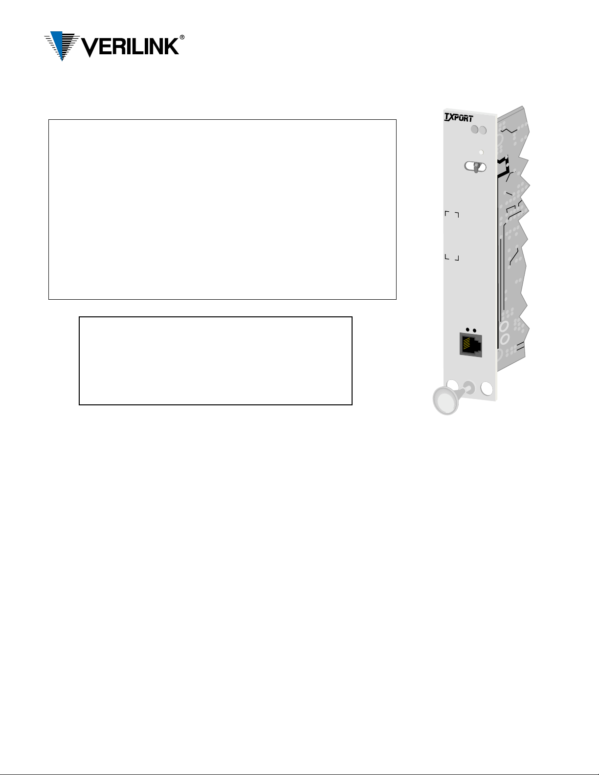
Front Panel Description
Status The green LED lights when the unit is powered and operating normally .The
red LED lights if an alarm exceeding thresholds is detected or another type of
unit failure exists.
ACO This yellow LED illuminate s if the Alarm Cut-Of f switc h is placed in the left
(On) position. It indicates that the alarm relay contacts are disabled.
ACO SW This switch controls the alarm relay circuitry. The left (On) position disables
the alarm relay co ntacts. The right (Off) position enables the contacts to
report alarm conditions.
Activity LEDs These two small, recessed indicators are provided to indicate activity on the
NMS port.
SUPV This 6-pin jack provides direct terminal access for con trolling the unit and
gathering performance data. It functions as PORT 1, therefore you cannot
have Port 1 and the SUPV ports active at the same time. Refer to the Port 1
tables for conf iguring the bit rate and pinout settings fo r the SUPV port.
Important Notice:
When installing the 8100A Site Controller as a rackmounted unit, it must be installed using threadforming screws with external tooth lock washers in
order to meet GR-1089 grounding requirements.
8100 A
SITE
CONTROLLER
A
C
O
S
W
S
U
P
V
S
T
A
T
U
S
A
C
O
SLIP Interface
Connection: 8-pin modular (RS-232)
Data Rate: 1.2, 2.4, 9 . 6, and 19.2 kbps
Compression: SLIP compression
Ethernet LAN Interface
Net Protocol: TCP/IP based networks
Access Method: Carrier sense multiple access with
collision detection (CSMA/CD)
Data Rate: 10 Mbps
Encoding: Manchester
Connection: Attachment Unit Interface (AUI)
DB-15 female with slide latch or
DB-15 female to 10Base-T
Compatibility: AUI connects to media attach-
ment units (MAU) for 10BASE2,
10BASE5, and 10BASE- T (200
mA maximum current)
Token Ring LAN Interface
Net Protocol: TCP/IP based networks
Data Rate: 4 or 16 Mbps
Connection: 8-pin modular
Compatibility: Type 3 unshielded twisted pair
Specifications
SNMP MIBS
MIB-II: Device identification and LAN
interface performance data. All
applicable objects are maintained.
DS1/E1: DS1/E1 network interface config-
uration and performance objects
are maintained per RFC 1406.
TxPORT: Company information and enter-
prise TRAPs
DDS: DDS equipment configuration
and maintenance objects.
Access Ports
Serial Ports: 2400, 9600, 19,200, and 38400
bps, 8 data bits, 1 stop bit, No parity
Modem Port: (optional) 14,400 bps, V.42/V .42 bis
Power
DC Power: -48 VDC (± 10%) ,230 mA max,
11 Watts, 38 BTU max.
Connection: The module unit connects to and
receives power from a 1051 chassis backplane. The standalone
unit uses a terminal block.
Alarm Contacts: 30 Volt and 1 Amp maximum
Mechanical (standalone model)
Mounting: Desktop, wall, horizontal or ver-
tical rack
Dimensions: Width - 1.72 inches (4.37 cm)
Height - 6.8 inches (17.27 cm)
Depth - 10.5 inches (26.67 cm)
Weight: 2 pounds (0.91 kg)
Environmental
Operating Temp:0° to 50° C (32° to 122° F)
Storage Temp: -20° to 85° C(-4° to 185° F)
Humidity: 95% max (non -cond ensi ng )
Industry Listings
FCC: Part 15 Subpart B, Class A
Part 68 Cert: DWEUSA -75322-FA-E
Modem: XE1414V
NRTL Cert: LR 98859
IC/CSO3: 1653 6223 A
Internet: RFC1155 (SMI)
RFC1157 (SNMP)
RFC1213 (MIB-II)
RFC1406 (DS1/E1 MIB)
RFC1055 (SLIP)
Ethernet: ISO/IEC 8802-3
Page 2
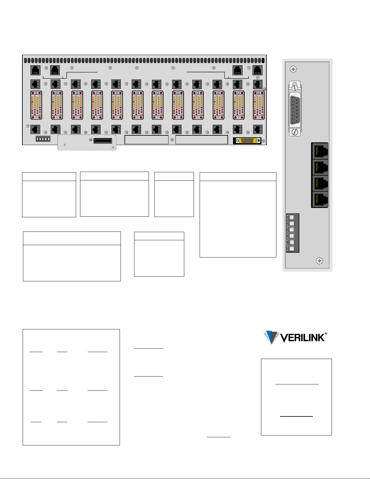
TxPORT 1051-3 Chassis Rear View
(Note: 1051-2 chassis uses DB-25 connectors on the high speed ports.
8100A Rear View
(Standalone Model)
IN
HIGH
SPEED
DTE
( B )
NMS
OUT
T1
NET
11
11
T1
NET
11
T1
NET
10
HIGH
SPEED
DTE
10
T1
NET
10
TB2
NMS A & NMS B, IN AND OUT, ARE NON-TELECOM (T1) CONNECTORS
Les portes d'entree/sortie NMS A & NMS B sont des connecteurs non-telecommunication (T1)
T1
NET
9
9
T1
NET
9
TB2 -
HIGH
SPEED
DTE
1 2 3 4 5 6
2.4 AMPS
HIGH
SPEED
DTE
HIGH
SPEED
DTE
( B )
NMS
T1
NET
12
12
T1
NET
12
1 2 3 4 5
TB1 -
Port 1 and SUPV
Pin Assignment
1 Ext. Al arm - Lead At
2 Signal Ground
3 Data Out
4 Data In
5 Signal Ground
6 Ext. Alarm - Lead B
Pin Bus IN Bus OUT
1 Not Used Not Used
2 Signal Ground Signal Ground
3 Not Used Data Out
4 Data In Not Used
5 Signal Ground Signal Ground
6 Not Used Not Used
Port 2
Pin Assignment
1 Not Used Not Used Control Out
2 Signal Ground Not Used Signal Ground
3 Data Out Telco Tip Data Out
4 Data In Telco Ring Data In
5 Signal Ground Not Used Signal Ground
6 Not Used Not Used Control In
Internal
Modem
SLIP
T1
NET
8
8
T1
NET
8
NMS
T1
NET
7
HIGH
SPEED
DTE
TB1
7
T1
NET
7
1 - EXT CLK
2 - EXT CLK
3 - ALARM RING
HIGH
SPEED
DTE
6
Power/Alarm
Pin Assignment
1 48 VDC Return (+)
2 Signal Ground
3 48 VDC (-)
4 Frame Ground
5 Alarm Contact
6 Alarm Common
4 - ALARM TIP
5 - SIG GND
HIGH
SPEED
DTE
T1
NET
5
5
T1
NET
5
T1
NET
6
T1
NET
6
Token Ring
Pin Assignment
1Not Used
2Not Used
3Data Out (-)
4 Data In (+)
5 Data In (-)
6 Data Out (+)
( A )
NMS
OUT
T1
NET
2
HIGH
SPEED
2
NET
DTE
T1
2
ENET
HIGH
SPEED
DTE
1 - +48V RTN ( B )
TB2
2 - FRAME GND
3 - -48V IN ( B )
( A )
NMS
IN
T1
NET
4
4
T1
NET
4
T1
NET
3
HIGH
SPEED
DTE
3
T1
NET
3
4 - -48V IN ( A )
5 - SIG GND
6 - +48V RTN ( A )
HIGH
SPEED
DTE
Ethernet
Pin Circuit ENET
3
DO-A
10
DO-B
11
DO-S
5
DI-A
12
DI-B
4
DI -S
2
CI-A
9
CI-B
1
CI-S
6 VC Voltage Common
13 VP Voltage Plus
14 VS Voltage Shield
Shell PG Protective Ground
SUPV and Port 1 are identical ports. You
cannot use both ports at the same time.
You must use either SUPV or Port 1.
Data Out (A)
Data Out (B)
Circuit Shield
Data In (A)
Data In (B)
Circuit Shield
Control In (A)
Control In (B)
Circuit Shield
(Conductive Shell)
T1
NET
1
1
T1
NET
1
19
ENET
815
1
NMS IN
1
6
NMS OUT
1
6
PORT 1
1
6
PORT 2
1
1
1- 48V RTN
2- GROUND
3- 48V DC
4- FRAME
5- ALM RING
6- ALM TIP
6
48VDC
Switch S1
S1-1 S1-2 TERM 1 Bit Rate
Open Open 38400 bps
Closed
Open Closed 9600 bps
Closed Closed 2400 bps
S1-3 S1-4 TERM 2 Bit Rate
Open Open 38400 bps
Closed
Open Closed 9600 bps
Closed Closed 2400 bps
S1-5 S1-6 NMS Bit Rate
Open
Closed Open 9600 bps
Open Closed 2400 bps
Closed Closed 1200 bps
Open 19200 bps
Open 19200 bps
Open 19200 bps
S1-7: Enables the forcing of a control board Flash
download on power-up.
Open - Normal
Closed - Forc ed Downloa d
S1-8: Enables the forcing of a Maintenance Reset on
power Open.
Open - Normal
Closed - Maintenance Reset
Jumper J1
Normally Open (NO) - Pins 1 and 2
Normally Closed (NC) - Pins 2 and 3
Factory default settings are shown underlined.
(formerly TxPORT)
127 Jetplex Circle
Madison, A la ba m a 35758
Technical Support
800-285-2755
205-772-3770
support@verilink.com
Returns/RMA
800-285-2755, ext. 2282
 Loading...