

Page 1
Verilink® 8000 Series
81xx/82xx/83xx/85xx
Reference Man ua l
April 2006
34-00339.C
i
Page 2

8104, 8108, 810 4s, 8108s, 8504, 8508, 8504s, 8508s
Copyright Notice
Trademarks Verilink
Documentation Disclaimer
Copyright © 2004 Verilink Corporation. All rights reserved. No part of this publication may be
reproduced, transmitted, transcribed, stored in a retrieval system, or translated into any language
in any form by any means without the writ ten permission of Veri link.
Manual Reorder # 34 -00339.C
April 2006
®
is a registered trademark of the Verilink Corporation.
All other brand and product names used herein are trademarks or registered trademarks of their
respective manufacturers.
This document does not create any express or implied warranty about Verilink or about its products or services. Verilink’s sole warranty is contained in its product warranty. The end-user documentation is shipped with Verilink’s products and constitutes the sole specificat ions referred to
in the pro duc t war ran ty. Ve rili nk ha s mad e reas ona ble effor ts to ve rify tha t the in for mat ion contained herein is accurate, but Verilink assumes no responsibility for its use or for any infringement of patents or other rights of third parties that may result. The customer is solely
responsibl e for verifying the sui tability of Verilink’s products for its use. Specifications are subject to change without notice.
Warranty Verilink's product warranty is included at the back of this d ocument. FCC Requirements This equipment has been tested and found to comply with the limits for a Class A digital device
pursuant to Part 15 of the FCC Rules. These limits are designed to provide reasonable protection
against harmful interference when the equipment is operated in a commercial environment.
Operat ion of this eq ui p m en t in a re si dential are a i s lik e ly to cau s e h ar m fu l in te rferenc e , in which
case the user is required to correct the interference at the user’s own expense.
This equipment generates, uses, and can radiate radio frequency energy, and, if not installed and
used in accordance with the instruction manual, may cause harmful interference to radio communications. However, there is no guarantee that interference will not occur in a particular
installation. If this equi pment does cause harmful interference to radio or television reception
(which can be determined by turning the equipment off and on), the user is encouraged to try to
correc t the interference by taking one or more of the following measures:
• Reorient or relocate the receiving antenna
• Increase the separation between the equipment and receiver
• Plug the equipment into an outlet on a circuit different from that to which the receiver is currently connected
• Consult the dealer or an experienced radio/TV technician for help
This device must also accept any interference received, including interference that may cause
undesired operation.
ii 8000 Series
WARNING: The 8108 and 8508 are to be used only with a certified Class 2 power supply.
See Appendix B.
WARNING: Changes or modifications to this unit not expressly approved by the party
responsible for compliance could void the user’s authority to operate the
equipment.
Page 3

The 8x08 complies with Part 68 of the FCC Rules and the requirements adopted by the ACTA.
On the bottom of the 8x08 unit is a label tha t contains, among other inform ation, a product identifier in the format of US:GICDDNANNE8x08. If requested, this number must be provided to
the telephone company.
1 All direct connections to network lines must be made using standard plugs and jacks
(compliant with Part 68 and the requirements adopted by the ACTA). A compliant telephone
cord with a modular plug is provided with this product. It is designed to be connected to a
compatible modular jack that is also compliant. See installation instructions for details. The
table below present s a list of applicable registration jack USOCs and facility interface codes
(FIC). These are required when ordering service from the telco.
IAD Port ID REN/SOC FIC USOC
8108 ADSL 0.0B RJ-11C
8508 SHDSL 0.0B RJ-11C
2 If the unit appears to be malfunctioning, it should be disconnected from the network lines
until the source of trouble is determined to be your equipment or the telephone line. If your
equipment needs repair, it should not be reconnected until it is repaired.
3 If your telephone equipment causes harm to the t elephone network, the telephone company
may discontinue your service temporarily. If possible, they will notify you in advance.
However, if advance notice is not practical, you will be notified as soon as possible. You will
be infor med of yo ur rig ht to fil e a comp laint wit h the FC C.
4 Your telephone company may make changes to its facilities, equipment, operations, or
procedures that could affect the proper funct ioning of your equipment. If they do, you will
be notified in advance so you can have the opportunity t o maintain uninterrupted telephone
service.
5 If you experience trouble with the 8108/8508 units, please contact Verilink for information
on obtaining service or repairs (refer to “Support from Verilink” on page xxvii). The
telephone company may ask that you disconnect this equipment from the network until the
problem has been corrected or until you are sure the equipment is not malfunctioning. No
user servi ceable parts are contained i n this equipment. This equipment may not be used for
coin service provided by the telephone company. Connection to party lines is subject to state
tariffs. Contact the state Public Utilities Commission or Corporation for information. Do not
attempt to repair this equipment yourself.
Canadian Emissions Requirements
This digital apparatus does not exceed the Class A limits for radio noise emissions from digital
apparatus set out in the Radio Interference Regulations of the Canadian Department of Communications.
Le présent appareil numérique n’émet pas de bruits radioélectriques dépassant les limites applicables aux appareils numériques (de la class A) prescrites dans le Règlement sur le brouillage
radioélectrique edicté par le min istère des Communications du Canada.
Safety P recauti ons When handl ing this equipment , follow these basic safety precautions to reduce the risk of elec-
tric shock and injury:
• Follow all warnings and instructions marked on the product and in the manual.
• Unplug the hardware from the wall outlet before cleaning. Do not use liquid cleaners or aerosol cleaners. Use a slightly damp cloth for cleaning.
• Do not place this product on an unstable cart, stand, or table. It may fall, causing seri ous damage to
the product.
• Slots in the unit are provided for ventilation to protect it from overheating. These openings must not
be blocked or covered. Never place this product near a radiator or heat register.
• This product should be operated only from the type of power source indicated on the marking label
and manual. If you are unsure of the type of power supply you are using, consult your dealer or local
power company.
• Do not allow anything to rest on the power cord. Do not locate this product where the cord interferes
with the free movement of people.
iii
Page 4

• Do not overload wall outlets and extension cords, as this can result in fire or electric shock.
• Never push objects of any kind into the unit. They may touch dangerous voltage points or short out
parts that could result in fire or electric shock. Never spill liquid of any kind on this equipment.
• Unplug the equipment from the wall outlet and refer servicing to qualified service personnel under the
following conditions:
• When the power supply cord or plug is damaged or frayed
• If liquid has been spilled into the product
• If the product has been exposed to rain or water
• If the product has been dropped or if the housing has been damaged
• To reduce the risk of electrical shock, do not remove the cover from the unit or external power supply.
There are no user-serviceable parts inside this unit. Contact qualified Verilink service personnel.
iv 8000 Series
Page 5

8208, 8208s, 83 04, 8308, 8304s, 83 08s
Copyright Notice
Trademarks Verilink
Documentation Disclaimer
Copyright © 2004 Verilink Corporation. All rights reserved. No part of this publication may be
reproduced, transmitted, transcribed, stored i n a retrieval system, or translated into any language
in any form by any means without the writ ten permission of Verilink.
Manual Reorder # 34 -00339.C
March 2006
®
is a registered trademark of the Verilink Corporation.
All other brand and product names used herein are trademarks or registered trademarks of their
respective manufacturers.
This document does not create any express or implied warranty about Verilink or about its products or services. Verilink’s sole warranty is contained in its product warranty. The end-user documentation is shipped with Verilink’s products and constitutes the sole specificat ions referred to
in the pro duc t war ran ty. Ve rili nk ha s mad e reas ona ble effor ts to ve rify tha t the in for mat ion contained herein is accurate, but Verilink assumes no responsibility for its use or for any infringement of patents or other rights of third parties that may result. The customer is solely
responsibl e for verifying the sui tability of Verilink’s products for its use. Specifications are subject to change without notice.
Warranty Verilink's product warranty is included at the back of this d ocument. FCC Requirements This equipment has been tested and found to comply with the limits for a Class A digital device
pursuant to Part 15 of the FCC Rules. These limits are designed to provide reasonable protection
against harmful interference when the equipment is operated in a commercial environment.
Operat ion of this eq ui p m en t in a re si dential are a i s lik e ly to cau s e h ar m fu l in te rferenc e , in which
case the user is required to correct the interference at the user’s own expense.
This equipment generates, uses, and can radiate radio frequency energy, and, if not installed and
used in accordance with the instruction manual, may cause harmful interference to radio communications. However, there is no guarantee that interference will not occur in a particular
installation. If this equi pment does cause harmful interference to radio or television reception
(which can be determined by turning the equipment off and on), the user is encouraged to try to
correc t the interference by taking one or more of the following measures:
• Reorient or relocate the receiving antenna
• Increase the separation between the equipment and receiver
• Plug the equipment into an outlet on a circuit different from that to which the receiver is currently connected
• Consult the dealer or an experienced radio/TV technician for help
This device must also accept any interference received, including interference that may cause
undesired operation.
WARNING: The 8208 is for use only with a certified Class 2 power supply. See Appendix B.
WARNING: Changes or modifications to this unit not expressly approved by the party
responsible for compliance could void the user’s authority to operate the
equipment.
v
Page 6

The 8208 complies with Part 68 of the FCC Rules and the requirements adopted by the ACTA.
On the bottom of the 8208 unit is a label tha t contains, among other inform ation, a product identifier in the format of US:GICDDNANNE8208. If requested, this number must be provided to
the telephone company.
1 All direct connections to network lines must be made using standard plugs and jacks
(compliant with Part 68 and the requirements adopted by the ACTA). A compliant telephone
cord with a modular plug is provided with this product. It is designed to be connected to a
compatible modular jack that is also compliant. See installation instructions for details. The
table below present s a list of applicable registration jack USOCs and facility interface codes
(FIC). These are required when ordering service from the telco.
IAD Port ID REN/SOC FIC USOC
8208 1.544 Mbps SF
1.544 Mbps SF, B8ZS
1.544 Mbps ANSI ESF
1.544 Mbps ANSI ESF, B8ZS
6.0N 04DU9-BN
RJ-48C jack
04DU9- DN
04DU9- 1KN
04DU9 -1SN
8308 SDSL 0.0B RJ-11C
2 If the unit appears to be malfunctioning, it should be disconnected from the network lines
until the source of trouble is determined to be your equipment or the telephone line. If your
equipment needs repair, it should not be reconnected until it is repaired.
3 If your telephone equipment causes harm to the t elephone network, the telephone company
may discontinue your service temporarily. If possible, they will notify you in advance.
However, if advance notice is not practical, you will be notified as soon as possible. You will
be infor med of yo ur rig ht to fil e a comp laint wit h the FC C.
4 Your telephone company may make changes to its facilities, equipment, operations, or
procedures that could affect the proper funct ioning of your equipment. If they do, you will
be notified in advance so you can have the opportunity t o maintain uninterrupted telephone
service.
5 If you experience trouble with the 8208/8308 units, please contact Verilink for information
on obtaining service or repairs (refer to “Support from Verilink” on page xxvii). The
telephone company may ask that you disconnect this equipment from the network until the
problem has been corrected or until you are sure the equipment is not malfunctioning. No
user servi ceable parts are contained i n this equipment. This equipment may not be used for
coin service provided by the telephone company. Connection to party lines is subject to state
tariffs. Contact the state Public Utilities Commission or Corporation for information. Do not
attempt to repair this equipment yourself.
Canadian Emissions Requirements
This digital apparatus does not exceed the Class A limits for radio noise emissions from digital
apparatus set out in the Radio Interference Regulations of the Canadian Department of Communications.
Le présent appareil numérique n’émet pas de bruits radioélectriques dépassant les limites applicables aux appareils numériques (de la class A) prescrites dans le Règlement sur le brouillage
radioélectrique edicté par le min istère des Communications du Canada.
Safety P recauti ons When handl ing this equipment , follow these basic safety precautions to reduce the risk of elec-
tric shock and injury:
• Follow all warnings and instructions marked on the product and in the manual.
• Unplug the hardware from the wall outlet before cleaning. Do not use liquid cleaners or aerosol cleaners. Use a slightly damp cloth for cleaning.
• Do not place this product on an unstable cart, stand, or table. It may fall, causing seri ous damage to
the product.
• Slots in the unit are provided for ventilation to protect it from overheating. These openings must not
be blocked or covered. Never place this product near a radiator or heat register.
vi 8000 Series
Page 7

• This product should be operated only from the type of power source indicated on the marking label
and manual. If you are unsure of the type of power supply you are using, consult your dealer or local
power company.
• Do not allow anything to rest on the power cord. Do not locate this product where the cord interferes
with the free movement of people.
• Do not overload wall outlets and extension cords, as this can result in fire or electric shock.
• Never push objects of any kind into the unit. They may touch dangerous voltage points or short out
parts that could result in fire or electric shock. Never spill liquid of any kind on this equipment.
• Unplug the equipment from the wall outlet and refer servicing to qualified service personnel under the
following conditions:
• When the power supply cord or plug is damaged or frayed
• If liquid has been spilled into the product
• If the product has been exposed to rain or water
• If the product has been dropped or if the housing has been damaged
• To reduce the risk of electrical shock, do not remove the cover from the unit or external power supply.
There are no user-serviceable parts inside this unit. Contact qualified Verilink service personnel.
vii
Page 8

8216s, 8224s, 8316s, 8324s, 8512s, 8516s, 8524s
Copyright Notice
Trademarks Verilink
Documentation Disclaimer
Copyright © 2004 Verilink Corporation. All rights reserved. No part of this publication may be
reproduced, transmitted, transcribed, stored i n a retrieval system, or translated into any language
in any form by any means without the writ ten permission of Verilink.
Manual Reorder # 34 -00339.C
March 2006
®
is a registered trademark of the Verilink Corporation.
All other brand and product names used herein are trademarks or registered trademarks of their
respective manufacturers.
This document does not create any express or implied warranty about Verilink or about its products or services. Verilink’s sole warranty is contained in its product warranty. The end-user documentation is shipped with Verilink’s products and constitutes the sole specificat ions referred to
in the pro duc t war ran ty. Ve rili nk ha s mad e reas ona ble effor ts to ve rify tha t the in for mat ion contained herein is accurate, but Verilink assumes no responsibility for its use or for any infringement of patents or other rights of third parties that may result. The customer is solely
responsibl e for verifying the sui tability of Verilink’s products for its use. Specifications are subject to change without notice.
Warranty Verilink's product warranty is included at the back of this d ocument. FCC Requirements This equipment has been tested and found to comply with the limits for a Class A digital device,
except for th e 8 512 , wh ich comp lies with Cl ass B l imi ts , pursu ant to P art 1 5 of the F CC R ule s.
These limits are designed to provide reasonable protection against harmful interference when
the equi pment i s oper ated in a comm ercia l envir onmen t. Ope ration o f this e quipme nt in a r esidential area is likely to cause harmful interference, in which case the user is required to correct
the interference at the user’s own expense.
This equipment generates, uses, and can radiate radio frequency energy, and, if not installed and
used in accordance with the instruction manual, may cause harmful interference to radio communications. However, there is no guarantee that interference will not occur in a particular
installation. If this equi pment does cause harmful interference to radio or television reception
(which can be determined by turning the equipment off and on), the user is encouraged to try to
correc t the interference by taking one or more of the following measures:
• Reorient or relocate the receiving antenna
• Increase the separation between the equipment and receiver
• Plug the equipment into an outlet on a circuit different from that to which the receiver is currently connected
• Consult the dealer or an experienced radio/TV technician for help
This device must also accept any interference received, including interference that may cause
undesired operation.
viii 8000 Series
WARNING: The 8224/8324 and 8524 are for use onl y w ith a c er tif ied Cl ass 2 pow er s upp l y.
See Appendix B.
WARNING: Changes or modifications to this unit not expressly approved by the party
responsible for compliance could void the user’s authority to operate the
equipment.
The NetEngine 8224/8524 complies with Part 68 of the FCC Rules and the requirements
adopted by the ACTA. On the bottom of the 8000 Series units is a label that contains, among
other information, a product identifier in the format of US:GICDDNAN85xx or
US:GICDDNAN82xx. If requested, thi s number must be provided to the telephone company.
Page 9

1 All direct connections to network lines must be made using standard plugs and jacks
(compliant with Part 68 and the requirements adopted by the ACTA). A compliant telephone
cord with a modular plug is provided with this product. It is designed to be connected to a
compatible modular jack that is also compliant. See installation instructions for details. The
table below present s a list of applicable registration jack USOCs and facility interface codes
(FIC). These are required when ordering service from the telco.
IAD Port ID REN/SOC FIC USOC
8224s 1.544 Mbps SF
1.544 Mbps SF, B8ZS
1.544 Mbps ANSI ESF
1.544 Mbps ANSI ESF, B8ZS
6.0N 04DU9-BN
RJ-48C jack
04DU9- DN
04DU9- 1KN
04DU9 -1SN
8324s SDSL 0.0B RJ-11C
8524s SHDSL 0.0B RJ-11C
2 If the unit appears to be malfunctioning, it should be disconnected from the network lines
until the source of trouble is determined to be your equipment or the telephone line. If your
equipment needs repair, it should not be reconnected until it is repaired.
3 If your telephone equipment causes harm to the t elephone network, the telephone company
may discontinue your service temporarily. If possible, they will notify you in advance.
However, if advance notice is not practical, you will be notified as soon as possible. You will
be infor med of yo ur rig ht to fil e a comp laint wit h the FC C.
4 Your telephone company may make changes to its facilities, equipment, operations, or
procedures that could affect the proper funct ioning of your equipment. If they do, you will
be notified in advance so you can have the opportunity t o maintain uninterrupted telephone
service.
5 If you experience trouble with the 8000 Series units, please contact Verilink for information
on obtaining service or repairs (refer to “Support from Verilink” on page xxvii). The
telephone company may ask that you disconnect this equipment from the network until the
problem has been corrected or until you are sure the equipment is not malfunctioning. No
user servi ceable parts are contained i n this equipment. This equipment may not be used for
coin service provided by the telephone company. Connection to party lines is subject to state
tariffs. Contact the state Public Utilities Commission or Corporation for information. Do not
attempt to repair this equipment yourself.
Canadian Emissions Requirements
This digital apparatus does not exceed the Class A limits for radio noise emissions from digital
apparatus set out in the Radio Interference Regulations of the Canadian Department of Communications.
Le présent appareil numérique n’émet pas de bruits radioélectriques dépassant les limites applicables aux appareils numériques (de la class A) prescrites dans le Règlement sur le brouillage
radioélectrique edicté par le min istère des Communications du Canada.
Safety P recauti ons When handl ing this equipment , follow these basic safety precautions to reduce the risk of elec-
tric shock and injury:
• Follow all warnings and instructions marked on the product and in the manual.
• Unplug the hardware from the wall outlet before cleaning. Do not use liquid cleaners or aerosol cleaners. Use a slightly damp cloth for cleaning.
• Do not place this product on an unstable cart, stand, or table. It may fall, causing seri ous damage to
the product.
• Slots in the unit are provided for ventilation to protect it from overheating. These openings must not
be blocked or covered. Never place this product near a radiator or heat register.
• This product should be operated only from the type of power source indicated on the marking label
and manual. If you are unsure of the type of power supply you are using, consult your dealer or local
power company.
• Do not allow anything to rest on the power cord. Do not locate this product where the cord interferes
with the free movement of people.
ix
Page 10

• Do not overload wall outlets and extension cords, as this can result in fire or electric shock.
• Never push objects of any kind into the unit. They may touch dangerous voltage points or short out
parts that could result in fire or electric shock. Never spill liquid of any kind on this equipment.
• Unplug the equipment from the wall outlet and refer servicing to qualified service personnel under the
following conditions:
• When the power supply cord or plug is damaged or frayed
• If liquid has been spilled into the product
• If the product has been exposed to rain or water
• If the product has been dropped or if the housing has been damaged
• To reduce the risk of electrical shock, do not remove the cover from the unit or external power supply.
There are no user-serviceable parts inside this unit. Contact qualified Verilink service personnel.
x 8000 Series
Page 11

Table of Contents
Preface
About th i s Ma n u al ....... .. ... .................... .. .. ..........................................................................................xxv
Products Covered by this Manual ................... ........... ...................... ................... ........... ..............xxv
Manual Organization ....................................................................................................................xxv
Typographic Conventions .......................................................................................................... xxvi
Customer Service and Technical Support ........... ................... ...................... ........... ........... ............... xxvi
Support from Your Network Supplier ....................................................................................... xxvii
Support from Verilink .......... ........... ........... ........... ................... ........... ........... ........... ................ xxvii
Telephone ........................................................................................................................... xxvii
E-mail ................................................................................................................................. xxvii
Intern et ..... ......... ....... ......... ......... ......... ....... ......... ......... ......... ....... ......... ......... ......... ............ xxvii
Returning a Unit to Verilink ...........................................................................................................xxviii
Chapter 1 Introduction
Interfaces an d Feat u re s of the
Low POTS Port Platform Architecture ............................................................................................... 1-2
Low POTS Port Platform Architecture ........................................................................................1-2
Low POTS Port Features .............................................................................................................1-2
Low POTS Port Front Panel LED Status Indicators ............................................................. 1-3
Low POTS Port Rear Panel Connectors ................................................................................ 1-4
Interfaces an d Feat u re s of the
High PO T S P or t Pl at f o r m A rc h it e ct u r e ....... ....................................................................................... 1-6
High PO T S P or t Pl at f o r m A rc h it e ct u r e ...... ... .. ............................................................................ 1-6
High PO T S P or t Feature s .... .. ....... .. .. ............................................................................................ 1-6
High PO T S P or t Front Pan el LED S ta tu s In d ic a t o rs ............................................................. 1 - 7
High POTS Port Rear Panel Connectors . ..............................................................................1-8
Chapter 2 Quick Start Guide
Unpacking the IAD ............................................................................................................................. 2-1
Installing the IAD ............................................................................................................................... 2-2
AC Power and Uninterruptible Power Supply .............................................................................2-2
Clearance Requirements ...............................................................................................................2-2
Wirin g Requir e ments .......... ......................................................................................................... 2-2
Connecting the IAD Via a Terminal Emulator .......... ........... ........... ................... ........... ........... ...2-2
Connecting the IAD to a PC ................ ........... ................... ........... ........... ........... ........... ........2-3
Loggin g in vi a a T e rminal E mu l a t i o n Pro g r am ..................................................................... 2-4
Settin g th e Et h er n et Port IP Addres s ............................................................................................ 2-6
Setting the WAN Port IP Address ................................................................................................2-8
Resetting the IAD ......................................................................................................................... 2-8
Connecting via Telnet ........ ........... ........... ...................... ................... ........... ........... ........... .......... 2-9
xiii
Page 12

Running Telnet ...................................................................................................................... 2-9
Basic IA D C o n fi g u ra t i o n .... ....................................................................................................... 2-11
Connecting LAN, WAN, and Telephones ............... ........... ........... ........... ................... ........... ...2-11
Ethernet LAN Connection ............ ................... ........... ........... ........... ........... ................... .....2-12
WAN Co n n e ct i o n s ... .. .......................................................................................................... 2-12
Telephone Connections ....................... .............................. ........... ........... ........... ........... ......2-12
Life Line Connection ............ ........... ........... ........... ........... ................... ........... ........... ..........2-12
USI Connection .......................... ........... ................... ........... ........... ........... ........... .......... .....2-13
Confir m i n g Proper Se tu p . ... ....................................................................................................... 2-13
Chapter 3 Administration
IAD Security ....... .. .............................................................................................................................. 3-1
Passwo r d Co n f ig u r at i o n M en u ..................................................................................................... 3-2
Change User ID .....................................................................................................................3-3
Change User Password .......................................................................................................... 3-4
RADI U S Se rver Set t in g s .... ... ................................................................................................ 3-4
Settin g U p SN MP . .............................................................................................................................. 3-5
SNMP Co n f i g u rat i o n M en u ......................................................................................................... 3-6
Enable/Disable SNMP via IP ................................................................................................ 3-7
Enable/Disable SNMP via EOC ............................................................................................ 3-7
Enable SNMP via Both IP and EOC ..................................................................................... 3-7
Disable SNMP via Both IP and EOC .................................................................................... 3-7
Config u r e Sy s t e m C o nta ct .. .............. .. .. ................................................................................. 3-7
Config u r e Sy s t e m Na m e ... .. ................................................................................................... 3-8
Config u r e Sy s t e m Lo c a ti o n ..... .............................................................................................. 3 -8
Config u r e SN MP Com munit y ... ............................................................................................ 3-8
Config u r e SN MP Trap H o s t IP A d d res s ..... .. ........................................................................ 3 - 9
Enabl e / D isable SNMP Tra ps v ia EO C .................................................................................. 3-9
Config u r e Resta rt Trap Maximum Del a y ...... ... .................... .. .. ............................................. 3-9
Defining Different SNMP Version 3 Categories ................................................................... 3-9
LAN Configuration Menu ................................................................................................................ 3-11
Establishing LAN Speed and Duplex Mode .............................................................................. 3-11
Upgrading the System ....................................................................................................................... 3-11
Using T F T P Servers vi a LAN or WAN ............................... .. ... ................................................. 3-12
Copying the Source Files ...........................................................................................................3-12
Upgrading via TFTP .................................................................................................................. 3-12
Verify i n g th e U p gr a d e .. .............................................................................................................. 3-13
Utiliti es M e n u ..... .. ............................................................................................................................ 3-13
Ping Utility ................................................................................................................................. 3-14
Trace Route ................................................................................................................................ 3-14
Configure Console Baud Rate ....................................................................................................3-14
Config u r e Co n s o l e Timeou t ............. .. ... .....................................................................................3-15
Reset o r R el o ad A C O S fr o m F L A S H ........................................................................................ 3 -1 5
Set Sys t em Defau l ts ....... .. ....... .. ... .............................................................................................. 3-16
Save System Settings as Defaults .............................................................................................. 3-16
Displa y E ve n t L o g ... ................................................................................................................... 3-17
Clear “Last Reset Reason” ......................................................................................................... 3-17
xiv 8000 Series
Page 13

Time M en u . .. .. ............................................................................................................................3-17
NTP Ser v e r M e n u ...... ........................................................................................ .. ... .............3-18
Time Zo n e Me n u ... ..............................................................................................................3-18
Displa y Co n fi g u r at i o n Fi l e ........................ .. ... ............................................................................3-19
File System Menu ...................................................................................................................... 3-19
Directory of all Files ............................................................................................................ 3-19
Type File .............................................................................................................................. 3-20
Copy File .................. ........... ................... ........... ........... ........... ........... ................... .............. 3-20
Rename File ......................................................................................................................... 3-20
Delet e Fi l e ... .. ....................................................................................................................... 3-20
Format File System Drive .................................................................................................... 3-21
Space Left in File System .................................................................................................... 3-21
File Transfer Menu ..................................................................................................................... 3-21
Load Boot ROM ..................................................................................................................3-21
Update ACOS [acos.bin] ..................................................................................................... 3-22
Update Entire System .......................................................................................................... 3-22
File Transfer Utilities ........................................................................................................... 3-22
TFTP Server Menu .............................................................................................................. 3-23
Chapter 4 Configuration
Introduction ......................................................................................................................................... 4-1
Manag i n g Co n f i g u rat i o n Fil e s ..... .. .. ......................................................................................... .......... 4-1
WAN Co n f i g u rat i on ........................................................................................................................... 4-2
Basic W A N Se t u p Ta s ks ....... .. ........................................................................................ .. .. .........4-2
Setting the WAN Port IP Address ................................................................................................4-3
Ident if y in g the WAN In t er face and Da t al in k Pr o t o co l .... .. .. ........................................................ 4-4
WAN Co n f i g u rat i o n Menu ... .. .. ................................................................................................... 4-5
Config u r e Ph y s i c al I n te rf ace - SDSL . .............. .. .. ................................................................. 4-7
Quick Configuration for SDSL WAN ................................................................................. 4-10
Config u r e Ph y s i c al I n te rf ace - T1/E 1 . ................................................................................. 4 -1 1
Config u r e Ph y s i c al I n te rf ace - ADS L ................................................................................. 4-19
Config u r e Ph y s i c al I n te rf ace - SHD SL ............................................................................... 4-20
Config u r e Ph y s i c al I n te rf ace - USI .... .. ... ............................................................................ 4-21
Config u r e D a t al i n k Pr o toc o l .. .............................................................................................. 4- 2 2
Config u r e ATM PVCs .. ............. .. ... ..................................................................................... 4-24
Config u r e A T M Option s .... ... .. ....... .. .. ................................................................................. 4- 3 0
Config u r e D L C I s ................................................................................................................. 4-31
Configure Frame Relay Options .......................................................................................... 4-34
Router Co n fi g u r at i o n ........................................................................................................................4-38
Basic Ro u t er Setup T as k s .... .......................................................................................................4-38
Router Co n fi g u r at i o n Me n u .. ..................................................................................................... 4-39
Config u r e Po r t IP Addres s ................................................................................................... 4- 40
Unconfigure Port IP Address ...............................................................................................4-41
Config u r e Po r t Maximu m T r an s missio n Un i t (MTU) .... ... ................................................. 4-42
Config u r e Po r t T CP MSS Ad j u stment . ... .. .................................. .. .. .................................... 4-42
Add/Remove a Static or Source Route ................................................................................ 4-42
Enabl e / D isable RI P .............................................................................................................. 4-44
xv
Page 14

Config u r e RIP Vers i o n b y Port ........................................................................................... 4-45
Config u r e RIP Poi son e d Revers e b y Port ...... ...................................................................... 4-45
Config u r e D N S Cl i en t .... .. .. ................................................................................................. 4-46
Config u r e D H C P Cl ient .... .. ........................... ... .. ................................................................. 4-47
Config u r e D H C P Re l ay ....................................................................................................... 4 -4 7
Configure Telnet Server Port ............................................................................................... 4-48
Config u r e I P Qo S ...... ... .. ............. ... .. ................................................................................... 4-49
Configure IP Filtering ..........................................................................................................4-49
Config u r e I P Header Co mpress io n (I P H C ) ... ........................... ... .. ...................................... 4-51
Config u r e L A N I P Br o ad cast Des t i n at io n . .......................................................................... 4-51
Config u r e D o m a in N ame .... ... .............................................................................................. 4- 5 1
Config u r e H o s t N ame ... .. ..................................................................................................... 4-52
Remov e Host an d Domain Names .. .. .. ................................................................................. 4- 5 2
Displa y Ro u t e Table ............................................................................................................4-52
Bridge Co n fi g u r at i o n ........................................................................................................................4-53
Basic Bridge Se tu p T as k s .... .......................................................................................................4-53
Bridge Co n fi g u r at i o n Me n u .. ..................................................................................................... 4-54
Enabl in g an d Di s ab l in g Br id g i ng ... .. .. ................................................................................. 4- 5 5
IP Over B r id g i n g ... .. .. .......................................................................................................... 4-55
Enabl e / D isable Br id g i n g Glo b a l ly ....................................................................................... 4- 5 6
Enable/Disable Bridging by Port ......................................................................................... 4-56
Bridge A g ing Timer ... ..........................................................................................................4-57
Enabl in g an d Di s ab l in g Sp a n n in g T r ee ............................................................................... 4-57
Enabl e / D isable Spannin g Tr ee G lob ally . ............................................................................ 4 -5 7
Enabl e / D isable Spannin g Tr ee b y Po rt ................................................................................ 4- 5 8
Config u r e Sp annin g Tree Brid g e Pr i o ri t y ........................................................................... 4-58
Config u r e Sp annin g Tree Port Pri o r i ty ................................................................................ 4-58
Config u r e Sp annin g Tree Hello T im e ..... ............................................................................ 4-59
Config u r e Sp annin g Tree Maxi m u m A g e ........................................................................... 4-5 9
Config u r e Sp annin g Tree Forw a r d Del a y . .. .. ...................................................................... 4 -5 9
Config u r e Sp annin g Tree Path Co s t ..... ............................................................................... 4-60
Delet e Br i d g e Fo r w a r d i ng D a t ab as e Entry .......................................................................... 4 -6 0
Voice Pat h Co n f i g ur a t ion . .. .. ............................................................................................................ 4-60
Basic V o i ce Pat h S et u p Ta sk s ... ................................................................................................. 4-61
Voice Co n fi g u r at i o n M e n u ........................................................................................................ 4-61
Set Voice Gat ew ay ....... .. .....................................................................................................4-61
Set Jitt er D el a y .. ... ................................................................................................................ 4-79
Voice Po rt Se t t ing s ....... .. .....................................................................................................4-79
Display Compander Mode (µ-law, A-l a w ) .... .................................. .. ... ............................... 4-84
Set Country Mode ................................................................................................................4-85
Set DuS L IC Mode . .. ............................................................................................................ 4-85
Enable/Disable G726 Annex A ...........................................................................................4-85
Interworking Connections ................................................................................................................ 4-85
FRF.5 ... .. ..... .... ..... .. ..... .... ..... .. .... ..... .. ..... .... ..... .. .... ..... .... ... .... ..... .... .. ..... .... ..... .. ..... .... .................. 4-87
FRF.8 ... .. ..... .... ..... .. ..... .... ..... .. .... ..... .. ..... .... ..... .. .... ..... .... ... .... ..... .... .. ..... .... ..... .. ..... .... .................. 4-88
Firew a l l Con f i g u ra t i o n ... ... ................................................................................................................4-89
Creat i n g a Fi re w a ll v ia IP Fil t er i n g an d N A T .. .......................................................................... 4- 8 9
DHCP Server Configuration ............................................................................................................. 4-90
xvi 8000 Series
Page 15

Basic DHCP Server Setup Tasks ............................................................................................... 4-90
DHCP Server Configuration Menu ............................................................................................ 4-90
Enabl e / D isable DH CP Server .. .. .. ........................................................................................ 4- 9 1
Enabl e / D isable Checking A d d it i o n al DH C P Servers .. ........................................................ 4-91
Enabl e / D isable DH CP Debu g Messag e s ..... .. ........................... ... .. ...................................... 4 - 9 1
Configure DHCP Server Parameters ................................................................................... 4-91
Config u r e D H C P Ad d ress Ra n ge Po ol ................................................................................ 4- 9 2
Config u r e D H C P Cl ient Entry . ............. ... .. .......................................................................... 4-92
Displa y D H CP Config u ration .. ............. ... .. .......................................................................... 4- 9 3
Display DHCP Server Statistics .......................................................................................... 4-94
Display DHCP Server Assigned and Unassigned Addresses .............................................. 4-95
Display DHCP Entry Details ............................................................................................... 4-95
Delete a DHCP Client Entry ................................................................................................ 4-96
Delete a DHCP Assignment Entry ...................................................................................... 4-96
Multicast Configuration .................................................................................................................... 4-96
Multicast Configuration Menu ...................................................................................................4-96
Enable/Disable Global IP Multicasting ............................................................................... 4-97
Config u r e PIM - Den se Mode by Po r t .. ... ............................................................................ 4-97
Add/C h an g e Mu l t ic a s t Rou t e So u r ce . .. ... ............................................................................ 4-97
Show IGMP Group .............................................................................................................. 4-99
Show IGMP Querier ............................................................................................................ 4-99
Show Mu l t icast Rou t i n g T ab l e .. .. ... ................................................................................... 4-100
Show PIM Neighbor ..................... ................... ........... ........... .................... ........... .............4-100
NAT Configuration .........................................................................................................................4-101
NAT Configuration Menu ....................................................................................................... 4-101
Enabl e / D isable NA T De b u g Messag e s ... .......................................................................... 4 -1 0 2
Enable/Disable NAT Translation by Port .......................................................................... 4-103
Configure NAT TCP and UDP Timeouts .......................................................................... 4-103
Configure NAT Port Range ............................................................................................... 4-103
Configure NAT Local Server Entry .................................................................................. 4-104
Configure NAT Alias Entry .............................................................................................. 4-105
Displa y N A T Statistic s ... .. .. ............................................................................................... 4-106
Displa y N A T Co nn ection T ab l e ........................................................................................ 4-1 0 7
Displa y N A T Co nn ection D et ai l s ... ................................................................................... 4-107
Displa y N A T Lo cal Serv er T a b l e ...................................................................................... 4- 1 0 8
Display NAT Alias Table .................................................................................................. 4-108
Clear NAT Statistics .......................................................................................................... 4-108
Delet e IP A d d res s f ro m N A T Tables ................................................................................ 4-109
Delet e N A T Lo cal Serv er E n try ........................................................................................ 4-10 9
Delete NAT Alias Entry .................................................................................................... 4-109
Settin g PPP Opti o n s ........................................................................................................... ............. 4-109
Settin g D erive d Ti m i n g Opt io n s .. ............. ... .. ................................................................................. 4-110
Deriv ed T im i n g Menu .... ........................................................................................................ .. 4-110
Enabl e / D isable Derived T i mi n g .................................................................... .. .. ................ 4-110
Enable/Disable Derived Timing Debug Messages ............................................................4-110
xvii
Page 16

Chap ter 5 Repo rts
Repor ts Menu .... .................................................................................................................................. 5-1
Current Configuration Report ...................................................................................................... 5-2
Network Statistics Reports ...........................................................................................................5-4
ICMP Statistics Report .......................................................................................................... 5-5
IGMP St a t i sti c s Rep o r t ..... ..................................................................................................... 5-6
IP Stati s ti cs Report ....... .. .. ......................................... .. .. ........................................................ 5-8
PIM Sta t i sti c s Rep o r t .... .. ................................................................... ... .. ............................... 5-9
TCP Statistics Report ........................................................................................................... 5-10
UDP Sta t i s tic s Rep o r t ....... ...................................................................................................5-12
Clear Network Statistics ...................................................................................................... 5-12
Interface Stat i s ti cs R e po rts .. .. ..................................................................................................... 5-13
Displa y In terface St at i st i cs ................................................................... .. .. ........................... 5-14
Displa y D L CI St at i s ti cs ....................................................................................................... 5-15
Displa y A T M PV C Stat ist ics . ................................................................... .. ... ...................... 5- 1 6
Displa y Bri d g e St at i st i cs .... ... ............................................... .. .. ........................................... 5-21
Clear Interface Statistics ......................................................................................................5-22
Media Statistics Reports ............................................................................................................. 5-22
Display Frame Relay Statistics ............................................................................................ 5-23
Displa y A T M St a t i s tic s .......................................................... .. ... ........................................ 5-24
Displa y G 7 070 ADSL St at i st i cs ( 8 1xx ) .............................................................................. 5-25
Display G2237 xDSL Statistics (85xx) ............................................................................... 5-26
Display Serial (USI) Statistics (8216s/8224s/8316s/8324s/8512s/8516s/8524s) ................ 5-27
Displa y E thernet Statistics ................................................................................................... 5-29
Displa y PO T S Statis ti c s .. .......................................................................... .. ... ...................... 5-30
Clear Media Statistics ..........................................................................................................5-31
Route T a b le Re p o rt .... .. .. ............................................................................................................ 5-31
ARP Table Report ...................................................................................................................... 5-31
Bridge Fo rward i n g Da t ab ase Rep o rt .......................................................................................... 5-32
Bridge St at u s R ep o rt .... .. ............................................................................................................ 5-32
PPP Authorization Entries Report .............................................................................................. 5-33
System Uptime Report ...............................................................................................................5-33
Memory Stati s ti cs Repor ts ......................................................................................................... 5-33
Displa y Sy s t em M e m ory Stati s ti c s . ...................................................... .. .. ........................... 5-34
Displa y K er n el T as k s Memor y Stat i s ti cs ............................................................................ 5-3 5
Tasks Run Time ......................................................................................................................... 5-35
Zero A ll St a t i sti c s .. ........................... .. ... ..................................................................................... 5-36
Chapter 6 Command Line Interface
Introduction ......................................................................................................................................... 6-1
CLI Help .......................................................................................................................................6-1
Command Line Syntax ....................................................................................................................... 6-2
Chapter 7 Troubleshooting and Diagnostics
Using the Diagnostics Menu ............................................................................................................... 7-1
xviii 8000 Series
Page 17

POTS Diagnostics ................ ........... ........... ........... ................... ........... ........... ........... ................... 7-2
Dialup T es t ...... ... .. ....... .. .. ..................................................................................................... 7-2
Hotlin e T es t ........................................................................................................................... 7-3
Ring Test ................................................................................................................................ 7-3
On/Off Hook Test .......... ........... ........... ........... ................... ........... ........... ........... ........... ........ 7-4
SDSL Diagnostics ................ ........... ........... ........... ................... ........... ........... ........... ................... 7-5
Troubleshooting the IAD .................................................................................................................... 7-5
Chapter 8 Verification
Power-up Test .....................................................................................................................................8-1
Operational Test .................................................................................................................................. 8-1
Testin g the IA D ............................................................................................................................ 8-2
Maintenance ................................................................................................................................. 8-2
Displa y i n g the Cu rr ent Con fi g u ra t i o n ... ....................................................................................... 8-2
Appendix A Menu Map
Appendix B Specifications
T1/E1 (8208/8208s) ............................................................................................................................B-1
Voice Feature s ... ...........................................................................................................................B-1
Analog Voice .........................................................................................................................B-1
Digital Voice ..........................................................................................................................B-1
Data Feature s .. ..............................................................................................................................B-2
WAN Fe a tu res ..............................................................................................................................B-2
Network Interfaces .......................................................................................................................B-2
T1 .... ....... ..... ...... ....... ..... ...... ....... ....... .... ....... ....... ....... .... ....... ....... ...... ..... ....... ...... ..................B-2
E1 .... ....... ..... ...... ....... ..... ...... ....... ....... .... ....... ....... ....... .... ....... ....... ...... ..... ....... ...... ..................B-3
T1/E1 Provisioning (8208s Only) ........... ........... ........... ........... ........... ................... ........... .....B-3
ATM ......................................................................................................................................B-3
Frame Relay ...........................................................................................................................B-3
Configuration and Management ...................................................................................................B-4
10/100 Ethernet (Managemen t or IP Gateway) ............................................ ........... ........... ...B-4
Supervisory Port ....................................................................................................................B-4
Upgra des ....... ........... ........... ............ ......... ........... ........... ........... ......... ............ ........... .............B-4
Management ..........................................................................................................................B-4
Secur i ty Featu res .................................................................................................. .. .. ....................B-4
Integ rat e d Fi rewall ... ..............................................................................................................B-4
Management Interfaces ................................................................................................................B-4
Alarms ...................................................................................................................................B-4
Diagnostics ...................................................................................................................................B-4
Enviro nmental ... ............. .............. ................................................................................................B-5
Connector Pin Assignments .........................................................................................................B-6
Console Port Pin Assignments (DB-9) ..................................................................................B-6
POTS Port Pin Assignments (RJ-11) .....................................................................................B-6
10/100Base-T Connector Pin Assignments (RJ-45) ..............................................................B-6
T1/E1 Connector Pin Assignments (RJ-48) ..........................................................................B-6
xix
Page 18

T1/E1 (8216s and 8224s) ....................................................................................................................B-7
Voice Feature s ... ...........................................................................................................................B-7
Analog Voice .........................................................................................................................B-7
Digital Voice ..........................................................................................................................B-7
Data Feature s .. ..............................................................................................................................B-7
WAN Fe a tu res ..............................................................................................................................B-8
Network Interfaces .......................................................................................................................B-8
T1 .... ....... ..... ...... ....... ..... ...... ....... ....... .... ....... ....... ....... .... ....... ....... ...... ..... ....... ...... ..................B-8
E1 .... ....... ..... ...... ....... ..... ...... ....... ....... .... ....... ....... ....... .... ....... ....... ...... ..... ....... ...... ..................B-8
T1/E1 P ro v i s io n i n g .... ... ................................................................... .. ... .................................B-9
ATM ......................................................................................................................................B-9
Frame Relay ...........................................................................................................................B-9
Universal Serial Interface (DB-25) ........................................................................................B-9
Configuration and Management ...................................................................................................B-9
10/100 Ethernet (Managemen t or IP Gateway) ............................................ ........... ........... ...B-9
Supervisory Port ..................................................................................................................B-10
Upgra des ....... ........... ........... ............ ......... ........... ........... ........... ......... ............ ........... ...........B-10
Management ........................................................................................................................B-10
Secur i ty Featu res .................................................................................................. .. .. ..................B-10
Integ rat e d Fi rewall ... ............................................................................................................B-10
Management Interfaces ..............................................................................................................B-10
Alarms .................................................................................................................................B-10
Diagnostics .................................................................................................................................B-10
Enviro nmental ... ............. .............. ..............................................................................................B-10
Industry Listings .........................................................................................................................B-11
Connector Pin Assignments .......................................................................................................B-12
Console Port Pin Assignments (DB-9) ................................................................................B-12
POTS Port Pin Assignments (RJ-21) ...................................................................................B-12
10/100Base-T Connector Pin Assignments (RJ-45) ............................................................B-12
T1/E1 Connector Pin Assignments (RJ-48) ........................................................................B-12
USI Connector Pin Assignments (RS-530, V.35) ...............................................................B-13
SDSL (8304/8304s and 8308/8308s) .......... ........... ........... ........... ........... ................... ........... ............B-14
Voice Feature s ... .........................................................................................................................B-14
Analog Voice .......................................................................................................................B-14
Digital Voice ........................................................................................................................B-14
Data Feature s .. ............................................................................................................................B-14
WAN Fe a tu res ............................................................................................................................B-15
Interfa ce .......... ................................................................................................... ..................B-15
ATM ....................................................................................................................................B-15
Frame Relay .........................................................................................................................B-15
Configuration and Management .................................................................................................B-16
10/100 Ethernet (Managemen t or IP Gateway) ............................................ ........... ........... .B-16
Supervisory Port ..................................................................................................................B-16
Upgra des ....... ........... ........... ............ ......... ........... ........... ........... ......... ............ ........... ...........B-16
Management ........................................................................................................................B-16
Secur i ty Featu res .................................................................................................. .. .. ..................B-16
Integ rat e d Fi rewall ... ............................................................................................................B-16
Management Interfaces ..............................................................................................................B-16
Alarms .................................................................................................................................B-16
Enviro nmental ... ............. .............. ..............................................................................................B-16
xx 8000 Series
Page 19

Connector Pin Assignments .......................................................................................................B-18
Console Port Pin Assignments (DB-9) ................................................................................B-18
POTS Port Pin Assignments (RJ-11) ...................................................................................B-18
10/100Base-T Connector Pin Assignments (RJ-45) ............................................................B-18
SDSL Connector Pin Assignments (RJ-11) .........................................................................B-18
SDSL (8316s and 8324s) .............. ........... ........... ................... ........... ........... ........... ........... ...............B-19
Voice Feature s ... .........................................................................................................................B-19
Analog Voice .......................................................................................................................B-19
Digital Voice ........................................................................................................................B-19
Data Feature s .. ............................................................................................................................B-19
WAN Fe a tu res ............................................................................................................................B-20
Interfa ce .......... ................................................................................................... ..................B-20
ATM ....................................................................................................................................B-20
Frame Relay .........................................................................................................................B-20
Universal Serial Interface (DB25) .......................................................................................B-21
Configuration and Management .................................................................................................B-21
10/100 Ethernet (Managemen t or IP Gateway) ............................................ ........... ........... .B-21
Supervisory Port ..................................................................................................................B-21
Upgra des ....... ........... ........... ............ ......... ........... ........... ........... ......... ............ ........... ...........B-21
Management ........................................................................................................................B-21
Secur i ty Featu res .................................................................................................. .. .. ..................B-21
Integ rat e d Fi rewall ... ............................................................................................................B-21
Management Interfaces ..............................................................................................................B-21
Alarms .................................................................................................................................B-21
Enviro nmental ... ............. .............. ..............................................................................................B-22
Connector Pin Assignments .......................................................................................................B-23
Console Port Pin Assignments (DB-9) ................................................................................B-23
POTS Port Pin Assignments (RJ-21) ...................................................................................B-23
10/100Base-T Connector Pin Assignments (RJ-45) ............................................................B-23
SDSL Connector Pin Assignments (RJ-11) .........................................................................B-23
USI Connector Pin Assignments (RS-530, V.35) ...............................................................B-23
ADSL (8104/8104s and 8108/8108s) ...............................................................................................B-25
Voice Feature s ... .........................................................................................................................B-25
Analog Voice .......................................................................................................................B-25
Digital Voice ........................................................................................................................B-25
Data Feature s .. ............................................................................................................................B-25
WAN Fe a tu res ............................................................................................................................B-26
Interfa ce .......... ................................................................................................... ..................B-26
ATM ....................................................................................................................................B-26
Configuration and Management .................................................................................................B-26
10/100 Ethernet (Managemen t or IP Gateway) ............................................ ........... ........... .B-26
Supervisory Port ..................................................................................................................B-27
Upgra des ....... ........... ........... ............ ......... ........... ........... ........... ......... ............ ........... ...........B-27
Management ........................................................................................................................B-27
Secur i ty Featu res .................................................................................................. .. .. ..................B-27
Integ rat e d Fi rewall ... ............................................................................................................B-27
Management Interfaces ..............................................................................................................B-27
Alarms .................................................................................................................................B-27
Enviro nmental ... ............. .............. ..............................................................................................B-27
Connector Pin Assignments .......................................................................................................B-28
xxi
Page 20

Console Port Pin Assignments (DB-9) ................................................................................B-28
SHDSL Connector Pin Assignments (RJ-45) ......................................................................B-28
10/100Base-T Connector Pin Assignments (RJ-48) ............................................................B-28
ADSL Pin Assignments (RJ-11) ..........................................................................................B-28
SHDSL (8504/8504s and 8508/8508s) .................. ........... ........... ........... ................... ........... ........... .B-29
Voice Feature s ... .........................................................................................................................B-29
Analog Voice .......................................................................................................................B-29
Digital Voice ........................................................................................................................B-29
Data Feature s .. ............................................................................................................................B-29
WAN Fe a tu res ............................................................................................................................B-30
Interfa ce .......... ................................................................................................... ..................B-30
ATM .... ......... ........... ............ ......... ........... ........... ........... ......... ............ ........... ........... ..................B-30
Configuration and Management .................................................................................................B-30
10/100 Ethernet (Managemen t or IP Gateway) ............................................ ........... ........... .B-30
Supervisory Port ..................................................................................................................B-31
Upgra des ....... ........... ........... ............ ......... ........... ........... ........... ......... ............ ........... ...........B-31
Management ........................................................................................................................B-31
Secur i ty Featu res .................................................................................................. .. .. ..................B-31
Integ rat e d Fi rewall ... ............................................................................................................B-31
Management Interfaces ..............................................................................................................B-31
Alarms .................................................................................................................................B-31
Enviro nmental ... ............. .............. ..............................................................................................B-31
Connector Pin Assignments .......................................................................................................B-32
Console Port Pin Assignments (DB-9) ................................................................................B-32
POTS Port Pin Assignments (RJ-11) ...................................................................................B-32
10/100Base-T Connector Pin Assignments (RJ-45) ............................................................B-32
SHDSL Connector Pin Assignments (RJ-11) ......................................................................B-32
SHDSL (8512s, 8516s, and 8524s) ...................................................................................................B-33
Voice Feature s ... .........................................................................................................................B-33
Analog Voice .......................................................................................................................B-33
Digital Voice ........................................................................................................................B-33
Data Feature s .. ............................................................................................................................B-33
WAN Fe a tu res ............................................................................................................................B-34
Interfa ce .......... ................................................................................................... ..................B-34
ATM .... ......... ........... ............ ......... ........... ........... ........... ......... ............ ........... ........... ..................B-34
Universal Serial Interface (DB25) .......................................................................................B-34
Frame Relay (USI Interface Only) ......................................................................................B-34
Configuration and Management .................................................................................................B-35
10/100 Ethernet (Managemen t or IP Gateway) ............................................ ........... ........... .B-35
Supervisory Port ..................................................................................................................B-35
Upgra des ....... ........... ........... ............ ......... ........... ........... ........... ......... ............ ........... ...........B-35
Management ........................................................................................................................B-35
Secur i ty Featu res .................................................................................................. .. .. ..................B-35
Integ rat e d Fi rewall ... ............................................................................................................B-35
Management Interfaces ..............................................................................................................B-35
Alarms .................................................................................................................................B-35
Enviro nmental ... ............. .............. ..............................................................................................B-35
Connector Pin Assignments .......................................................................................................B-37
Console Port Pin Assignments (DB-9) ................................................................................B-37
POTS Port Pin Assignments (RJ-21) ...................................................................................B-37
xxii 8000 Series
Page 21

10/100Base-T Connector Pin Assignments (RJ-45) ............................................................B-37
SHDSL Connector Pin Assignments (RJ-11) ......................................................................B-37
USI Connector Pin Assignments (RS-530, V.35) ...............................................................B-38
Appendix C High-Port Count (HPC) Battery Backup Unit (BBU)
Shipment Con t en t s .................................................................................... .. .. ......................................C-1
LED Function .....................................................................................................................................C-2
Specif ic ati ons .. .... .. ..... .... ..... .. ..... .... ..... .. .... ..... .... ... .... ..... .... .. ..... .... ..... .. ..... .... ..... .. .... ..... ......................C-2
Appendix D Applications Notes
Frame Relay ....................................................................................................................................... D-1
Setting the Fragment (Maximum Frame) Size ............................................................................ D-1
Peak Cell Rate (PCR) Considerations and Recommendations .......................................................... D-2
Voice-only Applications ............................................................................................................. D-2
Voice and Data Applications ...................................................................................................... D-2
Netwo r k Add r e s s T ra n s l at i on (N A T ) ... .. .. ...................................................... ... .. .............................. D-2
Accessing the Internet from the LAN ......................................................................................... D-3
Configuring NAT Port Range .....................................................................................................D-3
Config u r i n g NAT TCP Timeout .. ............................................................................................... D-3
Config u r i n g NAT UDP Tim e o u t ... .. ....... .. .. ................................................................................ D- 3
Acces si n g LA N D ev i ces from th e In ternet ...... .. ......................................................................... D-3
NAT Local Server Configuration ......................................................................................... D-4
NAT Alias Configuration ..................................................................................................... D-4
IP Filtering ......................................................................................................................................... D-4
Informatio n Po l i cy ..... .. .. ....... .. .. .................................................................................................. D-5
Filter i n g In t er f a ce ........................................................................................................................ D-5
IP Pack et Fi lt ering Sy n t ax an d G rammar .................................................................................... D- 7
Gramm ar ......... ......... ........... ............ ........... ......... ........... ........... ............ ......... ........... ............ D-7
Filter Rules ........................................................................................................................... D-8
Action s ..... ......... ......... ....... ......... ......... ......... ....... ......... ......... ......... ....... ......... ......... .............. D-8
Option s .............................................. .. .. ................................................................................ D-9
Match in g Pa r a m e t ers ................................................................................ .. ... .......................D-9
Keep H i sto r y . .. .................................................................................................................... D-11
Examples ............................................................................................................................ D-12
Dial Plan .......................................................................................................................................... D-12
Appendix E Glossary
xxiii
Page 22

xxiv 8000 Series
Page 23

About this Manual
This reference guide for the 8000 Series describes IAD features and
specifications, configuration, and cabling. It is not a users guide containing
step-by-step procedures. This manual is designed to be used as a reference
regarding commands, interface ports, configuration parameters, and other
information specific to your IAD.
Products Covered by this Manual
ADSL: 8104, 8104s, 8108, 8108s
T1/E1: 8208, 8208s, 8216s, 8224s
SDSL: 8304, 8304s, 8308, 8308s, 8316s, 8324s
SHDSL: 8504, 8504s, 8508, 8508s, 8512s, 8516s, 8524s
Manual Organization
The chapters and appendices in this manual are arranged for quick reference
when you need it. We recommend that you first read the Quick Start Guide
and then refer to the remaining chapters for more detailed information.
Appendices are designed to complement the main chapters.
P
REFACE
• Chapter 1, "Introduction" – introduces the feat ures of the 8000 Series IADs,
including the hardware, indicators, and ports.
• Chapter 2, "Quick Sta rt Guide" – describes the process of getting a n IAD up
and running in a typical customer pr emise s. This chapter is helpful if you’re
new to Verilink 8000 Series products, because it lists each step, beginning
with unpacking the I AD. It also pr ovide s infor mation about loggi ng on, using
the menu interface, setting the IP address, basic configurat ion tasks, and
restarting the IAD. The subsequent chapters provide more detaile d
information.
• Chapter 3, "Administration" – provides information about security,
configuring Simple Network Management Protocol (SNMP), upgrading
ACOS, system utilities, and other topics.
• Chapter 4, "Configuration" – details how to configure the 8000 Series for
physical conne ction to the network (T1/E1 and SDSL, f rame relay and ATM,
Preface xxv
Page 24
and TDM voice for channelized T1/E1 circu its) as well as router, br idge,
voice path, firewall, DHCP, Multicast, and NAT configuration.
• Chapter 5, "Reports" − describes the reports you can run.
• Chapter 6, "Command Line Interface" – describes how to enter and exit CLI
mode, and how to use each command in the command line interface. You
may use these commands instead of using the corresponding commands in
the menu interface.
• Chapter 7, "Troubleshooting and Diagnostics" – shows you how to
troubleshoot and diag nose your configuration when abnormal symptoms
occur in the voice or computer network.
• Chapter 8, "Verification" − describes the steps you take to verify normal
operation once you’ ve installed, connecte d, and configured your IAD. I t also
covers maintenance and how to displ ay the curr ent configuration.
• Appendix A, "Menu Map" − provides a graphic view of your IAD’s menu
interface, illustrating its navigation and organization.
• Appendix B, "Specifications" − defines the specifi cations for the 8000 Series
IADs. In addition, this sec tion provides ordering informat ion and all the
connector pin assignments for the interfaces on the back of the 8000 Series
IADs.
• Appendix C, "High-Port Count (HPC) Battery Backup Unit (BBU)" −
provides information on the BBU (for use only with the following Verilink
IADs: 8216s, 8224s, 8316s, 8324s, 8512s, 8516s, and 8524s).
• Appendix D, "Applications Notes" − provides various applications details.
• Appendix E, "Glossary" − provides a glossary of terms used in this manual.
Typogra phic Conv entions
The following table lists the conventions used throughout this guide.
Convention Description
A Notice calls attentions to im portant features or inst ructions.
A Caution alerts you to s erious risk of data loss or othe r
results tha t may c ause you or t he IAD troubl e i f the warning is
not heeded.
A Warning alerts you to the ri sk of se riou s damage to the IAD
or injury and possible death to the end user.
Customer Service and Technical Support
Verilink provides easy access to customer support information through a
variety of servi ces. This section descri bes these services.
xxvi 8000 Series
Page 25

Support from Your Network Supplier
If assistance is required, contact your network supplier. Many suppliers are
authorized Verilink service partners who are qualified to provide a variety of
services, including network planning, installation, hardware maintenance,
application training, and support services. When you contact your network
supplier for assistance, have the following information ready:
• Diagnostic error messages
• A list of system hardware and software, including revision levels
• Details about recent configuration changes, if applicable
Support from Verilink
If you are unable to receive support from your network supplier or want to
contact us directly, Verilink offers worldwide customer support by telephone,
e-mail, and through Verilink’s Internet Web site.
Telephone
Customer support is available 8–5 CST, Monday–Friday. To speak directly
with a Verilink customer service representative, you may dial one of the
following numbers:
•Sales and Marketing: 800-VERILINK (837-4546)
•Technical Support: 800-285-2755 (toll- free)
256-327-2255 (local)
•Customer Service: 800-926-0085 ext. 3002 (toll-free)
•Out-of-W arr an ty Re p ai r FAX Num b er fo r Purch a se Or der:
256-772-3388
You can request sales and marketing information or pose a technical support
question about your Verilink product by contacting us at the e-mail addresses
provided below. Verilink will respond to e-mailed requests for support during
regular business hours (8–5 CST, Monday–Friday).
•Sales and Marketing: info@verilink.com
•Technical Support: support@verilink.com
Internet
Visit Verilink’s Web site to access the latest Verilink product information,
technical publications, news releases, contact information, and more:
http://www.verilink. com
If this reference manual is revised to reflect code changes or other updates,
the most recent version will be posted to the Verilink Web site.
Preface xxvii
Page 26

Returning a Unit to Verilink
If for any reason you must return your Verilink product, it must be returned
with the shipping prepaid, and pack aged to t he best commerci al stand ard for
electronic equipment. For in-warranty repair, Verilink will pay shipping
charges for delivery on return. You are responsible for mode and cost of
shipment to Verilink.
You must have a Return Material Authorization (RMA) number marked on
the shipping package. To obtain an RMA number, call Customer Service at
800-926-0085, extension 3002. Products sent to Verilink without RMA
numbers will be returned to the sender unopened, at the sender’s expense.
When calling Verilink for an RMA, please have the following information
available:
• Model number and serial numb er for eac h unit
• Reason for return and symptoms of problem
• Purchase order number to cover charges for out-of-warranty items (Faxed
purchase order required)
• Name and ph one number of per son we ca n contac t i f we have qu est ions abo ut
the unit(s)
The address for you to use when returning a unit to Verilink will be provided
when the RMA is issued. The standard delivery method for return shipments
is Standard Ground for domestic returns and International Economy for
international returns (unless otherwise specified).
xxviii 8000 Series
Page 27

C HAPTER
1
C
HAPTER
1
I
NTRODUCTION
This chapter introduces the Verilink 8000 Series integrated access devices
(IADs) and describes their hardware and software.
As competition in the telecommunications market intensifies, carriers find
themselves under growing pressure to reduce network costs and deliver
differentiated, highly competitive services. In response to this challenge,
Verilink provides a family of IADs that incorporates the capabilities of
multiple networking devices capable of supporting multiple networking
protocols such as TDM, Frame Relay, and ATM, and multiple applications
such as the integration of voice/data and high-speed internet access. By
consolidating multiple network devices, converging multiple services, and
moving intelligence to the network’s edge, Verilink’s 8000 Series IADs lower
requirements for capital equipment, minimize operational expenditures, and
maximize carriers’ profits. Using the Verilink Series 8000 IADs to integrate
legacy networks into evolving infrastructures, service providers can now also
enable budget-constrained customers to leverage the power of wide-area
communications for competitive advantage. In particular, these new services
allow SMBs, often lacking the resources to install and manage multiple
communications devices, to compete effectively with their larger counterparts
in the global marketplace.
The 8000 IADs are access devices that terminate a network WAN, and
provide the end user with the ability to send and receive both voice calls and
data transmissions via a single connection. The network WAN connection
may be either T1, E1, SDSL, ADSL, or SHDSL. The High POTS Port models
have from 12 to 24 POTS ports that have metal housing and a Universal
Serial Int erface (US I). The L ow PO TS Port m odels have from 4 to 8 P OTS
ports that provide service via individual RJ-11 ports. Low POTS Port models
are encased in a plastic housing. All models are equipped with a
10/100Base-T Ethernet interface with integrated routing protocols and
functionality.
The built-in flexibility of the 8000 Series, supporting emerging protocols such
as MGCP and SIP, enables the IAD to evolve with the network, and provides
an easily managed, cost-effective migration to VoIP.
8000 Series IADs provides a single unit solution that can support VoATM
and VoIP applications in a single unit. The 8208s, 8216s, and 8224s also
T he “s” version of the
Introduction 1-1
Page 28

support TDM. This provides the user with CPE investment protection,
reduced inventory and training requirements, as well as a built-in migration
path from TDM or VoATM to VoIP by a simple reconfiguration of the unit.
No costly truck rolls or forklift upgrades are required.
The Verilink IADs are ideal for service providers, offering small businesses or
home offices high-quality voice and data service over broadband circuits. The
8000 Series supports any POTS device via a voice subsystem, and any
IP-based computer system (Ethernet printers; personal computers, including
Windows, Macintosh, Unix, Linux, etc.; network file servers, and other
network devices via a LAN subsystem.
Interfaces and Features of the Low POTS Port Platform Architecture
Low POTS Port Platform Architecture
The Low POTS Port IADs are based on a single-board, fixed-configuration
architecture. Each unit supports one WAN interface (T1/E1, SDSL, ADSL,
SHDSL), one LAN interface, and four or eight POTS interfaces. The units are
housed in a plastic enclosure with an external power supply.
All units are based on a common core design consisting of a Motorola Power
QUICC CPU, 16 or 8 Mbytes of dynamic memory, and 2 Mbytes of FLASH
memory. Voice packetization and processing are handled by Texas
Instruments Digital Signal Processors (DSP).
Low POTS Port Features
The Verilink Low POTS Port IADs provide a highly interoperable,
cost-effective voice and high-speed data integr ation solution that is compatible
with industry-leading DSLAM and Voice Gateway manufacturers. These
IADs prioritize voice packets and dynamically allocate bandwidth between
voice and data services. Features include the following:
• For SDSL, supports the following DSLAMs:
• ATM: Lucen t, N ort el, an d Nok i a
• Frame Relay: AccessLan, CopperMountain, and Paradyne.
• Supports the fol lowing Voice Gateways: CopperCom, JetStream, TdSoft,
Broadsoft, MetaSwitch, Cirpack, NuERA Tollbridge, Nortel , Gen era l
Bandwidth, Accelerated
• Provides seaml ess voice and high-speed data integration over SDSL, T1/E1,
ADSL, or SHDSL
1-2 8000 Series
• Supports data from POTS and 10/100Base-T customer premise interfac es
• Compatible with standards-based IP, ATM, and Frame Relay WAN
protocols
• Provides RJ-11 POTS inte rface with Loop Start or Ground Start
Page 29
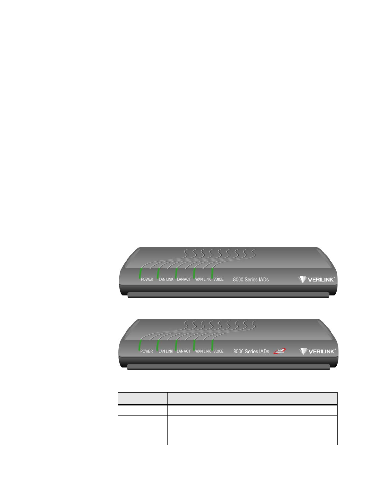
• Provides dyna mic and static IP routing and bridging capabil ities
• Provides fi rewall support via IP filtering
• Offers DHCP and NAT to support IP address management
• The “s” versions pr ovide support for MGCP and SIP with the flexibility to
support TDM/VoATM/VoIP applicat ions all in one unit
• Provides management capabilities including Telnet, SNMP, and TFTP
The Low P OTS Po rt IAD s are cha racterized b y their different WAN
interfaces:
• 8208 − provides voice servic es and WAN access via T1or E1.
• 8308/8304 − provides voice services and WAN access via SDSL.
• 8108/8104 − provides voice services and WAN access via ADSL.
• 8508/8504 − provid es voice services and WAN access via SH DSL.
Physical and electrical specifications for the 8208, 8308/8304, 8108/8104, and
8508/8504 IADs are listed in Appendix B, Specifications.
Low POTS Port Front Panel LED Status Indicators
The Low POTS Port front panels contain five LED status indicators. Each is
described in the table below.
Figure 1.1
Figure 1.2
LED Description
POWER Illu minates whe n th e IAD is p owered on .
LAN LINK Illuminates when there is an operational LAN connection on the
Low POTS Port Non-”s” Ve rsion Front Panel
Low POTS Port “s” Version Front Panel
Ethernet port.
LAN ACT Flashes when there is ac tivity on the Ethernet port.
Introduction 1-3
Page 30
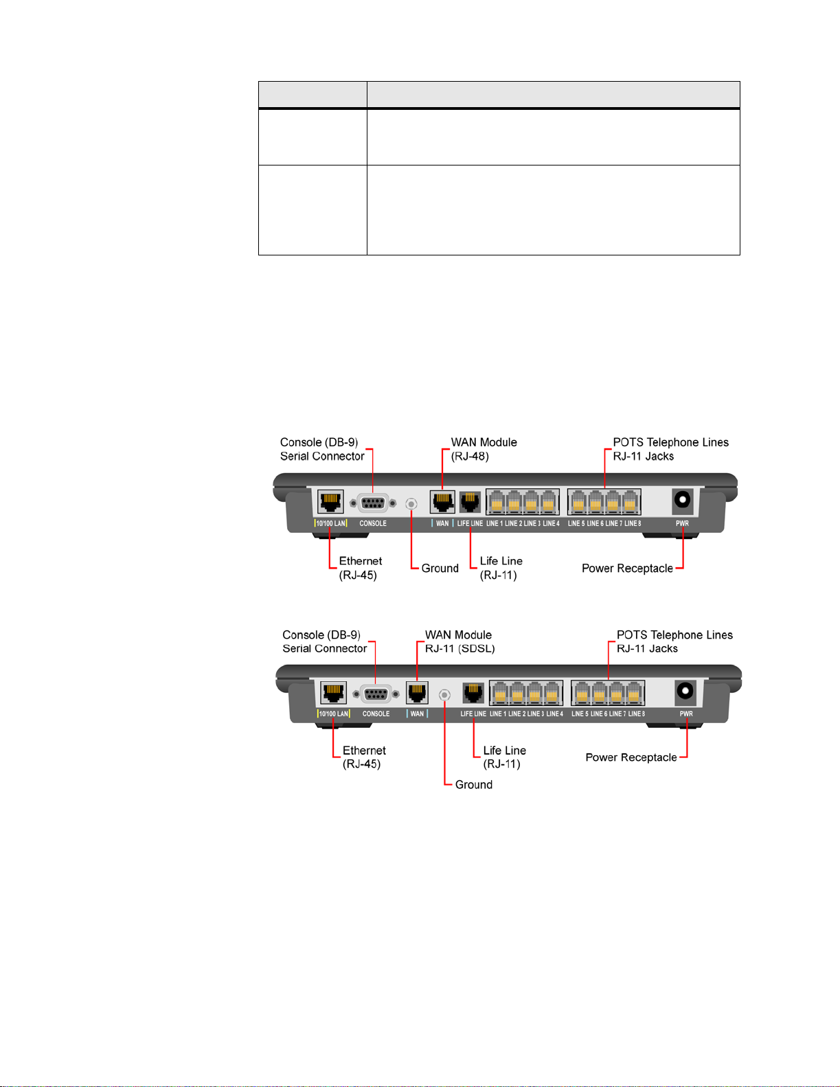
LED Description
WAN LINK Flashes as the IAD is establishing a link, and illuminates solid
when there is a proper connection on the WAN port and
synchronization has been achieved.
VOICE Illuminates when there is activity on the voice ports. When
connected to a CopperCom a nd Jetstream Voice Gateway, it
remains li t, an d blinks when th ere is ac ti vity. (This LED does n ot
remain lit when other type s of voice gateways are connected, but
will illuminate when a call is active.)
Low POTS Port Rear Panel Connectors
The Low POTS Port rear panels have the following connectors: 10/100 LAN,
CONSOLE, WA N, LIFE LINE, LINE 1-8 telephone connectors, and PWR . Each
of these connectors is described below. Each unit has a
which is illustrated in Figure 2.1.
Ground, the use of
Figure 1.3
Figure 1.4
T1/E1 Low POTS Port Rear Panel Connectors
SDSL Low POTS Port Rear Panel Connectors
1-4 8000 Series
Page 31

Figure 1.5
ADSL Low POTS Port Rear Panel Connectors
POWER (DC Power
Adapter)
Console (RS-232 Serial
Port)
10/100LAN
(10/100Base-T
Ethernet Port)
Figure 1.6
Connects the IAD to any AC 100-240 V outlet (adapter included).
Connects the IAD to a PC using a straight-through nine-pin serial (DB-9)
cable, for the purpose of using a terminal emulator for IAD configuration and
management.
Connects the IAD to the local area network using a CAT-5 straight-through
Ethernet c able, or directly t o a PC fo r acces sing via Telnet (us ing a
cross-over, customer-supplied cable).
SHDSL Low POTS Port Rear Panel Conne ctors
LINE 1-8 (Telephone
Interfaces)
LIFE LINE
WAN
Supports eight analog telephones via RJ-11 POTS ports.
Provides access to a telephone line when there is no power or voice gateway
to the IAD. Refer to Life Line Connection on page 2-12 for a description of
which unit uses which port for the Life Line connection.
NOTICE: The 8108 also uses the WAN connection for the Life Line connection.
Connects through WAN interface as follows:
• 8208 − T1/E1 (uses an RJ-48 connector)
• 8308/8304 − SDSL (uses an RJ-11 conne ctor)
• 8108/8104 − ADSL (uses an RJ-11 connector).
Introduction 1-5
Page 32

• 8508/8504 − SHDSL (uses an RJ-11 conne ctor).
Data Interfaces
The data connection through the IAD supports IEEE 802.1-compliant bridging
and routing. When the IAD is configured for routing, it supports Routing
Information Protocol (RIP) version 1, version 2, or static IP routing. The IAD
complies with RFC-1812 when interfacing with IPV4 routers. The IAD can
terminate the following data interfaces:
• ATM data transport via SDSL, SHDSL, and T1/E1 per RFC 1483 or RFC
2364
• Frame Relay data transport via SDSL and T1/E1 per RFC 1490
• Frame Relay data transport per RFC 1483 with Q.922 frames
Interfaces and Features of the High POTS Port Platform Architecture
High POTS Port Platform Architectu re
The High POTS Port IADs are based on a single-board, fixed-configuration
architecture. Each unit supports 1 WAN interface (T1/E1, SDSL, SHDSL), 1
LAN interface, and 12, 16, or 24 POTS interfaces via an RJ-21 connector.
These units are housed in a metal enclosure with an internal power supply.
All units are based on a common core design consisting of a Motorola Power
QUICC CPU, 16 Mbytes of dynamic memory, and 4 Mbytes of FLASH
memory. Voice packetization and processing are handled by Texas
Instruments Digital Signal Processors (DSP).
High POTS Port Features
The Verilink High POTS Port IADs provide a highly interoperable,
cost-effective voice and high-speed data integr ation solution that is compatible
with industry-leading DSLAM and Voice Gateway manufacturers. These
IADs prioritize voice packets and dynamically allocate bandwidth between
voice and data services. Features include the following:
• For SDSL, supports the following DSLAMs:
• ATM: Lucen t, N ort el, an d Nok i a
• Frame Relay: AccessLan, CopperMountain, and Paradyne.
• For SHDSL, supports the following DSLAMS for ATM: Lucent, No rtel, and
Nokia
• Supports the fol lowing Voice Gateways: CopperCom, JetStream, TdSoft,
Broadsoft, MetaSwitch, Cirpack, NuERA Tollbridge, Nortel , Gen era l
Bandwidth, Accelerated
• Provides seaml ess voice and high-speed data integration over SDSL, T1/E1,
or SHDSL
• Supports data from POTS and 10/100Base-T customer premise interfac es
1-6 8000 Series
Page 33

• Compatible with standards-based IP, ATM, and Frame Relay WAN
protocols
• Interwor king feature allows Frame Relay and ATM networks to exchange
data using either FRF.5 or FRF.8 proto col
• Provides RJ-21 POTS inte rface with Loop Start or Ground Start
• USI supports V.35 and EIA-530
• Provides dyna mic and static IP routing and bridging capabil ities
• Provides fi rewall support via IP filtering
• Offers DHCP and NAT to support IP address management
• Supports MGCP and SIP with the flexi bility to support TDM/VoATM/VoIP
applications all in one unit
• Provides management capabilities including Telnet, SNMP, and TFTP
The High POTS P orts are ch aracter ized by th eir differe nt WA N interfa ces:
• 8216s/8224s − provides voice services and high-spe ed Internet or corporate
connectivity over T1 or E1.
• 8316s/8324s − provides voice services and high-speed Internet or corporate
connectivity over SDSL.
• 8512s/8516s/8524s − provides voice services and high-speed Internet or
corporate connectivity over SHDSL.
High POTS Port Front Panel LED Status Indicators
The High POTS Port front panels contain seven LED status indicators. Each
is described in the table below.
Figure 1.7
LED Description
POWER Illu minates whe n th e IAD is p owered on .
LAN LINK Illuminates when there is an operational LAN connection on the
LAN Activity Flashes when there is acti vity on the Ethernet port.
WAN Link Flashes as the IAD is establishing a link, and illuminates solid
VOICE Illuminates when there is activity on the voice ports. Remains lit
High POTS Port Front Panel
Ethernet port.
when there is a proper connection on the WAN port and
synchronization has been achieved.
when connected to a Jetstream Voice Gateway, and blinks when
there is activity.
Introduction 1-7
Page 34

LED Description
DCE LINK Illuminates when there is a link between the IAD and data
communic ations equipment (D CE).
DCE ACT Illuminates or blinks when there is activity on the DCE link.
High POTS Port Rear Panel Connectors
The High POTS Port rear panels have the following connectors: 10/100 LAN,
CONSOLE
BATTERY BACKUP
INPUT.
typical
, T1 (or DSL, depending on model), DCE V.35/RS-530 (USI),
, Voice Lines, LIFE LINE, O n/Off Switch, a nd AC POWE R
Each of these is described below. Each unit also has a Ground, a
diagram of which is shown in Figure 2.1.
Figure 1.8
Figure 1.9
T1/E1 High POTS Port Rear Pane l Connectors
SDSL and SHDSL High POTS Port Rear Panel Connectors
10/100 LAN
(10/100Base-T
Ethernet Port)
1-8 8000 Series
Connects the IAD to the local area network using a CAT-5 straight-through
Ethernet c able, or directly t o a PC fo r acces sing via Telnet (us ing a
cross-over, customer-supplied cable). The data interfaces connect through the
IAD supporting IEEE 802.1-compliant bridging and routing. When configured
for routing, supports Routing Information Protocol (RIP) version 1, version 2,
or static IP routing. The IAD complies with RFC-1812 when interfacing with
IPV4 routers . The IAD can terminate the following data inte rfaces:
• ATM data transport via SHDSL, SDSL, and T1/E1 per RFC 1483 or RFC
2364
• Frame Relay data transport via SDSL and T1/E1 per RFC 1490
Page 35

• Frame Relay data transport per RFC 1483 with Q.922 frames
Console (RS-232 Serial
Port)
WAN (T1 or DSL,
Depending on IAD
Model Number)
DCE V.35/RS-530
(USI)
Battery Backup
Voice Lines
LIFE LINE
Connects the IAD to a PC using a straight-through nine-pin serial (DB-9)
cable, for the purpose of using a terminal emulator for IAD configuration and
management.
Connects through WAN interface as follows:
• 8216s/8224s − T1/E1 (uses an RJ-48 connector)
• 8316s/8324 − SDSL (uses an RJ-11 connector)
• 8512s/8616s/8524s − SHDSL (uses an RJ-11 connector).
When configured as an RS-530 port with a straight-through DB-25 serial
cable, connects to your leased-line DSU/CSU equipment. When configured
for use as V.35, Black Box Corporation provides a cable (FA058) for
conversion. To convert from RS-530 to RS-449, Black Box provides a cable
EDN57J. Contact Black Box for availability of and support for these cables.
Connects a battery backup accessory (future feature).
Supports 12, 16, or 24 analog telephones via RJ-21 connectors.
Provides access to a telephone line when there is no power or voice gateway
to the IAD. Refer to Life Line Connection on page 2-12 for a description of
which unit uses which port for the Life Line connection.
AC Power Input
Data Interfaces
Connects the IAD to any AC 100-240 V outlet.
The data connection through the IAD supports IEEE 802.1-compliant bridging
and routing. When the IAD is configured for routing, it supports RIP version
1, version 2, or static IP routing. The IAD complies with RFC-1812 when
interfacing with IPV4 routers. The IAD can terminate the following data
interfaces:
• ATM data transport via SDSL, SHDSL, and T1/E1 per RFC 1483 or RFC
2364
• Frame Relay data transport via SDSL and T1/E1 per RFC 1490
• Frame Relay data tra nsport per RFC 1483 with Q.922 frames
Introduction 1-9
Page 36

1-10 8000 Series
Page 37

C HAPTER
2
C
HAPTER
2
Q
UICK
This chapter describes the steps to install, connect, and set the IP address of
the 8000 Series IAD. It introduces the menu interface and describes how to
perform basic configuration for common LAN and WAN environments. It
also describes basic operations such as resetting the IAD and logging off.
In many cases, all the information you ne ed to get an IAD up and running is
included in this single chapter. In most installations, you will proceed through
these topics in order. If your situation varies, you will find more detailed
information on installation, connection, configuration, and troubleshooting in
the chapters that follow this Quick Start Guide.
S
TART
G
UIDE
Unpacking the IAD
Each IAD is packed and shipped in a durable container. Unpack and carefully
remove th e IAD f rom the package an d packi ng mate rial.
IAD Packag e
Components
Each IAD is shipped with the components listed below. As you unpack them,
note their condition and identity and compare the list with the packing list in
the package.
• AC power adapter and cord (6 feet long), or AC power cord
• Agency Comp liance informati on sh eet
• Ethernet cable (straight through), 7 feet long
• WAN cable, 7 feet long
If you note any visible damage or missing components, notify the shipping
company immediately to make a damage claim. Contact the company from
which the IAD was purchased (Verilink, or an authorized distributor) to
obtain a Return Material Authorization (RMA) for return of damaged
equipment or to order missing components. (Refer to Support from Verilink
on page xxvii.)
NOTICE: Verilink suggests you keep the shipping container and packing material
for future storage or shipping of the unit.
Quick Start Guide 2-1
Page 38

Installing the IAD
After you unpack the IAD, find a suitable location to install the unit. Ideal
locations include a computer equipment room or a telephone or wiring closet.
You can locate the IAD on a table or shelf, or it may be wall-mounted. Install
the IAD in a location that is generally protected and where it will be
undisturbed.
AC Power and Uninterruptible Power Supply
The IAD requires access to AC power (NEMA 15-3R). Make sure the IAD is
located within 6 ft of an AC power outlet. Locate the nearest power outlet and
plug in the supplied AC power adapter or AC power cord. If there is an
uninterruptible power supply on premises, plug the AC power adapter or cord
into that p ower so urce.
Ensure the power cord conveniently and safely reaches the rear panel of the
IAD whe re the po wer plug or adapt er jack is located.
NOTICE: Do not attach the AC power adapter or power up the unit at this time.
Clearance Requirements
When you install the IAD horizontally, make sure you maintain at least 2
inches of horizontal distance from other IADs or other electronic equipment
to ensure adequate ventilation and heat dissipation.
NOTICE: Due to generated heat, 8000 Series IADs should not be stacked on top
of each other.
Wiring Requirements
Make sure the telephone wiring, LAN, and WAN cables reach the IAD and
can be dressed in a manner that is safe for the wiring, does not pull or create
lateral stress on the connectors or ports on the rear of the IAD, and does not
present a trip hazard to personnel working in the vicinity of the equipment.
Do not connect any cables or wiring at this time.
Connecting the IAD Via a Terminal Emulator
The IAD is configured and managed from either the console or Ethernet port.
A Telnet session is usually used to access the IAD via Ethernet. After you use
a terminal emulator program via the console port (refer to Console Port Pin
Assignments (DB-9) on page B-6 for console port specifications) to set the IP
address, you may continue to use a terminal emulator via the console port.
The factory-set default IP address is
192.168.1.254 for the Ethernet port.
2-2 8000 Series
Page 39

NOTICE: After a period of inactivity (3 min by default), the IAD automatically
terminates console-based and Telnet sessions to maintain security. To
change this value, see Configure Console Timeout on page 3-15.
Before you can connect to the IAD via Telnet, make sure the IP address is set
correctly for this network by following these steps:
• Connect the IAD to a PC
• Log in to the IAD
• Set th e IP add re ss
Each of these steps is described in detail below.
NOTICE: Ensure the IAD and PC are both powered OFF before connecting the
console cable. If both devices are not turned off when you connect the
cables, you may plac e the IAD in an unstable state, and you may need
to reset one or both devices before you can perform configuration tasks.
Connecting the IAD to a PC
To connect the IAD to a PC via the console port, follow the steps below.
1 Turn off both devices and insert the male connector of a DB9 serial cable
into the console port on the IAD.
2 Insert the female connector of the cable into a serial (COM) port on your
PC.
WARNING: For Ground Start applications, ensure the IAD is properly grounded. Refer to
Figure 2.1.
Quick Start Guide 2-3
Page 40

Figure 2.1
Typical Grounding Diagram
3 With the console cable connected, plug the AC power adapter into the IAD.
This starts the IAD, and it executes the boot process to begin normal
operation. Verify that the Power indicator on the front pa nel illuminates.
NOTICE: For “cold start” access, the IAD default (factory-set) IP addre ss is
192.168.1.254 on the Ethernet side.
NOTICE: For “Ground Start” applications, all elements in the voice path must be
set to “Ground Start.”
NOTICE: As the IAD boots, it sends status messages to the console port. If you
are connected, you will see the boot sequence progress.
NOTICE: This unit should be installed by qualified service personnel only, and
must be connected to a socket outlet with protective earthing
connection.
Logging in via a Terminal Emulation Program
2-4 8000 Series
With a serial cable connected, follow the steps below to log in to the IAD:
1 Open a terminal emulatio n program (Hyperterminal, for example).
Page 41

2 Select the COM port to which the IAD is connected.
3 Type or select the settings described in the table below and save your
changes.
Setting Value Setting Value
Bits per second 19,200
Data bits 8
Parity None
Stop bits 1
Flow control None
Emulation ANSI or VT100
4 Press Enter. The IAD displays the login message:
Enter Login ID >
NOTICE: If the IAD does not respond, make sure the IAD is powered up, check
the cable and connections, and review the settings.
5 Type the default superv isor level user ID (Supervisor) (or your user ID,
if changed) and press Enter. Note that both the user ID and password are
case-sensitive. The table below lists the default user IDs and passwords.
NOTICE: Refer to Chapter 3, “Administration”, for detailed procedures regarding
all IAD administrative tasks. Follow these procedures after performing
the basic set-up functions described in this “Quick-Start Guide”.
Security Level User ID Password
User <Enter> <Enter>
Network Administrator NetMan <Enter>
Supervisor Supervisor supervisor
6 The IAD displays the password message:
Enter Password >
7 Type the default password (supervisor, or your password if different)
and press Enter. If login is not successful, the IAD displays the following
message:
Invalid UserID or Password - Try again
Press any key to continue...
8 Press any key, and repeat the login sequence. If you cannot log in, call you r
support provider for assistance.
When you first log in, the IAD displays the Main menu (Figure 2.2). The
menu may vary, depending on the IAD.
Quick Start Guide 2-5
Page 42

NOTICE: If you are entering the menu to change a previously established
configuration, refer to Managing Configuration Files on page 4-1 to
save the current configuration for fast restoration in case the new
configuration does not work.
Figure 2.2
Main Menu
NOTICE: Options vary depending on the voice gateway selected in the Voice Path
Configure command. Refer to Voice Path Configuration on page 4-60.
NOTICE: When the IAD prompts you for input, the current value is displayed in
parentheses. To conveniently accept the current value, just press Enter.
Setting the Ethernet Port IP Address
Before you configure the Ethernet IP address, you should know the IP address
and subnet mask that are to be assigned to this port. They may be displayed
on the work order, or you may obta in or determine the appropriate IP address
by consulting with the network administrator.
The IAD is shipped with the IP address set to
subn et ma sk set to 255.255.255.0. To configure a port IP address, follow
the steps below.
1 On the Main menu, type “2.” The IAD displays the Router Configuration
menu (Figure 2.3).
2-6 8000 Series
192.168.1.254 and the
Page 43

Figure 2.3
Router Configuration Menu
2 Type “C” to select Configure Port IP. The IAD displays the available
interfaces. The available interfaces that display depend on the specific IAD
as shown in Figure 2.4 and Figure 2.5 belo w.
Figure 2.4
Figure 2.5
8308 Available I nterfaces
8208 Available I nterfaces
Quick Start Guide 2-7
Page 44

3 Type “2” to set the IP address for the Ethernet port. If the IP address is
configured for the port, the IAD displays information about the interface
and a prompt such as that shown in the example below:
4 Type the ID number of the connection you want to configure (in this case,
“0”) and press Enter.
5 Type the new IP address, and press Enter (or press Enter to retain the
current IP address). The IAD displays the Current Subnet Mask and
prompts you for a new one.
6 Type the new Subnet Mas k (usuall y 255.255.255.0) and pres s Enter. The
IAD prompts you to select High or Normal priority.
7 To give the interface normal priority, type “N” or press Enter.
8 Type “Y” or Enter to save the new IP address and subnet mask.
9 To exit, press Escape, and then type “Y” to ter mina te the sessi on.
10 Quit the terminal emulator program.
11 Reset the IAD as described below (“Resetting the IAD”) for the new IP
address to be in effect.
NOTICE: When you configure the IAD, you must restart the IAD each time you
change the settings for those changes to take effect. You may make
several configuration changes before resetting.
If you plan to use Telnet for configuration tasks (Connecting via Telnet on
page 2-9), this is a good time to disconnect the serial cable from the PC and
IAD.
Setting the WAN Port IP Address
To set the WAN port IP address, follow the same procedures as those listed in
Setting the Ethernet Port IP Address on page 2-6.
Resetting the IAD
Many configuration tasks require that you reset (or restart) the IAD before the
new settings or configuration will take effect. When you use the menu
interface (or the Command Line Interface - Chapter 6, “Command Line
Interface”) to make changes , or chang e the phys ica l character istics of the IAD
(such as the Ethernet port MAC address), you must reset the IAD.
2-8 8000 Series
Page 45

The IAD stores all configuration settings in memory. When it restarts, it loads
the last configuration saved before it was powered down or restarted. When
restarting is required, it will be included as a step in the configuration process.
You can reset the IAD in one of the two following ways:
To reset the IAD from the menu:
1 On the Main menu, type “R” to select Reset System.
2 Type “R” again at the prompt. This resets and starts the IAD with your
new settings.
3 To log in again, enter your user ID and password.
To reset the IAD manually, unplug the power adapter from the IAD and then
plug it back in.
CAUTION: Be sure to complete your task and return to the Main menu before
Connecting via Telnet
restarting the IAD manually. Resetting the IAD terminates all
telephone calls and computer sessions in progress. You should ensure
there are no services being rendered before resetting the IAD.
To manage the IAD via the LAN (or Intranet), you must set an IP address for
the Ethern et port be fore you can use Telnet t o access t he IAD .
Although you can also access the IAD using Telnet via the WAN (provided a
management DLCI or PVC is configured along with a WAN IP address), this
section describes connecting via the LAN. For information about setting the
IP address of the WAN port (Refer to Managing Configuration Files on
page 4-1.)
If you configure a RADIUS Client, you must use a RADIUS-authenticated
User ID/password for Telnet access. If the RADIUS server or the connection
to the RADIUS Client goes down, Telnet access will not be permitted. For
information about configuring a RADIUS client (Refer to RADIUS Server
Settings on page 3-4.)
Running Telnet
Before you use Telnet to log into the IAD, ensure the IAD and your PC are
connected to the same network via straight-through Ethernet cables (or
directly connected via a cross-over cable), and you know the IP address of the
IAD. Both devices must be on the same subnet.
To log in, follow the steps below.
1 Run Telnet on your PC.
2 Type the IP address of the Ethernet port (refer to Setting the Ethernet Port
IP Address on page 2-6), click Connect and then press Enter to gain the
attention of the IAD. The IAD responds by prompting you to enter your
Login ID.
Quick Start Guide 2-9
Page 46

3 Type your user ID and press Enter. The IAD will then prompt you to enter
your Password.
NOTICE: After a period of inactivity (thre e minutes by default), the IAD
automatically terminates console-based and Telnet sessions to maintain
security. To change this value, refer to Configure Console Timeout on
page 3-15.
NOTICE: Default user IDs and passwords are listed in the table on page 2-5. For
information on security levels, and user ID and password management
see IAD Security on page 3-1.
4 Type your password and press Enter to di splay the Main menu (Figure 2.2).
NOTICE: The user ID and password transmit as clear text, which may be
captured by unauthorized individuals. If you are concerned with
network security, you may not want to use Telnet to configure the IAD.
Navigating the IA D
Menu Interface
Entering Settings and
Values
Using Default or
Current Values
Menus in the IAD configur ation sys tem are ar ranged hierarch ically. Th at is,
you select single-key options to navigate down to display specialized menus
and specific tasks, and press the Escape key successively to return back to
menus higher in the interface.
The specific menus, submenus, and commands that display depend on the
interfaces for the specific IAD, the options configured, and the security level
you use to log in.
To select a menu item, type the option displayed to the left of the item.
Although character options are displayed in upper case, the IAD accepts both
upper- and lower-case options. It is not necessary to press Enter after typing
the selection − the IAD immediately responds with a request for input or
another menu for more options.
For a hierarchical map of the Main menu, its menus and commands, see
Appendix A.
When the IAD requests input for a setting or configuration value, type it at
the prompt. Press the Enter key to terminate the input and proceed to the next
step. The IAD responds with error messages if a value is incorrect, or it
displays the current menu so you can continue with related tasks.
The IAD displays a default or current value in parentheses immediately to the
right of ea ch mess age, just t o the le ft of the command prompt . To acc ept this
value, press the Enter key.
2-10 8000 Series
For example, whe n the prompt asking you to enter a new Subnet mask
displays, you may press Enter to cause the IAD to set
255.255.255.0 as the
Subnet Mask value. Using the Enter key to skip through default or current
values often speeds the process of proceeding through a family of input steps
to more quickly reach the input step where you wish to change a value.
Page 47

Exiting the Menu
Interface
To exit the menu interface, return to the Main menu using the Escape key,
and press Escape one more time. When the IAD asks you to confirm, press
“Y” to exit or press Return to accept the default value “N” to cancel the exit.
NOTICE: After exiting, you can quit the terminal emulator or Telnet session. If
Basic IAD Configuration
Each IAD is shipped with a default configuration set in the file default.st.
Once you make any changes to your IAD, a new file is created to store the
new configuration—config.st—to preserve the your settings.
After you have configured the IAD for correct operation in a customer’s
premises, the current system settings in the config.st file may be saved as the
custom default configuration file (custdef.st), and you may choose to set the
IAD to boot from this file each time it is reset. You may also copy this file to
a PC or TFTP server for downloading to other identically configured IADs.
Once you have replaced the original custdef.st file, you cannot retrieve it.
Consider copying the custdef.st file to a safe location before replacing it.
To perform basic IAD configuration, follow the steps below.
you made changes to the configuration that require resetting the IAD,
be sure to do so before exiting.
• Configure the LAN IP address, if not already completed (page 2-6).
• Configure each of the WAN options and the DSLAM profile (page 4-2 and
the pages following 4-1).
• Create and confi gure at least one DLCI (page 4-31) or PVC (page 4-24) for
data traffic and set the WAN IP add re ss (p age 2-6).
• Configure static or default route (page 4-42) or enable bridging (page 4-53)
for all data traffic.
• Create and configure a DCLI (page 4-31) or PVC (page 4-24) for voice
where required, and select appropriate voice gateway settin gs (page 4-61).
• Reset the IAD (page 2-8) to enable all configuration changes.
NOTICE: You must reset the IAD after configuring IP addresses before you may
add routes.
Connecting LAN, WAN, and Telephones
This section details how to connect the IAD to the computer and telephone
systems the IAD is intended to support.
Before proceeding, make sure you have an appropriate serial cable for your
PC, identify the LAN switching equipment where you’ll connect the IAD,
identify the telephone cables, and verify that WAN service is installed and
configured by the service provider.
When you’ve completed this section, reset the IAD so it can synchronize
these physical connections.
Quick Start Guide 2-11
Page 48

Ethernet LAN Connection
The Ethernet LAN port on the rear of the IAD is an RJ-45 jack for
10/100Base-T Ethernet cables. If the IAD is intended to act as an Internet
gateway for the LAN in the customer’s premises, connect the IAD to the
switch, hub, or router using an Ethernet straight-through cable.
NOTICE: You may temporarily connect the IAD directly to a PC for Telnet
configuration (without going through a hub or router). The Ethernet
receiver automatically detects the type of Ethernet cable
(customer-supplied).
WAN Connections
WAN connections vary, based on the WAN interface on your IAD. The 8308
is an SDSL-equipped IAD and uses an RJ-11 connector to connect to the rear
panel WAN connection. To make the connection, plug the SDSL cable into
the RJ-11 WAN connector. (Refer to page B-6.) The 8208 is a
T1/E1-equipped IAD and uses an RJ-48 connector on the IAD rear panel for
WAN connection. To make the connection, plug the cable from the ATM
network into the RJ-45 WAN connector. Refer to page B-6 to see the pinouts
for the T1/E1 connection.
Telephone Connections
The 8000 Series IADs provide eight RJ-11 ports for POTS devices. These
devices may be POTS telephones, modems, FAX machines, or other
POTS-compatible devices.
Life Line Connection
The IADs have an RJ-11 Life Line associated with the POTS line. (Refer to
the table b elow.) T he Life L ine is a n analog l ine that can be directly
connected to the PSTN. In case of power loss or loss of voice gateway
connection, the designated POTS line automatically switches to the Life Line
connection.
Product Life Line Port
8208/8208s, 8308/ 8308s/8304/8304s,
8216s/8224s/8316s/8324s/8512s/8516s/8524s
8104/8104s, 8504/ 8504s POTS Line 4
8108/8108s, 8508/ 8508s POTS Line 8
NOTICE: The 8104/8108 uses the WAN connection for the Life Line connection.
POTS Lin e 1
2-12 8000 Series
Page 49

USI Connection
If your IAD is equipped with a USI port, you may connect it now. Located on
the rear panel, the port uses a shielded, DB25 connector. The connector is
DCE − data is transmitted on the receive pin and received on the transmit pin.
The V.35 and EIA-530 interfaces use different voltage levels. You must
supply the appropriate cable for each interface. Refer to Appendix B for
pinout connections.
Confirming Proper Setup
When you have completed the tasks in this chapter, reset the IAD and test
your configuration for proper data and voice operation. Reset the IAD
(page 2-8) to synchronize the physical connections using the verification
procedure described in Chapter 8.
Quick Start Guide 2-13
Page 50

2-14 8000 Series
Page 51

C HAPTER
3
C
HAPTER
3
A
DMINISTRATION
This chapter describes how to control security to your IAD, validate users
using a RADIUS Server, configure SNMP via IP or AAL2 Em bedded
Operations Channel (EOC), upgrade IAD software, and perform other general
and utility-oriented tasks.
NOTICE: When the IAD prompts you for input, the current value is displayed in
parentheses. To conveniently accept the current value, just press Enter.
IAD Security
NOTICE: After setting IAD Security pa rameters, you m ust reset the IAD
(page 2-8) for the new settings to take effect.
To maintain IAD security, the IAD provides multi-level login access using a
single user ID and password, which you can set at the following levels:
• User
• Network Administr ator
• Supervisor
The user ID at the User secu rity level ma y be modified , but the user ID at the
Network Administrator and Supervisor levels may not.
The password for each security level may be changed. Although you may use
the same password for all security levels, Verilink recommends that you use a
different one for each level. The table below lists the privileges available at
each secur ity level.
Administration 3-1
Page 52

Security level Privileges
Supervisor This user level is the highest level. Users who log in as
Supervisor have full access to all IAD features (menu
and command line interface , including changing User
security level, user ID, and any level passwords, plus
complete IAD configuration capability.
Network Administrator At this level, users may perform tas ks that alter the
network settings of the IAD, pl us are abl e to acces s to all
data networking conf iguration menus, and can update
routing and bridging information and statu s.
This user can change the password at this leve l, and also
can change the User-level User ID and password, and
can access all display-only menus.
At this level, user s cannot modify WAN or LAN
settings, alt er derived timing, use the Com m and Line
Interface, or modify voicepath settings.
User At this level, the user has access to display-only menus ,
and can view the current configuration, interfa ce, and
media statistics, routing and bridging information, and
status. The user may ch ange this level User ID and
password, but cannot make or save any changes to the
configuration of the IAD.
To maintain IAD security, a user with Supervisor privileges should modify
the User security level user ID and passwords for both User level and
Network Administrator level prior to placing the IAD into production.
The table below lists the default values for the user IDs and passwords:
Security Level User ID Password
User <Enter> <Enter>
Network
Administrator
Supervisor Supervisor supervisor
The user ID and password may contain up to 17 alphanumeric characters.
These values are case sensitive; spaces and punctuation characters are not
allowed.
The IAD can store only one user ID and password at each security level.
Password Configuration Menu
To access the Password Configuration menu, type “8” (Configure Login) on
the Main menu.
NetMan <Enter>
3-2 8000 Series
Page 53

Figure 3.1
Password Configuration Menu
Change User ID
To change the user ID for the User security level (the only security level that
allows the user ID to be changed), follow the steps below.
1 Type “1” to change t he user ID for the User security level.
2 Type the new User ID (up to 17 characters) and press Enter. The IAD
informs you that the user ID has been updated.
3 Reset the IAD.
Including User IDs and Passwords in Config Files for Multiple Site
Distribution
If you create master configuration files for distribution to multiple IADs, you
may include the user ID and passwords directly in the config.st configuration
file to reduce configuration tasks.
NOTICE: When the user ID and passwords are stored in the config.st file, the IAD
automatically rewrites the configuration file during the next system
boot. The user ID and passwords are stripped from the configuration
file before saving to prevent a security risk.
Using a text editor, update the config.st file by adding the following user
category and attributes:
[user]
userid={string}
password={string}
netman-password={string}
support-password={string}
The password parameter is for User-level access, the “netman” password is
for Network-Administrator-level access, and the “supervisor” password is for
Superviso r-level access.
Administration 3-3
Page 54

Change User Password
To change a password at any security level, you must sign on at or above the
security level you’re changing and follow the steps below.
1 Type “2”, “3”, or “4” on the Password Configura tion men u to change t he
password for the selected level.
2 Enter the password for the current level.
3 Enter the new password after the prompt, or press Enter to enter a null
password.
4 Enter the new password (or Enter) again, to confirm the change.
The IAD immediately updates the password. The next time you log in at that
level, the new password will be in effect.
NOTICE: You cannot use the Escape key to exit the password update command.
To exit, deliberately enter an incorrect password at the confirmation
step, or reset the IAD.
RADIUS Server Settings
You can use a RADIUS Server to determine the validity of unknown user
ID/password pairs in your IAD. Verilink does not provide a RADIUS Server;
the user must provide a RADIUS Server to use this feature. For more
information on RADIUS Server, see RFC 2865.
If you co nfigure a RADIU S Server, the IAD must b e able to succes sfully
connect to the RADIUS Server. This requires WAN configuration, IP
configuration, static or default routes, and other configurations for your
network. Additionally, you must use a RADIUS-authenticated user
ID/password for Telnet access. If the RADIUS Server becomes inoperative,
Telnet access will not work.
To use a RADIUS Server, set the following options:
• Change the primary or secondar y RADIUS Server Address
• Change the primary or secondar y RADIUS Server Encryption Secret
• Display RADIUS Server Configuration
Each of these settings is described below.
Change Primary (or Secondary) RADIUS Server Address
To change the primary or secondary RADIUS Server address, follow the steps
below.
1 Type “5” on the Password Configuration menu to se lect Change Primary
RADIUS Server Address or Type “7” to select Change Secondary
RADIUS Server Address. The IAD displays the current Radius Server and
prompts you to enter a new one by IP Address or name.
3-4 8000 Series
2 Type the IP address in one of the following formats and press Enter.
Page 55

IP address
Fully-qualified host and domain names
(for example: radius.Verilink.com—maximum 42 bytes)
NOTICE: If you enter host and domain names, you must configure the IAD as a
DNS client (see page 4-46).
3 Reset the IAD.
Change Primary (or Secondary) RADIUS Encryption Secret
To change the primary or secondary RADIUS encryption key, follow the
steps below.
1 Type “6” on the Password Configuration menu to se lect Change Primary
RADIUS Encryption Secret or type “8” to change Secondary RADIUS
Encryption Secret. The IAD displays the current Radius Encryption Secret
and prompts you to enter a new one.
2 Type the new encryption key and press Enter.
3 Reset the IAD.
Display RADIUS Configuration
To display the current RADIUS Server configuration, follow the steps below.
1 Type “9” on the Password Configuration menu to select Display RADIUS
Configuration. The IAD displays the following information :
Primary RADIUS Server:
Primary RADIUS Secret:
Secondary RADIUS Server:
Secondary RADIUS Secret:
Disable RADIUS Configuration
To disable the RADIUS Server configur ation, type “X” on the Password
Configuration Menu (Figure 3.1) . The IAD disables both the Primary and
Secondary RADIUS Server configur ations.
Setting Up SNMP
NOTICE: After updating SNMP settings, you must reset the IAD (refer to
SNMP is supported via Internet Protocol (IP) and the Loop Emulation System
Embedded Operation Channel (LESEOC). The LESEOC interface is only
available with either the AAL2/LES CAS or ELCP voice gateway. This
interface allows the voice gateway to monitor and control specific IAD
operational parameters.
page 2-8) for the new settings to take effect.
Administration 3-5
Page 56

NOTICE: Some voice gateways with this feature require a read-write community
name of LESEOC to be configure d in the IAD.
The SNMP Configuration menu is accessible from the Main menu. You may
enable SNMP via IP, EOC, or both. Traps may be sent to a configurable IP
address, the EOC, or both. The System Contact, System Name, and System
Location may also be con figured. T hese valu es are acc essible via the R FC
1213 MIB.The IAD supports the following SNMP settings:
• System Contact
• System Name
• System Location
• SNMP Community
• SNMP Trap Host IP Address
The following SNMP traps are supported:
• System reset
• Attempts to acce ss SNMP with an invalid community name
• Starting and stopping TFTP within SNMP
The IAD supports MIBs for RFCs 1213, 1317, 1406, 1493, and 1463 as well
as af-vmoa-0174 (AAL2/LES MIB).
SNMP Configuration Menu
To display the SNMP Configuration menu, type “7” on the Main menu. Each
of the menu’s configuration options is described below.
Figure 3.2
SNMP Configuration Menu
3-6 8000 Series
NOTICE: The strings you ent er in SNMP are not case se nsitive.
Page 57

Enable/Disable SNMP via IP
To Enable or Disable SNMP via IP, follow the steps below.
1 Type “E” on the SNMP Configur ation menu t o ena ble or di sable SNMP via
IP. The IAD displays the current status of SNMP.
2 To enable SNMP, type “E” or “D” to disa ble. The IAD saves the
configuration (if changed).
3 Continue with other SNMP settings, or press Escape to return to the Main
menu.
4 Reset the IAD.
Enable/Disable SNMP via EOC
To Enable or Disable SNMP via EOC, follow the steps below.
1 Type “F” on the SNMP Configur ation menu t o ena ble or di sable SNMP via
EOC. The IAD d isp lay s the current status of SNM P .
2 To enable SNMP, type “E” or type “D” to disable. The IAD saves the
configuration (if changed).
3 Continue with other SNMP settings, or press Escape to return to the Main
menu.
4 Reset the IAD.
Enable SNMP via Both IP and EOC
To Enable SNMP via Both IP and EOC, follow the steps below.
1 Type “A” on the SNMP Configuration menu to enable SNMP via IP and
EOC. The IAD saves the configur ation.
2 Continue with other SNMP settings, or press Escape to return to the Main
menu.
3 Reset the IAD.
Disable SNMP via Both IP and EOC
To Disable SNMP via both IP and EOC, follow the steps below.
1 Type “B” on the SNMP configuration menu to disable SNMP via IP and
EOC. The IAD saves the configur ation.
2 Continue with other SNMP settings, or press Escape to return to the Main
menu.
3 Reset the IAD.
Configure System Contact
To config ure the Sy stem C ontact, fol low th e steps bel ow.
Administration 3-7
Page 58

1 Type “P” on the SNMP Configuration menu to configur e system contact
(up to 39 alphanumeric characters). The IAD displays the current system
contact and prompts you to enter a new one.
2 Type the name of the new contact person or department and press Enter.
The IAD save the configuration.
3 Continue with other SNMP settings, or press Escape to return to the Main
menu.
4 Reset the IAD.
Configure System Name
To config ure the Sy stem N ame, foll ow the s teps belo w.
1 Type “N” on the SNMP Configuration menu to configure the system name
(up to 39 alphanumeric characters). The IAD displays the current system
name and prompts you to enter a new one.
2 Type the new system name and press Enter. The IAD saves the
configuration.
3 Continue with other SNMP settings, or press Escape to return to the Main
menu.
4 Reset the IAD.
Configure System Location
To configure the System Location, follow the steps below.
1 Type “L” on the SNMP Configuration menu to configur e the system
location (up to 39 alphanumeric characters). The IAD displays the current
system location and prompts you to enter a new one.
2 Type the name of the new server location and press Enter. The IAD saves
the configuration.
3 Continue with other SNMP settings, or press Escape to return to the Main
menu.
4 Reset the IAD.
Configure SNMP Community
The value you set must match the write community name of the SNMP host
to enable the SNMP Set operation. If you enable SNMP and the read-write
Community Name is null, SNMP enters read-only mode with a community
name of “public.”
1 Type “L” on the SNMP Configuration menu to select Configure System
Location. The IAD displays the current community name and prompts you
to enter a new one.
3-8 8000 Series
2 Type the name of the SNMP community to which your system belongs and
press Enter. The IAD saves the configura tion.
Page 59

3 Continue with other SNMP settings, or press Escape to return to the Main
menu.
4 Reset the IAD.
Configure SNMP Trap Host IP Address
To configure the SNMP Trap Host IP Address, follow the steps below.
1 Type “T” on the SNMP Configuration menu to select Selec t Configure
SNMP Trap Host IP Address of the system setup for trap operations. The
IAD displays the current IP addre ss and prompts you to enter a new one.
2 Type the IP address and press Enter. The IAD saves the configuration.
3 Continue with other SNMP settings, or press Escape to return to the Main
menu.
4 Reset the IAD.
Enable/Disable SNMP Traps via EOC
To Enable or Disable SNMP Traps via EOC, follow the steps below.
1 Type “U” on the SNMP Configuration menu to enable or disabl e SNMP
traps via EOC. The IAD displays the current status.
2 To enable traps via EOC, type E. To disable them, type D. The IAD saves
the configuration.
3 Continue with other SNMP settings, or press Escape to return to the Main
menu.
4 Reset the IAD.
Configure Restart Trap Maximum Delay
To configure Restart Trap Maximum Delay, follow the steps below.
1 Type “D” on the SNMP Configuration menu to configur e the restart trap
maximum delay time. The IAD prompts you to input a new value.
2 Type the new value in seconds and press Enter. The IAD saves the
configuration.
3 Continue with other SNMP settings, or press Escape to return to the Main
menu.
4 Reset the IAD.
Defining Different SNMP Version 3 Categories
SNMP 3.0 requires the configuration of six data structures on the SNMP 3.0
menu (Figure 3.3), which is accessible from the SNMP Configuration menu.
Menu options are available to configure a default set of structures, which will
allow SNMP 1.0 or SNMP 3.0. Choose Option 3 on the SNMP 3.0
Configuration menu to set a simple default configuration.
Administration 3-9
Page 60

Figure 3.3
SNMP V3 Configurat ion Me nu
Two SNMP “community entries” are generated: public (read-only
community), and a read-write community. Since a read-only community of
public is the default for all SNMP implementations, you are encouraged to
reconfigure the first community entry to a more secure value.
The “targ et entries” specify who may access the IAD via SNM P. The first
entry, named “everyone,” allows access from the entire Internet. Entries are
added if an IP trap host is configured, or if EOC access is configured. For
example, if you want only IP addresses 1.2.3.0 through 1.2.3.255 to have
SNMP access to the IAD, you will reconfigure the target entry with the
address of 1.2.3.0, and the mask 255.255.255.0. Note EOC access is specified
by the reserved IP address 255.255.255.255.
The “group entries” specify which version of SNMP to allow: 1.0 or 3.0 (user
security m odel).
The “acc ess entry” specifi es which v ersion of SNMP to allow, the sec urity
level (MD5 authorization encryption), and which views are accessible.
The “view entry” specifies which portion of the MIB is accessible or not
accessible. For exa mple, it is possible to cre ate a view to allow access t o the
ATM Forum LES MIB from the EOC, and allow the entire MIB to be
accessible from an I P locatio n.
The “user entry” applies to SNMP 3.0 only. This is where you configure the
MD5 authorization encryption password.
3-10 8000 Series
Page 61

LAN Configuration Menu
The IAD LAN port may be set for full duplex Ethernet operation if your IAD
is set up as a router (page 4-38). Full duplex mode allows simultaneous
transmission and receipt of Ethernet packets.
On the Main menu, type “6” (Configure LAN) to display the LAN
Configuration menu.
Figure 3.4
LAN Configuration Menu
Establishing LAN Speed and Duplex Mode
1 Type the option number of the speed and duplex mode. The IAD saves the
configuration.
2 Press Escape to return to the Main menu.
3 Reset the IAD.
NOTICE: Full duplex Ethernet operation is controlled by the switch. If the switch
is set to full duplex, you may enable it in the IAD. If you enable
full-duplex Ethernet in the IAD when the switch is operating in normal
half-duplex mode, your IAD will not communicate on the LAN.
You can display the current LAN settings using the Display Current
Configuration command in the Reports menu (page 5-1).
Upgrading the System
Periodically, Verilink may provide new software that you will download to
the IAD to upgrad e the sys tem. You must u se TFTP t o perform the f ile
transfer when upgrading the entire system.
Administration 3-11
Page 62

NOTICE: Some gateways directly support file transfer as a means of upgrading
IADs. For information, refer to the Voice Gateway manufacturer ’s
operating manual.
To use TFTP, you must configure both the IAD and the computer that
contains the TFTP Server program, a program for the computer that you
license separately.
Using TFTP Servers via LAN or WAN
Before the IAD can access a LAN or Intranet-based TFTP server, you must
configure the IP address of the Ethernet port (page 2-6) on the same subnet as
your TFTP server, and the IAD must be connected to the LAN.
To access a WAN-based server, you must configure the WAN interface with
a management DLCI or PVC and a WAN IP address. For information about
setting the IP address of the WAN port, see Setting the WAN Port IP Address
on page 2-8 or WAN Configuration Menu on page 4-5.
Copying the Source Files
Typically, you will receive two ZIP files (a core ZIP file and an application
ZIP file) for each upgrade.
First, extract each file into a single directory on your PC. Then, set the
directory as the path that the TFTP Server will use to send files to the IAD
(often identified as upload/download or outbound directory).
Upgrading via TFTP
If your TFTP Server is not running, start it now and note the IP address of the
computer it is running on. To upgrade the IAD software, follow the steps
below.
1 On the Main menu, type “9” to display the Utilities menu (see Figure 2.2).
2 Type “X” to display the File Transfer menu.
Figure 3.5
File Transfer Menu
3-12 8000 Series
3 Type “X” to update the entire syste m (you must use TFTP).
4 Respond by typing “Y” to continue.
Page 63

5 The IAD prompts you to enter the IP address of the TFTP Server.
6 Type the IP address of the TFTP Server and press Enter.
As file transfer progresses, the IAD reports the status of each file being
copied. Two files − acos.bin and boot.bin − will only be copied if they match
the platform to guard against loading incorrect system files onto an IAD.
NOTICE: If the IAD cannot locate the first file to download (typically
Upon completion, the IAD reports the success or failure of each file transfer,
and then reports the completion of file transfer and resets.
Verifying the Upgrade
To verify that the files downloaded successfully after being transferred,
observe the boot sequence. The IAD displays the software version in the
Verilink banner.
You may also display the current configuration (page 8-2) to validate the
firmware version.
release.dat), the update will fail. Make sure you have assigned a valid
IP address and subnet mask, and you’re on the same subnet as the
TFTP Server. Use the Ping command to ping the IAD and try again.
Utilities Menu
The Utilities menu contains utility commands, including several menus to
upgrade IAD software and support ACOS application development.
To display the Utilities menu, type “9” on the Main menu.
Figure 3.6
Utiliti es Menu
Administration 3-13
Page 64

Ping Utility
Each option on this menu is described in detail below.
To check for a device on a network, follow the steps below:
1 Type “P” on the Utilities menu.
2 Type the IP address or complete host name. If you enter a host name, you
must enter the domain name also (i.e., mycomputer.mydomain.com).
3 Type the ping packet size.
4 Type the number of times to ping (0 causes Ping to run until you press
Escape).
The IAD displays the following report:
Trace Route
1 Type “T” on the Utilities menu and press Enter .
2 Type the IP address or complete host name. If you enter a host name, you
must also enter th e domai n name (i.e. , mycomputer.mydomain.com). The
IAD displays each hop, as shown in the following sample report:
Configure Console Baud Rate
To set the console port baud rate (for connecting to Hyperterminal via a serial
cable), fo llow these steps:
3-14 8000 Series
Page 65

1 Type “Z” on the Utilities menu to display the following menu:
2 Type “0” to reset the baud rate to the default ( 19200 bps), or select a
specific baud rate and press Enter.
3 Reset the IAD to use the new console port settings. Be sure the terminal
settings are the same as the console port settings.
NOTICE: The new baud rate table will take effect only after you either recycle the
power or reset the IAD.
Configure Console Timeout
To maintain security, you can set the amount of time a console or Telnet
session remains alive before termination due to inactivity. To set the timeout
period, follow these steps:
1 Type “V” on the Utilit ies m enu to displ ay the C onsole Ti meout Status a nd a
prompt for you to enter a new Timeout value or disable the Timeout.
2 Type a value between 0-60 minutes (default 3) and press Enter or type “0”
(zero) to disable the Timeout feature.
CAUTION: When the Timeout value is set to z ero, sessions will stay alive
indefinitely, and may pose a security risk. Quitting a terminal
emulator session does not terminate the console port session. You
must log off before quitting to avoid creating a security risk.
Reset or Reload ACOS from FLASH
When you perform a hard reset, the IAD resets, using all values set during the
active session and reloads ACOS from flash memory. To perform a hard
reset, follow these steps:
1 Type “R” on the Utilities menu. The IAD displa ys the following:
Are you sure you want to do a Hard Reset? (Y/N)->
2 Enter “Y” to immediately perform a hard reset and reload ACOS.
Administration 3-15
Page 66

Set System Defaults
You may set the IAD to boot from the previously saved custom configuration,
or boot from the factory-supplied configuration file as described below.
1 Type “D” on the Utilities menu. The IAD displa ys the following menu:
Figure 3.7
System Default Menu
2 Type “1” to set the previously saved cus tom configuration file as the boot
file
—or—
Type “2” to set the default.st config file as the boot file.
3 The IAD displays a warning and asks you to confirm your decision.
4 Type “Y” to confirm the process. The IAD updates the setting and displays
the Utility menu.
5 Reset the IAD to reboot with the new config file.
Save System Settings as Defaults
To save the current configuration as the custom default configur ation, follow
the steps below.
1 Type “W” on the Utilities menu.
When the IAD is configured as a DHCP client, the following question is
asked:
This unit is configured as a DHCP client. Do you
want a defaulted unit to TFTP download a
configuration file from the IP address specified in
the ‘siaddr’ field returned by the DHCP server after
booting?
Press Y to download configuration on boot->
If you type “Y” in answer to this prompt, a defaulted IAD will download its
configuration file via TFTP from a file named MAC-address.cfg on the server
indicated by DHCP information.
2 The IAD displays a warning and asks you to confirm your decision to save
custom defaults.Type “Y” to save the current configu ration as custdef.st, a
custom default configur ation file.
The IAD saves the custom configuration file and displays the Utility m enu.
3-16 8000 Series
Page 67

Display Event L o g
To display the event log, type “E”. T he IAD displays t he event log (sam ple
shown):
Figure 3.8
Press any key to page through the log.
Event Log
Clear “Last Reset Reason”
Under certain circumstances, the IAD is able to collect diagnostic information
to help determine the reason the IAD was reset. This information is stored in
DRAM and displayed when the IAD reboots, and is also displayed on the
Current Configuration screen (refer to Displaying the Current Configuration
on page 8-2), when available.
After the reset reason is noted, you can delete the currently stor ed reset reason
from the IAD. To do so, type “A” on the Utilities menu. The IAD deletes any
existing reset reason, and displays the Utility menu.
Time Menu
The Time menu (Figure 3.9Figure 3.9) displays the current NTP Server
Timeout and the IP address of the Country NTP Server.
Administration 3-17
Page 68

Figure 3.9
Time Menu
NTP Server Menu
Type “S” on the Time menu to bring up the NTP Server menu.
Figure 3.10
NTP Server Menu
To configure the NTP Server Timeout period, type “T” on the NTP Ser ver
menu. The IAD displays the current tim eout period and prompts for a new
value.
To configure a Primary NTP Server, type “P” on the NTP Server menu and
enter the IP address or the host name if DNS Client is configured. When you
configure a Primary NTP Server, the IAD displays the Primary and Secondary
NTP servers instead of the default ‘Country NTP Server.’
You may configure a Secondary NTP Server as a backup in case the Primary
NTP Server cannot be contacted. Type “S” on the NTP Server menu and
enter the IP address or the host name if DNS Client is configured.
To remove the configuration of Primary and Secondary NTP Servers, type
“C” on the NTP Server menu.
3-18 8000 Series
Time Zone Menu
The Time Zone menu (Figure 3.9Figure 3.9) is used to help set the current
time. When the IAD is reset or the power is cycled, the IAD will use Network
Timing Protocol (NTP) to obtain the current time.
Page 69

Figure 3.11
In the Time Zone menu, you may specify your time zone so the time
displayed on statistics screens will be your local time. To set, type “O” and
then type in your time zone offset from Greenwich Mean Time (GMT). For
example, for P acific Standard Time (PST), you would type in an offset of
“−8.” Type “N” to enter a text label for your time zone.
Time Zone Menu
Display Configuration File
Select this option to view the IAD’s current configuration file (config.st). You
may also capture the configuration for documentation or debug purposes.
File System Menu
The File System menu contains commands to manage files on the IAD. To
display the File System menu, type “F” on the Utilities menu.
Figure 3.12
To perform a task, type th e option and r ead ho w to pr oceed b y refer ring to the
appropriate section below.
Directory of all Files
To display the files stored in flash memory, type “D” on the File System
menu. The IAD displays the files and size. Page down the list by pressing any
key. The IAD displays the amount of free memory at the end of the list.
File System Menu
Administration 3-19
Page 70

Type File
To list the contents of a file, follow the steps below.
1 Type “T” on the File System menu. The IAD prompts you for the name of
the file.
2 Type the name of the existing file (including the suffix) and press Enter.
The IAD displays the file content s. Af ter the file has been displayed, the
IAD returns to the File System menu.
Copy File
To duplicate a file with a new name, follow the steps below.
1 Type “C” on the File System menu. The IAD prompts you for the name of
the source file.
2 Type the name of the existing file (including the suffix) and press Enter.
The IAD prompts you for the name of the new file.
The IAD copies and saves the file with the new name. When the operation is
com ple te, t he I AD d isp lay s the Fi le S yste m menu .
Rename File
To rename a file, f ollow th e steps be low.
1 Type “R” on the File System menu. The IAD prompts you for the name of
the file to rename.
2 Type the new name of the file (including the suffix) and press Enter. The
IAD prompts you for the name of the new file.
The IAD renames the file with the new file name. When the operation is
complete, press any key to display the File System menu.
CAUTION: Renaming files is permanent, and may render the IAD inoperative or
unable to boot.
Delete File
To permanently remove a file, follow the steps below.
1 Type “X” on the File System menu. The IAD prompts you for the name of
the file to delete.
2 Type the name of the file (including the suffix) and press Enter .
The IAD deletes the file. When the operation is complete, the IAD displays
the File System menu.
3-20 8000 Series
CAUTION: Deleting files is permanent, and may render the IAD inoperative or
unable to boot.
Page 71

Format File System Drive
Reformatting the file system permanently removes all files in the IAD. This
command is reserved for use by Verilink network engineers.
WARNING:The Format File System command is reserved for use by Verilink
Space Left in File System
To display the am ount of fre e spac e in the f ile system (flash memory) , type
“S” on the File System menu. The IAD displays the free space.
File Transfer Menu
The File Transfer menu allows you to transfer groups of files to or from the
IAD. To display the File Transfer menu (see Figure 3.5 on page 3-12), type
“X” on the Utilities menu. To perform a specific task, type the option and
proceed to the corresponding section below.
engin eer s. Us e of th is co mm an d per ma nentl y er ases ever y fil e in th e IA D.
To restore proper operation, perform an ‘Update Entire System.’
Load Boot ROM
1 Type “B” on the File Transfer menu to download the Boot ROM to the file
system on the IAD.
Figure 3.13
2 Type “1” to use TFTP, or “2” to use XMODEM to transfer the new
version of boot ROM to th e IAD. I f you se lect XMODEM, p roceed to st ep 5
below.
3 The IAD prompts you for the IP address of the TFTP server.
4 Type the IP address of the TFTP server and press Enter.
5 The IAD prompts you for the file name to transfer.
6 Type the name of the file and press Enter. To exit without transferring the
file, press Escape, then Enter without typing the file name.
7 When XMODEM is selected, the IAD asks you if you want to trans fer the
file at 115.2 kbps.
File Transfer Me thod Menu
8 The IAD transfers the file via TFTP or XMODEM.
Administration 3-21
Page 72

Perform a hard res et to re set the IAD (page 3-15) whenever you load a new
version of boot ROM. Performing a normal reset will not execute the new
boot ROM.
Update ACOS [acos.bin]
1 Type “O” on the File Transfer menu to display the File Transfer Method
menu and download Verilink’s Atla s Communications Operating System
(ACOS) to the f ile sy stem i n Flash mem ory on t he IAD. The fil e is stor ed on
the IAD as acos.bin. The IAD displays the File Transfer Method menu.
2 Type “1” to use TFTP, or “2” to use XMODEM to transfer the new
version of ACOS to the IAD. If you select XMODEM, proceed to step 5
below.
3 The IAD prompts you to enter the IP address of the TFTP server.
4 Type the IP address of the TFTP server and press Enter.
5 The IAD displays the following prompt for the file name to transfer:
6 Type the name of the file and press Enter. To exit without transferring the
file, press Escape, then Enter without typing the file name.
7 When XMODEM is selected, the IAD asks you if you want to trans fer the
file at 115.2 kbps.
8 The IAD transfers the file via TFTP or XMODEM.
Perform a hard res et (page 3 -15) to reset the IAD whe never you load a new
version of ACOS. Performing a normal reset will not execute the new version
of ACOS.
Update Entire System
1 Type “X” on the File Transfer menu to update the IAD by transf erring the
upgrade package of files pr ovided by Ver ilin k. The number a nd type of f iles
varies by IAD. The IAD uses TFTP to download files sequentially to the
IAD. The IAD displays a confirmation prompt.
2 Type “y” to continu e, or any other character to esc ape. The IAD prompts
you for the IP addr ess of the TFTP Server.
3 Typ e the IP add re ss of the TF TP s erver and press Enter. The IA D tran sfers
each of the system files.
When the file trans fers com plete su ccessfully , the syst em will automa tically
restart the IAD.
File Transfer Utilities
3-22 8000 Series
To transfer any file to or from the file system in the IAD, type “A” on the
File Transfer menu to display the File Transfer Method menu.
Page 73

1 Type “1” to use TFTP to receive a file to the file syste m, or “2” to use
XMODEM to send or receive a file on the file system. If you select
XMODEM, proceed to step 3 below.
2 The IAD prompts you for the IP address of the TFTP server. Type the IP
address of the TFTP server and press Enter.
3 The IAD prompts you for the fil e name t o tra nsfer. Type the na me of the f ile
and press Enter. To exit without transf erring the file, press Escape, the n
Enter without typing the fil e name.
4 If TFTP was selected, the IAD will begin transferring the fi le. XMODEM
requires more info rm at i on.
5 If the file does not exist on the file system, the IAD asks if you want to
receive the file . If you want to receiv e the f ile, ty pe “Y” and proceed to st ep
7 below.
6 The IAD prompts you to se nd or receive the existing file. Type “1” to send
the file or “2” to rece ive the file and type “Y” to confirm overwriting the
existing file.
7 The IAD asks if you want to transfer the file at 115.2 kbps.
8 The IAD transfers the file via XMODEM.
After the IAD transfers the file via TFTP or XMODEM, reset the IAD
(page 2-8) to use the new file. If you transfer acos.bin or boot.bin using this
option, perform a hard reset (page 3-15).
TFTP Server Menu
Type “T” on the File Transfer menu to display the TFTP Server menu
(Figure 3.14) where you can enable and disable read access, write access , and
console output.
Figure 3.14
TFTP Server Menu
Administration 3-23
Page 74

The IAD displays the current settings directly below the menu heading. To
successively enable or disable access or output, execute the option again. The
IAD saves the configuration and displays the menu. When the options are set
correctly, re set th e IAD for the chang es to ta ke effec t.
3-24 8000 Series
Page 75

Introduction
C HAPTER
4
C
HAPTER
4
C
ONFIGURATION
This chapter describes WAN, Router, Bridge, Voice Path, Firewall, DHCP
Server, and NAT Configuration.
NOTICE: When the IAD prompts you for input, it displays the default or current
value in parentheses. To conveniently accept this value, just press Enter.
NOTICE: You must reset the IAD (refer to page 2-8) for configuration changes to
take effect.
Managing Configuration Files
Each IAD is shipped with a factory default configuration set in the file
default.st. Once you make any changes to your IAD, a new file (config.st) is
created to store the new configuration.
After you have configured the IAD for correct operation in a customer’s
premises , the curre nt system settings in the c onfig.st file may b e saved as the
custom default configuration file (refer to Set System Defaults on page 3-16).
You may also copy this file to a PC or TFTP server for downloading to other
identically configured IADs. Once you have copied over the custom default
file (custdef.st), you cannot retrieve it. You should consider copying the
custdef.st file to a safe location before replac ing it.
You may configure the IAD to use DHCP and load its operating configuration
from the TFTP server specified by the DHCP server. To do this, follow the
steps below.
1 Configure the DHCP Client (page 4-90).
2 Save System Settings as defaults, answering “Yes” when prompted to have
the defaulted IAD obtain its con figuration from the TFTP server.
Configuration 4-1
Page 76

3 Set System Defaults to the Custom defaults setting.
4 Reboot the IAD.
The config.st file will be read and used to set up the DHCP client. Once the
DHCP server has responded, the IAD will use its LAN MAC address to
obtain a file named MAC-address.cfg from the TFTP server specified in the
information returned by the DHCP server. This file will be used as the
operating configuration file and the IAD will reboot once in order to use the
file. If the IAD is rebooted once again, it will go through the DHCP process
again and load the operating configuration again from the TFTP server.
WAN Configuration
Basic WAN Setup Tasks
The IAD WAN can be configured for ATM, Frame Relay, or HDLC
protocols, depending on the interface. (Refer to the flowchart in Figure 4.1.)
The T1/E1 and SDSL interfaces support ATM, Frame Relay, and HDLC. The
ADSL and SHDSL interfaces support ATM only. The USI interface supports
Frame Relay and HDLC. To set up the IAD for voice and data operation, you
must first perform these basic tasks listed below:
• Configure the WAN interface for your IAD (page 4-5)
• Select ATM or Frame Relay as the datal ink protocol (page 4-4)
• For ATM protocol, configure ATM PVCs (page 4-24) and ATM options
(page 4-30)
• For Frame Relay protoc ol, configure Frame Relay DLCIs (page 4-31) and
Frame Relay options (page 4-34)
• Configure the voice path (page 4-61).
4-2 8000 Series
Page 77

Figure 4.1
e
WAN Configuration Flowchart
System Defaults
Physical
Interface
Data Link
ATM Options
Define
PVCs
Voice
Select
Voice
Gateway
Configure
Voice
App.
ATM
IP
Setting the WAN Port IP Address
Before you configure the WAN port IP address, you must get the proper IP
address and subnet mask address identified for Inte rnet access by your
network administrator.
Frame
Relay
Define
DLCIs
Data Data
Bridge
IP over Bridge
Voice
Select
Voice
Gateway
Configure
Voice
App.
FR Options
IP
IP ove r Bridg
Bridge
1 Type “2” on the Main menu (Figure 2.2). The IAD displays the Router
Configuration menu (Figu re 2.3) .
2 Type “C” to select Configure Port IP Address. The IAD displays the
available inter faces, which depend on the specific IAD as shown in Figure
2.4 and Figure 2.5.
Configuration 4-3
Page 78

3 Select the option for the interfa ce you wish to configure with th e IP addre ss.
IP addresses already c onfigure d will be li sted wit h an I D such a s is shown in
the example below.
4 Type the ID number of the connection you want to configure and press
Enter. To overwrite a listed IP address, sele c t the corresponding ID number
(in this case “0”). To add IP addresses on the interface, select a different ID
number (in this case “1−7”).
5 Type the new IP Address, and press Enter (or press Enter to retain the
current IP address). The IAD displays the Current Subnet Mask and
prompts you for a new one.
6 Type the new Subnet Mask and press Enter. The IAD prompts you to select
High or Normal priority.
7 To give the interface normal priority, type “N” or press Enter. Select “H”
for high.
8 Type “Y” or Enter to save the new IP Address and Subnet Mask.
9 Reset the IAD as described below (also refer to Resetting the IAD on
page 2-8) for the new IP address to be in effect.
Identifying the WAN Interface and Datalink Protocol
The sections you’ll refer to in this manual for WAN configuration depend on
the IAD model and the datalink protocol you choose.
Voice and data traffic are each carried in their own PVCs (ATM protocol) or
DLCIs (Frame Relay protocol). You may define up to eight PVCs or DLCIs
for voice and data.
For a voice circuit , a single PVC or DLCI can carry the voice traffic for all
voice ports on the IAD. (Refer to Voice Path Configuration on page 4-60.)
The high-port IADs also have a Universal Serial Interface (USI) port. Menus
for the USI port are included on the high-port IADs’ WAN configuration
menus.
First, identify your IAD and datalink protocol using the information listed in
the tables below. T hen, perfo rm the tasks as directed.
4-4 8000 Series
Page 79

6
T1/E1, SDSL, or
USI with Frame
Relay
1. Configure T1/E1 (page 4-11), or configur e SDSL (pag e 4-7), or
configure USI (page 4-21)
2. Set the datalink protocol to Frame Relay (page 4-22)
3. Configure DLCIs (page 4-31)
4. Configure Frame Relay options (page 4-34)
5. Configure the voice path (page 4-60))
T1/E1, SDSL,
ADSL,
SHDSL with
ATM
WAN Configuration Menu
Configuring the IAD for voice transmissions across the WAN involves several
tasks. Tasks in this chapter are described beginning at the WAN
Configuration menu, which varies based on the WAN interface and datalink
protocol.
Figure 4.2
WAN Configuration Menu - Configuring SDSL
1. Configure T1/E1 (page 4-11), or configur e SDSL (pag e 4-7), or
configure ADSL (page 4-19), or configure SHDSL (page 4-20)
2. Set the datalink protocol to ATM (page 4-22)
3. Configure PVCs (page 4-24)
4. Configure ATM (page 4-30)
5. Configure the voice path (page 4-60)
Figure 4.3
WAN Configuration Menu (ATM) - Configuring T1/E1
Configuration 4-5
Page 80

NOTICE: The options displayed on the WAN Configuration menu above are the
options you will see if ATM is the configured Datalink Protocol (refer to
“Configure Datalink Protocol” below).
NOTICE: You must sign on as Supervisor to configure the WAN interface. Be sure
to reset the IAD when you have finished making changes to WAN
settings. Resetting the IAD causes the configuration changes to take
effect.
Figure 4.4
Figure 4.5
WAN Configuration Menu (Frame Relay) - Configuring T1/E1
WAN Configuration Menu - Configuring ADS L
4-6 8000 Series
Figure 4.6
WAN Configuration Menu - Configuring SHDSL
Page 81

Figure 4.7
WAN Configuration Menu - Configuring USI
Figure 4.8
Figure 4.9
WAN Configuration Menu - Configuring TDM
WAN Configuration Menu (USI) (High-Port-Count IADs Only)
Although you must reset the IAD when you have completed WAN
configuration, you may configure all WAN configur ation (i.e., each numbered
option) before resetting the IAD.
Configure Physical Interface − SDSL
The tasks described in this section all begin on the SDSL Configuration menu
(Figure 4.10). You should review and update each of these options as
necessary, and always reset the IAD when you finish SDSL configuration.
To configure the SDSL interface, Type “2” (Configure Physical Interface) on
the WAN Configuration menu to display the SDSL Configuration menu.
Configuration 4-7
Page 82

Figure 4.10
SDSL Configur ation Menu
Toggle SDSL Mode
(CPE or CO)
Set SDSL Speed to
Auto Cycle (Nokia)
Set SDSL Speed to
Auto Sense (Copper
Mountain)
NOTICE: The options you see on the SDSL Configuration menu depend on the
specif ic DS LAM.
To select CPE or CO Mode, follow the steps below.
1 Type “1” on the SDSL Configuration menu (Figure 4.10). The IAD
displays the current SDSL Mode and prompts you to change it.
2 Type “1” to select CO, or type “2” to select CPE. The IAD sets the mode
and redisplays the SDSL Configur ation menu.
NOTICE: The CO Mode is reserved for testing. CPE is the normal mode.
To select A uto Cycle - N okia DSLA M, type “2” on the SDSL Configuration
menu to set the SDSL speed to Auto Cycle for connecting to a Nokia
DSLAM.
The IAD saves the configuration and redisplays the SDSL Configuration
menu.
To select A uto Sen se − Copper Mountain DSLAM, type “3” on the SDSL
Configuration menu (Figure 4.10) to set the SDSL speed to Auto Sense for
connecting to a Copper Mountain DSLAM. The IAD saves the configuration
and redisplays the SDSL Configuration menu.
4-8 8000 Series
Page 83

Enable/Disable
Conexant Autobaud
Mode
1 Type “4” on the SDSL Configuration menu (Figure 4.10) to enable or
disable Conex ant Autobaud mode. The IAD displa ys the current setting and
prompts you to change it.
2 Type “E” to enable o r “D” to disable Autobaud mode. The IAD saves the
configuration and redisplays the SDSL Configuration menu.
Set SDSL Sync Delay
(Lucent)
Set SDSL to AccessLan
CPE Mode
Set SDSL IMAS
DSLAM (Nortel)
To set the SDSL Sync Delay (Lucent), follow the steps listed below.
1 Type “5” on the SDSL Configuration menu (Figure 4.10) to enable Sync
Delay, which is paired with Conexant Autobaud mode. The IAD displays
the current Autobaud setting and prompts you to change it.
2 Type “E” to enable o r “D” to disable Autobaud mode. If you disable
Autobaud, you must set the SDSL data rate manually. The IAD prompts
you to enter the SDSL Rate.
3 Enter the rate (144 to 2320 kbps, evenly divisible by 8) and press Enter .
4 The IAD saves the configuration and redisplays the SDSL Configuration
menu.
Type “6” on the SDSL Configuration menu (Figure 4.10) to set the IAD to
CPE Mode for connecting to an AccessLan DSLAM. The IAD saves the
configuration and redisplays the SDSL Configuration menu.
1 Type “7” on the SDSL Configuration menu (Figure 4.10) to set the SDSL
first-try speed for co n nect in g to an IMA S (N ort el ) DSL AM. The IAD
displays the IMAS First Speed Option menu (Figure 4.11).
Figure 4.11
IMAS First Speed Option Men u
Set SDSL Speed
Manually
2 Type the option to select the appropriate SDSL speed.
The IAD saves the configuration and redisplays the SDSL Configuration
menu.
1 Type “8” on the SDSL Configuration menu (Figure 4.10) to set the SDSL
speed manually. The IAD prompts you to enter the SDSL Data Rate.
2 Type the rate (144 to 2320 kbps, evenly divisible by 8) and press Enter. The
IAD asks you if you wish to set Data to Framed Mode.
Configuration 4-9
Page 84

3 Enter “Y” for Framed Mode, or any oth er charact er if you a re connect ing to
a DSLAM other than a Nokia DSLAM.
The IAD saves the configuration and redisplays the SDSL Configuration
menu.
Set SDSL Interface
Mode
Configure SDSL Auto
Cycle Speed Table
Display SDSL Auto
Cycle Speed Table
1 Type “9” on the SDSL Configuration menu (Figure 4.10) to set the SDSL
interface mode (bit order ).The IAD displ ays the current se tting and prompts
you to set the DSL Interface Mode.
2 Type “1” to set Interface Mode to Magnitude, Sign, or type “2” to set
Interface Mode to Sign, Magnitude .
The IAD saves the configuration and redisplays the SDSL Configuration
menu.
1 Type “C” on the SDSL Conf iguration m enu (Figur e 4.1 0) to confi gure any
of the 14 SDSL auto cycle speed table entries. The IAD prompts you to
enter the SDSL Auto Cycle Speed.
2 Type the value of the entry to configure. The IAD prompts you for the
SDSL Data Rate.
3 Type the data rate (144 to 2320 kbps, evenly divisible by 8).
The IAD saves the configuration and redisplays the SDSL Configuration
menu.
Type “P” on the SDSL Configuration menu (Figure 4.10) to display the
SDSL Auto Cycle Speed Table as shown in below.
Figure 4.12
SDSL Auto Cycle Speed T able
Quick Configuration for SDSL WAN
NOTICE: The Quick Configuration menu is designed to easily configure
predefined settings for specified DSLAMs.
4-10 8000 Series
Page 85

The 8000 Series contains a number of predefined configurations for physical
connections and PVCs.
To use one of the predefined configurations, follow the steps below.
1 On the WAN Configuration Menu (Figure 4.4), type “0” to display the
Quick Configuration menu.
Figure 4.13
Quick Configuration Menu
2 Type the option corresponding to the DSLAM to which the IAD is
connected. The IA D au t omat ically resets.
3 To continue configuration, log back onto the IAD.
Configure Physical Interface − T1/E1
The tasks described in this section all begin on the T1 or E1 Configuration
menu. The tasks are described in order. Review and update each of the
options as necessary, and reset the IAD when you finish WAN configuration.
Type “2” on the WAN Configuration menu (Figure 4.4) to display the T1
Configuration menu (Figure 4.14).
Configuration 4-11
Page 86

Figure 4.14
T1 Configura tion Menu
The top part of the menu displays the current configuration. You can change
the configuration by selecting the appropriate option in a ccordance with the
details provided below for each option. Remember always to reset the IAD
when you finish T1 configuration.
Select Frame Mode (D4
or ESF)
Select Transmit Line
Build Out
To select t he Frame Mode , follow th e steps b elow.
1 Type “1” on the T1 Configuration menu (Figure 4.14) to select Frame
Mode (D4 or ESF) and display the T1 Frame Mode menu:
Figure 4.15
Select T1 Frame Mode Menu
2 Type “1” to select ESF Frame Mode, or “2” to select D4 Frame mode.
The IAD resets the interface and redisplays the T1 Frame Mode menu.
3 Press Escape to return to the T1 Configuration menu.
4 Continue with other configuration tasks.
To select Line Build Out, follow the steps below.
1 Type “2” on the T1 Configuration menu (Figure 4.14) to display the Line
Build Out menu.
4-12 8000 Series
Page 87

Figure 4.16
Select Line Build Out Menu
2 Type the option to select the line build out that corresponds to the T1 span
length in use. The IAD resets the inte rface and redisplays the Select Line
Build Out menu.
3 Press Escape to return to the T1 Configuration menu and continue with
other configurat ion tasks.
Select B8ZS or AMI
Configure Loopback
To select B8ZS or AMI, follow the steps below.
1 To set zero suppression, type “3” on the T1 Configuration menu (Figure
4.14) to select B8ZS or AMI. The IAD displays the curre nt setting and
prompts you to change it.
2 Type “Y” to change the setting.
3 Press Escape to return to the T1 Configuration menu and continue with
other configurat ion tasks.
To configure loopback, follow the steps below.
1 Type “4” on the T1 Configuration menu (Figure 4.14) to configure
loopback. The IAD displays the current setting for each type of loopback
and ESP loopback commands, and the Loopback Configuration menu.
2 Type the option number “1”, “2”, “3”, “4” or “5” to enable or dis abl e
loopbacks. The IAD makes the change and resets the interface.
3 Type “6” to enable or disable receipt of ESF loopback commands. (This
option is valid only when Framing Mode is set to ESF). The IAD saves the
changes and redisplays the Select Loopback Configuration menu.
4 Type “7” to configure the loopback time-out period.
5 Press Escape to return to the T1 Configuration menu and continue with
other configurat ion tasks.
Configure Active
Channels
To configure Active Channels, follow the steps below.
Configuration 4-13
Page 88

1 Type “5” on the T1 Configuration menu (Figure 4.14) to select the
Channel Configuration Menu (Figur e 4.17). Use this menu to determine
which DS0s have data.
Figure 4.17
Each option on this menu is described in detail below.
Channel Configuration Menu − T1
Enable All Channels
Type “1” to enable all channel s for traffic.
Disable All Channels
Type “2” to disable all channels for traffic.
Toggle Individual Channels
Type “3” to toggle channels on which to configure individual DS0s for traffic.
Add Channel Range
Type “4” to enable a range of channels on which to configure DS0s for traffic .
NOTICE: The Channel Configuration menus options 5, 6, 7, 8, and S described
below are only accessible on the 8208 and 8208s units.
Auto Detect DS0 On Boot
Type “5” to automatically search for active DS0s immediat ely upon system
boot or reboot when the WAN has detected the carrier as “up.”
Auto Detect DS0 After Carrier Fail
Type “6” to automatically search for active DS0s every time the T1/E1 carrier
has dropped and re-synced. For this option, the T1/E1 carrier can be physically
interrupted or the service provider can send AIS. Either will cause the T1/E1
framer to lose frame sync and initiate a DS0 search.
4-14 8000 Series
Page 89

Auto Detect DS0 While Protocol Down
Type “7” to automatically search for active DS0s while the T1/E1 carrier is
“up,” but the WAN layer protocol is “down.” When this option is selected, the
service provider just ne eds to change the active DS0 assignment on the WAN
layer. The WAN pr otocol should then go “down” (bounce/reset) and initiate a
new DS0 search. The DS0 search will only oc cur while the WAN protocol is
“down.”
Disable Auto Detect DS0
Type “8” to disable DS0 auto detection.
S tart DS0 Search
Type “S” to immediatel y beg in a search for active DS0 s .
Configure Idle
Channel Code
Configure Clock
Source
Type “6” on the T1 Configuration menu to assign a value to idle channels.
NOTICE: Auto Detect DS0 assumes a channel is active if it sees the channel does
not contain the idle code.
To Configure the Clock Source, follow the steps below.
1 Type “8” on the T1 Configuration menu to select Configure Transmit
Clock Source, which will display the Select Tx Clock Source menu (Figure
4.18) with a status message.
Figure 4.18
Select Tx Clock Source Menu
2 Type “1” to select External or Slave mode, or type “2” to select In t e rnal
or Master mode.
Change to E1 Mode
Type “9” on the T1 Configuration menu (Figure 4.14) to switch from T1 to
E1 mode (Figure 4.19). (This menu option changes to T1 when the IAD is
configured for E1.)
Configuration 4-15
Page 90

Figure 4.19
E1 Configurat ion Menu
Select Frame/CRC4
Mode
Configure S-Bits
Type “1” on the E1 Configuration menu to display the E1 Frame Mode
menu (Figure 4.20). From this menu, you may select the framing for the
network side of the DSU/CSU (default is FAS).
Figure 4.20
E1 Frame Mode Menu
Type “3” on the E1 Configuration menu to display the Configure S-Bits
menu (Figure 4.21). Toggle to display the status of special bits found in
timeslot zer o.
4-16 8000 Series
Page 91

Figure 4.21
Configure S-Bits Menu
Configure Loopback
Configure Active
Channels
Type “4” on the E1 Configuration menu to select Configure Loopback,
which will display the menu shown in Figure 4.22
Figure 4.22
Select Loopback Configuration
The Payload Loopback loops the data after the E1 framer back to the network.
The Line Loopback loops the data before the E1 framer back to the network.
The Local (Inward) Loopback loops the data after the E1 framer back to the
user.
Type “5” on the E1 Configuration menu (Figure 4.19) to select Channel
Configuration menu (Figure 4.23). Use this menu to determine which DS0s
have data.
Configuration 4-17
Page 92

Figure 4.23
Channel Configuration Menu − E1
This menu lets you enable or disable all channels, enable or disable individual
channels, or select a range of channels to enable/disable.
Configure Idle
Channel Code
Configure Clock
Source
Type “6” on the E1 Configuration menu to assign a value to idle channels.
NOTICE: Auto Detect DS0 assumes a channel is active if it sees the channel does
not contain the idle code.
To Configure the Clock Source, follow the steps below.
1 Type “8” on the E1 Configuration menu to select Configure Clock Sourc e,
which will display the Select Tx Clock Sourc e menu (Figure 4.24) with a
status message.
Figure 4.24
Select Tx Clock Source Menu
Display Physical Layer
Stats and Al arm Log
4-18 8000 Series
2 Type “1” to select External or Slave mode, or type “2” to select In t e rnal
or Master mode.
The physical layer statistics displays the T1/E1 error rate in errors per second
for the past second.
Page 93

1 Type “P” on the T1/E1 Configuration menu (Figure 4.14) to display the
physical layer statistics and the alarm log.
Clear Physical Layer
Stats
Figure 4.25
Sample Physical Layer Stats and Alarm Log:
2 Enter any key to continue paging through the report; pres s Escape to cancel
and return to the T1/E1 Configuration menu.
Type “Z” on the T1/E1 Configuration menu (Figure 4.14) to clear all
Physical Layer statistics.
Configure Physical Interface − ADSL
The tasks described in this section all begin on the ADSL Configuration menu
(Figure 4.26). You should review and update each of these options as
necessary, and always reset the IAD when you finish ADSL configuration.
To configure the ADSL interface, Type “1” (Configure Physi cal Interfac e)
on the WAN Configuration menu (Figure 4.5) to display the ADSL
Configuration menu.
Figure 4.26
NOTICE: The options you see on the ADSL Configuration menu depend on the
ADSL Configuration Menu
specif ic DS LAM.
Configuration 4-19
Page 94

Configure ADSL
Standard
1 Type “1” to select Conf igure ADSL Standar d. The IAD disp lays the ADSL
Standards menu.
Figure 4.27
ADSL Standards Menu.
2 Type the option corresponding to the ATM Standard. The IAD sets the
standard you select and displa ys the menu.
Enable/Disable ADSL
Debug Messages
Type “D” to enable or disable ADSL debug messages.
Configure Physical Interface − SHDSL
The tasks described in this section all begin on the SHDSL Configuration
menu (Figure 4.28). You should review and update each of these options as
necessary, and always reset the IAD when you finish SHDSL configuration.
To configure the SHDSL interface, Type “2” (Configure P hysical In terface)
on the WAN Configuration menu (Figure 4.6) to display the SHDSL
Configuration menu.
Figure 4.28
SHDSL Configuration Menu
Select SHDSL
Interface Type
4-20 8000 Series
To select the Interfa ce Type, follow the steps below.
1 Type “1” on the SHDSL Configuration menu (Figure 4.28). The IAD
displays the cur rent SHDSL Interface Type menu. Type the option to select
Page 95

SHDSL Annex A for operation in the U.S. or Annex B for operation in
Europe. The IAD sets the interface type and displays the menu
2 Press Escape to return to the SHDSL Configuration menu.
Select CPE or CO
Mode
Enable/Disable
Adaptive Rate Mode
Select Line Rate
To select CPE or CO Mode, follow the steps below.
1 Type “2” on the SHDSL Configuration menu (Figure 4.28). The IAD
displays the current SHDSL Mode and prompts you to change it.
2 Type “1” to select CO, or type “2” to select CPE. The IAD sets the mode
and redisplays the SHDSL Configuration menu.
NOTICE: The CO Mode is reserved for testing. CPE is the normal mode.
To configure the Adaptive Rate Mode, follow the steps below.
1 Type “3” on the SHDSL Configuration menu (Figure 4.28) to display the
Configure SHDSL Rate Mode menu.
2 Type “1” to select Fixed, or type “2” to select Adaptive. The IAD sets the
rate mode and displays the menu.
3 Press Escape to return to the SHDSL Configuration menu.
To select a Line Rate, follow the steps below.
1 Type “4” on the SHDSL Configuration menu (Figure 4.28) to display the
current line rate and a prompt to change it.
2 Type a line rate value (between 64 and 2320 kbps). This value must be
divisible by 8. The IAD sets the rat e and display s the SHDSL Configur ation
menu.
Enable/Disable G2237
xDSL Debug Message
Type “E” to enable or “D” to disable.
Configure Physical Interface − USI
The tasks described below begi n on the USI Configuration menu (Figure 4.29).
Review and update these options as necessa ry and always reset the IAD when
you have completed USI Interface configuration.
Figure 4.29
1 Type “1” on the USI Configura tion menu to see the menu bel ow and select
the physical layer protoc ol for the USI port. Select either RS-530 or V.35
for the physical interf ace.
USI Configuration Menu
Configuration 4-21
Page 96

Figure 4.30
USI Interface Type
2 Type “2” on the USI Configuration menu to select the USI data rate and
clocking opti ons. The data r ate is in 64 kbps incr ements up to a m aximum of
2.048 Mbps. The Receive Clock can be configur ed to use eit her an internal
or external clock source.
Figure 4.31
Serial Interface Clock Speed Option Menu
To set the speed manually, enter the desired multiplier of 64 kbps (maximum
is 32 or 2.048 Mbps).
Configure Datalink Protocol
If you are setting up voice and data channels, you can select ATM or Frame
Relay as you set up the channels as described below.
To select ATM or Frame Relay as the datalink protocol, on the WAN
Configuration menu, type “1”. The IAD displays the WAN Datalink Protocol
Configuration menu (Figure 4.32), identifying the current datalink protocol
just below the banner.
Figure 4.32
WAN Datalink Protocol Configuration Menu
4-22 8000 Series
Page 97

NOTICE: The WAN Datalink Protocol Configuration menu sets up the IAD
internet link for Level 2 Transmission Convergence onto the physical
link. The following generic description of the options listed on this
menu are for information only. Specific encapsulation options are
shown and selected when configuring ATM PVCs (refer to page 4-24)
or Frame Relay DLCIs (refer to page 4-31).
Raw HDLC
Level 2 fram e deline ation, li nk cont rol ser vices , and error d etection a re pro vided
at physical interf ace for non-encapsulated trans port of IAD payload between
two points.
Cisco Compatible HDLC
Same Level 2 functionality as desc ribed under Raw HDLC above, but with
awareness of Cisco-impl emented HDLC control field changes (e.g.,
modifications in the control bytes to allow transparent implementation of the
Cisco Discovery Protocol).
IP-Plus Compatible HDLC
Provides support for IP Header s in the HDLC payload.
PPP (Over Ra w HDLC)
Point-to-Point over raw HDLC encapsulation.
ATM or Frame Relay
Multiprotocol over ATM (RFC 1483) encapsulation or Multiprotocol over
Frame Relay (RFC 1490) encapsulation.
When you select ATM as the datalink protocol, the IAD displays the PVC
and ATM options on the WAN Configuration menu.
When you select Frame Relay, the IAD displays the Frame Relay options on
the WAN Configuration menu.
TDM V oice
To configure, on a per-DS0 basis, voice traffic for the POTS ports and data
traffic for the Ethe rnet port , follow the step s below.
1 From the WAN Configuration menu ( Figure 4 .8), type “1” to see the WAN
Datalink Protocol Configur ation menu (Figure 4.32).
2 Type “E” to configure the TDM Voice with Data and bring up the Curren t
Configuration Table shown in Figure 4.33.
Configuration 4-23
Page 98

Figure 4.33
Current Conf iguration Table
3 Type “1” to select a channel range for voice as shown in Figure 4.34.
Figure 4.34
Configure Vo ice Channels
4 Type “2” on the T1/E1 Channel Configuration menu (Figure 4.33) to
select the signaling pr otocol for voice channels.
Figure 4.35
Select Signaling Protocol for Voice Channels
5 Type “3” on the T1/E1 Channel Configuration menu (Figure 4.33) to
select a channel range for data channels. You will see a screen similar to
that shown in Figure 4.34.
6 Type “4” on the T1/E1 Channel Configuration menu (Figure 4.33) to
select the datalink protocol for the data channels.
4-24 8000 Series
Configure ATM PVCs
You may configure up to eight ATM PVCs on the IAD. Remember always to
reset the IAD to make PVCs active.
Page 99

1 Type “3” on the WAN Configurati on menu (Figure 4.4). The IAD displa ys
the ATM PVC Configuration menu (Figure 4.36).
NOTICE: Before you configure PVCs, you must first set the datalink protocol to
ATM. If option 3 on the WAN Configuration me nu displays Configure
DLCIs instead of Configure PVCs, your datalink protocol is set to
Frame Relay instead of ATM.
Figure 4.36
ATM PVC Configurat ion Menu
2 Type the option to perform a task. Each option is described below.
Add New PVC
To add a new PVC, follow the steps below.
1 On the ATM PVC Configuration menu, type “1”. The IAD prompts you to
enter the VPI.
2 Type a VPI value between 0 and 255 (default 0) and press Enter. The IAD
then prompts you for the VCI.
3 Type a VCI value between 32 and 65535 and press Enter. The IAD displays
the ATM Encapsulation Configur ation menu as shown in Figure 4.37.
Figure 4.37
ATM Encapsulation Configuration Menu
4 Type the option for the encapsulation to configure for this PVC. The IAD
displays the ATM Service Category Configuration menu ( Figure 4.38). If
you select either RFC 2364 (PPPoA) from the above menu, follow the onscreen messages to set the PPP authorization type.
NOTICE: The WAN Datalink Protocol Configuration menu sets up the IAD
internet link for Level 2 Transmission Convergence onto the physical
Configuration 4-25
Page 100

link. The following generic description of the options listed on this
menu are for information only. Specific encapsulation options are
shown and selected when configuring ATM PVCs (refer to page 4-24)
or Frame Relay DLCIs (refer to page 4-31).
AAL5 o r AAL0
1 Type “1” on the ATM Encapsulation Configuration menu (Figure 4.37) to
select AAL5, or “2” to select AAL0 encapsulation. The IAD displays the
ATM Service Category Configurat ion menu (Figure 4.38).
Figure 4.38
ATM Service Cate gory Configuration Menu
2 Type “1” to select CBR for high-priority data.
− or −
Type “2” to select UBR for low-priority data.
− or −
Type “3” to select VBRnrt for low-priority data.
− or −
Type “4” to select VBRrt for high-priority data.
NOTICE: VBRrt is ma pped to C BR and V BRnrt i s mapped to UBR. ; therefore,
only the P CR val ues are use d.
3 Type the PCR value or press Enter to set the PCR to the maximum rate for
the current line speed. The IAD saves the configuration and displays the
ATM PVC Configuration menu (Figure 4.39).
Figure 4.39
ATM Peak Cell Rate (PCR ) Configuration Menu
NOTICE: Do not use “0” for Voice PVC because “0” will use all available
bandwidth, including CBR bandwidth that is not being used. Do not
oversubscribe available PCR. Use “0” for only one (1) PVC. Refer to
Peak Cell Rate (PCR) Considerations and Recommendations on
page D-2.
4-26 8000 Series
 Loading...