


Verilink® 7000 Se ries
7200p/7500p
Reference Manual
September 2004
34-00334.A
i

Copyright Notice Copyright © 2003 Verilink Corporation. All rights reserved. No part of this publication may be
reproduced, transmitted, transcribed, stored in a retrieval system, or translated into any language
in any form by any means without the writ ten permission of Veri link.
Manual Reorder # 34 -00334.A
September 2004
Trademarks Verilink
®
is a registered trademark of the Verilink Corporation.
All other brand and product names used herein are trademarks or registered trademarks of their
respective manufacturers.
Nomenclature The designation 7200p/7500p denotes features and specifications common to all IAD models in
this family.
Documentation Disclaimer
This document does not create any express or implied warranty about Verilink or about its products or services. Verilink’s sole warranty is contained in its product warranty. The end-user documentation is shipped with Verilink’s products and constitutes the sole specifications referred to
in the pro duc t war ran ty. Verilink ha s ma de re aso nable effor ts to ve rify tha t the in for mat ion contained herein is accurate, but Verilink assumes no responsibility for its use or for any infringement of patents or other rights of third parties that may result. The customer is solely
responsible for verifying the suitability of Verilink’s products for its use. Specifications are subject to change without notice.
Warranty Veri link's product warrant y is included at the back of this document. FCC Requirements This equipment has been tested and found to comply with the limits for a Class A digital device
pursuant to Part 15 of the FCC Rules. These limits are designed to provide reasonable protection
against harmful interference when the equipment is operated in a commercial environment.
Operat ion of this eq ui p m en t in a re sidenti al are a is lik e ly to cause h ar m fu l in terfere nc e , in wh ic h
case the user is required to correct the interference at the user’s own expense.
This equipment generates, uses, and can radiate radio frequency energy, and, if not installed and
used in accordance with the instruction manual, may cause harmful interference to radio communications. However, there is no guarantee that interference will not occur in a particular
installation. If this equipment does cause harmful interference to radio or television reception
(which can be determined by turning the equipment off and on), the user is encouraged to try to
correc t the interference by taking one or more of the following measures:
• Reorient or relocate the receiving antenna
• Increase the separation between the equipment and receiver
• Plug the equipment into an outlet on a circuit different from that to which the receiver is currently connected
• Consult the dealer or an experienced radio/TV technician for help
This device must also accept any interference received, including interference that may cause
undesired operation.
WARNING: For use only with a certified Class 2 power supply. See Appendix B,
WARNING: Changes or modifications to this unit not expressly approved by the party
ii 7000 Series (7200p/7500p)
"Specifications".
responsible for compliance could void the user’s authority to operate the
equipment.

The 7200p and 7500p comply with Part 68 of the FCC Rules and the requirements adopted by
the ACTA. On the bottom of each unit is a label that contains, among other information, a product indentifier. As an example, the 7200p identifier format is US:GICDDNANNE7200P. If
requested, this number must be provided to the te lephone company.
1 All direct connections to network lines must be made using standard plugs and jacks
(compliant with Part 68 and the requirements adopted by the ACTA). A compliant telephone
cord with a modular plug is provided with this product. It is designed to be connected to a
compatible modular jack that is also compliant. See installation instructions for details. The
table below presents a list of applicable registration jack USOCs and facility interface codes
(FIC). These are required when ordering service from the telco.
Port ID REN/SOC FIC USOC
1.544 Mbps SF
1.544 Mbps SF, B8ZS
1.544 Mbps ANSI ESF
1.544 Mbps ANSI ESF, B8ZS
2 If the unit appears to be malfunctioning, it should be disconnected from the network lines
until the source of trouble is determined to be your equipment or the telephone line. If your
equipment needs repair, it should not be reconnected until it is repaired.
3 If your telephone equipment causes harm to the telephone network, the telephone company
may discontinue your service temporarily. If possible, they will notify you in advance.
However, if advance notice is not practical, you will be notified as soon as possible. You will
be infor med of yo ur rig ht to fil e a comp laint wit h the FC C.
4 Your telephone company may make changes to its facilities, equipment, operations, or
procedures that could affect the proper functioning of your equipment. If they do, you will
be notified in advance so you can have the opportunity to maintain uninterrupted telephone
service.
5 If you experience trouble with the 7200p or 7500p, please contact Verilink for information
on obtaining service or repairs (refer to “Support from Verilink” on page xv). The telephone
company may ask that you disconnect this equipment from the network until the problem has
been corrected or until you are sure the equipment is not malfunctioning. No user serviceable
parts are contained in this equipment. This equipment may not be used for coin service
provided by the telephone company. Connection to party lines is subject to state tariffs.
Contac t the stat e Pu blic Util itie s Co mmi ss ion or Corp ora tion for info rma tio n. Do not atte mp t
to repair this eq uipmen t your self.
6.0N 04DU9-BN
RJ-48C jack
04DU9-DN
04DU9-1KN
04DU9 -1SN
Canadian Emissions Requirements
This digital apparatus does not exceed the Class A limits for radio noise emissions from digital
apparatus set out in the Radio Interference Regulations of the Canadian Department of Communications.
Le présent appareil numérique n’émet pas de bruits radioélectriques dépassant les limites applicables aux appareils numériques (de la class A) prescrites dans le Règlement sur le brouillage
radioélectrique edicté par le min istère des Communications du Canada.
Safety P recauti ons When handling this equipment, follow these basic safety precautions to reduce the risk of elec-
tric shock and injury:
• Follow all warnings and instructions marked on the product and in the manual.
• Unplug the hardware from the wall outlet before cleaning. Do not use liquid cleaners or aerosol cleaners. Use a slightly damp cloth for cleaning.
• Do not place this product on an unstable cart, stand, or table. It may fall, causing seri ous damage to
the product.
• Slots in the unit are provided for ventilation to protect it from overheating. These openings must not
be blocked or covered. Never place this product near a radiator or heat register.
• This product should be operated only from the type of power source indicated on the marking label
and manual. If you are unsure of the type of power supply you are using, consult your dealer or local
power company.
iii

• Do not allow anything to rest on the power cord. Do not locate this product where the cord interferes
with the free movement of people.
• Do not overload wall outlets and extension cords, as this can result in fire or electric shock.
• Never push objects of any kind into the unit. They may touch dangerous voltage points or short out
parts that could result in fire or electric shock. Never spill liquid of any kind on this equipment.
• Unplug the equipment from the wall outlet and refer servicing to qualified service personnel under the
following conditions:
• When the power supply cord or plug is damaged or frayed
• If liquid has been spilled into the product
• If the product has been exposed to rain or water
• If the product has been dropped or if the housing has been damaged
• To reduce the risk of electrical shock, do not remove the cover from the unit or external power supply.
There are no user-serviceable parts inside this unit. Contact qualified Verilink service personnel.
iv 7000 Series (7200p/7500p)

Table of Content s
Preface
About th i s Ma n u al ....... .. ... ......... .. ......... .. ......... ......... .. ......... ... ......... .. ......... .. ......... .. ......... .................. xiii
Manual Organization .................................................................................................................... xiii
Typographic Conventions ............................................................................................................ xiv
Customer Service and Technical Support ........... ................... ...................... ........... ........... ................. xiv
Support from Your Network Supplier .......................................................................................... xiv
Support from Verilink ........ ........... ........... ........... ........... ................... ........... ........... ........... ............xv
Telephone ................................................................................................................................xv
E-mail ......................................................................................................................................xv
Intern et ..... ......... ....... ......... ......... ......... ....... ......... ......... ......... ....... ......... ......... ......... .................xv
Returning a Unit to Verilink .................................................................................................................xv
Chapter 1 Introduction
Interfaces and Features of the 7200p/7500p .......................................................................................1-1
Data In te r faces ........ ... ......... ......... .. ......... .. ......... .. ......... ... ......... .. ......... .. ......... .. ......... ... ............... 1-1
Features ........................................................................................................................................ 1-2
Front Panel LED Status Indicators ........................................................................................ 1-2
Rear Panel Connectors ........................................................................................................... 1-3
Chapter 2 Quick Start Guide
Unpacking the IAD ............................................................................................................................. 2-1
Installing the IAD ............................................................................................................................... 2-2
AC Power and Uninterruptible Power Supply .............................................................................2-2
Clearance Requirements ...............................................................................................................2-2
Wirin g Requir ements ... .. .. ......... ... ......... .. ......... .. ......... .. ......... ... ......... .. ......... ......... .. ......... .. ......... 2-2
Connecting the IAD Via a Terminal Emulator . ........... ........... ................... ........... ........... ........... .2-2
Connecting the IAD to a PC .............. ........... ........... ................... ........... ........... ........... ..........2-3
Loggin g in vi a a T e rminal Em u l at i o n Pr o g ram .. ......... .. ......... .. ......... ... ......... .. ......... .. ......... .. 2 - 4
Settin g th e Et h er n et Port IP A d d re s s .. ......... ... ......... .. ......... .. ......... .. ......... ... ......... .. ......... .. ......... .. 2-6
Setting the WAN Port IP Address ................................................................................................2-8
Resetting the IAD ......................................................................................................................... 2-8
Connecting via Telnet .......................... ........... ........... ........... ........... ................... ........... .............. 2-9
Running Telnet ...................................................................................................................... 2-9
Basic IA D C o n fi g u ra t i o n .... ......... .. ......... .. ......... .. ......... ... ......... .. ......... .. ......... .. ......... ......... ... .... 2-10
Connecting LAN, WAN, and Telephones ............... .. ........... ........... ................... ........... ........... .2-11
Ethernet LAN Connection .......... ........... ................... ........... ........... ........... ........... ...............2-11
WAN Co n n e ct i o n s ............ .. ......... ... ......... .. ......... .. ......... .. ......... ... ......... .. ......... .. ......... .. ....... 2-12
USI Connection ................. ........... ................... ........... ........... ........... ........... ................... .. ...2-12
Confir m i n g Proper Se t u p .......... ... ......... .. ......... .. ......... .. ......... ... ......... .. ......... .. ......... .. ......... ....... 2-12
v

Chapter 3 Administration
IAD Security ..................... .. ......... .. ......... .. ......... ... ......... .. ......... .. ......... ......... .. ......... ... ........................3-1
Passwo r d Co n f ig u r at i o n M en u ......... .. ......... ... ......... .. ......... .. ......... .. ......... ... ......... .. ......... .. ......... .. 3-2
Change User ID .....................................................................................................................3-3
Change User Password .......................................................................................................... 3-4
RADI U S Se rver Sett in g s .................. .. ......... .. ......... ... ......... .. ......... .. ......... .. ......... ... ......... ...... 3-4
Settin g U p SN MP ........ .. ......... ... ......... .. ......... .. ......... .. ......... ... ......... .. ......... .. ......... .. ......... .................. 3-5
SNMP Co n f i g u rat i o n M en u ...... ... .. ......... .. ......... .. ......... ... ......... .. ......... .. ......... .. ......... ... ......... .. .... 3-6
Enable/Disable SNMP via IP ................................................................................................ 3-6
Enable/Disable SNMP via EOC ............................................................................................ 3-7
Enable SNMP via Both IP and EOC ..................................................................................... 3-7
Disable SNMP via Both IP and EOC .................................................................................... 3-7
Config u r e Sy s t e m C o nta ct ......... ......... .. ......... ... ......... .. ......... .. ......... .. ......... ... ......... .. ......... .. .. 3-7
Config u r e Sy s t e m Na m e ............ .. ......... ... ......... .. ......... .. ......... .. ......... ... ......... .. ......... .. ......... .. 3-8
Config u r e Sy s t e m Lo c a ti o n .................. ... ......... .. ......... .. ......... .. ......... ... ......... .. ......... .. ......... .. 3-8
Config u r e SN MP Trap H o s t IP A d d re s s . ......... .. ......... .. ......... .. ......... ... ......... .. ......... .. ......... .. 3- 8
Enabl e / D isable SNM P Traps v ia EO C . ... ......... .. ......... .. ......... .. ......... ... ......... .. ......... .. ......... .. 3-8
Config u r e Restart Trap Maxim u m Delay ......... .. ......... .. ......... .. ......... ... ......... .. ......... .. ......... .. 3-9
Defining Different SNMP Version 3 Categories ................................................................... 3-9
LAN Configuration Menu ................................................................................................................ 3-11
Establishing LAN Speed and Duplex Mode .............................................................................. 3-11
Upgrading the System ....................................................................................................................... 3-11
Using T F T P Servers via LAN or WA N .................... .. ......... ......... .. ......... ... ......... .. ......... .. ......... 3 -1 2
Copying the Source Files ...........................................................................................................3-12
Upgrading via TFTP .................................................................................................................. 3-12
Verify i n g th e U p gr a d e .. ......... .. ......... .. ......... ... ......... .. ......... .. ......... .. ......... ... ......... .. ......... .. ......... 3-13
Utiliti es M e n u ..... .. ......... ... ......... .. ......... .. ......... .. ......... ... ......... .. ......... .. ......... .. ......... ... ...................... 3-13
Ping Utility .................................................................................................................................3-14
Trace Route ................................................................................................................................ 3-14
Configure Console Baud Rate ....................................................................................................3-15
Config u r e Co n s o l e Timeout ......... .. ......... .. ......... .. ......... ... ......... .. ......... .. ......... .. ......... ... ......... .. .. 3-15
Reset o r R el o ad A C O S fr o m F L A S H ....... .. ... ......... .. ......... .. ......... .. ......... ... ......... .. ......... .. ......... 3 - 1 6
Set Sys t em Defaul t .................... ... ......... .. ......... .. ......... .. ......... ... ......... .. ......... .. ......... .. ................ 3-16
Save System Settings as Defaults .............................................................................................. 3-16
Displa y E ve n t L o g ... ......... ... ......... .. ......... .. ......... .. ......... ... ......... .. ......... .. ......... .. ......... ... ............. 3-17
Clear “Last Reset Reason” ......................................................................................................... 3-17
Time Zo n e Me n u .......... .. ......... .. ......... ... ......... .. ......... .. ......... .. ......... ... ......... .. ......... .. ......... ......... 3-18
File System Menu ...................................................................................................................... 3-18
Directory of all Files ............................................................................................................ 3-18
Copy File ......... ........... ................... ........... ........... ........... ........... ................... ........... ............ 3-18
Rename File ......................................................................................................................... 3-19
Delet e Fi l e ... .. ......... .. ......... .. ......... ... ......... .. ......... .. ......... .. ......... ... ......... .. ......... .. ......... ......... 3-19
Format File System Drive .................................................................................................... 3-19
Space Left in File System .................................................................................................... 3-20
File Transfer Menu ..................................................................................................................... 3-20
Load Boot ROM ..................................................................................................................3-20
Update ACOS [acos.bin] ..................................................................................................... 3-20
Update Entire System .......................................................................................................... 3-21
vi 7000 Series (7200p/7500p)

File Transfer Utilities ........................................................................................................... 3-21
TFTP Server Menu .............................................................................................................. 3-22
Chapter 4 Configuration
Introduction ......................................................................................................................................... 4-1
Manag i n g Co n f i g u rat i o n Fil e s ............ .. ......... .. ......... .. ......... ... ......... .. ......... .. ......... .. ......... ... ............... 4-1
WAN Co n f i g u rat i on ......... .. ......... .. ......... .. ......... ... ......... .. ......... .. ......... .. ......... ... ......... ......... ............... 4-2
Basic W A N Se t u p Ta s ks ......... .. ......... ... ......... .. ......... .. ......... .. ......... ... ......... .. ......... .. ......... .. .........4-2
Setting the WAN Port IP Address ................................................................................................4-3
Ident if y in g the WAN Int e rface and Datalink Pr o t o co l .... .. .. ......... .. ......... ... ......... .. ......... .. ......... .. 4-3
WAN Co n f i g u rat i o n Menu ..... ......... .. ......... ... ......... .. ......... .. ......... .. ......... ... ......... .. ......... .. ......... .. 4-4
Config u r e Ph y s i c al I n te rf ace - SHDSL ... .. .. ......... .. ......... ......... ... ......... .. ......... .. ......... .. ......... 4 -6
Config u r e Ph y s i c al I n te rf ace - T1/E1 . .. ......... ... ......... .. ......... .. ......... .. ......... ... ......... .. ......... .. .. 4-7
Config u r e Ph y s i c al I n te rf ace - USI ...... ......... ... ......... .. ......... .. ......... .. ......... ... ......... .. ......... .. 4-14
Config u r e D a t al i n k Pr o toc o l .. ......... .. ......... .. ......... .. ......... ... ......... .. ......... .. ......... .. ......... ... .... 4-15
Config u r e ATM PV Cs ........ ......... ... ......... .. ......... .. ......... .. ......... ... ......... .. ......... .. ......... .. ....... 4-1 6
Config u r e A T M Option s ....... ......... .. ......... ......... .. ......... .. ......... ... ......... .. ......... .. ......... .. ....... 4-2 1
Config u r e D L C I s ............ .. ......... .. ......... ... ......... .. ......... .. ......... .. ......... ... ......... .. ......... ......... .. 4-23
Configure Frame Relay Options .......................................................................................... 4-26
Router Co n fi g u r at i o n ........ .. .. ......... .. ......... ... ......... .. ......... .. ......... .. ......... ... ......... .. ......... .. ..................4-29
Basic Ro u t er Setup T as k s .......... ... ......... .. ......... .. ......... .. ......... ... ......... .. ......... .. ......... .. ......... ....... 4-29
Router Co n fi g u r at i o n Me n u ............... ... ......... .. ......... .. ......... .. ......... ... ......... .. ......... .. ......... .. ....... 4-30
Config u r e Po r t IP Addres s .. ......... ... ......... .. ......... .. ......... .. ......... ... ......... .. ......... .. ......... .. ....... 4-31
Unconfigure Port IP Address ............................................................................................... 4-32
Config u r e Po r t Maximu m T ra n s m is s i o n Un it ( M T U ) ............. ... ......... .. ......... .. ......... .. ....... 4-3 3
Add/Remove a Static Route ................................................................................................ 4-33
Config u r e RIP Vers i o n by P or t ............ ... ......... .. ......... .. ......... .. ......... ... ......... .. ......... .. ......... 4 -3 5
Config u r e RIP Poiso n ed Reverse b y Por t .. ......... .. ......... .. ......... ... ......... .. ......... .. ......... .. ....... 4-3 5
Config u r e D N S Cl i en t .... .. .. ......... ... ......... .. ......... .. ......... .. ......... ... ......... .. ......... .. ......... .. ....... 4-36
Config u r e D H C P Cl ient ............. ......... .. ......... ... ......... .. ......... .. ......... .. ......... ... ......... .. ......... .. 4 - 37
Config u r e D H C P Re l ay ......... .. .. ......... .. ......... ... ......... .. ......... .. ......... .. ......... ... ......... .. ......... .. 4-37
Configure Telnet Server Port ............................................................................................... 4-39
Config u r e I P Qo S ...... ... .. ......... .. ......... ......... .. ......... ... ......... .. ......... .. ......... .. ......... ... ......... .. .. 4-39
Configure IP Filtering ..........................................................................................................4-40
Config u r e I P Header Compress io n (IPHC) .......... .. ... ......... ......... .. ......... .. ......... .. ......... ... .... 4-41
Config u r e L A N I P Br o ad cast Dest i n a t ion . .. ......... .. ......... ... ......... .. ......... .. ......... .. ......... ... .... 4-42
Displa y Ro u t e Table ......... ......... .. ......... ... ......... .. ......... .. ......... .. ......... ... ......... .. ......... ......... ..4-42
Bridge Co n fi g u r at i o n ........ .. .. ......... .. ......... ... ......... .. ......... .. ......... .. ......... ... ......... .. ......... .. ..................4-42
Basic Bridge Setu p T as k s .......... ... ......... .. ......... .. ......... .. ......... ... ......... .. ......... .. ......... .. ......... ....... 4-43
Bridge Co n fi g u r at i o n Me n u ............... ... ......... .. ......... .. ......... .. ......... ... ......... .. ......... .. ......... .. ....... 4-44
Enabl in g an d Di s ab l in g Br id g i ng ... .. .. ......... .. ......... ... ......... .. ......... .. ......... .. ......... ... ......... .. .. 4-45
IP Over B r id g i n g ............ .. ......... ......... .. ......... ... ......... .. ......... .. ......... .. ......... ... ......... .. ...........4-45
Enabl e / D isable Brid g i n g Gl o b al ly .. .. ......... .. ......... .. ......... ... ......... .. ......... .. ......... .. ......... ... .... 4-46
Enable/Disable Bridging by Port ......................................................................................... 4-46
Bridge A g ing Timer .......... .. ......... ... ......... .. ......... .. ......... .. ......... ... ......... .. ......... .. ......... .. .......4-47
Enabl in g an d Di s ab l in g Sp a n n in g T r ee ............ .. ......... .. ......... .. ......... ... ......... .. ......... .. ......... 4 - 4 7
Enabl e / D isable Spa nn i n g Tr e e G lo b a ll y ....... ... ......... .. ......... .. ......... ......... .. ......... ... ......... .. .. 4- 4 7
vii

Enabl e / D isable Spa nn i n g Tr e e b y Po rt ...... .. ......... .. ......... ... ......... .. ......... .. ......... .. ......... ... .... 4-48
Config u r e Sp anning Tree Bridg e Pri o r i t y ... ......... .. ......... ... ......... .. ......... .. ......... .. ......... ... ....4-48
Config u r e Sp anning Tree Port P ri o ri ty ........ .. ......... ... ......... .. ......... .. ......... .. ......... ... ......... .. .. 4-48
Config u r e Sp anning Tree Hello T im e .. ... .. ......... .. ......... .. ......... ... ......... ......... .. ......... .. ......... 4 -4 9
Config u r e Sp anning Tree Maximum Ag e .......... .. ......... .. ......... ... ......... ......... .. ......... .. ......... 4-4 9
Config u r e Sp anning Tree Forward Dela y . .. .. ......... ... ......... .. ......... .. ......... .. ......... ... ......... .. .. 4 -4 9
Config u r e Sp anning Tree Path C o s t ..... ... ......... .. ......... .. ......... .. ......... ... ......... .. ......... .. ......... 4-5 0
Delet e Br i d g e Fo r w a r d i ng D a t ab as e Entry ....... .. ......... .. ......... .. ......... ... ......... .. ......... ......... .. 4 - 5 0
Voice Pat h Co n f i g ur a t ion . .. .. ......... .. ......... ... ......... .. ......... .. ......... .. ......... ... ......... .. ......... .. ..................4-50
Basic V o i ce Pat h S et u p Ta sk s ... ... .. ......... .. ......... .. ......... ... ......... .. ......... .. ......... .. ......... ... ......... .. .. 4-51
Voice Co n fi g u r at i o n M e n u ............ .. ......... .. ......... ... ......... .. ......... .. ......... .. ......... ... ......... .. ......... .. 4-51
Set Voice Gatew a y .. ......... .. ......... ... ......... .. ......... ......... .. ......... .. ......... ... ......... .. ......... .. .........4-51
Statis tics . ....... ....... .... ....... ....... .... ....... ....... ...... ..... ....... ...... ....... ..... ...... ....... ....... .... ................ 4-55
Set Jitt er D el a y .. ... ......... .. ......... .. ......... .. ......... ... ......... .. ......... .. ......... .. ......... ... ......... .. ........... 4-66
DSX Por t Set t in g s ......... .. ......... .. ......... .. ......... ... ......... ......... .. ......... .. ......... .. ......... ... ......... .... 4-67
Voice Po rt Se t t ing s ....... .. ......... .. ......... .. ......... ... ......... .. ......... .. ......... .. ......... ... ......... .. ........... 4-68
Display Compander Mode (µ-law, A-l a w ) .... ... .. ......... ......... .. ......... .. ......... ... ......... .. ......... .. 4 - 7 2
Set Country Mode ................................................................................................................4-73
Interworking Connections ................................................................................................................ 4-73
FRF.5 ... .. ..... .... ..... .. ..... .... ..... .. .... ..... .. ..... .... ..... .. .... ..... .... ... .... ..... .... .. ..... .... ..... .. ..... .... .................. 4-74
FRF.8 ... .. ..... .... ..... .. ..... .... ..... .. .... ..... .. ..... .... ..... .. .... ..... .... ... .... ..... .... .. ..... .... ..... .. ..... .... .................. 4-75
Firew a l l Con f i g u ra t i o n ... ... ......... .. ......... .. ......... .. ......... ... ......... .. ......... .. ......... .. ......... ... ......................4-76
Creat i n g a Fi re w a ll v ia IP Fil t er i n g an d N A T .. ......... .. ......... .. ......... ... ......... .. ......... .. ......... .. ....... 4-7 6
DHCP Server Configuration ............................................................................................................. 4-77
Basic DHCP Server Setup Tasks ............................................................................................... 4-77
DHCP Server Configuration Menu ............................................................................................ 4-77
Enabl e / D isable DHCP Serve r .. ......... .. ......... .. ......... ... ......... .. ......... .. ......... .. ......... ... ......... .. .. 4-78
Enabl e / D isable Che c k i ng A d d it i o n al DH CP Serv ers ...... ... ......... .. ......... .. ......... .. ......... ... .... 4-78
Configure DHCP Server Parameters ................................................................................... 4-79
Config u r e D H C P Ad d ress Ran ge P o ol ...... .. ......... .. ......... ... ......... .. ......... .. ......... .. ......... ... .... 4-79
Config u r e D H C P Cl ient Entr y ... .. ... ......... .. ......... .. ......... .. ......... ... ......... .. ......... .. ......... .. ....... 4-80
Displa y D H CP Configu r ation .. ......... .. ......... .. ......... ... ......... .. ......... .. ......... .. ......... ... ......... .. .. 4-81
Display DHCP Server Statistics .......................................................................................... 4-82
Display DHCP Server Assigned and Unassigned Addresses .............................................. 4-82
Display DHCP Entry Details ............................................................................................... 4-83
Delete a DHCP Client Entry ................................................................................................ 4-83
Delete a DHCP Assignment Entry ...................................................................................... 4-83
Multicast Configuration .................................................................................................................... 4-83
Multicast Configuration Menu ...................................................................................................4-84
Enable/Disable Global IP Multicasting ............................................................................... 4-84
Config u r e PIM - Den se Mo d e by P o rt .. ......... ... ......... .. ......... .. ......... .. ......... ... ......... .. ......... .. 4-84
Add/C h an g e Mu l t ic a s t Rou t e So u r ce ................. .. ......... .. ......... ... ......... .. ......... .. ......... .. ....... 4-8 5
Show IGMP Group .............................................................................................................. 4-86
Show IGMP Querier ............................................................................................................ 4-86
Show Mu l t icast Rout i n g T ab l e .................. .. ......... .. ......... ... ......... .. ......... .. ......... .. ......... ... .... 4-87
Show PIM Neighbor ................... ........... ................... ........... .................... ........... ........... ......4-88
NAT Configuration ...........................................................................................................................4-88
NAT Configuration Menu .........................................................................................................4-88
viii 7000 Series (7200p/7500p)

Enable/Disable NAT Translation by Port ............................................................................ 4-89
Configure NAT TCP and UDP Timeouts ............................................................................ 4-90
Configure NAT Port Range ................................................................................................. 4-90
Configure NAT Local Server Entry .................................................................................... 4-91
Configure NAT Alias Entry ................................................................................................ 4-92
Displa y N A T Statistic s ..... ......... .. ......... ... ......... .. ......... .. ......... .. ......... ... ......... .. ......... .. ......... 4-93
Displa y N A T Co nn ection T ab l e ........... ......... ... ......... .. ......... .. ......... .. ......... ... ......... ......... .. .. 4-93
Displa y N A T Co nn ection D et a i l s ..... ......... .. ......... .. ......... ... ......... .. ......... .. ......... .. ......... ... .... 4-94
Displa y N A T Lo cal Server T ab l e ............ .. ......... .. ......... .. ......... ... ......... .. ......... .. ......... .. ....... 4-9 5
Display NAT Alias Table .................................................................................................... 4-95
Delet e IP A d d res s f ro m N A T Tables ...... .. ......... .. ......... .. ......... ... ......... .. ......... .. ......... .. ....... 4-9 5
Delet e N A T Lo cal Server E n tr y ....... .. .. ......... ... ......... .. ......... .. ......... .. ......... ... ......... .. ......... .. 4 - 9 5
Delete NAT Alias Entry ...................................................................................................... 4-96
Settin g PPP Optio n s ..... .. ......... ... ......... .. ......... .. ......... .. ......... ... ......... ......... .. ......... .. ......... .. ................ 4-96
Settin g D erived T i mi n g Op t ion s ......... ......... .. ......... .. ......... .. ......... ... ......... .. ......... .. ......... .. ......... ....... 4-96
Deriv ed T im i n g Menu ...... ......... ... ......... .. ......... .. ......... .. ......... ... ......... .. ......... .. ......... .. ......... ....... 4-96
Enabl e / D isable Der iv ed T i m i n g ......... ......... .. ......... ... ......... .. ......... .. ......... ......... .. ......... ... .... 4-97
Chap ter 5 Repo rts
Repor ts Menu .... .. .. ......... ... ......... .. ......... .. ......... .. ......... ... ......... .. ......... .. ......... .. ......... ... ........................ 5-1
Current Configuration Report ...................................................................................................... 5-2
Network Statistics Reports ...........................................................................................................5-4
ICMP Statistics Report .......................................................................................................... 5-5
IGMP St a t i sti c s Rep o r t ....... ... ......... .. ......... ......... .. ......... .. ......... ... ......... .. ......... .. ......... .. ......... 5-6
IP Stati s ti cs Report .. ......... .. ......... ... ......... .. ......... .. ......... .. ......... ... ......... .. ......... .. ......... .. ......... 5-8
PIM Sta t i sti c s Rep o r t ............. .. ......... .. ......... .. ......... ......... ... ......... .. ......... .. ......... .. ......... ... ...... 5-9
TCP Statistics Report ...........................................................................................................5-10
UDP Sta t i s tic s Rep o r t ......... ... ......... .. ......... ......... .. ......... .. ......... ... ......... .. ......... .. ......... .. .......5-12
Clear Network Statistics ...................................................................................................... 5-12
Interface Stat i s tic s Reports ........ ... ......... .. ......... .. ......... .. ......... ... ......... .. ......... .. ......... .. ......... ....... 5-13
Displa y In terface St a t i sti c s ........ ......... .. ......... ... ......... .. ......... ......... .. ......... .. ......... ... ......... .. .. 5-14
Displa y D L CI St at i s ti cs ......... .. .. ......... .. ......... ... ......... .. ......... .. ......... .. ......... ... ......... .. ......... .. 5-15
Displa y A T M PV C Statis t ic s ....... ... ......... .. ......... .. ......... ......... .. ......... ... ......... .. ......... .. ......... 5-1 6
Displa y Bri d g e St at i st i cs .... ... ......... .. ......... .. ......... .. ......... ......... ... ......... .. ......... .. ......... .. ....... 5-21
Clear Interface Statistics ......................................................................................................5-22
Media Statistics Reports ............................................................................................................. 5-23
Display Frame Relay Statistics ............................................................................................ 5-23
Displa y Serial (USI) Stati st i cs .......... .. .. ......... ... ......... .. ......... .. ......... .. ......... ... ......... .. ......... .. 5- 25
Displa y A T M St a t i s tic s ............. .. ......... ... ......... .. ......... .. ......... ......... .. ......... ... ......... .. ......... .. 5 -26
Displa y G 2 237 x DSL Stat ist i c s .......... .. ......... ... ......... ......... .. ......... .. ......... .. ......... ... ......... .. .. 5-27
Displa y E thernet S ta ti s t ic s ..... .. .. ......... .. ......... ... ......... .. ......... .. ......... .. ......... ... ......... .. ......... .. 5-28
Clear Media Statistics .......................................................................................................... 5-29
Route T a b le Re p o rt .... .. .. ......... .. ......... ... ......... .. ......... .. ......... .. ......... ... ......... .. ......... .. ......... ......... 5-30
ARP Table Report ...................................................................................................................... 5-30
Bridge Fo rwardi n g D at ab ase Repo r t .. ......... ... ......... .. ......... .. ......... .. ......... ... ......... .. ......... .. ......... 5 - 3 1
Bridge St at u s R ep o rt .... .. ......... .. ......... ... ......... .. ......... .. ......... .. ......... ... ......... .. ......... .. ......... ......... 5-31
PPP Authorization Entries Report .............................................................................................. 5-32
System Uptime Report ...............................................................................................................5-32
ix

Memory Statis ti cs R e po rts ........... .. ......... .. ......... .. ......... ... ......... .. ......... .. ......... .. ......... ... ......... .... 5-32
Displa y Sy s t em M e m ory Statis ti cs . .. ......... .. ......... ......... .. ......... ... ......... .. ......... .. ......... .. ....... 5-32
Displa y K er n el T as k s Memory Sta t i s tics ...... ......... ... ......... .. ......... .. ......... .. ......... ... ......... .... 5-33
Zero A ll St a t i sti c s .. ......... .. ......... ......... ... ......... .. ......... .. ......... .. ......... ... ......... .. ......... .. .................. 5-34
Chapter 6 Command Line Interface
Introduction ......................................................................................................................................... 6-1
CLI Help .......................................................................................................................................6-1
Chapter 7 Troubles ho oting
Troubleshooting the IAD .................................................................................................................... 7-1
Chapter 8 Verification
Power-up Test ..................................................................................................................................... 8-1
Operational Test .................................................................................................................................. 8-1
Testin g the IA D . .. ......... .. ......... .. ......... ... ......... .. ......... .. ......... .. ......... ... ......... .. ......... .. .................... 8-2
Maintenance ................................................................................................................................. 8-2
Displa y i n g the Cu rr ent Confi g u r at i o n ......... ... ......... .. ......... .. ......... .. ......... ... ......... .. ......... .. ......... .. 8-2
Appendix A Menu Map
Appendix B Specifications
T1/E1 (7200p) .....................................................................................................................................B-1
Voice Features ......... ... ......... .. ......... .. ......... .. ......... ... ......... .. ......... .. ......... .. ......... ... ......... ...............B-1
Digital Voice ..........................................................................................................................B-1
Data Features ......... .. ......... ... ......... .. ......... .. ......... .. ......... ... ......... .. ......... .. ......... .. ......... ..................B-1
WAN and DSX Features ..............................................................................................................B-2
Network Interfaces for WAN and DSX .......................................................................................B-2
T1 .... ....... ..... ...... ....... ..... ...... ....... ....... .... ....... ....... ....... .... ....... ....... ...... ..... ....... ...... ..................B-2
E1 .... ....... ..... ...... ....... ..... ...... ....... ....... .... ....... ....... ....... .... ....... ....... ...... ..... ....... ...... ..................B-2
T1/E1 P ro v i s io n i n g ............. ... ......... .. ......... .. ......... ......... .. ......... ... ......... .. ......... .. ......... .. .........B-3
ATM ......................................................................................................................................B-3
Frame Relay ...........................................................................................................................B-3
Universal Serial Interface (DB25) .........................................................................................B-3
Configuration and Management ...................................................................................................B-3
10/100 Ethernet (Managemen t or IP Gateway) .............. ........... ................... ........... ........... ...B-3
Supervisory Port ....................................................................................................................B-3
Upgra des ....... ........... ........... ............ ......... ........... ........... ........... ......... ............ ........... .............B-4
Management ..........................................................................................................................B-4
Secur i ty Feature s ........ .. ......... .. ......... .. ......... ... ......... .. ......... .. ......... .. ......... ... ......... .. ......... .............B-4
Integ rat e d Fi rewall ..... ......... ... ......... .. ......... .. ......... .. ......... ... ......... .. ......... .. ......... .. ......... .........B-4
Management Interfaces ................................................................................................................B-4
x 7000 Series (7200p/7500p)

Alarms ...................................................................................................................................B-4
Diagnostics ...................................................................................................................................B-4
Enviro nmental ... ............. .............. .................... ............. ..................... ............. .............................B-4
Connector Pin Assignments .........................................................................................................B-5
DB-9 Co n s o l e Po r t Pin A s sig n m e n ts .. ......... .. ......... ... ......... .. ......... ......... .. ......... .. ......... ... ......B - 5
10/100Base-T Connector Pin Assignments (RJ-45) ..............................................................B-5
T1/E1 Connector Pin Assignments (RJ-48) ..........................................................................B-5
USI Connector Pin Assignments (RS-530, V.35) .................................................................B-5
SHDSL (7500p) ....................... ................... ........... ........... ........... .................... ...................................B-7
Voice Features ......... ... ......... .. ......... .. ......... .. ......... ... ......... .. ......... .. ......... .. ......... ... ......... ...............B-7
Digital Voice ..........................................................................................................................B-7
Data Features ......... .. ......... ... ......... .. ......... .. ......... .. ......... ... ......... .. ......... .. ......... .. ......... ..................B-7
Interfaces for WAN and DSX ......................................................................................................B-7
WAN SH D SL .......... .. ......... ... ......... .. ......... .. ......... .. ......... ... ......... .. ......... .. ......... .. ......... ... ......B-7
WAN A T M . .. ......... .. ......... .. ......... ... ......... .. ......... .. ......... .. ......... ... ......... .. ......... .. ......... .. .........B-8
DSX T1 .... ... .. ......... ......... .. ......... .. ......... ... ......... .. ......... .. ......... .. ......... ... ......... .. ......... .. ...........B-8
DSX E1 .... ... .. ......... ......... .. ......... .. ......... ... ......... .. ......... .. ......... .. ......... ... ......... .. ......... .. ...........B-8
DSX T1 /E 1 Pro v i s io n i n g .... ... .. ......... .. ......... .. ......... ......... ... ......... .. ......... .. ......... .. ......... ... ......B -9
DSX AT M ...... .. ......... ... ......... .. ......... ......... .. ......... .. ......... ... ......... .. ......... .. ......... .. ......... ... ......B-9
Universal Serial Interface (DB25) .........................................................................................B-9
Configuration and Management ...................................................................................................B-9
10/100 Ethernet (Managemen t or IP Gateway) .............. ........... ................... ........... ........... ...B-9
Supervisory Port ....................................................................................................................B-9
Upgra des ....... ........... ........... ............ ......... ........... ........... ........... ......... ............ ........... .............B-9
Management ........................................................................................................................B-10
Secur i ty Feature s ........ .. ......... .. ......... .. ......... ... ......... .. ......... .. ......... .. ......... ... ......... .. ......... ...........B-10
Integ rat e d Fi rewall ..... ......... ... ......... .. ......... .. ......... .. ......... ... ......... .. ......... .. ......... .. ......... .......B-10
Management Interfaces ..............................................................................................................B-10
Alarms .................................................................................................................................B-10
Enviro nmental ... ............. .............. .................... ............. ..................... ............. ...........................B-10
Connector Pin Assignments .......................................................................................................B-11
DB-9 Co n s o l e Po r t Pin A s sig n m e n ts .. ......... .. ......... ... ......... .. ......... ......... .. ......... .. ......... ... ....B-1 1
10/100Base-T Connector Pin Assignments (RJ-45) ............................................................B-11
SHDSL Connector Pin Assignments (RJ-11) ......................................................................B-11
USI Connector Pin Assignments (RS-530, V.35) ...............................................................B-11
.............................................................................................................................................B-12
Appendix C Applications Notes
Frame Relay ........................................................................................................................................C-1
Setting the Fragment (Maximum Frame) Size .............................................................................C-1
Peak Cell Rate (PCR) Considerations and Recommendations ...........................................................C-2
Voice-only Applications ..............................................................................................................C-2
Voice and Data Applications .......................................................................................................C-2
Netwo r k Add r e s s T ra n s l at i on (N A T ) ... .. .. ......... ......... ... ......... .. ......... .. ......... .. ......... ... ......... .. ......... ....C-2
Accessing the Internet from the LAN ..........................................................................................C-3
Configuring NAT Port Range ......................................................................................................C-3
Config u r i n g NAT TCP Time ou t ...... .. ... ......... .. ......... .. ......... .. ......... ... ......... .. ......... .. ......... .. ......... C-3
xi

Config u r i n g NAT UDP Time o u t ............ .. ......... ......... .. ......... ... ......... .. ......... .. ......... .. ......... ... ......C-3
Acces si n g LA N D ev i ces from th e I n te rn e t ............... .. ......... .. ......... ... ......... .. ......... .. ......... .. ......... C-3
NAT Local Server Configuration ..........................................................................................C-4
NAT Alias Configuration ......................................................................................................C-4
IP Filtering ..........................................................................................................................................C-4
Information Po l i c y ....... ......... .. ......... ......... .. ......... ... ......... .. ......... .. ......... .. ......... ... ......... .. .............C-5
Filter i n g In t er f a ce .. .. ......... ... ......... .. ......... .. ......... .. ......... ... ......... .. ......... .. ......... .. ......... ... . ..............C-5
IP Pack et Fi lt ering Syn t a x and G ra m mar .... ... .. ......... .. ......... .. ......... ... ......... .. ......... .. ......... .. ......... C-7
Gramm ar ......... ......... ........... ............ ........... ......... ........... ........... ............ ......... ........... .............C-7
Filter Rules ............................................................................................................................C-8
Action s ..... ......... ......... ....... ......... ......... ......... ....... ......... ......... ......... ....... ......... ......... ...............C-8
Option s ........ .. ......... .. ......... ......... .. ......... ... ......... .. ......... .. ......... .. ......... ... ......... .. ......... .............C-9
Match in g Pa r a m e t ers ...... .. .. ......... ... ......... .. ......... .. ......... .. ......... ......... ... ......... .. ......... .. ......... ..C-9
Keep H i sto r y .......... .. ......... .. ......... ... ......... .. ......... .. ......... .. ......... ... ......... .. ......... .. ......... .. .......C-11
Examples .............................................................................................................................C-12
Dial Plan ...........................................................................................................................................C-12
WAN Unnumbered IP Feature .........................................................................................................C-15
Configuration .............................................................................................................................C-15
DHCP Server Configuration ......................................................................................................C-15
LAN Port Configuration ............................................................................................................C-15
WAN Po r t Co n fi gu ration ............... .. ......... .. ......... ... ......... .. ......... .. ......... .. ......... ... ......... ......... ....C-15
Appendix D Glossary
xii 7000 Series (7200p/7500p)

About this Manual
The designation 7200p/7500p denotes features and specifications common to
all IAD models in the fami ly. Where there are specifi c differe nces betw een
models, the screen captures and feature or parameter descriptions will address
those differe nces.
This reference guide for the Verilink 7200p/7500p describes IAD features and
specifications, configuration, and cabling. It is not a users guide containing
step-by-step procedures. This manual is designed to be used as a reference
regarding commands, interface ports, configuration parameters, and other
information specific to your IAD.
Manual Organization
The chapters and appendices in this manual are arranged for quick reference
when you need it. We recommend that you first read the Quick Start Guide
and then refer to the remaining chapters for more detailed information.
Appendices are designed to complement the main chapters.
C
HAPTER
0
P
REFACE
• Chapter 1, "Introduction" – intr oduces the features of the 7200p/7500p I AD,
including the hardware, indicators, and ports.
• Chapter 2, "Quick Sta rt Guide" – describes the process of getting a n IAD up
and running in a typical customer pr emise s. This chapter is helpful if you’re
new to Verilink 7000 Series products, because it lists each step, beginning
with unpacking the I AD. It also pr ovide s infor mation about loggi ng on, using
the menu interface, setting the IP address, basic configurat ion tasks, and
restarting the IAD. The subsequent chapters provide more detaile d
information.
• Chapter 3, "Administration" – provides information about security,
configuring Simple Network Management Protocol (SNMP), upgrading
ACOS, system utilities, and other topics.
• Chapter 4, "Configuration" – details how to configure the 7200p/7500p for
physical connection to the network (T1 and SHDSL, frame relay and ATM,
and TDM voice for channelized T1 circuit s) as well as router, bri dge, voice
path, firewall, DHCP, Multicast, and NAT configuration.
Preface xiii
• Chapter 5, "Reports" − describes the reports you can run.
• Chapter 6, "Command Line Interface" – describes how to enter and exit CLI
mode, and how to use each command in the command line interface. You
may use these commands instead of using the corresponding commands in
the menu interface.
• Chapter 7, "Troubl es hooting" – s hows you how to trou bleshoot a nd diagnos e
your configuration when abnormal symptoms o ccur in the voice or compu ter
network.
• Chapter 8, "Verification" − describes the steps you tak e to verify normal
operation once you’ ve installed, connecte d, and configured your IAD. I t also
covers maintenance and how to displ ay the curr ent configuration.
• Appendix A, "Menu Map" − provides a graphic view of your IAD’s menu
interface, illustrating its navigation and organization.
• Appendix B, "Specifications” − defines the specifications for the 7200p/
7500p. In addition, this se ction provides ordering information and all the
connector pin assignments for the interfaces on the back of the 7200p/7500p.
Ty pog ra phic Conve ntions
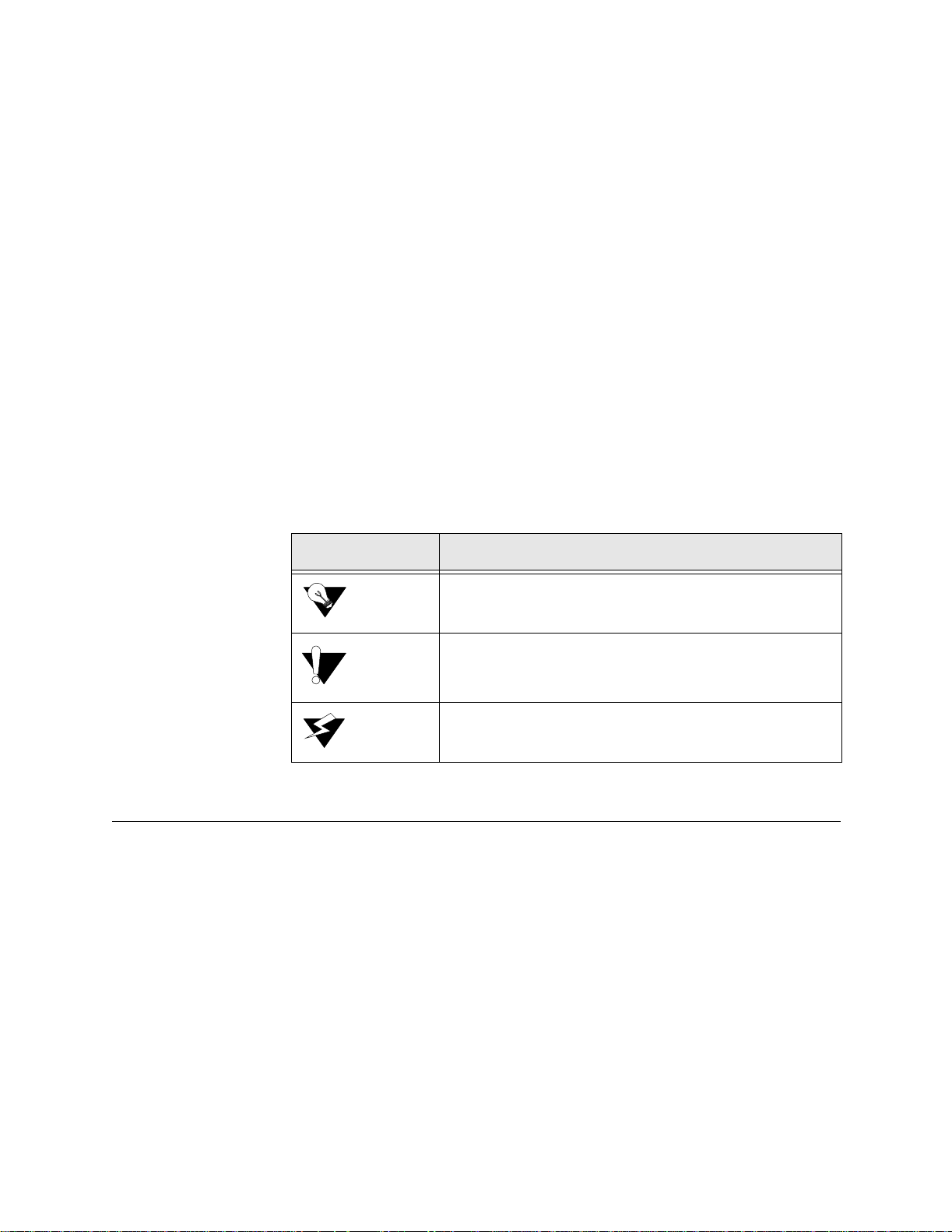
The following table lists the conventions used throughout this guide.
Convention Description
A Notice calls attentions to im portant features or inst ructions.
A Caution alerts you to s erious risk of data loss or othe r
results tha t may c ause you or t he IAD troubl e i f the warning is
not heeded.
A Warning alerts you to the ri sk of se riou s damage to the IAD
or injury and possible death to the end user.
Customer Service and Technical Support
Verilink provides easy access to customer support information through a
variety of servi ces. This section descri bes these services.
Support from Your Network Supplier
If assistance is required, contact your network supplier. Many suppliers are
authorized Verilink service partners who are qualified to provide a variety of
services, including network planning, installation, hardware maintenance,
application training, and support services. When you contact your network
supplier for assistance, have the following information ready:
• Diagnostic error messages
• A list of system hardware and software, including revision levels
xiv 7000 Series (7200p/7500p)

• Details about recent configuration changes, if applicable
Support from Verilink
If you are unable to receive support from your network supplier or want to
contact us directly, Verilink offers worldwide customer support by telephone,
e-mail, and through Verilink’s Internet Web site.
Telephone
Customer support is available 8–5 CST, Monday–Friday. To speak directly
with a Verilink customer service representative, you may dial one of the
following numbers:
•Sales and Marketing: 800-VERILINK (837-4546)
•Technical Support: 800-285-2755 (toll-fre e)
•Customer Service: 800-926-0085 ext. 3002 (toll-free)
•Out-of-W arr an ty Re p ai r FAX Num b er fo r Purch a se Or der:
256-327-2255 (local)
256-772-3388
You can request sales and marketing information or pose a technical support
question about your Verilink product by contacting us at the e-mail addresses
provided below. Verilink will respond to e-mailed requests for support during
regular business hours (8–5 CST, Monday–Friday).
•Sales and Marketing: info@verilink.com
•Technical Support: support@verilink.com
Internet
Visit Verilink’s Web site to access the latest Verilink product information,
technical publications, news releases, contact information, and more:
If this reference manual is revised to reflect code changes or other updates,
the most recent version will be posted to the Verilink Web site.
Returning a Unit to Verilink
If for any reason you must return your Verilink product, it must be returned
with the shipping prepaid, and pack aged to t he best commerci al stand ard for
electronic equipment. For in-warranty repair, Verilink will pay shipping
charges for delivery on return. You are responsible for mode and cost of
shipment to Verilink.
http://www.verilink.com
You must have a Return Material Authorization (RMA) number marked on
the shipping package. To obtain an RMA number, call Customer Service at
Preface xv

800-926-0085, extension 3002. Products sent to Verilink without RMA
numbers will be returned to the sender unopened, at the sender’s expense.
When calling Verilink for an RMA, please have the following information
available:
• Model number and serial numb er for eac h unit
• Reason for return and symptoms of problem
• Purchase order number to cover charges for out-of-warranty items (Faxed
purchase order required)
• Name and ph one number of per son we ca n contac t i f we have qu est ions abo ut
the unit(s)
The address for you to use when returning a unit to Verilink will be provided
when the RMA is issued. The standard delivery method for return shipments
is Standard Ground for domestic returns and International Economy for
international returns (unless otherwise specified).
xvi 7000 Series (7200p/7500p)

C HAPTER
1
C
HAPTER
1
I
NTRODUCTION
This chapter introduces the Verilink® 7200p/7500p integrated access device
(IAD) and describes their hardware and software. The designation
7200p/7500p denotes features and specifications common to all IAD models
in this family. Specific differences between model parameters or
specifications are noted.
The 7200p and 7500p IADs provide carrier-class reliability, advanced
networking features, and remote management capabilities that deliver
cost-effect ive value to end users and enab le service provider s to enhance
profitability.
The 7200p/7500p series IADs are ideal for service providers wishing to offer
an all-in-one device to SMB customers with key systems and PBXs (private
branch exchanges). These IADs deliver toll-quality voice service with
carrier-class reliability and provide service providers the ability to easily
migrate customers from circuit-switched to packet-based networks without
changing IADs.
Interfaces and Features of the 7200p/7500p
Data Interfaces
The data connection through the IAD supports IEEE 802.10-compliant
bridging and routing.
When the IAD is configured for routing, it supports Routing Information
Protocol (RIP) version 1, version 2, or static IP routing. The IAD complies
with RFC-1812 when interfacing with Version 4 IP routers.
The IAD can terminate the following data interfaces:
• ATM data transport via T1 per RFC 1483 or RFC 2364
• Frame Relay data transport via T1 per RFC 1490
• Frame Relay data tra nsport per RFC 1483 with Q.922 frames
Introduction 1-1

Features
The Verilink 7200p, a T1/E1 IAD, and the 7500p, an SHDSL IAD, feature up
to 23 ports for T1 and 31 ports for E1 of toll-quality voice support via a
DSX-1/PRI interface as well as a 10/100Base-T interface for high-speed data
connections. The Verilink 7200p/7500p Series delivers robust features such as
routing, bridging, NAT, DHCP, MGCP, and SIP all in one unit. This allows
service providers to provide peak performance at an affordable price. The
Universal Serial Interface (USI) delivers connectivity with most
industry-leading routers with security provided by an integrated firewall.
Remote management features allow service providers to provision, upgrade,
troubleshoot, and diagnose the 7200p/7500p products from the Central Office,
eliminating the need and expense for truck rolls to the customer premises.
Additional features include the following:
• Interope rates with DSLAMs based on Alcatel, Texas Instr uments, MetaLink,
and Globespan chip sets. These include Lucent Stinger/TNT, Nokia
Speedlink System, CDTi, AccessLa n PacketLoop, Accelerated Networks
AN-3200, CopperMountain CopperEdge, and Paradyne GranDSLAM
DSLAMs , for ex am ple .
• Provides PRI pass- through for 23 or 32 ports via T1 or E1, respectively
• Includes T1/E1 or SHDSL WAN interface
• Compatible with standards-based ATM and Frame Relay WAN protocols
• Provides dyna mic and static IP routing and bridging capabil ities
• Provides fi rewall support via IP filtering
• Offers DHCP and NAT to support IP address management
• Provides management capabilities including Telnet, SNMP, and TFTP
• Interworking feature allows Frame Relay and ATM networks to exchange
data using either FRF.5 or FRF.8 protocol
• Universal Serial Interface (USI) supports V.35 and EIA-530
The 7200p/7500p provides voice services and high-speed Internet or corporate
connectivity over T1/E1 or SHDSL.
Physical and electrical specifications for the 7200p/7500p IAD are listed in
Appendix B, Specifications.
Front Panel LED Status Indicators
The 7000 Series front panel contains five LED status indicators. Each is
described in the table below.
1-2 7000 Series (7200p/7500p)

Figure 1.1
LED Description
POWER Illuminates green when the IAD is powered on.
LAN Ill uminat es gr een whe n there is a n op erati onal L AN conn ecti on on
WAN Flashes green as the IAD is establishing a link, and illuminates
DCE Illuminates green when there is a link between the IAD and data
7000 Series Front P anel Indicators
the Ethernet port. Flashes amber when there is activity on the
Ethernet port.
solid green when there is a proper connection on the DSL WAN
port and synchronization has been achieved. Fl as hes amber when
there is activity on the WAN port.
communications equipment (DCE). Illuminates amber or blin ks
amber when the r e is activity on the DCE link.
PWR (DC Powe r
Adapter)
Console (RS-232 Serial
Port)
VOICE Illuminates green when there is voice activity on the DSX port.
When connected to a Jetstream Voice Gateway, i t r emains lit, and
blinks when there is activity on the DCE link.
Rear Panel Connectors
The 7000 Series rear panel has six connectors: PWR, CONSOLE, 10/100 LAN,
V.35/DCE, VOICE, and WAN. Each of these connectors is described below.
Figure 1.2
Connects the IAD to any 120 VAC or 90-240 VAC outlet with the use of a
DC power adapter (adapter included).
Connects the IAD to a PC using a straight-through 9-pin serial (DB9 RS-232)
cable, for the purpose of using a terminal emulator for IAD configuration and
management.
7000 Series Rear Panel Connectors
10/100 LAN
(10/100Base-T
Ethernet Port)
Connects the IAD to the local area network using a CAT-5 straight-through
Ethernet c able, or directly t o a PC fo r acces sing via Telnet (us ing a
cross-over, customer-supplied cable).
Introduction 1-3

V.35/DCE (USI Port)
The USI port is configurable for either RS-530 or V.35. When configured as
an RS-530 port, you may use a straight-through DB25 serial cable to connect
to your leased-line DTE equipment. When configured for use as V.35, Black
Box Corporation provides a cable (FA058) for conversion purposes. To
convert from RS-530 to RS-449, Black Box provides a cable EDN57J.
Contact Black Box for availability of and support for their products.
For USI port pinouts when configured as RS-530, V.35, or RS-449, refer to
Appendix B.
VOICE
Data Interfaces
WAN
Provides a DSX port (DS-1 or E1) for connection to a PBX.
The data connection through the IAD supports IEEE 802.1-compliant bridging
and routing.
When the IAD is configured for routing, it supports Routing Information
Protocol (RIP) version 1, version 2, or static IP routing. The IAD complies
with RFC-1812 when interfacing with IPV4 routers. The IAD can terminate
the following data interfaces:
• ATM data transport via SHDSL and T1/E1 per RFC 1483 or RFC 2364
• Frame Relay data tra nsport via SHDSL and T1/E1 per RFC 1490
• Frame Relay data transport per RFC 1483 with Q.922 frames
Connects through WAN interface as follows:
• 7200p − T1/E1 (uses RJ-48 conn ector)
• 7500p − SHDSL (uses RJ-11 connect or)
1-4 7000 Series (7200p/7500p)

C HAPTER
2
C
HAPTER
2
Q
UICK
This chapter describes the steps to install, connect, and set the IP address of
the 7000 Series IAD. It introduces the menu interface and describes how to
perform basic configuration for common LAN and WAN environments. It
also describes basic operations such as resetting the IAD and logging off.
In many cases, all the information you need to get an IAD up and running is
included in this single chapter. In most installations, you will proceed through
these topics in order. If your situation varies, you will find more detailed
information on installation, connection, configuration, and troubleshooting in
the chapters that follow this Quick Start Guide.
S
TART
G
UIDE
NOTICE: When the IAD prompts you for input, the current value is displayed in
Unpacking the IAD
Each IAD is packed and shipped in a durable container. Unpack and carefully
remove th e IAD f rom the package an d packi ng mate rial.
IAD Packag e
Components
Each IAD is shipped with the components listed below. As you unpack them,
note their condition and identity and compare the list with the packing list in
the package.
• AC power adapter and cord (6 feet long), or AC power cord
• Agency Comp liance informatio n sheet
• Ethernet cable (straight through), 7 feet long
• WAN cable, 7 feet long
If you note any visible damage or missing components, notify the shipping
company immediately to make a damage claim. Contact the company from
which the IAD was purchased (Verilink, or an authorized distributor) to
obtain a Return Material Authorization (RMA) for return of damaged
equipment or to order missing components. (Refer to Support from Verilink
on page xv.)
parentheses. To conveniently accept the current value, just press Enter.
Quick Start Guide 2-1

NOTICE: Verilink suggests you keep the shipping container and packing material
for future storage or shipping of the unit.
Installing the IAD
After you unpack the IAD, find a suitable location to install the unit. Ideal
locations include a computer equipment room or a telephone or wiring closet.
You can locate the IAD on a table or shelf, or it may be wall-mounted. Install
the IAD in a location that is generally protected and where it will be
undisturbed.
AC Power and Uninterruptible Power Supply
The IAD requires access to AC power (NEMA 15-3R). Make sure the IAD is
located within 6 ft of an AC power outlet. Locate the nearest power outlet and
plug in the supplied AC power adapter or AC power cord. If there is an
uninterruptible power supply on premises, plug the AC power adapter or cord
into that p ower so urce.
Ensure the power cord conveniently and safely reaches the rear panel of the
IAD whe re the po wer plug or adapt er jack is located.
NOTICE: Do not attach the AC power adapter or power up the unit at this time.
Clearance Requirements
When you install the IAD horizontally, make sure you maintain at least 2
inches of horizontal distance from other IADs or other electronic equipment
to ensure adequate ventilation and heat dissipation.
NOTICE: Due to generated heat, 7200p/7500p IADs should not be stacked on top
of each other.
Wiring Requirements
Make sure the telephone wiring, LAN, and WAN cables reach the IAD and
can be dressed in a manner that is safe for the wiring, does not pull or create
lateral stress on the connectors or ports on the rear of the IAD, and does not
present a trip hazard to personnel working in the vicinity of the equipment.
Do not connect any cables or wiring at this time.
Connecting the IAD Via a Terminal Emulator
The IAD is configured and managed from either the console or Ethernet port.
A Telnet session is usually used to access the IAD via Ethernet. After you use
a terminal emulator program via the console port (refer to DB-9 Console Port
Pin Assignments on page 6 for console port specifications) to set the IP
2-2 7000 Series (7200p/7500p)

address, you may continue to use a terminal emulator via the console port.
The factory-set default IP address is
192.168.1.254 for the Ethernet port.
NOTICE: After a period of inactivity (3 min by default), the IAD automatically
terminates console-based and Telnet sessions to maintain security. To
change this value, see Configure Console Timeout on page 3-15.
Before you can connect to the IAD via Telnet, make sure the IP address is set
correctly for this network by following these steps:
• Connect the IAD to a PC
• Log in to the IAD
• Set th e IP add re ss
Each of these steps is described in detail below.
NOTICE: Ensure the IAD and PC are both powered OFF before connecting the
console cable. If both devices are not turned off when you connect the
cables, you may place the IAD in an unstable state, and you may need
to reset one or both devices before you can perform configuration tasks.
Connecting the IAD to a PC
To connect the IAD to a PC via the console port, follow the steps below.
1 Turn off both devices and insert the male connector of a DB9 serial cable
into the console port on the IAD.
2 Insert the female connector of the cable into a serial (COM) port on your
PC.
WARNING: For Ground Start applications, ensure the IAD is properly grounded. Refer to
Figu re 2.1.
Quick Start Guide 2-3

Figure 2.1
Grounding Diagr am
3 With the console cable connected, plug the AC power adapter into the IAD.
This starts the IAD, and it executes the boot process to begin normal
operation. Verify that the Power indicator on the front pa nel illuminates.
NOTICE: For “cold start” access, the IAD default (factory-set) IP address is
192.168.1.254 on the Ethernet side.
NOTICE: As the IAD boots, it sends status messages to the console port. If you
are connected, you will see the boot sequence progress.
NOTICE: This unit should be installed by qualified service personnel only, and
must be connected to a socket outlet with protective earthing
connection.
Logging in via a Terminal Emulation Program
With a serial cable connected, follow the steps below to log in to the IAD:
1 Open a terminal emulatio n program (Hypertermin al, for example).
2 Select the COM port to which the IAD is connected.
2-4 7000 Series (7200p/7500p)
3 Type or select the settings described in the table below and save your
changes.
Setting Value Setting Value
Bits per second 19,200
Data bits 8
Parity None
Stop bits 1
Flow control None
Emulation ANSI or VT100
4 Press Enter. The IAD displays the login message:
Enter Login ID >
NOTICE: If the IAD does not respond, make sure the IAD is powered up, check
the cable and connections, and review the settings.
5 Type the default superv isor level user ID (Supervisor) (or your user ID,
if changed) and press Enter. Note that both the user ID and password are
case-sensitive. The table below lists the default user IDs and passwords.
Security Level User ID Password
User <enter> <Enter>
Network Administrator NetMan <Enter>
Supervisor Supervisor supervisor
6 The IAD displays the password message:
Enter Password >
7 Type the default password (supervisor, or your password if different)
and press Enter. If login is not successful, the IAD displays the following
message:
Invalid UserID or Password - Try again
Press any key to continue...
8 Press any key, and repeat the login sequence. If you cannot log in, call you r
support provider for assistance.
When you first log in, the IAD displays the Main menu. The menu may vary,
depending on the IAD.
NOTICE: If you are entering the menu to change a pre viously established
configuration, refer to Managing Configuration Files on page 4-1 to
save the current configuration for fast restoration in case the new
configuration does not work.
Quick Start Guide 2-5

Figure 2.2
Main Menu
Setting the Ethernet Port IP Address
Before you configure the Ethernet IP address, you should know the IP address
and subnet mask that are to be assigned to this port. They may be displayed
on the work order, or you may obtain or determine the appropriate IP address
by consulting with the network administrator.
The IAD is shipped with the IP address set to
subn et ma sk set to
255.255.255.0. To configure a port IP address, follow
192.168.1.254 and the
the steps below.
1 On the Main menu, type “2.” The IAD displays the Router Configuration
menu (Figure 2.3).
2-6 7000 Series (7200p/7500p)

Figure 2.3
Router Configuration Menu
2 Type “C” to select Configure Port IP. The IAD displays the available
interfaces. The available interfaces that display depend on the specific IAD
as shown in Figure 2.4 and Figure 2.5 below.
Figure 2.4
Figure 2.5
7500p Available Interfaces
7200p Available Interfaces
3 Type “2” to set the IP address for the Ethernet port. If the IP address is
configured for the port, the IAD displays information about the interface
and a prompt such as that shown in the example below:
4 Type the ID number of the connection you want to configure (in this case,
“0”) and press Enter.
Quick Start Guide 2-7

5 Type the new IP address, and press Enter (or press Enter to retain the
current IP address). The IAD displays the Current Subnet Mask and
prompts you for a new one.
6 Type the new Subnet Mas k (usuall y 255.255.255.0) and pres s Enter. The
IAD prompts you to select High or Normal priority.
7 To give the interface normal priority, type “N” or press Enter.
8 Type “Y” or Enter to save the new IP address and subnet mask.
9 To exit, press Escape, and then type “Y” to termin ate th e sessio n .
10 Quit the terminal emulator program.
11 Reset the IAD as described below (Resetting the IAD) for the new IP
address to be in effect.
NOTICE: When you configure the IAD, you must restart the IAD each time you
change the settings for those changes to take effect. You may make
several configuration changes before resetting.
If you plan to use Telnet for configuration tasks (Connecting via Telnet on
page 2-9), this is a good time to disconnect the serial cable from the PC and
IAD.
Setting the WAN Port IP Address
To set the WAN port IP address, follow the same procedures as those listed in
Setting the Ethernet Port IP Address on page 2-6.
Resetting the IAD
Many configuration tasks require that you reset (or restart) the IAD before the
new settings or configuration will take effect. When you use the menu
interface (or the Command Line Interface - Chapter 6, Command Line
Interface) to make changes, or change the physical characteristics of the IAD
(such as the Ethernet port MAC address), you must reset the IAD.
The IAD stores all configuration settings in memory. When it restarts, it loads
the last configuration saved before it was powered down or restarted. When
restarting is required, it will be included as a step in the configuration process.
You can reset the IAD in one of the two following ways:
To reset the IAD from the menu:
1 On the Main menu, type “R” to select Reset System.
2 Type “R” again at the prompt. This resets and starts the IAD with your
new settings.
3 To log in again, enter your user ID and password.
To reset the IAD manually, unplug the power adapter from the IAD and then
plug it back in.
2-8 7000 Series (7200p/7500p)

CAUTION: Be sure to complete your task and return to the Main menu before
Connecting via Telnet
To manage the IAD via the LAN (or Intranet), you must set an IP address for
the Ethern et port be fore you can use Telnet t o access t he IAD .
Although you can also access the IAD using Telnet via the WAN (provided a
management DLCI or PVC is configured along with a WAN IP address), this
section describes connecting via the LAN. For information about setting the
IP address of the WAN port (Refer to Managing Configuration Files on page
4-1.)
If you configure a RADIUS Client, you must use a RADIUS-authenticated
User ID/password for Telnet access. If the RADIUS server or the connection
to the RADIUS Client goes down, Telnet access will not be permitted. For
information about configuring a RADIUS client (Refer to RADIUS Client
Settings on page 3-4.)
Running Telnet
restarting the IAD manually. Resetting the IAD terminates all
telephone calls and computer sessions in progress. You should ensure
there are no services being rendered before resetting the IAD.
Before you use Telnet to log into the IAD, ensure the IAD and your PC are
connected to the same network via straight-through Ethernet cables (or
directly connected via a cross-over cable), and you know the IP address of the
IAD. Both devices must be on the same subnet.
To log in, follow the steps below.
1 Run Telnet on your PC.
2 Type the IP address of the Ethernet port (refer to Setting the Ethernet Port
IP Address on page 2-6), click Connect and then press Enter to gain the
attention of the IAD. The IAD responds by prompting you to enter your
Login ID.
3 Type your user ID and press Enter. The IAD will then prompt you to enter
your Password.
NOTICE: After a period of inactivity (three minutes by default), the IAD
automatically terminates console-based and Telnet sessions to maintain
security. To change this value, refer to Configure Console Timeout on
page 3-13.
NOTICE: Default user IDs and passwords are listed in the table on page 2-5. For
information on security levels, and user ID and password management
see IAD Security on page 3-1.
4 Type your password and press Enter to display the Main menu (Figure 2.2).
Quick Start Guide 2-9

NOTICE: The user ID and password transmit as clear text, which may be
captured by unauthorized individuals. If you are concerned with
network security, you may not want to use Telnet to configure the IAD.
Navigatin g th e IA D
Menu Interface
Entering Settings and
Values
Using Default or
Current Values
Menus in the IAD configur ation sys tem are ar ranged hierarch ically. Th at is,
you select single-key options to navigate down to display specialized menus
and specific tasks, and press the Escape key successively to return back to
menus higher in the interface.
The specific menus, submenus, and commands that display depend on the
interfaces for the specific IAD, the options configured, and the security level
you use to log in.
To select a menu item, type the option displayed to the left of the item.
Although character options are displayed in upper case, the IAD accepts both
upper- and lower-case options. It is not necessary to press Enter after typing
the selection − the IAD immediately responds with a request for input or
another menu for more options.
For a hierarchical map of the Main menu, its menus and commands, see
Appendix A.
When the IAD requests input for a setting or configuration value, type it at
the prompt. Press the Enter key to terminate the input and proceed to the next
step. The IAD responds with error messages if a value is incorrect, or it
displays the current menu so you can continue with related tasks.
The IAD displays a default or current value in parentheses immediately to the
right of ea ch mess age, just t o the le ft of the command prompt . To acc ept this
value, press the Enter key.
For example, when the prompt asking you to enter a new Subnet mask
displays, you may press Enter to cause the IAD to set
Subnet Mask value. Using the Enter key to skip through default or current
values often speeds the process of proceeding through a family of input steps
to more quickly reach the input step where you wish to change a value.
Exiting the Menu
Interface
To exit the menu interface, return to the Main menu using the Escape key,
and press Escape one more time. When the IAD asks you to confirm, press
“Y” to exit or press Return to accept the default value “N” to cancel the exit.
NOTICE: After exiting, you can quit the terminal emulator or Telnet session. If
Basic IAD Configuration
Each IAD is shipped with a default configuration set in the file default.st.
Once you make any changes to your IAD, a new file is created to store the
new configuration—config.st—to preserve the default settings.
255.255.255.0 as the
you made changes to the configuration that require resetting the IAD,
be sure to do so before exiting.
2-10 7000 Series (7200p/7500p)

After you have configured the IAD for correct operation in a customer’s
premises, the current system settings in the config.st file may be saved as the
default configuration file (custdef.st), and you may choose to set the IAD to
boot from this file each time it is reset. You may also copy this file to a PC or
TFTP server for downloading to other identically configured IADs. Once you
have replaced the original custdef.st file, you cannot retrieve it. Consider
copying the custdef.st file to a safe location before replacing it.
To perform basic IAD configuration, follow the steps below.
NOTICE: Only the 7200p supports DLCIs in the WAN configuration.
• Configure the LAN IP address, if not already completed (page 2-6).
• Configure each of the WAN options and the DSLAM profile (page 4-1 and
the pages following 4-1).
• Create and confi gure at least one DLCI (page 4-23) or PVC (page 4-15) for
data traffic and set the WAN IP add re ss (p age 2-6).
• Configure static or default route (page 4-29) or enable bridging (page 4-46)
for all data traffic.
• Create and configure a DCLI (page 4-23) or PVC (page 4-15) for voice
where required, and select appropriate voice gateway settin gs (page 4-54).
• Reset the IAD (page 2-8) to enable all configuration changes.
NOTICE: You must reset the IAD after configuring IP addresses before you may
add routes.
Connecting LAN, WAN, and Telephones
This section details how to connect the IAD to the computer and telephone
systems the IAD is intended to support.
Before proceeding, make sure you have an appropriate serial cable for your
PC, identify the LAN switching equipment where you’ll connect the IAD,
identify the telephone cables, and verify that WAN service is installed and
configured by the service provider.
When you’ve completed this section, reset the IAD so it can synchronize
these physical connections.
Ethernet LAN Connection
The Ethernet LAN port on the rear of the IAD is an RJ-45 jack for
10/100Base-T Ethernet cables. If the IAD is intended to act as an Internet
gateway for the LAN in the customer’s premises, connect the IAD to the
switch, hub, or router using an Ethernet straight-through cable.
NOTICE: You may temporarily connect the IAD directly to a PC for Telnet
configuration (without going through a hub or router). The Ethernet
Quick Start Guide 2-11

receiver automatically detects the type of Ethernet cable
(customer-supplied).
WAN Connections
WAN connections vary, based on the WAN interface on your IAD. The
7500p is an SHDSL-equipped IAD and uses an RJ-11 connector to connect to
the rear panel WAN connection. To make the connection, plug the SHDSL
cable into the RJ-11 WAN connector. (Refer to page B-6.) The 7200p is a
T1/E1-equipped IAD and uses an RJ-48 connector on the IAD rear panel for
WAN connection. To make the connection, plug the cable from the ATM
network into the RJ-45 WAN connector. Refer to page B-6 to see the pinouts
for the T1/E1 connection.
USI Connection
If your IAD is equipped with a USI port, you may connect it now. Located on
the rear panel, the port uses a shielded, DB25 connector. The connector is
DCE − data is transmitted on the receive pin and received on the transmit pin.
The V.35 and EIA-530 interfaces use different voltage levels. You must
supply the appropriate cable for each interface. Refer to Appendix B for
pinout connections.
Confirming Proper Setup
When you have completed the tasks in this chapter, reset the IAD and test
your configuration for proper data and voice operation. Reset the IAD
(page 2-8) to synchronize the physical connections using the verification
procedure described in Figure 8.
2-12 7000 Series (7200p/7500p)

C HAPTER
3
C
HAPTER
3
A
DMINISTRATION
This chapter describes how to control security to your IAD, validate users
using a RADIUS Server, configure SNMP via IP or AAL2 Embedded
Operations Channel (EOC), upgrade IAD software, and perform other general
and utility-oriented tasks.
NOTICE: When the IAD prompts you for input, the current value is displayed in
parentheses. To conveniently accept the current value, just press Enter.
IAD Security
NOTICE: After setting IAD Security pa rameters, you m ust reset the IAD
(page 2-8) for the new settings to take effect.
To maintain IAD security, the IAD provides multi-level login access using a
single user ID and password, which you can set at the following levels:
• User
• Network Administr ator
• Supervisor
The user ID at the User secu rity level ma y be modified , but the user ID at the
Network Administrator and Supervisor levels may not.
The password for each security level may be changed. Although you may use
the same password for all security levels, Verilink recommends that you use a
different one for each level. The table below lists the privileges available at
each secur ity level.
Administration 3-1

Security level Privileges
Supervisor This user level is the highest level. Users who log in as
Supervisor have full access to all IAD features (menu
and command line interface , including changing User
security level, user ID, and any level passwords, plus
complete IAD configuration capability.
Network Administrator At this level, users may perform tas ks that alter the
network settings of the IAD, pl us are abl e to acces s to all
data networking conf iguration menus, and ca n update
routing and bridging information and status.
This user can change the password at this leve l, and also
can change the User-level User ID and password, and
can access all display-only menus.
At this level, users user cannot modify WAN or LAN
settings, alt er derived timing, use the Command Line
Interface, or modify voicepath settings.
User At this level, the user has access to displ ay-only menus,
and can view the current configuration, interfa ce, and
media statistics, routing and bridging information, and
status. The user may ch ange this level User ID and
password, but cannot make or save any changes to the
configuration of the IAD.
To maintain IAD security, a user with Supervisor privileges should modify
the User security level user ID and passwords for both User level and
Network Administrator level prior to placing the IAD into production.
The table below lists the default values for the user IDs and passwords:
Security Level User ID Password
User <Enter> <Enter>
Network
Administrator
Supervisor Supervisor supervisor
The user ID and password may contain up to 17 alphanumeric characters.
These values are case sensitive; spaces and punctuation characters are not
allowed.
The IAD can store only one user ID and password at each security level.
Password Configuration Menu
To access the Password Configuration menu, type “8” (Configure Login) on
the Main menu.
NetMan <Enter>
3-2 7000 Series (7200p/7500p)

Figure 3.1
Password Configuration Menu
Change User ID
To change the user ID for the User security level (the only security level that
allows the user ID to be changed), follow the steps below.
1 Type “1” to change t he user ID for the User security level.
2 Type the new User ID (up to 17 characters) and press Enter. The IAD
informs you that the user ID has been updated.
3 Reset the IAD.
Including User IDs and Passwords in Config Files for Multiple Site
Distribution
If you create master configuration files for distribution to multiple IADs, you
may include the user ID and passwords directly in the configuration file to
reduce configuration tasks.
NOTICE: When the user ID and passwords are stored in a configuration file, the
IAD saves the configuration file immediately upon rebooting, without
requiring the log-in process. The user ID and passwords are stripped
from the configuration file before saving to prevent a security risk.
Using a text editor, update the config file by adding the following attributes in
the [user] category:
userid={string}
password={string}
netman-password={string}
support-password={string}
The password parameter is for User-level access, the “netman” password is
for Network-Administrator-level access, and the “supervisor” password is for
Superviso r-level access.
Administration 3-3

Change User Password
To change a password at any security level, you must sign on at or above the
security level you’re changing and follow the steps below.
1 Type “2”, “3”, or “4” on the Password Configur ation m enu to chan ge the
password for the selected level.
2 Enter the password for the current level.
3 Enter the new password after the prompt, or press Enter to enter a null
password.
4 Enter the new password (or Enter) again, to confirm the change.
The IAD immediately updates the password. The next time you log in at that
level, the new password will be in effect.
NOTICE: You cannot use the Escape key to exit the password update command.
To exit, deliberately enter an incorrect password at the confirmation
step, or reset the IAD.
RADIUS Server Settings
You can use a RADIUS Server to determine the validity of unknown user
ID/password pairs in your IAD. Verilink does not provide a RADIUS Server;
the user must provide a RADIUS Server to use this feature. For more
information on RADIUS Server, see RFC 2865.
If you co nfigure a RADIU S Server, the IAD must b e able to succes sfully
connect to the RADIUS Server. This requires WAN configuration, IP
configuration, static or default routes, and other configurations for your
network. Additionally, you must use a RADIUS-authenticated user
ID/password for Telnet access. If the RADIUS Server becomes inoperative,
Telnet access will not work.
To use a RADIUS Server, set the following options:
• Change the primary or secondar y RADIUS Server Address
• Change the primary or secondar y RADIUS Server Encryption Secret
• Display RADIUS Server Configuration
Each of these settings is described below.
Change Primary (or Secondary) RADIUS Server Address
To change the primary or secondary RADIUS Server address, follow the steps
below.
1 Type “5” on the Password Configuration menu to se lect Change Primary
RADIUS Server Address or Type “7” to select Change Secondary
RADIUS Server Address. The IAD displays the current Radius Server and
prompts you to enter a new one by IP Address or name.
2 Type the IP address in one of the following formats and press Enter.
3-4 7000 Series (7200p/7500p)

IP address
Fully-qualified host and domain names
(for example: radius.Verilink.com—maximum 42 bytes)
NOTICE: If you enter host and domain names, you must configure the IAD as a
DNS client (see page 4-36).
3 Reset the IAD.
Change Primary (or Secondary) RADIUS Encryption Secret
To change the primary or secondary RADIUS encryption key, follow the
steps below.
1 Type “6” on the Password Configuration menu to se lect Change Primary
RADIUS Encryption Secret or type “8” to change Secondary RADIUS
Encryption Secret. The IAD displays the current Radius Encryption Secret
and prompts you to enter a new one.
2 Type the new encryption key and press Enter.
3 Reset the IAD.
Display RADIUS Configuration
To display the current RADIUS Server configuration, follow the steps below.
1 Type “9” on the Password Configuration menu to select Display RADIUS
Configuration. The IAD displays the following information :
Primary RADIUS Server:
Primary RADIUS Secret:
Secondary RADIUS Server:
Secondary RADIUS Secret:
Disable RADIUS Configuration
To disable the RADIUS Server configur ation, type “X” on the Password
Configuration Menu (Figure 3.1) . The IAD disables both the Primary and
Secondary RADIUS Server configur ations.
Setting Up SNMP
NOTICE: After updating SNMP settings, you must reset the IAD (refer to
You can enable SNMP over IP and/or EOC (when the voice gateway is
AAL2/LES CAS or ELCP). By default, the IAD is configured with SNMP
disabled. When SNMP is enabled and the settings are configured, you can use
SNMP to remotely manage the IAD by getting and setting IAD values and
monitoring IAD events.
page 2-8) for the new settings to take effect.
The IAD supports the following SNMP settings:
Administration 3-5

• System Contact
• System Name
• System Location
• SNMP Community
• SNMP Trap Host IP Address
The following SNMP traps are supported:
• System reset
• Attempts to acce ss SNMP with an invalid community name
• Starting and stopping TFTP within SNMP
The IAD supports MIBs for RFCs 1213, 1317, 1406, 1493, and 1463 as well
as af-vmoa-0174 (AAL2/LES MIB).
SNMP Configuration Menu
To display the SNMP Configuration menu, type “7” on the Main menu. Each
of the menu’s configuration options is described below.
Figure 3.2
NOTICE: The strings you ent er in SNMP are not case se nsitive.
SNMP Configuration Menu
Enable/Disable SNMP via IP
To Enable or Disable SNMP via IP, follow the steps below.
1 Type “E” on the SNMP Configur ation menu t o ena ble or di sable SNMP via
IP. The IAD displays the current status of SNMP.
2 To enable SNMP, type “E” or “D” to disable. The IAD saves the
configuration (if changed).
3-6 7000 Series (7200p/7500p)

3 Continue with other SNMP settings, or press Escape to return to the Main
menu.
4 Reset the IAD.
Enable/Disable SNMP via EOC
To Enable or Disable SNMP via EOC, follow the steps below.
1 Type “F” on the SNMP Configur ation menu t o ena ble or di sable SNMP via
EOC. The IAD d isp lay s the current status of SNMP .
2 To enable SNMP, type “E” or type “D” to disable. The IAD saves the
configuration (if changed).
3 Continue with other SNMP settings, or press Escape to return to the Main
menu.
4 Reset the IAD.
Enable SNMP via Both IP and EOC
To Enable SNMP via Both IP and EOC, follow the steps below.
1 Type “A” on the SNMP Configuration menu to enable SNMP via IP and
EOC. The IAD saves the configuration.
2 Continue with other SNMP settings, or press Escape to return to the Main
menu.
3 Reset the IAD.
Disable SNMP via Both IP and EOC
To Disable SNMP via both IP and EOC, follow the steps below.
1 Type “B” on the SNMP configuration menu to disable SNMP via IP and
EOC. The IAD saves the configuration.
2 Continue with other SNMP settings, or press Escape to return to the Main
menu.
3 Reset the IAD.
Configure System Contact
To config ure the Sy stem C ontact, fol low th e steps bel ow.
1 Type “P” on the SNMP Configuration menu to configur e system contact
(up to 39 alphanumeric characters). The IAD displays the current system
contact and prompts you to enter a new one.
2 Type the name of the new contact person or department and press Enter.
The IAD save the configuration.
3 Continue with other SNMP settings, or press Escape to return to the Main
menu.
4 Reset the IAD.
Administration 3-7

Configure System Name
To config ure the Sy stem N ame, foll ow the s teps belo w.
1 Type “N” on the SNMP Configuration menu to configure the system name
(up to 39 alphanumeric characters). The IAD displays the current system
name and prompts you to enter a new one.
2 Type the new system name and press Enter. The IAD saves the
configuration.
3 Continue with other SNMP settings, or press Escape to return to the Main
menu.
4 Reset the IAD.
Configure System Location
To configure the System Location, follow the steps below.
1 Type “L” on the SNMP Configuration menu to configur e the system
location (up to 39 alphanumeric characters). The IAD displays the current
system location and prompts you to enter a new one.
2 Type the name of the new server location and press Enter. The IAD saves
the configuration.
3 Continue with other SNMP settings, or press Escape to return to the Main
menu.
4 Reset the IAD.
Configure SNMP Trap Host IP Address
To configure the SNMP Trap Host IP Address, follow the steps below.
1 Type “T” on the SNMP Configuration menu to select Selec t Configure
SNMP Trap Host IP Address of the system setup for trap operations. The
IAD displays the current IP addre ss and prompts you to enter a new one.
2 Type the IP address and press Enter. The IAD saves the configuration.
3 Continue with other SNMP settings, or press Escape to return to the Main
menu.
4 Reset the IAD.
Enable/Disable SNMP Traps via EOC
To Enable or Disable SNMP Traps via EOC, follow the steps below.
1 Type “U” on the SNMP Configuration menu to enable or disabl e SNMP
traps via EOC. The IAD displays the current status.
2 To enable traps via EOC, type E. To disable them, type D. The IAD saves
the configuration.
3 Continue with other SNMP settings, or press Escape to return to the Main
menu.
3-8 7000 Series (7200p/7500p)

4 Reset the IAD.
Configure Restart Trap Maximum Delay
To configure Restart Trap Maximum Delay, follow the steps below.
1 Type “D” on the SNMP Configuration menu to configur e the restart trap
maximum delay time. The IAD prompts you to input a new value.
2 Type the new value in seconds and press Enter. The IAD saves the
configuration.
3 Continue with other SNMP settings, or press Escape to return to the Main
menu.
4 Reset the IAD.
Defining Different SNMP Version 3 Categories
SNMP is supported via Internet Protocol (IP) and the Loop Emulation System
Embedded Operation Channel (LESEOC). The LESEOC interface is only
available with either the AAL2/LES CAS or ELCP voice gateway. This
interface allows the voice gateway to monitor and control specific IAD
operational parameters.
NOTICE: Some voice gateways with this feature require a read-write community
name of LESEOC to be configured in the IAD.
The SNMP Configuration menu is accessible from the Main menu. You may
enable SNMP via IP, EOC, or both. Traps may be sent to a configurable IP
address, the EOC, or both. The System Contact, System Name, and System
Location may also be con figured. T hese valu es are acc essible via the R FC
1213 MIB.
SNMP 3.0 requires the configuration of six data structures on the SNMP 3.0
menu (Figure 3.3), which is accessible from the SNMP Configuration menu.
Menu options are available to configure a default set of structures, which will
allow SNMP 1.0 or SNMP 3.0. Choose Option 3 on the SNMP 3.0
Configuration menu to set a simple default configuration.
Administration 3-9

Figure 3.3
SNMP V3 Configurat ion Me nu
Two SNMP “community entries” are generated: public (read-only
community), and a read-write community. Since a read-only community of
public is the default for all SNMP implementations, you are encouraged to
reconfigure the first community entry to a more secure value.
The “targ et entries” specify who may access the IAD via SNM P. The first
entry, named “everyone,” allows access from the entire Internet. Entries are
added if an IP trap host is configured, or if EOC access is configured. For
example, if you want only IP addresses 1.2.3.0 through 1.2.3.255 to have
SNMP access to the IAD, you will reconfigure the target entry with the
address of 1.2.3.0, and the mask 255.255.255.0. Note EOC access is specified
by the reserved IP address 255.255.255.255.
The “group entries” specify which version of SNMP to allow: 1.0 or 3.0 (user
security m odel).
The “acc ess entry” specifi es which v ersion of SNMP to allow, the sec urity
level (MD5 authorization encryption), and which views are accessible.
The “view entry” specifies which portion of the MIB is accessible or not
accessible. For exa mple, it is possible to cre ate a view to allow access t o the
ATM Forum LES MIB from the EOC, and allow the entire MIB to be
accessible from an I P locatio n.
The “user entry” applies to SNMP 3.0 only. This is where you configure the
MD5 authorization encryption password.
3-10 7000 Series (7200p/7500p)

LAN Configuration Menu
The IAD LAN port may be set for full duplex Ethernet operation if your IAD
is set up as a router (page 4-29). Full duplex mode allows simultaneous
transmission and receipt of Ethernet packets.
On the Main menu, type “6” (Configure LAN) to display the LAN
Configuration menu.
Figure 3.4
LAN Configuration Menu
Establishing LAN Speed and Duplex Mode
1 Type the option number of the speed and duplex mode. The IAD saves the
configuration.
2 Press Escape to return to the Main menu.
3 Reset the IAD.
NOTICE: Full duplex Ethernet operation is controlled by the switch. If the switch
is set to full duplex, you may enable it in the IAD. If you enable
full-duplex Ethernet in the IAD when the switch is operating in normal
half-duplex mode, your IAD will not communicate on the LAN.
You can display the current LAN settings using the Display Current
Configuration command in the Reports menu (page 5-1).
Upgrading the System
Periodically, Verilink may provide new software that you will download to
the IAD to upgrad e the sys tem. You must u se TFTP t o perform the f ile
transfer when upgrading the entire system.
Administration 3-11

NOTICE: Some gateways directly support file transfer as a means of upgrading
IADs. For information, refer to the Voice Gateway manufacturer’s
operating manual.
To use TFTP, you must configure both the IAD and the computer that
contains the TFTP Server program, a program for the computer that you
license separately.
Using TFTP Servers via LAN or WAN
Before the IAD can access a LAN or Intranet-based TFTP server, you must
configure the IP address of the Ethernet port (page 2-6) on the same subnet as
your TFTP server, and the IAD must be connected to the LAN.
To access a WAN-based server, you must configure the T/E1 or SHDSL
Interface with a management DLCI or PVC and a WAN IP address. For
information about setting the IP address of the WAN port, see Setting the
WAN Port IP Address on page 2-8 or WAN Configuration Menu on page 4-4.
Copying the Source Files
Typically, you will receive two ZIP files (a core ZIP file and an application
ZIP file) for each upgrade.
First, extract each file into a single directory on your PC. Then, set the
directory as the path that the TFTP Server will use to send files to the IAD
(often identified as upload/download or outbound directory).
Upgrading via TFTP
If your TFTP Server is not running, start it now and note the IP address of the
computer it is running on. To upgrade the IAD software, follow the steps
below.
1 On the Main menu, type “9” to display the Utilities menu (see Figure 3.6).
2 Type “X” to display the File Transfer menu.
Figure 3.5
File Transfer Menu
3 Type “X” to update the entire syste m (you must use TFTP).
4 Respond by typing “Y” to continue.
3-12 7000 Series (7200p/7500p)

5 The IAD prompts you to enter the IP address of the TFTP Server.
6 Type the IP address of the TFTP Server and press Enter.
As file transfer progresses, the IAD reports the status of each file being
copied. Two files − acos.bin and boot.bin − will only be copied if they match
the platform to guard against loading incorrect system files onto an IAD.
NOTICE: If the IAD cannot locate the first file to download (typically
Upon completion, the IAD reports the success or failure of each file transfer,
and then reports the completion of file transfer and resets.
Verifying the Upgrade
To verify that the files downloaded successfully after being transferred,
observe the boot sequence. The IAD displays the software version in the
Verilink banner.
You may also display the current configuration (page 8-2) to validate the
firmware version.
release.dat), the update will fail. Make sure you have assigned a valid
IP address and subnet mask, and you’re on the same subnet as the
TFTP Server. Use the Ping command to ping the IAD and try again.
Utilities Menu
The Utilities menu contains utility commands, including several menus to
upgrade IAD software and support ACOS application development.
To display the Utilities menu, type “9” on the Main menu. Option “U” will
display the USI port menus.
Administration 3-13

Ping Utility
Figure 3.6
Each option on this menu is described in detail below.
Utiliti es Menu
To check for a device on a network, follow the steps below:
1 Type “P” on the Utilities menu.
2 Type the IP address or complete host name. If you enter a host name, you
must enter the domain name also (i.e., mycomputer.mydomain.com).
3 Type the ping packet size.
4 Type the number of times to ping (0 causes Ping to run until you press
Escape).
The IAD displays the following report:
Trace Route
1 Type “T” on the Utilities menu and press Enter .
3-14 7000 Series (7200p/7500p)

2 Type the IP address or complete host name. If you enter a host name, you
must also enter the domain nam e (i.e., mycomputer.mydomain.com). The
IAD displays each hop, as shown in the following sample report:
Configure Console Baud Rate
To set the console port baud rate (for connecting to Hyperterminal via a serial
cable), fo llow these steps:
1 Type “Z” on the Utilities menu to display the following menu:
2 Type “0” to reset the baud rate to the default ( 19200 bps), or select a
specific baud rate and press Enter.
3 Reset the IAD to use the new console port settings. Be sure the terminal
settings are the same as the console port settings.
NOTICE: The new baud rate table will take effect only after you either recycle the
power or reset the IAD.
Configure Console Timeout
To maintain security, you can set the amount of time a console or Telnet
session remains alive before termination due to inactivity. To set the timeout
period, follow these steps:
1 Type “V” on the Utilit ies m enu to displ ay the C onsole Ti meout Status a nd a
prompt for you to enter a new Timeout value or disable the Timeout.
2 Type a value between 0-60 minutes (default 3) and press Enter or type “0”
(zero) to disable the Timeout feature.
CAUTION: When the Timeout value is set to zero, sessions will stay alive
indefinitely, and may pose a security risk. Quitting a terminal
Administration 3-15

emulator session does not terminate the console port session. You
must log off before quitting to avoid creating a security risk.
Reset or Reload ACOS from FLASH
When you perform a hard reset, the IAD resets, using all values set during the
active session and reloads ACOS from flash memory. To perform a hard
reset, follow these steps:
1 Type “R” on the Utilities menu. The IAD displa ys the following:
Sure you want to do a Hard Reset? (Y/N)->
2 Enter “Y” to immedia tely pe rform a hard reset a nd reload ACOS, repl acing
it.
Set System Default
You may set the IAD to boot from the previously saved custom configuration,
or boot from the factory-supplied configuration file as described below.
1 Type “D” on the Utilities menu. The IAD displa ys the following menu:
Figure 3.7
System Default Menu
2 Type “1” to set the previously saved cus tom configuration file as the boot
file
—or—
Type “2” to set the default.st config file as the boot file.
3 The IAD displays a warning and asks you to confirm your decision.
4 Type “Y” to confirm the process. The IAD updates the setting and displays
the Utility menu.
5 Reset the IAD to reboot with the new config file.
Save System Settings as Defaults
To save the current configuration as the custom default or backup
configuration, follow the steps below.
1 Type “W” on the Utilities menu. The IAD displa ys a warni ng and asks you
to confirm your decision.
2 Type “Y” to delete the default.st file and save the current configur ation
(stored in config.st) as custdef.st, a custom default co nfiguration file.
The IAD saves the custom configuration file and displays the Utility menu.
3-16 7000 Series (7200p/7500p)

Display Event L o g
To display the event log, type “E”. T he IAD displays t he event log (sam ple
shown):
Figure 3.8
Press any key to page through the log.
Event Log
Clear “Last Reset Reason”
Under cert ain circum stances, th e IAD is able to determin e the reason the IAD
was reset. This information is stored and displayed when the IAD reboots, and
is also displayed on the Current Configuration screen (Displaying the Current
Configuration on page 8-2), when known.
After the reset reason is noted, you can delete the currently stored reset reason
from the IAD. To do so, type “A” on the Utilities menu. The IAD deletes any
existing reset reason, and displays the Utility menu.
Administration 3-17

Time Zone Menu
The Time Zone menu () is used to help set the current time. When the IAD is
reset or the power is cycled, the IAD will use Network Timing Protocol
(NTP) to obtain the current time.Tim e Zone M enu
In the Time Zone menu, you may specify your time zone so the time
displayed on statistics screens will be your local time. To set, type “O” and
then type in your time zone offset from Greenwich Mean Time (GMT). For
example, for Pacific Standard Time (PST), you would type in an offset of
“−8.” Type “N” to enter a text label for your time zone.
File System Menu
The File System menu contains commands to manage files on the IAD. To
display the File System menu, type “F” on the Utilities menu.
Figure 3.9
To perform a task, type th e option and r ead ho w to pr oceed b y refer ring to the
appropriate section below.
File System Menu
Directory of all Files
To display the files stored in flash memory, type “D” on the File System
menu. The IAD displays the files and size. Page down the list by pressing any
key. The IAD displays the amount of free memory at the end of the list.
Copy File
To duplicate a file with a new name, follow the steps below.
3-18 7000 Series (7200p/7500p)

1 Type “C” on the File System menu. The IAD prompts you for the name of
the source file.
2 Type the name of the existing file (including the suffix) and press Enter.
The IAD prompts you for the name of the new file.
The IAD copies and saves the file with the new name. When the operation is
com ple te, t he I AD d isp lay s the Fi le S yste m menu .
Rename File
To rename a file, f ollow th e steps be low.
1 Type “R” on the File System menu. The IAD prompts you for the name of
the file to rename.
2 Type the new name of the file (including the suffix) and press Enter. The
IAD prompts you for the name of the new file.
The IAD renames the file with the new file name. When the operation is
complete, press any key to display the File System menu.
CAUTION: Renaming files is permanent, and may render the IAD inoperative or
unable to boot.
Delete File
To permanently remove a file, follow the steps below.
1 Type “X” on the File System menu. The IAD prompts you for the name of
the file to delete.
2 Type the name of the file (including the suffix) and press Enter .
The IAD deletes the file. When the operation is complete, the IAD displays
the File System menu.
CAUTION: Deleting files is permanent, and may render the IAD inoperative or
unable to boot.
Format File System Drive
Reformatting the file system permanently removes all files in the IAD. This
command is reserved for use by Verilink network engineers.
WARNING:The Format File System command is reserved for use by Verilink
engin eer s. Us e of th is co mm an d per ma nentl y er ases ever y fil e in th e IA D,
rendering it inoperative.
Administration 3-19

Space Left in File System
To display the am ount of fre e spac e in the f ile system (flash memory) , type
“S” on the File System menu. The IAD displays the free space.
File Transfer Menu
The File Transfer menu allows you to transfer groups of files to or from the
IAD. To display the File Transfer menu (see Figure 3.5 on page 3-12), type
“X” on the Utilities menu. To perform a specific task, type the option and
proceed to the corresponding section below.
Load Boot ROM
1 Type “B” on the File Transfer menu to download the Boot ROM to the file
system on the IAD.
Figure 3.10
File Transfer Me thod Menu
2 Type “1” to use TFTP, or “2” to use XMODEM to transfer the file to the
IAD.
3 The IAD displays the prompts you for the IP address of the TFTP server.
4 Type the IP address of the TFTP server and press Enter.
5 The IAD displays the following prompt for the file name to transfer:
6 Type the name of the file and press Enter. To exit without transferring the
file, press Escape or Enter without typing the file name.
7 When XMODEM is selected, if the file is not located, the IAD prompts you
for the file transfer speed .
8 The IAD transfers the file via TFTP or XMODEM.
Perform a hard res et to re set the IAD (page 3 -16) whe never you load a new
version of boot ROM. Performing a normal reset is not recommended.
Update ACOS [acos.bin]
1 Type “O” on the File Transfer menu to display the File Transfer Method
menu and download Verilink’s Atla s Communications Operating System
(ACOS) to the f ile sy stem i n Flash mem ory on t he IAD. The fil e is stor ed on
the IAD as acos.bin. The IAD displays the File Transfer Method menu.
2 Type “1” to use TFTP, or “2” to use XMODEM to transfer the new
version of ACOS to the IAD. If you select XMODEM, proceed to step 5
below.
3-20 7000 Series (7200p/7500p)

3 The IAD prompts you to enter the IP address of the TFTP server.
4 Type the IP address of the TFTP server and press Enter. The IAD displays
the following prompt for the fil e name to transfer:
5 Type the name of the file and press Enter. To exit without transferring the
file, press Esc ape or Enter without typi ng t he f ile name. When XM ODEM is
selected, if the file is not located, the IAD prompts you for the file transfe r
speed. The IAD tra nsf ers the fi le via TFT P or X MO DE M .
Perform a hard res et (page 3 -16) to reset the IAD whe never you load a new
version of ACOS. Performing a normal reset is not recommended.
Update Entire System
1 Type “X” on the File Transfer menu to update the IAD by transf erring the
upgrade package of files pr ovided by Ver ilin k. The number a nd type of f iles
varies by IAD. The IAD uses TFTP to download files sequentially to the
IAD. The IAD displays a confirmation prompt.
2 Type “y” to continu e, or an y other characte r to escape. The IAD prompt s
you for the IP addr ess of the TFTP Server.
3 Typ e the IP add re ss of the TF TP s erver and press Enter. The IAD tr ans fers
each of the system files.
When the file trans fers are co mplet e, perfor m a hard reset (pag e 3-16) t o
restart the IAD. Performing a normal reset after updating the system is not
recommended.
File Transfer Utilities
To perform file transfers for any files, type “A” on the File Transfer menu to
display the File Transfer Method menu to download a file to the file system in
the IAD. The IAD displays the File Method menu.
1 Type “1” to use TFTP, or “2” to use XMODEM to transfer the file to the
IAD. If you select XMODEM, proceed to step 3. The IAD prompts you to
enter the IP address of the TFT P server.
2 Type the IP address of the TFTP server and press Enter. The IAD displays a
prompt for the file name to transfer.
3 Type the name of the file to transfer and press Enter. To exit without
transferring the file, press Escape or Enter without typing the file name.
When XMODEM is selected, if the file is not located, the IAD prompts you
for the fi le transfe r speed.
After the IAD transfers the file via TFTP or XMODEM, reset the IAD
(page 2-8) to use the new file. If you transfer acos.bin using this option,
perform a hard rese t (page 3-16).
Administration 3-21

TFTP Server Menu
Type “T” on the File Transfer menu to display the TFTP Server menu
(Figure 3.11) where you can enable and disable read access, write access , and
console output.
Figure 3.11
TFTP Server Menu
The IAD displays the current settings directly below the menu heading. To
successively enable or disable access or output, execute the option again. The
IAD saves the configuration and displays the menu. When the options are set
correctly, re set th e IAD for the chang es to ta ke effec t.
3-22 7000 Series (7200p/7500p)

Introduction
C HAPTER
4
C
HAPTER
4
C
ONFIGURATION
This chapter describes WAN, Router, Bridge, Voice Path, Firewall, DHCP
Server, and NAT Configuration.
NOTICE: When the IAD prompts you for input, it displays the default or current
value in parentheses. To conveniently accept this value, just press Enter.
NOTICE: You must reset the IAD (refer to page 2-8) for configuration changes to
take effect.
Managing Configuration Files
Each IAD is shipped with a factory default configuration set in the file
default.st. Once you make any changes to your IAD, a new file (config.st) is
created to store the new configuration.
After you have configured the IAD for correct operation in a customer’s
premises , the curre nt system settings in the c onfig.st file may b e saved as the
custom default configuration file (refer to Set System Default on page 3-14).
You may also copy this file to a PC or TFTP server for downloading to other
identically configured IADs. Once you have copied over the custom default
file (custdef.st), you cannot retrieve it. You should consider copying the
custdef.st file to a safe location before replac ing it.
Configuration 4-1

WAN Configuration
e
Basic WAN Setup Tasks
To set up the IAD for voice and data operation, you must first perform the
basic tasks listed below. WAN setup tasks depend on the IAD model and on
the specified datalink protocol:
• Configure the WAN interface for your IAD (page 4-4)
• Select ATM or Frame Relay as the datal ink protocol (page 4-3)
• For ATM protocol, configure ATM PVCs (page 4-16) and ATM options
(page 4-21)
• For Frame Relay protoc ol, configure Frame Relay DLCIs (page 4-23) and
Frame Relay options (page 4-26)
• Configure the voice path (page 4-51).
Use the flowchart below to plan your tasks for configuring either SHDSL
(7500p) or T1/E1 (7200p).
Figure 4.1
ATM Options
Voice
WAN Configuration Flowchart
System Defaults
Physical
Interface
Data Link
ATM
Define
PVCs
Data Data
Voice
Frame
Relay
Define
DLCIs
FR Options
Select
Voice
Gateway
Configure
Voice
App.
4-2 7000 Series (7200p/7500p)
Bridge
IP
IP over Bridge
Select
Voice
Gateway
Configure
Voice
App.
Bridge
IP
IP over Bridg

Setting the WAN Port IP Address
Before you configure the WAN port IP address, you must get the proper IP
address and subnet mask address identified for Internet access by your
network administrator.
1 Type “2” on the Main menu (Figure 2.2). The IAD displays the Router
Configuration menu (Figu re 2.3) .
2 Type “C” to select Configure Port IP Address. The IAD displays the
available inter faces, which depend on the specific IAD as shown in Figure
2.4 and Figure 2.5.
3 Select the option for the interfa ce you wish to configure with th e IP addre ss.
IP addresses already c onfigure d will be li sted wit h an I D such a s is shown in
the example below.
4 Type the ID number of the connection you want to configure and press
Enter. To overwrite a listed IP address, sele c t the corresponding ID number
(in this case “0”). To add IP addresses on the interface, select a different ID
number (in this case “1−7”).
5 Type the new IP Address, and press Enter (or press Enter to retain the
current IP address). The IAD displays the Current Subnet Mask and
prompts you for a new one.
6 Type the new Subnet Mask and press Enter. The IAD prompts you to select
High or Normal priority.
7 To give the interface normal priority, type “N” or press Enter. Select “H”
for high.
8 Type “Y” or Enter to save the new IP Address and Subnet Mask.
9 Reset the IAD as described below (also refer to Resetting the IAD on
page 2-8) for the new IP address to be in effect.
Identifying the WAN Interface and Datalink Protocol
The sections you’ll refer to in this manual for WAN configuration depend on
the IAD model and the datalink protocol you choose.
Voice and data traffic are each carried in their own PVCs (ATM protocol) or
DLCIs (Frame Relay protocol). You may define up to eight PVCs or DLCIs
for voice and data.
For a voice circuit , a single PVC or DLCI can carry the voice traffic for all
voice ports on the IAD. The 7000 Series IADs also have a Universal Serial
Interface (USI) port, menus for which are included on the WAN configuration
menu.
First, identify your IAD and datalink protocol using the information listed in
the tables below. T hen, perfo rm the tasks as directed.
Configuration 4-3

6
7200p
T1/E1 or USI with Frame Relay
1. Configure T1/E1 (page 4-7) or configure USI (page 4-14)
2. Set the datalink protocol to Frame Relay (page 4-15)
3. Configure DLCIs (page 4-23)
4. Configure Frame Relay options (page 4-26)
5. Configure the voice path (page 4-51)
T1/E1 with ATM
1. Configure T1/E1 (page 4-7)
2. Set the datalink protocol to ATM (page 4-15)
3. Configure PVCs (page 4-16)
4. Configure ATM (page 4-21)
5. Configure the voice path (page 4-51)
6300
7500p
SHDSL with ATM
1. Configure SHDSL (page 4-6)
2. Set the datalink protocol to ATM (page 4-15)
3. Configure PVCs (page 4-16)
4. Configure ATM (page 4-21)
5. Configure the voice path (page 4-51)
WAN Configuration Menu
Configuring the IAD for voice transmissions across the WAN involves several
tasks. Tasks in this chapter are described beginning at the WAN
Configuration menu, which varies based on the WAN interface and datalink
protocol. T he T1/E 1 interf ace can b e configu red for e ither Fr ame Relay or
ATM. The USI i nterface c an be co nfigured fo r Fram e Relay, and the S HDSL
interface can be configured for ATM.
Figure 4.2
7500p WAN Configur ation Menu
4-4 7000 Series (7200p/7500p)

Figure 4.3
7200p WAN Configuration Menu (ATM)
NOTICE: The options displayed on the WAN Configuration menu above are the
options you will see if ATM is the configured Datalink Protocol (refer to
“Configure Datalink Protocol” below).
NOTICE: You must sign on as Supervisor to configure the WAN interface. Be sure
to reset the IAD when you have finished making changes to WAN
settings. Resetting the IAD causes the configuration changes to take
effect.
Figure 4.4
WAN Configuration Menu (Frame Relay)
Although you must reset the IAD when you have completed WAN
configuration, you may configure all WAN configuration (i.e., each numbered
option) before resetting the IAD.
Figure 4.5
WAN Configuration Menu (USI)
Configuration 4-5
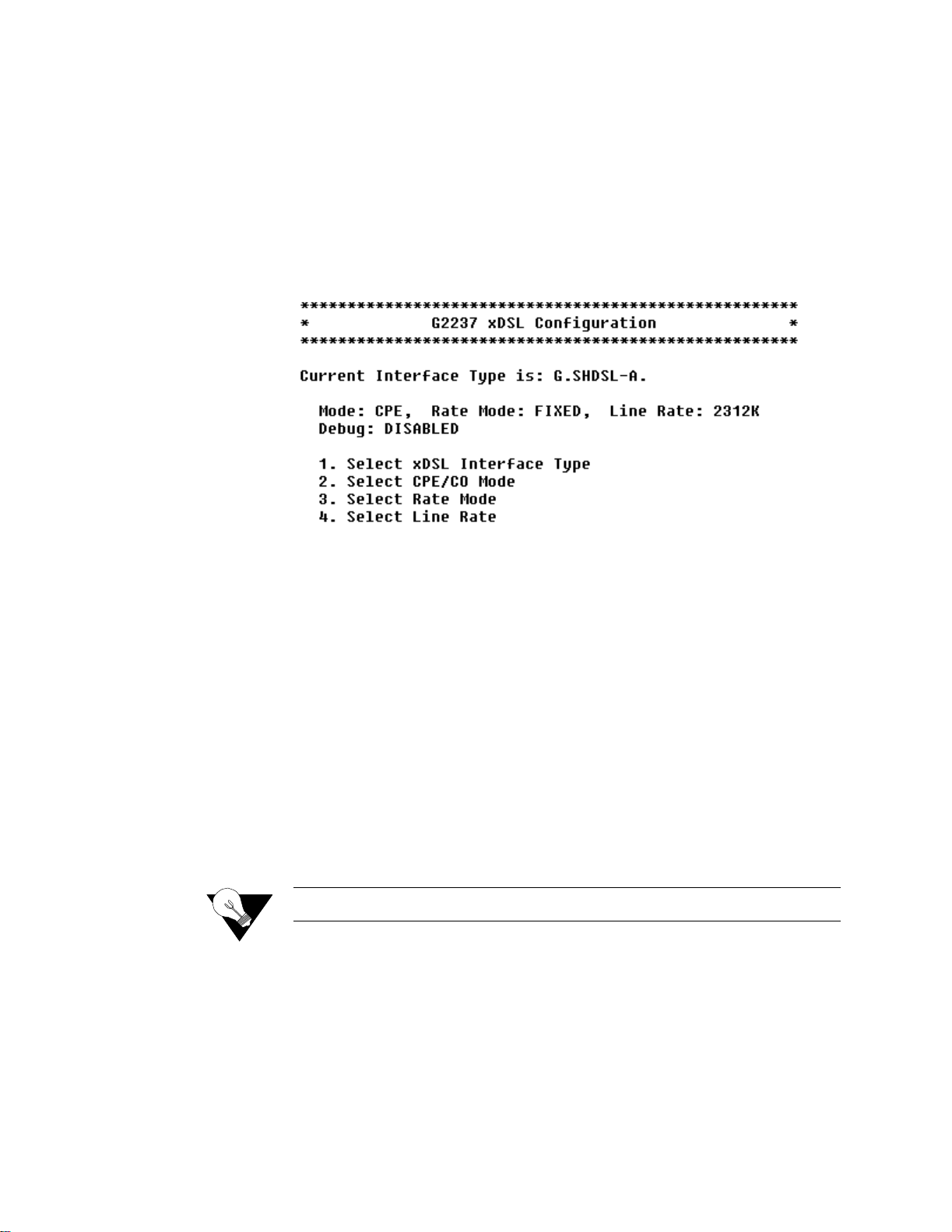
Configure Physical Interface − SHDSL
The tasks described in this section all begin on the SHDSL Configuration
menu (Figure 4.6). You should review and update each of these options as
necessary, and always reset the IAD when you finish SHDSL configuration.
To configure the SHDSL interface, Type “2” (Configure P hysical In terface)
on the WAN Configuration menu (Figure 4.2) to display the SHDSL
Configuration menu.
Select SHDSL
Interface Type
Figure 4.6
To select the Interfa ce Type, follow the steps below.
SHDSL Configuration Menu
1 Type “1” on the SHDSL Configuration menu (Figure 4.6). The IAD
displays the cur rent SHDSL Interface Type menu. Type the option to select
SHDSL Annex A for operation in the U.S. or Annex B for operation in
Europe. The IAD sets the interface type and displays the menu
2 Press Escape to return to the SHDSL Configuration menu.
Select CPE or CO
Mode
To select CPE or CO Mode, follow the steps below.
1 Type “2” on the SHDSL Configuration menu (Figure 4.6). The IAD
displays the current SHDSL Mode and prompts you to change it.
2 Type “1” to select CO, or type “2” to select CPE. The IAD sets the mode
and redisplays the SHDSL Configuration menu.
NOTICE: The CO Mode is reserved for testing. CPE is the normal mode.
Enable/Disable
Adaptive Rate Mode
To configure the Adaptive Rate Mode, follow the steps below.
1 Type “3” on the SHDSL Configuration menu (Figure 4.6) to display the
Configure SHDSL Rate Mode menu.
2 Type “1” to select Fixed, or type “2” to select Adaptive. The IAD sets the
rate mode and displays the menu.
3 Press Escape to return to the SHDSL Configuration menu.
4-6 7000 Series (7200p/7500p)

Select Line Rate
To select a Line Rate, follow the steps below.
1 Type “4” on the SHDSL Configuration menu (Figure 4.6) to display the
current line rate and a prompt to change it.
2 Type a line rate value (between 64 and 2320 kbps). This value must be
divisible by 8. The IAD sets the rat e and display s the SHDSL Configur ation
menu.
Configure Physical Interface − T1/E1
The tasks described in this section all begin on the T1 or E1 Configuration
menu. The tasks are described in order. Review and update each of the
options as necessary, and reset the IAD when you finish WAN configuration.
Type “2” on the WAN Configuration menu (Figure 4.4) to display the T1
Configuration menu (Figure 4.7).
Figure 4.7
The top part of the menu displays the current configuration. You can change
the configuration by selecting the appropriate option in accordance with the
details provided below for each option. Remember always to reset the IAD
when you finish T1 configuration.
T1 Configura tion Menu
Select Frame Mode (D4
or ESF)
To select t he Frame Mode , follow th e steps b elow.
1 Type “1” on the T1 Configuration menu (Figure 4. 7) to select F rame Mode
(D4 or ESF) and display the T1 Frame Mode menu:
Configuration 4-7

Figure 4.8
Select T1 Frame Mode Menu
2 Type “1” to select ESF Frame Mode, or “2” to select D4 Frame mode.
The IAD resets the interface and redisplays the T1 Frame Mode menu.
3 Press Escape to return to the T1 Configuration menu.
4 Continue with other configuration tasks.
Select Transmit Line
Build Out
To select Line Build Out, follow the steps below.
1 Type “2” on the T1 Configuration menu (Figure 4.7) to display the Line
Build Out menu.
Figure 4.9
Select Line Build Out Menu
2 Type the option to select the line build out that corresponds to the T1 span
length in use. The IAD resets the interface and redisplays the Select Line
Build Out menu.
3 Press Escape to return to the T1 Configuration menu and continue with
other configurat ion tasks.
Select B8ZS or AMI
To select B8ZS or AMI, follow the steps below.
1 To set zero suppression, type “4” on the T1 Configuration menu ( Figure
4.7) to select B8ZS or AMI. The IAD displays the current setting and
prompts you to change it.
2 Type “Y” to change the setting.
3 Press Escape to return to the T1 Configuration menu and continue with
other configurat ion tasks.
4-8 7000 Series (7200p/7500p)

Configure Loopback
To configure loopback, follow the steps below.
1 Type “5” on the T1 Configuration menu (Figure 4.7) to configure
loopback. The IAD displays the current setting for each type of loopback
and ESP loopback commands, and the Loopback Configuration menu
(Figure 4.10).
Figure 4.10
Loopback Configuration Menu
2 Type the option number “1”, “2” or “3” to enable or disable Outward
Payload, Outward Line, and Inward Line Loopback. Inward Loopback is
valid only when the IAD is in Maste r Mode. The IAD makes the change a nd
resets the interfa ce.
3 Type “4” to enable or disable receipt of ESF loopback commands. (This
option is valid only when Framing Mode is set to ESF). The IAD saves the
changes and redisplays the Select Loopback Configuration menu.
Configure Transmit
and Receive Channels
4 Press Escape to return to the T1 Configuration menu and continue with
other configurat ion tasks.
To configure Transmit and Receive Channels, follow the steps below.
1 Type “6” on the T1 Configuration menu (Figure 4.7) to select Configure
Transmit Channels, or “7” to select Configure Receive Channels. The
IAD displays a message indicating the number of channels enabled, and
displays the Channel Configur ation menu (Figure 4.11).
Figure 4.11
Each option on this menu is described in detail below.
Channel Configuration Menu
Configuration 4-9

Enable or Disable All Channels
Type “1” to enable all channel s, or type “2” to disable all channels. The
IAD makes the change and resets the interface. (The menu and reset messages
may conflict; press any key to refresh the menu.)
Select Individual Channels
1 Type “3” to enable or disable speci fic ch an nel s . If all chann e ls are
disabled, this option enables specific channels. Conversely, if all channels
are enabled, this option disables specific channels .The IAD displays
prompts you to select Channel Enable /Disable.
2 For each channel, type the number an d press Enter. When you have ente red
all channels to enable or disable, press Enter. The IAD saves the
configuration and displays the T1 Configuration menu.
3 Continue with other configuration tasks.
Select Channel Range
To select Channel Range, perform the following steps:
1 Type “4” to enable a range of channe ls. The IAD displays the channel
status and prompts you to select a Channel Range and to type in the
Beginning Channel.
Configure Transmit
Clock Source
2 Type the beginning channel and press Enter. The IAD prompts you to type
in the Last Channel of Range.
3 Type the ending channel to enable and press Enter. The IAD makes the
change and saves the configuration and displays the T1 Configuration
menu.
4 Continue with other configuration tasks.
To Configure the Transmit Clock Source, follow the steps below.
1 Type “8” on the T1 Configuration menu to select Configure Transmit
Clock Source, which will display the Select Tx Clock Source menu (Figure
4.12) with a status message.
Figure 4.12
Select Tx Clock Source Menu
2 Type “1” to select External or Slave mode, or type “2” to sele c t In t e rnal
or Master mode. The IAD saves the configuration a nd resets the interface.
4-10 7000 Series (7200p/7500p)

3 Press Escape to return to the T1 Configuration menu and continue with
other configurat ion tasks.
4 After you reset the IAD, you will see a prompt to type “1” to sel ect
External or “2” to select Internal mode. Enter your selection.
The IAD saves the configur ation an d resets the interfac e.
Change to E1 Mode
Type “9” on the T1 Configuration menu (Figure 4.7) to switch from T1 to
E1 mode (Figure 4.13).
Select Frame/CRC4
Mode
Figure 4.13
E1 Configurat ion Menu
Type “1” on the E1 Configuration menu to display the E1 Frame Mode
menu (Figure 4.14). From this menu, you may select the framing for the
network side of the DSU/CSU (default is FAS).
Figure 4.14
E1 Frame Mode Menu
Select Line Build Out
1 Type “3” on the E1 Configuration menu to display the E1 Line Build Out
menu (Figure 4.15).
Configuration 4-11

Figure 4.15
E1Line Build Out Menu
2 Type the option to select th e Line Build Out that corresponds to the E1 span
length in use. The IAD resets the interface and redisplays the Select Line
Build Out menu.
3 Press Escape to return to the E1 Configuration menu and continue with
other configurat ion tasks.
Configure S-Bits
Configure Clock
Source
Type “4” on the E1 Configuration menu to display the Configure S-Bits
menu (Figure 4.16). Toggle to display the status of special bits found in
timeslot zer o.
Figure 4.16
Configure S-Bits Menu
To Configure the Clock Source, follow the steps below.
1 Type “7” on the E1 Configuration menu to select Configure Clock Sourc e,
which will display the Select Tx Clock Sourc e menu (Figure 4.17) with a
status message.
4-12 7000 Series (7200p/7500p)

Figure 4.17
Select Tx Clock Source Menu
2 Type “1” to select External or Slave mode, or type “2” to sele c t In t e rnal
or Master mode. The IAD saves the configuration a nd resets the interface.
3 Press Escape to return to the E1 Configuration menu and continue with
other configurat ion tasks.
4 After you reset the IAD, you will see a prompt to type “1” to sel ect
External or “2” to select Internal mode. Enter your selection.
Displaying Physical
Layer Stats and Alarm
Log
The physical layer statistics displays the T1/E1 error rate in errors per second
for the past second. An event log (up to 5 kB) is maintained for certain
events. The time stamp is relative to the last system reset. As new events are
added, older events are discarded when the file size is maximized.
Events include the start and end of Telnet sessions, SNMP access with an
invalid community name, system reset and system reset from menu command,
and the WAN link going up or down.
1 Type “P” on the T1/E1 Configuration menu (Figure 4.7) to display the
physical layer statistics and the alarm log.
Figure 4.18
Sample Physical Layer Stats and Alarm Log:
2 Enter any key to continue paging through the report; pres s Escape to cancel
and return to the T1/E1 Configuration menu.
Configuration 4-13

Clear Physical Layer
Stats
Type “Z” on the T1/E1 Configuration menu (Figure 4.7) to clear all Physical
Layer statistics.
Configure Physical Interface − USI
The tasks described below begi n on the USI Configuration menu (Figure 4.19).
Review and update these options as necessa ry and always reset the IAD when
you have completed USI Interface configuration.
Figure 4.19
USI Configuration Menu
1 Type “1” on the USI Configura tion menu to see the menu bel ow and select
the physical layer protoc ol for the USI port. Select either RS-530 or V.35
for the physical interf ace.
Figure 4.20
USI Interface Type
2 Type “2” on the USI Configuration menu to select the USI data rate and
clocking opti ons. The data r ate is in 64 kbps incr ements up to a m aximum of
2.048 Mbps. The Receive Clock can be configur ed to use eit her an internal
or external clock source.
Figure 4.21
Serial Interface Clock Speed Option Menu
To set the speed manually, enter the desired multiplier of 64 kbps (maximum
is 32 or 2.048 Mbps).
4-14 7000 Series (7200p/7500p)

Configure Datalink Protocol
If you are setting up voice and data channels, you can select ATM or Frame
Relay as you set up the channels as described below.
To select ATM or Frame Relay as the datalink protocol, on the WAN
Configuration menu, type “1”. The IAD displays the WAN Datalink Protocol
Configuration menu (Figure 4.22), identifying the current datalink protocol
just below the banner.
Figure 4.22
WAN Datalink Protocol Configuration Menu
NOTICE: The WAN Datalink Protocol Configuration menu sets up the IAD
internet link for Level 2 Transmission Convergence onto the physical
link. The following generic description of the options listed on this
menu are for information only. Specific encapsulation options are
shown and selected when configuring ATM PVCs (refer to page 4-16)
or Frame Relay DLCIs (refer to page 4-23).
ATM or Frame Relay
Multiprotocol over ATM (RFC 1483) encapsulation or Multiprotocol over
Frame Relay (RFC 1490) encapsulation.
When you select ATM as the datalink protocol, the IAD displays the PVC
and ATM options on the WAN Configuration menu. These options are 3 and
4 as shown in Figure 4.3 above.
When you select Frame Relay, the IAD displays the Frame Relay options on
the WAN Configuration menu − options 3 and 4 on the menu shown below
(although the example below is the 7200p menu, the 7500p Frame Relay
options are also 3 and 4).
NOTICE: The USI interface does not support ATM.
TDM Voice (7200p Only)
This option lets you configure, on a per-DS0 basis, voice traffic for the POTS
ports and data traffic for the Ethernet port.
Configuration 4-15

Configure ATM PVCs
You may configure up to eight ATM PVCs on the IAD. Remember always to
reset the IAD to make PVCs active.
1 Type “3” on the WAN configuration menu (Figure 4.4). The IAD displays
the ATM PVC Configuration menu (Figure 4.23)
NOTICE: Before you configure PVCs, you must first set the datalink protocol
ATM. If option 3 on the WAN Configuration menu displays Configure
DLCIs instead of Configure PVCs, your datalink protocol is set to
Frame Relay instead of ATM.
Figure 4.23
ATM PVC Configurat ion Menu
2 Type the option to perform a task. Each option is described below.
Add New PVC
To add a new PVC, follow the steps below.
1 On the ATM PVC Configuration menu, type “1”. The IAD prom pts you to
enter the VPI.
2 Type a VPI value between 0 and 255 (default 0) and press Enter. The IAD
then prompts you for the VCI.
3 Type a VCI value between 32 and 65535 and press Enter. The IAD displays
the ATM Encapsulation Configur ation menu as shown in Figure 4.24.
4-16 7000 Series (7200p/7500p)

Figure 4.24
ATM Encapsulation Configuration Menu
4 Type the option for the encapsulation to configure for this PVC. If you
select RFC 2364 (PPPoATM with LLC Encapsulation) or RFC 2364
(PPPoATM using VC Muxing), follow the on-screen messages to set the
PPP authorization type. The IAD displays the ATM Service Category
Configuration menu (Figu re 4.25) .
Figure 4.25
ATM Service Cate gory Configuration Menu
5 Type “1” to select CBR for high priority data
− or −
Type “2” to select UBR for low priority data. The IAD displays the ATM
Peak Cell Rate (PCR) Configuration menu (Figure 4.26).
Figure 4.26
ATM Peak Cell Rate (PCR ) Configuration Menu
6 Type the value for the Peak Cell Rate. The IAD saves the configuration and
displays the PVC Configurati on menu where you may continue with other
PVC management tasks.
Configuration 4-17

NOTICE: Do not use “0” for Voice PVC because “0” will use all available
bandwidth, including CBR bandwidth that is not being used. Do not
oversubscribe available PCR. Use “0” for only one (1) PVC. Refer to
Peak Cell Rate (PCR) Considerations and Recommendations on
page C-2.
Modify Existing PVC
1 Type “2” on the ATM PVC Configuration menu (Figure 4.23) . The IAD
displays the following por t table, and prompts you to select the appropriate
port.
AAL5 o r AAL0
2 Type the port number and press Enter.The IAD prompts you to enter the
VPI:
3 Type a VPI value between 0 and 255 (default 0) and press Enter. The IAD
then prompts you to enter the VCI:
4 Type a VCI value between 32 and 65535 (the default is 38 for data and 39
for voice) and press Enter. The IAD displa ys the ATM Encapsulation
Configuration menu (Figure 4.24).
Select the encapsulation you want to assign to this PVC in accordance with
the following paragraphs.
1 Type “1” on the ATM Encapsulation Configuration menu (Figure 4.24) to
select AAL5, or “2” to select AAL0 encapsulation. The IAD displays the
ATM Service Category Configurat ion menu (Figure 4.25).
2 Type “1” to select CBR for high priority data
− or −
Type “2” to select UBR for low priority data. The IAD displays the Peak
Cell Rate Configuration menu (Figure 4.26).
3 Type the PCR value or press Enter to set the PCR to the maximum rate for
the current line speed. The IAD saves the configuration and displays the
ATM PVC Configuration menu.
4-18 7000 Series (7200p/7500p)

Proprietary Voice
Encapsulation
Type “3”on the ATM Encapsulation Configuration (Figure 4.24) menu to
select Proprietary Voice encapsulation over a specific PVC. The IAD saves
the configuration and displays the ATM PVC Configuration menu.
NOTICE: Proprietary Voice Encapsulation is used for Copper Com and Jetstream
voice PVCs only.
RFC 1483 (VC
Muxing) or RFC 1483
(LLC Encapsulation)
RFC 236 4 (PPPoATM
with LLC
Encapsulation) or RFC
2364 (PPPoATM using
VC Muxing)
1 Type “4” on the ATM Encapsulation Configuration (Figure 4.24) menu to
select RFC 1483 encapsulation with VC Muxing or type “5” to selec t RF C
1483 with LL C encap s ul ati on. The IA D dis p lay s the A T M Ser v ice
Category Configurat ion menu (Figure 4.25).
2 Type “1” to select CBR
− or −
Type “2” to select UBR. The IAD displays the Peak Cell Rate
Configuration menu (Figu re 4.26) .
3 Type the PCR value or press Enter to set the PCR to the maximum rate for
the current line speed. The IAD saves the configuration and displays the
ATM PVC Configuration menu (Figure 4.23).
Options 4 and 5 on the ATM Encapsulation Configuration menu (RFC 1483
using VC Muxing) support routing and bridging.
1 Type “6” on the ATM Encapsulation Configuration menu (Figure 4.24) to
select RFC 2364 (PPP0ATM with LLC encaps ulation) or t ype “7” to select
RFC 2364 (PPP0ATM with VC Muxing).
Figure 4.27
PPP Authorization Menu
2 The IAD displays the current PPP author ization and prompts you to chan ge
it. If you select options 1 through 4, the IAD displays the current PPP
authorizatio n user ID and prompts you to enter a new PPP user ID.
3 Enter the new user ID and press Enter and then type a password and press
Enter. If you select option 0 (None), the IAD displays the IPCP IP Address
Type menu.
Configuration 4-19

Figure 4.28
IPCP Configuration Menu
4 Type the option corresponding to the IP address you want to use. The IAD
displays the status of the DNS server assignment for the selected port, and
prompts you to enable or disable it:
5 Type “E” to enable, or “D” to disable the DNS server assignment for T1/
E1 on this port. The IAD reports the change, displays the stat us of the DNS
server assignment for the port, and prompts you to enable or disable it:
6 Type “E” to enable, or “D” to disa bl e the IP mask a ssignment f or T1/ E1 on
this port. The IAD transfers the IP address and mask assigned to a WAN
port to a LAN port and then displays the ATM Service Category
Configuration menu (Figu re 4.25) .
7 Type “1” to select CBR for high priority data
− or −
Type “2” to select UBR for low priority data. The IAD displays the Peak
Cell Rate Configuration menu (Figure 4.26).
AAL2/LES
8 Type the PCR value or press Enter to set the PCR to the maximum rate for
the current line speed. The IAD saves the configuration and displays the
ATM PVC Configuration menu.
Type “9” on the ATM Encapsulation Configuration menu (Figure 4.24) to
display the AAL2 Audio Profile Format menu.
1 To select ITU, type “1”. The IAD displa ys the AAL2 Audio Profile menu
with available optio ns. Type “2” for ATM Forum.
The IAD displays the Peak Cell Rate (PCR) Configuration menu (Figure
4.26).
2 Type the PCR value or press Enter to set the PCR to the maximum rate for
the current line speed. The IAD saves the configuration and displays the
ATM PVC Configuration menu.
3 Type “A” for RFC 2516 (PPoE with LLC) or “B” for RFC 2516 (PPoE
with VC mux.
NOTICE: AAL2/LES encapsulation is used for AAL2/LES-CAS and AAL2/LES
ELCP voice applications.
Delete PVC
To delete a PVC, follow the steps below.
4-20 7000 Series (7200p/7500p)

1 Type “3” on the ATM PVC Configuration menu (Figure 4.23) to select
Delete PVC. The IAD displays the port list and a prompt.
2 Type the port number to delete and press Enter.
3 To delete the PVC, type “Y”, or cancel the deletion by typing any other
character. The IAD saves the configuration and displays the PVC
Configuration menu where you may continue with other PVC management
tasks.
Show Curren t PVCs
1
To display a list of current PVCs, type “4” on the ATM PVC
Configuration menu (Figu re 4.23) to display the port table with associate d
PVCs:
2 When you have finished viewing the list, press any key to return to the
ATM PVC Configuration menu.
Configure ATM Options
To configure ATM options, type “4” on the WAN Configuration menu
(ATM) to display the ATM Configuration menu (Figure 4.29). Current
datalink protocol on the WAN Configuration menu must be set to ATM to see
the ATM Configuration menu. Remember always to reset the IAD when you
finish ATM configuration. (You may wait to reset until all changes have been
made.)
Figure 4.29
Each of the options on this menu is described in detail below.
ATM Configurat ion Me nu
Configure Payload Scrambling
You must enable payload scrambling (which is disabled by default) for the
IAD to connect to a DSLAM that uses payload scrambling. To enable or
disable payload scrambling, follow the steps below:
1 On the ATM Configuration menu, type “1” to see a prompt that lets you
enable or disable Payload Scr ambling.
2 To enable payload scrambling type “E”, or type “D” to disable. The IAD
saves the configuration and displays the ATM Configuration menu where
you may continue with other ATM tasks.
Configuration 4-21

Configure F4 OAM VPI
One F4 OAM VPI may be configured at a time. When you are configuring an
F4 OAM VPI, if one is not configured, the IAD displays the message, “F4
OAM not configured”; otherwise the current configuration is displayed.
To configure the F4 OAM VPI, follow the steps below.
1 On the ATM Configuration menu (Figure 4.29), type “2” to select
Configure F4 OAM VPI. This value must match one of the WAN PVCs.
For more information, refer to Show Current PVCs on page 4-21. The IAD
displays the status and promp ts you to enter a VPI.
2 Type the VPI on which to configure F4 OAM. The IAD saves the
configuration and displays the ATM Configuration menu where you may
continue with other ATM tasks.
Configure F4 OAM Type
To configure the F4 OAM Type, follow the steps below.
1 On the ATM Configuration menu (Figure 4.29), type “3” to select
Configure F4 OAM Type. The IAD displays the menu shown in Figure
4.30.
Figure 4.30
F4 OAM Type Configuration Menu
2 Type “0” to set F4 OAM to none, or t ype “4” to set for End to End OAM.
The IAD saves the configuration a nd displays the ATM Configurati on menu
where you may continue with other ATM tasks.
Display F4 OAM Configuration
To display the F4 OAM Type currently set, type “4” on the ATM
Configuration menu (Figure 4.29). The IAD displays the status message, and
then displays the ATM Configuration menu.
Send OAM Loopback
1 Type “5” on the ATM Configuration menu (Figure 4.29) to select Send
OAM Loopback. The IAD displays a list of all configured F4 OAM ports
and VPI values.
2 Type the port on which to send the OAM Loopback and press Enter. The
IAD performs a loopback test on the selected port and reports the results,
whether successful or unsuccessful.
3 Press any key to display the ATM Configuration menu.
Configure EmptyCells
4-22 7000 Series (7200p/7500p)
To configure Empty Cells, follow the steps below.

1 Type “6” on the ATM Configuration menu (Figure 4.29), to select
Configure EmptyCells. The IAD displays the current status (“Idle” or
“Unassigned”) and prompts you to change it.
2 Type “1” to select Idle cells , or type “2” to select Unassigned cells.
NOTICE: Empty cell IAD settings must match far-end settings.
Configure DLCIs
Type “3” on the WAN Configuration menu to display the Frame Relay
DLCI Configuration menu. Remember always to reset the IAD after you
finish DLCI configuration.
NOTICE: Before you configure DLCIs, you must first set the datalink protocol to
Frame Relay. If option 3 on the WAN Configuration menu displays
“Configure PVCs” instead of “Configure DLCIs,” your datalink
protocol is set to ATM instead of Frame Relay.
Add New DLCI
Figure 4.31
Frame Relay DLCI Configuration Menu
Each option on the menu is described below.
To add a new DLCI, follow the steps below.
1 On the Frame Relay DLCI Configuration menu, type “1” to select Add
New DLCI. The IAD prompts you to enter a new DLCI number.
2 Type a DLCI value between 16 and 1023 and press Ente r. The IAD di splays
the Fame Relay Encapsulation Configuration menu (Figure 4.32).
Figure 4.32
Frame Relay Encapsulation Configuration Menu
Configuration 4-23

3 Type the option corresponding to the encapsulation method you intend to
use. The IAD displays the Frame Relay DLCI Options menu (Figure 4.33).
Configure Transmit
CIR
Figure 4.33
Frame Relay DLCI Options Menu
NOTICE: To continue without configuring CIR or FRF.12 Fragmentation, press
Escape. CIR is not required for full bandwidth circuits.
To config ure Trans mit CIR , follow t he steps b elow.
1 Type “1” on the Frame Relay DLCI Options menu to select Configure
Transmit CIR. The IAD prompts you to enter the Committed Burst Size
(Bc).
2 Type the Bc in number of bits. The IAD prompts you to enter the Circuit
Throughput.
3 Type the Circuit Throughput and pr ess Ente r. Th e IAD prompts y ou to enter
the Excess Burst Size (Be).
Configure Receive CIR
Configure FRF.12
Fragmentation
4 Type the excess burst value in number of bits and press Enter. The IAD
displays the Frame Relay DLCI Options menu (Fig ure 4.33).
5 Press Escape to return to the Frame Rel ay DLCI Config menu and cont inue,
or proceed to the next section.
To configure Receive CIR, follow the steps below.
1 Type “2” on the Frame Relay DLCI Options (Figure 4.33 ) menu to select
Configure Receive CIR. The IAD prompts you to enter the Bc.
2 Type the Bc in number of bits. The IAD prompts you to enter the Circuit
Throughput.
3 Type the Circuit Throughput in bits per second and press Enter. The IAD
prompts you to enter the Be.
4 Type the Be value in number of bits and press Enter. The IAD displays the
FR DLCI Options menu.
5 Press Escape to return to the Frame Relay DLCI Configuration menu and
continue.
To configure FRF.12 Fragmentation, follow the steps below.
1 Type “3” on the Frame Relay DLCI Options menu (Figure 4. 33) to display
the End-to-End Fragmentation menu (Figure 4.34).
4-24 7000 Series (7200p/7500p)

Figure 4.34
End-to-End Fragmentation Configuration Menu
2 Type “1” to select End-to-End FRF.12, or type “2” to manually set the
fragment size. If yo u type “1”, the IAD displa ys the status and prompts you
to enable or disable End-to-End FRF.12. If you type “2”, the IAD prompts
you to enter the maximum fragment size.
3 Type the fragment size in bytes and press Enter. The IAD displays the End-
to-End Fragmentation Configuration menu. Press Escape to return to the
DLCI Configuration menu.
Modify Existing DLCI
Delete DLCI
To modify an Existing DLCI, follow the steps below.
1 On the Frame Relay DLCI Configuration menu, type “2” to select Modify
Existing DLCI.The IAD displays the port table and prompts you to select
the appropriate port as sho wn in
Figure 4.35
Modify Exist ing DL CI Men u
2 Type the port number corresponding to the DLCI you want to update and
press Enter.
3 Type the new DLCI number and press Enter. The IAD displays the Frame
Relay Encapsulation Configuration menu as shown in Figure 4.32.
4 Continue with the steps listed above under “Adding a new DLCI.”
To delete a DLCI, follow the steps below.
1 On the Frame Relay DLCI Configuration menu, type “3” to select Delete
DLCI. The IAD displays the port table and prompts you to select a port.
Show Current DLCIs
2 Type the port number corresponding to the DLCI you want to delete. To
permanently remove the DLCI config uration, type “Y”. To cancel the
operation, type “N”.
To display all currently configured DLCIs, follow the steps below.
1 Type “4” o n the Fra me Relay DLCI Conf iguration menu t o dis play th e por t
table.
2 Press any key to display the Frame Relay DLCI Configuration menu.
Configuration 4-25

Configure Frame Relay Options
To configure Frame Relay options, type “4” on the WAN Configuration
menu. The IAD displays the Frame Relay menu (Figure 4.36).
Figure 4.36
Frame Relay Options Configurati on Menu
Each of the menu options is described in detail below.
Configure Fragment ation
1 On the Frame Relay Options menu, type “1” to display the Frame Relay
Fragmentation Configuration menu (Figure 4.37).
Figure 4.37
Frame Relay Fragmentation Configur ation Menu
Frame R elay FRF.12
Configuration
2 Type “1” to select Configure FRF.12 Fra gmentation and proceed to
FRF.12 configuration.
− or −
Type “2” to select Copper Mountain Fragmentation and proce ed to
CopperMountain Fragmentation configuration.
Each of these configurations is described below.
Select FRF.12 Fragmentation to display the FRF.12 Configuration menu
(Figure 4.38).
Figure 4.38
Each option on this menu is described in detail below.
Enable/Disable FRF.12
To enable or disable FRF.12, follow the steps below.
FRF.12 Configuration Menu
4-26 7000 Series (7200p/7500p)

1 Type “1” on the Frame Relay FRF.12 Configuration menu. The IAD
displays FRF.12 Fragmentation status (enabled or disabled), and prompts
you to change it.
2 Type “E” to enable End-to-End fragmentation, or type “D” to disable it.
The IAD saves the configuration and displays the FRF.12 Configuration
menu. Press Escape to continue.
Enable A utomatic Fragm ent Sizin g
Type “2” on the Frame Relay FRF.12 Configuration menu to enable
automatic fragment sizing. The IAD saves the configuration and displays the
FR FRF.12 Configuration menu. Press Escape to continue.
Set Manual Fragment Size
To manually set the Fragment Size, follow the steps below.
1 Type “3” on the Frame Relay FRF.12 Configuration menu to manually set
fragment siz ing. The IAD prompts you to ent er the maximum fragment size.
2 Type the maximum fragment size in milliseconds or bytes and press Enter.
The IAD saves the configur ation and displ ays the FR FRF.12 Configur ation
menu. Press Escape to continue.
Configure
CopperMountain
Fragmentation
Configuration
Select Configure CopperMountain Fragmentation by typing “2” on the FR
Fragmentation Configuration menu to display the CopperMountain FR
FRF.12 Configuration menu (Figure 4.39).
NOTICE: With CMCP enabled, the DSLAM controls fragmentation settings, and
IAD configuration is not required.
Figure 4.39
Each option on this menu is described in detail below.
Enable/Disable Copper Mountain Fragmentation
Copper Mountai n FR F.12 Configuration Menu Proprietary for
CopperMount ain DSL AM s
1 Type “1” to display a prompt that lets you enable or disable
CopperMountain fragment ation.
2 Type “E” to enable CopperMoun tain fragmenta tion or ty pe “D” to disa ble .
The IAD saves the configur ation and displ ays the FR FRF.12 Configur ation
menu. Press Escape to continue.
Configuration 4-27

Set Real-Time DLCI
1 Type “2” to set up the IAD for real-time DLCI. The IAD displays the port
table and prompts you to select a port.
2 Type the port number corresponding to the DLCI you want to set to real-
time. The IAD saves the configuration and displays the FR FRF.12
Configuration menu. Press Escape to continue.
Configure Management Protocol
To configure Management Protocol, follow the steps below.
1 Type “2” on the Frame Relay Options menu to display the Confi gure
Management Protocol menu (Figur e 4.4 0).
Figure 4.40
Frame Relay Manageme n t Protocol Menu
2 Type the number that c orresponds to the protoc ol on you r network a nd pre ss
Enter.
Configure Congestion Par ame te rs
To configure Congestion Parameters, follow the steps below.
1 Type “3” on the Frame Relay Options menu to display the Fame Relay
Congestion Configura tion menu (Figure 4.41).
Figure 4.41
Frame Relay Conges tion Configurat ion Menu
2 Select Configure Transmit Congestion Para meters and then follow the on-
screen messages to
• FECN/BECN condition set size
• FECN/BECN condition clea r size
4-28 7000 Series (7200p/7500p)

• FECN/BECN max number of bytes to store
− or −
Select Configure Receive Congestion Parameters and then follow the on-
screen messages to
• FECN/BECN condition set size
• FECN/BECN condition clea r size
• FECN/BECN max number of bytes to store
4 Reset the IAD for changes to take effect.
Enable/Disable CopperMountain CMCP
NOTICE: When using a CopperMountain DSLAM, CMCP allows the DSLAM to
configure many IAD parameters automatically. IAD parameters
controlled by CMCP include fragmentation and voice gateway support.
For more information, refer the CopperMountain DSLAM guide.
1 Type “4” on the Frame Rela y Options m enu. The I AD displays t he CMCP
status and prompts you to change it.
2 Type “E” to enable CopperMountain CMCP or “D” to disable.
Router Configuration
This section describes how to configure the IAD as a router. You may
configure the IAD as a router or a bridge, depending on your application.
Optionally, you may also configure some ports for routing and some ports for
bridging. For example, you might use a bridge connection for Internet traffic
and use a separate routed port for remote management. Alternatively, you can
configure the bridge port on the WAN side with IPoBridge to use the bridged
connection for remote management. Refer to Basic Bridge Setup Tasks on
page 4-43.
A router is a network layer device that uses one or more metrics to determine
the optimal path along which network traffic should be forwarded. Routers
forward packets from one network to another based on network layer
information.
A router generally improves overall efficiency for a complex network, but a
bridge provides better speed and flexibility for the overall network.
Basic Router Setup Tasks
To configure the IAD as a router, complete the following tasks:
• Configure IP addresses on the LAN and WAN ports (page 4-31)
• Enable RIP poisone d reverse (recommended) (page 4-35), add a static route
(page 4-33), or add a default route (page 4-34)
Configuration 4-29

• Disable bridging globally (page 4-46) or by port (page 4-46)
• Disable Spanning Tree Protocol (Spanning Tree) globally (page 4-47) or by
port (page 4-48)
Use the flowchart below to plan your tasks, based on your router
configuration requirements.
Figure 4.42
Router Configur ation Task Flowchart
Routing
DHCP Client?
Yes
Enable
RIP
globally
Enable
version by
port
Yes
Static
Using
RIP?
No
Define
Routes
Default
No
Assign
static
IPs
Router Configuration Menu
Router tasks are all displayed and accessed on the Router Configuration menu
(Figure 4.43) displayed by typing “2” on the Main menu (Figure 2.2).
Remember always to reset the IAD (page 2-8) when you have finished router
configuration for your changes to take effect.
4-30 7000 Series (7200p/7500p)

Figure 4.43
Router Configuration Menu
You may sign on as Supervisor or Network Manager to configure the IAD as
a router. Options that display in the Router Configuration menu are the same
for both security levels.
Configure Port IP Address
To configure the IAD as a router, you must assign an IP address to both the
LAN and WAN po rts, each with diffe rent subnet masks.
NOTICE: You can assign up to eight IP addresses on each of the WAN and LAN
ports.
To config ure an IP address, follow t he steps b elow:
1 Type “C” on the Router Configuration menu (Figure 4.43) to select
Configure Port IP address. The IAD displays the available interfaces. Type
the number that corresponds with the interface you want to configure.
(Sample shown below in Figure 4.44.)
Figure 4.44
2 The IAD displays the port table for this interface and prompts for a port.
Availa bl e In terfaces D is pl a y.
Configuration 4-31

3 Type the port to configure and press Enter. The IAD displays the IP
interfaces on the port you’re configuring:
4 Enter the ID of the interface (0-7) to configure and press Enter. The IAD
displays the current IP Address and prompts for a new one.
5 Type the new IP address and press Enter. The IAD displays the current
Subnet Mask and prompts for a new one:
6 Type the new Subnet Mask address and press Enter. The IAD prompts you
to determine traffic priority on this port:
7 Do one of the following:
Set th e inte rf ace to h igh priorit y to type “H”
− or −
Set th e inte rf ace to n orma l p r i o r i ty to typ e “N”
Configuration is complete.
8 The IAD then prompts you to save the new information.
9 Type “Y” to confirm your changes, or press Esc ape to cancel. If you
confirm, the IAD saves the setti ngs. If bridging is enabled and an IP address
is assigned on the WAN interface, the IAD displays an IP Over Bridge
prompt.
10 Type “E” to enable IP Over Bridge on the WAN port, or “D” to disable it.
The IAD saves the changes and displays the Router Configuration menu
(Figure 4.43).
11 Repeat the steps listed above for each remaining port to configure.
12 Continue with other configuration tasks, or press Escap e to retu rn to the
Main menu.
13 Reset the IAD when you finish router configuration.
Unconfigure Port IP Address
To unconfigure a Port IP Address, follow the steps below.
1 Type “U” on the Router Configuration menu (Figure 4.43) to select
Unconfigure Port IP Address. If more than one WAN port is installed or
more than one PVC/DLCI exists, the IAD displays the inte rfaces on this
IAD (sample shown in Figure 4.44).
2 Type the interface number to which the IP address is assigned. The IAD
displays the port table fo r this interface and prompts you to select a port.
3 Type the port and press Enter. The IAD displays the IP interfaces on the
port you’ve selected.
4 Enter the ID of the interface to delete and press Enter. The IAD deletes the
IP address and saves the configuration.
5 Continue with other configuration tasks, or press Escape to return to the
Router Configuration menu.
4-32 7000 Series (7200p/7500p)

Configure Port Maximum Transmission Unit (MTU)
The MTU setting controls IP fragmentation of packets transmitted through the
specified p ort. Pa cket whos e size is greater t han the MTU va lue are
fragmented to fit into the MTU size limit.
To set a maximum transmission unit value for a port, follow the steps below:
1 Type “M” on the Router Configuration menu (Figure 4.43) to select
Configure Port Max Transmission Unit. The IAD displays the port table for
this interface and prompts you to se le ct a port.
2 Type the port number and press Enter. The IAD displays the current
configuration and prompts you to change it.
3 Type the new MTU value ( 100-1500 ) an d press En ter. (When se t at 1500 , IP
fragmentation is dis abled). The IAD saves the changes.
4 Continue with other configuration tasks, or press Escape to return to the
Router Configuration menu.
For furth er informat ion, refer t o Frame Relay Applications Notes on page C-1.
Add/Remove a Static Route
To create, update, and/or delete static and default routes, type “S” on the
Router Configuration menu (Figure 4.43). The IAD displays the Router
Modification menu, which contains commands to manage the IAD’s route
table:
Add a Static Route
Figure 4.45
Each option on this menu is described in detail below.
Router Modification Menu
1 On the Router Modification menu type “A” to select Add a Static Route.
The IAD prompts you to input the destination address:
2 Type the destination address to add and press Enter. The IAD displa ys the
current subnet mask and prompts you to ente r the network mask of the
route.
3 Type the network mask and press Enter. The IAD prompts you for the
gateway address.
4 Type the gateway address, press Enter. The static route is added. The IAD
then asks if you want to save this route in the static configuration.
Configuration 4-33

5 Type “Y” to confirm, or Escape to cancel. If you confirm, the Route Table
is updated and the IAD prompts you to add more routes:
6 Type “Y” to add more routes, or Esc ape to can c el . Repeat these steps for
each route that you want to add.
7 Continue with other configuration tasks, or press Escape to return to the
Router Modification menu.
Remove a Route
Add or Change Default
Route
To delete a static route from the Route Table, follow the steps below:
1 On the Router Modification menu, type “R” to select Remove a Route. The
IAD prompts you to enter the address of the route to remove:
2 Type the IP address of the route to remove and press Enter. The IAD
removes the route from the table and the IAD displ ay s the Router
Modification menu. Repeat these steps for each route that you want to
remove.
3 Continue with other configuration tasks, or press Escape to return to the
Main menu.
To add or change a default route, follow the steps below.
1 On the Router Modification menu, type “F” to select A d d/C h ang e the
Default Route. The IAD prompts you to enter the default gateway address.
(You may type “0” for a list of interfa ces ):
2 Type the default gateway address and proceed to step 3 above or type “0”
to display the port table.
3 Enter the number of the port and pre ss Enter . The def ault route is set and t he
Route Table is will be updated when the IAD is reset.
4 Continue with other configuration tasks, or press Escape to return to the
Router Modification menu.
Remove Default Route
To remove a default route, follow the steps below.
1 On the Router Modification menu type “T” to select Remove the Default
Route. The default route is immediately deleted and the Route Table is
updated when the IAD is reset.
2 Continue with other configuration tasks, or press Escape to return to the
Router Modification menu.
Display Route Table
Type “D” on the Router Modification menu to display the Route Table.
Enable/Disable RIP
When you enable RIP, the IAD sends routing data to adjacent routers and
dynamically learns the associated network topology. To enable RIP globally,
follow the steps below.
1 Type “R” on the Router Configuration menu (Figure 4.43), to select
Enable/Disable RIP. The IAD displays the RIP current status and prompts
you to enable or disable RIP globally.
4-34 7000 Series (7200p/7500p)

2 Type “E” to enable RIP globally, or “D” to disable it globally. The IAD
saves the config urati on and dis plays th e Router Confi guration m enu ( Figure
4.43).
3 Continue with other configuration tasks, or press Escape to return to the
Main menu.
NOTICE: For RIP to function correctly, you must enable RIP globally or locally
(by port) and set the RIP version. The order in which you perform each
procedure is irrelevant.
Configure RIP Version by Port
To configure RIP Version by Port, follow the steps below.
1 Type “V” on the Router Configuration menu (Figure 4.43) to select
Configure RIP Version by Port. If more than one WAN port is installed or
more than one PVC/DLCI exists, the IAD displays the inte rfaces on this
IAD (sample shown in Figure 4.44).
2 Type the interface number to set. The IAD displays the port table fo r this
interface and prompts you to select a port:
3 Type the port number to set and press Enter. The IAD displays the RIP
configuration and status of the slot and port you’re sett ing, and prompts you
to select a new version:
4 Type the option number of the ve rsion to s et. Setti ng the RI P versi on for thi s
port is complete. The IAD saves the setti ngs and displays the Router
Configuration menu (Figure 4.43). Repeat these steps for each remaining
port to set.
5 Continue with other configuration tasks, or press Escape to return to the
Main menu.
Configure RIP Poisoned Reverse by Port
To configure RIP Poisoned Reverse by port, follow the steps below.
1 Type “P” on the Router Configuration menu (Figure 4.43) to select
Configure RIP Poisoned Reverse by Port. The IAD displays the interfaces
on this IAD (sample shown in Figure 4.44)
2 Type the number of the port to enable or disable. The IAD displays the RIP
status of this port and prompts you to enable or disable RIP Poisoned
Reverse for that slot and port.
3 Type “E” to enable RIP Poisoned Reverse, or type “D” to disable it. The
IAD saves the configuration, and displays the Router Configuration menu
(Figure 4.43). Repeat these steps for each port for which you want to enable
RIP poisoned reverse.
4 Continue with other configuration tasks, or press Escape to return to the
Main menu.
Configuration 4-35

Configure DNS Client
DNS Client allows the IAD to use fully qualified domain names (for example,
www.verilink.com). To configure the IAD as a DNS Client, type “N” on the
Router Configuration menu (Figure 4.43). The IAD displays the DNS Client
menu:
Set Primary (or
Secondary) DNS
Server IP Address
Set DNS Server
Timeout
Figure 4.46
Each option on this menu is described in detail below.
To set the Primary (or Secondary) DNS Server IP Address, follow the steps
below.
DNS Client Menu
1 On the DNS Client menu, type “A” to select Set DNS Server IP Address.
The IAD displays the current address and prompts you to enter a new one.
2 Type the new DNS server address and press Enter. The IAD updates the
configuration and displays the DNS Client menu.
3 Continue with other configuration tasks, or press Escape to return to the
Router Modification menu.
To set the DNS Server Timeout, follow the steps below.
1 On the DNS Client menu, type “T” to select Set DNS Server Timeout. The
IAD displays the current value and lets you specify a new value.
2 Type the new timeout value (default 5) and press Enter. The IAD updates
the configuration an d displays the DNS Client menu.
3 Continue with other configuration tasks, or press Escape to return to the
Router Modification menu.
4-36 7000 Series (7200p/7500p)

Display the DNS Cache
and Statistics
To display information about the data in the DNS cache, type “S” on the
DNS Client menu. When DNS Client is enabled, the IAD displays the
information shown below.
Press any key to return to the DNS Client menu when you have finished
reviewing the information.
Configure DHCP Client
1 Type “H” on the Router Configuration menu (Figure 4.43) to select
Configure DHCP Client. If more than one WAN port is installed or more
than one PVC or DLCI exists, the IAD displays the availa ble interfaces
(sample shown in Figure 4.44):
2 Type the interface number to set. The IAD displays the port table fo r this
interface and prompts you for a port number.
3 Type the port to set and press Enter. The IAD displays the status of the
selected slot and port, and prompts you to change it.
4 Type “E” to enable DHCP Client on this port, or “D” to disable it. The
IAD saves the changes and displays the Router Configuration menu (Figure
4.43). Repeat these steps f or each remaining port.
5 Continue with other configuration tasks, or press Escape to return to the
Main menu.
Configure DHCP Relay
DHCP Relay allows the IAD to forward DHCP requests from the LAN to a
separate DHCP Server. To configure the IAD for DHCP Relay, type “L” on
the Router Configuration menu (Figure 4.43). The IAD displays the DHCP
Relay menu (Figure 4.47), which contains commands to configure DHCP
Relay:
Configuration 4-37

Figure 4.47
Each option on this menu is described in detail below.
DHCP Rela y Me n u
Enable/Disable DHCP
Relay
Configure DHCP
Relay
When you enable DHCP Relay, you must provide a DHCP server IP address.
To enable or disable DHCP Relay, follow the steps below:
1 On the DHCP Relay menu, t ype “E” to select Enable/Dis able DHCP Relay.
The IAD displays the current status and prompts you to change it.
2 Type “E” to enable DHCP Relay on this port, or “D” to disable it.
3 The IAD displays the current DHCP server IP address and prompts you to
enter a new addr ess .
4 Type the new DHCP Server IP address. The IAD saves the changes and
displays the Router Configur ation menu (Figure 4.43).
5 Continue with other configuration tasks, or press Escape to return to the
Main menu.
To configure the DHCP Relay, follow the steps below.
1 On the DHCP Relay menu, type “C”. The IAD display s the cu rr en t IP
address and prompts you to enter a new address.
2 Type the new DHCP Server IP address. The IAD saves the changes and
displays the Router Configur ation menu (Figure 4.43).
3 Continue with other configuration tasks, or press Escape to return to the
Router Modification menu.
Display DHCP Relay
Statistics
To display information about DHCP, follow the steps below.
1 Type “S” on the DHCP Relay menu (Figure 4.47). When DHCP Relay is
enabled, the IAD displays a report such as the one below.
2 Press any key to return to the DNS Client menu when you have finished
reviewing the informat ion.
4-38 7000 Series (7200p/7500p)

Configure Telnet Server Port
When using NAT on the IAD, you may want to configure a host behind NAT
as a Telnet Server. In this case, Telnet requests are passed to the host, and not
handled by the IAD. By changing the Telnet port, both the host and IAD may
be accessed via Telnet.
To set the port for the Telnet Server, follow the steps below.
1 On the Router Configuration menu (Figure 4.43), type “T” to select
Configure Telnet Server Port. The IAD displays the current IP address and
prompts you to enter the new Telnet Server port.
2 Type the new Telnet Server port (the default is 23). The IAD saves the
changes and displays the Route r Configuration menu (Figure 4.43).
3 Continue with other configuration tasks, or press Escape to return to the
Main menu.
Configure IP QoS
Type “A” on the Router Configuration menu to select the Configure IP QoS
menu.
Display QoS Settings
Figure 4.48
Type “D” on the IP QoS menu to display the priority of the type of service
(ToS) value. Use this field to create priorities for packets in the IAD. Figure
4.49 shows the default settings.
Figure 4.49
IP QoS Menu
IP QoS Based on ToS Values (Default Settings)
Config QoS
Type “C” on the IP QoS menu to configure the priority level of a service.
The priority level is 1 − 3 and is set in accordance with the ToS value.
Configuration 4-39

Configure IP Filtering
IP Filtering lets you specify rules for handling data packets transitioning an
interface. Based on a set of rules, packets can be passed or blocked when
entering or leav ing an interface.
IP Filtering is one part of creating a Firewall to protect local networks from
undesirab le access.
NOTICE: Please refer to the Applications Notes on IP Filtering found in
Appendix C for the general information and syntax needed to program
the fi lter.
NOTICE: Because each packet must be tested against one or more filters, IP
filtering may significantly affect IAD performance.
To use IP filtering, you must create a text file called filter.st. This file should
be created and edited external to the IAD and then downloaded via TFTP or
XMODEM. The syntax is defined under the Grammar section on page
page C-7. To configure IP Filtering, Type “F” on the Router Configuration
menu (Figure 4.43). The IAD displays the IP Filtering Configuration menu.
read filter.st
print filters
Figure 4.50
IP Filtering Configuration Men u
If the filter.st file is present on the IAD, IP Filtering will be enabled. The IP
Filtering Configuration Menu then lets you load and unload rule sets, print the
current list of filters, and show and clear IP Filter Statistics.
Each option on the above menu is described in detail below.
Type “1” to have the IAD load a new rule set from the filter.st file. Once
you have uploaded the file, the IAD will begin filtering without your having
to reboot the IAD. To upload a file to the file system, refer to File System
Menu on page 3-18.
Type “2” to display a list of currently installed input and output filters
(Figure 4.51).
4-40 7000 Series (7200p/7500p)

Figure 4.51
Display Input/Output Filters Menu
unload all filters
Show IP Filt ering
statistics
Show per filter
statistics
Clear IP filtering
statistics
Temporarily deactivates IP Filtering.
NOTICE: You must unload the old rule set before loading a new rule set.
Displays statistics for IP Filtering. Shows accumulated statistics for all Input
and Output filters
Displays statistics for each active filter rule.
Clears all accumu lated sta tistics.
Configure IP Header Compression (IPHC)
IPHC reduces the number of bytes transmitted across the WAN, thus
conserving bandwidth.
To enable or disable IP header compression, follow the steps below:
1 On the Router Configuration menu (Figure 4.43), type “Q”.
2 The IAD displays the port table and prompts you to enter a port.
3 Type the port number and press Enter. The IAD displays the header
compression status and prompts you to enable or disable IP Header
Compress io n for SH DSL.
4 Type “E” t o e nable I P he ader compre ssion on this port, or “D” to dis abl e it.
If you enable I P header compression , the IAD displays a message similar to
the following:
Springtide Compatibility mode ENABLED (currently not
selectable)
The IAD saves the changes and displays the Router Configuration menu
(Figure 4.43). Continue with other configuration tasks, or press Escape to
return to the Main menu.
Configuration 4-41

Configure LAN IP Broadcast Destination
To set the LAN IP broadcast destination address (where all broadcast IP
packets r eceived on the LAN ports w ill be redi rected), follow the steps be low.
1 On the Router Configuration menu (Figure 4.43), type “B”.
2 The IAD displays the current LAN IP broadcast destination address and
prompts you to enter a new address.
3 Type the new IP address. The IAD saves the changes and displays the
Router Configuration menu (Figur e 4.43).
4 Continue with other configuration tasks, or press Escape to return to the
Main menu.
Display Route Table
To display the Route table and view information about statically configured
routes and dynamically learned ones, type “D” on the Router Configuration
menu (Figure 4.43).
The IAD displays each network address and related information:
Route Table parameters are described in the following table.
Parameter Description
Network Address destination address
Netmask IP subnet mask; number of bits reserve d for the
Gateway Address IP address of packets sent to destination
Interface IP address of outgoing interface
Metric number of hops (routers) required to reach the
Type static | dynamic | RIP | local
Bridge Configuration
This section describes how to configure the IAD as a bridge. A bridge is a
device that connects and passes packets between two network segments that
use the same communications protocol. A router generally improves overall
efficiency for a complex network, but a bridge provides better speed and
flexibility for the overall network.
host ID
specified gateway
4-42 7000 Series (7200p/7500p)

NOTICE: Verilink recommends that bridged network architecture be thoroughly
understood prior to configuring the IAD. Suggested reading:
“Interconnections: Bridges and Routers” by Radia Perlman, AddisonWesley, 1992.
Bridges operate at the data link layer (Layer 2) of the OSI reference model.
In general, a bridge filters, forwards, or floods an incoming frame based on
the MAC address of that frame.
Basic Bridge Setup Tasks
Although the IAD is preconfigured with bridging enabled, you should perform
these tasks for your network:
• Enable bridging globally (page 4-46) or by port (page 4-46)
• Set the bridge aging timer (page 4-47)
• Disable RIP poisone d reverse globally (page 4-35) or by port (page 4-35)
• Enable Spanning Tree globally (page 4-47) or by port (page 4-48)
Use the flowchart below to plan your tasks, based on your requirements.
Configuration 4-43

Figure 4.52
Bridge Configuration Task Flowc hart
Main
Menu
Enable
bridging
globally
Enable
bridging
by port
Enable
spanning tree
globally
Enable
spanning tree
by port
Define
root
bridge
End
Yes
Yes
Using
spanning
tree?
No
Assigning
bridge
priority?
Yes
Define
bridge
priority
Assigning
root
bridge?
No
End
No
Bridge Configuration Menu
Configuring the IAD as a bridge involves several tasks, all of which are
displayed and accessed on the Bridge Configuration menu, displayed by
typing “3” on the Main menu (Figure 2.2).
4-44 7000 Series (7200p/7500p)

Figure 4.53
Bridge Configuration Menu
You may sign on as Supervisor or Network Manager to configure the IAD as
a bridge. Options that display in the Bridge Configuration menu are the same
for both security levels.
NOTICE: Be sure to reset the IAD when you have finished making changes to
Bridge configuration. Resetting the IAD causes the configuration
changes to take effect.
Enabling and Disabling Bridging
For bridging to function correctly, you must enable bridging by port and then
set the bridge aging timer. At least two ports must be enabled for bridging to
function. You must also disable RIP poisoned reverse. The order in which you
perform the procedures is irrelevant.
To enable routing globally, you must disable bridging globally. However, you
may enable routing on some ports and bridging on others, depending on your
requirements.
NOTICE: When bridging is disabled globally or on an interface (port) or an IP
address is unconfigured, IP Over Bridge is disabled automatically.
IP Over Bridging
IP Over Bridging is intended for use when the IAD is in full bridged mode,
and remot e acc ess (T elne t) and /or us er aut hent icatio n (R ADIUS) are r equ ired.
To implement IP Over Bridging, enable bridging globally and by port (as
described in the paragraphs below) on the WAN connection (at least one
DLCI/PVC must be configured), and assign an IP address to the WAN
interface. When these conditions have been met (either in Routing or Bridging
configuration), the IAD will prompt you to enable or disable IP Over
Configuration 4-45

Bridging. When the IP address is unconfigured, IP Over Bridging is disabled
automatically. The IAD will also prompt you to enable or disable IP Over
Bridging when bridging is being enabled on an interface that already has an
IP address assigned.
When an IP address is unconfigured or when bridging is disabled globally or
on an interface (port), IP Over Bridging is disable automatically.
When IP O ver Bri dging is en abled , the IAD e xamines all Ether net packe ts
that have its MAC address as a destination. The ARP packets and IP packets
with a des tination I P addres s that is assigne d to an in terface on the IAD are
processed as IP packets normally are, including ARP resolution. All other
packets are processed in the usual way that a bridge processes them.
When the IAD should send an IP packet out (for example, in response to a
ping, or RADIUS authentication), the ARP resolution is performed in a
manner similar to the way it’s accomplished on Ethernet. If the destination
Mac address is not known, the ARP broadcast request is sent to all interfaces.
The interface tha t receives the reply is used to se nd the actual IP packet.
NOTICE: When using IP Over Bridging with CopperMountain HDIA or
CopperVPN, the default route for the IP interface should be specified
using the IP addre ss of the router, rather than a WAN port number.
Enable/Disable Bridging Globally
To enable or disable bridging globally, follow the steps below.
1 On the Bridge Configuration menu (Figure 4.53), type “G” to display the
status of bridging and a prompt to enable or disable Bridging globally.
2 Type “E” to enable bridging globally, or “D” to disable it globa lly. The
IAD saves the configurati on and displays the Bridge Configuration menu
(Figure 4.53).
3 Continue with other configuration tasks, or press Escape to return to the
Bridge Configuration menu.
Enable/Disable Bridging by Port
To enable or disable bridging by port, follow the steps below:
1 Type “P” on the Bridge Configuration (Figure 4.53) menu to select Enable/
Disable Bridging by Port. The IAD displays the interfaces availabl e on this
IAD as shown in Figure 4.44.
2 Type the number of the interface for which you want to enable bridging.
The IAD displays a port table and prompts you to select the por t.
3 Type the number of the port. The IAD displays the status of br idgi ng on this
interface and port, and prompts you to enable or disable it.
4 Type “E” to enable bridging on this port, or “D” to disable it. The IAD
updates the configuration and displays the Bridge Configur ation menu
(Figure 4.53).
4-46 7000 Series (7200p/7500p)
 Loading...