

Page 1

®
WANsuite
6x30
Reference Manual
January 2002
34-00315.B
i
Page 2

Copyright Notice
Copyright © 2001 Verilink Corporation. All rights reserved. No part of this publication may be
reproduced, transmitted, transcribed, stored in a retrieval system, or translated into any language
in any form by any means without the written permission of Verilink.
Manual Reorder # 34-00315
.B
January 2002
Verilink
®
and WANs uite
®
are r
egistered trademark
s of the
Verilink Corporation.
F
rameStart™
and ServiceAware™ are trademarks of Verilink Corporation.
All other brand and pr oduct nam es used herei n are trademark s or registe red trademarks of their
respective manufacturers.
This document doe s no t c reat e any ex pr ess or imp l ied war ra nt y abou t Verilink or about its prod-
ucts or services. Verilink’s sole warranty is contained in its product warranty. The end-user doc-
umentation is shipped with Verilink’s products and constitutes the sole specifications referred to
in the product warranty. Verilink has made reasonable efforts to verify that the information con-
tained herein is accurate, but Verilink assumes no responsibility for its use or for any infringe-
ment of patents or other rights of third parties that may result. The customer is solely
responsible for verifying the suitability of Verilink’s products for its use. Specifications are sub-
ject to change without notice.
Veri link's product warranty is included at the back of this document.
Documentation Disclaimer
Warranty
ii
WANsuite 6x30
Page 3

WANsuite 6130 FCC
The WANsuite 6130 has been tested and found to comply with the limits for a Class A digital
device, pursuant to Part 15 of FCC Rules . These limits are designed to provide reasona ble pro-
tection against harmful i nterference when the equipment i s operated in a commercial environ -
ment. This equipment generates, uses, and can radiate radio frequency energy and if not
installed and used in accordance with the instruction manual, may cause harmful interference to
radio communications. Operation of this equipment in a residential area is likely to cause harm-
ful interference in which case the user is required to correct the interference at his own expense.
This device must also acc ept any interference received, in cluding interference that may cause
undesired operation.
W ARNING:
W ARNING:
This digital apparatus does not exceed the Class A limits for radio noise emissions from digital
apparatus set out in the Rad i o In ter feren ce Regu lat ions o f t he C an adian D epart ment of Co mmu -
nications.
Le présent appareil numérique n’émet pas de bruits radioélectriques dépassant les limites appli-
cables aux appareils numériques (de la class A) prescrites dans le Règlement sur le brouillage
radioélectrique edi cté par le ministère des Communications du Canada.
When handling this equipmen t, follow t hese basi c safety pr ecautions t o reduce the risk of elec-
tric shock and injury:
•
Follow all warnings and instructions marked on the product and in the manual.
•
Un plug the hardware from the wall outlet before cleaning. Do not use liq uid clean ers or aerosol clean-
ers. U se a slig htly damp cloth for cleaning.
•
Do not place this product on an unstable cart, stand, or table. It may fall, causing serious damage to
the product.
•
Slots in the unit are provided for ventilation to protect it from overheating. These openings must not
be blocked or covered. N ever place this product near a radiator or heat register.
•
This product should be operated only from the type of power source indicated on the marking label
and manual. If you are unsure of the type of power supply you are using, consult your dealer or local
pow er com pany.
•
Do not allow anything to rest on the power cord. Do not locate this product where the cord interferes
with the free movem ent of people.
•
Do not overload wall outlets and ex tensio n cords, as this can result in fire or electric shock.
•
Never push objects of any kind into the unit. They may touch dangerous voltage points or short out
parts that could result in fire or electric shock. Never spill liquid of any kind on this equipm ent.
•
Unplug the equipm ent from the w all outlet and refer servicing to qualified service personnel under the
following conditions:
When the power supply cord or plug is damaged or frayed.
If liquid has been spilled into the product.
If the product has been exposed to rain or water.
If the product has been d ropped or i f the hous ing has be en damaged.
Requirements
WANsuite 6130 Canadian Emissions Requirements
WANsuite 6130 Safety Precautions
For use only with a certified Class 2 power supply. See Power Source in
Appendix A, Specifications.
Changes or modifications to this unit not expressly approved by the party
responsible for complianc e could voi d the user ’s authority to operate the
equipment.
•
•
•
•
iii
Page 4

WANsuite 6230
The WANsuite 6230 has been tested and found to comply with the limits for a Class A digital
device, pursuant to applicable requirements. These limits are designed to provide reasonable
protection against harmful interference when the equipment is operated in a commercial envi-
ronment. This equipment generates, uses, and can radiate radio frequency energy and if not
installed and used in accordance with the instruction manual, may cause harmful interference to
radio communications. Operation of this equipment in a residential area is likely to cause harm-
ful interference in which case the user is required to correct the interference at his own expense.
This device must also acc ept any interference received, in cluding interference that may cause
undesired operation.
W ARNING:
W ARNING:
This digital apparatus does not exceed the Class A limits for radio noise emissions from digital
apparatus set out in the Rad i o In ter feren ce Regu lat ions o f t he C an adian D epart ment of Co mmu -
nications.
Le présent appareil numérique n’émet pas de bruits radioélectriques dépassant les limites appli-
cables aux appareils numériques (de la class A) prescrites dans le Règlement sur le brouillage
radioélectrique edi cté par le ministère des Communications du Canada.
When handling this equipmen t, follow t hese basi c safety pr ecautions t o reduce the risk of elec-
tric shock and injury:
•
Follow all warnings and instructions marked on the product and in the manual.
•
Un plug the hardware from the wall outlet before cleaning. Do not use liq uid clean ers or aerosol clean-
ers. U se a slig htly damp cloth for cleaning.
•
Do not place this product on an unstable cart, stand, or table. It may fall, causing serious damage to
the product.
•
Slots in the unit are provided for ventilation to protect it from overheating. These openings must not
be blocked or covered. N ever place this product near a radiator or heat register.
•
This product should be operated only from the type of power source indicated on the marking label
and manual. If you are unsure of the type of power supply you are using, consult your dealer or local
pow er com pany.
•
Do not allow anything to rest on the power cord. Do not locate this product where the cord interferes
with the free movem ent of people.
•
Do not overload wall outlets and ex tensio n cords, as this can result in fire or electric shock.
•
Never push objects of any kind into the unit. They may touch dangerous voltage points or short out
parts that could result in fire or electric shock. Never spill liquid of any kind on this equipm ent.
•
Unplug the equipm ent from the w all outlet and refer servicing to qualified service personnel under the
following conditions:
When the power supply cord or plug is damaged or frayed.
If liquid has been spilled into the product.
If the product has been exposed to rain or water.
If the product has been d ropped or i f the hous ing has be en damaged.
Emissions
WANsuite 6230 Canadian Emissions Requirements
WANsuite 6230 Safety Precautions
For use only with a certified Class 2 power supply. See Power Source in
Appendix A, Specifications.
Changes or modifications to this unit not expressly approved by the party
responsible for complianc e could voi d the user ’s authority to operate the
equipment.
•
•
•
•
iv
WANsuite 6x30
Page 5

WANsuite 6430
The WANsuite 6430 has been tested and found to comply with the limits for a Class A digital
device, pursuant to EN 55022. These limits are designed to provide reasonable protection
against harmful interference when the e quip ment is ope rated i n a com mercia l e nviro nment . Thi s
equipment generates, uses, and can radiate radio frequency energy and if not in stalled and used
in accordance with the instruc tio n man ual, may c aus e h armful int erference to rad io c omm unic a-
tions. This device must also accept any interference recei ved, including interference tha t may
cause undesired operation.
W ARNING:
W ARNING:
This digital apparatus does not exceed the Class A limits for radio noise emissions from digital
apparatus set out in the Rad i o In ter feren ce Regu lat ions o f t he C an adian D epart ment of Co mmu -
nications.
Le présent appareil numérique n’émet pas de bruits radioélectriques dépassant les limites appli-
cables aux appareils numériques (de la class A) prescrites dans le Règlement sur le brouillage
radioélectrique edi cté par le ministère des Communications du Canada.
When handling this equipmen t, follow t hese basi c safety pr ecautions t o reduce the risk of elec-
tric shock and injury:
•
Follow all warnings and instructions marked on the product and in the manual.
•
Un plug the hardware from the wall outlet before cleaning. Do not use liq uid clean ers or aerosol clean-
ers. U se a slig htly damp cloth for cleaning.
•
Do not place this product on an unstable cart, stand, or table. It may fall, causing serious damage to
the product.
•
This product should be operated only from the type of power source indicated on the marking label
and manual. If you are unsure of the type of power supply you are using, consult your dealer or local
pow er com pany.
•
Do not allow anything to rest on the power cord. Do not locate this product where the cord interferes
with the free movem ent of people.
•
Do not overload wall outlets and ex tensio n cords, as this can result in fire or electric shock.
•
Never push objects of any kind into the unit. They may touch dangerous voltage points or short out
parts that could result in fire or electric shock. Never spill liquid of any kind on this equipm ent.
•
Unplug the equipm ent from the w all outlet and refer servicing to qualified service personnel under the
following conditions:
When the power supply cord or plug is damaged or frayed.
If liquid has been spilled into the product.
If the product has been exposed to rain or water.
If the product has been d ropped or i f the hous ing has be en damaged.
IEC 60950 CB Scheme:
The WANsuite 6430 from Verilink was tested to the International
Electrotechnical Commissio n (IEC) CB Scheme (IEC 60950 ) which is recogn ized by more than
30 participating countries. This allows Verilink customers around the world to feel confident
that Verilink products comply with their relevant international standards.
Emissions
Requirements
WANsuite 6430 Canadian Emissions Requirements
WANsuite 6430 Safety Precautions
To reduce the risk of elect rical shock, do not remove cover. The re are no
user-serviceable parts inside. Refer servicing to qualified service personnel.
Changes or modifications to this unit not expressly approved by the party
responsible for complianc e could voi d the user ’s authority to operate the
equipment.
•
•
•
•
WANsuite 6430 Safety Certifications
v
Page 6

vi
WANsuite 6x30
Page 7

Table of Contents
Preface
About this Manual
..............................................................................................................................
xiii
Manual Organization
....................................................................................................................
xiii
Typographic Conventions
............................................................................................................
xiv
Customer Service and Technical Support
...........................................................................................
xiv
Support from Your Network Supplier
..........................................................................................
xiv
Support from Verilink
..................................................................................................................
xiv
Telephone
..............................................................................................................................
xiv
E-mail
................................................................................................................................
......xvInternet
................................................................................................................................
.....
xv
Returning a Unit to Verilink
.................................................................................................................
xv
Chapter 1
About the WANsuite 6x30
Introduction
................................................................................................................................
.........
1-1
Features of the WANsuite
6x30 Product Family
................................................................................
1-2
Performance
................................................................................................................................
.
1-2
SNMP Management
.....................................................................................................................
1-3
Intelligent WAN Access Architec ture
.........................................................................................
1-3Overview and Advantages
..................................................................................................................
1-3
Features Summary
..............................................................................................................................
1-4
Front Panel
................................................................................................................................
..........
1-4Rear Panel Connections
......................................................................................................................
1-5
Supervisory Port
...........................................................................................................................
1-6
10/100 Ethernet
............................................................................................................................
1-6
Ethernet LED Indicators
........................................................................................................
1-7
Serial Interface
.............................................................................................................................
1-7
Network Interface
.........................................................................................................................
1-7
Power Connection
.......................................................................................................................
1-7
Power Failure
.........................................................................................................................
1-8
Chapter 2
Installation
Unpacking and Inspection
..................................................................................................................
2-1
Supplied Materials
..............................................................................................................................
2-1
Installation Wizard
..............................................................................................................................
2-2
vii
Page 8

viii
Chapter 3
Web Server Interface
Accessing the Web Server Interface
...................................................................................................
3-1
Layout of Interface Screens
.........................................................................................................
3-2
Unit Screen
................................................................................................................................
.........
3-2
Maintenance Reset
.......................................................................................................................
3-4
Save and Restart
...........................................................................................................................
3-4
Interfaces
................................................................................................................................
.............
3-5
WANsuite 6130 (T1 Interface) and 6230 (E1 Interface)
Network Screens
..........................................................................................................................
3-5
Error Status and Alarm Thresholds Table
.............................................................................
3-6
Performance Screens
.............................................................................................................
3-8
WANsuite 6430 (G.SHDSL) Network Screen
...........................................................................
3-11
Network Services
.................................................................................................................
3-13
Configuration Profiles
.........................................................................................................
3-13
Alarm Profiles Screen
..........................................................................................................
3-15
Span Endpoints Screen
........................................................................................................
3-18
Serial Screen
...............................................................................................................................
3-22
DTR Alarm Control and Status Table
.................................................................................
3-24
10/100 Ethernet Screen (IP Service Details)
..............................................................................
3-25
Supervisory Screen
.....................................................................................................................
3-26
Services Screen
................................................................................................................................
.
3-27
Service Details Screen
...............................................................................................................
3-27
Interface Details Button
.......................................................................................................
3-28
Type Details Button
.............................................................................................................
3-28
Delete Service Button
..........................................................................................................
3-28
IP Service Details Screen
...........................................................................................................
3-29
ATM Service Details Screen
......................................................................................................
3-29
ATM Statistics Screen
.........................................................................................................
3-30
ATM Virtual Channels Screen
............................................................................................
3-32
HDLC/PPP Service
....................................................................................................................
3-35
Applications
................................................................................................................................
......
3-35
Service Aware
............................................................................................................................
3-35
Rule Config Screen
..............................................................................................................
3-36
Traffic Meter Statistics Screen
............................................................................................
3-38
SNMP Details S creen
.................................................................................................................
3-39
Diagnostics Screen (6130 and 6230 Only)
.................................................................................
3-39
Trap Log Screen
.........................................................................................................................
3-40
Top Talkers (Top N Details Screen)
..........................................................................................
3-41
IP Gateway S creen
.....................................................................................................................
3-42
RIP Parameters
....................................................................................................................
3-43
OSPF Parameters
.................................................................................................................
3-43
Circuits Screen
.....................................................................................................................
3-44
Static Routes Screen
............................................................................................................
3-47
Static ARP Table Screen
.....................................................................................................
3-50
Trusted Neighbors Screen
...................................................................................................
3-51
Area Table Screen
...............................................................................................................
3-52
Virtual Link Table Screen
...................................................................................................
3-54
Network Address Translation (NAT)
.........................................................................................
3-56
WANsuite 6x30
Page 9

NAT Details Screen
.............................................................................................................
3-56
Static TCP Translation Table Screen
...................................................................................
3-58
Static UDP Translation Table Screen
..................................................................................
3-59
NAT Ports Screen
................................................................................................................
3-60
Dynamic Host Configuration Protocol (DHCP)
........................................................................
3-62
DHCP Details Screen
..........................................................................................................
3-63
DHCP Hosts Screen
.............................................................................................................
3-64
Static Entries Screen
............................................................................................................
3-64
IP Address List Screen
........................................................................................................
3-65
IP Address Status Screen
.....................................................................................................
3-66
Utilities
................................................................................................................................
.............
3-66
Software Upgrade
.......................................................................................................................
3-66
Password
................................................................................................................................
....
3-68
Log Out
................................................................................................................................
......
3-69
Chapter 4
VT100 Interface
Introduction
................................................................................................................................
.........
4-1
Screen Components
......................................................................................................................
4-1
Cursor Controls
............................................................................................................................
4-2
Field Types
................................................................................................................................
...
4-2
Menu Structure
.............................................................................................................................
4-3
System Screen
................................................................................................................................
.....
4-4
Maintenance Reset
.......................................................................................................................
4-5
Save and Restart
...........................................................................................................................
4-5
Interfaces
................................................................................................................................
.............
4-6
WANsuite 6130 (T1 Interface) and 6230 (E1 Interface) Network Config Screens
.....................
4-6
Error Status and Alarm Thresholds Table
.............................................................................
4-7
Performance Screens
.............................................................................................................
4-9
WANsuite 6430 Network Config Screen
...................................................................................
4-11
Configuration Profiles
.........................................................................................................
4-12
Alarm Profiles Screen
..........................................................................................................
4-14
Span Endpoints Screen
........................................................................................................
4-17
Serial Screen
...............................................................................................................................
4-21
Ethernet (IP Details) Screen
.......................................................................................................
4-24
Supervisory Configuration Screen
.............................................................................................
4-25
Service Table Screen
........................................................................................................................
4-25
Service Details Screen
................................................................................................................
4-26
IP Service Details Screen
...........................................................................................................
4-27
ATM Service Details Screen
......................................................................................................
4-27
ATM Statistics Screen
.........................................................................................................
4-28
ATM Virtual Channel Table Screen
....................................................................................
4-29
HDLC/PPP Service
....................................................................................................................
4-32
Applications
................................................................................................................................
......
4-32
Service Aware
............................................................................................................................
4-33
Rule Config Screen
..............................................................................................................
4-33
Traffic Meter Statistics Screen
............................................................................................
4-35
SNMP Details S creen
.................................................................................................................
4-36
ix
Page 10

x
Diagnostics Screen
.....................................................................................................................
4-36
Trap Log Screen
.........................................................................................................................
4-37
Top Talkers Screen
....................................................................................................................
4-38
IP Gateway S creen
.....................................................................................................................
4-39
RIP Parameters
....................................................................................................................
4-40
OSPF Parameters
.................................................................................................................
4-40
Circuit Table Screen
............................................................................................................
4-41
Static Route Table Screen
....................................................................................................
4-43
Static ARP Table Screen
.....................................................................................................
4-46
Trusted Neighbors Screen
...................................................................................................
4-48
Area Table Screen
...............................................................................................................
4-49
Virtual Link Table Screen
...................................................................................................
4-51
Network Address Translation (NAT)
.........................................................................................
4-52
NAT Details Screen
.............................................................................................................
4-53
Static TCP Translation Table Screen
...................................................................................
4-55
NAT Ports Screen
................................................................................................................
4-56
Static UDP Translation Table Screen
..................................................................................
4-58
Dynamic Host Configuration Protocol (DHCP)
........................................................................
4-59
DHCP Details Screen
..........................................................................................................
4-59
DHCP Hosts Screen
.............................................................................................................
4-61
Static Entries Screen
............................................................................................................
4-61
IP Address List Screen
........................................................................................................
4-62
IP Address Status Screen
.....................................................................................................
4-63
Appendix A
Specifications
WANsuite 6130 Specifications
..........................................................................................................
A-1
Network Interface
........................................................................................................................
A-1
Serial Interface
............................................................................................................................
A-1
IP Gateway
................................................................................................................................
..
A-1
10/100 Ethernet (IP Gateway or Management)
....................................................................
A-1
Management Interfaces
...............................................................................................................
A-2
Facility Data Link (FDL)
......................................................................................................
A-2
10/100 Ethernet
.....................................................................................................................
A-2
Supervisory Port
...................................................................................................................
A-2
Diagnostics
................................................................................................................................
..
A-2
Alarms
................................................................................................................................
.........
A-2
Power
................................................................................................................................
...........
A-2
Mechanical
................................................................................................................................
..
A-2
Environmental
.............................................................................................................................
A-2
Industry Listings
..........................................................................................................................
A-3
WANsuite 6230 Specifications
..........................................................................................................
A-4
Network Interface
........................................................................................................................
A-4
Serial Interface
............................................................................................................................
A-4
IP Gateway
................................................................................................................................
..
A-4
10/100 Ethernet (IP Gateway or Management)
....................................................................
A-4
Management Interfaces
...............................................................................................................
A-4
10/100 Ethernet (IP Gateway or Management)
....................................................................
A-4
Supervisory Port
...................................................................................................................
A-4
WANsuite 6x30
Page 11

Diagnostics
................................................................................................................................
..
A-4
Alarms
................................................................................................................................
.........
A-5
Power
................................................................................................................................
...........
A-5
Mechanical
................................................................................................................................
..
A-5
Environmental
.............................................................................................................................
A-5
Industry Listings
..........................................................................................................................
A-5
Standards
................................................................................................................................
.....
A-6
WANsuite 6430 Specifications
..........................................................................................................
A-7
Network Interface
.......................................................................................................................
A-7
SHDSL Port
..........................................................................................................................
A-7
Serial Interface
............................................................................................................................
A-7
IP Gateway
................................................................................................................................
..
A-7
10/100 Ethernet (IP Gateway or Management)
....................................................................
A-7
Management Interfaces
...............................................................................................................
A-7
Embedded Operations Channel (EOC)
.................................................................................
A-7
10/100 Ethernet
.....................................................................................................................
A-7
Supervisory Port
...................................................................................................................
A-7
Diagnostics
................................................................................................................................
..
A-8
Alarms
................................................................................................................................
.........
A-8
Power
................................................................................................................................
...........
A-8
Mechanical
................................................................................................................................
..
A-8
Environmental
.............................................................................................................................
A-8
Industry Listings
..........................................................................................................................
A-8
Standards
................................................................................................................................
.....
A-9
WANsuite 6x30 Ordering Information
............................................................................................
A-10
Standard Equipment
..................................................................................................................
A-10
Optional Equipment
..................................................................................................................
A-10
WANsuite 6x30 Connector Pin Assignments
..................................................................................
A-11
Serial Interface Pin Assignments, DTE Mode
(Packet Use Only)
............................................
A-11
Serial Interface Pin Assignments, DCE Mode
.........................................................................
A-12
Ethernet Connection Pin Assignments
......................................................................................
A-12
Network Interface Pin Assignments
..........................................................................................
A-13
Supervisory Port Pin Assignments
............................................................................................
A-13
Appendix B
SNMP Agent
Introduction
................................................................................................................................
.........
B-1
SNMP Configuration Parameters
.......................................................................................................
B-1
SNMP MIBs
................................................................................................................................
.......
B-1
SNMP Trap Configuration
.................................................................................................................
B-2
Generic MIB Loading Inst ructions
.....................................................................................................
B-2
xi
Page 12

xii
WANsuite 6x30
Page 13

xiii
About this Manual
This reference guide for the WANsuite 6x30 product family of ATM
integrated access devices (IADs) describes unit features and specifications,
configuration, and cabling. It is
procedures. Rather, this manual is designed to be used as a reference
regarding commands, interface ports, configuration parameters, and other
specific information about the WANsuite 6x30 units.
C
not
a users guide containing step-by-step
REFACE
0
P
HAPTER
When this manual refers to
applies to all WANsuite 6x30 units.
Manual Organization
The chapters and appendices in this manual are arranged for quick reference
when you need it. You do not have to read previous chapters to understand
the subsequent chapters. Appendices are designed to complement the main
chapters.
Chapter 1, About the WANsuite 6x30
•
features and capabiliti es.
Chapter 2, Installation
•
powering information.
Chapter 3, Web Server Interface
•
and configuration parameters accessed through the Web server interface.
Chapter 4, VT100 Interface
•
configuration parameters accessed through the VT100 interface.
Appendix A, Specifications
•
each of the WANsuite 6x30 units. In addition, this section provides ordering
information and all the connector pin assignments for the interfaces on the
rear panel of the WANsuite 6x30 units.
the unit
– This chapter describes unit port connections and
, you should assume the information
– This chapter describes product
– This chapter describes the menu screens
− This chapter describes the menu screens and
− This appendix defines the specifications for
Appendix B, SNMP Agent
•
Information Base (MIB) files are supported by the WANsuite 6x30 SNMP
agent. In addition, instructions are provided for loading these MIB files into
most SNMP management stations.
− This appendix defines which Management
Preface
Page 14
xiv
Typogr aphic Conventions
The following table lists the graphic conventions used throughout this guide.
Verilink provides easy access to customer support through a variety of
services. This section describes these services.
If assistance is required, contact your network supplier. Many suppliers are
authorized Verilink service partners who are qualified to provide a variety of
services, including network planning, installation, hardware maintenance,
application training, and support services. When you contact your network
supplier for assistance, have the following information ready:
Diagnostic error messages
A list of system hardware and software, including revision levels
Details about recent configuration changes, if applicable
If you are unable to receive support from your network supplier or want to
contact us directly, Verilink offers worldwide customer support by telephone,
e-mail, and through Verilink’s Internet Web site.
Customer support is available by telephone 24 hours a day, 7 days a week. To
speak directly with a Verilink customer service representative, you may dial
one of the following numbers:
Sales and Marketing:
800-VERILINK (837-4546)
Technical Support
:
800-285-2755 (toll-free)
256-327-2255 (local)
A
calls attentions to important features or instructions.
A
alerts you to serious risk of data loss or other
results that may cause you or the unit trouble if the warning is
not heeded.
A
alerts you to the risk of seri ous damage to the unit
or injury and possible death to the end user.
Convention Description
Notice
Caution
Warning
Customer Service and Technical Support
Support from Your Network Supplier
•
•
•
Support from Verilink
Telephone
•
•
WANsuite 6x30
Page 15

xv
You can request sales and marketing information or pose a technical support
question about your Verilink product by contacting us at the e-mail addr esses
provided below. Verilink will respond to e-mailed requests for support during
regular business hours (8–5 CST, Monday–Friday).
Sales and Marketing:
info@verilink.com
Technical Support:
support@verilink.com
Visit Verilink’s Web site to access the latest Verilink product information,
technical publications, news releases, contact information, and more:
If this reference manual is revised to reflect code changes or other updates,
the most recent version will be posted to the Verilink Web site.
If for any reason you must return your Verilink product, it must be returned
with the shipping prepaid, and packaged to the best commercial standard for
electronic equipment. Verilink will pay shipping charges for delivery on
return. You are responsible for mode and cost of shipment to Verilink.
You must have a Return Material Authorization (RMA) number marked on
the shipping package. Products sent to Verilink without RMA numbers will be
returned to the sender unopened, at the sender’s expense.
A product sent dir ectly to V erilink for repair must f irst be ass igned a n RMA
number. You may obtain an RMA number by calling Customer Service at
800-926-0085, extension 2282 or 2232.
When calling V erilink for an RM A, please hav e the followin g information
available:
Model number and serial number for each unit
Reason for return and symptoms of problem
Purchase order number to cover charges for ou t-of-warranty items
Name and phone number of pers on we can contact if we have ques tions ab out
the unit(s)
The address for you to use when returning a unit to Verilink will be provided
when the RMA is issued. The standard delivery method for return shipments
is Standard Ground for domestic returns and International Economy for
international returns (unless otherwise specified).
•
•
Internet
Returning a Unit to Verilink
http://www.verilink.com
•
•
•
•
Preface
Page 16

xvi
WANsuite 6x30
Page 17

1-1
C
HAPTE
R
1
C
HAPTE
R
1
A
BOU
T THE
WA N
SUITE
6
X
30
Introduction
The telecommunications network service m arket is rapidly changing, where
network monitoring, control, and higher performance in packet processing are
not only expected, but demanded, at competitive price points.
Verilink’s
WANsuite
6x30
ATM product family
provides feature-rich, intelligent
integrated access devices (IADs) for managing multiple applications and
mixed-mode packet-based services
including high-speed Internet access
at
price points expected of single-function devices.
All 6x30 IADs are
ServiceAware
™ units with the following hard ware: a 10/
100Base-T Ethernet port, an asynchronous Supervisory port, a synchronous
Serial port, five tri-color status LEDs, and front panel reset and factory
configuration buttons. The Serial port can be configured for V.35, EIA-530, or
RS-232. The WAN suite 6230 E1 unit can additionally be configured for X.21.
A router or bridge using PPP/HDLC protocols connects to the WANsuite’s
Serial port. The unit utilizes
RFC 1483 to encapsulate the PPP data into ATM
cells. Any router/bridge supporting PPPoA (PPP over ATM)
RFC 1483
encapsulation can be used at the other end of this ATM connection.
The
IP Gateway
, a feature of the WANsuite product line, enables IP packet
routing throughout a LAN/WAN network architecture using static routing
configuration or dynamic routing protocols (Routing Information Protocol
RIP 1 and RIP 2, or Open Shortest Path First
OSPF), Dynamic Host
Communications Protocol
−
DHCP, and Network Address Translation
NAT.
RIP 1 and RIP 2 allow routers to exchange routing information. WANsuite
then uses this information exchange to build routing tables for IP Packet
routes. After building the routing tables, WANsuite periodically broadcasts the
contents to neighboring routers so that your network can choose the most
efficient routes available.
OSPF uses link-state routing algorithms to calculate routes based on the
number of routers, transmission speeds, delays, and route costs. Using the
OSPF protocol, WANsuite works with other routers in your
−
−
−
−
−
About the WANsuite 6x30
Page 18

1-2
telecommunications fabric to dynamically change routes “on the fly” to make
use of the most efficient and cost-effective transit across your network.
Because IP Gateway enables WANsuite to route IP traffic either statically or
dynamically across your LAN/WAN architecture, your need for costly routers
is substantially reduced. WANsuite is a one-stop solution that can help you
meet the requirements of your many different applications.
DHCP uses a server-client architecture to assign IP addresses to PCs and
workstations on the LAN. The DHCP server dynamically assigns these IP
addresses, which can be either temporary or permanent, to each PC or
workstation (DHCP client). These IP addresses are "housed" on the DHCP
server. The flexibility to reassign IP addresses saves the end user money by
eliminating the need for a single IP address for each piece of equipment on
the LAN.
NAT enables an enterprise to set up two sets of IP addresses
−
one set for
internal network use (or LAN traffic) and one set for external use (or Internet
traffic). This can provide a layer of security for a company by eliminating
outside access to internal IP addresses from the Internet.
The WANsuite 6x30 product family gives service providers and enterprise
customers the capability to
monitor end-to-end network performance
(with
support of up to 16 virtual channels); isolate performance problems to the
LAN, local loop, or ATM network; determine appropriate bandwidth needs;
and monitor network trends to aid in future capacity planning.
All of the WANsuite
’
s installation, performance configuration, traffic
monitoring, alarm reporting, and diagnostic capabilities can be configured
through the unit’s
embedded Web server interface
(
WANsight™
) using
M
icrosoft
®
Internet Explorer™
.
The Web server interface can be accessed
locally through the Ethernet port or the Supervisory port, or remotely through
a Network port. Especially advantageous is WANsuite’s
advanced
monitori ng and cont rol capabilit y
that gives network administrators the
ability to plan future capacity requirements.
The unit’s built-in
Service Aware technology
lets networ k managers
maximize available WAN bandwidth and verify SLAs. This m anagement
platform lets the end user see network activity (per formance) and problems
(diagnostics) on any permanent virtual circuit (PVC), access line, or physical
circuit.
Features of the WANsu ite
6x30 Product Family
Perform ance
Historically, WAN access devices have tended to perform well as single-
function devices such as CSU/DSUs, but have not been optimized to address
higher level traffic issues such as service levels and integration. Verilink's
architecture and Web-based user interface work together to address all access
WANsuite 6x30
Page 19

1-3
issues as services and applications, rather than as circuits and protocols, for
exceptional WAN management performance.
To further lev erage its Web browser int erface, Verilink's new archite cture also
allows firmware to be upgraded via the Web from a standard browser, with
password control, if desired.
SNM P Management
With integrated SNMP in -band manage ment, enterpri se managers ca n now
manage Verilink WANsuite units and their integral CSU/DSUs as a single
unit. With only one LAN segment in the network, all Verilink WANsuite
platforms can be managed by SNMP. By downloading all configuration
parameters f rom the centra l site, no inter action is requi red at remote site s to
establish connectivity. Verilink’s WANsuite 6x30 product family
a
llows any
port to be configured for any of its available service technologies through
simple software configuration. Network managers can now fine tune the
enterprise network for the lowest cost and highest performance.
In telligent WAN A ccess A rchitecture
Verilink's
next-generation WAN access architecture
is built around a
PowerPC™ processor with 50 MIPS of processing power and 16 Mbytes of
onboard memory, and works with non-proprietary network management
solutions via SNMP. An embedded Web server supplies a simple-to-use
interface for c onfigurati on and statisti cs collection , with a service ta ble for
mapping services to ports and a user table for monitoring and controlling
traffic.
O
verview and A dvantages
Verilink’s WANsuite 6x30 product family includes innovative, highly
intelligent, software-based WAN access devices optimized for ATM access.
These units
p
rovide network managers with all the tools necessary to monitor
and troubleshoot data and network transmission systems. The ability to use
any WANsuite 6x30 unit
a
s an IP Gateway
or PPP over an ATM
G
ateway
g
reatly incre ases its flexib ility, while reducing the cu stomer ’s networking
costs. In addition, WANsuite
is a valuable to ol for the follo wing:
•
Measuring and reporting performance
•
Managing network resources to ensure optimum performance
•
Analyzing trends to aid in network planning
WANsuite 6x30 product family
a
dvantages include the following:
•
Reduces the need for costly routers with its IP Gateway feature
WANsuite
handles all your networking needs.
−
About the WANsuite 6x30
Page 20

1-4
•
Controls recurring ATM access costs
−
WANsuite products quickly pay for
themselves by allowing enterprises and service providers to optimize the use
of valuable bandwidth.
•
Introduces new value-added offerings
these WANsuite units are stepping
stones to a new series of access services.
•
Lowers facility costs
easy installation and configuration cut down on
maintenance and sparing costs.
•
L
ets you use an existing router running PPP over an ATM network without
changing the external router’s configurat ion.
Features S um m ary
•
A powerful core architecture
•
10/100Base-T Ethernet port and asynchronous Supervisory port
•
PowerPC™ platform with 16 Mbytes of RAM
•
IP Gateway
•
10/100Base-T Ethernet port
•
Static routes
•
Static ARP
•
Dynamic routing protocols, including RIP 1, RIP 2, and OSPF
•
Address Management: NAT and DHCP
•
Programmable alarm threshold
s
•
Configurable PPP Serial port
•
Supports V.35, EIA-530, and RS-232.
•
The WANsuite 6230 additionally supports X.21.
•
WANsight
An innovative Web-based user interface
•
Embedded HTTP server for remote configuration and real-time reporting
via Web browser
•
Decreased installation and configuration time for service employees
•
Simplified troubleshooting and fault isolation of network problems
•
Optimal management of ATM-based services
Front Panel
The front panel of the WANsuite 6x30 is shown below in Figure 1.1.
−
−
WANsuite 6x30
Figure 1.1
−
Front Panel of WANsuite 6x30
Page 21

1-5
The front panel
’s f i v e
LED status indicators are de
scribed
below:
The user-activated input control buttons are de
scribed
below:
*The
button must be held until the
LED lights amber and remains illuminated for the
default configuration to take effe ct.
R
ear Panel Co nnections
The rear p anel
s
of the WANsu ite
6x30
product family differ from unit to unit.
Each is described below.
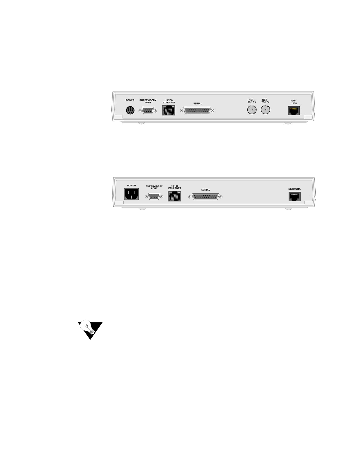
The WANsuite 6130
has five connectors. From left to right these are as
follows:
POWER
,
SUPERVISORY PORT
,
10/100 ETHERNET
,
SERIAL
INTERFACE
,
and
NET
as shown in Figure 1.2 below.
Indicator
Description
MODE
Normally , this indica tor lights
green
.
The indicator lights
amber
while configuration is being set by the fr ont panel
buttons or when the configuration is changed by SNMP or through the Web
interface. The indicator will remain amber until the changed configuration is
saved; it will revert to green when the new configuration has been saved.
NET
This indicator is off (not illuminated) when the Network port has not been
configured.
The indicator lights
green
when the Network port link is up and the ATM
protocol is established.
The indicator lights
red
when the Network port link is down and the ATM
protocol is not established.
The indicator lights
amber
when the Network port link is up but the ATM
protocol is not established.
SERIAL
This indicator is off ( not illuminated) when the port has not been configured.
The indicator lights
green
when the serial port is active.
The indicator lights
amber
when the serial port is not active.
ALARM
This indicator lights
red
if an alarm condition exists.
The indicator lights
amber
if a “yellow” alarm condition exists.
POWER
This indicator lights
green
when power is applied to the unit.
The indicator lights
amber
in test modes (Port looped or BERT active).
Button
Description
RESET
Provides a hardware reset to the unit.
Sets the unit back to its factory default Ethernet or HDLC configuration; this is
the same as a maintenance reset.
To initiate this function, you must press and hold the
button during a
power-up sequence.*
CONFIG
CONFIG
CONFIG
Figure 1.2
MODE
WANsuite 6130 Rear Panel
About the WANsuite 6x30
Page 22
1-6
The rear panel of the WANsuite 6230 has seven connectors. From left to
right, these a re as fo llows :
POWER
,
SUPERVISORY PORT
,
10/100 ETHERNET
,
SERIAL
, and
NET (75
Ω
Rx), NET (75
Tx), NET (120
)
as shown in
Figure
1.3 below. The WANsuite 6230 has one E1 port to which you may connect
using
the 75-ohm BNC
the 120-ohm RJ-48C.
The rear panel of the WANsuite 6430 has five connectors. From left to right,
these are as follows:
POWER
,
SUPERVIS ORY PORT
,
10/100 ETHERNET
,
SERIAL
,
and
NETWORK
as shown in Figure 1.4 below.
Supervisory Port
The
SUPERVISORY
port
is a DB-9 female DCE connector configured for 8
bits, no parity, and 1 stop bit. Bit rates are configured through the Web server
interface. (S ee
on page 3-26.) The Supervisory port speed
can be set to 1200, 2400, 4800, 9600, 19200, 38400, 57600, or 115200 bps.
The initial de fault rate of th e Supervisor y port is 19200 bp s.
On power-up, the Supervisory port sends out diagnostic messages at the bit
rate of 115.2 kbps until the Supervisory service acquires the Supervisory port,
after which the port speed is changed to the setting in the Supervisory
interface screen.
10/100 Ethernet
The WANsuite 6x30
units
p
rovide a single
10/100 ETHERNET
interface for IP
Gateway, SNMP, and Web browse r access. This interf ace is a n eight-pin
modular jack that complies with standard twisted-pair, 10/100Base-T
requirements. The 10/100Base-T cable is supplied by the end user. Refer to
on page A-12 for pin assignments and
cable descriptions.
Ω
Ω
either
Figure 1.3
Figure 1.4
or
WANsuite 6230 Rear Panel
WANsuite 6430 Rear Panel
Supervisory Screen
NOTICE:
For information on pinout assignments for this con nector, refer to
Supervisory Port Pin Assignments on page A-13. See Standard
Equipment on page A-10 for information on cables for this connector.
Ethernet Connection Pi n Assignments
WANsuite 6x30
Page 23

1-7
Ethernet LED Indicators
There are two unlabeled indicator LEDs on either side of the 10/100 Ethernet
jack. The LED on the left side of the jack pulses amber to indicate data
activity (either transmit or receive). The LED on the right side of the jack
lights green to indicate that the link layer is operational.
Serial Interface
The
interface located on
WANsuite 6x30 rear panels is
a multi-
protocol interface presented physically as a DB-25 connection. The protocols
supported by this interface are RS-232, V.35,
EIA-530,
and
(on the 6230
only)
X.21.
Cables tha t adapt the DB- 25 interface to the 34-pin V. 35 interface ar e
available. DB-25 to DB-25 cables are also available if your installation needs
require them . See
on page A-10 for
details. P in
assignments for the Serial interface are
listed in
on page A-11
and
on page A-12
.
Network Interface
The WANsuite 6x30 units have one rear panel
NETWORK
connection
.
On the
WANsuite 6130 and 6430, this connection is a standard RJ-48C, eight- pin
modular jack that terminates as 120 ohms. The WANsuite 6230’s Network
port is accessible through
the 75- or 120-ohm jack. The 75-ohm
connectors are standard BNC jacks, while the 120-ohm connector is a
standard RJ-48C right-pin modular jack. Both 75- and 120-ohm jacks will
receive a signal level to
27 dB to its appropriate termination impedance.
To view the pinout assignments for these interfaces, refer to
on page A-13.
Power Connection
The
POWER
port on the WANsuite 6130 and 6230 units
is an eight-pin
circular mini-DIN connector that connects the autoranging 100–240 VAC or
18−150 VDC external power supply to the unit. The WANsuite 6230 is
intended to be used with a CE Marked power supply with a minimum output
rating of 4.0 A at +5 VDC. The unit has no power switch.
The
POWER
port on the WANsuite 6430 unit
is a standard, grounded, three-
prong connector. This 110/220 VAC power receptacle is rated at 50–60 Hz,
0.2 A/0.1 A. To apply power to the unit, simply plug the supplied power cord
SERIAL
Standard Equipment
Assignments, DTE Mode (Packet Use Only)
Pin Assignments, DCE Mode
Serial Interface Pin
Serial Interface
CAUTION:
Pin Assignments
FCC rules require that interconnecting cables carrying high-speed
data be shielded appropriately to minimize radio frequency
interference.
either
−
Network Int erface
About the WANsuite 6x30
Page 24

1-8
into the unit’s
POWER
port and then connect the wall plug to an appropriate
electrical outlet. The unit has no power switch.
When power is applied to any WANsuite 6x30 unit, the front panel indicators
flash for approximately 10 to 15 seconds as the unit initializes. The green
POWER
LED on the front panel will remain illuminated as long as the unit
receives pow er. This LED turns amber wh en the unit is in te st mode.
CAUTION:
Power Failure
If the indicator does not illuminate, check the power connections and the
primary circuit breaker.
The WANsuite 6x30
units
p
rovide nonvolatile memory retention of the unit
configuration in case of a power failure. The unit will automatically restore
normal service following a power loss and will retain pre-existing time and
date information.
Always connect the power cord to a grounded electrical outlet.
NOTICE:
Per UL 1950 and CSA 950 Clause 1.7.2, if the power supply cord is
intended to serve as a disconnect device, an easily accessible socket
must be installed near the equipment.
WANsuite 6x30
Page 25

2-1
C
HAPTE
R
2
This chapter describes the contents of your WA Nsuite 6x30 shipment and
provides information on connecting and installing the unit.
The WANsuite 6x30 uses an “Installation Wizard” to help you automatically
install the unit quickly and correctly. Procedures for using this Installation
Wizard are also described in this chapter.
Unpacking and Inspection
The WANsuite 6x30 is shipped in cardboard cartons with foam inserts for
shock and vibration protection. When your shipment arrives, inspect the
shipping container and contents, and compare all items w ith those on the
packing list.
If the contents of the shipment are incomplete or if there is mechanical
damage or defect, notify Verilink. (Refer to
page xiv.) If the shipping container or cushioning material is damaged, notify
the carrier and Verilink immediately and make a notation on the delivery
receipt that the container was damaged. (If possible, obtain the signature and
name of the person making delivery.) Retain the packaging material until the
contents of the shipment have been checked for completeness and the unit has
been checked both mechanically and electrically.
NSTALLATION
C
2
I
HAPTER
Support from Verilink
on
Supplied Materials
The WANs uite 6x30 ship s with the follow ing standard items:
•
Serial (Supervisory) cable
•
Network cable
•
Power cord
•
Verilink Documentation CD
Installation
Page 26

2-2
For specific applications, see
on page A-10
and reference
your specific unit (i.e., 6130, 6230, or 6430)
f
or additional optional cables and
adapters. Contact Verilink Technical Support (
page xiv) fo r further assis tance.
Installation Wizard
The WANsuite 6x30 can be configured and monitored through the Web server
interface. To gain access to this inter face, the un it must be co nfigured w ith an
IP address. Verilink provides a DOS-based program – the Verilink
Configuration Wizard – to aid in this initial configuration.
Y
.
To configure the IP address using the Verilink Configuration Wizard, perform
the followi ng steps:
Using the supplied cable, connect the unit’s DB-9 Supervisory port to a
COM port on your PC. (Take note of which COM port is connected.)
Insert the Verilink CD (provided with the WANsuite 6x30) into your PC’s
CD-ROM drive.
Use Windows “Explore” to view the contents of the CD and select the
folder labeled “Utilities.” In this folder will be a file named
;
this executable file is the Verilink Configuration Wizard application.
Double-click on this file to launch the program. After the program is fully
launched, you will see the following screen:
Using the Tab key to move from fie ld to fi eld, move t he cursor to the “ COM
Port” field. Using the Spacebar, toggle between the available options until
the correct COM port is shown (COM1, COM2, COM3, or COM4). Be sure
to choose the same COM port as the port to whic h the unit is connected.
By default, the “Baud Rate” f ield will di splay 115200 (bit s per se cond). For
the purpose of this installation, do not change the displayed baud rate from
its default. Proceed direct ly to the next step .
Optional Equipment
NOTICE:
1
2
3
ou may also access the Verilink Configuration Wizard on the
Verilink Web site: www.verilink.com
ipwiz.exe
4
5
WANsuite 6x30
Page 27

2-3
6
Using the Tab key again, move the cursor to the “IP Address” field and
enter the appropriate IP address for the unit (
). If necessary,
repeat this process for the “Subnet Mask” and “Gateway Address” fields.
Next, move the cursor to the “Write To Unit” field and press the Enter key.
The program will prompt you to reset the unit.
To reset the unit, press the
button on the unit’s front panel. The
Configuration Wizard will then automatically download the configuration
information to the unit.
Note the status messages displayed at the bottom of the Configuration
Wizard screen. When the download is complete, your PC will beep and the
status message bar will display “Finished.”
Finally, move the cursor to the “Exit” prompt and press Enter. The
Configuration Wizard program will close.
xxx.xxx.xxx.xxx
7
8
9
10
RESET
Installation
Page 28

2-4
WANsuite 6x30
Page 29

3-1
C
HAPTE
R
3
C
HAPTE
R
3
W
E
B
S
ERVER INTERFAC
E
The WANsuite 6x30 product family supports the major SNMP Management
Information Bases (MIBs) that make configuration standard and easy to
manage. The MIBs may be accessed in a variety of ways. One is to use a
standard MIB browser of your choice (such as HP OpenView). A second is
through the intelligent Web Server interface that resides in your WANsuite
unit's internal memory. The Web Server interface and how it’s used to
configure your WANsuite unit are described in detail below.
In cases where all WANsuite 6x30’s unit Web Server configuration screens
are the same, only the 6130 screens are displayed. However, where the
configuration screens of the units differ, as in the case of the Network
Interface screens and their submenus, each unit’s configuration screens are
displayed. Even when all screens resemble each other, parameter values and/
or defaults may vary from unit to unit; these differences are noted.
Accessing the Web Server Interface
You can acce ss the Web Server in terface by connect ing to its IP addres s. This
connection can be directly through the 10/100 Ethernet port, PPP over the
Supervisory port, or in-band via RFC 1483 encapsulated IP traffic on the
ATM circuit.
NOTICE:
To view th e Web Ser ver inte rface, use
Microsoft’s Internet Explorer 5.0 or
higher
.
Any changes to the unit’s configuration MUST be followed by a
“Submit” (if there is a “Submit” button on the screen) and a “Save and
Restart” for the changes to take effect.
NOTICE:
Verilink recommends
you use other Internet browsers to access the Web Server interface,
screen elements will not display as described in this manua l.
Microsoft’s Internet Explorer 5.0 (or higher). If
Web Server Interface
Page 30

3-2
To access the Web Server interface, enter (by typing) the unit’s IP address in
the browser’ s Address (or L ocation) fie ld and press th e “Enter” key.
Another method for accessing the Web server configuration screens is to
establish a PPP connection through the unit’s Supervisory port. To use PPP
on the Supervisory port, set up a PC running Windows 9
x
/NT for Dial-up
Networking with a NULL modem driver, and establish a PPP connect ion.
Then open your Web browser and direct it towards the Port’s IP address.
Layout of Interface Screens
When you first access the Web Server interface, your browser will display a
screen that is divided into three frames. The upper frame forms a border
across the top of the screen; it identifies th e Verilink uni t in service and
displays the hardware and software revision and serial numbers under which
the unit is operating.
The area beneath the upper frame is divided into two side-by-side frames. The
frame on the le ft side
, the navigation pane,
depicts a hierarchical “tree”
structure used to navigate through the various interface screens. Each
“branch” on the tree guides you to more specific upper-level information
about the unit and its configuration. Note that the Interfaces, Applications, and
Utilities branches do not link to an actual displa yed page
these bra nches ar e
simply used to provide structure for navigation.
The frame on th e right side of
the screen displays the configuration screen. The screen captures throughout
this chapter show only the configuration portion of the screen, except in the
case of the Unit screen, which shows all three frames. The Unit screen
represents the top of the navigation tree.
Unit Screen
The first scree n displayed b y the unit’s Web Server interface is the Unit
screen (Figure 3.1). This screen lets you view and set specific information
about the unit in service.
−
WANsuite 6x30
Page 31

3-3
Figure 3.1
The Unit screen displays the following fields:
The Unit screen provides the following user-activated buttons:
Field
Function
Object ID
Display-only field used to point an SNMP agent to this ID.
Up Time
Displays the amount of time the unit has been up and running.
Contact
Stores the name of a point-of-contact for system failure.
Name
Read/write field that holds the unit’s name.
Location
Read/write field that holds the unit's location.
FrameStart ID
Read/write field that holds the unit's ID that uniquely identifies the
unit and is used in the FrameStart applications.
Blank Fields
Read/write fields for user-specific labels and values. Information
resides in non-volatile memory.
Time
Read/write field that holds the unit's internal time setting in
standard 24-hour HH:MM:SS format.
Date
Read/write field that holds the unit's internal date setting in
standard M M/DD/YY format.
Button
Function
Submit
Sets any values that have been changed. Use the top “Submit”
button to set unit parameters changed in the upper section of the
screen, and the lower “Submit” button to set the real-time clock.
Maintenance Reset
Resets unit to its default Ethernet or HDLC configuration.
Unit Screen
Web Server Interface
Page 32

3-4
Maintenance Reset
Use this button to perform a Maintenance Reset. All configurations will be
lost and the unit will be set back to the factory default Ethernet or Serial
HDLC configuration. Either default configuration will set up an ATM service
on the Network port, using one configured virtual channel (VPI=0, VCI=32).
Management d ata receiv ed on th is ATM cha nnel (eith er Web or SNMP) wi ll
be processed at the unit if it is encapsulated using RFC 1483 and directed to
the unit’s IP address. (A Maintenance Reset will not change the unit’s IP
address.) The default serial HDLC configuration will also accept PPPoA
encapsulated data and deliver it to the Serial port. Clicking the “Maintenance
Reset” button will display a confirmation screen (Figure 3.2) with the option
to perform either an Ethernet or Serial HDLC reset.
Figure 3.2
Save and Restart
The Save and Restart button on the Unit screen will display the confirmation
screen sh own in
Figure 3.3.
Save and Restart
Saves the current configuration and restarts the unit.
Refresh
Refreshes data on the current page.
Button
Function
Maintenance Reset Screen
WANsuite 6x30
NOTICE:
Performing a “Maintenance Reset” or a “Save and Restart” will
terminate communications with the unit. A “Refresh” should be
performed after approximately 10 seconds to restore communications.
Page 33

3-5
Figure 3.3
Click the “Save and Restart” button on the confirmation screen to proceed
with the action. To cancel, simply invoke your browser’s “Back” function.
Interfaces
Each WANsuite 6x30 unit has four available interfaces: Network, Serial,
Ethernet 10/100, and Supervisory. These interfaces are described below.
WANsuite 6130 (T1 Interface) and 6230 (E1 Interface)
Network Screens
The WANsuite 6130 Network screen (Figure 3.4) lets you view and make
changes to the Network interface’s configuration as described below. In
addition, this screen provides a table that displays error status and alarm
thresholds fo r the Network interfaces.
Save and Restart Screen
Figure 3.4
WANsuite 6130 Network Screen
Web Server Interface
Page 34

3-6
Framing
Selects the framing for the Network side of the DSU/CSU.
Values
ESF, D4
Default:
ESF
Coding
Sets the Network side line coding.
Values:
AMI, B8ZS
Default:
B8ZS
Line Build-O ut
Sets the trans mit Line Build O ut (LBO) for the Network inte rface.
Values:
0, −7.5, −15.0,
−
22.5 dB
Default:
0 dB
Timing
Sets the timing source to synchronize the unit’s internal timing generators. In
all cases, slips are controlled to occur on frame boundaries at the Network
port when timing synchronization is lost.
Definitions of the timing sources are as follows:
Internal
– The unit’s internal frequency standard (T1 1.544 Mbps ± 50 bps)
is used for all timing.
Network
– Timing is derived fr om the Network port recovered clock.
Zero Suppression
Determines whether ones de nsity insertio n is activated after 15 zeros. T his
parameter is ignored if the Coding parameter is set to “B8ZS.”
Values:
Disable, Enable
Default:
Disable
PRM Enable
Lets you establish which performance messaging standard will be employed
to initiate Per formance Re port Message (P RM) function s. Setting thi s field to
“Enable” instructs the unit to use ANSI T1.403, which sends a PRM once
every second . Setting this field to “Disab le” instruc ts the unit to use AT&T
TR54016, which provides performance reporting on request only.
Values:
Disable, Enable
Default:
Disable
Error Status and Alarm Thresholds Table
The unit can be programmed to generate an alarm condition based on a
specific level of performance degradation. The Network screen presents a
table that provides current error status and alarm threshold information.
Acceptable alarm thresholds are set for periods of 15 minutes (900 seconds)
and sampled every second. The error types listed in the paragraphs below can
be preset to a value between 0 and 900 seconds. Setting a field to “0” (zero)
disables the alarm on that statistic. To effectively disable alarm reporting, set
all fields to “ 0” (zero).
The 15-minute time frame is not based on the TR 54016 or T1.403 interval
boundaries, but is a time window based on the accumulated counts over the
previous fifteen 1-minute intervals. In all cases, if the number of actual
WANsuite 6x30
Page 35

3-7
network errored seconds in the previous 15 minutes reaches the preset
threshold for the specified error type, an alarm condition is declared.
The four columns of the status table are as follows:
The table prov ides error st atus and alarm threshold in formation fo r the
following e rror para meters:
ES
Sets the Errored Seconds threshold. An ES is a 1-second period in which at
least one logic error occurred. The default value is 45 seconds.
SES
Sets the Sev erely Errored Seconds th reshold.
An SES
is a
1-second pe riod in
which at least 320 Cyclic Redundancy Check (CRC) errors or one Out - of -
Frame (OO F) error occur red.
The default value is 5 seconds.
LOSS
Sets the Loss of Signal Seconds threshold. A LOSS is a
1-second period in
which the T1 received signal is interrupted
. The default value is 5 seconds.
UAS
Sets the Unavailable Seconds threshold. A UAS is a
1-second period in which
consecutive severely errored seconds cause an unavailable state
. The default is
0 (zero) seconds (Disabled).
CSS
Sets the Controlled Slip Seconds threshold. The default 5 seconds.
BPVS
Sets the Bipolar Violation Errored Seconds threshold. A BPVS is a 1-second
period in which at least one bipolar violation occurred. The default is 0 (zero)
seconds (Disabled).
OOFS
Sets the Out-of-Frame Seconds threshold. An OOFS is a
1-second period in
which a frame sync loss occurred
. The default value is 5 seconds.
AISS
Sets the Alarm Indication Signal Seconds threshold. An AISS is a 1
-second
period when unframed all ones are received.
The default is 0 (zero) seconds
(Disabled).
RAS
Sets the Remote Alarm Seconds threshold.
A RAS is generated by the
terminal equ ipment when an improper sig nal is receiv ed from the fac ility (or
upon receipt of unframed all ones).
The default is 0 (zero) seconds (Disabled).
Reset Tim er
Sets the Reset Timer threshold. This field is the contiguous number of
seconds that an alarm parameter must be clear before the alarm is reset.
•
Status
Displays the current status of the Network port.
•
Alarm
Displays the alarm value of the Network port. The unit
declares an alarm as soon as the count exceeds the threshold
set.
•
Count
Displays the number of eve nts or occurren ces of this stat istic
that have been detected.
•
Threshold
A read/write field that can be set to a desira ble threshold .
Web Server Interface
Page 36

3-8
Applicable values range from 000 through 900. A value of “000” means the
alarm will never be reset. Default is 30 seconds.
The Network screen provides the user-activated buttons described in the table
below.
CAUTION:
Performance Screens
Click on the “Performance” button at the bottom of the Network screen to
bring up a Netw ork Perform ance/Summa ry table. In ad dition to the er ror
parameters found in the
on
page 3-6, the error parameters described below are included on the Network
Performance/Summary table. From this screen, you can access the Network
Performance 24 Hour screen (Figure 3.6) or the Network Performance 30 Day
screen (
Figure 3.7).
Button
Function
Submit
Sets any values that have been changed.
Clear Alarms
Resets the alarm conditions and counts to zero.
Performance
Displays a Performance/Summary screen (
Figure 3.5) that
shows a current count of the number of error events that have
occurred over the past 24 hours and the past 30 days.
Channels
Displays the Channel Table Details screen, showing each
channel by index number. Each channel’s rate and service (by
number) are displayed and can be changed through user input.
Network Services
Displays the Services screen for the Network interface.
Refresh
Refreshes data on the current page.
Performance data will be lost upon power cycle or after performing a
Maintenance Reset or a Save and Restart.
Error Status and Alarm Thresholds Table
WANsuite 6x30
Page 37

3-9
Figure 3.5
BES
Sets the Bursty Error Seconds threshold. A BES is a 1-second period during
which more than one but fewer than 320 CRC6 errors occurred.
LOFC
The Loss of Fr ame Count rep resents the nu mber of times a loss of frame i s
declared. A loss of frame is declared after 2.5 seconds of continuous loss of
signal or OOF.
CRCES
Sets the Cyclic Redundancy Check Errored Seconds threshold. A CRC is a
method of confirming the integrity of received data.
Network Performance/Summary Screen
Figure 3.6
Network Performance 24 Hour Screen
Web Server Interface
Page 38

3-10
Figure 3.7
Some of the parameters across the top of the WANsuite 6230 Network screen
(Figure 3.8) differ from those on the 6130 Network screen. The parameters at
the top of the 6230 Network screen are described below.
Framing
Selects the framing for the Network side of the DSU/CSU.
Values
CCS, CAS, Unframed
Default:
CCS
Coding
Sets the Network side line coding.
Values:
HDB3, AMI
Default:
HDB3
Timing
Sets the timing source to synchronize the unit’s internal timing generators. In
all cases, slips are controlled to occur on frame boundaries at the Network
port when timing synchronization is lost.
Network Performance 30 Day Screen
Figure 3.8
WANsuite 6230 Network Screen
WANsuite 6x30
Page 39

3-11
Definitions of the timing sources are as follows:
Internal
– The unit’s internal frequency standard (E1 2.048 Mbps ± 50 bps)
is used for all timing.
Network
– Timing is derived fr om the Network port recovered clock.
CRC4 Mode
Provides line integrity detection to determine if bit errors are present on the
line.
Values:
Disable, Enable
Default:
Disable
The Error Status and Alarm Threshold Table (page 3-6) and the Performance
Screens (page 3-8) related to the 6230 Network screen are the same as those
related to the 6130 Network screen.
WANsuite 6430 (G.SHDSL) Network Screen
The WANsuite 6430 Network screen (Figure 3.9) lets you view and make
changes to the Network interface's configuration. In addition, this screen
provides a ta ble that displ ays the alarm v alues for the Network inte rface.
Figure 3.9
The Network screen configuration parameters are described in the following
paragraphs.
Unit Type
Selects the unit type. T U-R repre sents a CP E termina l unit; TU- C represen ts a
CO terminal unit.
Values:
TU-R, TU-C
Default:
TU-R
Expected R epeaters
Provisions the number of repeaters in the selected span.
Values:
0 (zero)
Default:
0 (zero)
WANsuite 6430 Network Screen
Web Server Interface
Page 40

3-12
Span Configuration
Represents a span configuration profile in the Span Configuration Profile
Table, which applies to this span. By default, this object will have the value
“DEFVAL” (the index of the default profile).
Values:
User Span Profile 1, User Span Profile 2, DEFVAL (Default
Value)
Default:
DEFVAL
Span Alarm
Configuration
Represents an Alarm configuration profile in the Endpoint Alarm
Configuration Profile Table. The alarm threshold configuration in the
referenced profile will be used by defaul t for all segm ent endpoint s in this
span. Individual endpoints may override this profile by explicitly specifying
some other profile in the table. By default, this object will have the value
'DEFVAL' (the index of the default profile).
Values:
User Alarm Profile 1, User Alarm Profile 2, User Alarm
Profile 3, DEFVAL (Default Value)
Default:
DEFVAL
Status
Provides overall status information of the span.
Detail Status
Displays current activity status of the network.
EOC In
Displays the Embedded Operations Channel In.
EOC Out
Displays the Embedded Operations Channel Out.
Discovered Repeaters
Displays the number of discovered repeaters in this span.
Line Rate
Displays the actual negoti ated line rate .
Maximum Line Rate
Displays the maximum physical line rate.
Transmission Mode
Displays the actual transmission mode (Annex-A or Annex-B).
The Network screen provides the user-activated buttons described below.
CAUTION:
Button
Function
Submit
Sets any values that have been changed.
Network Services
Displays the Services screen for the Network interface.
Configuration Profiles
Displays the three configuration profiles that can be used.
Alarm Profiles
Displays the five alarm profiles that can be used.
Span Endpoints
Lists the currently available span endpoints.
Refresh
Refreshes data on the current page.
WANsuite 6x30
Performance data will be lost upon power cycle or after performing a
Maintenance Reset/Restart.
Page 41

3-13
Network Services
The Network Services screen (Figure 3.10) displays the Service Index,
Interface, Type, and Pair pa rameters f or each a ctive Net work serv ice.
Figure 3.10
Service Details Button
From this screen, you can access and change the Interface and Type
parameters for the Network service.
In addition, the Service Details screen provides the following user-activated
buttons:
Interface Details Button
Clicking the “Interface D etails” butto n on the Netwo rk Services sc reen lets
you view i nterface p arameters for the N etwork s ervice.
Type Details Button
Clicking the “Type Details” button on the Network Services screen will let
you view ( and, in s ome cases, change) interface paramete rs for the Network
service.
Configuration Profiles
Clicking on the “Configuration Profiles” button on the Network screen will
display the screen shown in
Figure 3.11.
Button
Function
Submit
Sets any values that have been changed.
Interface Details
Opens the Details screen for the Interface of the Network service
(see below).
Type Details
Opens the Details screen for the Type of the Network service (see
below).
Delete Service
Opens the Verify Delete Service screen.
Refresh
Refreshes data on the current page.
Network Services Screen
Web Server Interface
Page 42

3-14
Figure 3.11
The table on th is screen displa ys the followi ng informati on for each availa ble
Span Configuration Profile:
Span Config P rofile
Name
Name of the defined span configuration profile.
Span W ire Interface
Type of wire interface used by the span.
Span M in Line R ate
Minimum attainable line rate in the span.
Span M ax Line Rate
Maximum atta inable lin e rate in t he span.
Span Rem ote Enabled
Indicates whether the option to span remote is enabled or disabled.
Span Config
Transmission Mode
Regional setting of the span. The possible settings are Annex-A (ITU-T
G.991.2), Annex-B (ITU-T G.991.2).
In addition to the table, this screen has a “Configuration Profile Details”
button. Clicking on this button will display additional detailed information on
a selected co nfiguratio n profile. This screen is des cribed in more detail in the
paragraphs below.
Select the particular profile for which you want to see details by clicking on
the radio button beside the Span Config Profile Name on the Configuration
Profiles screen and then clicking on the “Configuration Profile Details”
button. The Configuration Profile Details screen (Figure 3.12) supports the
overall configuration of the spans.
Configuration Profiles Screen
WANsuite 6x30
Page 43

3-15
Figure 3.12
This screen lets you configure or change the following information about the
selected configuration profile:
P ro file N a me
A 32-character string that identifies a Profile Name in the Span Profile table.
Each entry represents the complete span in an ATM line.
Wire Mode
Displays the type of wire interface used by the span (two-wire).
Data Rate (M in)
Sets the minim um attainabl e line rate in the s pan.
D ata R a te (Max )
Sets the maximum attainable line rate in the span.
Remote
Enables/disables support for remote management of the units in an SHDSL
line from the S TU-R via the E OC.
Values:
Enabled, Disabled
Default:
Enabled
Transmission Mode
Sets the regional setting of the span represented as a bit-map of possible
settings.
Values:
Annex-A
, Annex-B
Default:
Annex-B
To set any configuration profile parameter, enter the desired value/information
in a field or select the desired parameter from one of the pull-down lists, and
then click on the “Submit” button.
Alarm Profiles Screen
Clicking on the “Alarm Profiles” button on the WANsuite 6430’s Network
screen will display the screen shown in Figure 3.13.
Configuration Profile Details Screen
(ITU-T G.991.2)
(ITU-T G.991.2)
Web Server Interface
Page 44

3-16
Figure 3.13
The Alarm Profiles screen displays the current status of endpoint alarms.
Information is displayed for the following alarm parameters:
Endpoint Alarm
C o n fig Pro file Na me
Displays the unique index associated with this Endpoint Alarm profile.The
values are obtained from the alarm configuration profile referenced by this
object. The value of this object is the index of the referenced profile in the
Line Alarm Configuration Profile Table, or NULL (a string of length 0). If
the value is NULL, the endpoint uses the default Alarm Configuration Profile
for the associa ted span. Th e default value of this object is NULL.
Endpoint Thresh Loop
Attn
Indicates the loop attenuation threshold has been reached/exceeded for the
selected segment endpoint.
Endpoint Thresh SNR
Margin
Indicates the Signal-to-Noise Ratio margin threshold has been reached/
exceeded for the selected segment endpoint.
Endpoint T hresh ES
Indicates the Errored Seconds threshold has been reached/exceeded for the
selected segment endpoint.
Endpoint SES
Indicates the Severely Errored Seconds threshold has been reached/exceeded
for the selected segment endpoint.
Endpoint T hresh CR C
Indicates the Cyclic Redundancy Check anomalies threshold has been
reached/exceeded for the selected segment endpoint.
Endpoint T hresh
LOSWS
Indicates the Loss of Sync Word Second threshold has been reached/exceeded
for the selected segment endpoint.
Endpoint Thresh UAS
Indicates the Unavailable Seconds Threshold has been reached/exceeded for
the selected segment endpoint.
In addition to the alarm status table, the Alarm Profiles screen has an “Alarm
Profile Details” button.
Alarm Profiles Screen
WANsuite 6x30
Page 45

3-17
Alarm Profile Details Screen
Clicking on the “Alarm Profile Details” button displays the screen shown in
Figure 3.14. The table on this screen lets you create/delete the associated
entry in this table (profile name), and configure the alarm threshold values to
be used for the selected segment endpoint.
Figure 3.14
P ro file N a me
Displays the unique index associated with this Endpoint Alarm profile. A new
Alarm Profile can be created by entering a unique name for the profile in this
field and then, after configuring the desired alarm thresholds, clicking on the
“Submit” button.
Loop Attenuation
Sets the loop attenuation alarm threshold. If the current value reaches or drops
below this threshold, a crossing trap is generated.
SNR M argin
Sets the Signal-to-Noise Ratio margin alarm threshold. When the current SNR
value reaches or drops below this threshold, a crossing trap is generated.
ES
Sets the threshold for the number of Errored Seconds within any given 15-
minute performance data collection interval. If the value of ES in a particular
15-minute co llection in terval reache s/ exceeds this value, a trap is generated.
One trap will be sent per interval per endpoint.
SES
Sets the threshold for the number of Severely Errored Seconds within any
given 15-minute performance data collection interval. If the value of SES in a
particular 15-minute coll ection inter val reaches/e xceeds this va lue, a trap is
generated. One trap will be sent per interval per endpoint.
CRC
Sets the threshold for the number of Cyclic Redundancy Check anomalies
within any given 15-minute performance data collection interval. If the value
of CRC anomalies in a particular 15-minute collection interval reaches/
exceeds this value, a trap is generated. One trap will be sent per interval per
endpoint.
LOSWS
Sets the threshold for the number of Loss of Sync Word Seconds within any
given 15-minute performance data collection interval. If the value of LOSW
Alarm Profile Details Screen
Web Server Interface
Page 46

3-18
in a particul ar 15-minute collection int erval reach es/exceeds th is value, a trap
is generated. One trap will be sent per interval per endpoint.
UAS
Sets the threshold for the number of Unavailable Seconds within any given
15-minute performance data collection interval. If the value of UAS in a
particular 15-minute coll ection inter val reaches/e xceeds this va lue, a trap is
generated. One trap will be sent per interval per endpoint.
NOTICE:
Span Endpoints Screen
Clicking on the “Span Endpoints” button on the WANsuite 6430 Network
screen will display the screen shown in Figure 3.15.
This screen displays each side of the span, with the local side displayed first.
If the SHDSL link is not up, only the local side of the span is displayed. The
EOC channel is used to acces s the remote end unit
Clicking on the highlighted (linking) Type identifier in the table on the Span
Endpoints screen will display the Span Endpoints Details screen (Figure 3.16).
This table supports retrieval of unit inventory information available via the
EOC from units in an SHDSL line, and provides details regarding the
parameters listed below.
Any changes to the above-listed parameters must be followed by a
“Submit” for the changes to take effect.
Figure 3.15
Span Endpoints Screen
WANsuite 6x30
Page 47
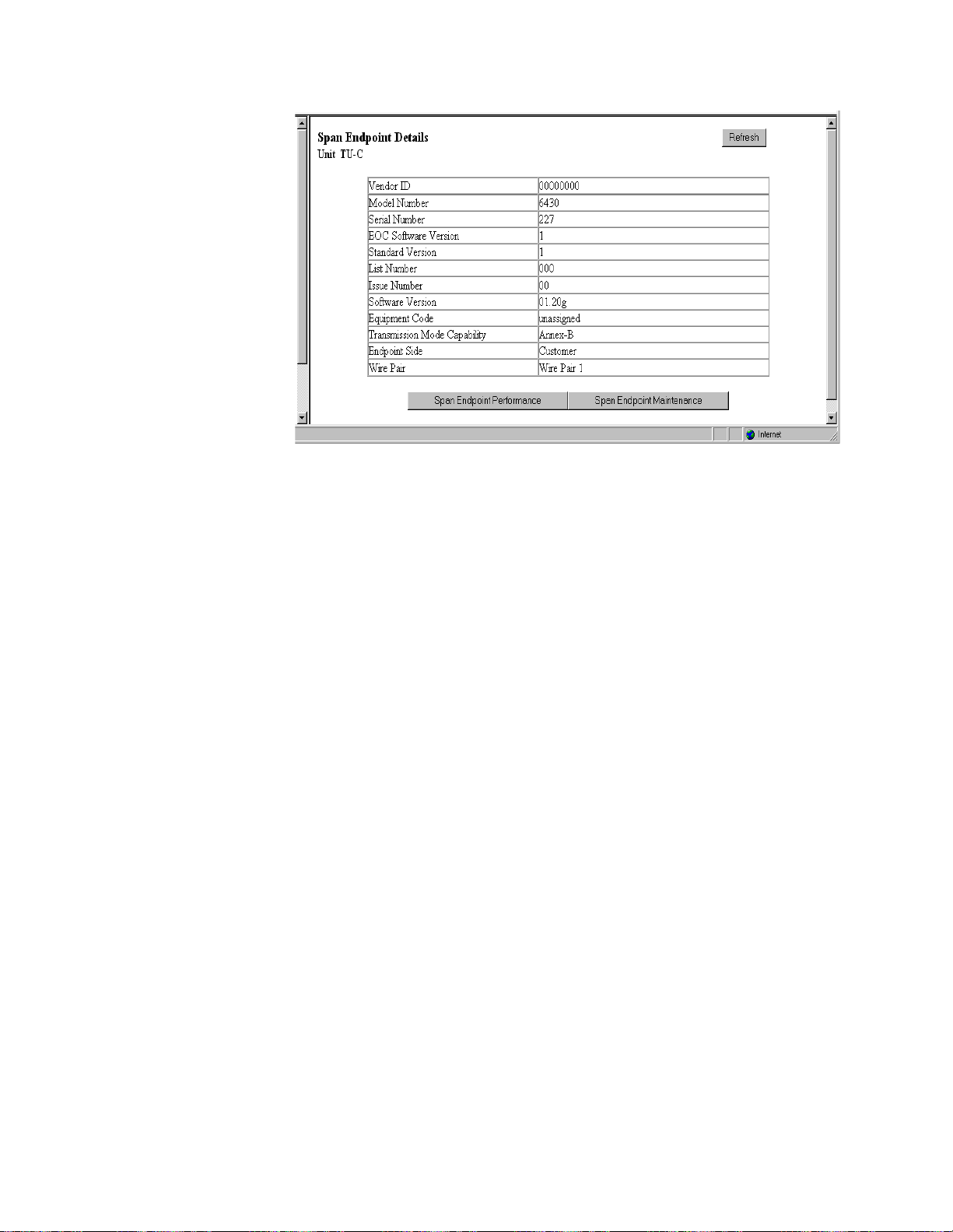
3-19
Figure 3.16
Ve n dor ID
Displays the Vendor ID as reported in an Inventory Response message.
Model Number
Vendor model number as reported in an Inventory Response message.
Serial Num ber
Vendor serial number as reported in an Inventory Response message.
EOC Software Version
Vendor EOC version as reported in a Discovery Response message.
Standard Version
Version of the SHDSL standard implemented as reported in an Inventory
Response message.
List Num ber
Vendor list number as reported in an Inventory Response message.
Issue N u m b er
Displays the Vendor issue number as reported in an Inventory Response
message.
Software Version
Displays the Vendor software version as reported in an Inventory Response
message.
Equipment Code
Equipment code conforming to ANSI T1.213, Coded Identification of
Equipment Entities.
Transm ission
Mod eCap a b ility
Transmissi on mode cap ability of th e SHDSL unit.
Endpoint Side
Defines whi ch direction the SHDSL por t is pointing. Normal opera tion will
use the TU-R configuration, and the endpoint will be “Network.” When unit
type is TU-C, endpoint will be “Customer.”
Wire Pair
Always “Wire Pair 1.”
Span Endpoint Details Screen
Web Server Interface
Page 48

3-20
Clicking on the “Span Endpoint Performance/Summary” button on the Span
Endpoint Details screen will display the screen shown in Figure 3.17.
Figure 3.17
This screen displays information on the performance and error status of the
span endpoints. This information is provided in summary form for complete
totals as well as for current 15-minute and 1-day intervals.
Status
Current state of the endpoint. This is a bit-map of possible conditions. The
various bit positions are as follows:
1 (noDefect)
There no defects on the line.
2 (powerBackoff)
Indicates enhanced Power Backoff.
4 (deviceFault)
Indicates a vendor-dependent detection of diagnostics or
self-test results.
8 (dcContinuityFault)
Indicates vendor-dependent conditions that
interfere with span powering such as short and open circuits.
16 (snrMarginAlarm)
Indicates that the SNR margin has dropped below
the alarm threshold.
32 (loopAttenuationAlarm)
Indicates that the loop attenuation has
dropped below the alarm threshold.
64 (loswFailureAlarm)
Indicates a forward LOSW alarm.
128 (configInitFailure)
Endpoint failure during initi alization due to pai red
endpoint not able to support requested configuration.
256 (protocolInitFailure)
Endpoint failure during initialization due to
incompatible protocol used by the paired endpoint.
512 (noNeighborPresent)
Endpoint failure during initializat ion due to no
activation sequence detected from paired endpoint.
1024 (loopbackActive)
A loopback is currently active at this Segment
Endpoint.
SNR M argin
Current Signal-to-Noise Ratio margin for this endpoint as reported in a Status
Response/SNR message.
Span Endpoint Performance/Summary Screen
−
−
−
−
−
−
−
−
−
−
−
WANsuite 6x30
Page 49

3-21
Attenuation
Current loop attenuation for this endpoint as reported in a Network or
Customer S ide Per formance Status message.
ES
Count of Errored Seconds on this endpoint since the unit was last restarted.
SES
Count of Severely Errored Seconds on this endpoint since the unit was last
restarted.
CRC
Count of Cyclic Redundancy Check anomalies on this endpoint since the unit
was last rest arted.
LOSWS
Count of Loss of Sync Word Seconds on this endpoint since the xU was last
restarted.
UAS
Count of Unavailable Seconds on this endpoint since the xU was last
restarted.
Tim e Elapsed
Total elapse d seconds in the current 15- minute interv al.
15-Minute and 1-Day Intervals
Also included on this screen are buttons used to display the span endpoint
performance summaries for 15-minute intervals and for 1-day intervals. These
screens display only a summary of the errors (ES, SES, CRC, LOSWS, UAS)
that have occurred on the span during the interval selected.
The 15-Minute Intervals table provides one row for each endpoint
performance data collection 15-minute interval. The 1-Day Intervals screen
provides one row for each endpoint performance data collection 24-hour
interval.
Span Endpoint Maintenance Screen
Clicking on the “Span Endpoint Maintenance” button from the Span Endpoint
Details screen will display the screen shown in Figure 3.18. This table supports
maintenance operations (e .g., loopbacks) to be performed on segment
endpoints.
Figure 3.18
The Span Endpoint Maintenance parameters are described below.
Span Endpoint Maintenance Screen
Web Server Interface
Page 50

3-22
Loopback
Specifies loopbacks for the associated segment endpoint.
Values:
No Loopback, Normal Loopback
Default:
No Loopback
NOTICE:
Tip Ring Reversal
Indicates the state of the tip/ring pair at the associated segment endpoint.
Loopback Tim eout
(m inu tes )
Specifies the timeout value in minutes for lo opbacks initia ted at segmen ts
endpoints contained in the associated unit. A value of 0 disables the timeout.
Restart Endp oint
Enables t he manag er to trig ger a so ft restar t of the SHDSL li ne at th e
associated segment endpoint. The manager may only set this object to the
“restart” value to initiate a restart. The agent will perform a restart after
approximately 5 seconds, and restore the object to the “ready” state.
Values:
Ready, Restart
Default:
Ready
Power Source
Indicates the DC power source being used by the associated unit.
Serial Screen
The Serial screen (Figure 3.19) lets you view and make changes to the unit’s
Serial interface configuration as described in the paragraphs below. To make
changes to any Serial port parameter, simply set the parameter to the desired
selection and press the “Submit” button.
At the time of this release, only the Normal Loopback option is
implemented for the WANsuite 6430.
Figure 3.19
Serial Scr een
WANsuite 6x30
Page 51

3-23
Typ e
Selects the type of interface (based on its electrical signal characteristics) used
by the equipment connected to the Serial port.
Values:
V.35, RS-232, EIA-530, and (6230 only) X.21
Default:
V.35
NOTICE:
Mode
By default, the Serial port serves as a DCE port. However, the Serial port can
serve as a DTE port.
If the Serial port connects to a DTE device (such as a FRAD or a router), the
Mode parameter must be set to “DCE.” If this port connects to a DCE device
(such as a DSU/C SU), this para meter must b e set to “DTE.”
Values:
DCE, DTE
Default:
DCE
Packet R ate
Packet Rate must be configured to the desired port speed (in bits per second).
Values:
nx 64 kbps (where n = 1–32) or nx56 kbps (where n = 1
31)
Default:
1536 kbps
Values:
n x 64 kbps (where n = 1–32) or nx56 kbps (where n = 1
31)
Default:
1984 kbps
Values:
x 64 kbps (where
= 1–36) or
x56 kbps (where
= 1−31)
Default:
2048 kbps
Tx Clock
Selects the clock the unit uses to sample the data transmitted from the DTE.
When set to “Internal,” the data is sampled directly with the transmit data
clock that is also supplied to the DTE as Transmit Clock. The “External”
option uses the external clock from the DTE.
Values:
Internal, E xternal
Default:
Internal
LL
The Local Loopback parameter can be set to “Enable” or “Disable.” Selecting
“Enable” allows the unit to go into Local Loop when the LL pin on the
Serial 1 port goes high. The unit exits the loop when the LL pin goes low. If
you select “Disable,” the unit ignores the LL pin on the Serial port.
Values:
Disable, Enable
Default:
Disable
V.35 requires the use of an optional cable. Refer to "Optional
Equipment" on page A-10 for ordering information.
NOTICE:
6130:
6230:
6430:
DTE mode requires the use of an optional DTE cable. Refer to
"Optional Equipment" on page A-10 for ordering information.
n
n
n
n
−
−
Web Server Interface
Page 52

3-24
V54
Selecting “Enable” allows the unit to respond to in-band V.54 loop codes. If
you select “Disable,” the unit ignores these codes.
Values:
Disable, Enable
Default:
Disable
CTS
The Clear To Send can be set to “Forced True,” “Forced False,” or “Internal.”
If this parame ter is set to “Intern al,” the C TS contr ol lead fol lows the R equest
to Send (RTS) control lead from the DTE after a delay of a duration
established by the RTS/CTS Delay parameter (see
RTS/CTS Delay
on
page 3-24).
Values:
Forced True, Forced False, Internal
Default:
Forced True
DSR
Data Set Ready can be set to “Forced True,” “Forced False,” or “Internal.”
The “Internal” option sets DSR “On” if the port is enabled and “Off” if the
port is disabled.
Values:
Forced True, Forced False, Internal
Default:
Forced True
DCD
Data Carrier Detect can be set to “Forced True,” “Forced False,” or
“Internal.” If set to “Internal,” DCD is “On” when network carrier is being
received from the remote end, and is “Off” when network carrier is not being
received from the far end.
Values:
Forced True, Forced False, Internal
Default:
Forced True
RTS
Request To Send determines the source from which the unit reads the RTS
signal status. If set to “Normal,” the unit gets RTS from the DTE on the
Serial interface. If set to “Forced True,” RTS is always perceived as “On.”
Values:
Normal, Forced True
Default:
Normal
RTS/CTS D elay
Request To Send/Clear To Send determines how long the unit waits before it
changes the level of CTS to match RTS when the CTS parameter is set to
“Internal.”
Values:
Normal (~30 ms delay), Long (~100 ms delay)
Default:
Normal
Current Pin Status
Displays the Current Pin Status of the DTE Serial port pins.
DTR Alarm Control and Status Table
In addition to the configurable fields, the Serial screen displays a table that
lets you set the Data Termina l Ready (DTR) Alarm Control parameters an d
view the current DTR Alarm Status.
Choices for DTR Alarm Control are “Enable” and “Disable”; the default
setting is “Disable.” Setting DTR Alarm Control to “Enable” allows the unit
to generate an alarm upon loss of DTR, which occurs when the Serial port
detects that the DTR signal is low. The DTR Status field indicates the current
state of the DTR alarm.
WANsuite 6x30
Page 53

3-25
The Serial screen provides the following user-activated buttons:
To make chang es to a Serial port p arameter, si mply set the para meter to the
desired selection and press the “Submit” button.
10/100 Ethernet Screen (IP Service Details)
The 10/100 Ethernet (IP Service Details) screen (Figure 3.20) lets you
configure the IP parameters described below.
Figure 3.20
Unit IP Address
A unique Network address assigned to this unit.
Subnet Mask
Defines the Network portion of the unit’s IP address.
Gateway IP Address
IP address of the default gateway (router) on the LAN side of the unit.
DHCP Client
If DHCP Client is enabled at power-up, the unit will request its IP, Mask, and
Gateway addresses from a DHCP server located on the LAN side of the unit,
and the unit will use these addresses. If the DHCP request is unsuccessful, the
unit will use the configured addresses shown on this screen.
To view details about the current condition of IP, ICMP (In and Out), TCP,
and UDP parameters, click on the “Ethernet Stats” button at the bottom of the
screen. The Ethernet Stats screen (Figure 3.21) contains no user-selectable
fields or options; it is simply a representation of the applicable MIB II
parameters.
Button
Function
Submit
Sets any values that have been changed.
Serial Services
Displays the Services screen for the Serial interface.
Refresh
Refreshes data on the current page.
10/100 Ethernet (IP Service Details) Screen
NOTICE:
To use newly established IP parameters, you must “Submit” and “Save
and Restart.” (See Save and Restart on page 3-4.) The parameters
above can also be configured using the Installation Wizard on page 2-2.
Web Server Interface
Page 54

3-26
Figure 3.21
A “Refresh” button is available to update the displayed information.
Supervisory Screen
The Supervisory screen (Figure 3.22) displays the current speed of the
Supervisory port interface.
The Supervisory screen lets you view and change the Supervisory port speed.
The Supervisory port only supports asynchronous character formats.
A “Refresh” button is provided on this screen to update the displayed
information.
Speed
Changes the Supervisory port speed (in bits per second).
Values:
1200, 2400, 4800, 9600, 19200, 38400, 57600, 115200
Default:
19200
Ethernet Stats Screen
Figure 3.22
Supervisor y Screen
WANsuite 6x30
Page 55

3-27
Services Screen
The Services screen (Figure 3.23) provides a view of the unit’s defined
services and displays the Interface and Type parameters for each service.
Figure 3.23
The table in the center of the screen displays the available services listed by
index number.
Service Details Screen
Clicking on an index number under the Service Index column will display a
Service Details screen such as the one shown below (Figure 3.24). (In this
example, the selected service type is ATM.)
From this screen, you can access and change the parameters listed below. The
new parameters are saved when you click on “Submit” and return to the
previous screen.
Interface
Selecting one of the interfaces will bring up a screen where you can view
interface parameters. These screens are the same ones displayed when you
select a sub-menu from the Interfaces screen described earlier on page 3-5.
Services Screen
Figure 3.24
Service Details Screen
Web Server Interface
Page 56

3-28
WANsuite 6x30
Typ e
Selecting one of the services listed under the “Type” column will bring up a
screen where you can view (and, in some cases, change) parameters for each
type of service. The details displayed depend on the type of service currently
in effect. These screens are shown and described below according to each
type of service.
In addition, the Service Details screen provides the following user-activated
buttons:
Interface Details Button
Clicking the “Interface Details” button on the Service Details screen lets you
view interfac e parameters for the selecte d service. You w ill also see the
interface parameters for the selected service if you click on the interface under
the Interfac e column on the S ervices s creen.
Type Details Button
Clicking the “Type Details” button on the Service Details screen will let you
view (and, in some cases, c hange) i nterface p arameters for the specifi ed
service. The details displayed depend on the type of service currently in effect
for the selec ted service. Yo u will see this sa me screen if yo u click on the
service unde r the Type colu mn on the Servic es screen. Ty pe Details scr eens
for the various services are presented below.
Delete Service Button
Click the “Delete Service” button to remove the currently configured service
identified by the Service Details screen. Deleting the selected service will
remove all ref erences to this service.
After clicking the “Delete Service” button, you will be presented with a
confirmation screen (Figure 3.25). Click the “Confirm Delete Service” button
to confirm the removal of the selected service. To cancel, simply invoke your
browser’s “Back” function.
Button
Function
Submit
Sets any values that have been changed.
Interface Details
Opens the Details screen for the Interface of the currently selected
service.
Type Details
Opens the Details screen for the Type of the currently selected
service.
Delete Service
Opens the Verify Delete Service screen.
Refresh
Refreshes data on the current page.
Page 57

3-29
Figure 3.25
IP Service Details Screen
Access the IP Service Details screen by clicking the IP link under the Type
column on the Services screen. Both the IP Service Details and the Ethernet
Stats screens are described on page 3-25.
ATM Service Details Screen
Access the ATM Service Details screen (Figure 3.26) by clicking on ATM
under the T ype colu mn on the Services screen. Th e ATM Se rvice Det ails
screen lets you access the configuration parameters described in the
paragraphs below.
The Configuration table on the ATM Service Details screen is used to set the
following configuration parameters:
•
Max VCC (Virtual Channel Connection) – Represen ts the maximum number
of Virtual Channel Con nections on this ATM lin k. By default, each VCC will
equally share the available bandwidth. This value should be kept as low as
possible to avoid wasting bandwidth. The default value is 4.
Confirm Delete Service Screen
Figure 3.26
ATM Service Details Screen
Web Server Interface
Page 58

3-30
WANsuite 6x30
•
Max VPI Bits – The default Max V irtual Path Iden tifier Bits value is 3 for
VPI values ranging from 0 to 8.
•
Max VCI Bits – The default Max Virtual Channel Identifier Bits value is 6
for VCI values ranging from 32 to 63.
To change an ATM Service configuration, enter the desired value for each
parameter and click on the “Submit” button.
The Status table provides the following status information on the circuits:
•
OperStatus (Operation Status)
•
Opened VCCs
•
Unopened VCCs
•
Current Max VPI Bits
•
Current Max VCI Bits
The ATM Service Details screen provides the user-activated buttons described
below.
ATM Statistics Screen
Clicking on th e “ATM Statis tics” button o n the ATM Servi ce Details scree n
will display th e screen show n in
Figure 3.27.
Button
Function
Submit
Sets any values that have been changed.
ATM Statistics
Displays the current ATM statistics.
Virtual Channels
Displays configured VCCs.
QoS Profiles
Displays configured QoS pro files.
Refresh
Refreshes data on the current page.
Figure 3.27
ATM Statistics Screen
Page 59

3-31
There are ninety-six 15-minute “buckets” available for ATM statistics. If the
unit is powered on at 01:00 PM, the first interval will be completed at 01:15
PM; subsequent intervals would be completed at xx:30, xx:45, xx:00 and
xx:15. Inter val 1 is always the latest (most re cent) interva l, and interva l 96
will always be the oldest.
The table on th e ATM Statistics screen shows a summary that in cludes all 96
buckets. You can choose to see the statistics for any given bucket by selecting
the desired Period Index from the pull-down menu and clicking the “Submit”
button. Alternatively, you can display all intervals at once by clicking the “All
ATM Intervals” button beneath the table. The MIB (ipad.mib) describes each
available statistic.
The ATM Statistics table is divided into three sections: Transmit, Receive and
Status. Each section provides real-time updates on the following statistics:
•
Transmit section
•
Frames
−
current number of good frames transmitted
•
Errored Frames
current number of frames in error
•
Bytes
current number of bytes sent
•
Receive
•
Frames
current number of good frames received
•
Errored Frames
current number of frames in error
•
Bytes
current number of bytes received.
•
Status
•
Opened VCCs
number of opened VCCs
•
Unopened VCCs
number of unopened VCCs
Use the pull-down menu in the Period Index row of the table to select the
interval for which you want to see ATM statistics. You may choose any of the
96 intervals, the current statistics, or a summary of the past 24-hour period.
The default setting is a Summary of all intervals.
ATM Statistics (All Intervals) Screen
Clicking on the “All ATM Intervals” button on the ATM Statistics screen will
display a table (Figure 3.28) that summarizes the transmit and receive statistics
for the current time interval and all intervals recorded during the current 24-hour
reporting period.
−
−
−
−
−
−
−
Web Server Interface
Page 60
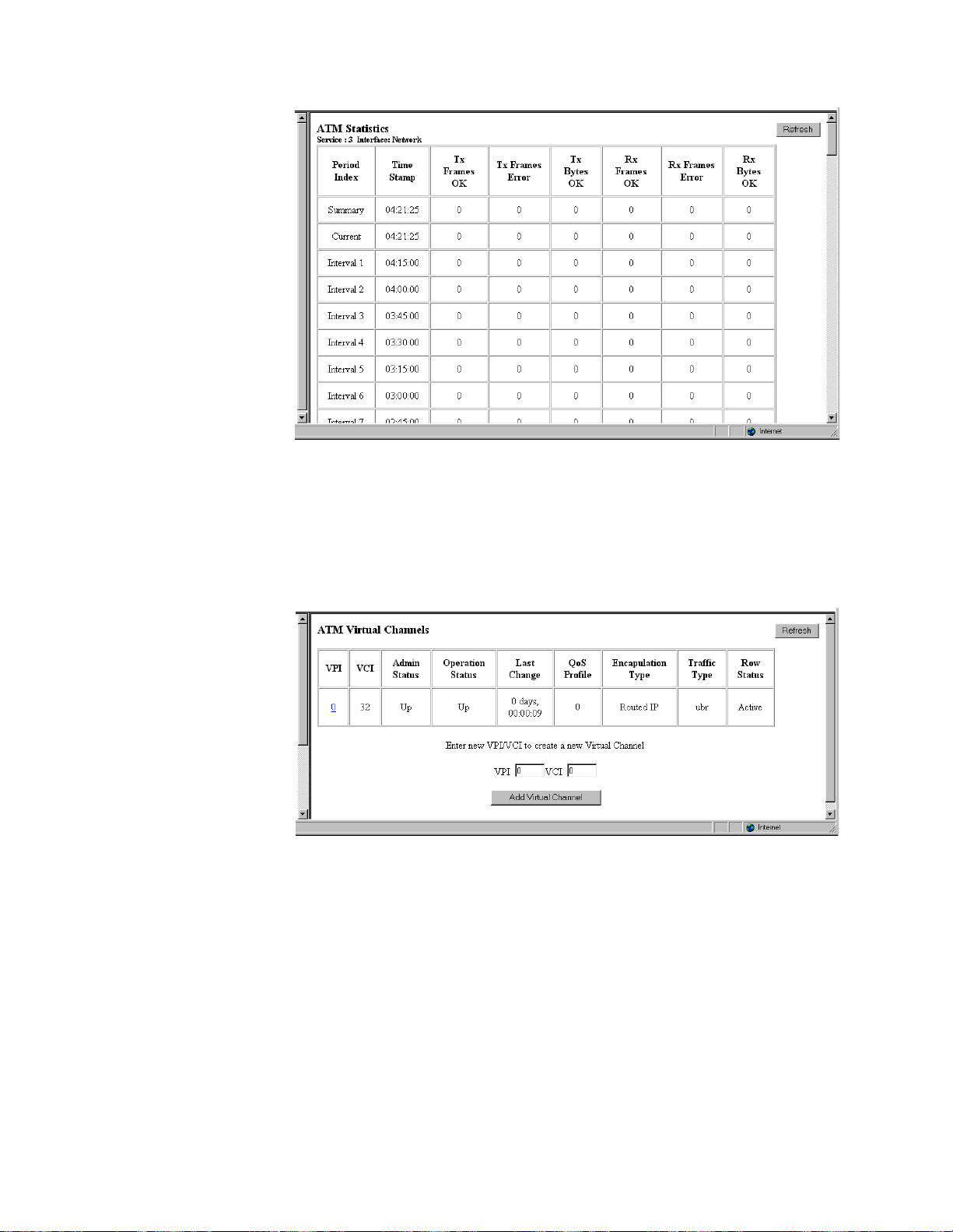
3-32
Figure 3.28
ATM Virtual Channels Screen
Clicking the “Virtual Chan nels” button on the ATM Serv ice Details sc reen
will display a table (Figure 3.29) of all Virtual Channels on a specific ATM
service along with their state and alarm conditions.
The ATM Virtu al Channels scr een displays status infor mation on the
following parameters listed below. The QoS Profile and Admin Status are
configured or changed on the Virtual Channel Details screen (
Figure 3.30).
VPI
Virtual Pat h Identifi er numbe r.
VCI
Virtual Channel Identifier number.
Adm in Status
Current Admin Status.
Values:
Up, Down, Testing
ATM Statistics (All Intervals) Screen
Figure 3.29
ATM Virtual Channels Screen
WANsuite 6x30
Page 61

3-33
Operation Status
Current Operation Status.
Values:
Up, Down, Testing
Last Change
Time and date of the Last Ch ange.
QOS Profile
Current QOS profile in use. The default profile is 0 (zer o), which is used for
UBR traffic.
When QOS profile “0” is used, the available bandwidth will be equally shared
among all configured channels. QOS “0” cannot be modified.
If one virtual channel requires more bandwidth than others, configure another
QOS profile and set its peak cell rate (PCR) to the required value. However,
the sum of the PCRs of all configured channels must be no greater than the
available bandwidth. The available PCR on a T1-ATM link is about 3600
cells per second, but is about 4550 cells per second on an E1-ATM link.
Encapsulation Type
Encapsulation Type used. Default is Routed IP, which uses RFC 1483 LLC
encapsulation. If Serial PPP is selected, PPP traffic received from the Serial
port will be sent over the ATM port using RFC 1483 PPPoA encapsulation.
There can be only one VCI configured for Serial PPP.
Serial HDLC is similar to Serial PPP except, when you select Serial HDLC,
data is encapsulated transparently. Any type of HDLC traffic will be
supported. Because this is not a standard encapsulation, a WANsuite unit
must reside at each end of the connection. Even if Serial HDLC or Serial PPP
encapsulation is configured, routed IP traffic received on this channel will be
forwarded to the IP Gatewa y, if IP Gateway is configure d.
Values:
Serial PPP, Routed IP, Serial HDLC
Tra ffic Ty p e
Traffic type used. This is a read-only parameter.
Values:
cbr, ubr
Row Status
Current status of the VCC.
Values:
active, notinService, notReady, createAndGo, createAndWait,
destroy
Adding a New Virtual Channel
To create a new virtual chan nel, enter the d esired VPI/V CI values in th e
appropriate fields near the bottom of the screen and click on the “Add Virtual
Channel” button.
If the newl y added virtual channel is within the maxim um VCC paramete r, it
will be activated immediately.
NOTICE:
Click on a listed VPI to brin g up the Vi rtual Chan nel Details screen (
)
where you can view and/or change parameters.
When adding a Virtual Channel,
above, but for VCI, must be 32 and above.
the value for VPI may be 0 and
Figure 3.30
Web Server Interface
Page 62

3-34
Figure 3.30
The following user-activated buttons are included on the Virtual Channel
Details Scre en:
Quality of Service (QoS) Table Screen
Clicking on the “QoS Profiles” button on the ATM Service Details screen will
display the screen shown in
Figure 3.31.
The table displayed on this screen contains information on ATM traffic
descriptor type and the associated parameters.
Param 1 (PCR)
First parameter of the ATM traffic descriptor used.
Service Category
ATM service category. Possible values include CBR and UBR.
Button
Function
Submit
Sets any values that have been changed.
Virtual Channel Statistics
Displays the current Virtual Channel statistics.
Type Details
Returns you to the ATM Service Details screen.
QoS Profiles
Displays configured QOS profiles.
Delete Virtual Channel
Displays a confirmation screen.
Refresh
Refreshes data on the current page.
Virtual Channel Details Screen
Figure 3.31
WANsuite 6x30
ATM Quality of Service Profiles Screen
Page 63

3-35
Row Status
Current status of the VCC.
Clicking on one of the available “Traffic Description Parameters Index”
entries on the ATM Quality of Service Profiles screen will display a screen
similar to the screen shown in Figure 3.32. Use this screen to configure or
change the QoS parameters listed below.
Figure 3.32
Pa r a me ter (P CR)
Peak cell rate to use for all channels using this QOS profile.
Service Category
ATM servic e category.
Values:
CBR, UBR
Default:
UBR
Row Status
Current status of the profile.
HDLC/PPP Service
This servic e has no configura ble param eters.
Applications
The Applications screens describe configuration tables and statistics for
Layer 3 and above that do not map to a specific service or interface.
Service Aware
The Service Aware func tion recog nizes IP tra ffic on the WA N and count s the
number of frames and bytes passed for a specific service based on filters by
VPI/VCI, by IP Add ress, a nd by IP Port. Each ro w of th e Servi ce Awa re tab le
represents a specific set of filter parameters known as a “rule.” Each rule is
established through the Rule Config screen, which is accessed by clicking the
“Rule Detail s” button at th e bottom of t he Service Awa re screen.
The Service Aware screen (Figure 3.33) pr ovides a table showing these
filtered pac ket counts for up to 10 rules. This table indi cates which Se rvice
Aware filters are enabled or disabled, and shows the specific VPI/VCI, IP
ATM Quality of Service Details Screen
Web Server Interface
Page 64

3-36
Address, and IP Port by which the IP traffic is filtered. In addition, this table
shows the Tx Alarm Thresho ld and the cur rent Tx Alarm st atus (if enab led)
for each ru le.
Figure 3.33
The Service A ware screen p rovides the fo llowing user -activated buttons:
Rule Config Screen
Use the Rule Config sc reen (Figure 3.34) to establish Service Aware
parameters. To establish a rule, select the desired rule configuration options,
provide the appropriate filter information where required, and click on the
“Submit” button at the bottom of the screen.
Button
Function
Rule Details
Displays the Rule Configuration screen (page 3-36).
Traffic Meter Stats
Displays the Traffic Meter Statistics screen (page 3-38).
Clear Alarms
Clears all Service Aware alarms.
Refresh
Refreshes data on the current page.
Service Aware Screen
WANsuite 6x30
Page 65

3-37
Figure 3.34
The paragraphs below describe the rule configuration para meters and their
options.
Service
Selects the se rvice to which the rule applie s. Select from a pull-down me nu
that lists ava ilable serv ices.
VPI
Selects the VPI to which the rule applies.
VCI
Selects the VCI to w hich the rule ap plies.
F ilte r By VPI/ V CI
Enables or dis ables filter ing of the IP traf fic in accorda nce with the spec ified
VPI/VCI.
IP Ad d ress
Establishes the IP address by which the rule will filter IP traffic (if enabled).
IP Mask
Represents a range of IP addresses defined so that only machines with IP
addresses within the range defined by the mask are allowed to access an
Internet ser vice. To mask a po rtion of the IP a ddress, repla ce it with the wild
card character “0” (zero). (For example, 192.44.0.0 represents every computer
on the Internet with an IP address beginning with 192.44.)
Filter By IP A d dress
Enables or disables filtering of the IP traffic by the IP address specified in the
IP Address or IP Mask field.
IP P or t
Establishes the IP port by whi ch the rule will filter IP traffi c (if enabled).
Filter B y IP Port
Enables or disables filtering o f the IP traffic by the IP por t specifi ed in the IP
Port field.
Rule Config Screen
NOTICE:
To use this filter, you must specify both the Service and VPI/VCI
parameters in the Rule Config screen.
Web Server Interface
Page 66

3-38
Tx Alarm Threshold
Specifies the threshold (in bps) for the Tran smit Alarm on this rule.
Tx Alarm
Displays the current status of the Transmit Alarm.
Traffic Meter Statistics Screen
The Traffic Meter Statistics screen displays the number of frames and octets
sent over a VPI/VCI that have been counted in accordance with the Service
Aware “rule” that has been established for a Service. A s such, it is
ATM
specific (i.e., VPI/VCIs only occur in
ATM
links). In add ition, this sc reen
provides data rate performance information for the period of time specified in
the Period Index field (see below).
Figure 3.35
The Traffic Meter Statistics screen reports on the following parameters:
•
Tx Frames
•
Tx Octets
•
Rx Frames
•
Rx Octets
•
Rate Peak – the peak data rate for the viewed period (see below)
•
Rate Average – the average data rate for the viewed period (see below)
The Period Index field is used to define the period of time for which the
Traffic Meter statistics will be reported. It represents the 24-hour, 15-minute
buckets index. Selecting a period and then clicking the “Submit” button will
display the t raffic meter st atistics for tha t period. The user-select able options
are listed below.
Summary
Represents the past 24 hours; reports the additive number of frames/octets, the
highest peak encountered for 24 hours, and the average for 24 hours.
Cu rrent
Reports on the current 15-minute interval.
Traffic Meter Statistics Screen
WANsuite 6x30
Page 67

3-39
Interva l 1,
In te r v al 2,...,
Interval 96
Reports on Intervals 1-96, which correspond to the periods completed 15
minutes ago, 30 minutes ago,..., 24 hours ago.
SNMP Details Screen
The SNMP Details screen (Figure 3.36) lets you configure the SNMP
parameters described below. The unit detects and reports T1 (6130) or E1
(6230) network alarms and provides several options for reporting them, one of
which is SNMP traps. When a network alarm occurs, the unit sends a trap
message to as many as eight destinations on your network. The unit will
report each alarm by transmitting an SNMP “trap” to each non-zero Trap IP
address.
Figure 3.36
Read Comm unity
Accepts a character string identifying the group author ized to perform read
operations. The default setting is “Public.”
W rite Com m unity
Accepts a character string identifying the group author ized to perform w rite
operations. The default setting is “Private.”
Trap C om m unity
Accepts a character string, which is included in SNMP traps generated by the
unit. The default setting is “Public.”
Tra p IP Ad d r ess
Accepts the IP address of a network device where alarm reporting traps are to
be sent.
The Diagnostics screen (Figure 3.37) shows the Serial and Network interfaces
and whether or not either of them is undergoing a Loop test. Click on the
“Test Details” button at the bottom of the screen to reach a screen (Figure
3.38) where you can select the type of test to be run (PLB, LLB, MLB, Far
PLB, Far LLB).
SNMP Details Screen
Diagnostics Screen (6130 and 6230 Only)
Web Server Interface
Page 68

3-40
Figure 3.37
Trap Log Screen
A trap is a mechanism that permits a device to send an alarm for certain
network events to an SNMP management station. The Trap Log screen
(Figure 3.39) show s all generated traps.
The table shown in this screen lists each trap by its Index number, and
displays the type of error captured by the trap (Trap Number) and the date
and time that th e trap was stor ed (Time Stam p).
Click the “Refresh” button at the top of the screen to display the latest trap
information in the table. To remove all trap information stored in memory,
click the “Delete A ll Traps” button .
Diagnostics Screen
Figure 3.38
Figure 3.39
Test Details Screen
Trap Log Screen
WANsuite 6x30
Page 69

3-41
Top Talkers (Top N Details Screen)
Clicking on the “Top Talkers” link in the navigation tree displays the Top N
Details screen (Figure 3.40), which is used to set the parameters for and
initiate the generation of a list of IP addresses ranked in terms of the number
of frames and octets they have transmitted during a specified reporting period.
(The “N” in “Top N Details” represents the variable number of Top Talkers
that will be reported.) This report allows MIS managers to determine who is
generating the most traffic on a WAN based on IP addresses.
Figure 3.40
To generate a Top Talkers report, enter the desired report size in the
appropriate field, and then click the “Submit” button.
Duration
Establishes the amount of time (in seconds) for which the Top Talkers report
will capture IP tr affic; typically this value is 900 seconds (15 minutes).
Time Remaining
Establishes the amount of time (in seconds) for which the Top Talkers report
will capture IP tr affic; typically this value is 900 (15 minutes). As soon as
you initiate generation of the report by pressing the “Submit” button, the
Duration value is copied over to the Time Remaining field. Click on the
“Refresh” button to see how much time remains before the report is
completed.
Requested Report Size
Establishes how many IP addresses will be reported as the “Top Talkers.”
As soon as the specified Duration for the report has elapsed, the screen will
refresh itself and the resulting report-specific information will be displayed in
the outlined box at the bottom of the screen. This report comprises elements
as defined in the following paragraphs.
Report #
This field displays a unique number used to identify the generated report. This
number is generated automati cally, is incremen ted seque ntially f or each
report, and can be used by management stations for automatic polling (via the
ipadv2.mib).
Top N Details Screen
NOTICE:
While you may request any number, the unit is internal ly limited to a
maximum of 20.
Web Server Interface
Page 70

3-42
WANsuite 6x30
Size
Displays the actual numbe r of IP addresse s identified as Top Talkers in the
generated report. The maximum report size is 20.
Start Time
Displays the time at which the Top Talkers rep ort was initiat ed (based on
System Up Time).
System Up Time
Displays the amount of time that the unit has been operational since it was
turned on or last reset.
The Top Talkers table reports in descending order the IP addresses that have
generated the most traffic during the requested report’s duration. For each IP
address lis ted, the repor t displays th e number of Rx frames, Rx octe ts, Tx
frames, and Tx octets that h ave been passe d across it. In addition, th e
Timestamp field indicates the time at which a packet was examined for the
specified IP address.
IP Gateway Screen
The IP Gateway is a feature that allows routing of IP packets from one
network to another using
static route s
configuration and/or
dynamic routing
.
The IP Gateway uses Routing Information Protocol (RIP) 1 or RIP 2 or Open
Shortest Path First (OSPF) routing.
RIP 1 and RIP 2 are protocols that allow exchange of routing information
between two routers. With that information exchange, a router can build its
own routing tables that later can be used for “routing” IP packets.
OSPF is a shortest path first (SPF) or link-state protocol. OSPF is also an
internal gateway protocol (IGP) that distributes routing information between
routers in a single autonomous system (AS). OSPF chooses the least cost path
as the be st path.
While RIP is ideal for small- to medium-sized networks, OSPF is more
suitable for complex networks with a large number of routers. OSPF provides
equal cost multipath routing where packets to a single destination can be sent
via more than one interface simultaneously.
Page 71

3-43
Figure 3.41
RIP Enable
Globally enables RIP 1, RIP 2, or No RIP.
Values:
Disable, Enable RIP1, Enable RIP2
Default:
Enable (RIP 2)
RIP Trust Neighbors
Globally enables the trusted neighbors feature. If there is a list of trusted
neighbors in an IP Gateway, only RIP packets coming from those trusted
neighbors will be used to build the internal routing table.
Values:
Enable, Disable
Default:
Enable
RIP Interval
Interval for RIP packet to be sent. Default is 30 seconds.
RIP Domain
Value representing the RIP domain. Default is 0.
OSPF Enable
OSPF stands for Open Shortest Path First Rout ing, which is a shortest-path-
first (SPF) or link-state protocol. OSPF is an interior gateway protocol that
distributes routing information between routers in a single autonomous
system. This Protocol is suitable for complex networks with a large number of
routers. If a large network is involved, OSPF may be the solution for the user.
Values:
Disable, Enable
Default:
Disable
OSPF Router ID
This 32-bit number assigned to each router running the OSPF protocol
uniquely ide ntifies the rou ter within an au tonomous s ystem. Each ro uter
requires a uni que router ID. Default is the LAN IP address o f the unit.
IP Gateway Screen
RIP Parameter s
OSPF Parameters
Web Server Interface
Page 72

3-44
The IP Gateway screen provides the following user-activated buttons:
Circuits Screen
Access this menu by clicking on the “Circuit Table” button at the bottom of the
IP Gateway menu. This screen s hows the conf igured ci rcuit. To c onfigure a new
circuit, click on "Add New."
Figure 3.42
Circuit Details Screen
Clicking on the “Circuit Details” button on the Circuits screen will display a
screen similar to the fo llowin g (Fig ure 3.43). This sc re en is used t o esta bli sh th e
configuration parameters of a given circuit. To establish a new circuit or to
change the parameters of an existing circuit, enter the desired values in the
available parameter fields and press the “Submit” button.
Button
Function
RIP Parameters
Static Routes Table
Displays static routes and dynamic routes information.
Static ARP Table
Displays static ARP information.
Trusted Neighbors
Displays trusted neighbors information.
OSPF Parameters
Area Table
Displays area information.
Virtual Link Table
Displays virtual link information.
Submit
Submits to the unit information specific to IP Gateway.
Circuit Table
Lets you access to circuit-related information/operation.
Refresh
Refreshes data on the current page.
Circuits Screen
NOTICE:
WANsuite 6x30
A “Submit” on this screen will activate a newly created circuit. It is not
necessary to perform a “Save and Restart” for the circuit to take effect.
Page 73

3-45
Figure 3.43
Endpoint
Endpoint name. By default, the first circuit is always the LAN circuit. WAN
circuit endpoint names are taken from the VPI/VCI number. For example,
VPI 0/VCI 32 will have “P0-C32” for an endpoint name. The pull-down
menu will display a list of VPI/VCIs actually configured. A given circuit will
receive/transmit data on the VPI/VCI combination corresponding to its
endpoint name.
IP Ad d ress
IP Address of the circuit.
IP Mask
IP mask of the c ircuit.
Ma x Tr a n smit U n it
Maximum trans mit unit this ci rcuit will send at any one time.
Cost
Represents the relative time of treatment of an IP packet. This value is used
when there ar e multiple rou tes to the same de stination. W hen two or more
routes are available, the one with the lowest circuit cost is selected. An ATM
circuit should have a higher value than a LAN circuit.
RIP Status
Indicates whether or not RIP is enabled on this circuit.
Values:
Enable, Disable
Default:
Enable
Multic a st S t a tu s
Indicates whether or not Multicast is enabled on this ci rcuit.
Values:
Enable, Disable
Default:
Enable
Circuit Details Screen
Web Server Interface
Page 74

3-46
WANsuite 6x30
OSP F Status
Indicates whether or not OSPF is enabled on this circuit.
Values:
Enable, Disable
Default:
Disable
OSPF Area
Represents the area that this circuit is part of.
OSPF LSA Timer
Determines how often the Link State Acknowledgment (LSA) packet is sent.
Values:
1−3600
Default:
5
OSPF LSU D elay
The estimated number of seconds it takes to transmit a Link State Update
(LSU) packet over this circuit interface.
Values:
1−3600
Default:
1
OSPF Router Priority
This 8-bit unsigned integer ranges from 1 to 255 and assigns priority to one of
two routers attached to the same network; without an assigned priority, both
routers attempt to become the designated router.
Values:
1−255
Default:
1
OSPF Hello Interval
The time in seconds between the Hello packets that a router sends on a
circuit. This value is also advertised in the router’s Hello packets and must be
identical for all routers on the same network. The smaller the Hello Interval,
the sooner topological changes are detected (but then more traffic is created).
Values:
1−65535
Default:
10
OSP F D ead Interval
The number of seconds that a router’s Hello’s have not been received before
its neighbors declare the router down. The value must be the same as the
value on the network.
Values:
1−65535
Default:
40
OSPF Auth Key
When configured, this parameter allows an authentication procedure to be
executed on th e OSPF header . If the 64-bi t (8 character) password doe s not
correspond, the packet is thrown away.
Values:
64 bits (8 characters)
Default:
8 spaces (no authentication)
The Circuit Details screen provides the following user-activated buttons:
Button
Function
Submit
Sets any values that have been changed.
Circuit Table
Returns you to the previous screen.
Refresh
Refreshes data on the current page.
Page 75

3-47
Static Routes Screen
Under some circumstances, it may not be necessary for a router to learn a
route using ordinary means such as RIP or OSPF. It is possible under these
circumstances for you to add a route to the route table of a router.
The Static Routes menu is always associated with a circuit.
Access this menu by
selecting the Static Routes Table from the RIP Parameters Table on the IP
Gateway menu.
Figure 3.44
Endpoint
Endpoint name (or interface) through which to send the IP packet to reach the
Target IP Address. By default, the first circuit is always the LAN circuit.
WAN circuit endpoint names are taken from the VPI/VCI number. For
example, VPI 0/VCI 32 will have “P0-C32” for an endpoint name. The pull-
down menu will display a list of VPI/VCIs actually confirmed. A given
circuit will receive/transmit data on the VPI/VCI combination corresponding
to its endpoint name.
Target IP A d dress
Represents the target network that you want this router to reach.
Target IP Ma sk
Mask of the target network.
Next Hop
IP address of the next device in the route.
Cost
Cost of using that route.
Route Status
Indicates whether a route is enabled or disabled.
The Static Routes Table screen provides the following user-activated buttons:
Button
Function
Route Details
Displays the static route parameters.
Dynamic Route Table
Displays routes learned via RIP or OSPF.
Add New
Adds a new static route.
Refresh
Refreshes data on the current page.
Static Routes Screen
Web Server Interface
Page 76
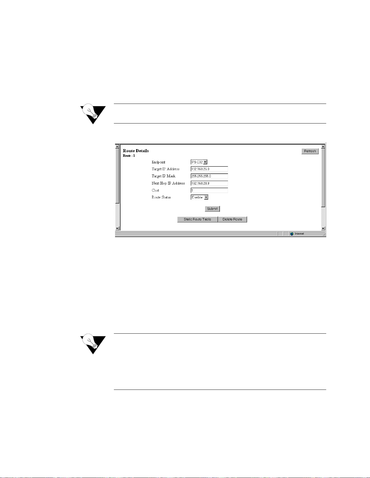
3-48
Route Details Screen
Clicking on the “Route Deta il s” butt on f rom the Static Route menu will di spl ay
the screen s hown in Figure 3.45. This screen is used to establish the
configuration parameters of a given route.
To establish a new route or to change the parameters of an existing route,
enter the desired values in the available parameter fields and press the
“Submit” button.
NOTICE:
Endpoint
Endpoint name (or interface) through which to send the IP packet to reach the
Target IP Address.
Target IP A d dress
Represents the target network that you want this router to reach.
Values:
0.0.0.0
255.255.255.255
Default:
0.0.0.0
Target IP Ma sk
Mask of the target network.
Values:
0.0.0.0
255.255.255.255
Default:
0.0.0.0
the
the
N ext H o p IP A dd ress:
IP address of the next device in the route.
A “Submit” on this screen will activate a newly created route. It is not
necessary to perform a “Save and Restart” for the route to take effect.
Figure 3.45
Route Details Screen
−
−
NOTICE:
WANsuite 6x30
Setting the Target IP Address and Targ et IP Mask to 0.0.0.0 def ines
default route for this unit. Because a unit can have only one default
route, if a default route is configured as a WAN route on the above
screen, the Gateway address configured on the 10/100 Ethernet screen
must be left blank. Likewise, if a Gateway is configured on the 10/100
Ethernet screen, it becomes
can be configured on a Static Route.
default route, and no WAN default route
Page 77

3-49
Cost
Cost of using that route.
Values:
0−65535
Default:
1
Route Status
Indicates whether or not the current route is enabled.
Values:
Enable, Disable
Default:
Enable
The Route Details screen provides the following user-activated buttons:
Dynamic Route Table Screen
Access this menu by c licking on “Dyna mic Rout e Table ” on the St atic Rout es
menu. This table shows both dynamic and static routes. Please note that not
all parameters are necessarily defined, depending on whether or not the routes
were learned dynamically. Primarily, the most useful information is included
in "Destination," "Interface Index," and "Mask" columns.
Figure 3.46
D e st in a tio n
Network to be reached.
If Nd x
Interface internal number.
Next Hop
IP address used to reach the destination network.
Typ e
Direct or Indirect.
Protocols
Local
Age
0
Button
Function
Submit
Sets any values that have been changed.
Static Route Table
Returns you to the previous screen.
Delete Route
Deletes the route currently displayed.
Refresh
Refreshes data on the current page.
Dynamic Route Table Screen
Web Server Interface
Page 78

3-50
Mask
Mask of the destination network.
Static ARP Table Screen
ARP (Address Resolution Protocol) is used by the router to dynamically
associate a high-level IP address to a low-level physical hardware address.
ARP packets are only sent across a single physical network.
There are some cases when an IP-compatible device does not support ARP or
ARP is delibe rately disa bled (for secur ity). In these cases, instead of using
ARP to dynamically update the router internal MAC <-> IP Address Table,
this menu can
force
an entry into that table. This entry never times out.
At least one circuit must be defined to create a Static ARP Table entry
because an ARP entry is always associated with a circuit.
The static ARP table is useful when a Host does not respond to an ARP
request.Access this menu by selecting “Static ARP Table” from the RIP
Parameters screen on the IP Gateway menu.
Endpoint
Endpoint name (or Interface) through which to send the IP packet to reach the
defined IP Address. The default is the LAN.
IP Ad d ress
The IP address of the unit for which you want to define the MAC address.
MAC Address
The MAC address of the host to be reached.
AR P Status
Displays whether this static ARP entry is enabled or disabled.
The Static ARP Table sc reen provides the following user-activated buttons:
Button
Function
ARP Details
Displays details of ARP tables.
Dynamic ARP Table
Displays the dynamically learned MAC <-> IP address.
Add New
Adds a new static ARP.
Refresh
Refreshes data on the current page.
Figure 3.47
ARP Table Screen
WANsuite 6x30
Page 79
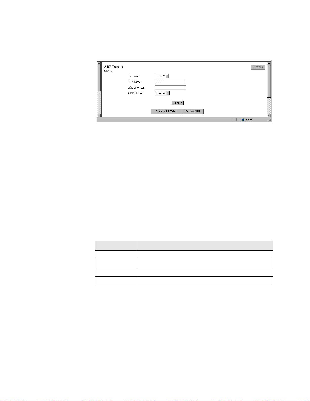
3-51
ARP Details Screen
Access this screen by clicking on the ARP Details button on the ARP Table
screen.
Figure 3.48
Endpoint
Endpoint name (or Interface) through which to send the IP packet to reach the
defined IP Address. Currently, this is always the LAN.
IP Ad d ress
IP address of th e circuit.
Values:
0.0.0.0
255.255.255.255
Default:
0.0.0.0
MAC Address
MAC address of the Host to be reached.
Values:
A 6-byte value
Default:
00-00-00-00-00-00
AR P Status
Displays whether this ARP is enabled or disabled.
Values:
Enable, Disable
Default:
Enable
The ARP Details screen provides the foll owing user-activated buttons:
Trusted Neighbors Screen
The Trusted Neighbors feature can be used to store RIP information only
from specific routers. This allows the router to reject any RIP information
coming from non-Trusted Neighbors. Only information coming from Trusted
Neighbors is kept by the router.
Access this menu by selecting Trusted Neighbors from the RIP Parameters on
the IP Gateway menu. This table is useful when the Network Administrator
wants to lis t en to RIP of specific router(s).
Button
Function
Submit
Sets any values that have been changed.
Static ARP Table
Returns you to the previous screen.
Delete ARP
Deletes this static ARP.
Refresh
Refreshes data on the current page.
ARP Details Screen
−
Web Server Interface
Page 80

3-52
Figure 3.49
The Trusted Neighbors screen provides the following user-activated buttons:
Area Table Screen
An Area allows growth and makes the networks at a site easier to manage. An
area is self-contained; knowledge of an area’s topology remains hidden from
other areas. Thus, multiple groups within a given site retain the ability to
change their internal network topology independently.
Access the Area Table screen from the OSPF Parameters table on the IP
Gateway screen.
ID
Displays the ID of the Area (represented by an IP address).
Enable
Displays whether the defined Area is enabled or disabled.
Auth Type
Indicates Area validation.
Stub
Displays whether or not the defined area is a Stub Area.
Address Sum m ary
Displays the Address Summary of the defined Area.
Button
Function
Neighbor Details
Displays the Trusted Neighbors IP address.
Add New
Adds a Trusted Neighbors IP Address.
Refresh
Refreshes data on the current page.
Trusted Neighbors Screen
Figure 3.50
Area Table Screen
WANsuite 6x30
Page 81

3-53
Mask Summary
Displays the Mask Summary of the defined Area.
Advertise
Displays whether advertising is enabled or disabled for this Area.
The Area Table screen provides the following user-activated buttons:
Area Details Screen
Access this screen by clicking on the Area Details button on the Area Table
screen.
Figure 3.51
Area ID
This paramete r has the same for mat as the IP Add ress of the Mask Ad dress.
Values:
0.0.0.0
255.255.255.255
Default:
0.0.0.0
Enable
Displays whether or not this Area is enabled.
Values:
Enable, Disable
Default:
Enable
Auth Type
Indicates type of Authentication.
Values:
Simple, None
Default:
None
Stub
An area can be configured as stub when there is a single exit point from the
area, or when the choice of exit point need not be made on a per-external-
destination basis.
Values:
Yes, No
Default:
No
Button
Function
Area Details
Displays all parameters associated with the defined Area.
Add New
Defines a new Area.
Refresh
Refreshes data on the current page.
Area Details Screen
−
Web Server Interface
Page 82

3-54
Address Sum m ary
A configured address range specifies what addresses are contained within an
area. When summariz ing the routes in an area t o inform other ar eas, all r outes
falling within the configured range ar e described by a single LSA, thus
decreasing the size of the LSA database.
Values:
0.0.0.0
−
255.255.255.255
Default:
0.0.0.0
Mask Summary
IP Mask of the summary to be added.
Values:
0.0.0.0
255.255.255.255
Default:
0.0.0.0
Advertise
Describes the local state of a router or network. This includes the state of the
route’s interfaces and adjacencies. Each link state advertisement is flooded
throughout the routing domain. The collected link state advertisements of all
routers and networks form the protocol's topological data base.
Values:
Yes, No
Default:
No
The Area Details screen provides the following user-activated buttons:
Virtual Link Table Screen
To permit maximum flexibility, OSPF allows the configuration of
links
to enable the backbone area to appear contiguous despite the physical reality.
In OSPF, the backbone is defined as an A rea ID of 0.0.0.0. This backbone
cannot be disconnected in any way or some areas of the Autonomous System
become unreachable. This is because all inter-area traffic must go through the
backbone. In fact, the backbone is responsible of all inter-area routing
information distribution.
It is possible that an area cannot be connected directly to the backbone; in this
case a virtual link is used (see Figure 3.52). To establish or maintain the
connectivity of the backbone, virtual links can be configured through non-
backbone areas. Basically, virtual links are used to connect components that
are otherwise not connected to the backbone.
A virtual link is treated by OSPF as a point-to-point unnumbered network
joining two area border routers. The virtual link must be configured in both of
the area border routers.
A virtual link is defined by the following two parameters:
Button
Function
Submit
Sets any values that have been changed.
Area Table
Returns you to the previous screen.
Delete Area
Deletes the currently defined Area.
Refresh
Refreshes data on the current page.
−
virtual
WANsuite 6x30
Page 83

3-55
•
The Router ID of the virtual link’s other endpoint
•
The non-backbone area across which the virtual link goes through.
Access this sc reen by sele cting the Virtual Link Table from the OSP F
Parameters table on the IP Gateway screen.
Figure 3.52
Enable
Enables this definition o f a virtual link .
Transmit A rea ID
The non-backbone area that the virtual link goes through.
Area B order R outer ID
The Router ID of the virtual link’s other endpoint.
The Virtual Link Table screen provides the following user-activated buttons:
Virtual Link Details Screen
Access this screen by clicking on the Virtual Link Details button on the Virtual
Link Table screen.
Button
Function
Virtual Link Details
Displays details regarding the selected Virtual Link.
Add New
Defines a new Virtual Link.
Refresh
Refreshes data on the current page.
Virtual Link Table Screen
Figure 3.53
Virtual Link Details Screen
Web Server Interface
Page 84

3-56
The Virtual Link Details screen provides the following user-activated buttons:
Network Address Translation (NAT)
NAT is a method of connecting multiple computers to the Internet (or any
other IP network) using one IP address. This lets users cost-effectively and
efficiently connect their networks to the Internet.
Whether on a global or local port, NAT provides translation only upon receipt
of a packet, which NAT will translate, not translate, or filter, depending on
the user-s pecified p arameter s (further describe d below) . If the d ecision is
made to “translate,” the packet will be modified internally, and eventually
sent on to the IP Gateway to be processed. If the decision is made not to
“translate,” the packet will not be modified in any way. If the decision is
made to “filter,” the packet will be discarded without any further action
required.
NOTICE:
NAT Details Screen
The NAT Details screen (Figure 3.54) lets the user configure the NAT global
parameters described below.
Enable
Enables or disable s NAT. D efault is “ Disable .”
Button
Function
Submit
Sets any values that have been changed.
Virtual Link Table
Returns you to the previous screen.
Delete Virtual Link
Deletes currently defined Virtual Link.
Refresh
Refreshes data on the current page.
You must Save and Restart for any changes in NAT configuration
parameters to take effect.
WANsuite 6x30
Figure 3.54
NAT Details Screen
Page 85

3-57
Mode
Selects th e Networ k Addres s Port Tr anslation (NAPT) mode or the Basi c
NAT mode. In NAPT mode, all hosts on the Global (public) side view all
hosts on the Local (private) side as a single internet host (one IP address). In
Basic NAT mode, the Global IP address is assigned as a Class C host address
(Mask of 255.255.255.0). Each private IP address on the Local side is mapped
to a Class C public address on the Global side. In other words, if there are 30
hosts on the private (Local) side, 30 public (Global) addresses are required.
The default is NAPT.
Global IP A ddr
Global IP Address used in NAPT mode. Must be a valid Class C address.
Default is LA N IP Address.
Global M ask
IP Mask asso ciated with de fined Global IP Address. D efault is LAN IP Mask.
ICM P D efault Addr
Default source address used to answer any ICMP request. Default is LAN IP
Address. ICMP requests are not transferred from the Global to the Local side.
Rather they are answered by the unit itself since Local addresses are private
and do not receive unsolicited requests.
F ilte r Non L o c a l
Address
Discards any packet with “non corporate” source address. Default is “Enable.”
The screen pa rameters liste d below are rel ated to the NA T Control Block
Timer. Note that default values should be in accordance with most NAT
applications. The timers’ values minimize NAT resources. Generally, when a
timer has expired, the resources used are no longer needed. Those resources
will then be available for other connection resources.
IP E n try T im er
The maximum time (in seconds) NAT will use resources when not using
TCP, UDP, or ICMP.
Values:
0−65535
Default:
120
TCP Connection Tim er
The maximum time (in seconds) NAT will use resources when attempting to
establish a TCP connection.
Values:
0−65535
Default:
300
TC P C losing Timer
The maximum time (in seconds) NAT will use resources when attempting to
close a TCP connection.
Values:
0−65535
Default:
0
TC P Disconnected
Tim er
The maximum time (in seconds) NAT will use resources when attempting to
disconnect from TCP.
Values:
0−65535
Default:
120
Web Server Interface
Page 86

3-58
TCP Sequence Delta
Tim er
The maximum time (in seconds) NAT will use resources when managing TCP
Packet Sequencing.
Values:
0−65535
Default:
180
UDP Timer
The maximum time (in seconds) NAT will use resources for a UDP port in
use.
Values:
0−65535
Default:
120
IC MP T ime r
The maximum time (in seconds) NAT will use resources for any ICMP
request.
Values:
0−65535
Default:
120
The NAT Details screen provides the following user-activated buttons:
Static TCP Translation Table Screen
The Static TCP Translation Table screen allows static mapping of global TCP
Server ports to a local host IP address/port combination. The parameters
described below enable access to TCP servers on the private/corporate
network “behind the NAT.” The parameters may be used only when in NAPT
mode.
Figure 3.55
G lobal Port
Decimal IP Por t exposed to th e global Interne t. Default is 0.
Button
Function
Submit
Sets any values that have been changed.
Static TCP Translation Table
Allows stati c mapping of global TCP Server ports to
a local host IP address/port combination.
Static UDP Translation Table
Allows static mapping of global UDP Server ports to
a local host IP address/port combination.
NAT Port Table
Defines NAT global/Internet and local/corporate
ports.
Refresh
Refreshes data on the current page.
WANsuite 6x30
Static TCP Tr anslation Table Scre en
Page 87

3-59
Server Port
Decimal IP Por t of the local TC P Server. This po rt is usually the same as the
Global Port. Default is 0.
Serv er Add ress
IP Address of the local TCP Server. Default is 0.0.0.0 .
The Static TCP Translation Table screen provides the following user-activated
buttons:
You can configure or change the above-listed parameters on the Static TCP
Translation Details screen (Figure 3.58), which is accessed by selecting the
appropriate number under the Index column on the Static TCP Translation
Table screen.
Figure 3.56
Static UDP Tra nslation Table Screen
The Static UDP Translation Table screen (Figure 3.57) allows static mapping
of global UDP Server ports to a local host IP address/port combination. The
parameters described below enable access to UDP Servers on the private/
corporate network “behind the NAT.” The parameters may be used only when
in NAPT mode.
G lobal Port
Decimal IP Por t exposed to th e global Interne t. Default is 0.
Button
Function
NAT Details
Returns the user to the previous screen.
Add New
Lets the user add additional addresses.
Refresh
Refreshes data on the current page.
Static TCP Tr anslation Details Screen
Figure 3.57
Static UDP Translation Table Screen
Web Server Interface
Page 88

3-60
Server Port
Decimal IP Port of the local UDP Server. T his port is usually th e same as the
Global Port. Default is 0.
Serv er Add ress
IP Address of the local UD P Server. Default is 0.0.0.0 .
The Static UDP Translation Table screen provides the following user-
activated buttons:
You can configure or change the above-listed parameters on the Static UDP
Translation Details screen (Figure 3.58), which is accessed by selecting the
appropriate number under the Index column on the Static UDP Translation
Table screen.
Figure 3.58
NAT Ports Screen
The parameters on the NAT Ports screen (Figure 3.59) define the NAT
global/Internet and local/Corporate ports. These parameters are configured in
the NAT Ports Details screen shown in Figure 3.60. Access the NAT Ports
Details screen by clicking on the Index number of the desired port on the
NAT Ports screen.
Endpoint
The Endpoin t name of the ci rcuit associ ated with th e LAN or WAN po rt.
Default is LA N for the first po rt.
Enable
Enables or disables the NAT port. Default is “Enable.”
Button
Function
NAT Details
Returns the user to the previous screen.
Add New
Lets the user add an additional address.
Refresh
Refreshes data on the current page.
Static UDP Translation Details Screen
Figure 3.59
WANsuite 6x30
NAT Ports Screen
Page 89
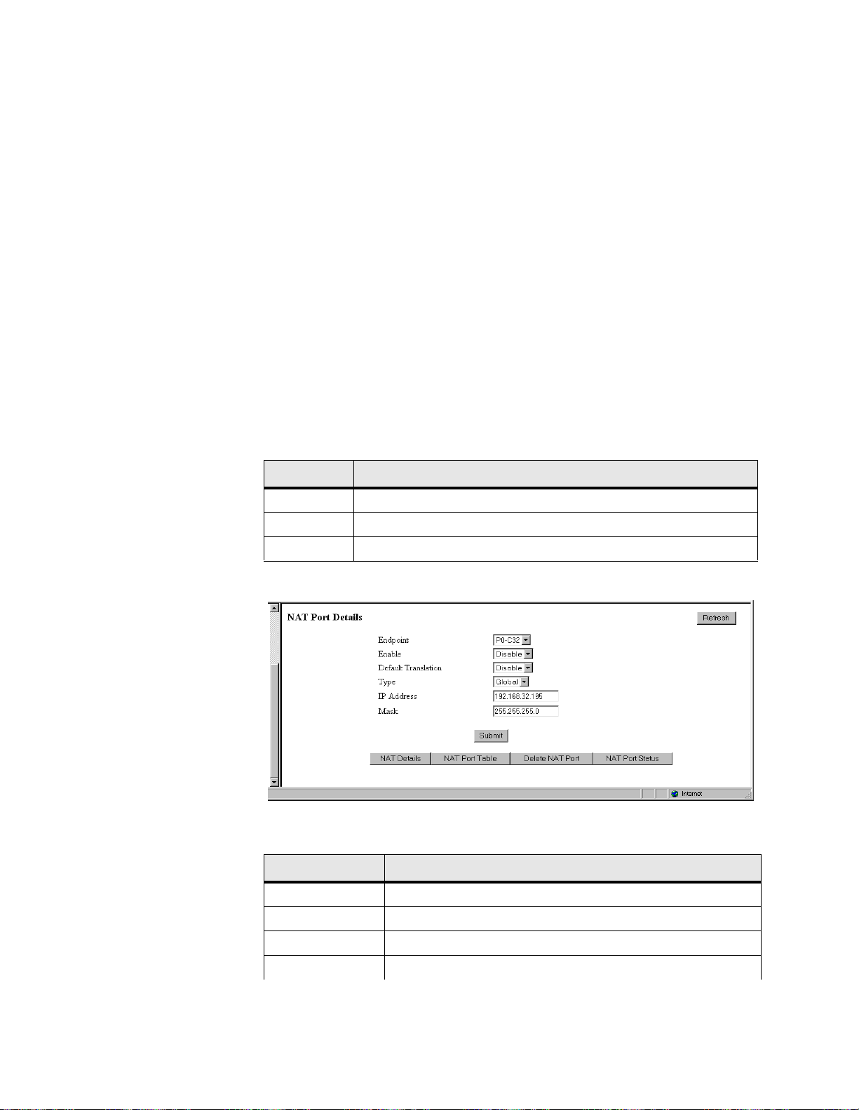
3-61
Default Tran slation
Forces translation on a specific IP port regardless of the source IP Address. If
Default Translation is set to “Enable,” the packet will never be discarded, but
will always pass through the translation path. Therefore, any packets with a
destination address different from the global/Internet network address will be
processed by the IP Gateway, and may be routed to another port. If this
parameter is set to “Disable,” no packet with a destination address different
from the global/Internet address will be processed. Setting this parameter to
“Disable” will override an “Enable” parameter set under “Filter Non Local
Address” on the NAT Details menu.
Typ e
Defines whe ther this por t is local or gl obal. Defau lt is LAN glob al. All othe rs
are local.
IP Ad d ress
IP Address o f this por t. Defau lt is the va lue def ined in th e IP Gate way Circu it
Table.
Mask
Mask related to the defined IP Address. Default is the value defined in the IP
Gateway Circuit Table.
The NAT Ports screen provides the following user-activated buttons:
Figure 3.60
The NAT Port Details screen provides the following user-activated buttons:
Button
Function
NAT Details
Returns the user to the previous screen.
Add New
Lets the user add additional addresses.
Refresh
Refreshes data on the current page.
Button
Function
Submit
Sets any values that have been changed.
NAT Details
Returns the user to the previous screen.
NAT Port Table
Lets the user add additional addresses.
Delete NAT Port
Deletes the specified NAT Port.
NAT Port Details Screen
Web Server Interface
Page 90

3-62
The NAT Port Status Table displays for each port the processed packets from
specific IP addresses.
Figure 3.61
IP Ad d ress
Original IP Address of the host.
NAT IP Address
Translated IP Address of the host.
Proc essed P ack ets
Number of packets processed by NAT for this address.
Dynamic Host Configuration Protocol (DHCP)
DHCP provides a mechanism through which computers using TCP/IP can
obtain protocol configuration parameters automatically through the network.
The most important conf iguration parameter associated with DHCP is the IP
address. A co mputer must in itially be as signed a speci fic IP address th at is
appropriate to the network to which the computer is attached, and that is not
assigned to any other co mputer on tha t network. If a computer moves to a
new network, it must be assigned a new IP address for that new network.
DHCP can be used to manage these assignments automatically.
DHCP has other important configuration parameters also, such as the subnet
mask, default router, and Domain Name System (DNS) server. Using DHCP,
a network administrator can avoid “hands-on” configuration of individual
computers through complex and confusing setup applications. Instead, those
computers can obtain all required configuration parameters automatically,
without manual intervention, from a centrally managed DHCP server. DHCP
is available on the 10/100 Ethernet port only.
NAT Port Status
Displays the NAT Port Status Table screen (
Figure 3.61).
Refresh
Refreshes data on the current page.
Button
Function
NAT Port Status Table Screen
NOTICE:
WANsuite 6x30
You must Save and Restart for any changes in DHCP configuration
parameters to take effect.
Page 91

3-63
DHCP Details Screen
The DHCP Details screen (
Figure 3.62) lets you configure the parameters
described b elow.
Figure 3.62
Enable
Enables or disables the DHCP Server. Default is “Enable.”
Number of Ports
Defines the number of DHCP ports to be used. In this version, only “1” is a
valid value.
TTL
Time to Live for any DHCP packet. Default is 64.
Service Type
Type of Service used by the DHCP Server packet. Default is 1.
Lease Time
Tells the DHCP client the number of seconds it can re tain this IP address. The
client should make a new DHCP request within the specified amount of time
to ensure the IP address is not given to another PC. Default is 600 seconds.
Primary D N S IP A ddr
If requested by DHCP client, the client then uses this address to resolve
names of IP addresses. Default is 0.0.0.0.
Secondary D N S IP
Addr
If requested by DHCP client, the client then uses this secondary address to
resolve names of IP addresses. Defaul t is 0.0.0.0.
Domain Name
Domain name to be used by all DHCP clients. Default is user’s server.
Router IP Addr
IP address that all clients use for Gateway or Router. Default is 0.0.0.0.
The DHCP Details screen provides the follow ing user-activated buttons:
Button
Function
Submit
Sets any values that have been changed.
Host Table
Lists Host names (DHCP server identification).
Static Entry Table
Creates a list of static IP addresses associated with MAC
addresses.
IP Address List Table
Defines the addresses available for DHCP clients.
DHCP Details Screen
Web Server Interface
Page 92

3-64
DHCP Hosts Screen
In some cases , it may be nece ssary to provi de an IP station with a specif ic
DHCP server name, which may be used by the IP station when making a
DHCP request. That name is included on the DHCP Hosts screen (Figure
3.63), which identifies the DHCP server sending DHCP packets. This
parameter is configured on the DHCP Hosts Details screen accessed by
clicking on an “Index” number.
Figure 3.63
Host Name
The name of the DHCP Server. Default is none.
The DHCP Hosts screen provides the following user-activated buttons:
Static Entries Screen
The Static E ntrie s scree n (Fig ure 3. 64) list s stat ic IP a ddress es as sociate d with
MAC addresses. This ensures that the same IP address will always be used for
a given PC provided its MAC address is known. These parameters are
configured on the Static Entries Details screen accessed by selecting a number
from the “Entry Index” column.
IP Address Status Table
Displays DHCP Server statistics.
Refresh
Refreshes data on the current page.
Button
Function
Button
Function
DHCP Details
Returns the user to the previous screen.
Add New
Adds a new Server name.
Refresh
Refreshes data on the current page.
DHCP Hosts Screen
NOTICE:
WANsuite 6x30
You must Save and Restart for the new Server name to become active.
Page 93

3-65
Figure 3.64
MAC Address
MAC Address you want to associate with an IP address.
IP Ad d ress
IP Address given to the DHCP client if that client has the MAC Address
defined on this screen.
Mask
Mask associ ated with the IP Address shown on the sc reen.
Host Name
Name given to the DHCP client.
The Static Entries screen provides the following user-activated buttons:
IP Address List Screen
The IP Address List screen (Figure 3.65) displays the “pool” of addresses
available for DHCP clients. These parameters are configured on the IP
Address List Details screen accessed by clicking on an “Index” number.
Start
Starting IP Address of the DHCP client pool.
End
Ending IP Address of the DHCP client pool.
Subnet Mask
Subnet Mask associated with the defined range.
Button
Function
DHCP Details
Returns the user to the previous screen.
Add New
Lets the user add an additional Static Entry.
Refresh
Refreshes data on the current page.
DHCP Static Entries Screen
Figure 3.65
IP Address List
Web Server Interface
Page 94

3-66
Exclude Start
Beginning of “excluded” range.
Exclude End
End of “excluded” range.
The IP Address List screen provides the following user-activated buttons:
IP Address Status Screen
The IP Address Status screen (Figure 3.66) displays a list of all current DHCP
clients.
Figure 3.66
MAC Address
MAC Address of this DHCP client.
IP Ad d ress
IP Address given to this DHCP client if that client has the MAC Address
defined on this screen.
Status
Provides IP Address Status.
Utilities
The options available under the Utilities branch of the navigation tree serve as
utilities for upgrading your unit’s software, managing access with passwords,
and logging off the system.
Software Upgrade
This screen (Figure 3.67) is used to upgrade the software in your unit. The
revision level for the software that your unit is currently using will be
displayed in the top frame of the Web Server interface. After installing a
software upgrade, the new revision level will be displayed in this frame.
Button
Function
DHCP Details
Returns the user to the previous screen.
Add New
Lets the user add an additional IP address.
Refresh
Refreshes data on the current page.
IP Address Status Screen
WANsuite 6x30
Page 95

3-67
NOTICE:
To upgrade the unit’s software, perform the following steps:
1
Click the “SW Upgrade” link on the navigation tree.
2
Click the “Browse” button to find and select the upgrade file
)
provided by Verilink. After selecting the appropriate file, the filename and
its path will appear in the field next to the “Browse” button. (Alternatively,
you may type the filename and its location directly into this field.)
3
Once the upgrade file has been specified, click the “Install” button. The
message window shown below will appear.
4
After the image is in RAM, the message window will disappear and a
countdown screen (Figure 3.68) will be displayed. When the countdown
reaches 0, the Unit screen s hown in Figu re 3.1
on page 3-3 will be displayed
and will contain the new code.
During the last 2 minutes of the upgrade process, the unit’s memory will
be reprogrammed; the unit will be inoperable during this time.
Figure 3.67
Software Upgrade Screen
(
xxx
.hex
NOTICE:
Make sure you allow sufficient time for the download to occur. If you
cancel the download before it has fully executed, the new software WILL
NOT be installed.
Web Server Interface
Page 96

3-68
Figure 3.68
Password
The Password screen (Figure 3.69) is used to modify the password that
restricts access to the Web Server interface.
Acceptable characters fo r use in a passw ord are
digits 0–9 and letters A–Z
and a–z, f or a tot al of 62 d istinct characters .
To change the password, you must enter it once in the New Password field
and then re-en ter the same pa ssword in the Confirm Passw ord field. Afte r
entering the new password in both these fields, click the “Change Password”
button to update and establish the new password.
Countdown Screen
Figure 3.69
NOTICE:
Password Screen
Remember that passwords are case-sensitive. When logging on,
password must be en tered exactly as i t was programmed.
WANsuite 6x30
Page 97

3-69
Log Out
The Log Out screen (Figure 3.70) is used to log the current user off of the
Web Server.
Figure 3.70
The Log Out function is only available af ter user password protection has
been set. You will be automatically logged out of the system 1 hour after you
log on using a password to gain access; after this, you will be required to
enter the password to gain write access.
Log Out Screen
Web Server Interface
Page 98

3-70
WANsuite 6x30
Page 99

C
HAPTE
R
4
C
VT100 I
NTERFAC
E
Introduction
Screen Components
4
HAPTER
This chapter describes the menus and options associated with the WANsuite
6x30’s VT100 interface. In cases where all 6x30 VT100 configuration screens
are the same, only the 6130 screens showing various configurations are
displayed. However, where the configuration screens of the units differ, as in
the Network Interface screens and their submenus, each unit’s configuration
screens are displayed. Even when all screens resemble each other, parameter
values and/or defaults may vary from unit to unit; these differences are noted.
You can access the VT100 interface locally via the Supervisory port or
remotely through a TELN ET session. To access the VT 100 screens locally,
verify the Supervisory type is “tty” and the Supervisory port speed matches
the terminal emulation program that’s being used. (Port speeds supported
include the following: 1200, 2400, 4800, 9600, 19200, 38400, 57600, and
115200 bps.) You can access the VT100 interface remotely by opening a
TELNET session, entering the unit’s IP address, and connecting to the unit.
All screens in this chapter were captured during a TELNET session.
The VT100 terminal screens have components common to all screens (see
Figure 4.1 below). These components include the device type (in the example
below, Verilink WANsuite 6130), which is centered on the screen, the
software and hardware revision numbers (upper left), the date and time (upper
right), the menu title (“Main” in the figure below), and the serial number
under which the unit is operating.
Figure 4.1
VT100 Terminal Screen Components
VT100 Interface 4-1
Page 100

Cursor Controls
The VT100 interface uses a blinking cursor to select various menus and then
to select sub-menus and/or fields within those menus. You can navigate using
this cursor in different ways, depending on the program you use. Most
programs allow use of the “Tab” key and the “Shift+Tab” keys. Others allow
use of the arrow keys.
NOTICE:
If you are not able to use your arrow keys, access the pull-down
menu under “Terminal,” click on “Preferences,” and be sure the
“VT100 Arrows” box is checked.
For keyboards that do not have these standard keys or have only some of
them, an alt ernativ e set o f curso r cont rol com mands is prov ided. P erfor m each
command by pressing a letter key while holding down the “Ctrl” ke y. You
may use the alternat ive commands and keyboard commands listed below
interchangeably at your discretion.
You can navigate further within a menu as described below.
Field Types
Each menu screen is composed of fields. The two basi c field types are user-
selectable (most of these are in brackets or parentheses) and display-only (no
brackets or parentheses). If you can move the highlighted cursor to a field,
that field is user-selectable; all other fields are display-only. User-selectable
fields are those in which you can make changes or execute commands. To
save changed parameters, in most cases you will “Esc” out of the current
menu after cha nging th e paramet ers. In som e cases, you will pres s the “Ent er”
key to save new parameters.
Fields enclosed in brackets [ ] offer a li st of selections from which to choose.
The selections may be made by pressing your Spacebar to “toggle” between
choices. Each time the Spacebar is pressed, a new item appears. When the
item you wish to choose is displayed, press the “Esc” key to save it.
Fields enclosed in parentheses ( ) are manipulated by one of the following
two methods. The first is to press the “Enter” key to simply execute the
function. The most common type of field in parentheses accepts typed input
in the form of letters and/or numbers. Typing characters when the field is
Keyboard Command
Alternative Command
Left Arrow
Ctrl+S
Right Arrow
Ctrl+D
Up Arrow
Ctrl+E
Down Arrow
Ctrl+X
Backspace
Ctrl+H
Delete
Ctrl+Z
4-2 WANsuite 6x30
 Loading...