

Page 1
e335
1
QZ.
2
ABC
3
DEF
6
MNO
9
WXY
5
JKL
8
TUV
0
X
I
O
#
4
GHI
7
PRS
Cancel
Clear
Enter
”
*
’
,
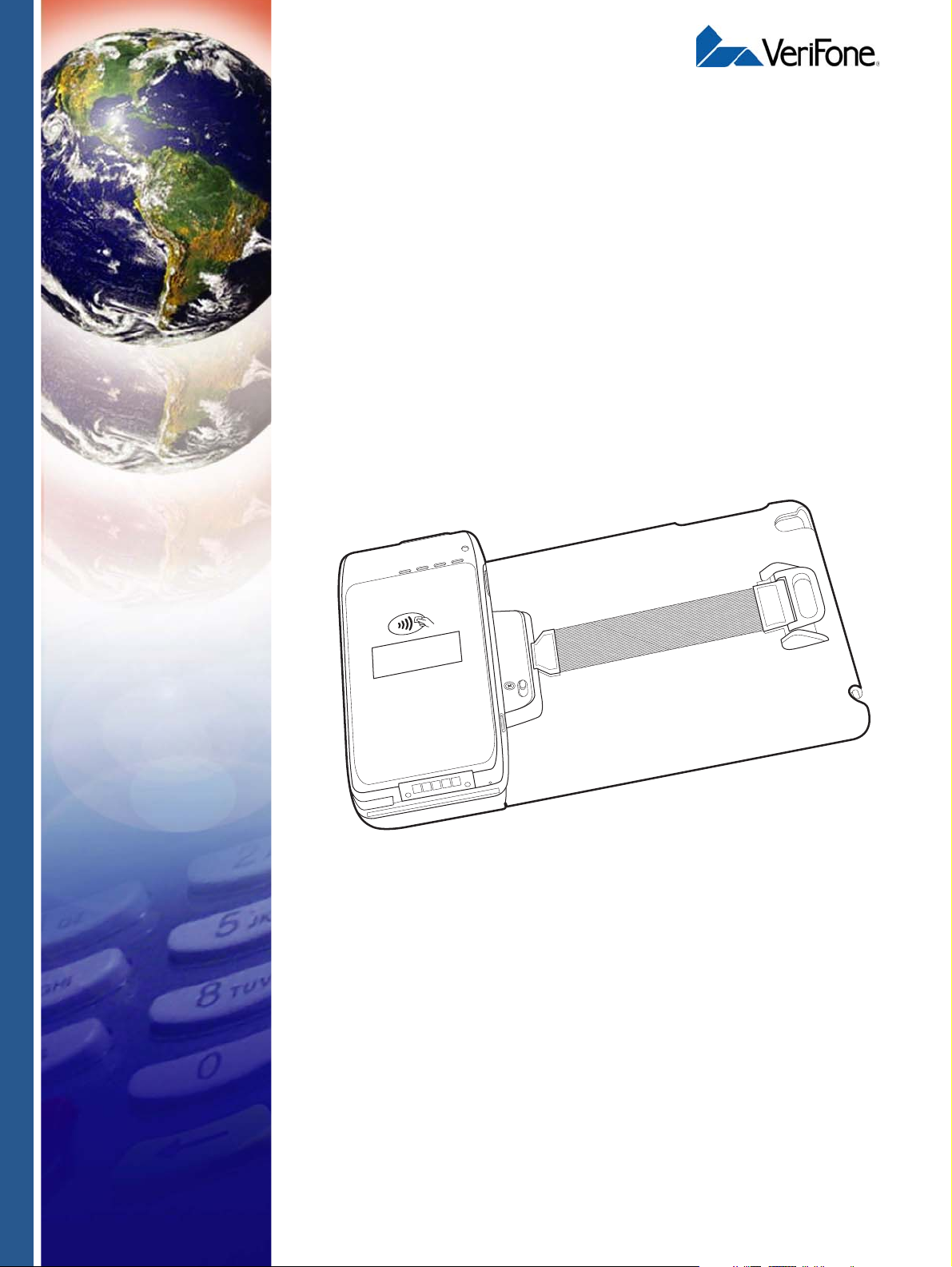
Installation Guide
VeriFone Part Number DOC087-053-EN-A, Revision A
Page 2

e335 Installation Guide
WARNING
© 2013 VeriFone, Inc.
All rights reserved. No part of the contents of this document may be reproduced or transmitted in any form without the written
permission of VeriFone, Inc.
The information contained in this document is subject to change without notice . Although VeriFone has attempted to ensure the
accuracy of the contents of this document, this document may include errors or omissions. The examples and sample programs are
for illustration only and may not be suited for your purpose. You should verify the applicability of any example or sample p rogram
before placing the software into productive use. This document, including without limitation the examples and software programs, is
supplied “As-Is.”
VeriFone, the VeriFone logo, Omni, VeriCentre, and Verix are registered trademarks of VeriFone. Other brand names or trademarks
associated with VeriFone’s products and services are trademarks of VeriFone, Inc.
All other brand names and trademarks appearing in this manual are the property of their respective holders.
Comments? Please e-mail all comments on this document to your local VeriFone Support Team.
The e315 uses an internal lithium-ion rechargea ble battery. Do not dispose the e315 in a fire.
lithium-ion polymer batteries must be recycled or disposed of proper ly. Do not dispose of
lithium-ion polymer batteries in municipal waste sites.
VeriFone, Inc.
2099 Gateway Place, Suite 600
San Jose, CA, 95110 USA
1-800-VERIFONE
www.verifone.com
VeriFone Part Number DOC087-053-EN-A, Revision A
Page 3

CONTENTS
PREFACE . . . . . . . . . . . . . . . . . . . . . . . . . . . . . . . . . . . . . . . 5
Audience. . . . . . . . . . . . . . . . . . . . . . . . . . . . . . . . . . . . . . . . . . . . . . . . . . . . . . . . 5
Organization. . . . . . . . . . . . . . . . . . . . . . . . . . . . . . . . . . . . . . . . . . . . . . . . . . . . . 5
Related Documentation . . . . . . . . . . . . . . . . . . . . . . . . . . . . . . . . . . . . . . . . . . . . 5
Conventions and Acronyms . . . . . . . . . . . . . . . . . . . . . . . . . . . . . . . . . . . . . . . . . 6
CHAPTER 1
Device Overview Features and Benefits . . . . . . . . . . . . . . . . . . . . . . . . . . . . . . . . . . . . . . . . . . . . . 8
Exceptional Ease of Use . . . . . . . . . . . . . . . . . . . . . . . . . . . . . . . . . . . . . . . . . 8
Performance and Durability . . . . . . . . . . . . . . . . . . . . . . . . . . . . . . . . . . . . . . 8
Security. . . . . . . . . . . . . . . . . . . . . . . . . . . . . . . . . . . . . . . . . . . . . . . . . . . . . . 8
Contactless Capability . . . . . . . . . . . . . . . . . . . . . . . . . . . . . . . . . . . . . . . . . . 8
CHAPTER 2
Device Setup Usage Guidelines. . . . . . . . . . . . . . . . . . . . . . . . . . . . . . . . . . . . . . . . . . . . . . . . 10
Environmental Factors . . . . . . . . . . . . . . . . . . . . . . . . . . . . . . . . . . . . . . . . . 10
Personal Security Considerations. . . . . . . . . . . . . . . . . . . . . . . . . . . . . . . . . 10
Electrical Considerations . . . . . . . . . . . . . . . . . . . . . . . . . . . . . . . . . . . . . . . 10
Unpacking the Shipping Carton . . . . . . . . . . . . . . . . . . . . . . . . . . . . . . . . . . . . . 11
Examining Device Features . . . . . . . . . . . . . . . . . . . . . . . . . . . . . . . . . . . . . . . . 12
Front View. . . . . . . . . . . . . . . . . . . . . . . . . . . . . . . . . . . . . . . . . . . . . . . . . . . 12
Back View. . . . . . . . . . . . . . . . . . . . . . . . . . . . . . . . . . . . . . . . . . . . . . . . . . . 12
Installing/Replacing an MSAM Card. . . . . . . . . . . . . . . . . . . . . . . . . . . . . . . . . . 14
Installing/Removing an iPad mini into the e335 . . . . . . . . . . . . . . . . . . . . . . . . . 15
Manually Starting and Shutting Down the e335. . . . . . . . . . . . . . . . . . . . . . . . . 16
Connecting the e335 to a Power Source or a Host Computer. . . . . . . . . . . . . . 16
Using the Gang Charger. . . . . . . . . . . . . . . . . . . . . . . . . . . . . . . . . . . . . . . . . . . 18
Using Multiple Gang Chargers . . . . . . . . . . . . . . . . . . . . . . . . . . . . . . . . . . . 19
Connecting the Gang Charger to a Computer . . . . . . . . . . . . . . . . . . . . . . . 19
Understanding LED Color Behavior. . . . . . . . . . . . . . . . . . . . . . . . . . . . . . . . . . 20
Using a Smart Card to Conduct Transactions . . . . . . . . . . . . . . . . . . . . . . . . . . 20
Using the Magnetic Stripe Reader . . . . . . . . . . . . . . . . . . . . . . . . . . . . . . . . . . . 21
Using the CTLS Reader . . . . . . . . . . . . . . . . . . . . . . . . . . . . . . . . . . . . . . . . . . . 21
Using the Barcode Reader. . . . . . . . . . . . . . . . . . . . . . . . . . . . . . . . . . . . . . . . . 22
CHAPTER 3
Specifications Power . . . . . . . . . . . . . . . . . . . . . . . . . . . . . . . . . . . . . . . . . . . . . . . . . . . . . . . . . 23
Temperature. . . . . . . . . . . . . . . . . . . . . . . . . . . . . . . . . . . . . . . . . . . . . . . . . . . . 23
External Dimensions. . . . . . . . . . . . . . . . . . . . . . . . . . . . . . . . . . . . . . . . . . . . . . 23
Weight . . . . . . . . . . . . . . . . . . . . . . . . . . . . . . . . . . . . . . . . . . . . . . . . . . . . . . . . 23
CHAPTER 4
Maintenance Cleaning the Device . . . . . . . . . . . . . . . . . . . . . . . . . . . . . . . . . . . . . . . . . . . . . . 25
Smart Card Reader . . . . . . . . . . . . . . . . . . . . . . . . . . . . . . . . . . . . . . . . . . . . . . 25
E335 INSTALLATION GUIDE 3
Page 4

CHAPTER 5
VeriFone Service
and Support
Returning a Device for Service. . . . . . . . . . . . . . . . . . . . . . . . . . . . . . . . . . . . . . 27
Accessories and Documentation . . . . . . . . . . . . . . . . . . . . . . . . . . . . . . . . . . . . 28
Accessories. . . . . . . . . . . . . . . . . . . . . . . . . . . . . . . . . . . . . . . . . . . . . . . . . . 28
Documentation . . . . . . . . . . . . . . . . . . . . . . . . . . . . . . . . . . . . . . . . . . . . . . . 28
Battery Pack Instructions . . . . . . . . . . . . . . . . . . . . . . . . . . . . . . . . . . . . . . . . . . 29
CHAPTER 6
Troubleshooting
Guidelines
Device Does Not Start . . . . . . . . . . . . . . . . . . . . . . . . . . . . . . . . . . . . . . . . . . . . 31
Device Display Does Not Show Correct/Readable Info . . . . . . . . . . . . . . . . . . . 31
Blank Display . . . . . . . . . . . . . . . . . . . . . . . . . . . . . . . . . . . . . . . . . . . . . . . . . . . 32
Keypad Does Not Respond . . . . . . . . . . . . . . . . . . . . . . . . . . . . . . . . . . . . . . . . 32
Transactions Fail To Process. . . . . . . . . . . . . . . . . . . . . . . . . . . . . . . . . . . . . . . 32
4 E335 INSTALLATION GUIDE
Page 5

This guide is your primary source of information for setting up the e335.
PREFACE
Audience
Organization
Related
Documentation
This guide is useful for anyone installing a e335 device. Basic descriptions of the
device features are also provided.
This guide is organized as follows:
Chapter 1, Device Overview. Provides an overview of the e335.
Chapter 2, Device Setup. Explains how to set up and install iPad mini into the
e335. It tells you how to select a location, establish power connection, and use
magnetic stripe and barcode readers.
Chapter 3, Specifications. Discusses power requirements and dimensions of the
e335.
Chapter 4, Maintenance. Explains how to maintain your e335.
Chapter 5, V er iFone Service and Sup port. Provides information on how to cont act
your local VeriFone representative or service provider, and information on how to
order accessories or documentation from VeriFone.
Chapter 6, Troubleshooting Guidelines. Provides troubleshooting guidelines,
should you encounter a problem in device installation.
To learn more about the e335, refer to the following set of documents:
e335 Certifications and Regulations VPN DOC087-051-EN-A
e335 Quick Installation Guide VPN DOC087-052-EN-A
e335 Gang Charger Certifications and Regulations VPN DOC087-055-EN-A
e335 Gang Charger Quick Installation Guide VPN DOC087-056-EN-A
e335 Web site
www.paywaremobile.com
E335 INSTALLATION GUIDE 5
Page 6

PREFACE
NOTE
CAUTION
WARNING
Conventions and Acronyms
Conventions and
Acronyms
This section describes the conventions and acronyms used in this guide.
Various conventions are used to help you quickly identify special formatting.
Table 1 describes these conventions and provides examples of their use.
Table 1 Document Conventions
Convention Meaning Example
Blue Text in blue indicates terms that
are cross referenced.
Italics Italic typeface indicates book
titles or emphasis.
Courier The courier type face is used
while specifying onscreen text,
such as text that you would
enter at a command prompt, or
to provide an URL.
The pencil icon is used to
highlight important information.
The caution symbol indicates
possible hardware or software
failure, or loss of data.
See Conventions and Acronyms.
You must install a roll of thermalsensitive paper in the printer.
http://www.verifone.com
RS-232-type devices do not work
with the PIN pad port.
The device is not waterproof or
dustproof, and is intended for
indoor use only.
The lightning symbol is used as
a warning when bodily injury
might occur.
Due to risk of shock do not use the
device near water.
Various acronyms are used in place of the full definition. Table 2 presents
acronyms and their definitions.
Table 2 Acronym Definitions
Acronym Definitions
AC Alternating Current
EMV Europay MasterCard and VISA
LCD Liquid Crystal Display
LED Light Emitting Diode
NFC Near Field Communication
MRA Merchandise Return Authorization
PCI Payment Card Industry
PED PIN Entry Device
PIN Personal Identification Number
USB Universal Serial Bus
VPN VeriFone Part Number
6 E335 INSTALLATION GUIDE
Page 7
Device Overview
1
QZ.
2
ABC
3
DEF
6
MNO
9
WXY
5
JKL
8
TUV
0
X
I
O
#
4
GHI
7
PRS
Cancel
Clear
Enter
”
*
’
,
CHAPTER 1
The e335 integrates the Apple® iPad® mini and VeriFone's PAYware Mobile
technology to create a bold, leading-edge POS solution ide al for consumer-fa cing
and merchant-facing retail integrated applications.
Some of the e335’s key features include: fast processor, large memory, the latest
PCI 3.0 security, integrated 2D laser barcode imager, capacitive-touch encrypted
PIN pad, integrated contactless and NFC-ready. It also features a crisp 128 x 32
display and a spill-resistant capacitive keypad.
Figure 1 The e335 Device
E335 INSTALLATION GUIDE 7
Page 8

DEVICE OVERVIEW
Features and Benefits
Features and
Benefits
Exceptional Ease of
Use
Performance and
Durability
Security
The e335 allows for interaction with customers wherever they may be to assist
them in checking product features, performing sales transactions on the spot, or
confirm pricing with the 2D barcode imager.
• Slim and form fitting to allow seamless integration between the e335 and the
iPad mini.
• The lightweight and ergonomic design allows retailers to easily carry the
device and engage customers anywhere in the store.
• iPad mini touch screen allows for icon-based applications or electronic
signature capture support.
• The Apple Lightning™ connector enables high-speed transaction processing
of all payment types—mag-stripe, NFC/contactless and EMV chip and PIN.
• Standard Micro-USB port allows for convenient product charging, or optional
full-featured gang charging base allows for multiple e335 units to charge at
once.
• Rounded corners to minimize breakage.
• PCI PED 3.x approved for debit and credit card transactions with PIN
Contactless
Capability
• Tamper-resistant construction, SSL protocols, and VeriShield file
authentication
• Supports VeriShield Protect encryption implementations
• Advanced contactless architecture that future-proofs investment with a single
contactless interface, SoftSAMs, and side-by-side application architecture.
• Large tap zone (CTLS logo), that encompasses the PIN pad, optimizes user
experience.
8 E335 INSTALLATION GUIDE
Page 9

Device Setup
CHAPTER 2
This chapter describes the device setup procedure. You will learn about:
• Usage Guidelines
• Unpacking the Shipping Carton
• Examining Device Features
• Installing/Replacing an MSAM Card
• Installing/Removing an iPad mini into the e335
• Manually Starting and Shutting Down the e335
• Connecting the e335 to a Power Source or a Host Computer
• Using the Gang Charger
• Understanding LED Color Behavior
• Using a Smart Card to Conduct Transactions
• Using the Magnetic Stripe Reader
• Using the CTLS Reader
• Using the Barcode Reader
E335 INSTALLATION GUIDE 9
Page 10

DEVICE SETUP
CAUTION
Usage Guidelines
Usage
Guidelines
Environmental
Factors
Personal Security
Considerations
Observe the following guidelines when using your e335.
• Do not use the device where there is high heat, dust, humidity, moisture, or
caustic chemicals or oils.
• Keep the device away from direct sunlight and anything that radiates heat,
such as a stove or motor.
The device is not waterproof or dustproof, and is intended for indoor use only.
Any damage to the unit from exposure to rain or dust may void any warranty.
The e335 is a handover device. Always exercise extreme caution when
conducting transactions especially during PIN entry.
• Hand the e335 directly to the cardholder for PIN entry.
• Encourage the cardholder to hold the e335 close to avoid others to see the
information entered.
Electrical
Considerations
• Avoid using this product during electrical storms.
• Avoid locations near electrical appliances or other devices that cause
excessive voltage fluctuations or emit electrical noise (for example, air
conditioners, electric motors, neon signs, high-frequency or magnetic security
devices, or computer equipment).
• Do not use the device near water or in moist conditions.
10 E335 INSTALLATION GUIDE
Page 11

DEVICE SETUP
CAUTION
NOTE
Unpacking the Shipping Carton
Unpacking the
Shipping Carton
To unpack the
shipping carton
Open the shipping carton and carefully inspect its content s for possible t ampering
or shipping damage. The e335 is a secure product and any tampering may
prevent normal operation.
1 Remove and inspect the following items:
• e335 unit
2 Remove all plastic wrapping from the unit and other components.
3 Remove the clear protective film from the unit.
Do not use a unit that has been damaged or tampered with.
If a label or component appears damaged or if the device appears to have been
opened, please notify the shipping company and your VeriFone representative or
service provider immediately.
4 Save the shipping carton and packing material for future repacking or moving
the device.
Fully charge the e335 device before initial use.
E335 INSTALLATION GUIDE 11
Page 12

DEVICE SETUP
LIGHTNING
ACTION
CONNECTOR
BUTTON
SAM COMPARTMENT
1
QZ.
2
ABC
3
DEF
6
MNO
9
WXY
5
JKL
8
TUV
0
X
I
O
#
4
GHI
7
PRS
Cancel
Clear
Enter
”
*
’
,
CTLS AREA
KEYPAD
MAGNETIC
STRIPE
READER
LCD DISPLAY
SMART
CARD
READER
GANG CHARGER CONTACTS RESET BUTTON
KICKSTAND
HANDSTRAP
LEDS 2D BARCODE LASER IMAGER
MICRO-USB
PORT
Examining Device Features
Examining
Device Features
Front View
Before you continue the installation process, familiarize yourself with the features
of the e335. (See
Figure 2 and Figure 3)
The front panel includes the following features:
Back View
12 E335 INSTALLATION GUIDE
Figure 2 e335 Front Panel
• Lightning connector to connect to an iPad mini.
• Action buttons to activate the 2D imager for scanning barcodes.
• An MSAM (Micromodule-Size Security Access Module) compartment, to
support stored-value card programs or other merchant card requirements.
The back panel includes the following features:
Figure 3 e335 Back Panel
Page 13

DEVICE SETUP
CAUTION
Examining Device Features
• A 128 x 32 pixel monochrome LCD display
• Two types of keys on the capacitive touch keypad:
a A 12-key keypad
b Three color-coded function keys below the keypad
Do NOT paste anything on the keypad surface to avoid malfunction.
• A 2D laser barcode imager located on top of the device for scanning
barcodes
• LEDs that act as CTLS activity, system power, and charging indicators
(See Understanding LED Color Behavior)
• A smart card reader to process smart card transactions
(See Using a Smart Card to Conduct Transactions)
• A CTLS functionality for contactless payments
(See Using the CTLS Reader)
• Gang charger contacts for communication and also for charging the e335
and iPad mini using the e335 gang charger (M087-Q04-50-NAA). See
the Gang Charger.
Using
• A magnetic stripe reader, for performing debit or credit card transactions
(See
Using the Magnetic Stripe Reader).
• A Micro-USB port for data connection and power charging. You can also use
this to connect the e335 to a computer using a standard USB to Micro-USB
cable. (VPN CBL000-021-01-A).
• A kickstand that allows for hands free activities such as typing and viewing.
You can also use the kickstand to stabilize the e335 when placed on a table or
countertop during charging or when connected to a computer.
To use the kickstand, hook your finger under the latch and then pull the stand
inwards, all the way towards the keypad.
• A hand strap that allows you to conveniently hold the e335 and to prevent
dropping of the device.
To use the hand strap, place your hand under the strap and firmly hold the
e335.
E335 INSTALLATION GUIDE 13
Page 14
DEVICE SETUP
CAUTION
NOTE
NOTE
A
B C
D
Installing/Replacing an MSAM Card
Installing/
Replacing an
MSAM Card
To install/replace
MSAM
When you first receive your e335, you may need to install an MSAM card or you
may need to replace an old card.
Observe standard precautions when handling electrostatically sensitive devices.
Electrostatic discharges can damage this equipment. VeriFone recommends
using a grounded anti-static wrist strap.
Not all applications require the use of an MSAM card.
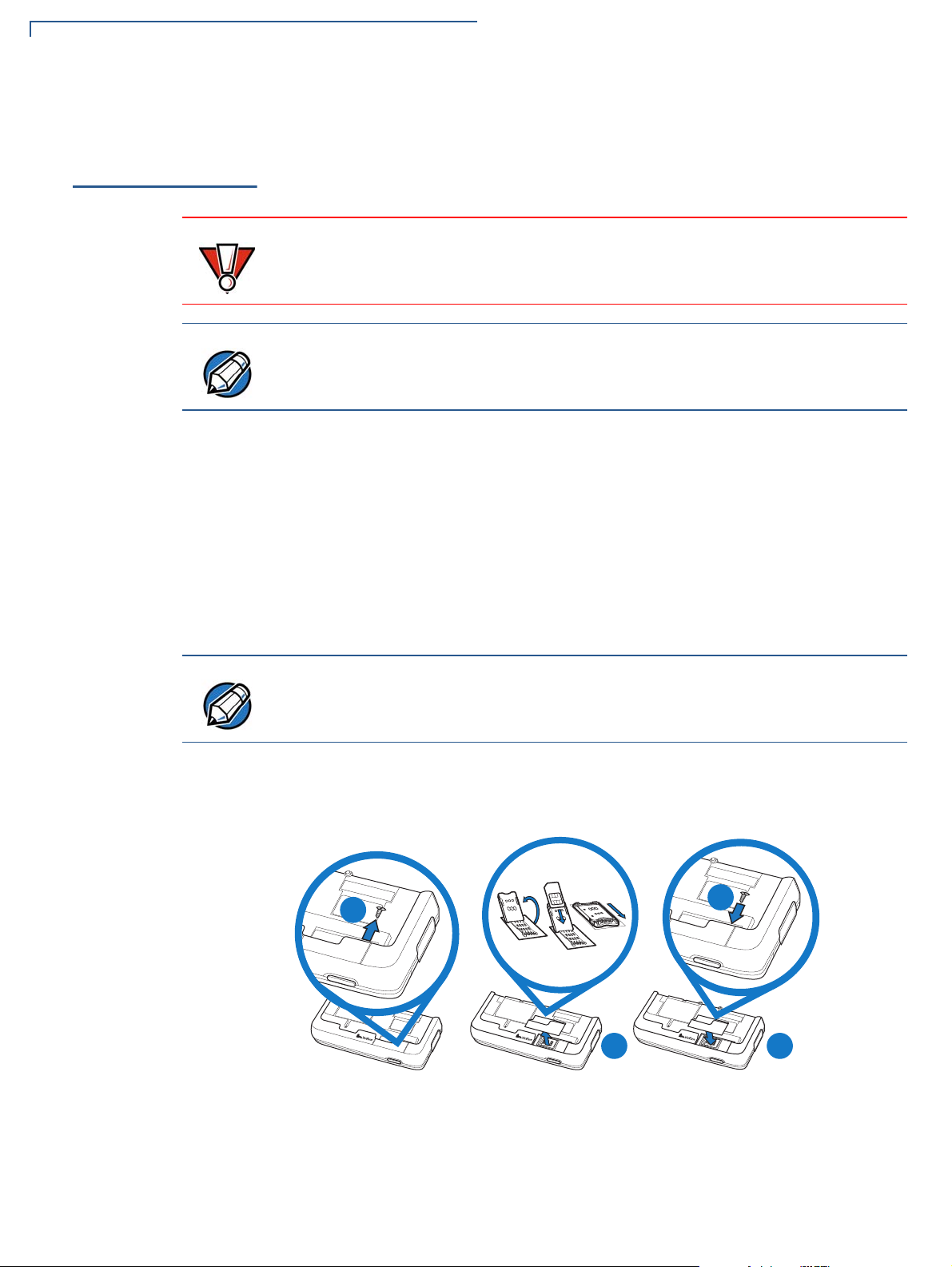
1 Loosen the retaining screw at the back of the SAM cover. The ret aining screw
is captive, which means that it cannot be fully removed from the slot.
2 Pull out the cover to display the MSAM compartment.
3 Unlock the MSAM compartment by pulling the locking tab downwards.
4 Hook your finger under locking tab and lift up to swivel the MSAM tray open.
5 Place the MSAM card on top of the tray with the gold contacts facing down
and then gently push down the tray to close.
Make sure that the MSAM card sits firmly on the tray to be able to close the
MSAM compartment.
6 Push the locking tab upwards to lock the tray and secure the MSAM card.
7 Place the cover back and tighten the screw.
14 E335 INSTALLATION GUIDE
Figure 4 Inserting an MSAM card
Page 15

DEVICE SETUP
C D
1
QZ.
2
ABC
3
DEF
6
MNO
9
WXY
5
JKL
8
TUV
0
X
I
O
#
4
GHI
7
PRS
Cancel
Clear
Enter
”
*
’
,
3
DEF
6
MNO
9
WXY
#
Enter
A
B
1
QZ.
2
ABC
3
DEF
6
MNO
9
WXY
5
JKL
8
TUV
0
X
I
O
#
4
GHI
7
PRS
Cancel
Clear
Enter
”
*
’
,
3
DEF
6
MNO
9
WXY
#
Enter
E
Installing/Removing an iPad mini into the e335
Installing/
Removing an
iPad mini into
the e335
To install an iPad mini
into the e335
The e335 cannot be used as a standalone device. To be able to scan barcodes
and process credit card payments, you need to attach an iPad mini to the e335.
To attach the tablet, the top part of the e335 casing should be removed.
1 Loosen the retaining screw at the back of the e335. The restraining screw is
captive, which means that it cannot be fully removed from the slot.
2 Slide the release button downward to disengage the casing from the main unit.
3 Insert the iPad mini into the casing.
You can now proceed to install the iPad mini.
4 Hold and secure the e335 with the PIN pad facing down.
5 Align the port at the bottom of the iPad mini with the Lightning connector on
the iPad mini then, gently but firmly push the e335 down until it sits firmly.
6 Tighten the screw at the back of the e335 to secure the device.
Figure 5 Installing an iPad mini into the e335
E335 INSTALLATION GUIDE 15
Page 16

DEVICE SETUP
1
QZ.
2
ABC
3
DEF
6
MNO
9
WXY
5
JKL
8
TUV
0
X
I
O
#
4
GHI
7
PRS
Cancel
Clear
Enter
”
*
’
,
3
DEF
6
MNO
9
WXY
#
Enter
A
B
C
1
QZ.
2
ABC
3
DEF
6
MNO
9
WXY
5
JKL
8
TUV
0
X
I
O
#
4
GHI
7
PRS
Cancel
Clear
Enter
”
*
’
,
3
DEF
6
MNO
9
WXY
#
Enter
E
D
NOTE
NOTE
Manually Starting and Shutting Down the e335
To remove the iPad
mini from the e335
Manually
Starting and
Shutting Down
the e335
1 Loosen the retaining screw at the back of the e335.
2 Slide the release button downward to disengage the casing and the iPad mini
from the main unit.
3 Remove the iPad mini from the casing.
4 Hold and secure the e335 with the PIN pad facing down.
5 Return the e335 casing and then tighten the screw at the back.
Figure 6 Removing an iPad mini from the e335
Press the Home button on the iPad mini to automatically turn on the e335.
Similarly, the e335 automatically turns off when the iPad mini is inactive.
Connecting the
e335 to a Power
Source or a Host
Computer
16 E335 INSTALLATION GUIDE
• To reset or manually turn the e335 on, place a paper clip or a similar tool in
the hole located at the bottom of the e335 to press the reset button.
• Press the Cancel key for at least three seconds to manually shut down the
e335.
Plug the wall-mount charger to an external power source and connect it to the
e335 to charge the device. You can also connect the e335 to a computer to
synchronize data and/or charge the device.
• To optimize the charging time, use only a VeriFone certified wall-mount
charger (VPN PWR087-300-01-A)
• Fully charge the e335 device before initial use.
• The e335 device must be fully charged before USB power can be used to
charge the iPad mini.
Page 17

DEVICE SETUP
1
QZ.
2
ABC
3
DEF
6
MNO
9
WXY
5
JKL
8
TUV
0
X
I
O
#
4
GHI
7
PRS
Cancel
Clear
Enter
”
*
’
,
1
QZ.
2
ABC
3
DEF
6
MNO
9
WXY
5
JKL
8
TUV
0
X
I
O
#
4
GHI
7
PRS
Cancel
Clear
Enter
”
*
’
,
NOTE
Connecting the e335 to a Power Source or a Host Computer
To Connect the e335
to a Wall-mount
Charger
To Connect the e335
to a Host Computer
via Micro-USB
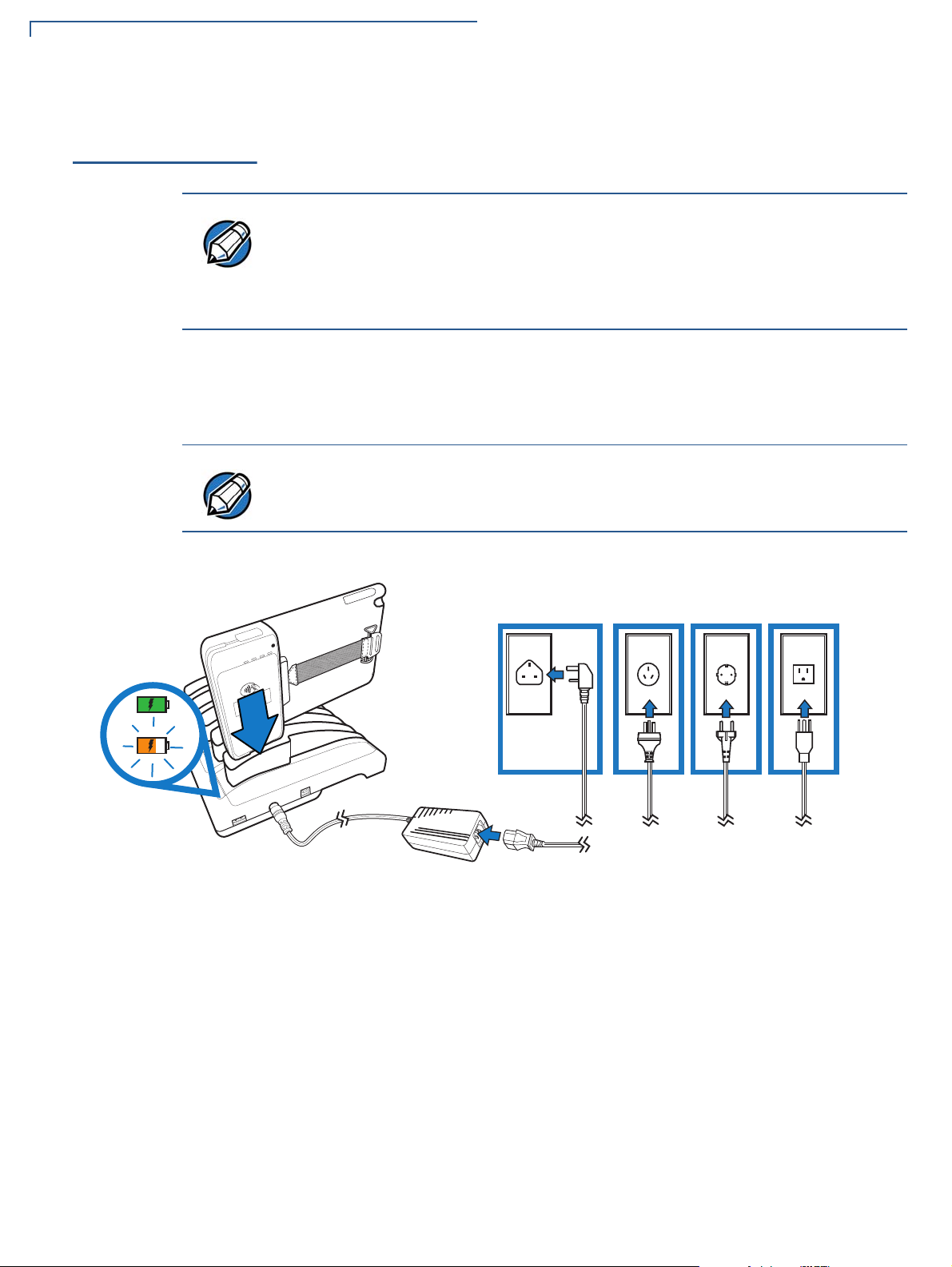
1 Plug the VeriFone-certified wall-mount charger into a wall outlet or powered
surge protector.
2 Insert the Micro-USB cable into the port located on the side of the e335.
Figure 7 Connecting the e335 to a Wall-mount Charger
1 Connect the Micro-USB cable into the port located on the side of the e335.
2 Connect the other end of the Micro-USB cable into the host computer’s USB
port.
Figure 8 Connecting the e335 to a Host Computer
Connecting the e335 to a host computer will not charge the attached iPad mini.
E335 INSTALLATION GUIDE 17
Page 18
DEVICE SETUP
NOTE
NOTE
INI
N
DC IND
C
I
N
OUTO
U
T
1
QZ.
2
ABC
3
DEF
6
MNO
5
JKL
4
GHI
9
WXY
8
TUV
7
PRS
0
#
”
*
’
,
X
I
O
Cancel
Clear
Enter
Using the Gang Charger
Using the Gang
Charger
To charge an e335
device using the
Gang Charger
Use the dedicated e335 Gang Charger to charge up to five e335 units
simultaneously.
• The gang charger LED turns to blinking orange when charging. A solid green
LED color indicates a fully charged e335 device.
• You can also use the e335 Gang Charger to charge e315 devices. Use an
insert (VPN PPL087-533-01-A) to properly attached the e315 device to the
Gang Charger.
1 Plug the wall-mount charger to an external power source and connect it to the
Gang Charger (VPN PWR087-300-0x-A).
2 Plug the other end of the wall charger to the DC IN port on the Gang Charger.
Make sure that the screw on the e335 is properly fastened to prevent damage to
charging cradle or the screw itself.
18 E335 INSTALLATION GUIDE
Figure 9 Charging an e335 device using the gang charger
Page 19

DEVICE SETUP
1
QZ.
2
ABC
3
DEF
6
MNO
5
JKL
9
WXY
1
QZ.
2
ABC
3
DEF
6
MNO
5
JKL
9
WXY
1
QZ.
2
ABC
3
DEF
6
MNO
5
JKL
9
WXY
1
QZ.
2
ABC
3
DEF
6
MNO
5
JKL
9
WXY
1
QZ.
2
ABC
3
DEF
6
MNO
5
JKL
9
WXY
INI
N
DC IND
C
I
N
OUTOU
T
1
QZ.
2
ABC
3
DEF
6
MNO
5
JKL
9
WXY
1
QZ.
2
ABC
3
DEF
6
MNO
5
JKL
9
WXY
1
QZ.
2
ABC
3
DEF
6
MNO
5
JKL
9
WXY
1
QZ.
2
ABC
3
DEF
6
MNO
5
JKL
9
WXY
1
QZ.
2
ABC
3
DEF
6
MNO
5
JKL
9
WXY
ININ
DC IND
C
IN
OUTOU
T
1
QZ.
2
ABC
3
DEF
6
MNO
5
JKL
9
WXY
1
QZ.
2
ABC
3
DEF
6
MNO
5
JKL
9
WXY
1
QZ.
2
ABC
3
DEF
6
MNO
5
JKL
9
WXY
1
QZ.
2
ABC
3
DEF
6
MNO
5
JKL
9
WXY
1
QZ.
2
ABC
3
DEF
6
MNO
5
JKL
9
WXY
INI
N
DC IND
C
I
N
OUTOU
T
1
QZ.
2
ABC
3
DEF
6
MNO
5
JKL
9
WXY
1
QZ.
2
ABC
3
DEF
6
MNO
5
JKL
9
WXY
1
QZ.
2
ABC
3
DEF
6
MNO
5
JKL
9
WXY
1
QZ.
2
ABC
3
DEF
6
MNO
5
JKL
9
WXY
1
QZ.
2
ABC
3
DEF
6
MNO
5
JKL
9
WXY
ININ
DC IND
C
IN
OUTOU
T
1
QZ.
2
ABC
3
DEF
6
MNO
5
JKL
9
WXY
INI
N
DC IND
C
I
N
OUTOUT
Using the Gang Charger
Using Multiple Gang
Chargers
To connect multiple
gang chargers
If you need to charge more than five e335 devices, you can connect up to four
e335 gang chargers in a daisy chain pattern.
1 Plug the wall-mount charger to an external power source and connect it to the
main Gang Charger.
2 Plug the other end of the wall charger to the DC IN port on the main Gang
Charger.
3 Plug one end of the USB Type A to Type B cable (CBL087-405-01-A) to the
OUT port on the main gang charger.
4 Plug the other end of the cable to the IN port on the second gang charger.
5 To make another connection, follow Step 3 and Step 4.
Connecting the
Gang Charger to a
Computer
To connect the Gang
Charger to a
computer
Figure 10 Connecting multiple gang chargers
Use a standard USB Type A to Type B cable to connect the Gang Charger to a
computer. When connected, you can individually access each e335 device in the
Gang Charger.
1 Insert the USB Type A plug to the computer’s USB port.
2 Insert the other end of the cable to the IN port on the Gang Charger.
Figure 11 Connecting the gang charger to a computer
E335 INSTALLATION GUIDE 19
Page 20

DEVICE SETUP
1
QZ.
2
ABC
3
DEF
6
MNO
9
WXY
5
JKL
8
TUV
0
X
I
O
#
4
GHI
7
PRS
Cancel
Clear
Enter
”
*
’
,
NOTE
Understanding LED Color Behavior
Understanding
LED Color
The following table shows the behavior of the LEDs during various system power
states.
Behavior
Deep
Sleep
Battery
Low
Battery
Charging
Y All LEDs are turned off
Y Red, 4Hz rate, 50% duty cycle
Y Orange, 1Hz rate, 50% duty cycle
Using a Smart
Card to Conduct
Transactions
The smart card transaction procedure may vary from one application to another.
Verify the procedure with your application provider before performing a smart card
transaction.
Charging
Timer Fault /
Battery Fault
Y Orange on continuously
Normal
Operation
System LED Behavior
Battery low condition: battery voltage <3.65V
Y Green on continuously
To conduct a smart
card transaction
1 Position the smart card with the contacts facing in the same direction as the
keypad.
2 Insert the card into the reader slot in a smooth, continuous motion until it seats
firmly.
Figure 12 Inserting a Smart Card
3 Wait for the application to indicate a completed transaction before removing
the card. Premature card removal invalidates the transaction.
You will need a valid SIM card to conduct transactions. For more information on
installing/replacing a SIM card, refer to the appropriate Apple documentation or
visit the Apple Web site.
20 E335 INSTALLATION GUIDE
Page 21

DEVICE SETUP
1
QZ.
2
ABC
3
DEF
6
MNO
9
WXY
5
JKL
8
TUV
0
X
I
O
#
4
GHI
7
PRS
Cancel
Clear
Enter
”
*
’
,
XXXXXXXXXXXXXXXX
NOTE
1
QZ.
2
ABC
3
DEF
6
MNO
9
WXY
5
JKL
8
TUV
0
X
I
O
#
4
GHI
7
PRS
Cancel
Clear
Enter
”
*
’
,
Using the Magnetic Stripe Reader
Using the
Magnetic Stripe
Reader
To conduct a credit/
debit card transaction
Use the magnetic stripe reader to perform credit and debit card transactions.
1 Position the card with the magnetic stripe facing the same direction as the
front panel.
2 To ensure a proper read of the magnetic swipe card, insert the magnetic card
from the top of the device, as shown in
Figure 13 Using Magnetic Stripe Card
Figure 13.
Using the CTLS
Reader
3 Swipe the card through the magnetic card reader.
You will need a valid SIM card to conduct transactions. For more information on
installing/replacing a SIM card, refer to the appropriate Apple documentation or
visit the Apple Web site.
The e335 supports contactless credit or debit card transactions.
To perform a contactless transaction, gently tap the card or hold the card against
the surface of the contactless antenna, located above the keypad and LCD with a
CTLS symbol.
Figure 14 Using the CTLS reader
E335 INSTALLATION GUIDE 21
Page 22

DEVICE SETUP
CAUTION
LASER RADIATION
DO NOT STARE INTO BEAM
CLASS 2 LASER PRODUCT
“Complies with 21 CFR 1040.20 and 1040.11 except for deviations
pursuant to laser Notice 50, dated June 24, 2007” 650nm, <1mW
EN 60825-1-2007
IEC 60825-1-2007
1
QZ.
2
ABC
3
DEF
6
MNO
9
WXY
5
JKL
8
TUV
0
X
I
O
#
4
GHI
7
PRS
Cancel
Clear
Enter
”
*
’
,
*DOC087-052-EN-A*
NOTE
Using the Barcode Reader
Using the
Barcode Reader
The two Action buttons located on either side of the e335, activate the barcode
reader (see
Figure 2).
To scan barcodes 1 Press either button to scan barcodes.
2 Point the laser to the target code, adjusting the position as necessary.
Do not release the button until the application indicates a successful scan or
when the product information displays on the tablet screen.
Figure 15 Using the Barcode Reader
When activated, do not point the barcode reader directly at a person to avoid
unnecessary harm or injury.
Use of controls or adjustments or performance of procedures other than those
specified herein may result in hazardous radiation exposure.
22 E335 INSTALLATION GUIDE
Page 23

Specifications
CHAPTER 3
This chapter discusses power requirements, dimensions, and other specifications
of the e335 device.
Power
Temperature
External
Dimensions
Weight
Charging via Micro-USB to computer system or VeriFone-certified power adapter:
5V DC, 2 A
Charging via dedicated e335 Gang Charger:
12V DC, 5 A
• Operating Temperature: -5° to 40°C (23° to 104°F)
Relative humidity: 5% to 95%; RH non-condensing
• Length: 218 mm
• Width:143 mm
• Depth: 26.5 mm
• 240 grams
E335 INSTALLATION GUIDE 23
Page 24

SPECIFICATIONS
Wei ght
24 E335 INSTALLATION GUIDE
Page 25

Maintenance
CAUTION
CHAPTER 4
The e335 device has no user-maintainable parts.
Cleaning the
Device
Smart Card
Reader
To clean the device, use a clean cloth slightly dampened with water and a drop or
two of mild soap. For stubborn stains, use alcohol or an alcohol-based cleaner.
Never use thinner, trichloroethylene, or ketone-based solvents – they may cause
deterioration of plastic or rubber parts.
Do not spray cleaners or other solutions directly onto the keypad or device
display.
Do not attempt to clean the smart card reader. Doing so may void any warranty.
For smart card reader service, contact your VeriFone distributor or service
provider.
E335 INSTALLATION GUIDE 25
Page 26

MAINTENANCE
Smart Card Reader
26 E335 INSTALLATION GUIDE
Page 27

VeriFone Service and Support
NOTE
For e335 problems, contact your local V eriFone represe ntative or service provider .
For e335 product service and repair information:
• USA – VeriFone Service and Support Group, 1-800-VeriFone (837-4366),
Monday - Friday, 8 A.M. - 8 P.M., Eastern time
• International – Contact your VeriFone representative
CHAPTER 5
Returning a
Device for
Service
To return a device for
service
Before returning a e335, you must obtain an MRA number. The following
procedure describes how to return one or more devices for repair or replacement
(U.S. customers only).
Customers outside the United States are advised to contact their local VeriFone
representative for assistance regarding service, return, or replacement of devices
and accessories.
1 Get the following information from the printed labels at the back of each e335
to be returned:
• Product ID, including the model and part number . For example, “e335” a nd
“M087-XXX-XXX-XXX.”
• Serial number (S/N nnn-nnn-nnn)
2 Obtain the MRA number(s) by completing one of the following:
a Call VeriFone toll-free within the United States at 1-800-VeriFone and
follow the automated menu options.
• Select the MRA option from the automated message. The MRA
department is open Monday to Friday, 8
A.M.–8 P.M., Eastern Time.
• Give the MRA representative the information you gathered in Step 1.
If the list of serial numbers is long, you can fax the list, along with the
information gathered in Step 1, to the MRA department at 727-9534172 (U.S.).
b Address a fax to “VeriFone MRA Dept.” with the model and part number(s)
• Include a telephone number where you can be reached and your fax
number.
c Complete the Inquiry Contact Form at http://www.verifone.com/
aboutus/contact/contact_form.cfm.
E335 INSTALLATION GUIDE 27
Page 28

VERIFONE SERVICE AND SUPPORT
NOTE
Accessories and Documentation
• Address the Subject box with to “VeriFone MRA Dept.”
• Reference the model and part number in the Note box.
One MRA number must be issued for each e335 you return to VeriFone, even if
you are returning several of the same model.
3 Describe the problem(s).
4 Provide the shipping address where the repaired or replacement unit must be
returned.
5 Keep a record of the following items:
• Assigned MRA number(s).
• VeriFone serial nu mber assigne d to the e33 5 you are returning for service
or repair (device serial numbers are located at the back of the unit.
Accessories and
Documentation
Accessories
• Shipping documentation, such as air bill numbers used to trace the
shipment.
• Model(s) returned (model numbers are located on the VeriFone label at
the back of the e335).
VeriFone produces the following accessories and documentation for the
e335. When ordering, please take note of the part number.
• VeriFone online store at www.store.verifone.com
• USA – VeriFone Customer Development Center, 800-VeriFone (837-4366),
Monday - Friday, 7 A.M. - 8 P.M., Eastern time
• International – Contact your VeriFone representative
e335 Gang Charger M087-Q04-50-NAA
USB to Micro-USB cable CBL000-021-01-A
VeriFone Certified Wall Mount Chager (e355
device)
VeriFone Certified Power Adapter (Gang Charger) PWR087-300-0X-A
PWR087-300-01-A
Documentation
28 E335 INSTALLATION GUIDE
VeriFone Cleaning Kit
e335 Certifications and Regulations VPN DOC087-051-EN-A
e335 Quick Installation Guide VPN DOC087-052-EN-A
e335 Gang Charger Certifications and Regulations VPN DOC087-055-EN-A
e335 Gang Charger Quick Installation Guide VPN DOC087-056-EN-A
02746-01
Page 29

VERIFONE SERVICE AND SUPPORT
CAUTION
Battery Pack Instructions
Battery Pack
Instructions
Dispose of the battery pack in accordance with all national, state, and local laws
and regulations as regionally required. Some batteries may be recycled and may
be accepted for disposal at local recycling centers.
There is a risk of explosion if the battery is replaced by an incorrect type.
E335 INSTALLATION GUIDE 29
Page 30

VERIFONE SERVICE AND SUPPORT
Battery Pack Instructions
30 E335 INSTALLATION GUIDE
Page 31

CHAPTER 6
NOTE
CAUTION
Troubleshooting
Guidelines
The troubleshooting guidelines provided in the following section are included to
help you install and configure your e335 successfully. Typical examples of
malfunction you may encounter while operating your e335 and steps you can take
to resolve them are listed in this chapter.
If the problem persists even after performing the outlined guidelines or if the
problem is not described below, contact your local VeriFone representative for
assistance.
The e335 comes equipped with tamper-evident labels. The e335 unit contains no
user serviceable parts. Do not, under any circumstance, attempt to disassemble
the device. Perform only those adjustments or repairs specified in this guide. For
all other services, contact your local VeriFone service provider. Service conducted
by parties other than authorized VeriFone representatives may void any warranty.
Use only a VeriFone-supplied power pack. Using an incorrectly rated power
supply may damage the device or cause it not to work as specified. Before
troubleshooting, ensure that the power supply being used to power the device
matches the requirements specified at the bottom of the device. (See
Specifications, for d et a iled power supply sp ecifications.) Obtain the appropriately
rated power supply before continuing with troubleshooting.
Device Does Not
Device Display
Does Not Show
Readable Info
Start
Correct/
• Ensure that the battery charge state is not below the critically low level.
• Recharge the battery.
• Recharge the battery.
• Connect the e335 into a known-good power supply (if available) to see if this
clears the problem.
• If the problem persists, contact your local VeriFone representative for
assistance.
E315 INSTALLATION GUIDE 31
Page 32

TROUBLESHOOTING GUIDELINES
CAUTION
Blank Display
Blank Display
Keypad Does
Not Respond
When the e335 display screen does not show correct or clearly readable
information:
• Check device power connection.
• Remove and reapply power to the device.
• Check if the iPad mini device is properly installed.
• Place a paper clip or a similar tool in the hole located at the bottom of the e335
to press the Reset Button inside to reset the device.
• If the problem persists, contact your local VeriFone service provider.
If the keypad does not respond properly:
• Check the device display. If it displays the wrong character or nothing at all
when you press a key, follow the steps outlined in
Process.
Transactions Fail To
• Check if the iPad mini is properly installed.
• If the problem persists, contact your local VeriFone representative.
• Place a paper clip or a similar tool in the hole located at the bottom of the e335
to press the Reset Button inside to reset the device.
Transactions
Fail To Process
Do NOT paste anything on the keypad surface to avoid malfunction.
There are several reasons why the device may not be processing transactions.
Use the following steps to troubleshoot failures.
Check the Magnetic Card Reader
• Perform a test transaction using one or more different magnetic stripe cards to
ensure the problem is not a defective card.
• The side of the card where the black magnetic stripe is should be visible.
Insert the magnetic stripe card from the top of the device going downwards in
a smooth and continuous manner (see
Check the Smart Card Reader
Figure 13).
• Perform a test transaction using several different smart cards to ensure the
problem is not a defective card.
• Ensure that the card is inserted correctly and that the card is not removed
prematurely.
32 E315 INSTALLATION GUIDE
• Contact your VeriFone distributor or service provider.
Page 33

TROUBLESHOOTING GUIDELINES
Transactions Fail To Process
E315 INSTALLATION GUIDE 33
Page 34

VeriFone, Inc.
2099 Gateway Place, Suite 600
San Jose, CA, 95110 USA
1-800-VERIFONE
www.verifone.com
e335
Installation Guide
VeriFone Part Number DOC087-053-EN-A, Revision A
 Loading...