

Page 1
Verifone Carbon
Installation Guide
C
V
O
E
N
R
F
I
I
F
D
R
N
O
EN
S
I
EV
E
T
IO
I
N
A
A
L
2
.
Verifone Part Number DOC179-003-EN-A, Revision A.2
Page 2

Verifone Carbon Installation Guide
© 2016 Verifone, Inc.
All rights reserved. No part of the contents of this document may be reproduced or transmitted in any form without the written
permission of Verifone, Inc.
The information contained in this document is subject to change without notice. Although Verifone has attempted to ensure the
accuracy of the contents of this document, this document may include errors or omissions. The examples and sample programs are
for illustration only and may not be suited for your purpose. You should verify the applicability of any example or sample program
before placing the software into productive use. This document, including without limitation the examples and software programs, is
supplied “As-Is.”
Verifone and the Verifone logo are registered trademarks of Verifone. Other brand names or trademarks associated with Verifone’s
products and services are trademarks of Verifone, Inc.
All other brand names and trademarks appearing in this manual are the property of their respective holders.
Comments? Please e-mail all comments on this document to your local Verifone Support Team.
Verifone, Inc.
1-800-Verifone
www.verifone.com
Verifone Part Number DOC179-003-EN-A, Revision A.2
Page 3

CONTENTS
PREFACE . . . . . . . . . . . . . . . . . . . . . . . . . . . . . . . . . . . . . . . 5
Audience. . . . . . . . . . . . . . . . . . . . . . . . . . . . . . . . . . . . . . . . . . . . . . . . . . . . . . . . 5
Organization . . . . . . . . . . . . . . . . . . . . . . . . . . . . . . . . . . . . . . . . . . . . . . . . . . . . . 5
Related Documentation . . . . . . . . . . . . . . . . . . . . . . . . . . . . . . . . . . . . . . . . . . . . 5
Conventions and Acronyms . . . . . . . . . . . . . . . . . . . . . . . . . . . . . . . . . . . . . . . . . 6
Document Conventions. . . . . . . . . . . . . . . . . . . . . . . . . . . . . . . . . . . . . . . . . . 6
Acronym Definitions . . . . . . . . . . . . . . . . . . . . . . . . . . . . . . . . . . . . . . . . . . . . 6
CHAPTER 1
Device Overview Features and Benefits . . . . . . . . . . . . . . . . . . . . . . . . . . . . . . . . . . . . . . . . . . . . . 9
Connectivity . . . . . . . . . . . . . . . . . . . . . . . . . . . . . . . . . . . . . . . . . . . . . . . . . . 9
Performance . . . . . . . . . . . . . . . . . . . . . . . . . . . . . . . . . . . . . . . . . . . . . . . . . . 9
Security . . . . . . . . . . . . . . . . . . . . . . . . . . . . . . . . . . . . . . . . . . . . . . . . . . . . . 10
Exceptional Ease of Use. . . . . . . . . . . . . . . . . . . . . . . . . . . . . . . . . . . . . . . . 10
CHAPTER 2
Setup Selecting Unit Location. . . . . . . . . . . . . . . . . . . . . . . . . . . . . . . . . . . . . . . . . . . . 13
Modular Countertop Performance. . . . . . . . . . . . . . . . . . . . . . . . . . . . . . . . . 10
True Multi-Application Capability . . . . . . . . . . . . . . . . . . . . . . . . . . . . . . . . . 11
A
N
Ease of Use . . . . . . . . . . . . . . . . . . . . . . . . . . . . . . . . . . . . . . . . . . . . . . . . . 13
Environmental Factors . . . . . . . . . . . . . . . . . . . . . . . . . . . . . . . . . . . . . . . . . 13
Electrical Considerations . . . . . . . . . . . . . . . . . . . . . . . . . . . . . . . . . . . . . . . 14
PIN Protection Measures . . . . . . . . . . . . . . . . . . . . . . . . . . . . . . . . . . . . . . . 14
Unpacking the Shipping Carton . . . . . . . . . . . . . . . . . . . . . . . . . . . . . . . . . . . . . 14
Periodic Inspection . . . . . . . . . . . . . . . . . . . . . . . . . . . . . . . . . . . . . . . . . . . . . . . 15
Examining the Unit’s Features . . . . . . . . . . . . . . . . . . . . . . . . . . . . . . . . . . . . . . 16
Verifone Carbon Features. . . . . . . . . . . . . . . . . . . . . . . . . . . . . . . . . . . . . . . 16
Connection Ports . . . . . . . . . . . . . . . . . . . . . . . . . . . . . . . . . . . . . . . . . . . . . 17
Establishing Communication . . . . . . . . . . . . . . . . . . . . . . . . . . . . . . . . . . . . . . . 19
Connecting by Ethernet Cable . . . . . . . . . . . . . . . . . . . . . . . . . . . . . . . . . . . 19
Loading a Paper Roll in the Printer. . . . . . . . . . . . . . . . . . . . . . . . . . . . . . . . . . . 19
Installing or Replacing MSAM Cards . . . . . . . . . . . . . . . . . . . . . . . . . . . . . . . . . 21
Connecting Optional Devices . . . . . . . . . . . . . . . . . . . . . . . . . . . . . . . . . . . . . . . 23
Optional Device Connections . . . . . . . . . . . . . . . . . . . . . . . . . . . . . . . . . . . . 23
Connecting ECRs to the Verifone Carbon . . . . . . . . . . . . . . . . . . . . . . . . . . 24
Connecting the Terminal Power Pack . . . . . . . . . . . . . . . . . . . . . . . . . . . . . . . . 24
Using the Smart Card Reader . . . . . . . . . . . . . . . . . . . . . . . . . . . . . . . . . . . . . . 26
Using the Magnetic Card Reader . . . . . . . . . . . . . . . . . . . . . . . . . . . . . . . . . . . . 26
Using the Contactless Reader . . . . . . . . . . . . . . . . . . . . . . . . . . . . . . . . . . . . . . 27
E
R
SIO
VI
.
2
CHAPTER 3
Specifications Technical Specifications . . . . . . . . . . . . . . . . . . . . . . . . . . . . . . . . . . . . . . . . . . . 29
Swordfish . . . . . . . . . . . . . . . . . . . . . . . . . . . . . . . . . . . . . . . . . . . . . . . . . . . 29
Tablet . . . . . . . . . . . . . . . . . . . . . . . . . . . . . . . . . . . . . . . . . . . . . . . . . . . . . . 30
Stand. . . . . . . . . . . . . . . . . . . . . . . . . . . . . . . . . . . . . . . . . . . . . . . . . . . . . . . 30
Printer Stand . . . . . . . . . . . . . . . . . . . . . . . . . . . . . . . . . . . . . . . . . . . . . . . . . 31
VERIFONE CARBON INSTALLATION GUIDE 3
Page 4

CONTENTS
CHAPTER 4
Maintenance and
Cleaning
CHAPTER 5
Service and Support Service Returns . . . . . . . . . . . . . . . . . . . . . . . . . . . . . . . . . . . . . . . . . . . . . . . . . 35
CHAPTER 6
Troubleshooting
Guidelines
CHAPTER 7
Port Pinouts Verifone Carbon Port Pinout Definitions. . . . . . . . . . . . . . . . . . . . . . . . . . . . . . . 45
Additional Safety Information . . . . . . . . . . . . . . . . . . . . . . . . . . . . . . . . . . . . . . . 33
Potentially Explosive Environments . . . . . . . . . . . . . . . . . . . . . . . . . . . . . . . 33
Accessories and Documentation . . . . . . . . . . . . . . . . . . . . . . . . . . . . . . . . . . . . 37
Connection Cables . . . . . . . . . . . . . . . . . . . . . . . . . . . . . . . . . . . . . . . . . . . . 37
Power Cables . . . . . . . . . . . . . . . . . . . . . . . . . . . . . . . . . . . . . . . . . . . . . . . . 37
Cleaning Kit. . . . . . . . . . . . . . . . . . . . . . . . . . . . . . . . . . . . . . . . . . . . . . . . . . 37
Documentation . . . . . . . . . . . . . . . . . . . . . . . . . . . . . . . . . . . . . . . . . . . . . . . 38
Blank Display . . . . . . . . . . . . . . . . . . . . . . . . . . . . . . . . . . . . . . . . . . . . . . . . . . . 39
Terminal Does Not Dial Out . . . . . . . . . . . . . . . . . . . . . . . . . . . . . . . . . . . . . . . . 39
Printer Paper Jam. . . . . . . . . . . . . . . . . . . . . . . . . . . . . . . . . . . . . . . . . . . . . . . . 40
Keypad Does Not Respond . . . . . . . . . . . . . . . . . . . . . . . . . . . . . . . . . . . . . . . . 40
Peripheral Device Does Not Work . . . . . . . . . . . . . . . . . . . . . . . . . . . . . . . . . . . 41
Transactions Fail To Process . . . . . . . . . . . . . . . . . . . . . . . . . . . . . . . . . . . . . . . 41
Printer Does Not Print. . . . . . . . . . . . . . . . . . . . . . . . . . . . . . . . . . . . . . . . . . . . . 42
Terminal Display Does not Show Correct or Readable Information . . . . . . . . . . 42
Printer Blade Jams or Printer Door Can’t be Closed . . . . . . . . . . . . . . . . . . . . . 43
A
.
2
N
Ethernet Port (LAN) . . . . . . . . . . . . . . . . . . . . . . . . . . . . . . . . . . . . . . . . . . . 45
USB Pinout . . . . . . . . . . . . . . . . . . . . . . . . . . . . . . . . . . . . . . . . . . . . . . . . . . 45
E
USB Mini-B Pinout . . . . . . . . . . . . . . . . . . . . . . . . . . . . . . . . . . . . . . . . . . . . 46
SIO
VI
R
APPENDIX A
Caution and
Warning Messages
Verifone Carbon Caution and Warning Messages . . . . . . . . . . . . . . . . . . . . . . . 47
4 VERIFONE CARBON INSTALLATION GUIDE
Page 5

PREFACE
This guide is the primary source of information for setting up and installing the
Verifone Carbon.
Audience
Organization
This guide describes the card reader’s features, and provides the basic
information for its installation and configuration.
This guide is organized as follows:
Chapter 1, Device Overview. Provides an overview of the device.
Chapter 2, Setup. Explains setup and installation of the device, selecting a
location, and establishing connections with other devices.
Chapter 3, Specifications. Discusses the power requirements and dimensions of
the device.
.
2
Chapter 4, Maintenance and Cleaning. Explains maintenance of the device.
Chapter 5, Service and Support. Provides information on contacting your Verifone
service provider and information on how to order accessories or documentation
from Verifone.
Chapter 6, Troubleshooting Guidelines. Provides troubleshooting guidelines
should you encounter a problem with unit installation and configuration.
E
SIO
VI
N
A
R
Chapter 7, Port Pinouts. Shows the different pinout settings for ports on the
Verifone Carbon
Related
Documentation
Appendix A, Caution and Warning Messages. Shows the UL/cUL certification-
compliant translations of all Warning and Caution messages in this installation
guide.
To learn more about the card reader and controller device, refer to the following
set of documents and their associated Verifone Part Numbers (VPNs).
Verifone Carbon Certifications and Regulations Sheet VPN DOC179-001-EN
Verifone Carbon Quick Installation Guide VPN DOC179-002-EN
Verifone Carbon Reference Guide VPN DOC179-004-EN
Verifone Carbon Printer Stand Certifications and
Regulations Sheet
Verifone Carbon Security Policy VPN DOC420-008-EN
VERIFONE CARBON INSTALLATION GUIDE 5
VPN DOC179-005-EN
Page 6
PREFACE
NOTE
CAUTION
WARNING
Conventions and Acronyms
Conventions and
Acronyms
Document
Conventions
Acronym Definitions
This section describes the conventions and acronyms used in this guide.
Various conventions are used to help you quickly identify special formatting.
Table 1 describes these conventions and provides examples of their use.
Table 1 Document Conventions
Convention Meaning Example
Blue
Text in blue indicates terms that
are cross referenced.
The pencil icon is used to
highlight important information.
The caution symbol indicates
possible hardware or software
failure, or loss of data.
See Conventions and
Acronyms.
If exchanging cables, use a
Verifone-approved cable.
Using an incorrectly rated power
supply can damage the unit or
cause it to malfunction.
2
.
N
A
For safety, do not string cables
or cords across a walkway.
The lightning symbol is used as
a warning when bodily injury
might occur.
SIO
VI
E
R
Various acronyms are used in place of the full definition. Table 2 presents
acronyms and their definitions.
Table 2 Acronym Definitions
6 VERIFONE CARBON INSTALLATION GUIDE
Acronym Definitions
COM Communications port
CTLS Contactless
EMV Europay, MasterCard, and Visa
ETH Ethernet
HW Hardware
I/O Input/Output
ITP Internal thermal printer
LCD Liquid crystal display
LPS Lines per second
MSAM Micromodule-Size Secure Access Module
MSR Magnetic-stripe card reader
PCI Payment Card Industry
PIN Personal Identification Number
POI Point of Interaction
Page 7

Table 2 Acronym Definitions (continued)
Acronym Definitions
PTS PIN Transaction Security
QVGA Quarter Video Graphics Array
RJ45 Registered Jack 45 modular connector
SAM Secure Access Module
SC Smart card
SCR Smart card reader
SD Secure Digital
SDA Static Data Authentication
SDHC Secure Digital High Capacity
SIM Subscriber Identity Module
SMA SubMiniature version A connector
TFT Thin-film transistor
TLS Transport Layer Security
UI User interface
USB Universal Serial Bus
A
.
2
N
PREFACE
Conventions and Acronyms
R
SIO
VI
E
ERIFONE CARBON INSTALLATION GUIDE 7
V
Page 8

PREFACE
Conventions and Acronyms
R
E
VI
SIO
N
A
.
2
8 VERIFONE CARBON INSTALLATION GUIDE
Page 9

Device Overview
NOTE
NOTE
CHAPTER 1
This chapter provides a brief description of the Verifone Carbon system, a
modular merchant- and consumer-facing device, enabling use as a handheld or
stand-mounted payment solution.
Features and
Benefits
Connectivity
Verifone Carbon provides magnetic-stripe card reader (MSR), smart card (SC)
and contactless (CTLS) payment processing with a 5-inch (12.7 cm) color TFT
capacitive touch panel LCD screen, integrated with a 10 or 8 inch (25.4 or 20.32
cm) tablet. The Printer Stand provides additional expansion options (such as a bar
code scanner and weighing scale), connectivity features (USB, MOD 10, telco and
RJ45) as well as power charging and an optional internal thermal printer (ITP)..
A
.
2
Verifone ships variants of the Verifone Carbon system for different markets. Your
device may have different features described in this section.
N
• Device port
SIO
VI
• High speed USB2.0 connection with tablet
E
R
• Interface to tablet on USB 2.0 port 0
• Host port (OS downloads) on micro USB type AB connector
• Interface on USB 2.0 port 1 (Please refer to section 5.8 of ERS for details)
• Unpowered RS232 with no handshake (key loading) on micro USB type AB
connector
Performance
• RX/TX only using (VPNCBL179-100-01-A)
You can find the Verifone Carbon ports on the lower right area behind the 5-inch
screen. The Printer Stand ports are accessible from the underside of the unit,
while the tablet ports and slots are on the sides of the lower right corner.
• Verifone Carbon:
• 4GB RAM and 512MB Flash memory
• 5-inch color TFT display capacitive touch panel LCD (854 x 480)
• Software-controlled backlight
• WiFi and Bluetooth enabled
• Integrated external speaker
VERIFONE CARBON INSTALLATION GUIDE 9
Page 10

DEVICE OVERVIEW
Features and Benefits
• Tablet:
• 8 or 10-inch color TFT display capacitive touch panel LCD (1280 x 800)
• Barcode scanning enabled for front and rear cameras
• Provides power and data to Verifone Carbon unit
• WiFi and Bluetooth enabled
• Integrated external speaker
• Optional 3G or 4G
• Printer Stand:
• USB 2.0 high-speed connections
• Provides ETH and WiFi to Verifone Carbon + tablet unit
• Provides power and data to Verifone Carbon + tablet unit
• Cash drawer interface
Security
Exceptional Ease of
Use
• Optional printer
.
2
• PCI PTS POI v4.x approved for debit and other PIN-based transactions
• EMV L1 Type Approval (contact and contactless)
• Tamper-resistant construction, TLS protocols, and VeriShield file
authentication
• Supports VeriShield Protect encryption implementations.
SIO
VI
N
A
E
R
• Capacitive touch-screen UI access for merchant and customer.
• Signature capture screen capability.
• The contactless (CTLS) functionality offers a convenient payment option for
consumers.
• The triple-track, high-coercivity card reader handles most magnetic stripe
cards.
• EMV card reader ensures secure payment option.
• Large (5-inch for customers, 8- or 10-inch for merchants) LCD displays
simplify training and reduce help desk calls.
• The multiple font-capable optional thermal printer simplifies paper loading and
reduces paper jams. Uses 80 mm wide x 80 mm diameter paper rolls, prints at
30 lines per second (LPS).
Modular Countertop
Performance
10 VERIFONE CARBON INSTALLATION GUIDE
• The 32-bit processing and multi-tasking capabilities ensures fast processing of
payment, payment-related, and value-added applications.
• Exceptional displays and optional printer graphics-handling capabilities that
quickly render logos, graphical fonts, and character-based languages.
Page 11

DEVICE OVERVIEW
Features and Benefits
• The Verifone Carbon ensures uncompromising reliability from Verifone, the
worldwide leader in e-payment.
True Multi-
Application
Capability
• The Verifone Carbon offers 4 GB and 512 MB of dynamic memory allocation
for the operating system, which supports multiple applications on a single
terminal.
• The primary smart card reader and the MSAMs safeguard sensitive financial
data and support multiple smart card schemes.
• Verifone Carbon units are certified for ISO 7816-1 and ISO 7816-2 standards
for smart card solutions, as well as ISO 14443 type A & B and ISO 18092
standards for CTLS operations.
• The VeriShield security architecture meets published specifications for PCI
PTS POI and provides sophisticated file authentication to prevent execution of
unauthorized software on Verifone Carbon devices.
2
.
A
N
SIO
VI
E
R
ERIFONE CARBON INSTALLATION GUIDE 11
V
Page 12

DEVICE OVERVIEW
Features and Benefits
R
E
VI
SIO
N
A
.
2
12 VERIFONE CARBON INSTALLATION GUIDE
Page 13

Setup
CHAPTER 2
This chapter describes the setup procedures for the Verifone Carbon terminal,
under the following sections:
• Selecting Unit Location
• Unpacking the Shipping Carton
• Examining the Unit’s Features
• Establishing Communication
• Loading a Paper Roll in the Printer
• Installing or Replacing MSAM Cards
Selecting Unit
Location
Ease of Use
Environmental
Factors
.
2
• Connecting Optional Devices
• Connecting the Terminal Power Pack
• Using the Smart Card Reader
• Using the Magnetic Card Reader
SIO
N
A
VI
Use the following guidelines when selecting a location for your device.
E
R
• Select a location convenient for both merchant and cardholder.
• Select a flat support surface, such as a countertop or table.
• Select a location near a power outlet and a network, telephone, or modem line
connection.
• For safety, do not string the power cord in a walkway or place it across a
walkway on the floor.
• The unit must be used in an attended environment.
• Do not use the terminal where there is high heat, dust, humidity, moisture, or
caustic chemicals or oils.
• Keep the unit away from direct sunlight and anything that radiates heat, such
as a stove or motor.
VERIFONE CARBON INSTALLATION GUIDE 13
Page 14

SETUP
CAUTION
Unpacking the Shipping Carton
• Do not use the unit outdoors.
The Verifone Carbon is not waterproof or dustproof, and is intended for indoor
use only.
Any damage to the unit from exposure to rain or dust may void any warranty.
Electrical
Considerations
PIN Protection
Measures
• Avoid using the Verifone Carbon during electrical storms.
• Place the Verifone Carbon 10 cm away from metallic objects to avoid
interference with the CTLS field.
• Avoid locations near electrical appliances or other devices that cause
excessive voltage fluctuations or emit electrical noise (for example, air
conditioners, electric motors, neon signs, high-frequency or magnetic security
devices, or computer equipment).
• Do not use the terminal near water or in moist conditions.
You can employ several techniques for effective PIN entry screening on the
keypad. Use the following methods in combination or singly, as necessary:
• Position the Verifone Carbon on the printer stand in such a way as to make
visual observation of the PIN entry process infeasible. Examples include:
• Visual shields designed into the check-stand. These shields may be solely
for shielding purposes, or may be part of the general check-stand design.
• Position the Verifone Carbon so that it is angled in such a way that PIN
E
spying is difficult.
R
• Position the in-store security cameras so that PIN entry is not visible.
SIO
VI
N
A
.
2
14 VERIFONE CARBON INSTALLATION GUIDE
Unpacking the
Shipping Carton
To unpack the
shipping carton
• Use signage to limit the view of the Verifone Carbon to just that of the
cardholder.
• Offer PIN security literature at the point of sale.
Open the shipping carton and carefully inspect its contents for possible tampering
or shipping damage. The Verifone Carbon is a secure product and any tampering
may cause the device to cease to function properly.
1 Validate the authenticity of the sender by verifying the shipping tracking
number and other information located on the product order paperwork.
2 Remove and inspect the following items:
• Verifone Carbon terminal integrated with 10- or 8-inch tablet
• Stand with or without Printer
• Power pack
• Telephone line cord
• Paper roll
Page 15

Periodic Inspection
NOTE
WARNING
Refer to Accessories and Documentation for more information about the
device’s related accessories.
Verifone ships variants of the Verifone Carbon for different markets. Your unit
may have different accessories described in this section.
3 Remove all plastic wrapping from the terminal and other components.
4 Remove the clear protective film from the displays.
5 Save the shipping carton and packing material for future repacking or moving
of the device.
Do not use a unit that has been tampered with or otherwise damaged. This unit
comes equipped with tamper-evident labels. If a label or component appears
damaged, immediately notify the shipping company and your Verifone
representative or service provider.
SETUP
Periodic
Inspection
Periodically inspect the Verifone Carbon terminal for possible tampering. Signs of
tampering include:
• Wires protruding out of the device.
A
.
2
N
• Foreign objects inserted into the smart card slot or magnetic stripe slot.
• Signs of damage to the tamper-evident labels.
• A Tamper Warning message on the device display.
E
SIO
VI
R
If any device is found in tamper state, please remove it from service immediately,
keep it available for potential forensics investigation, and notify your company
security officer and your local Verifone representative or service provider. For
contacting Verifone, please see “Service and Support”.
ERIFONE CARBON INSTALLATION GUIDE 15
V
Page 16
SETUP
Examining the Unit’s Features
Examining the
Unit’s Features
Verifone Carbon
Features
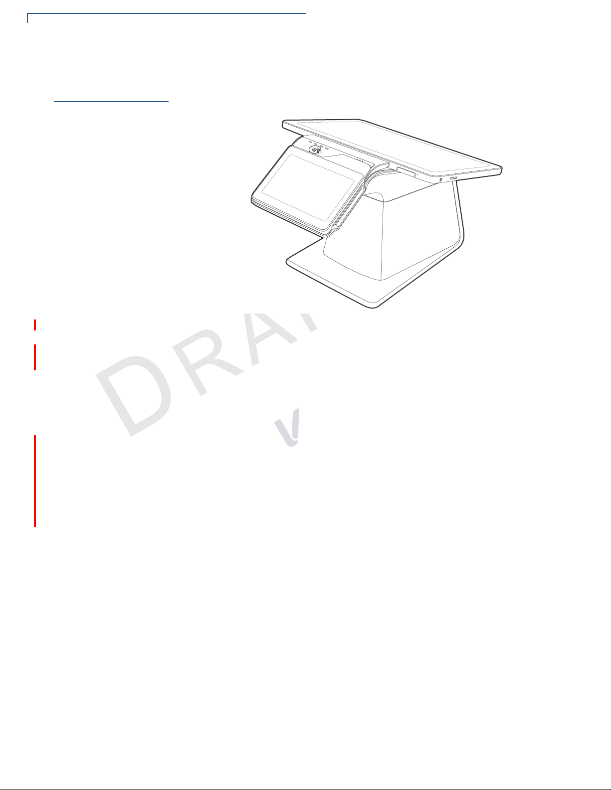
Before you continue the installation process, review the features of the device
(see Figure 1).
Figure 1 Verifone Carbon Mounted on Printer Stand
The Verifone Carbon terminal presents the following:
• A touchscreen LCD display. The upper left edge of the screen acts as the
tapping area for contactless transactions.
N
A
.
2
• A magnetic card reader, built into the top right edge of the screen. The arrows
indicate swipe direction.
E
R
• A smart card reader built into the right side of the screen.
• 8- or 10-inch display
• Printer Stand
• The internal thermal printer door opens with a push on the right-side button.
• Printer indicator LED
SIO
VI
16 VERIFONE CARBON INSTALLATION GUIDE
Page 17

SETUP
WARNING
NOTE
Examining the Unit’s Features
Connection Ports
Turn the printer stand upside down to view the connection ports. The ports provide
communications, peripheral device connections, and power supply.
Figure 2 shows the power, communications and connection ports for the Verifone
Carbon printer stand.
2
.
A
Figure 2 Power and Communication Ports
N
To use the
connection ports
Do not connect the device to the power supply until all peripherals are attached.
SIO
VI
E
The connection ports offer multiple connectivity for the Verifone Carbon terminal.
Please refer to the following list of peripheral devices for the connectivity options.
Verifone ships variants of the Verifone Carbon terminals for different markets.
Your terminal may have different features described in this section.
Host USB Port
• PIN Pads
• Barcode readers
• Biometric readers
• USB flash disk
• USB keyboards
Ethernet Port
R
• Ethernet cable to router, hub or switch
Multi-Communication Port (USB/RS-232)
• PIN Pads
ERIFONE CARBON INSTALLATION GUIDE 17
V
Page 18

SETUP
NOTE
Examining the Unit’s Features
• Computers
• ECRs
• Check readers
• CTLS readers
• Biometric readers
• Barcode readers
• Keyboards
Te lc o Po rt
• Telephone line with 56K modem
The MOD 10 RS-232 + USB/Mini-USB Multi-Communication dongles (VPN
CBL420-002-01-A and CBL420-002-02-A) support the following:
• PIN Pads
• Computers
• ECRs
• Check readers
• CTLS readers
• Biometric readers
N
A
.
2
SIO
• Barcode readers
VI
E
• Keyboards
R
The Multi-Communication port supplies 11.6 V / 365 mA to power accessories
(PIN pads and powered RS-232 devices). It is SW configurable to Host or Client
and supplies 5 V, 500 mA to external USB devices.
For information on how to attach peripheral devices, see Connecting Optional
Devices.
18 VERIFONE CARBON INSTALLATION GUIDE
Page 19

SETUP
CAUTION
Establishing Communication
Establishing
Communication
Connecting by
Ethernet Cable
Loading a Paper
Roll in the
Printer
You can connect the Verifone Carbon Printer Stand to your network using an
ethernet cable. You can also connect using the Wi-Fi option on the Verifone
Carbon.
Connect the ethernet cable to the ETH port on the printer stand, then route it
directly to a network jack (see Figure 3). This is a direct connection to your
network.
2
.
A
Figure 3 Ethernet Connection
Before you can process transactions that require a receipt, you must install paper
in the printer.
SIO
VI
The Verifone Carbon Printer Stand uses a roll of 57 mm wide x 40 mm, single-ply,
thermal sensitive paper.
E
R
N
A pink out-of-paper indicator line appears on the edge of the paper before the end
of the roll. After this line appears, there is enough paper remaining on the roll to
conclude at least one more transaction.
Poor-quality paper can jam the printer and create excessive paper dust. To order
high-quality Verifone paper, refer to Accessories and Documentation.
Store thermal paper in a dry, dark area. Handle thermal paper carefully: impact,
friction, temperature, humidity, and oils affect the color and storage
characteristics of the paper.
Never load a roll of paper with folds, wrinkles, tears, or holes at the edges.
ERIFONE CARBON INSTALLATION GUIDE 19
V
Page 20

SETUP
Loading a Paper Roll in the Printer
To install a paper roll 1 Press the printer door button. See Figure 4).
Figure 4 Opening the Printer Door
2 Remove any partial roll of paper in the tray.
3 Loosen the glued leading edge of the new paper roll or remove the protective
strip. Unwind the paper roll past any glue residue.
4 Hold the roll so the paper feeds from the bottom of the roll.
A
.
2
5 Gently drop the paper roll into the printer tray.
N
SIO
VI
E
R
Figure 5 Loading Paper Roll
6 Pull paper up past the glue residue.
20 VERIFONE CARBON INSTALLATION GUIDE
Page 21

SETUP
NOTE
CAUTION
NOTE
Installing or Replacing MSAM Cards
7 Close the printer door by swinging upward until the door clicks shut, allowing a
small amount of paper past the glue residue to extend outside the printer door.
(see Figure 6).
Figure 6 Closing Printer Door
Installing or
Replacing MSAM
Cards
To install or replace
MSAMs
For paper ordering information, refer to Accessories and Documentation.
A
When you first receive your Verifone Carbon, you may need to install one or more
MSAM cards, or you may need to replace old cards.
SIO
N
.
2
VI
E
R
Observe standard precautions when handling electrostatically sensitive devices.
Electrostatic discharges can damage this equipment. Verifone recommends
using a grounded anti-static wrist strap.
Verifone ships variants of the Verifone Carbon device for different markets. Your
unit may have different features described in this section.
1 Remove the power pack from the power outlet.
2 Place the unit upside down on a soft, clean surface to protect the display from
scratches.
ERIFONE CARBON INSTALLATION GUIDE 21
V
Page 22

SETUP
Installing or Replacing MSAM Cards
3 Hook your finger on the latch and lift the cover to access the MSAM card slot.
Figure 7 Opening the MSAM Cover
4 Remove any previously installed MSAM cards from the cardholder.
A
.
2
5 Install an MSAM card by carefully sliding it into the slot until it is fully inserted.
N
SIO
VI
E
R
Figure 8 Installing an MSAM Card
22 VERIFONE CARBON INSTALLATION GUIDE
Page 23

6 Swing the MSAM cover down to secure it in place.
CAUTION
NOTE
CAUTION
Figure 9 Closing MSAM Cover
SETUP
Connecting Optional Devices
Connecting
Optional
Devices
Optional Device
Connections
The Verifone Carbon device supports some peripheral devices designed for use
with electronic point-of-sale terminals.
A
.
2
N
Before connecting any peripheral device, remove the power plug from the
terminal. Reconnect the power cord only after you are finished connecting the
peripheral device(s). For complete information about peripheral installation and
use, refer to the user documentation supplied with those devices.
Different terminals support different devices, so for more information about
optional devices, please contact your Verifone distributor.
You can connect several devices to your Verifone Carbon. For reference, see To
use the connection ports for the list of devices you can connect to the Verifone
Carbon.
You can use the MOD 10 RS-232 + USB/Mini-USB Multi-Communication dongle
(VPN CBL420-002-01-A and CBL420-002-02-A) as a PIN pad port or an RS-232
port, depending on the power source available.
Make sure you replace the rear cover when all cables are installed. This provides
some protection to the cables and connectors. Do not carry the terminal by the
installed cables or pull the terminal about the by the cables. This may cause a
cable to be removed or damage the cables.
E
R
SIO
VI
Some devices (ECRs and some PIN pads) require a separate power source.
Before connecting to any device, remove the power cord from the Verifone
Carbon unit.
ERIFONE CARBON INSTALLATION GUIDE 23
V
Page 24

SETUP
CAUTION
NOTE
Connecting the Terminal Power Pack
Contact your Verifone representative or visit the online store at
www.store.verifone.com for information on these devices.
Connecting ECRs to
the Verifone Carbon
Connecting the
Terminal Power
Pack
The Verifone Carbon supports electronic cash registers (ECRs).
The following illustration shows how to make a peripheral connection to the MultiCommunication port using the MOD 10 RS-232 + USB Multi-Communication
dongle (VPN CBL420-002-01-A)
2
.
A
Figure 10 Sample ECR Connection
After connecting optional peripherals, prepare to connect the Verifone Carbon to
your power source.
E
SIO
VI
N
R
24 VERIFONE CARBON INSTALLATION GUIDE
To connect the
terminal power pack
Using an incorrectly rated power supply may damage the terminal or cause it not
to work as specified. Before troubleshooting, ensure that the power supply being
used to power the terminal matches the requirements specified on the bottom of
the terminal. (See Chapter 3, Technical Specifications, for detailed power supply
specifications.) Obtain the appropriately rated power supply before continuing
with troubleshooting.
Plugging in the power pack to a power source automatically turns on the
terminal.
1 Remove the terminal rear cover to access the power port.
Page 25

Connecting the Terminal Power Pack
WARNING
2 Insert the round barrel connector (see A in Figure 11) into the power port.
Figure 11 Power Connection
SETUP
3 Connect the power adapter to the power brick (see B in Figure 11).
4 Plug the AC power pack into a wall outlet or powered surge protector.
Do not plug the power pack into an outdoor outlet or operate the terminal
outdoors.
Disconnecting the power during a transaction may cause transaction data files
not yet stored in terminal memory to be lost.
SIO
VI
N
A
.
2
E
To protect against possible damage caused by lightning strikes and electrical
surges, consider installing a power surge protector.
The screens activate when the device has power.
If the terminal comes pre-loaded with an application, this starts after the initial
Verifone copyright screen and usually displays its own copyright screen.
R
ERIFONE CARBON INSTALLATION GUIDE 25
V
Page 26

SETUP
CAUTION
Using the Smart Card Reader
Using the Smart
Card Reader
To conduct a smart
card transaction
The smart card transaction procedure may vary from one application to another.
Verify the procedure with your application provider before performing a smart card
transaction.
1 Position a smart card with the contacts facing upward (see Figure 12).
2 Insert the smart card into the smart card reader slot in a smooth, continuous
motion until it seats firmly.
3 Remove the card only when the application indicates the transaction is
complete.
2
.
A
Figure 12 Inserting a Smart Card
N
Using the
Magnetic Card
Reader
To conduct a credit or
debit card transaction
SIO
Leave the smart card in the card reader until the transaction is complete.
VI
E
Premature card removal will invalidate the transaction.
R
The Verifone Carbon terminal supports credit or debit card transactions.
1 Position the card with the magnetic stripe oriented downward, facing the
reader.
26 VERIFONE CARBON INSTALLATION GUIDE
Page 27

Using the Contactless Reader
2 To ensure a proper read of the magnetic stripe, swipe the card smoothly
through the reader in one direction (either to the left or to the right), as shown
in Figure 13.
Figure 13 Using the Magnetic Card Reader
3 Check the screen for confirmation of a successful transaction.
SETUP
Using the
Contactless
Reader
To perform a CTLS
transaction
Verifone Carbon provides a third alternative to paying for goods and services:
CTLS.
2
.
A
1 Hold the card (within 4 cm) or gently tap against the surface of the contactless
antenna, marked by the logo .
N
SIO
VI
E
R
Figure 14 Conducting a Contactless Transaction
2 After you tap your card, the LEDs will light up and the buzzer will sound for
about 2 seconds, prompting you to remove your card.
ERIFONE CARBON INSTALLATION GUIDE 27
V
Page 28

SETUP
Using the Contactless Reader
R
E
VI
SIO
N
A
.
2
28 VERIFONE CARBON INSTALLATION GUIDE
Page 29

Specifications
CHAPTER 3
This chapter discusses power requirements, dimensions, and other specifications
of the Verifone Carbon system.
Technical
Specifications
Swordfish
Refer to the following information on the power, weight, temperature, memory,
ports and other technical details about your Verifone Carbon system.
Unit Power Requirements
• Input power rating: 5 V DC, 2.2 A.
• External universal-input 100-240 V AC, 0.5 A power supply, compliant with
Energy Efficiency.
Temperature
• Operating Environment: 0°C to +50 °C (32 °F to 122 °F)
• Non-Operating Environment: -20 °C to +70°C (- 4 °F to 158 °F)
SIO
N
A
.
2
VI
• Relative humidity: 5% to 90% RH non-condensing
E
R
Memory
• 4GB RAM and 512MB Flash memory
Magnetic Stripe Card
• Triple-track
• Supports bi-directional card read, swipe speed at 10 IPS to 40 IPS
Smart Card Reader
• Non-sliding
• Card conserving plated landing contacts
CTLS Function
• Verifone Carbon and
• Verifone Carbon only
SAM Requirements
• 1 SAM slot
VERIFONE CARBON INSTALLATION GUIDE 29
Page 30

SPECIFICATIONS
Technical Specif ications
• ID-000 format
Communication
• WiFi
• Bluetooth
Display
• 5-inch capacitive touch screen LCD (854 x 480)
• Software controllable back-light
Tablet
Unit Power Requirements
• Input power rating: 11.6 V DC, 1.55 A.
• External universal-input 18 W power supply, compliant with Energy Efficiency.
Tempe r atur e
• Operating Environment: 0°C to +50 °C (32 °F to 122 °F)
A
.
2
• Non-Operating Environment: -20 °C to +70°C (- 4 °F to 158 °F)
• Relative humidity: 5% to 90% RH non-condensing
N
Audio and Video
• 8- or 10-inch capacitive touch screen LCD (1280 x 800)
• Audio jack (audio and microphone)
• Front- and Rear-facing cameras capable of barcode reading
• SD Card slot
Communication
• WiFi
E
R
SIO
VI
• Bluetooth
Sensors
• Accelerometer (Gyroscope + Accelerometer)
• Proximity
• Light
• GPS
• SAR
Stand
30 VERIFONE CARBON INSTALLATION GUIDE
Unit Power Requirements
• Input power rating: 24 V DC, 3.75 A
• External universal-input 18 W power supply, compliant with Energy Efficiency.
Page 31

Tempe r atur e
• Operating Environment: 0°C to +50 °C (32 °F to 122 °F)
• Non-Operating Environment: -20 °C to +70°C (- 4 °F to 158 °F)
• Relative humidity: 5% to 90% RH non-condensing
Communication
• WiFi
• Ethernet
• Speed 10 Base-T /100 Base-TX
• Compliant with IEEE802.3 LAN networks.
• Dial modem
• V.92 standard supported, line speeds from 2400 Kbps to 56 Kbps.
• USB
SPECIFICATIONS
Techni cal Specifications
Printer Stand
• Four USB2.0 high speed slots
.
2
• Supports 5 V, 500 mA to external USB device
• One micro USB type AB host port (OS downloads)
• Multi-Communication port
• Supports the MOD 10 RS-232 + USB/Mini-USB Multi-Communication
dongle.
E
• Optional 3G or 4G
Unit Power Requirements
• Input power rating: 24 V DC, 3.75 A
• External universal-input 18 W power supply, compliant with Energy Efficiency.
Tempe r atur e
• Operating Environment: 0°C to +50 °C (32 °F to 122 °F)
• Non-Operating Environment: -20 °C to +70°C (- 4 °F to 158 °F)
• Relative humidity: 5% to 90% RH non-condensing
R
SIO
VI
N
A
Thermal Printer
• Support 30 LPS for first 30 sec, and then printing speed will slow down to
meet 18 W power budget.
• Supports 57 mm wide x 40 mm diameter paper roll
• Out-of-Paper Sensor.
ERIFONE CARBON INSTALLATION GUIDE 31
V
Page 32

SPECIFICATIONS
Technical Specif ications
Communication
• WiFi
• Ethernet
• Speed 10 Base-T /100 Base-TX
• Compliant with IEEE802.3 LAN networks.
• Dial modem
• V.92 standard supported, line speeds from 2400 Kbps to 56 Kbps.
• USB
• Four USB2.0 high speed slots
• Supports 5 V, 500 mA to external USB device
• One micro USB type AB host port (OS downloads)
• Multi-Communication port
• Supports the MOD 10 RS-232 + USB/Mini-USB Multi-Communication
dongle.
A
.
2
• Optional 3G or 4G
N
SIO
VI
E
R
32 VERIFONE CARBON INSTALLATION GUIDE
Page 33

Maintenance and Cleaning
CAUTION
Your Verifone Carbon should be treated with care. It has no user-serviceable
parts.
The following suggestions will help you protect your warranty coverage.
• Do not store the device in hot areas. High temperatures can shorten the
life of electronic devices, damage batteries and warp or melt certain
plastics.
• Do not store the device in cold areas. When the device returns to its
normal temperature, moisture can form inside the device and damage
electronic circuit boards.
I
internal circuit boards and fine mechanics.
I
clean the device. Use only a soft, clean, dry cloth for cleaning.
F
V
• Do not drop, knock, or shake the device. Rough handling can break
R
E
• Do not use harsh chemicals, cleaning solvents or strong detergents to
F
D
N
O
EN
E
T
CHAPTER 4
L
A
I
O
C
Additional
Safety
Information
Potentially
Explosive
Environments
These suggestions apply equally to your device, or any of its attachments or
N
accessories. If your device is not working properly, take it to the nearest Verifoneauthorized service provider for servicing or replacement.
A
Never use thinner, trichloroethylene, or ketone-based solvents – they can
deteriorate plastic or rubber parts.
EV
The following is additional information for your safety in using this device.
When using the device in areas with potential risk of explosion, such as petrol
stations, follow the advice of all signs and instructions. If there has been a leak, do
not use this device.
R
S
I
N
IO
.
2
VERIFONE CARBON INSTALLATION GUIDE 33
Page 34

MAINTENANCE AND CLEANING
Additional Safety Information
C
V
O
E
N
R
F
I
I
F
D
R
N
O
EN
S
I
EV
E
T
IO
I
N
A
A
L
2
.
34 VERIFONE CARBON INSTALLATION GUIDE
Page 35

Service and Support
NOTE
For Verifone Carbon problems, contact your local Verifone representative or
service provider.
For device product service and repair information:
• USA – Verifone Service and Support Group, 1-800-834-4366,
Monday - Friday, 8 A.M. - 8 P.M., eastern time.
CHAPTER 5
Service Returns
V
O
C
• International – Contact your Verifone representative.
Before returning the unit to Verifone, you must obtain a Merchandise Return
Authorization (MRA) number. The following procedure describes how to return
one or more card reading units for repair or replacement (U.S. customers only).
I
O
F
R
International customers, please contact your local Verifone representative for
E
assistance with your service, return, or replacement.
D
I
N
EN
E
T
L
A
I
F
N
1 Gather the following information from the printed labels (see Figure •) on the
.
2
underside of each unit to be returned:
• Product ID, including the model and part number. For example,
“M420-xxx-xx-xxx” and “PTID xxxxxxxx.”
IO
S
I
EV
N
A
R
VERIFONE CARBON INSTALLATION GUIDE 35
Page 36

SERVICE AND SUPPORT
SERIAL NUMBERS
MODEL AND
SERIAL NUMBERS
MODEL AND
Service Returns
• Serial number (S/N xxx-xxx-xxx).
C
V
O
F
O
E
N
I
T
L
A
I
EN
E
R
D
I
F
N
A
.
2
IO
Figure 15 Information Labels on Verifone Carbon and Printer Stand
2 Within the United States, call Verifone toll-free at 1-800-834-4366.
EV
S
I
N
R
3 Select the MRA option from the automated message. The MRA department is
open Monday to Friday, 8 A.M.–8 P.M., eastern time.
4 Give the MRA representative the information gathered in Step 1.
If the list of serial numbers is long, you can fax the list, along with the
information gathered in Step 1, to the MRA department at 1-727-953-4172
(U.S.).
• Please address the fax clearly to the attention of the “Verifone MRA Dept.”
• Include a telephone number where you can be reached and your fax
36 VERIFONE CARBON INSTALLATION GUIDE
number.
Page 37

Accessories and
NOTE
Documentation
V
SERVICE AND SUPPORT
Accessories and Documentation
• You will be issued MRA number(s) and the fax will be returned to you.
One MRA number must be issued for each unit you return to Verifone, even if
you are returning several of the same model.
5 Describe the problem(s) and provide the shipping address where the repaired
or replacement unit must be returned.
6 Keep a record of the following items:
• Assigned MRA number(s).
• Verifone serial number assigned to the unit you are returning for service or
repair (serial numbers are located on the top of the unit,
(see Figure •).
• Shipping documentation, such as air bill numbers used to trace the
shipment.
• Model(s) returned (model numbers are located on the Verifone label on the
R
E
Verifone produces accessories and documentation for the card reader. When
ordering, please refer to the part number in the left column.
Verifone Online Store at www.store.verifone.com
N
I
top of the unit).
I
F
O
F
D
N
EN
E
T
L
A
I
O
C
Connection Cables
Power Cables
Cleaning Kit
• USA – Verifone Customer Development Center, 1-800-834-4366,
Monday - Friday, 7 A.M. - 8 P.M., eastern time
A
• International – Contact your Verifone representative
N
.
2
IO
CBL159-312-01-A LAN cable for Ethernet connections.
CBL420-002-01-A
EV
R
CBL420-002-02-A
26264-01-R Cash register cable, RJ45-SUBD9f, 1.0m.
26264-02-R Cash register cable, RJ45-SUBD9f, 2.0m.
PWR420-001-01-A
02746 Verifone Cleaning Kit.
S
I
MOD 10
dongle
MOD 10
Communication dongle
18 W power pack.
RS-232 + USB Multi-Communication
RS-232 + Mini-USB Multi-
ERIFONE CARBON INSTALLATION GUIDE 37
V
Page 38

SERVICE AND SUPPORT
Accessories and Documentation
Documentation
V
E
VPN DOC420-001-EN Verifone Carbon Certifications and Regulations Sheet
VPN DOC420-002-EN Verifone Carbon Quick Installation Guide
VPN DOC420-004-EN Verifone Carbon Reference Guide
VPN DOC179-005-EN Verifone Carbon Printer Stand Certifications and
Regulations Sheet
VPN DOC420-008-EN Verifone Carbon Security Policy
F
O
E
N
I
T
L
A
I
R
EN
D
I
F
C
O
N
R
EV
2
.
A
N
IO
S
I
38 VERIFONE CARBON INSTALLATION GUIDE
Page 39

CHAPTER 6
NOTE
CAUTION
Troubleshooting
Guidelines
V
Blank Display
O
C
This chapter lists possible malfunctions that may occur while operating a Verifone
Carbon device and recommends appropriate corrective actions. If the problem
persists - even after performing the outlined guidelines, or if the problem is not
described, contact your local Verifone representative for assistance.
The unit comes equipped with tamper-evident labels. The reader contains no
user-serviceable parts. Do not, under any circumstance, attempt to disassemble
the unit. Perform only those adjustments or repairs specified in this guide. For all
other services, contact your local Verifone service provider. Service conducted by
parties other than authorized Verifone representatives may void any warranty.
O
N
F
E
T
L
A
I
I
Using an incorrectly rated power supply may damage the unit or cause it to not
work properly. Before troubleshooting, ensure that the power supply used to
power the unit matches the specified requirements (see Specifications for
detailed power supply specifications). If not, obtain the appropriately rated power
supply before continuing with troubleshooting.
When the terminal display screen does not show correct or clearly readable
information:
• Check terminal power connection.
• Remove and reapply power to the terminal.
• Check all cable connections and verify that the telephone line is properly
• If the problem persists, contact your local Verifone service provider.
R
E
F
N
connected.
D
I
EN
EV
R
2
.
A
N
IO
S
I
Terminal Does
Not Dial Out
Use the following steps when the terminal does not dial out:
• If you are using a telephone connection, check if the telephone line is plugged
correctly in the terminal port and in the telephone line socket.
• Check that the telephone line is working by plugging it into a working
telephone and listening for a dial tone.
• Replace the telephone cable that connects the terminal with a cable you know
is working correctly.
• Verify that a modem profile is present. The modem will not function without a
modem profile.
VERIFONE CARBON INSTALLATION GUIDE 39
Page 40

TROUBLESHOOTING GUIDELINES
CAUTION
Printer Paper Jam
Printer Paper
V
Jam
• If your terminal shares the same network as your Internet, check that the
Internet connection is working.
• If you are using a Wi-Fi connection, the terminal may be out of the Wi-Fi
range. If possible, move the terminal closer to the Wi-Fi router.
• If your establishment uses the same modem or router to connect to a PC, you
should attempt to visit a web site to verify that the router or modem is working
properly.
• Check if the Wi-Fi router or modem is turned on or plugged in and connected
to the telephone socket.
• Test the router or modem by connecting an analogue telephone to the phone
line that the router or modem is using. Make sure there is a normal dial tone.
• Try rebooting your router, modem and/or terminal, disconnect the power cable
to the terminal and router. Wait approximately 30 seconds. Allow 60 seconds
for the terminal application to reboot and establish a connection with the
router.
• If you are using an Ethernet connection, check if the Ethernet cable is
I
connected to the port on the terminal and to a working network port.
O
F
R
• If the problem persists, contact your local Verifone service provider.
E
If paper jams inside the printer:
F
1 Open the printer door.
N
D
I
N
EN
E
T
L
A
I
O
C
Keypad Does
Not Respond
2 Remove the damaged paper from the paper roll.
3 Replace the paper roll and close the printer door.
4 If the problem persists, it may be due to poor paper quality. Install a new roll of
higher-quality printer paper.
Poor-quality paper may jam the printer. To order high-quality Verifone paper, refer
to Accessories and Documentation.
If the on-screen keypad does not respond properly:
• Check the terminal display. If it displays the wrong character or nothing at all
when you touch an on-screen character, follow the steps outlined in
Transactions Fail To Process.
• If touching a screen command does not perform the expected action, refer to
the user documentation for that application to ensure you are entering data
correctly.
• If the problem persists, contact your local Verifone representative.
EV
R
IO
S
I
N
A
.
2
40 VERIFONE CARBON INSTALLATION GUIDE
Page 41

TROUBLESHOOTING GUIDELINES
Peripheral Device Does Not Work
Peripheral
Device Does Not
Work
Transactions
Fail To Process
V
If any peripheral device (PIN pad or smart card reader) does not work properly:
• Check the power cord connection to the peripheral device.
• Check that the device connected to the proper port has power and is
functioning properly. If possible, perform a self-test on the device in question.
• The cable connecting the optional device to the terminal serial port may be
defective. Try a different serial cable. See Connecting Optional Devices.
• If the problem persists, contact your local Verifone representative.
There are several reasons why the card reader may not be processing
transactions. Use the following steps to troubleshoot failures.
Check the Magnetic Card Reader
• Perform a test transaction using one or more different magnetic stripe cards to
ensure the problem is not a defective card.
• Ensure that you are swiping cards properly. With the card reader, the black
magnetic stripe should face down.
I
O
F
R
• If possible, process a transaction manually, using an external keypad, instead
E
of the card reader. If the manual transaction works, the problem may be a
defective reader.
F
D
I
N
EN
E
T
L
A
I
C
N
• If the manual transaction does not process, proceed to Check the Telephone
O
Line.
• If the problem persists, contact your local Verifone representative.
Check the Smart Card Reader
N
A
.
2
IO
• Perform a test transaction using several different smart cards to ensure the
problem is not a defective card.
• Ensure that the card is inserted correctly and that the card is not removed
prematurely.
• Ensure the SAM cards are properly inserted in the cardholders and that the
cardholders are properly secured (see Installing or Replacing MSAM Cards).
• If the manual transaction does not process, proceed to Check the Telephone
Line.
• If the problem persists, contact your local Verifone representative.
Check the Telephone Line
• Disconnect the telephone line from the terminal and connect it to a working
telephone to check for a dial tone. If there is no dial tone, replace the
telephone cable.
EV
R
S
I
ERIFONE CARBON INSTALLATION GUIDE 41
V
Page 42

TROUBLESHOOTING GUIDELINES
Printer Does Not Print
• If the problem appears to be with the telephone line, check with the party you
are trying to call to see if their system is operational. If they are not
experiencing difficulties with their line, contact the telephone company and
have your line checked.
• If the telephone line works, contact your local Verifone representative for
assistance.
Printer Does Not
Print
Terminal Display
Does not Show
Correct or
Readable
Information
V
O
C
If the printer does not work properly:
• Check terminal power connection.
• Check if the printer is out of paper and that the roll is properly installed. Open
the printer door and install a new roll of paper or ensure that the roll is feeding
from the bottom.
• Verify that the paper roll is properly installed and the printer door securely
closed.
N
• If the problem persists, contact your Verifone distributor or service provider.
O
If the display contains errors or does not power up:
• Connect the terminal in to a known-good power supply (if you have one) to
R
see if this clears the problem.
E
• If the problem persists, contact your local Verifone representative for
F
assistance.
F
I
EN
D
I
E
T
L
A
I
N
2
.
A
N
IO
S
I
42 VERIFONE CARBON INSTALLATION GUIDE
EV
R
Page 43

TROUBLESHOOTING GUIDELINES
PRINTER BLADE
JAMMED IN
CUTTING POSITION
PRINTER BLADE
RETRACTED IN
NORMAL POSITION
WARNING
Printer Blade Jams or Printer Door Can’t be Closed
Printer Blade
Jams or Printer
Door Can’t be
Closed
V
If the printer blade won’t retract or you can’t shut the printer door, exercise caution
in resolving these issues.
F
O
E
N
I
T
L
A
I
EN
E
R
D
I
F
C
N
O
N
A
Figure 16 Jammed Printer Blade vs Retracted Blade
Do NOT attempt to push the blade back to its retracted position. Use the
procedures in this section to retract the blade.
If the provided troubleshooting steps do not resolve this issue, contact your
Verifone representative or send the unit in for repairs.
EV
R
IO
S
I
.
2
ERIFONE CARBON INSTALLATION GUIDE 43
V
Page 44

TROUBLESHOOTING GUIDELINES
Printer Blade Jams or Printer Door Can’t be Closed
Use the following steps to return the printer blade back to its retracted position and
close the printer door:
• Push the Printer Door Release button, as shown in the following illustration:
C
V
O
E
N
Figure 17 Printer Door Release Button
• When the printer blade does not return to its retracted position at once, press
I
the button again (without closing the printer door).
R
• If pushing the Printer Door Release button while the printer blade is jammed
E
causes the Release button to lock up as well, “press the release button
I
against the printer main body and then push the button again.” Marco, please
F
let me know if this is a correct interpretation of your instructions. Thanks.
N
• To return the movable blade to its retracted position faster, “operate the
release button while pressing down the release button.” Marco, please clarify
this, I don’t understand what this means. Thanks.
F
D
O
EN
S
I
EV
IO
I
T
N
A
A
L
2
.
R
44 VERIFONE CARBON INSTALLATION GUIDE
Page 45

Port Pinouts
18
Receptacle
Plug
14
1
4
NOTE
CHAPTER 7
Verifone Carbon
Port Pinout
Definitions
Ethernet Port (LAN)
V
USB Pinout
O
C
This section contains port pinout information for the Verifone Carbon and Printer
Stand.
Connector PIN Function Description
E
1 TXD+ Transmit data +
2 TXD- Transmit data -
N
I
T
E
R
F
I
I
F
D
O
EN
3 RXD+ Receive data +
4 NC No connection
5 NC No connection
6 RXD- Receive data -
7 NC No connection
8 NC No connection
N
Connector PIN Function Description
P
1 +5 V 5 V USB Power (500 mA)
2 DATA- USB Host Signal -
AT
3 DATA+ USB Host Signal +
L
4 GND USB ID pin/Ground
E
R
A
EV
L
E
EM
T
This USB Type-A port is part of the RS-232 + USB Multi-Communication dongle
(VPN CBL420-002-01-A).
VERIFONE CARBON INSTALLATION GUIDE 45
Page 46

PORT PINOUTS
Receptacle
Plug
15
15
NOTE
Verifone Carbon Port Pinout Definitions
USB Mini-B Pinout
V
Connector PIN Function Description
1 5 V 0 5 V USB Power
2 DATA- USB Device Signal -
3 DATA+ USB Device Signal +
4
5 GND USB Ground
This USB Mini-B port is part of the RS-232 + Mini-USB Multi-Communication
dongle (VPN CBL420-002-02-A).
F
O
E
N
I
T
L
A
I
EN
E
R
D
I
F
C
O
N
EM
T
P
AT
L
E
R
EV
E
46 VERIFONE CARBON INSTALLATION GUIDE
Page 47

Caution and Warning Messages
APPENDIX A
Verifone Carbon
Caution and
Warning
Messages
Table 3 Caution and Warning Messages
Notice Chapter Page English Text French Text
Caution Setup page 14The terminal is not waterproof or
Warning Setup page 15Do not use a unit that has been
C
Warning Setup page 17Do not connect the terminal to the
Caution Setup page 19Poor-quality paper can jam the
Products with UL/cUL certification include French translations of Caution and
Warning notices. The following table lists all notices found in the document, their
location and the equivalent French translations.
V
O
E
N
E
N
F
D
O
EN
T
dustproof, and is intended for
indoor use only.
I
Any damage to the unit from
R
exposure to rain or dust may void
any warranty.
I
F
tampered with or otherwise
damaged. This unit comes
equipped with tamper-evident
labels. If a label or component
appears damaged, immediately
notify the shipping company and
your Verifone representative or
service provider.
power supply until all the
peripherals are attached.
printer and create excessive paper
dust. To order high-quality Verifone
paper, refer to Accessories and
Documentation.
Store thermal paper in a dry, dark
area. Handle thermal paper
carefully: impact, friction,
temperature, humidity, and oils
affect the color and storage
characteristics of the paper.
Never load a roll of paper with
folds, wrinkles, tears, or holes at
the edges.
EV
R
IO
S
I
Le terminal est pas étanche ou à la
I
poussière, et est destiné à une utilisation
en intérieur.
Tout dommage à l'unité de l'exposition à
la pluie ou à la poussière peut annuler la
garantie.
Ne pas utiliser une unité qui a été altéré
ou endommagé. Cet appareil est équipé
d' étiquettes inviolables. Si une étiquette
ou d'un composant semble endommagé,
avertissez immédiatement la compagnie
de navigation et votre représentant ou du
prestataire de services Verifone.
N
Ne pas connecter le terminal à
l'alimentation jusqu'à ce que tous les
périphériques sont branchés.
Papier de mauvaise qualité peut
provoquer un bourrage et de créer
excessive de poussière de papier. Pour
commander - papier de haute qualité
Verifone, consultez Accessoires et
documentation.
Gardez le papier thermique dans un
endroit sombre . Manipulez le papier
thermique attentivement: impact, friction,
la température, l'humidité et les huiles
affectent les caractéristiques de couleur
et de stockage du papier.
Ne jamais charger un rouleau de papier
avec des plis, des larmes, ou des trous
sur les bords.
A
A
L
2
.
VERIFONE CARBON INSTALLATION GUIDE 47
Page 48

CAUTION AND WARNING MESSAGES
Verifone Carbon Cautio n and Warning Messages
Table 3 Caution and Warning Messages (continued)
Notice Chapter Page English Text French Text
Caution Setup page 21To prevent the paper roll cover
from damaging the print roller,
always gently press down on the
printer dust cover to close it.
Caution Setup page 21Observe standard precautions
when handling electrostatically
sensitive devices. Electrostatic
discharges can damage this
equipment. Verifone recommends
using a grounded anti-static wrist
strap.
Caution Setup page 23Before connecting any peripheral
device, remove the power cord
from the terminal and ensure that
the green indicator LED is not lit.
Reconnect the power cord only
I
after you are finished connecting
the peripheral device(s). For
R
E
V
Caution Setup page 23Some devices (ECRs and some
O
N
C
complete information about
peripheral installation and use,
I
refer to the user documentation
F
supplied with those devices.
PIN pads) require a separate
power source. Before connecting
to any device, remove the power
cord from the Verifone Carbon unit.
O
F
D
N
EN
E
I
T
N
IO
Caution Setup page 24Using an incorrectly rated power
supply may damage the terminal or
cause it not to work as specified.
Before troubleshooting, ensure
that the power supply being used
to power the terminal matches the
requirements specified on the
bottom of the terminal. (See
Chapter 3, Technical
Specifications, for detailed power
supply specifications.) Obtain the
appropriately rated power supply
before continuing with
troubleshooting.
EV
R
S
I
Pour éviter que le couvercle du rouleau
de papier d'endommager le rouleau
d'impression, toujours appuyez
doucement sur le capot de protection de
l'imprimante pour le fermer.
Respecter les précautions standard lors
de la manipulation des appareils
sensibles aux décharges électrostatiques.
Les décharges électrostatiques peuvent
endommager cet équipement. V erifone
recommande d'utiliser un bracelet antistatique à la terre.
Avant de connecter un périphérique,
L
débranchez le cordon d'alimentation de la
A
borne et de veiller à ce que la LED témoin
verte est pas allumé Rebranchez le
cordon d'alimentation seule ment après
que vous avez terminé de connecter le
périphérique (s) périphérique. Pour des
informations complètes sur l'installation et
l'utilisation périphérique, reportez-vous à
la documentation utilisateur fournie avec
ces périphériques.
Certains appareils (ECR et quelques
claviers NIP) nécessitent une source
d'alimentation séparée. Avant de
connecter tout périphérique, débranchez
A
le cordon d'alimentation de l'unité de
Verifone Carbon
Utilisation d'une alimentation mal classé
peut endommager le terminal ou de
l'empêcher de travailler comme spécifié.
Avant de dépannage, assurez-vous que
l'alimentation est utilisé pour alimenter le
terminal correspond aux exigences
spécifiées sur le fond de la borne. (Voi r le
chapitre 3, Caractéristiques techniques,
pour les caractéristiques de
l'alimentation.) Obtenir l'alimentation
nominale appropriée avant de continuer
avec le dépannage.
.
2
48 VERIFONE CARBON INSTALLATION GUIDE
Page 49

CAUTION AND WARNING MESSAGES
Verifone Carbon Cautio n and Warning Messages
Table 3 Caution and Warning Messages (continued)
Notice Chapter Page English Text French Text
Warning Setup page 25Do not plug the power pack into an
outdoor outlet or operate the
terminal outdoors.
Disconnecting the power during a
transaction may cause transaction
data files not yet stored in terminal
memory to be lost.
To protect against possible
damage caused by lightning
strikes and electrical surges,
consider installing a power surge
protector.
Caution Setup page 26Leave the smart card in the card
Caution Maintenance
and
Cleaning
V
Caution Troubleshoot
ing
Guidelines
O
C
Caution Troubleshoot
ing
Guidelines
Warning Troubleshoot
ing
Guidelines
reader until the transaction is
complete.
Premature card removal will
invalidate the transaction.
I
page 33Never use thinner,
page 40Poor-quality paper may jam the
page 43Do NOT attempt to push the blade
R
E
39 Using an incorrectly rated power
N
trichloroethylene, or ketone-based
solvents – they can deteriorate
I
plastic or rubber parts.
F
supply may damage the unit or
cause it to not work properly.
Before troubleshooting, ensure
that the power supply used to
power the unit matches the
specified requirements (see
Specifications for detailed power
supply specifications). If not, obtain
the appropriately rated power
supply before continuing with
troubleshooting.
printer. To order high-quality
Verifone paper, refer to
Accessories and Documentation.
back to its retracted position. Use
the procedures in this section to
retract the blade.
If the provided troubleshooting
steps do not resolve this issue,
contact your Verifone
representative or send the unit in
for repairs.
O
F
D
R
N
EN
EV
E
T
IO
S
I
Ne pas brancher le bloc d'alimentation à
une prise extérieure ou exploiter le
terminal à l'extérieur.
Déconnexion de l' alimentation lors d'une
transaction peut entraîner des fichiers de
données de transaction non encore
stockées dans la mémoire terminal pour
être perdu.
Pour se protéger contre de possibles
dommages causés par la foudre et les
surtensions électriques, pensez à installer
un protecteur de surtension.
Laissez la carte à puce dans le lecteur de
carte jusqu'à ce que la transaction est
terminée.
I
Retrait prématuré de la carte d'invalider la
transaction.
Ne jamais utiliser de diluant, le
trichloréthylène ou des solvants à base
de cétone - ils peuvent détériorer les
pièces en plastique ou en caoutchouc.
Utilisation d'une alimentation mal classé
peut endommager l'appareil ou provo quer
sa ne fonctionne pas correctement. Avant
de dépannage, assurez-vous que
l'alimentation utilisée pour alimenter
l'unité correspond aux exigences
N
spécifiées (voir spécifications pour les
caractéristiques de l'alimentation ). Si
non, obtenir l'alimentation nominale
appropriée avant de continuer avec le
dépannage.
Papier de mauvaise qualité peut
provoquer un bourrage. Pour commander
- papier de haute qualité Verifone,
consultez Accessoires et documentation.
Ne pas tenter de pousser la lame dans sa
position rétractée . Utilisez les procédures
de cette section pour rétracter la lame .
Si les étapes de dépannage fournies ne
permettent pas de résoudre ce problème,
contactez votre représentant Verifone ou
envoyer l'appareil en réparation .
A
A
L
2
.
ERIFONE CARBON INSTALLATION GUIDE 49
V
Page 50

$33(1',;$
50
FCC/ IC Wanring Statement
&DXWLRQDQG:DUQLQJ0HVVDJHV
FCC
THIS DEVICE COMPLIES WITH PART 15 OF THE FCC RULES. OPERATION IS SUBJECT TO THE
9HULIRQH&DUERQ
FOLLOWING TWO CONDITIONS: (1) THIS DEVICE MAY NOT CAUSE HARMFUL INTERFERENCE, AND
&DXWLRQDQG
(2) THIS DEVICE MUST ACCEPT ANY INTERFERENCE RECEIVED, INCLUDING INTERFERENCE THAT
MAY CAUSE UNDESIRED OPERATION.
NOTE: THE GRANTEE IS NOT RESPONSIBLE FOR ANY CHANGES OR MODIFICATIONS NOT
EXPRESSLY APPROVED BY THE PARTY RESPONSIBLE FOR COMPLIANCE. SUCH MODIFICATIONS
7DEOH &DXWLRQDQG:DUQLQJ0HVVDJHV
COULD VOID THE USER'S AUTHORITY TO OPERATE THE EQUIPMENT.
1RWLFH &KDSWHU 3DJH (QJOLVK7H[W )UHQFK7H[W
&DXWLRQ 6HWXS SDJH7KHWHUPLQDOLVQRWZDWHUSURRIRU
NOTE: This equipment has been tested and found to comply with the limits for a Class B digital
device, pursuant to part 15 of the FCC Rules. These limits are designed to provide reasonable
protection against harmful interference in a residential installation. This equipment generates
uses and can radiate radio frequency energy and, if not installed and used in accordance with the
instructions, may cause harmful interference to radio communications. However, there is no
guarantee that interference will not occur in a particular installation. If this equipment does cause
:DUQLQJ 6HWXS SDJH'RQRWXVHDXQLWWKDWKDVEHHQ
harmful interference to radio or television reception, which can be determined by turning the
equipment off and on, the user is encouraged to try to correct the interference by one or more of
the following measures:
- Reorient or relocate the receiving antenna.
- Increase the separation between the equipment and receiver.
-Connect the equipment into an outlet on a circuit different from that to which the receiver is
connected.
-Consult the dealer or an experienced radio/TV technician for help.
:DUQLQJ 6HWXS SDJH'RQRWFRQQHFWWKHWHUPLQDOWRWKH
CANADA
This device complies with Industry Canada licence-exempt RSS standard(s). Operation is subject to
&DXWLRQ 6HWXS SDJH3RRUTXDOLW\SDSHUFDQMDPWKH
the following two conditions: (1) this device may not cause interference, and (2) this device must
accept any interference, including interference that may cause undesired operation of the device.
Le présent appareil est conforme aux CNR d'Industrie Canada applicables aux appareils radio
exempts de licence. L'exploitation est autorisée aux deux conditions suivantes : (1) l'appareil ne
doit pas produire de brouillage, et (2) l'utilisateur de l'appareil doit accepter tout brouillage
radioélectrique subi, même si le brouillage est susceptible d'en compromettre le fonctionnement.
:DUQLQJ
0HVVDJHV
&
3URGXFWVZLWK8/F8/FHUWLILFDWLRQLQFOXGH)UHQFKWUDQVODWLRQVRI&DXWLRQDQG
:DUQLQJQRWLFHV7KHIROORZLQJWDEOHOLVWVDOOQRWLFHVIRXQGLQWKHGRFXPHQWWKHLU
ORFDWLRQDQGWKHHTXLYDOHQW)UHQFKWUDQVODWLRQV
9
2
(
1
(
1
)
'
5
2
(1
6
,
(9
7
,2
GXVWSURRIDQGLVLQWHQGHGIRU
LQGRRUXVHRQO\
,
$Q\GDPDJHWRWKHXQLWIURP
5
H[SRVXUHWRUDLQRUGXVWPD\YRLG
DQ\ZDUUDQW\
),
WDPSHUHGZLWKRURWKHUZLVH
GDPDJHG7KLVXQLWFRPHV
HTXLSSHGZLWKWDPSHUHYLGHQW
ODEHOV,IDODEHORUFRPSRQHQW
DSSHDUVGDPDJHGLPPHGLDWHO\
QRWLI\WKHVKLSSLQJFRPSDQ\DQG
\RXU9HULIRQHUHSUHVHQWDWLYHRU
VHUYLFHSURYLGHU
SRZHUVXSSO\XQWLODOOWKH
SHULSKHUDOVDUHDWWDFKHG
SULQWHUDQGFUHDWHH[FHVVLYHSDSHU
GXVW7RRUGHUKLJKTXDOLW\9HULIRQH
SDSHUUHIHUWR$FFHVVRULHVDQG
'RFXPHQWDWLRQ
6WRUHWKHUPDOSDSHULQDGU\GDUN
DUHD+DQGOHWKHUPDOSDSHU
FDUHIXOO\LPSDFWIULFWLRQ
WHPSHUDWXUHKXPLGLW\DQGRLOV
DIIHFWWKHFRORUDQGVWRUDJH
FKDUDFWHULVWLFVRIWKHSDSHU
1HYHUORDGDUROORISDSHUZLWK
IROGVZULQNOHVWHDUVRUKROHVDW
WKHHGJHV
Le terminal est pas étanche ou à la
,
poussière, et est destiné à une utilisation
en intérieur.
Tout dommage à l'unité de l'exposition à
la pluie ou à la poussière peut annuler la
garantie.
Ne pas utiliser une unité qui a été altéré
ou endommagé. Cet appareil est équipé
d' étiquettes inviolables. Si une étiquette
ou d'un composant semble endommagé,
avertissez immédiatement la compagnie
de navigation et votre représentant ou du
prestataire de services Verifone.
1
Ne pas connecter le terminal à
l'alimentation jusqu'à ce que tous les
périphériques sont branchés.
Papier de mauvaise qualité peut
provoquer un bourrage et de créer
excessive de poussière de papier. Pour
commander - papier de haute qualité
Verifone, consultez Accessoires et
documentation.
Gardez le papier thermique dans un
endroit sombre . Manipulez le papier
thermique attentivement: impact, friction,
la température, l'humidité et les huiles
affectent les caractéristiques de couleur
et de stockage du papier.
Ne jamais charger un rouleau de papier
avec des plis, des larmes, ou des trous
sur les bords.
/
$
$
9(5,)21(&$5%21,167$//$7,21*8,'(
Page 51

$33(1',;$
&DXWLRQDQG:DUQLQJ0HVVDJHV
FCC & IC Warning statement (Printer stand)
FCC
9HULIRQH&DUERQ
Printer Stand:
&DXWLRQDQG
This equipment complies with the FCC RF radiation exposure limits set forth for an
uncontrolled environment. This equipment should be installed and operated with a
minimum distance of 20cm between the radiator and any part of your body.
7DEOH &DXWLRQDQG:DUQLQJ0HVVDJHV
Industry Canada
1RWLFH &KDSWHU 3DJH (QJOLVK7H[W )UHQFK7H[W
Printer Stand:
&DXWLRQ 6HWXS SDJH7KHWHUPLQDOLVQRWZDWHUSURRIRU
This equipment should be installed and operated with a minimum distance of 20cm
between the radiator and any part of your body.
The device for operation in the band 5150 -5250 MHz is only for indoor use to reduce the
potential for harmful interference to co-channel mobile satellite systems.
:DUQLQJ 6HWXS SDJH'RQRWXVHDXQLWWKDWKDVEHHQ
High-power radars are allocated as primary users (i.e. priority users) of the bands
5250-5350 MHz and 5650-5850 MHz and that these radars could cause interference and/
or damage to LE-LAN devices.
:DUQLQJ
0HVVDJHV
&
:DUQLQJ 6HWXS SDJH'RQRWFRQQHFWWKHWHUPLQDOWRWKH
&DXWLRQ 6HWXS SDJH3RRUTXDOLW\SDSHUFDQMDPWKH
3URGXFWVZLWK8/F8/FHUWLILFDWLRQLQFOXGH)UHQFKWUDQVODWLRQVRI&DXWLRQDQG
:DUQLQJQRWLFHV7KHIROORZLQJWDEOHOLVWVDOOQRWLFHVIRXQGLQWKHGRFXPHQWWKHLU
ORFDWLRQDQGWKHHTXLYDOHQW)UHQFKWUDQVODWLRQV
9
2
(
1
(
1
)
'
5
2
(1
6
,
(9
7
,2
GXVWSURRIDQGLVLQWHQGHGIRU
LQGRRUXVHRQO\
,
$Q\GDPDJHWRWKHXQLWIURP
5
H[SRVXUHWRUDLQRUGXVWPD\YRLG
DQ\ZDUUDQW\
),
WDPSHUHGZLWKRURWKHUZLVH
GDPDJHG7KLVXQLWFRPHV
HTXLSSHGZLWKWDPSHUHYLGHQW
ODEHOV,IDODEHORUFRPSRQHQW
DSSHDUVGDPDJHGLPPHGLDWHO\
QRWLI\WKHVKLSSLQJFRPSDQ\DQG
\RXU9HULIRQHUHSUHVHQWDWLYHRU
VHUYLFHSURYLGHU
SRZHUVXSSO\XQWLODOOWKH
SHULSKHUDOVDUHDWWDFKHG
SULQWHUDQGFUHDWHH[FHVVLYHSDSHU
GXVW7RRUGHUKLJKTXDOLW\9HULIRQH
SDSHUUHIHUWR$FFHVVRULHVDQG
'RFXPHQWDWLRQ
6WRUHWKHUPDOSDSHULQDGU\GDUN
DUHD+DQGOHWKHUPDOSDSHU
FDUHIXOO\LPSDFWIULFWLRQ
WHPSHUDWXUHKXPLGLW\DQGRLOV
DIIHFWWKHFRORUDQGVWRUDJH
FKDUDFWHULVWLFVRIWKHSDSHU
1HYHUORDGDUROORISDSHUZLWK
IROGVZULQNOHVWHDUVRUKROHVDW
WKHHGJHV
Le terminal est pas étanche ou à la
,
poussière, et est destiné à une utilisation
en intérieur.
Tout dommage à l'unité de l'exposition à
la pluie ou à la poussière peut annuler la
garantie.
Ne pas utiliser une unité qui a été altéré
ou endommagé. Cet appareil est équipé
d' étiquettes inviolables. Si une étiquette
ou d'un composant semble endommagé,
avertissez immédiatement la compagnie
de navigation et votre représentant ou du
prestataire de services Verifone.
1
Ne pas connecter le terminal à
l'alimentation jusqu'à ce que tous les
périphériques sont branchés.
Papier de mauvaise qualité peut
provoquer un bourrage et de créer
excessive de poussière de papier. Pour
commander - papier de haute qualité
Verifone, consultez Accessoires et
documentation.
Gardez le papier thermique dans un
endroit sombre . Manipulez le papier
thermique attentivement: impact, friction,
la température, l'humidité et les huiles
affectent les caractéristiques de couleur
et de stockage du papier.
Ne jamais charger un rouleau de papier
avec des plis, des larmes, ou des trous
sur les bords.
/
$
$
9(5,)21(&$5%21,167$//$7,21*8,'(
51
Page 52

Verifone, Inc.
1-800-Verifone
www.verifone.com
N
A
.
2
R
Verifone Carbon
SIO
VI
E
Installation Guide
Verifone Part Number DOC179-003-EN-A, Revision A.2
 Loading...