

Page 1
C680 3G
Installation Guide
Verifone Part Number DOC268-063-EN-A, Revision A
Page 2

C680 Installation Guide
© 2015 Verifone, Inc.
All rights reserved. No part of the con tents of this document may be reproduced or transmitte d in any form witho ut the written
permission of Verifone, Inc.
The information contained in this document is subject to change without notice. Although Verifone has attempted to ensure the
accuracy of the contents of this document, this document may include errors or omissions. The examples and sample programs are
for illustration only and may not be suited for your purpose. You should verify the applicability of any example or sample program
before placing the software into productive use. This document, including without limitation the examples and software programs, is
supplied “As-Is.”
Verifone, the V erifone logo, VeriCentre, and Verix are registered trademarks of Verifone. Other brand names or trademarks
associated with Verifone’s products and services are trademarks of Verifone, Inc.
All other brand names and trademarks appearing in this manual are the property of their respective holders.
Comments? Please e-mail all comments on this document to your local Verifone Support Team.
Verifone, Inc.
1-800-Verifone
www.verifone.com
Verifone Part Number DOC268-063-EN-A, Revision A
Page 3

CONTENTS
PREFACE . . . . . . . . . . . . . . . . . . . . . . . . . . . . . . . . . . . . . . . 5
Audience. . . . . . . . . . . . . . . . . . . . . . . . . . . . . . . . . . . . . . . . . . . . . . . . . . . . . . . . 5
Organization . . . . . . . . . . . . . . . . . . . . . . . . . . . . . . . . . . . . . . . . . . . . . . . . . . . . . 5
Related Documentation . . . . . . . . . . . . . . . . . . . . . . . . . . . . . . . . . . . . . . . . . . . . 5
Conventions and Acronyms . . . . . . . . . . . . . . . . . . . . . . . . . . . . . . . . . . . . . . . . . 6
Document Conventions. . . . . . . . . . . . . . . . . . . . . . . . . . . . . . . . . . . . . . . . . . 6
Acronym Definitions . . . . . . . . . . . . . . . . . . . . . . . . . . . . . . . . . . . . . . . . . . . . 7
CHAPTER 1
Terminal Overview Features and Benefits . . . . . . . . . . . . . . . . . . . . . . . . . . . . . . . . . . . . . . . . . . . . 10
Exceptional Ease of Use. . . . . . . . . . . . . . . . . . . . . . . . . . . . . . . . . . . . . . . . 10
Performance and Durability . . . . . . . . . . . . . . . . . . . . . . . . . . . . . . . . . . . . . 10
Security . . . . . . . . . . . . . . . . . . . . . . . . . . . . . . . . . . . . . . . . . . . . . . . . . . . . . 10
Communication Technology . . . . . . . . . . . . . . . . . . . . . . . . . . . . . . . . . . . . . 10
CHAPTER 2
Setup Terminal Location . . . . . . . . . . . . . . . . . . . . . . . . . . . . . . . . . . . . . . . . . . . . . . . . 11
Ease of Use . . . . . . . . . . . . . . . . . . . . . . . . . . . . . . . . . . . . . . . . . . . . . . . . . 11
Environmental Factors . . . . . . . . . . . . . . . . . . . . . . . . . . . . . . . . . . . . . . . . . 11
Electrical Considerations . . . . . . . . . . . . . . . . . . . . . . . . . . . . . . . . . . . . . . . 12
Contactless Considerations . . . . . . . . . . . . . . . . . . . . . . . . . . . . . . . . . . . . . 12
PIN Protection Measures . . . . . . . . . . . . . . . . . . . . . . . . . . . . . . . . . . . . . . . 12
Inside the Shipping Carton . . . . . . . . . . . . . . . . . . . . . . . . . . . . . . . . . . . . . . . . . 12
Terminal Features . . . . . . . . . . . . . . . . . . . . . . . . . . . . . . . . . . . . . . . . . . . . . . . 13
Installing the SIM/SAM/Micro-SD Cards. . . . . . . . . . . . . . . . . . . . . . . . . . . . . . . 14
Connection Ports . . . . . . . . . . . . . . . . . . . . . . . . . . . . . . . . . . . . . . . . . . . . . . . . 16
Cabling Connections. . . . . . . . . . . . . . . . . . . . . . . . . . . . . . . . . . . . . . . . . . . 16
Dedicated Micro-USB Device Port Connection. . . . . . . . . . . . . . . . . . . . . . . 16
Micro-USB Host Port Connection . . . . . . . . . . . . . . . . . . . . . . . . . . . . . . . . . 16
Powered RS-232/4-Pin Connection . . . . . . . . . . . . . . . . . . . . . . . . . . . . . . . 17
Powered RS-232/RJ11 Connection . . . . . . . . . . . . . . . . . . . . . . . . . . . . . . . 17
Installing the Paper Roll . . . . . . . . . . . . . . . . . . . . . . . . . . . . . . . . . . . . . . . . . . . 17
Power Supply . . . . . . . . . . . . . . . . . . . . . . . . . . . . . . . . . . . . . . . . . . . . . . . . . . . 18
Using the Battery . . . . . . . . . . . . . . . . . . . . . . . . . . . . . . . . . . . . . . . . . . . . . . . . 18
Battery Features . . . . . . . . . . . . . . . . . . . . . . . . . . . . . . . . . . . . . . . . . . . . . . 19
Battery Behavior (No Power Pack). . . . . . . . . . . . . . . . . . . . . . . . . . . . . . . . . . . 19
Manual Startup . . . . . . . . . . . . . . . . . . . . . . . . . . . . . . . . . . . . . . . . . . . . . . . 19
Manual Shutdown . . . . . . . . . . . . . . . . . . . . . . . . . . . . . . . . . . . . . . . . . . . . . 20
Charging the Battery. . . . . . . . . . . . . . . . . . . . . . . . . . . . . . . . . . . . . . . . . . . . . . 20
Battery Life . . . . . . . . . . . . . . . . . . . . . . . . . . . . . . . . . . . . . . . . . . . . . . . . . . 20
Conducting Smart Card Transactions . . . . . . . . . . . . . . . . . . . . . . . . . . . . . . . . 20
Using the Magnetic Card Reader . . . . . . . . . . . . . . . . . . . . . . . . . . . . . . . . . . . . 21
Conducting a Contactless Transaction. . . . . . . . . . . . . . . . . . . . . . . . . . . . . . . . 21
Periodic Inspection . . . . . . . . . . . . . . . . . . . . . . . . . . . . . . . . . . . . . . . . . . . . . . . 22
C680 INSTALLATION GUIDE 3
Page 4

CONTENTS
CHAPTER 3
Specifications and
Maintenance
CHAPTER 4
Verifone Service
and Support
CHAPTER 5
Troubleshooting
Guidelines
Power Pack . . . . . . . . . . . . . . . . . . . . . . . . . . . . . . . . . . . . . . . . . . . . . . . . . . . . 23
Temperature . . . . . . . . . . . . . . . . . . . . . . . . . . . . . . . . . . . . . . . . . . . . . . . . . . . . 23
External Dimensions. . . . . . . . . . . . . . . . . . . . . . . . . . . . . . . . . . . . . . . . . . . . . . 23
Maintenance . . . . . . . . . . . . . . . . . . . . . . . . . . . . . . . . . . . . . . . . . . . . . . . . . . . . 23
Cleaning the Terminal. . . . . . . . . . . . . . . . . . . . . . . . . . . . . . . . . . . . . . . . . . 23
Terminal Contacts. . . . . . . . . . . . . . . . . . . . . . . . . . . . . . . . . . . . . . . . . . . . . 24
Smart Card Reader. . . . . . . . . . . . . . . . . . . . . . . . . . . . . . . . . . . . . . . . . . . . 24
Returning a Terminal for Service . . . . . . . . . . . . . . . . . . . . . . . . . . . . . . . . . . . . 25
Accessories and Documentation . . . . . . . . . . . . . . . . . . . . . . . . . . . . . . . . . . . . 26
Power Pack. . . . . . . . . . . . . . . . . . . . . . . . . . . . . . . . . . . . . . . . . . . . . . . . . . 26
Printer Paper. . . . . . . . . . . . . . . . . . . . . . . . . . . . . . . . . . . . . . . . . . . . . . . . . 26
Verifone Cleaning Kit . . . . . . . . . . . . . . . . . . . . . . . . . . . . . . . . . . . . . . . . . . 26
Micro-USB Cable . . . . . . . . . . . . . . . . . . . . . . . . . . . . . . . . . . . . . . . . . . . . . 26
Documentation . . . . . . . . . . . . . . . . . . . . . . . . . . . . . . . . . . . . . . . . . . . . . . . 27
Terminal Does Not Start . . . . . . . . . . . . . . . . . . . . . . . . . . . . . . . . . . . . . . . . . . . 29
Does Not Show Correct/Readable Info . . . . . . . . . . . . . . . . . . . . . . . . . . . . . . . 29
Battery Does Not Charge . . . . . . . . . . . . . . . . . . . . . . . . . . . . . . . . . . . . . . . . . . 30
Blank Display . . . . . . . . . . . . . . . . . . . . . . . . . . . . . . . . . . . . . . . . . . . . . . . . . . . 30
Printer Does Not Print. . . . . . . . . . . . . . . . . . . . . . . . . . . . . . . . . . . . . . . . . . . . . 30
Printer Paper Jam. . . . . . . . . . . . . . . . . . . . . . . . . . . . . . . . . . . . . . . . . . . . . . . . 31
Keypad Does Not Respond . . . . . . . . . . . . . . . . . . . . . . . . . . . . . . . . . . . . . . . . 31
Transactions Fail to Process . . . . . . . . . . . . . . . . . . . . . . . . . . . . . . . . . . . . . . . 31
4 C680 INSTALLATION GUIDE
Page 5

PREFACE
This guide is your primary source of information for setting up and installing the
C680 terminal.
Audience
Organization
Related
Documentation
This guide is useful for anyone installing and configuring a C680 terminal. Basic
descriptions of the terminal features are also provided.
This guide is organized as follows:
Chapter 1, Terminal Overview. Provides an overview of the terminal.
Chapter 2, Setup. Explains how to set up and install the terminal. Provides
information on how to select a location, establish power, and how to configure
optional peripheral devices.
Chapter 3, Specifications and Maintenance. Discusses power requirements,
dimensions, and how to maintain the terminal.
Chapter 4, Verifone Service and Support. Provides information on contacting your
local Verifone representative or service provider, and information on how to order
accessories or documentation from Verifone.
Chapter 5, Troubleshooting Guidelines. Provides troubleshooting guidelines,
should you encounter a problem in terminal installation and configuration.
To learn more about the C680 terminal, refer to the following set of documents:
C680
Certifications and Regulations Sheet
DOC268-061-EN
C680 Quick Installation Guide
C680 Reference Guide
Verix eVo Volume I: Operating System
Programmers Manual
Verix eVo Volume II: Operating System and
Communications Programmers Manual
DOC268-062-EN
DOC268-064-EN
DOC00301
DOC00302
C680 INSTALLATION GUIDE 5
Page 6

PREFACE
NOTE
CAUTION
WARNING
Conventions and Acronyms
Conventions and
Acronyms
Document
Conventions
This section describes the conventions and acronyms used in this guide.
Various conventions are used to help you quickly identify special formatting. Table
1
describes these conventions and provides examples of their use.
Table 1 Document Conventions
Convention Meaning Example
Blue Text in blue indicates terms
that are cross referenced.
Italics Italic typeface indicates
book titles or emphasis.
Courier The courier type face is
used while specifying
onscreen text, such as text
that you would enter at a
command prompt, or to
provide an URL.
The pencil icon is used to
highlight important
information.
See Conventions and Acronyms.
You must install a roll of thermalsensitive paper in the printer.
http://www.verifone.com
RS-232-type devices do not work
with the PINpad port.
The caution symbol
indicates possible hardware
or software failure, or loss
of data.
The lightning symbol is
used as a warning when
bodily injury might occur.
The terminal is not waterproof or
dustproof, and is intended for indoor
use only.
Due to risk of shock do not use the
terminal near water.
6 C680 INSTALLATION GUIDE
Page 7

PREFACE
Conventions and Acronyms
Acronym Definitions
Various acronyms are used in place of the full definition. Table 2 presents
acronyms and their definitions.
Table 2 Acronym Definitions
Acronym Definitions
AC Alternating Current
CDMA Code Division Multiple Access
EMV Joint Europay, MasterCard and Visa Standard
GPRS General Packet Radio Service
GSM Global System for Mobile Communication
HDMI High-Definition Multimedia Interface
ITP Internal Thermal Printer
LCD Liquid Crystal Display
LED Light Emitting Diode
MRA Merchandise Return Authorization
MSAM Micromodule-Size Security Access Module
PED PIN Entry Device
PIN Personal Identification Number
POS Point-of-Sale
QVGA Quarter Video Graphics Array
RJ11 Registered Jack 11
RS-232 Recommended Standard 232
R-UIM Removable User Identity Module
SAM Security Access Module
SD Secure Digital
SIM Subscriber Identity Module
TFT Thin Film Transistor
UART Universal Asynchronous Transmitter/Receiver
USB Universal Serial Bus
VPN Verifone Part Number
NSTALLATION GUIDE 7
C680 I
Page 8

PREFACE
Conventions and Acronyms
8 C680 INSTALLATION GUIDE
Page 9
Terminal Overview
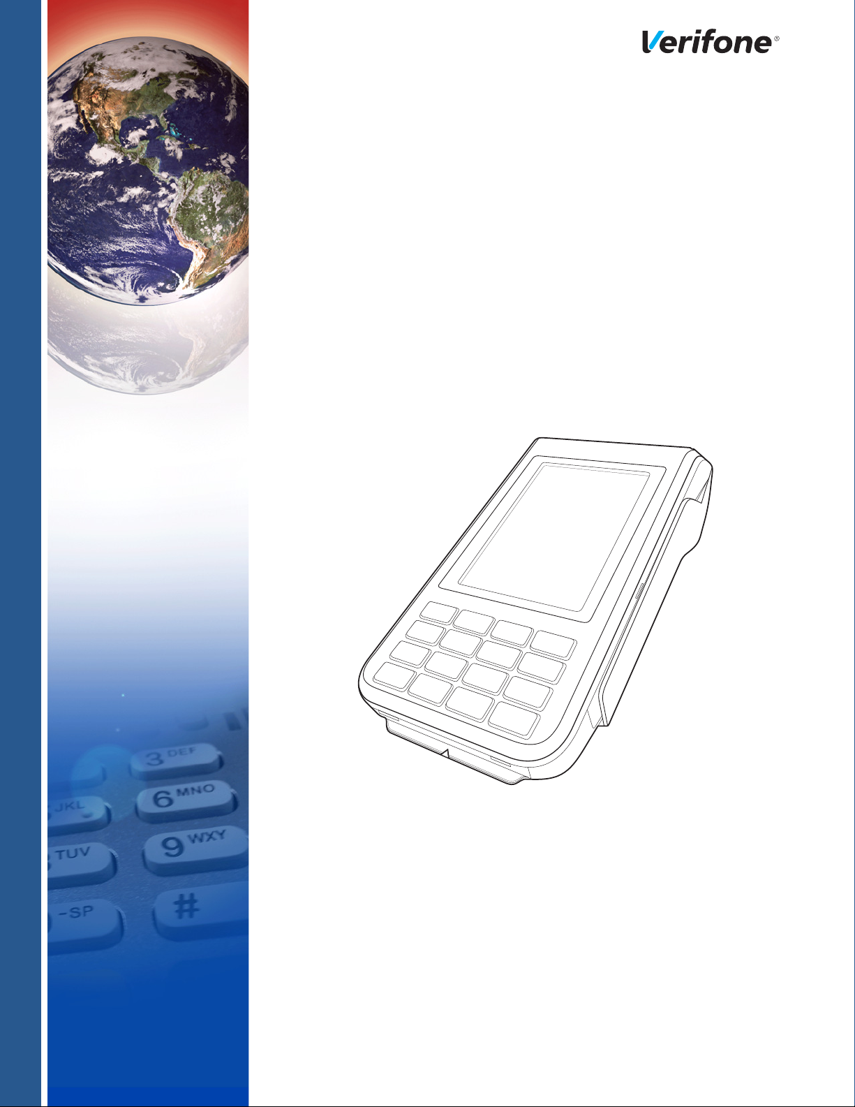
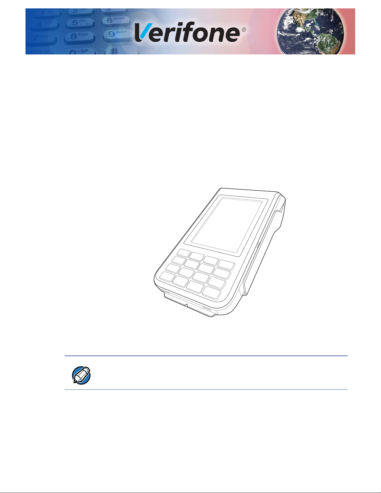
C680 features a color screen display, fast processor, abundant memory, and PCI
4.0 security.
It is a portable, battery-powered device designed to fit comfortably during
handheld consumer-facing applications. It features a 3.5” TFT LCD display and
spill-resistant keypad. It supports the GPRS or 3G communications technology.
CHAPTER 1
NOTE
Figure 1 C680 Terminal
Verifone ships variants of this terminal for different markets. Your terminal may
have a different configuration.
C680 INSTALLATION GUIDE 9
Page 10

TERMINAL OVERVIEW
Features and Benefits
Features and
Benefits
Exceptional Ease of
Use
Performance and
Durability
This terminal provides the right combination of features and functions including a
triple-track magnetic stripe card reader, smart card reader, color screen display,
and a quiet yet fast internal thermal printer (ITP).
• Lightweight, tapered design, compact, stylish and the ergonomic balance
allows convenient terminal hand-off to the consumer for PIN entry or other
input.
• 3.5” TFT LCD display for boundless application possibilities and easy
readability under various lighting conditions.
• keypad provides tactile response to simplify usage and minimize finger slips.
• 40 mm diameter paper roll support with a trouble-free, drop-in, “clam shell”
loading and dual tear bar that allow receipts to be torn in any direction.
• Quiet and fast integrated thermal printer.
• Vertical magnetic stripe card reader with an extended blade for optimal card
reading.
• Fast transactions due to powerful 400 MHz ARM11 processor.
• High-capacity 3.7 V, 2450 mAh Li-ion battery.
Security
Communication
Technology
• Base for drop-and-go charging.
• Rounded corners and drop resistant to 3 feet on concrete floor to minimize
breakage.
• 192 MB of memory.
• PCI PED 4.0 approved for debit and other PIN-based transactions.
• EMV Level 1 Type Approval.
• Tamper-resistant construction, SSL protocols, and VeriShield file
authentication.
• C680 GPRS/3G: Long-range wireless payment for retailers that have no physical
location limitations.
10 C680 INSTALLATION GUIDE
Page 11

Setup
CAUTION
CHAPTER 2
This chapter describes the terminal setup procedures for:
• Terminal Location
• Inside the Shipping Carton
• Terminal Features
• Installing the SIM/SAM/Micro-SD Cards
• Connection Ports
• Installing the Paper Roll
• Power Supply
• Using the Battery
• Battery Behavior (No Power Pack)
• Charging the Battery
Terminal
Location
Ease of Use
Environmental
Factors
• Conducting Smart Card Transactions
• Using the Magnetic Card Reader
• Conducting a Contactless Transaction
Use the following guidelines when selecting a location for the terminal.
• Select a location convenient for both merchant and cardholder.
• Select a flat support surface, such as a countertop or table.
• Select a location near a power outlet, ECR, or computer connected to the
terminal. Do not string cables or cords across a walkway for safety.
• Do not use where there is high heat, dust, humidity, moisture, or caustic
chemicals or oils.
• Keep away from direct sunlight and anything that radiates heat, such as a
stove or motor.
• Do not use outdoors.
This unit is not waterproof or dustproof and is intended for indoor use only. Any
damage to the terminal from exposure to rain or dust may void any warranty.
C680 INSTALLATION GUIDE 11
Page 12

SETUP
WARNING
Inside the Shipping Carton
Electrical
Considerations
Contactless
Considerations
PIN Protection
Measures
• Avoid using the unit during electrical storms.
• Avoid locations near electrical appliances or other devices that cause
excessive voltage fluctuations or emit electrical noise (for example, air
conditioners, electric motors, neon signs, high-frequency or magnetic security
devices, or computer equipment).
• Do not use near water or in moist conditions.
• Disconnect the device from its POS terminal before cleaning.
Do not use near water, including a bathtub, wash bowl, kitchen sink or laundry
tub, in a wet basement, or near a swimming pool to avoid shock or damage.
Avoid having metallic objects in proximity of the contactless antenna. If you need
to mount the terminal to vertical or inclined surfaces, use a flat, non-metallic
mounting plate.
The C680 is a handover device. Always exercise extreme caution when
conducting transactions, specially during PIN entry.
• Hand the terminal directly to the cardholder for PIN entry.
Inside the
Shipping Carton
Unpacking the
Shipping Carton
• Encourage the cardholder to hold the terminal close to avoid others from
seeing the information being entered.
Open the shipping carton and carefully inspect its contents for possible tampering
or shipping damage. The terminal is a secure product. Tampering causes it to
cease to function or to operate in an unsecured manner.
To unpack the shipping carton:
1 Remove and inspect the following items:
• Terminal
• Power pack
• Paper roll
12 C680 INSTALLATION GUIDE
Figure 2 Items Inside the Box
Page 13

Terminal Features
CAUTION
TOUCHSCREEN
DISPLAY
MAGNETIC
CARD READER
SMARTCARD
READER
TELEPHPONE-STYLE
KEYPAD
THERMAL
PRINTER
2 Remove all plastic wrapping from the terminal and other components.
3 Remove the clear protective film from the LCD screen.
4 Save the shipping carton and packing material for future repacking or moving
the terminal.
Do not a unit that has been damaged or tampered with. The terminal comes
equipped with tamper-evident labels. If a label or component appears damaged,
please notify the shipping company and your Verifone representative or service
provider immediately.
SETUP
Terminal
Features
Familiarize yourself with the terminal features before continuing with the
installation process:
Figure 3 C680 Terminal Features
The unit offers the following features:
• A 3.5” touch screen, TFT LCD display.
• A set of keys that include:
a A 12-key, telephone-style keypad (keypads may vary in style).
b Three color-coded function keys below the keypad (from left to right:
CANCEL, CLEAR, ENTER).
• A magnetic card reader, built into the right side. An icon illustrates the proper
card direction, with the magnetic stripe down and facing inward, toward the
keypad.
NSTALLATION GUIDE 13
C680 I
Page 14

SETUP
A
B
A
B
Installing the SIM/SAM/Micro-SD Cards
• An internal thermal printer at the top front of the terminal.
• A smart card reader, built into the bottom of the terminal. An icon indicates the
• A SAM (Security Access Module) compartment, built into the bottom of the
proper card position and insertion point.
terminal inside the back compartment.
Installing the
SIM/SAM/Micro-
SD Cards
To Install or Replace a
SIM Card
You may need to install or replace a GSM SIM (Subscriber Identity Module) card,
one or two SAM (Security Access Module) cards, or a micro-SD card.
1
Ensure that the terminal is turned off.
2 Place the terminal upside down on a soft, clean surface to protect the lens
from scratches.
3 Gently push the compartment cover’s locking mechanish to release. Lift and
remove the cover.
14 C680 INSTALLATION GUIDE
Figure 4 Remove Terminal Back Cover
Lift the battery pack.
4
5 Remove the card slot cover by pushing the movable side of of the terminal
with your finger or by using a screw driver to release.
KCOL
NEPO
Figure 5 Remove Card Slot Cover
Page 15

Installing the SIM/SAM/Micro-SD Cards
OPEN
LOCK
OPEN
LOCK
OPEN
LOCK
OPEN
LOCK
6 With the gold contacts facing down, insert the SIM/SAM card into the
cardholder.
Figure 6 SIM/SAM Card Installation
For micro-SD card, slide down the card slot cover to open. Insert the SD card
facing down and slide back the slot cover to lock.
SETUP
Figure 7 SD Card Installation
Return the card card slot cover.
7
8 Return the battery pack to its original position.
9 Close and screw the back compartment cover.
NSTALLATION GUIDE 15
C680 I
Page 16

SETUP
4 PIN WIRE
Connection Ports
Connection
Ports
Cabling
Connections
The terminal has one primary micro-USB port on the side used for power and
download.
There is another micro-USB connector USB Host located at the back of the
terminal for peripheral connection. Powered RS-232 is supported via RJ11 for
modem connection, and via a 4-pin connector debug and OS download.
Figure 8 Connection Ports
The following are cabling scenarios on your unit:
1 Dedicated Micro-USB Device Port Connection
Dedicated Micro-
USB Device Port
Connection
2 Micro-USB Host Port Connection
.
3 Powered RS-232/4-Pin Connection.
4 Powered RS-232/RJ11 Connection
The micro-USB Device port on the side of the unit is dedicated to download/power
charging. Insert the micro-USB plug end of the Host connector cable to the microUSB port on the terminal to connect.
Figure 9 Dedicated Micro USB Device Port
Micro-USB Host
Port Connection
16 C680 INSTALLATION GUIDE
The micro-USB Host port on the back of the unit is used for connecting peripheral
devices. Insert the micro-USB plug end of the pheriperal cord to the micro-USB
port on the back of the terminal to connect.
Page 17

SETUP
CAUTION
A
B
C D
Installing the Paper Roll
Powered RS-232/4-
Pin Connection
Powered RS-232/ RJ11 Connection
Installing the
Paper Roll
The powered RS-232/4-pin connector on the back of the terminal is mainly
designed for 1D/2D barcode scanner.
Similar to 4-pin connection, powered RS-232/RJ11 connector on the back of the
terminal is designed for 1D/2D barcode scanner.
A fast, quiet thermal printer is built into the terminal. Before you can process
transactions that require a receipt or record, you must install a roll of thermalsensitive paper in the printer.
The ITP uses a roll of 40 mm single-ply, thermal-sensitive paper. A pink out-ofpaper indicator line appears on the edge of the paper approximately 18 inches
before the end of the roll.
After this line appears, there is enough paper remaining on the roll to conclude at
least one transaction.
Poor-quality paper can jam the printer and create excessive paper dust. To order
high-quality Verifone paper, refer to
Store thermal paper in a dry, dark area and handle carefully. Impact, friction,
temperature, humidity, and oils affect the color and storage characteristics of the
paper. Never load a roll of paper with folds, wrinkles, tears, or holes at the edges
in the print area.
Accessories and Documentation.
To Install a Paper Roll
Gently pull the latch located on top of the terminal to unlock the paper roll
1
cover.
Figure 10 Paper Roll Installation
2
Lift the printer cover up to open.
3 Remove any partial roll of paper in the printer tray.
4 Loosen the glued leading edge of the new roll of paper or remove the
protective strip, if applicable. Unwind the paper roll past any glue residue.
5 Hold the roll so the paper feeds from the bottom of the roll.
6 Drop the paper roll into the printer tray.
7 Pull paper up past the glue residue on the paper roll.
NSTALLATION GUIDE 17
C680 I
Page 18

SETUP
CAUTION
WARNING
NOTE
NOTE
Power Supply
8 Close the paper roll cover by gently pressing directly on the cover until it clicks
shut, allowing a small amount of paper past the glue residue to extend outside
the printer door.
To prevent damaging the print roller, always gently press down on the paper roll
cover to close it.
9 Tear the paper off against the serrated plastic strip in the printer.
Power Supply
After establishing all necessary connections, connect the power pack to the
terminal and into a wall outlet or powered surge protector to charge the battery for
six hours or until fully charged.
Do not plug the power pack into an outdoor outlet or operate the terminal
outdoors. During a transaction, disconnecting the power by removing the battery
or unplugging the terminal from a wall power while at very low battery charge may
cause transaction data files not yet stored in the terminal memory to be lost.
Each C680 terminal comes with power supply (VPN PWRXXX-001-XX-A) used to
connect the terminal directly to a power outlet and to charge the battery. The C680
unit comes with a universal input power pack capable of operating from voltages
of 100 V to 240 V AC.
To protect against possible damage caused by lightning strikes and electrical
surges, consider installing a power surge protector.
Once it loads the application, the terminal starts the initial Verifone copyright
screen and displays a unique copyright screen. If there is no available application
in the terminal,
copyright screen.
DOWNLOAD NEEDED appears on screen after the initial Verifone
18 C680 INSTALLATION GUIDE
Using the
Battery
The C680 terminal uses a single cell Li-ion battery (see Accessories and
Documentation
both overcharging and undercharging (a fault condition in which the battery level
goes well below the minimum acceptable charge and the battery becomes
unusable).
The C680 terminal will only operate when the battery is installed.
for ordering information). The internal logic of the battery prevents
Page 19

SETUP
NOTE
NOTE
Battery Behavior (No Power Pack)
Battery Features
The following are features of the battery:
• Single cell Li-ion 2450 mAH battery pack.
• A safety circuit that:
• Prevents cell damage from overcharge, over-discharge, or overheating.
• Activates when the battery is left in an unused terminal for extended
periods.
• C680 battery pack (PN BPK260-001-01-A) not customer changeable and
therefore should not be disconnected and removed.
• Li-ion batteries are not affected by shallow charging. Furthermore, when the
terminal has no external power source or battery, the coin cell battery
provides power to the security circuit.
• Disconnecting and removing the battery, as well as unplugging the terminal
power pack, reduce the life of the coin cell battery, which does not recharge
and must be replaced if drained.
• Conserve battery power by turning the C680 terminal off when not in use.
Keep the Li-ion battery inserted in the terminal and power up the terminal
periodically to check the battery charge. Do not let the battery charge fall
below 10% for extended periods of time as this may permanently diminish the
battery capacity. Recharge the battery by attaching the micro-USB end of the
power pack to the terminal and plugging the other end of the power pack into
a wall outlet.
Battery Behavior
(No Power Pack)
Manual Startup
The terminal shifts to power pack mode and starts up automatically when the
C680 is connected to a non-battery power source, regardless of the battery
charge state.
Hold the green key down for about 4 seconds until the terminal displays the
startup screen.
The 4-second power-up delay prevents terminal startup if the green key is
accidentally held down. The time required to hold the green key down to power up
the terminal is configurable. For more information, see C680 Reference Guide –
VPN
DOC269-004-EN).
The Verifone copyright screen starts and displays a unique copyright screen once
the terminal loads an application. However,
screen after the initial Verifone copyright screen if there is no available application
in the terminal..
DOWNLOAD NEEDED appears on
NSTALLATION GUIDE 19
C680 I
Page 20

SETUP
NOTE
NOTE
WARNING
Charging the Battery
Manual Shutdown
Charging the
Battery
Hold the red key down for about 4 seconds until the terminal displays the
shutdown verification screen. Keep holding the red key until the C680 terminal
shuts down.
• The 4-second shutdown delay that prevents terminal shutdown if the red key
is accidentally held down. The time required to hold the red key down to shut
down the terminal is configurable (for more information, see the C680
Reference Guide – VPN VPN
DOC269-004-EN).
• The screen is blank when the terminal has no power.
The battery has a safety circuit to protect the Li-ion cells from overcharging and
over-discharging. If the battery is over-discharged, the safety circuit shuts down
the battery. The battery must then be recharged to restore operation.
The terminal automatically shuts off when the battery reaches the critically low
charge state. If this occurs, the battery must be recharged for a minimum of 1/2
hour before it can power the terminal. It may take several recharge attempts to
reset the safety circuit when charging a battery that has been discharged below
this critical state.
Battery Life
Conducting
Smart Card
Transactions
To Conduct a Smart
Card Transaction
Charging and discharging the battery hundreds of times will wear out the battery.
Significantly reduced operating times indicate the need for battery replacement
Accessories and Documentation for ordering information).
(see
Do not dispose of batteries in a fire. Li-ion batteries must be recycled
or disposed of properly. Do not dispose of Li-ion batteries in municipal
waste sites.
The smart card transaction procedure may vary from one application to another.
Verify the procedure with your application provider before performing a smart card
transaction.
Position a smart card with the contacts facing upward.
1
20 C680 INSTALLATION GUIDE
Figure 11 Smart Card Transaction
Page 21

Using the Magnetic Card Reader
CAUTION
2 Insert the smart card into the smart card reader slot in a smooth, continuous
motion until it seats firmly.
3 Remove the card only when the application indicates the transaction is
complete.
Do not remove the smart card in the card reader until the transaction is complete.
Premature card removal will invalidate the transaction.
SETUP
Using the
Magnetic Card
Reader
To Conduct a Credit
or Debit Card
Transaction
The C680 terminal supports credit/debit card transactions.
Figure 12 Credit/Debit Card Transaction
Position a magnetic card with the stripe in the card reader and facing inward,
1
toward the keypad.
2 To ensure a proper read of the magnetic swipe card, the user should insert the
magnetic card from the top of the unit, as shown in the following illustration.
3 Swipe the card through the magnetic card reader.
Conducting a
Contactless
Transaction
The C680 terminal supports contactless transactions through an integrated
contactless module. The terminal only becomes active for contactless smart card
transactions when initialized by an application.
Figure 13 Conducting Contactless Transactions
NSTALLATION GUIDE 21
C680 I
Page 22

SETUP
NOTE
Periodic Inspection
To Conduct a
Contactless
Transaction
Periodic
Inspection
Gently tap the card onto or hold the card (within 4 cm) against the surface of
1
the display.
2 An activated LED visual on the display accompanied by a short beeping sound
indicates a successful transaction.
Periodically inspect the terminal for possible tampering. Signs of tampering
include:
• Wires protruding out of the device.
• Foreign objects inserted into the smart card or mag stripe slot.
• Signs of damage to the tamper-evident labels.
• Warning message on the device display.
If any device is found in tamper state, please remove it from service immediately.
Keep it available for potential forensics investigation and notify your company
security officer and your local Verifone representative or service provider. For
contacting Verifone, refer to
Verifone Service and Support.
22 C680 INSTALLATION GUIDE
Page 23

Specifications and Maintenance
This chapter discusses power requirements, dimensions, other specifications of
the terminal, and maintenance.
CHAPTER 3
Power Pack
Temperature
External
Dimensions
Maintenance
5 VDC 2.2 A (11W), compliant with ERP/EUP Stage 2.
a Input rated: 100-240 VAC, 50/60 Hz
b Output rated: 5 VDC 2.2 A
Operating Environment
• Temperature: 0
°
C to 40° C (23°F to 104° F)
• Relative humidity: 5% to 95% RH non-condensing
Non-Operating Environment
• temperature: -20
°
C to 50° C (-4°F to 122° F)
• Relative humidity: 5% to 95% RH non-condensing
• Length: 172.86 mm (6.8 in)
• Width: 82.25 mm (3.2 in)
• Depth: 59.3 mm (2.3 in)
• Weight: 352 g
The C680 terminal and base have no user-serviceable parts.
Cleaning the
Termi nal
CAUTION
To clean the terminal and base, use a clean cloth slightly dampened with water
and a drop or two of mild soap. For stubborn stains, use alcohol or an alcoholbased cleaner.
Never use thinner, trichloroethylene, or ketone-based solvents. These may cause
deterioration of plastic or rubber parts. Do not spray cleaners or other solutions
directly onto the keypad or terminal display.
C680 INSTALLATION GUIDE 23
Page 24

SPECIFICATIONS AND MAINTENANCE
CAUTION
Maintenance
Terminal Contacts
Smart Card Reader
Gently swab the contacts with alcohol or contact cleaner to remove the dirt. It is
important that the exposed contacts of the battery stay clean and unbent.
Avoid touching the contacts of the battery and the recessed area on the terminal.
Finger oils tarnish contacts, causing bad connections. When operating on battery
power and experiencing a high occurrence of bad or incomplete data transfers,
clean the contacts.
Do not attempt to clean the smart card reader. Doing so may void any warranty.
For smart card reader service, contact your Verifone distributor or service
provider.
24 C680 INSTALLATION GUIDE
Page 25

Verifone Service and Support
NOTE
For terminal problems, contact your local Verifone representative or service
provider. For product service and repair information:
• USA – Verifone Service and Support Group, 1-800-Verifone (837-4366),
Monday - Friday, 8 A.M. - 8 P.M., Eastern time
• International – Contact your Verifone representative
CHAPTER 4
Returning a
Terminal for
Service
To Return a Terminal
for Service
Before returning a terminal or base to Verifone, you must obtain an MRA number.
The following procedure describes how to return one or more terminals or bases
for repair or replacement (U.S. customers only).
Customers outside the United States are advised to contact their local Verifone
representative for assistance regarding service, return, or replacement of
terminals or batteries.
1 Get the following information from the printed labels on the bottom of each
C680 terminal or base to be returned:
• Product ID, including the model and part number. For example, “C680”
and “MXXX-XXX-XX-XXX-2.”
• Serial number (S/N nnn-nnn-nnn)
2 Obtain the MRA number(s) by completing one of the following:
a Call Verifone toll-free within the United States at 1-800-Verifone and follow
the automated menu options.
• Select the MRA option from the automated message. The MRA
department is open Monday to Friday, 8 A.M.–8 P.M., Eastern Time.
• Give the MRA representative the information you gathered in Step 1.
If the list of serial numbers is long, you can fax the list, along with the
information gathered in Step 1, to the MRA department at 727-9534172 (U.S.).
b Address a fax to “Verifone MRA Dept.” with the model and part number(s)
• Include a telephone number where you can be reached and your fax
number.
c Complete the Inquiry Contact Form at http://www.verifone.com/aboutus/
contact/contact_form.cfm.
C680 INSTALLATION GUIDE 25
Page 26

VERIFONE SERVICE AND SUPPORT
NOTE
Accessories and Documentation
• Address the Subject box with to “Verifone MRA Dept.”
• Reference the model and part number in the Note box.
One MRA number must be issued for each terminal you return to Verifone, even if
you are returning several of the same model.
3 Describe the problem(s).
4 Provide the shipping address where the repaired or replacement unit must be
returned.
5 Keep a record of the following items:
• Assigned MRA number(s).
• Verifone serial number assigned to the terminal or base you are returning
for service or repair (terminal serial numbers are located on the bottom of
the unit.
Accessories and
Documentation
Power Pack
Printer Paper
• Shipping documentation, such as air bill numbers used to trace the
shipment.
• Model(s) returned (model numbers are located on the Verifone label on the
bottom of the terminal).
Verifone produces the following accessories and documentation for the
terminal. When ordering, please refer to the part number in the left column.
• Verifone online store at www.store.verifone.com
• USA – Verifone Customer Development Center, 800-Verifone (837-4366),
Monday - Friday, 7 A.M. - 8 P.M., Eastern time
• International – Contact your Verifone representative
Contact your local Verifone distributor to determine which power pack fits your
needs.
VPN PWR265-001-01-A DC Power Pack (Universal)
VPN PPR268-001-01-A 40 mm (1.57 in) diameter, 57 mm (2.24 in) wide
Verifone Cleaning
Micro-USB Cable
26 C680 INSTALLATION GUIDE
Kit
VPN 02746-01 Cleaning Kit
VPN SUB265-001-01-A Micro-USB service dongle
Page 27

Documentation
VERIFONE SERVICE AND SUPPORT
Accessories and Documentation
C680 Certifications and Regulations Sheet
C680 Quick Installation Guide
C680 Reference Guide
Verix eVo Volume I: Operating System Programming
Manual
Verix eVo Volume II: Operating System and
Communications Programmers Manual
DOC268-061-EN
DOC268-062-EN
DOC268-064-EN
DOC00301
DOC00302
NSTALLATION GUIDE 27
C680 I
Page 28

VERIFONE SERVICE AND SUPPORT
Accessories and Documentation
28 C680 INSTALLATION GUIDE
Page 29

CHAPTER 5
NOTE
CAUTION
Troubleshooting
Guidelines
The troubleshooting guidelines provided in the following section are included to
help you install and successfully configure the device. Typical examples of
malfunction you may encounter while operating the device and steps you can take
to resolve them are listed in this chapter.
If the problem persists even after performing the outlined guidelines or if the
problem is not described below, contact your local Verifone representative for
assistance.
The device comes equipped with tamper-evident labels. It does not come with
user serviceable parts. Do not, under any circumstance, attempt to disassemble
the device. Perform only the adjustments or repairs specified in this guide. For all
other services, contact your local Verifone service provider. Service conducted by
parties other than authorized Verifone representatives may void any warranty.
Use only a Verifone-supplied power pack. Using an incorrectly-rated power
supply may damage the terminal or cause it not to work as specified. Before
troubleshooting, ensure that the power supply being used to power the terminal
matches the requirements specified on the bottom of the terminal. (See
Specifications and Maintenance, for detailed power supply specifications.) Obtain
the appropriately rated power supply before continuing with troubleshooting.
Terminal Does
Not Start
Does Not Show
Correct/
Readable Info
If the terminal does not start:
• Ensure that the battery charge state is not below the critically low level.
• Recharge or replace the battery.
• Ensure that you pressed the green ENTER/ON key for approximately 4
seconds, until the unit lights up.
If the terminal does not show the correct/readable information:
• Recharge or replace the battery.
• Connect the terminal into a known-good power supply (if you have one) to see
if this clears the problem.
• If the problem persists, contact your local Verifone representative for
assistance.
C680 INSTALLATION GUIDE 29
Page 30

TROUBLESHOOTING GUIDELINES
Battery Does Not Charge
Battery Does Not
Charge
The terminal’s battery must initially receive a full charge to ensure proper
operation.
• Allow the terminal to remain connected to the power pack for 6 hours to
ensure the battery receives a full charge.
• Li-ion batteries are not affected by shallow charging. Furthermore, when the
terminal has no external power source or battery the coin cell battery provides
power to the security circuit.
• Uninstalling the battery and unplugging the terminal power pack reduce the life
of the coin cell battery, which does not recharge and must be replaced if
drained.
• Conserve battery power by turning the terminal off when not in use. Keep the
Li-ion battery inserted in the terminal and power up the terminal periodically to
check the battery charge. Do not let the battery charge fall below 10% for
extended periods of time as this may permanently diminish the battery
capacity. Recharge the battery by attaching USB end of the power pack to the
terminal and plugging the other end of the power pack into a wall outlet.
• The terminal automatically shuts off when the battery reaches the critically low
charge state. If this occurs, the battery must recharge a minimum of 1/2 hour
before it can power the terminal. It may take several recharge attempts to
reset the safety circuit when charging a battery that has been discharged
below this critical state.
Blank Display
Printer Does Not
Print
When the terminal display screen does not show the correct or clearly readable
information:
• The battery pack may not be connected properly. Remove and reinstall the
battery pack.
• Check terminal power connection.
• Remove and reapply power to the terminal.
• If the problem persists, contact your local Verifone service provider.
If the printer does not work properly:
• Make sure the battery is properly installed in the terminal. The printer will not
print if there is no battery in the terminal.
• Check battery status or terminal power connection. The printer will not print if
there is an insufficient charge remaining in the battery to complete the print
operation.
• Check if the printer is out of paper (slow red blinking light) and that the roll is
properly installed. Open the paper roll cover and install a new roll of printer
paper or ensure that the roll is feeding correctly. A solid red indicator light
indicates a printer error.
30 C680 INSTALLATION GUIDE
• Verify that the printer door is properly latched.
Page 31

TROUBLESHOOTING GUIDELINES
WARNING
Printer Paper Jam
• If the problem persists, contact your Verifone distributor or service provider.
Printer Paper
Jam
Keypad Does
Not Respond
If paper jams inside the printer:
• Press the button at the bottom of the terminal to unlatch the paper roll cover,
then open the cover.
• Remove the damaged paper from the paper roll and clear the feed
mechanism.
• Install a roll of printer paper, as described in Installing the Paper Roll.
• If the problem persists, it may be due to poor paper quality. Install a new roll of
higher-quality paper.
Poor-quality paper may jam the printer. To order high-quality Verifone paper, refer
to
Accessories and Documentation.
If the keypad does not respond properly:
• Check the terminal display. If it displays the wrong character or nothing at all
when you press a key, follow the steps outlined in
Process
.
Transactions Fail to
• If pressing a function key does not perform the expected action, refer to the
user documentation for that application to ensure you are entering data
correctly.
Transactions
Fail to Process
• If the problem persists, contact your local Verifone representative.
There are several reasons why the terminal may not be processing transactions.
Use the following steps to troubleshoot failures.
Check the Magnetic Card Reader
Perform a test transaction using one or more different magnetic stripe cards to
•
ensure the problem is not a defective card.
• Ensure that you are swiping cards properly. With the C680 card reader, the
black magnetic stripe on the card should face down and inward, toward the
keypad and must be inserted from the top of the terminal.
• Process a transaction manually, using the keypad instead of the card reader. If
the manual transaction works, the problem may be a defective card reader.
• Contact your Verifone distributor or service provider.
• If the manual transaction does not work, proceed to Check the Signal
Strength
Check the Smart Card Reader
.
• Perform a test transaction using several different smart cards to ensure the
problem is not a defective card.
NSTALLATION GUIDE 31
C680 I
Page 32

TROUBLESHOOTING GUIDELINES
Transactions Fail to Process
• Ensure that the card is inserted correctly and that the card is not removed
prematurely.
• Contact your Verifone distributor or service provider.
• If the manual transaction does not work, proceed to Check the Signal
Strength
Check the Signal Strength
.
• On-screen signal-strength indicator displays at least one bar to indicate
connectivity to radio network.
• Ensure that the radio has been activated by your service provider.
.
32 C680 INSTALLATION GUIDE
Page 33

FCC Regulations:
This device complies with part 15 of the FCC Rules. Operation is subject to the following two conditions: (1)
This device may not cause harmful interference, and (2) this device must accept any interference received,
including interference that may cause undesired operation.
Changes or modifications not expressly approved by the party responsible for compliance could void the user‘s
authority to operate the equipment.
****************************************************************************************************************************
This equipment has been tested and found to comply with the limits for a Class B digital device, pursuant to
part 15 of the FCC Rules. These limits are designed to provide reasonable protection against harmful
interference in a residential installation. This equipment generates, uses and can radiate radio frequency
energy and, if not installed and used in accordance with the instructions, may cause harmful interference to
radio communications. However, there is no guarantee that interference will not occur in a particular installation.
If this equipment does cause harmful interference to radio or television reception, which can be determined by
turning the equipment off and on, the user is encouraged to try to correct the interference by one or more of the
following measures:
—Reorient or relocate the receiving antenna.
—Increase the separation between the equipment and receiver.
—Connect the equipment into an outlet on a circuit different from that to which the receiver is connected.
—Consult the dealer or an experienced radio/TV technician for help.
Page 34

Verifone, Inc.
1-800-Verifone
www.verifone.com
C680
Installation Guide
Verifone Part Number DOC268-063-EN-A, Revision A
 Loading...