

Page 1
O3350 IG 19496 Book.book Page 1 Wednesday, April 5, 2000 10:30 PM
Omni 3350
Installation Guide
Page 2

O3350 IG 19496 Book.book Page 2 Wednesday, April 5, 2000 10:30 PM
Lithium Battery Caution
The Random Access Memory (RAM) contents in th e Omni 3350
terminal are protected by a lithium battery. Do not, under any
circumstances, attempt to replace this battery. Failure to comply may
invalidate the product warranty.
Document Title: Omni 3350 Installation Guide
VeriFone Part Number 22131, Revision B
Copyright © 2000 VeriFone
All rights reserved.
No part of this publication may be copied, distributed, stored in a
retrieval system, translated into any human or computer language,
transmitted, in any form or by any means, without the prior written
consent of VeriFo ne .
VeriFone and Omni are register ed trademarks of VeriFone.
Any other brand names and trademarks appearing in this guide are the
property of their respective holders.
Comments or suggestions on how to improve this document can be
sent to Tell_us_more@verifone.com.
Page 3

O3350 IG 19496 Book.book Page 3 Wednesday, April 5, 2000 10:30 PM
Omni 3350 Installation Guide
Table of Contents
Install the Omni 3350. . . . . . . . . . . . . . . . . . . . . . . . . . . . . . . . . . . . . . .5
Step 1: Select a Location for the Terminal . . . . . . . . . . . . . . . . . . .5
Step 2: Unpack the Shipping Carton . . . . . . . . . . . . . . . . . . . . . . .6
Step 3: Examine Terminal Features . . . . . . . . . . . . . . . . . . . . . . . .7
Step 4: Connect the Terminal to a Telephone Line . . . . . . . . . . .11
Step 5: Connect the Terminal Power Pack . . . . . . . . . . . . . . . . . .13
Step 6: Install a Paper Roll in the Printer . . . . . . . . . . . . . . . . . . .15
Step 7: Install/Replace MSAM Cards . . . . . . . . . . . . . . . . . . . . .18
Step 8: Use the Primary Smart Card Reader . . . . . . . . . . . . . . . .22
Step 9: Use the Magnetic Card Reader . . . . . . . . . . . . . . . . . . . .23
Connect Optional Device(s). . . . . . . . . . . . . . . . . . . . . . . . . . . . . . . . .23
Connect PIN Pad, Smart Card Reader, or Bar Code Wand. . . . . .24
Connect a CR 600 Check Reader . . . . . . . . . . . . . . . . . . . . . . . . .25
Cable Routing. . . . . . . . . . . . . . . . . . . . . . . . . . . . . . . . . . . . . . . . . . . .26
Clean the Terminal and Printer. . . . . . . . . . . . . . . . . . . . . . . . . . . . . . .27
Terminal. . . . . . . . . . . . . . . . . . . . . . . . . . . . . . . . . . . . . . . . . . . . .27
Smart Card Reader . . . . . . . . . . . . . . . . . . . . . . . . . . . . . . . . . . . .27
Printer . . . . . . . . . . . . . . . . . . . . . . . . . . . . . . . . . . . . . . . . . . . . . .28
Printer Troubleshooting . . . . . . . . . . . . . . . . . . . . . . . . . . . . . . . . . . . .28
VeriFone Service and Support . . . . . . . . . . . . . . . . . . . . . . . . . . . . . . .29
Returning a Terminal for Service . . . . . . . . . . . . . . . . . . . . . . . . .30
Specifications . . . . . . . . . . . . . . . . . . . . . . . . . . . . . . . . . . . . . . . . . . . .31
Declaration of Conformity . . . . . . . . . . . . . . . . . . . . . . . . . . . . . . . . . .33
Product Certifications. . . . . . . . . . . . . . . . . . . . . . . . . . . . . . . . . . . . . .34
Accessories and Documentation. . . . . . . . . . . . . . . . . . . . . . . . . . . . . .36
How to Order. . . . . . . . . . . . . . . . . . . . . . . . . . . . . . . . . . . . . . . . .36
Page 4

O3350 IG 19496 Book.book Page 4 Wednesday, April 5, 2000 10:30 PM
Omni 3350 Installation Guide
4
Page 5

O3350 IG 19496 Book.book Page 5 Wednesday, April 5, 2000 10:30 PM
Omni 3350 Installation Guide
Install the Omni 3350
If using the optional swivel base (refer to “Accessories and
Documentation‚” page 36), follow the swivel base’s
instructions before installing your Omni 3350 terminal.
Step 1: Select a Location for the Terminal
When selecting a location, consider these important factors:
Ease of Use
• A location convenient for both merchant and cardholder.
• A flat support surface, such as a countertop or table.
• A location near a power outlet and a telephone/modem
line connection.
Environment
• Do not use the terminal where there is high heat, dust,
humidity, moisture, or caustic chemicals or oils.
• A v oid locations n ear electrical ap pliances o r other devices
that cause excessive voltage fluctuations or emit electrical
noise (for example, air conditioners, electric motors, neon
signs, high-frequency or magnetic security devices, or
computer equipment).
• Keep the terminal away from direct sunlight and anything
that radiates heat, such as a stove or a motor.
Caution: Do not use the terminal outdoors. It is not waterproof
or dustproof, and is for indoor use onl y . Any damage to the unit
from exposure to rain or dust may void your warranty.
5
Page 6
O3350 IG 19496 Book.book Page 6 Wednesday, April 5, 2000 10:30 PM
Omni 3350 Installation Guide
Warning: Due to risk of shock or terminal damage, do not use
the terminal near water, including a bathtub, wash bowl, kitchen
sink or laundry tub, in a wet basement, or near a swimming
pool. Also, avoid using this product during electrical storms.
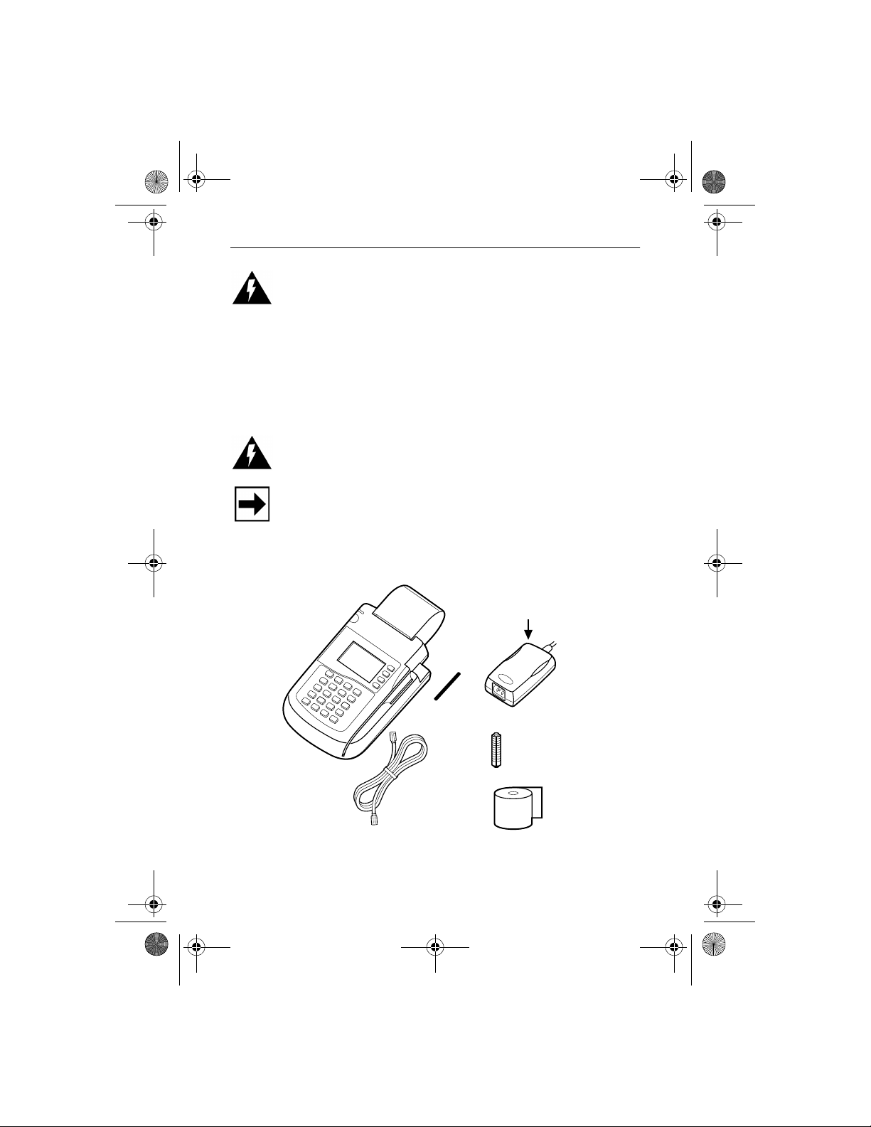
Step 2: Unpack the Shipping Carton
1. Open the shipping carton and carefully inspect its contents
for possible tampering or shipping damage (Figure 1).
Warning: Do not use a terminal that has been damaged or
tampered with.
Note: The Omni 3350 terminal comes equipped with tamperevident labels (one on the case seam, another on a screw hole
on the case bottom). If a label or component appears damaged,
please immediately notify the shipping company and your
VeriFone distributor or service provider.
Power Pack
(cable not included)
Terminal
Smart Card
Reader Cover
Paper Roll
Spindle
Telephone
Line Cord
Printer
Paper
Figure 1 Omni 3350 Product Components
6
Page 7
O3350 IG 19496 Book.book Page 7 Wednesday, April 5, 2000 10:30 PM
Omni 3350 Installation Guide
2. Remove the following items:
• Omni 3350 terminal
• Power pack (for a power cable, contact your supplier)
• T el eph one lin e cord
• Roll of thermal printer paper (in a plastic bag)
• Smart card reader cover (for optional installation)
• Plastic paper roll spindle
Note: The roll of thermal printer paper and the paper roll
spindle may have been installed prior to shipment.
3. Remove all plastic wrapping from the terminal and other
components.
4. Remove the clear protective strip from the display lens.
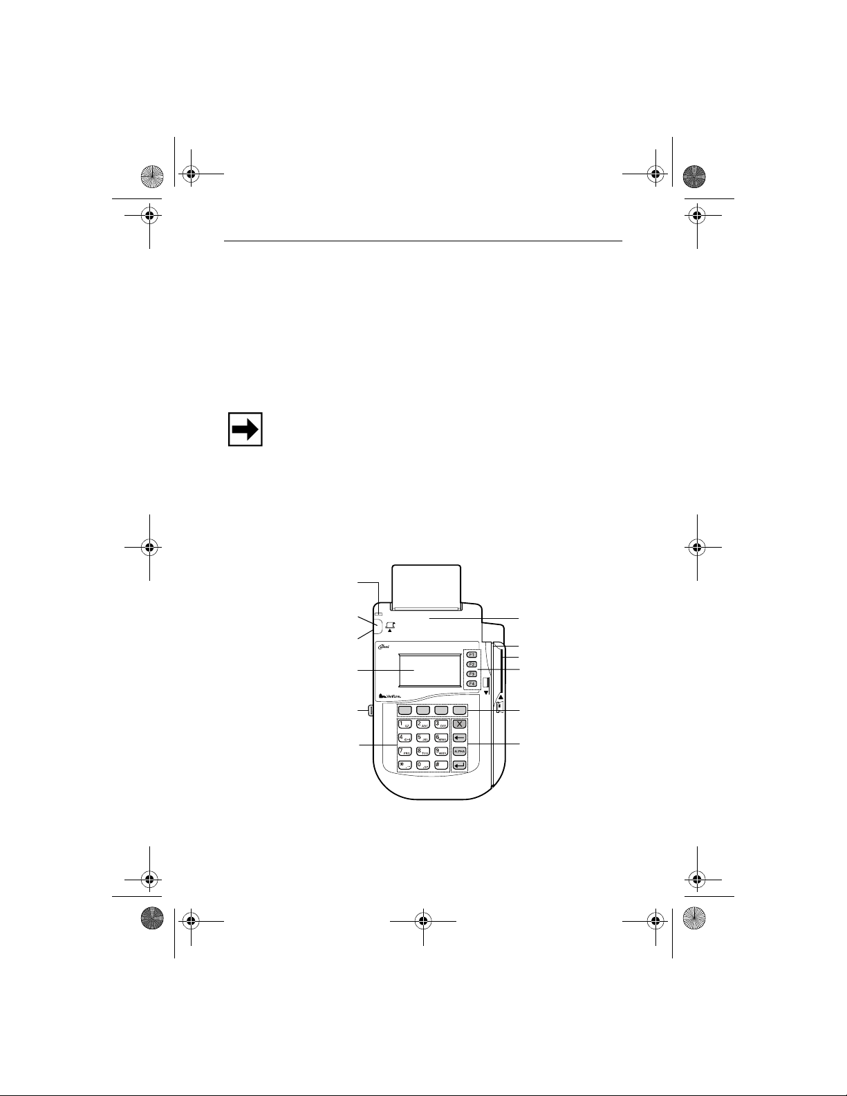
Step 3: Examine Terminal Features
Power-On
LED Indicator
Paper Feed Button
On/Off Switch
Display
SAM Drawer
Telco-Style
Keypad
3350
Figure 2 Omni 3350 Terminal Features
Internal Printer
Magnetic Card Reader
Smart Card Reader
ATM-Style Keys
Programmable
Function Keys
Color-Coded
Function Keys
7
Page 8
O3350 IG 19496 Book.book Page 8 Wednesday, April 5, 2000 10:30 PM
Omni 3350 Installation Guide
General Features
Please notice the following (Figure 2):
•A display screen.
• Three types of keys:
– A 12-key, telephone- style keypad
– Eight function keys (four to the right of the 12-key
keypad, and four above the keypad)
– Four ATM-style keys to the display’s right
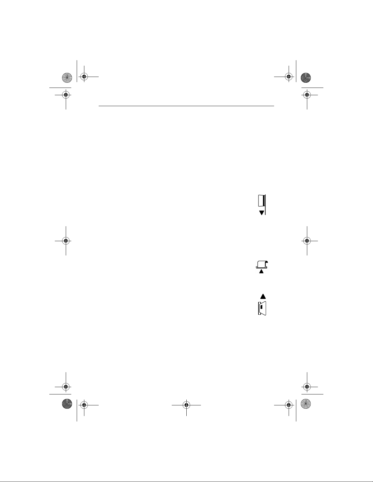
•A magnetic stripe card reader, built into the
right side. The icon at right shows the proper
swipe direction, with the strip outward.
• A green/red indicator LED (Light Emitting Diode). A
steady green light indicates power is on; flashing green
indicates no paper in the printer. A steady red light
indicates a memory problem; flashing red indicates the
terminal is downloading printer-related files.
• An internal printer. The paper feed button
(icon at right) feeds paper through the printer.
•An on/off switch, located on the side, below
the paper feed button.
•A primary smart card reader, built into the
terminal’s right side. A gr aphical icon (shown
at right) indicates the proper card position and
insertion direction, with the chip inward and
down.
8
Page 9
O3350 IG 19496 Book.book Page 9 Wednesday, April 5, 2000 10:30 PM
Omni 3350 Installation Guide
Note: An adhesive-backed, smart card reader cover is
provided for terminals that will not utilize the smart card
reader. To use the cover, simply remove the backing and affix
the cover over the primary smart card reader slot and icon.
Doing so will prevent accumlation of debris in the reader and
reduce customer confusion.
•A SAM (security access module) drawer, built into the
bottom left side of the terminal. The Omni 3350 terminal
contains four micromodule-size SAM (MSAM)
cardholders for supporting multiple stored-value card
programs or other merchant card requirements. In
addition, the drawer itself can hold one standard-size
merchant smart card.
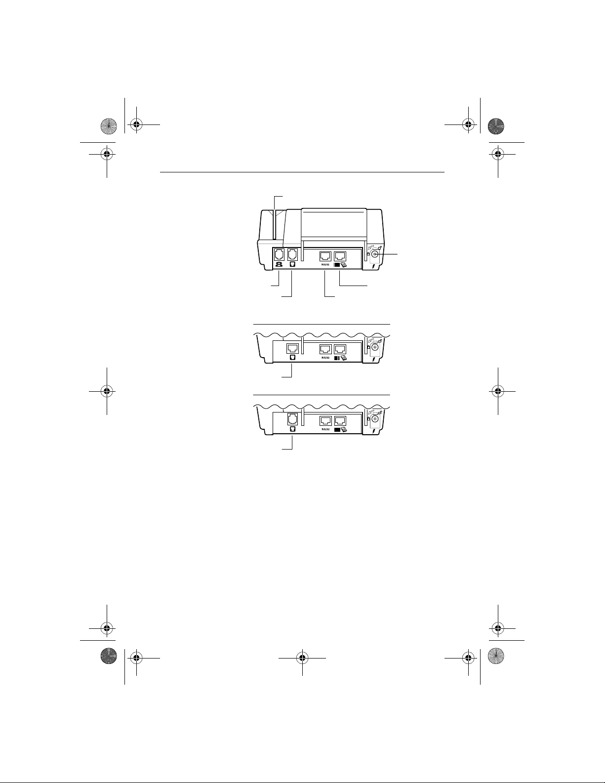
Connection Ports on the Back Panel
Beneath the paper roll holder (Figure 3), you will see one of
the following jack, or port, configurations based on your
terminal’s modem type.
9
Page 10
O3350 IG 19496 Book.book Page 10 Wednesday, April 5, 2000 10:30 PM
Omni 3350 Installation Guide
Card Reader Slot
Power
Port
Telset Port
Telco Port
High-Speed Modem Terminal
ISDN Port
ISDN Modem Terminal
Dial/Leased-Line Port
Dial/Leased-Line Modem Terminal (Canada only)
RS-232
Serial Port
Bar Code /
PINPad Serial Port
Figure 3 Connection Ports
These ports connect the Omni 3350 to a telephone line,
optional devices, and the power supply.
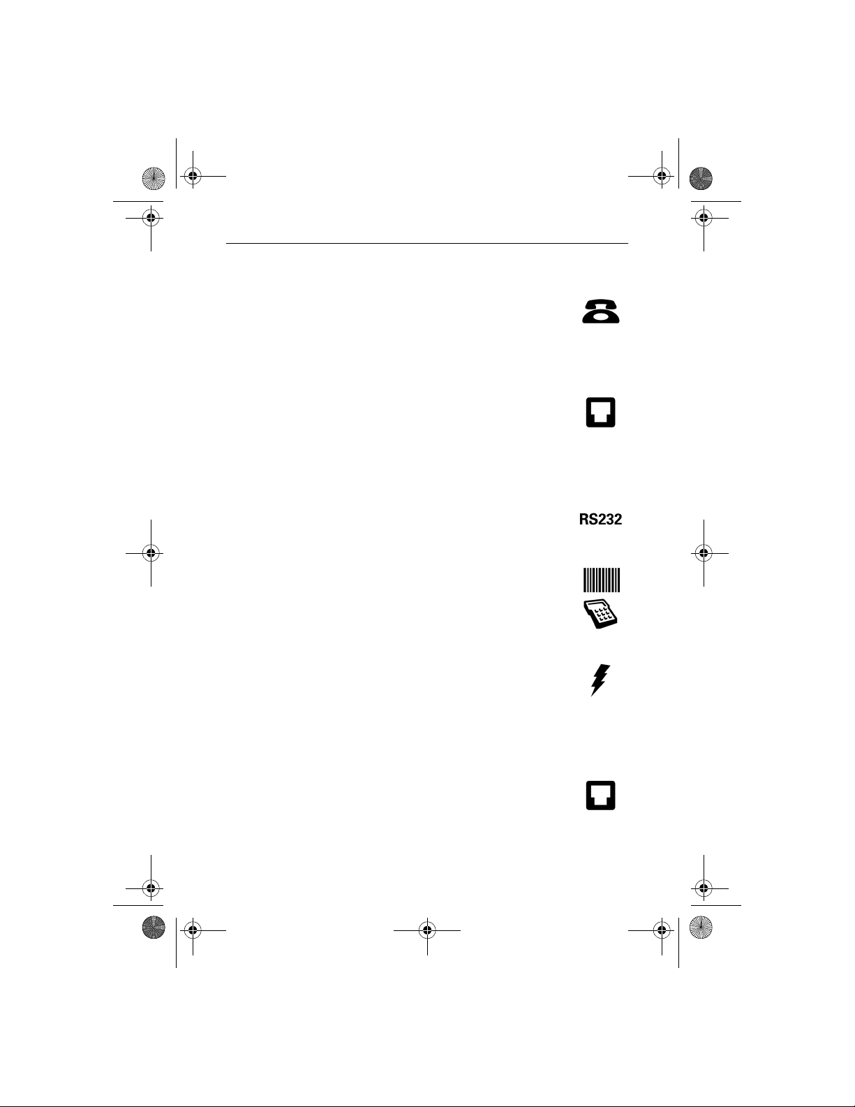
Telephone Line Ports
On the back panel’s far left are one or two modular ports
(based on your terminal’s modem type) for connecting the
terminal to a telephone line.
10
Page 11
O3350 IG 19496 Book.book Page 11 Wednesday, April 5, 2000 10:30 PM
Omni 3350 Installation Guide
Telset Port (High-Speed Modem Terminal only)
The first port is identified by a telephone-shaped
“Telset” icon (shown at right). Use this port to
connect a telephone to the Omni 3350.
Telco, ISDN, Dial/Leased-Line Port
The second port is identified by the icon shown at
right. Use this port to connect the Omni 3350 to a
telephone wall jack.
Ports for Attaching Optional Peripherals Devices:
In the center are two RJ45-type modular jacks (serial ports):
• The “RS232” serial port (icon shown at right)
connects a VeriFone CR 600 check reader or
other peripheral device.
• The other serial port (identified by “Bar Code”
and “PIN Pad” icons at right) connects a PIN
pad, smart card reader, or bar code wand.
Power Connection Port
• On the lower right is a round port with a lock
notch for securely connecting the terminal to a
power source (identified by the “electrical
power” icon at right).
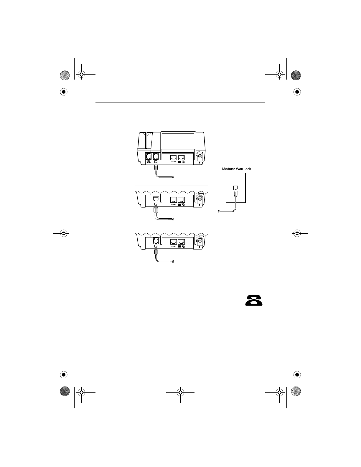
Step 4: Connect the Terminal to a Telephone Line
1. Direct connection — A telephone cord runs
from the Telco, ISDN, Dial/Leased-Line Port
on the terminal directly to a telephone wall
jack (Figure 4). With a direct connection, the
line is dedicated to the terminal.
11
Page 12
O3350 IG 19496 Book.book Page 12 Wednesday, April 5, 2000 10:30 PM
Omni 3350 Installation Guide
Omni 3350 Terminal
High-Speed Modem Terminal
ISDN Modem Terminal
12
Dial/Leased-Line Modem Terminal (Canada only)
Figure 4 Direct Connections
2. Pass-through connection (high-speed
modem only) — A telephone cord (VeriFone
part number 00124-17) runs from the Telset
port on the terminal to the RJ11-type jack on a
standard telephone (Figure 5). With a passthrough connection, the line is busy during transactions
and terminal downloads.
Page 13

O3350 IG 19496 Book.book Page 13 Wednesday, April 5, 2000 10:30 PM
Omni 3350 Installation Guide
Omni 3350 Terminal
(High-Speed Modem Only)
Figure 5 Pass-Through Connection
Step 5: Connect the Terminal Power Pack
Caution: Before you connect the terminal power
pack, check that the on/off switch is off (shown at
right).
1. Insert the round barrel connector (Figure 6)
into the power port (identified by the icon at
right).
Note: Th e round barrel co nnector on the po wer pack cable has
a plastic lock tab that secures the power cable to the terminal.
13
Page 14

O3350 IG 19496 Book.book Page 14 Wednesday, April 5, 2000 10:30 PM
Omni 3350 Installation Guide
Figure 6 Omni 3350 Power Pack Connection
To lock the connector into the power port,
align the plastic lock tab so it points up. Insert
the connector, then twist it as indicated by the
“arrow” icon above the port (“arrow” and
“lock” icons shown at right).
To unlock the connector, twist it to the right,
toward the “unlocked” icon (shown at right).
2. Plug in the power pack.
14
Warning: Do not plug the power pack into an outdoor outlet or
operate the terminal outdoors. Also, disconnecting power
during a transaction may cause transaction d ata files that are not
yet stored in terminal memory to be lost.
Note: To protect against possible damage caused by lightning
strikes and electrical surges, you may want to install a power
surge protector.
Page 15

O3350 IG 19496 Book.book Page 15 Wednesday, April 5, 2000 10:30 PM
Omni 3350 Installation Guide
When the terminal has power, the display screen lights and the
green LED indicator flashes on and off (if the printer has no
paper), or solid green if paper is loaded.
Step 6: Install a Paper Roll in the Printer
The internal printer uses single-ply, thermal-sensitive paper 58
millimeters (2.25 inches) wide and about 25 meters (82 feet)
long.
Warning: Poor-quality paper may jam the printer. For highquality VeriFone paper, refer to the “Accessories and
Documentation” section.
Caution: Store thermal paper in a dry, dark area. Handle
thermal paper carefully: impact, friction, temperature,
humidity, and oil affect the color and storage characteristics of
the paper. Never load a roll of paper with folds, wrinkles, tears,
or holes at the edges or in the printing area. For best results, cut
a straight edge on the paper with sciss ors bef ore feeding it into
the printer.
Install a Paper Roll
1. Turn on the terminal. (The green LED indicator will blink
on and off, indicating the printer needs p a per.)
2. Remove the paper roll cover by lifting it up (Figure 7).
Two ridges on the cover’s sides show where to grasp it.
15
Page 16

O3350 IG 19496 Book.book Page 16 Wednesday, April 5, 2000 10:30 PM
Omni 3350 Installation Guide
Paper Feed Button
Power-On/Paper-Detect
LED Indicator
Paper Release
Lever
16
Paper Roll Cradle
Figure 7 Thermal Printer Features
Paper Roll Cover
3. Remove the protective strip from the paper and cut a
straight edge across its leading end.
4. Hold the roll so the paper feeds from the bottom of the roll
and insert the cut end into the paper feed slot (Figure 8).
Printer Paper
Figure 8 Loading Paper
Page 17

O3350 IG 19496 Book.book Page 17 Wednesday, April 5, 2000 10:30 PM
Omni 3350 Installation Guide
A built-in sensor detects the paper and pulls it through and
out the unit’s top, just below the serrated metal tear strip.
5. If necessary, press the paper feed button until about
5 centimeters (2 inches) of paper emerge from the top.
6. Insert the orange plastic spindle into the paper roll, and
place into the cradle so the spindle’s ends rest securely in
the two slots.
7. Replace the cover by inserting the two front tabs first and
lightly pushing down until it snaps into place (Figure 9).
Ensure the paper’s edge is outside the cover.
Paper Roll Spindle
Figure 9 Paper Roll, Spindle, and Cover
Note: To adjust paper position, lift the small red release lever
on the cradle’s right side (Figure 7) until it snaps “up.” The
paper now freely moves in the paper path. When the paper is
correctly positioned, lower the lever until it snaps “down.”
For paper ordering information, refer to “Accessories and
Documentation‚” page 36.
17
Page 18

O3350 IG 19496 Book.book Page 18 Wednesday, April 5, 2000 10:30 PM
Omni 3350 Installation Guide
Perform a Power-On Printer Test
To ensure the printer is operating correctly:
1. Turn off power to the terminal.
2. Hold down the paper feed button and turn on the terminal.
The printer test starts, then stops after a few seconds.
When the test begins printing, release the paper feed
button.
The test printout, with printer information and repeating
character strings, is about 38 centimeters (15 inches) long.
3. Press the paper feed button to advance the paper roll a few
centimeters (inches), then tear off the test printout.
Congratulations! Your Omni 3350 terminal should now be
completely installed and ready to use.
Step 7: Instal l/Replace MSAM Cards
18
When you first receive your Omni 3350 terminal, you may
need to install a merchant smart card, or one or more
micromodule-size SAM (MSAM) cards. Or you may need to
replace old cards with new ones. The directions below describe
both procedures.
Caution: Observe standard precautions for handling
electrostatically sensitive devices. Electrostatic discharges can
damage this equipment.
1. Turn off power to the terminal.
2. T o install a merchant smart card, gr ip the SAM drawer and
pinch the locking lever (Figure 10). If the drawer already
Page 19

O3350 IG 19496 Book.book Page 19 Wednesday, April 5, 2000 10:30 PM
Omni 3350 Installation Guide
contains a merchant smart card, the lever grips the card for
removal from the terminal.
SAM Drawer
Merchant
Smart Card
Figure 10 SAM Drawer with Merchant Smart Card
Terminal
3. Slide the SAM drawer from the terminal (Figure 10).
4. Remove any previously-installed merchant smart card by
pulling the card from the SAM drawer.
To install or replace an MSAM card, go to Step 5.
Otherwise, go to Step 11.
5. Turn the terminal over (Figure 11) on a soft, clean surface
(to protect the lens from scratches). The four MSAM
cardholders are now accessible. Each cardholder consists
of a hinged tilt-up cover attached to a connector base.
19
Page 20

O3350 IG 19496 Book.book Page 20 Wednesday, April 5, 2000 10:30 PM
Omni 3350 Installation Guide
4 Micromodule-Size
SAM Cardholders
Figure 11 Micromodule-Size SAM (MSAM) Cardholders
6. To unlock a cardholder, slide its locking plate to the
unlocked position, shown by the OPEN arrow (Figure 12).
OPEN
20
LOCK
Figure 12 MSAM Cardholder Close-Up
7. Open the cardholder by pivoting the cover from its
connector base (Figure 13).
Page 21

O3350 IG 19496 Book.book Page 21 Wednesday, April 5, 2000 10:30 PM
Omni 3350 Installation Guide
Figure 13 Using an MSAM Cardholder
8. Remove any previously-installed MSAM card by sliding
the card from the cover.
9. Install an MSAM card by aligning the card and carefully
sliding it within the guides on the cover until fully
inserted.
Note: Th e car dho lder conn ector base has a set of contacts and
a notch post on one corner to ensure the MSAM card is
positioned correctly when the cover is closed. The MSAM card
has a notch on one corner to ensure it fits into the connector
base in only one way. Before inserting the MSAM card,
position it as shown in Figure 13, with the card’s gold contacts
facing the terminal’s base.
10. Pivot the cover into its connector base (Figure 13).
11. Lock each MSAM cardholder by sliding its locking plate,
as shown by the LOCK arrow, until the plate stops
(Figure 12).
21
Page 22

O3350 IG 19496 Book.book Page 22 Wednesday, April 5, 2000 10:30 PM
Omni 3350 Installation Guide
Caution: To avoid dam age to the MSAM cardho ld ers, ens ure
each cardholder is locked before sliding the SAM drawer back
into the terminal.
12. Insert a standard-size merchant smart card into the SAM
drawer as shown in Figure 10.
13. Slide the drawer back into the Omni 3350 terminal.
14. Lift up on the lever to lock the drawer into place.
Step 8: Use the Primary Smart Card Reader
1. To conduct a transaction, position a smart card and insert
it into the smart card reader slot in a smooth, continuous
motion until it seats firmly with a “click” (Figure 14).
Caution: Leave the smart card in the card reader until the
transaction is completed. Premature removal will invalidate the
transaction.
22
Figure 14 Using the Primary Smart Card Reader
2. When the display indicates the transaction is completed,
remove the card.
Page 23

O3350 IG 19496 Book.book Page 23 Wednesday, April 5, 2000 10:30 PM
Omni 3350 Installation Guide
Step 9: Use the Magnetic Card Reader
T o conduct a transaction, pos ition a magnetic card and s wipe it
through the magnetic card reader, as shown in Figure 15.
Figure 15 Using the Magnetic Card Reader
Connect Optional Device(s)
The Omni 3350 supports the complete line of VeriFone
peripheral devices designed for use with Point-Of-Sale
terminals. Use the two ports on the back panel to connect up to
two optional devices.
The following chart lists the most common optional devices
supported by this terminal. Other optional devices may be
supported. For more inform ation, please co ntact your VeriFone
distributor.
Optional Device
Barcode Reader PIN Pad
CR 600 RS232
Console PIN Pad
Connection Port
23
Page 24

O3350 IG 19496 Book.book Page 24 Wednesday, April 5, 2000 10:30 PM
Omni 3350 Installation Guide
Optional Device
External LAN RS232
PIN Pad PIN Pad
RS232 Electronic Cash Register RS232
Connection Port
Caution: Before connecting any peripheral device, turn off
power to the terminal (the LED is off). Turn on power only after
you are finished connecting the peripheral device(s). For
complete information about peripheral installation and use,
refer to the user documentation supplied with those devices.
Note: RS232-type devices do not work with the “PIN Pad”
port; PIN Pad-type devices do not work with the “RS232” po rt.
If an optional peripheral device does not function correctly,
check the port connection.
Connect PIN Pad, Smart Card Reader, or Bar Code
Wand
Refer to Figure 16:
1. If necessary, insert the small modular plug on one end of
the PIN pad cable into the PIN pad’s modular jack.
For a bar code wand, insert the RJ45-type plug on the end
of the cable into the “PIN Pad” serial port on the back
panel.
2. If installing a PINpad 101, PINpad 201, or PINpad 1000,
position and insert the grommet to secure the cable
connection, as shown in Figure 16.
If a cable is not already connected to the smart card reader
or PINpad 501, insert the small modular plug on one end
of the interface cable into the optional device’s modular
jack.
24
Page 25

O3350 IG 19496 Book.book Page 25 Wednesday, April 5, 2000 10:30 PM
Omni 3350 Installation Guide
3. Insert the larger RJ45-type connector on the other end of
the PIN pad cable into the “PIN Pad” serial port on the
terminal’s back panel.
PINpad 101/102/1000
Grommet
PINpad
Serial Port
Omni 3350 Terminal
Omni 3350
PIN Pad Port
PINpad 201/301/2000
SC 4xx / SC 5xx /
PINPAD 501
Figure 16 Optional “PIN Pad” port devices
Connect a CR 600 Check Reader
Caution: Check readers require a separate power source.
Before connecting a check reader or similar device, turn off
power to the terminal (the LED is off).
PINpad
Serial Port
Bar Code Wand
PINpad
Serial Port
25
Page 26

O3350 IG 19496 Book.book Page 26 Wednesday, April 5, 2000 10:30 PM
Omni 3350 Installation Guide
1. If the cable is not already connected to the check reader,
insert the small modular plug on one end of the cable into
the check reader’s modular jack (Figure 17).
2. Insert the larger RJ45-type connector on the other end of
the cable into the “RS232” serial port on the terminal’s
back panel.
Omni 3350 Terminal
Omni 3350
RS232 Port
CR 600
CR 600
Serial Port
Figure 17 CR 600 Check Reader Connection
3. Turn on power to the terminal, then connect the check
reader to a power source.
Cable Routing
VeriFone recommends the cable routing shown in Figure 18.
Note that the cable guides have two larger openings for the us e
with optional device cables, and two smaller openings for use
with telco and telset cables.
26
Page 27

O3350 IG 19496 Book.book Page 27 Wednesday, April 5, 2000 10:30 PM
Omni 3350 Installation Guide
Figure 18 Recommended Cable Routing
Clean the Terminal and Printer
Terminal
For dirt, use a clean cloth dampened with water and mild soap.
For stubborn stains, use alcohol or an alcohol-based cleaner.
Caution: Never use thinner, trichloroethylene, or ketonebased solvents — they may deteriorate plastic or rubber parts.
Do not spray cleaners or other solutions directly onto the
keypad or display. For best results, use a VeriFone Cleaning Kit
(refer to “Accessories and Documentation”).
Smart Card Reader
Caution: Do not attempt to clean the smart card reader . Doing
so may invalidate your warranty. For smart card reader service,
contact your VeriFone distributor or service provider.
27
Page 28

O3350 IG 19496 Book.book Page 28 Wednesday, April 5, 2000 10:30 PM
Omni 3350 Installation Guide
Printer
Every few months, check and thoroughly clean the printer:
1. Be sure the terminal is connected to a power source.
2. Remove the pa per roll cover and check it for signs of
damage, wear, or warping.
3. Remove the paper and spindle. Carefully cut from the roll
any paper still remaining in the feed mechanism.
4. Press the paper feed button to eject the remaining paper.
Caution: Do not attempt to pull paper from the printer.
Damage to the paper feed mechanism could result.
5. Remove any dirt, dust, or scraps of paper adhering to or
lodged in the printer parts.
6. Install a paper roll, as described in “Install a Paper Roll‚”
page 15.
Printer Troubleshooting
Printer Does Not Work
1. Check all terminal power connections. The integrated
printer receives its power directly from the Omni 3350
terminal. The green power-on indicator light should be on.
2. If the green power-on indicator is blinking on and off, the
printer is out of paper. Remove the paper roll cover and
install a new roll of printer paper , as described in “Install a
Paper Roll‚” page 15.
3. If the problem persists, contact your VeriFone distributor
or service provider.
28
Page 29

O3350 IG 19496 Book.book Page 29 Wednesday, April 5, 2000 10:30 PM
Omni 3350 Installation Guide
Printer Paper is Jammed in the Feed Mechanism
Warning: Poor-quality paper may jam the printer. For high-
quality VeriFone paper, refer to the “Accessories and
Documentation” section.
1. Remove the paper roll cover. Then, lift up the small red
lever located on the paper roll cradle’s right side until it
snaps “up.” (Figure 7). The paper can now move freely
through the paper feed mechanism.
2. Carefully cut the damaged paper from the paper roll and
clear the remaining paper from the feed mechanism.
3. Lower the paper release lever until it snaps “down.”
4. Re-install the roll of printer paper. If the problem persists,
it may be due to poor paper quality. Install a new roll of
higher-quality paper.
VeriFone Service and Support
For Omni 3350 terminal problems, contact your local
VeriFone representative or service provider.
For Omni 3350 product service and repair information:
• (USA) VeriFone Service and Support Group, 1-800-8349133, Monday - Friday, 8 A.M. - 7 P.M., EST
• (International) Contact your VeriFone representative
29
Page 30

O3350 IG 19496 Book.book Page 30 Wednesday, April 5, 2000 10:30 PM
Omni 3350 Installation Guide
Returning a Terminal for Service
Note: The Omni 3350 terminal comes equipped with tamper-
evident labels (one on the case seam, another on a screw hole
on the case bottom). Do not, under any circumstance, attempt
to disassemble the terminal. Perform only those adjustments or
repairs specified in this installation guide. For all other
services, contact your local VeriFone distributor or service
provider. Service conducted by parties other than authorized
VeriFone representatives may invalidate the product warranty.
1. Gather the following information from the printed labels
on the bottom of each Omni 3350 terminal (Figure 19):
• Serial number (S/N xxx-xxx-xxx)
• Product ID, including the model and part number.
For example, “Omni 3350” and “P093-xxx-xx”
VeriFone Product ID
VeriFone Serial N umber
30
Figure 19 Information Labels on Bottom of Terminal
2. Contact your VeriFone distributor or service provider and
give them this information.
3. Describe the problem(s) and provide the shipping address
where the repaired or replacement unit will be returned.
4. Keep all records of the following items:
Page 31

O3350 IG 19496 Book.book Page 31 Wednesday, April 5, 2000 10:30 PM
Omni 3350 Installation Guide
• VeriFone serial number assigned to the Omni 3350
terminal you are returning for service or repair.
• Shipping documentation, such as airbill numbers,
which you can use to trace the shipment.
Specifications
Power Requirements
Omni 3350 terminal: 25,5 V DC (25.5 V DC); 1,2 A (1.2 A)
DC power pack:
• Input: 100 - 250 V ~ (100 - 250 V AC); 50 - 60 Hz;
1,2 A (1.2 A)
• Output: 25,5 V DC (25.5 V DC); 1,57 A (1.57 A)
Barrel Connector Polarity:
Environmental
• Operating temperature: 0° to 55° C (32° to 131° F)
• Storage temperature: – 40° to + 70° C (– 40° to 158° F)
• Relative humidity: 15% to 90%; no condensation
Dimensions
• Height: 78.5 mm (3.09 inches)
• Width: 150 mm (5.9 inches)
• Length: 294.7 mm (11.6 inches)
Weight
• Terminal unit weight: 1.28 kg (2.82 lb)
• Shipping weight: 3.26 kg (7.19 lb)
–
+
31
Page 32

O3350 IG 19496 Book.book Page 32 Wednesday, April 5, 2000 10:30 PM
Omni 3350 Installation Guide
The shipping weight includes: shipping carton, terminal,
power pack and cable, telephone line cable, paper roll and
spindle, one Omni 3350 Installation Guide, and one
Omni 3350 Quick Installation Guide.
32
Page 33

O3350 IG 19496 Book.book Page 33 Wednesday, April 5, 2000 10:30 PM
Omni 3350 Installation Guide
DECLARATION OF CONFORMITY
according to ISO/IEC Guide 22 and EN 45014
Manufacturer’s Name: Hewlett-Packard Company VASD
Manufacturer’s Address: VeriFone
declares that the product:
Product Name: Omni 3350
Model Number: P093-300-XX
Product Options: All
conforms to the following Product Specifications:
Safety: IEC 60950:1991+A1+A2+A3+A4
EMC
Supplementary Information:
The product herewith complies with the requirements of the Low Voltage Directive 73/23/EEC
and the EMC Directive 89/336/EEC and carries the CE marking accordingly.
This equipment is designed to work in and complies with Council Decision 98/482/EC
(CTR21) requirements and compliant networks within Europe. If it is necessary to operate this
equipment on a different telephone network, contact your local sales representative, or
contact VeriFone Division of Hewlett-Packard Company at the address shown in the user
guide.
1) The product was tested with VeriFone Point of Sale (POS) systems.
EN 60950:1992+A1+A2+A3+A4+A11
CISPR 22:1993 +A1+A2 / EN 55022:1994 +A1+A2 - Class B
IEC 801-2:1984 / EN 50082-1:1992 - 4 kV CD, 8 kV AD
IEC 801-3:1984 / EN 50082-1:1992 - 3 V/m, 27-500 MHz
IEC 801-4:1988 / EN 50082-1:1992 - 0.5 kV Signal Lines,
3755 Atherton Rd.
Rocklin, CA 95765
USA
1 kV Power Lines
1)
Rocklin, CA USA
MM DD, 1999
European contact for regulatory topics only: VeriFone (UK) Ltd
Larry Forman
Quality Manager
Salamander Quay West
Park Lane, Harefield
Uxbridge, Middlesex
UB9 6NZ United Kingdom
Tel: (44) 1895 824031
33
Page 34

O3350 IG 19496 Book.book Page 34 Wednesday, April 5, 2000 10:30 PM
Omni 3350 Installation Guide
Product Certifications
FCC Compliance
Manufacturer: VeriFone, a division of Hewlett-Packard Company
Omni 3350
Model:
FCC Part 15
This equipment has been tested and found to comply with th e limi ts fo r a Class B digi ta l
device, pursuant to Part 15 of the FCC Rules. These limits are designed to provide
reasonable protection against harmful interference in a residential installation.
This equipment generates, uses, and can radia te radi o frequency energy and, if not
installed and used in accordance with the instruction s , may cause harmful interference to
radio communications. How ever, there is no guarantee that interference will not occur in
a particular installation.
If this equipment does cause harmf ul int erference to radi o or tele v isi on reception, whi ch
can be determined by turning the equipment off and on, the user is enc ouraged to try to
correct the interference by one or more of the following measures:
• Reorient or relocate the receiving antenna.
• Increase the separation between the equipment and receiver.
• Connect the equ ipment into an outlet on a circuit different fr om th at to which the
receiver is connected.
• Consult the dealer or an experienced radio/TV technician for help.
FCC Part 68
This equipment complies with Part 68 of the FCC rules. On the modem board inside this
equipment is a label that contains, among other information, the FCC registration number
and ringer equivalence number (REN) for t his e qui pme nt . If requested, this informatio n
may be provided to the telephone company.
The REN is used to determine the quantity of devices that may be con ne cted to the
telephone line. Excessive RENs on the telephone line may result in the devices not ringing
in response to an incoming call. In most, but not all, areas, the sum of the RENs should not
exceed five (5.0). To be certain of the number of devices that may be connected to the line,
as determined by the total RENs, co ntact the telephone com pany to determine the
maximum RENs for the ca lling area.
This equipment cannot be used on telephone-company-provided coin serv ic e. Connection
to Party Line Service is subject to state tariffs.
This equipment uses the following USOC jacks: (RJ11C).
An FCC compliant telephone cord and modular plug is provided with this equipment. This
equipment is designe d to be connected to the tel ep hone network or premises wiring using
a compatible modular jack that is Part 68 compliant.
If this equipment causes harm to the telephone network, the telephone company will notify
you in advance that temporary discontinuance of serv i ce ma y be required. If advance
notice isn’t practical, the telephone company will notify the customer as soon as possible.
34
Page 35

O3350 IG 19496 Book.book Page 35 Wednesday, April 5, 2000 10:30 PM
Omni 3350 Installation Guide
Also, you will be advised of your right to fi le a complaint with the FCC if you believ e it is
necessary.
The telephone company may make changes in its facilities, equipment, operations, or
procedures that could affect the operation of the equipment. If this happens, the telephone
company will provide advance notice in order for you to make the necessary modifications
in order to maintain uninterrupted service.
If trouble is experienced with this equipment, pl ease contact VeriFone, or your local
VeriFone Distributor or service center in U.S.A. for repair and/or warranty information.
If the trouble is causing harm to the telephone network, the telephone company m a y
request you remove the equipment from the netw ork until the problem is resolved.
No repairs can be done by a customer on this equipment.
It is recomme nded t hat th e cust omer i nsta ll an AC surge arr esto r in th e AC outlet to w hich
this device is connected. This is to avoid damaging the equipment caused by local
lightning strikes and other electrica l surges.
Industry Canada NOTICE:
The Industry Canada label identifies certified equipment. This certification means that the
equipment meets certain telecommunications network protective, operational, and safety
requirements as prescribed in the appropriate Terminal Equipment Technical
Requirements document(s). The Department does not guarantee the equipment will
operate to the user’s satisfaction. Before installing this equipment, users should ensure
that it is permissible to be connected to the facilities of the local telecommunications
company. The equipment must also be installed using an acceptable m et hod of
connection. The customer should be aware that compliance with the above conditions may
not prevent degradation of service in some situations. Repairs to c ertif ied equipment
should be coordinated by a representative designated by the supplier. Any repairs or
alterations made by the us er to this equipment, or equipment malfunctions, may give the
telecommunicat ions company cause to request the user to di sconnect the equipment.
Users should ensure for their own protection that the electrical ground connections of the
power utility, telephone lines and internal metallic w ater pip e syst em, if present, are
connected together. This precaution may be particularly important in rural areas.
Caution: Users should not attempt to make such connections themselves, but should
contact the appropriate electric inspection authority, or electrician, as appropriate.
35
Page 36

O3350 IG 19496 Book.book Page 36 Wednesday, April 5, 2000 10:30 PM
Omni 3350 Installation Guide
Accessories and Documentation
How to Order
• VeriFone Online Store at www.store.verifone.com
• (USA) VeriFone Customer Development Center, 1-800233-0522, Monday - Friday, 7 A.M. - 5 P.M., MST
• (International) Contact your VeriFone representative
Download Cables
05651-xx MOD10-MOD10 (terminal-to-terminal)
26263-xx 02xxx MOD10-PC DB25F (terminal-to-PC)
26264-xx 02xxx MOD10-PC DB9F (terminal-to-PC)
Cables for Optional Peripherals
07041-xx MOD10-MDIN9 (CR 600 check reader)
07042-xx MOD10-4P4C (all VeriFone PIN pads)
07458-xx MOD10-4 PIN SOCKET (terminal-to-
CM 450)
36
Terminal Mounting Platform
07129-xx Plastic base for mounting onto a flat surface
07456-01 Swivel stand
Telephone Line Cord
00124-17 2.1-meter (7-foot) telephone line cord, black
color, with modular RJ11-type connectors
Power Pack
Contact your local VeriFone distributor to determine which
power pack fits your needs.
05790-03 DC power pack
Page 37

O3350 IG 19496 Book.book Page 37 Wednesday, April 5, 2000 10:30 PM
Omni 3350 Installation Guide
Thermal Printer Paper
CRM0039 High-grade thermal printer paper, 58-mm
(2.25-inch) width, 25-meter (82-foot) length;
single roll
CRM0039-01 CRM0039 in 30-roll bulk package
CRM0040 High-grade thermal printer paper, 58-mm
(2.25-inch) width, 33-meter (108.26-foot)
length; single roll
Paper Roll Spindle
02117-03 Plastic spindle for 58-mm (2.25-inch) rolls of
thermal printer paper; orange color
VeriFone Cleaning Kit
02746-01 Cleaning Kit
Documentation
22131, Rev. A Omni 3350 Installation Guide
19784, Rev. A Omni 3350 Quick Installation Guide
19732, Rev. B Omni 33XX Series Reference Manual
19733, Rev. B Omni 33XX Series SDK Programmer’s
Manual
37
Page 38

O3350 IG 19496 Book.book Page 38 Wednesday, April 5, 2000 10:30 PM
Omni 3350 Installation Guide
38
Page 39

O3350 IG 19496 Book.book Page 39 Wednesday, April 5, 2000 10:30 PM
Omni 3350 Installation Guide
39
Page 40

O3350 IG 19496 Book.book Page 40 Wednesday, April 5, 2000 10:30 PM
2099 Gateway Place
Ste 600
San Jose, CA 95110, USA
Telephone: (+1) 408-232-7800
Fax: (+1) 408-232-7811
World Wide Web: www.verifone.com
Omni 3350
Installation Guide
VeriFone Part Number 22131, Revision B
© 2000 VeriFone
All rights reserved.
Printed on recycled paper.
 Loading...