

Page 1

V4.73
VEREX Director
User's Guide
Page 2

Page 3

Contents
Using this Guide ..................................................................................................................................... v
Welcome .....................................................................................................................................................1
Entering an Area & Disarming the Sy
Welcome to VEREX
Start-up and Logging In
Ex
T
Other Desktop Choices
Runnin
Checking Status and Controlling Items
21-0381E v4.7.3 (2008.08) © 2008 CSG Security Inc. / Sécurité CSG Inc. i
g Reports, and Monitoring System Activity .............................................................................. 13
ime-and-Attendance Reporting........................................................................................................... 14
T
Required-Attendance T
Roll-Call Reports (v4.61) ......................................................................................................................20
Reporting on System & Personnel Activity ...........................................................................................21
Reporting on Previous Guard-T
Reporting on User Access Authorities (by
Reporting on Users, S
Reporting on Operator Audits or Panel Com
Reporti
Working w
Monitoring Sy
Alarm and Activit
'Activating' and Using the Monitoring Windo
Limiting the Windo
Ackno
When Messages Cannot be
W
Visually Verifying Users (Photo-Verification) ........................................................................................ 44
Guard-T
Guard T
Maps and Video (Visual Monit
Status and Control Using Vis
Camera Status/Control and Adjustments
Initial Set Up of
Checking Status & Controlling Items
Introduction to Status & Control
Using the Status Toolbar ........................................................................................................... 78
Miscellaneous Status Tasks ...................................................................................................... 80
Checking the S
Checki
Checking the Status of Modules ................................................................................................92
Checking Status or Controlling a Suite Securit
stem .............................................................................................2
Director .................................................................................................................. 4
............................................................................................................... 4
iting, Logging Off, or Changing Operators ...............................................................................6
he Desktop ................................................................................................................................ 8
.............................................................................................................. 10
ime-Periods........................................................................................... 18
ours..................................................................................................... 24
Area, Door, or Floor) .......................................................... 26
ystem/Device Settings, etc. ............................................................................... 28
munications Logs ............................................................ 30
ng on Panel Diagnostics (≥V4.4)............................................................................................... 32
ith the Report Viewer ...........................................................................................................34
stem Activity.................................................................................................................... 35
y Monitoring .................................................................................................... 35
w............................................................................ 36
w to Show Only Specific Messages (Sorting and Filtering) .......................... 38
wledging Alarms (Comment / Resolve)............................................................................ 40
Transmitted to the VEREX Director Software ...............................41
orking with Video Events (≥V4.5)............................................................................................ 42
ours: Monitoring...................................................................................................................... 47
ours: Initial Set Up ....................................................................................................... 50
................................................................................................. 53
oring & Status/Control) .......................................................................... 54
ual Director................................................................................... 54
................................................................................... 62
Controlling a Pan/T
Adjusting Cam
: Views, Maps, Cameras................................................................................... 68
Panel Date and T
Resetting Users' Antipassback Status
Clearing
Checking S
ng Power Levels (≥V4.4)................................................................................................. 90
a "Bad Card/PIN Global Lockout".................................................................... 84
ystem Status (Remote Diagnostics) ............................................................ 86
tatus of Panels (Equipment) .............................................................................. 88
ilt/Zoom Camera ............................................................................. 63
era Quality for your Connection/Bandwidth............................................ 66
.................................................................................................... 76
................................................................................................. 76
ime..................................................................................................... 80
........................................................................... 82
y System............................................................ 94
Page 4

Checking Status or Controlling Items by Area ........................................................................... 96
Area Users (Ac
Checking User In/Out Status
Checking Status or Controlling Individual Doors
Checking Status or Controlling Elevators
Checking Status or Controlling Floors
Checking Status or B
Checking Status or Controlling Outputs (Electronically
Panel Communications and Updates
Panel Communications
Activating Communications and T
Vie
wing the Status of Previous Communications Sessions ..................................................... 120
Correcting Communication/Update Errors
Checki
ng Account Status (≥V4.4)....................................................................................................... 124
l Firmware Files, and Updating Panel Firmware (≥V4.4) ............................................................ 125
Pane
Activating Panel Firm
Updating Panel Firmw
dministration and Maintenance ......................................................................................................... 129
A
Operators (People Who Can Use
Setting or Changing an Operator's Pass
Operator Settings (v4.6)
Operator Permissions
Scheduled Event Filtering for
Schedules for
Holiday
Authorit
Authoriti
Custom Information Categor
Users (Entrant
T
Cards that Hav
Fall-Back Users (Can Enter During Comms Failure)
ystem Maintenance Tasks ............................................................................................................... 170
S
Pass
Large S
Client/Server S
Checking / Repairing the VEREX
Backing up or
Ex
Removing old
Operating Sy
User-Access and Area Automation.............................................................................. 140
s and Time-Change Dates...................................................................................................... 144
y Groups to Manage Large Numbers of Authorities (v4.6) .................................................... 146
es for Users/Entrants (≥V4.4) ................................................................................................ 148
s / Panel Users)........................................................................................................... 156
he Photo-Badging Option ...................................................................................................... 162
e Been Lost...................................................................................................... 166
word and Personal ID Number (PIN) Issues.................................................................... 170
ystems--Checking for Software vs. Panel Differences / Conflicts................................ 172
ystems: Checking to See Who Else is Logged onto the Database ................ 173
Restoring the Database .................................................................................... 176
Making
Making
Setting Backups to Occur Automatically
Reverting to (Restoring) a Bac
porting or Importing Activity or Audit Logs (Archive)............................................................ 182
Activity or Audit Logs (Purge)............................................................................ 184
stem Maintenance............................................................................................... 185
tivity, User Count, and APB-Reset)....................................................... 99
................................................................................................... 102
...................................................................... 104
................................................................................ 106
..................................................................................... 108
ypassing Input Points (Sensors)............................................................. 110
switched Devices)............................. 112
................................................................................................. 114
............................................................................................................ 114
ransferring Panel Settings .................................................. 116
............................................................................... 122
ware Files............................................................................................... 125
are ........................................................................................................ 126
This Software)............................................................................... 130
word.......................................................................... 132
.......................................................................................................... 134
.............................................................................................................. 136
Operators.................................................................................. 138
ies for Users (Custom User Information) ............................................... 154
............................................................... 168
Director Database Tables ................................................... 174
a Database 'Backup' Using the Director Software .......................................... 177
a Database 'Backup' Using the Table Repair Utility........................................ 178
(Scheduled Backups) v4.5........................... 179
kup Copy of the VEREX Director Database ................ 180
ii VEREX Director V4.73 User's Guide 21-0381E v4.7.3
Page 5

System Configuration............................................................................................................................ 187
Working
Users and Holiday
with Accounts and Folders (Multi-Account Systems)............................................................ 188
Visual Quick-Start
After a Multi-Server Login
Advanced Sorting
.................................................................................................................... 188
........................................................................................................ 191
..................................................................................................................... 192
s Shared Across Multiple Accounts ....................................................................... 193
Introduction
.............................................................................................................................. 193
Phase 1: Account-Specific Data.............................................................................................. 194
Phase 2: Community Groups.................................................................................................. 196
Phase 3: Shared Users and
Phase 4: Assign Shared Items to Accounts
Account-Wide Panel Settings (Feature-Set,
Event Respons
es for Acknowledging Alarms ..................................................................................... 208
Holidays ..................................................................................... 200
............................................................................ 202
Service PIN, etc.) .......................................................... 204
Alarm / Event Instructions................................................................................................................... 210
Enabling Sounds (to be associated with event/alarm messages)....................................................... 212
Customizing Ho
Detail
ed Operator and User Audit Trail (≥V4.6) .................................................................................. 216
w Events are Displayed (Event Priority) .................................................................... 214
Setting up Video Events (≥V4.5)......................................................................................................... 217
ware-Based Text Paging (Serial Reporting) ≥v4.4 ....................................................................... 218
Soft
Panels, Panel
Panel Groups
S
stem Settings for each Panel (≥V4.4)............................................................................................. 224
Sy
General S
Intrusion Settin
Groups, and Connection Settings .............................................................................. 220
and Connection Settings ................................................................................... 220
ystem Panels and Displayed Item-Numbers.......................................................................... 222
ystem Settings for a Panel....................................................................................... 224
gs for a Panel (≥V4.4) ...................................................................................... 226
Monitoring, Numeric Paging, & Remote Mgt. Settings............................................................. 228
Sy
stem Card-Access Settings ................................................................................................. 232
Equipment Set
Areas and Related Settings.
Activit
Area Groups (≥V4.4) and Multi-panel Arm/Disarm (≥V4.5)
tings (Pseudo / Internal Inputs) ................................................................................... 234
............................................................................................................... 236
y Monitoring and Auto-Arming........................................................................................ 242
................................................................ 244
Setting up Multi-Panel Arm/Disarm (≥V4.5) ............................................................................. 245
pansion Modules ............................................................................................................. .............. 246
Ex
Suite-Securit
Doors, Reader
Elevators (Lifts
Floors (Pertaining to Access-Controlled Elevators / Lifts)
Input Points—
Programmable Outputs (Signalling & Device-Sw
Programmable Output Functions
y Keypads and Related Settings .................................................................................... 250
s, and Related Settings ...............................................................................................254
Defining a ‘Required Attendance’ Zone
About Video E
vents .................................................................................................................261
................................................................................... 257
) and Associated Readers........................................................................................... 262
................................................................... 268
Monitored Sensors ....................................................................................................... 270
Input Points—
Input Points—
Custom Circuit-T
Pre-Defined Sensor Types ................................................................................274
Custom Point Types .......................................................................................... 275
ypes for Input Points (≥V4.4)......................................................................... 278
itching).................................................................... 280
T
he Numeric Paging Feature ...................................................................................... 280
Event T
Commands (
Cadence (Getting the Output to Pulse On and Off) (≥V4.2):
Multi-Condition Equations:
ypes and Events:............................................................................................. 282
when you right-click an item):.................................................................. 283
....................................... 283
........................................................................................... 283
........................................................................................................ 285
21-0381E v4.7.3 (2008.08) © 2008 CSG Security Inc. / Sécurité CSG Inc. iii
Page 6

Installation and Technical Reference................................................................................................... 291
PC Issues and
Recommended Computer Specifications
Serial Port Installation and Set Up
Windo
Soft
Upgrading from an Earlier Version
DCOM Setup
Fire
Soft
ware Activation and Licensing...................................................................................................... 303
Soft
Activating Your Soft
Upgrading Your Soft
March Net
work USB HASP Key (Director ≥V4.51)........................................................................................ 306
Net
Remote Soft
Client/Server Issues and the
Client/Server A
Server Vali
Client Access (Allowable Client List)........................................................................................ 312
Setting Up Client Permissions
Ne
w Installation? Try the Wizard !..................................................................................................... 318
Panel Connection Overvie
IP Connectiv
Secure IP Communications (≥V4.72)
PC-to-Panel—Direct Connect
PC and Panels
Serial Port / Modem Setup (Communications Manager) .................................................................... 326
Communication Pools for S
Setting Up a Ne
Importing Settings from an E
Customizing the My
Sy
stem Capacities.............................................................................................................................. 340
ed Database Features ............................................................................................................ 345
Advanc
Overvie
SQL Server Support
User-Logins (Needed for: Databas
Linking to the
Automated User-Import (Used for: ERM Int
Manually
Sy
stem / Hardware Reference ........................................................................................................... 355
ypad Tone Reference (≥V4.5 with ≥V4.42 firmware)...................................................................... 358
Ke
On-Line Support & Product Information
Index
....................................................................................................................................................... 361
Software Installation................................................................................................... 292
................................................................................. 292
........................................................................................... 294
ws Settings Required..................................................................................................... 295
ware Installation for a Fresh/New System ......................................................................... 297
of Software........................................................................ 298
If You Need to
........................................................................................................................... 302
wall Settings (e.g., Windows XPsp2)................................................................................. 302
ware "Activation Key" ........................................................................................................ 303
works R4-R5 DVR Support ................................................................................................ 306
ware Download and Remote Access (≥V4.7) ................................................................. 308
ccess and Permissions............................................................................................... 311
dation Certificates (≥V4.72) .................................................................................... 311
ity......................................................................................................................... 321
—Modem Connections .................................................................................... 324
PC Modem Ins
ws Modem Setup .............................................................................................. 324
Windo
Panel Modem .............................................................................................................. 325
w System (Commissioning)....................................................................................... 332
Tools Bar............................................................................................................. 338
w of Features............................................................................................................... 345
Database (Used for: Custom Query/Reporting; ERM Integration)................... 348
Importing User-Data From a Text File ...................................................................... 354
Transfer the Database to a Different PC ............................................. 300
ware ......................................................................................................... 303
ware (Adding Optional Features)............................................................. 305
Director Server Manager (v4.7) ............................................................ 309
................................................................................................. 316
w ............................................................................................................... 319
....................................................................................... 321
ion ............................................................................................. 322
tallation or Connection......................................................................... 324
ystem Panels........................................................................................... 330
xisting VEREX Director System Panel....................................... 336
................................................................................................................ 345
e Query, and SQL Server Support) .................................. 346
egration).............................................................. 352
.............................................................................................. 360
iv VEREX Director V4.73 User's Guide 21-0381E v4.7.3
Page 7

Using this Guide
Each topic th at pertains to a specif ic VEREX
Director screen generally sho ws ho w t o do
things on th e left, and w hat t he av ailable
settings mean on the right. This may pertain
to a sing le pa ge, or sets of 'facing pages ' as
required for larger topics. A b old double-line
marks the en d of each 'Ho w-To' section, and
the 'selection -descriptions' for the present
screen follow thereafter.
Use the table of contents (at the front), or the
index (at the back) to find a desired topic. The
table of contents sho ws the topics as they
appear in ea ch chapter, while the index lists
topic keywords alphabetically.
Tip: The bottom of each right-hand page shows you
which chapter you are presently 'in'. (These match the
topic-buttons across the top of the on-line help.)
To find specific information within a topic, skim
through the s ubheadings ( on the left), o r the
selection-descriptions for th e specific scr een
(on the right) to find what you're looking for.
Tip: Additional notes, and links to other applicable
sections are provided throughout. You can typically
avoid reading the note text unless you run into
problems or otherwise feel that you need more
information.
On-Line Help Tip: The on-line help is structured in the
same basic format as this User's Guide, with topic
buttons that match the chapters and navigation footers
in this guide. As you refer to the User's Guide, you are
already becoming familiar with the on-line help (and
vice-versa).
Copyrights and Trademarks
™ VEREX Director, G-Prox, and Netvision are
trademarks of CSG Security Inc.
Inc.
™ Pentium is a trademark of Intel Corporation
® Microsoft, Windows, Windows 2000, and
Windows XP, are trademarks or registered
trademarks of the Microsoft Corporation.
© Copyright 2008
CSG Security Inc.
All rights reserved.
/ Sécurité CSG Inc.
/ Sécurité CSG
Disclaimer
All soft ware, firmw are, draw ings, diagrams,
specifications, catalogues, literature, manuals
and other supplied materials shall con stitute
the proprietary information of the
manufacturer. In the interests of ongoing
improvement in quality and design, we reserve
the right to change pro duct specific ations
without prior notification.
Attention: Physical a lteration of hardw are
components or removal of electrical de vices
may void warranties, and/or affect radiofrequency and electromagnetic emissions.
This document is not to be copied, decompiled, or re-distributed in any form without
prior written consent.
© Copyright 2008
CSG Security Inc.
/ Sécurité CSG Inc.
21-0381E v4.7.3 (2008.08) © 2008 CSG Security Inc. / Sécurité CSG Inc. v
Page 8

vi VEREX Director V4.73 User's Guide 21-0381E v4.7.3
Page 9

Welcome
21-0381E v4.7.3
Welcome Report Control Admin Sys Config Tech-Ref
1
Page 10
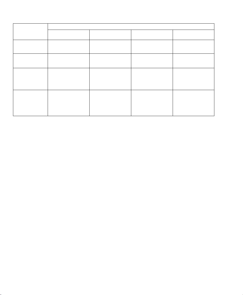
Entering an Area & Disarming the System
Re ader/Door Mode
Area
Setting
Disarmed (Off)
Armed & 'Auto
Disarm on Valid
Token'
Armed & 'PINOnly' or 'ID+PIN'
Armed &
Dual Custody
Locked &
Card Only
Present card,
open the door
Present card,
open the door
Present card, open the
door. Then log into
panel and disarm it.
Present card, open the
door. Then login with
two user PINs (or
ID+PIN), & disarm
area.
Locked &
Card+PIN
Present card, enter PIN
open the door
Present card, enter PIN
open the door
Present card, enter PIN
open door. Then log
into the panel & disarm
it.
Present card, enter PIN
open door. Then login
with two user PINs (or
ID+PIN), & disarm
area.
Locked &
Card or UID/PIN
Present card or enter
user no., enter PIN
open the door
Present card or enter
user no., enter PIN
open the door
Present card or enter
user no., enter PIN
open door. Then log
into the panel & disarm
it.
Present card or enter
user no., enter PIN
open door. Then login
with two user PINs (or
ID+PIN), & disarm
area.
Locked &
UID/PIN Only
Enter UID+PIN (or PIN
only), open the door
Enter UID+PIN (or PIN
only), open the door
Enter UID+PIN (or PIN
only), open the door.
Then log into panel and
disarm it.
Enter UID+PIN (or PIN
only), open the door.
Then login with two
user PINs (or ID+PIN),
& disarm area.
2 VEREX Director V4.73 User's Guide 21-0381E v4.7.3
Page 11

If the door is unlocked, access is not controlled (simply
open the door to enter the area). Conversely, if the
door is locked, and all cards are presently 'locked out
users will be unable to enter.
Card Number
(UID), and/or access cards, the system can be set for
entry and login using the card number instead (4-10
digits).
Visitors that must be Escorted
as "Visitor (Escort-Required)" must be escorted at each
controlled reader (valid escort or regular cardholder-depending on the system settings).
To enter at a controlled door and disarm the area, an
entry delay must be in effect. As well, only the users
with authority to both enter the door at this time AND
disarm the area will be granted entry.
The 'ID + PIN' or 'PIN Only' login requirement is
determined by the 'Feature-Set' selection for the
account.
Dual Custody (and Escort mode) is supported at
individual readers as well.
: As an alternative to the user ID number
: Persons with a card set
',
Using an Arming Station: Additional features
and entry options are provided through an
arming station. These unit s are essentially a
proximity rea der w ith keyp ad, plus addit ional
status indicators and features. For details on
using an arming station, please refer to th e xL
(panel/keypad) User's Guide.
Readers set to Enable or Disable Cards:
Some readers may be set to enable or disable
specific types of cards (su ch as visitor cards,
or all temporary cards, etc.)--with or without an
associated door being unlo cked at this time.
All other (valid) cards will be granted access as
usual.
Note: Cards can either be disabled permanently, or
allowed to be re-enabled later.
To Enter using a Do or-Opener Button: Use
your access card and/or PIN to unlock the door
(and activate the button). Then, simply press
and release t he door-opener button. Once
inside the area, 'log' in at a n LCD keypad, and
disarm the ar ea if required (i.e., if NOT set for
"Auto-Disarm on Valid Token").
If Y ou ar e Being For ced to E nter: With
Card+PIN mo de in effect, you can trigger a
'Duress' alarm by reversing the last 2-digit s of
your personal ID number (P IN). This can also
be done when 'logging' into an LCD keypad.
To Exit Using an RTE (REX) Button: Simply
press and b riefly hold t he request-to-ex it
button.
If you Hold the Door Open: If the door is
held open for 'too long', a 'Door Held Open'
message will be logged.
A person holding a door open, or indicating that they
are being forced to enter may also trigger an alarm
(depending on the monitoring settings for the specific
door).
Entering Dur ing the P re-Arming Cy cle:
With a sched uled arming, authorized persons
entering during the 15 minute pre-arming cycle
will be granted access--without interrupting the
arming cycle. They would then have to:
+ Extend the closing time ("work-late"), or
+ Manually disarm the area once the final pre-
arm countdown begins, or;
+ Leave before the arming occurs.
21-0381E v4.7.3
Welcome Report Control Admin Sys Config Tech-Ref
3
Page 12

Welcome to VEREX Director
Start-up and Logging In
Multiple Instances: Beginning with Director v4.70, you
can run multiple copies of the interface (…Director.exe).
This allows you to access different features and/or
different accounts at the same time.
Starting the VEREX Director Software
Select Start, Programs, VEREX Di rector V4,
and VEREX Director, and wait for the start-up
screen to appear.
Activation Key: The VEREX Director software uses a
small 'activation key' to manage software licensing and
optional features. This device must be plugged onto
the PC that contains the software database (≥V4: USB
connector; ≤V3.3.2: Parallel/printer port; V3.3.3:
Either).
Note: Director software ≥V4 will not start up if the
USB key is missing.
Client/Server Systems:
VEREX Director software is NOT already running
before attempting to start it. Troubleshooting Tip
desktop is acting strangely, you may have two copies of
the software running (and you've run out of memory).
Logging In (Single-PC)
To gain access to your a ssigned items and
features, you must first perform a 'Login':
Select Login from the toolb ar, and then enter
your name and pass word, pressing Tab in
between. Then, press Enter, or click Login.
Take care to ensure that the
: If the
shut down the software (incl. the communications or
server module), then start the software and login again.
On-Line Help Language
For versions of VEREX Director that in clude
multi-language help file s, t he on-line help will
normally come up in the la nguage associated
with your op erator settings. You can als o
select a different language-version if desired
(for this work-session).
Selecting a Different Help Language: Open the Help
menu, select L
available choices.
anguage, and then select from the
The Auto-Lockout Feature
If you do not use your keyb oard for a sp ecific
period of time , the soft ware will automatically
go into 'lockout' mode to protect against an
unauthorized person view ing or changing
items. (For details, refer to the [Lockout]
description).
To set the period of time before the keyboard lockout
will occur (when you are logged in), refer to the section
on "Operators".
Logging In (Client/Server)
Select Login from the toolb ar, and then enter
your name and pass word, pressing Tab in
between. (Ensure the "Server Location" is set
as well, if present.) Then, press Enter, or click
Login.
If a "Cannot Connect to Server" screen
appears, check that you have not mistyped the
"Server Location".
Note: The Director-server PC and software must be
running (this is the PC that includes "...DirectorServer.exe", and typically contains the database as
well. For additional things to check, refer to "Director
Server Manager and Client/Server Issues" (near the
back of this guide).
If you just upgraded for client/server
missing on login screen): You may need to login once,
(server location
4 VEREX Director V4.73 User's Guide 21-0381E v4.7.3
Page 13
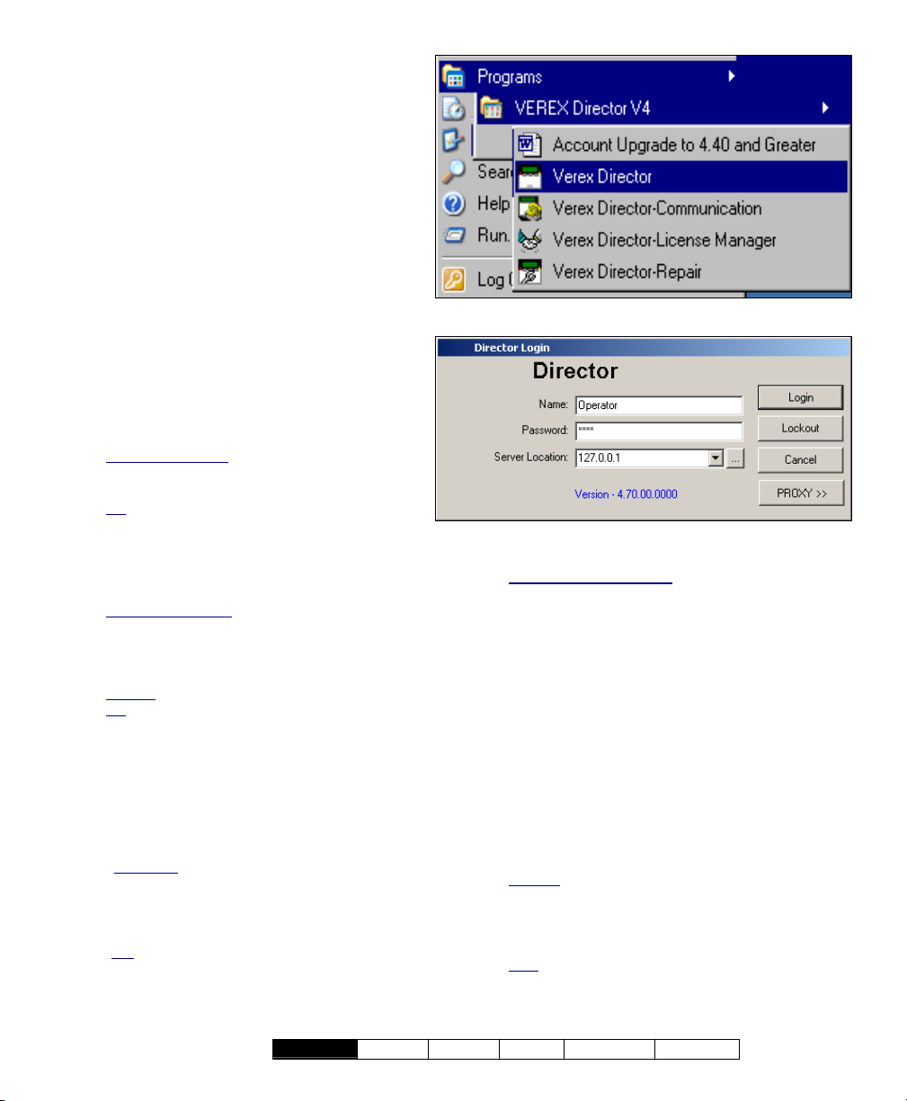
- Name: A valid operator's name.
- Password: The operator's assigned
password.
Default Operator Name & Password:
Operator, 1234
The default login name and password take effect
only until changed by a system administrator.
To protect against unauthorized access to the
software, the default password should be
changed right away.
If your login name and password are no longer
supported after upgrading from an earlier
software revision, refer to "Upgrading from an
Earlier Version of Software", paying special
attention to converting your previous database.
- Server Location: In a multi-PC (clientserver) installation, this allows you to
identify the VEREX Director server. Select
(or type in) the server "PC name" (or its
network "IP address").
Director-Server PC: This is the PC that includes
"...Director-Server.exe", and typically contains
the database as well.
Tip
: This can be an IP address, or a name
(FQDN). Contact your IT rep. for assistance if
needed. For remote access (different PC) with
certificate authentication, this value must be as
supported by the certificate.
More: Server Validation Certificates
Multi-Server Login
for simultaneous login. This allows listing and
selecting accounts from any of the server PCs without
having to log out in between. (All servers you are
logged into appear under [Server] in the 'tree'.)
Related
: "Working with Accounts and Folders"
Tip
: Use semicolons (;) to separate multiple server
names, or click [...].
- [...]: Opens a small screen to allow selecting multiple
servers. (The login will apply to all server PCs
shown in this screen.) For each server, type or
select the PC name (or IP address) at the bottom of
the screen, and click [Add]. You can also [Delete]
a selected server, or [Replace] it after typing a new
name.
Attention
must be valid for all of the desired servers. (You will
be logged into the servers for which your login name
and password are valid.)
To login at the server PC itself, use the PC name
(not
-------------------------
: Your operator login name and password
the IP address).
: You can select up to 6 servers
- [Login]: If the entered name and password are
valid, the operator will be provided access to the
items and features as assigned in their operator
21-0381E v4.7.3
Welcome Report Control Admin Sys Config Tech-Ref
permissions.
Server Connection Status: A small screen will show
you the connection progress while a connection is
made with your selected server(s).
- [Lockout]: This shuts down the software except
for the status toolbar. (Tip: If the same
operator logs back in, the software will also
remember what account they were 'in'.)
The status toolbar requires that the software be
connected with the applicable panels. For details on
the status toolbar, or on establishing panel
communications, refer to "Checking Status and
Controlling Items".
- [Cancel]: Aborts the login request.
- [PROXY]: Provides settings used to connect
out to the Director-server via the internet
through a proxy server.
Settings: "Proxy Type" (select "None" if not using this
feature), "Domain", and a "User Name" and
"Password" that has suitable permissions on that
domain. (For these and other proxy settings, get an
'IT' person to help you.)
Note
: Port 443 must be 'open' on the network for the
Director-server.
5
Page 14

Exiting, Logging Off, or Changing Operators
Shutting Down the VEREX Director Software
To shut down the VEREX Director softw are,
click the X in the extreme upper-right corner of
the VEREX Director screen (or open the F
menu, and select E
Tip: If you changed any desktop settings, and would
like to retain them, be sure to click the check-box
provided.
xit).
ile
Then, select "Yes" on the confirmation screen.
The RPC Server is Unavailable: This message
appears if the Director-Server application had been
shut down previously (before the Director software).
Logout or Lockout
To 'log' off, simply sele ct Logout on t he
toolbar (or open the F
ogout).
L
Tip: If you changed any desktop settings, and would
like to retain them, be sure to click the check-box
provided.
ile menu, and select
Then, select Yes to 'logout ', or No to pu t the
software in 'Lockout' mode. (See the 'Lo gout /
Lockout' screen descriptions for details.)
To protect against unauthorized access to the VEREX
Director software, it is always a good idea to use the
logout (or lockout) feature before leaving your
workstation. (For a related topic, see "The AutoLockout Feature", previous.)
Changing Operators
Changing ope rators is simply a matter of one
operator logging out, and th e second operator
logging in. (For details, see previous / above.)
6 VEREX Director V4.73 User's Guide 21-0381E v4.7.3
Page 15
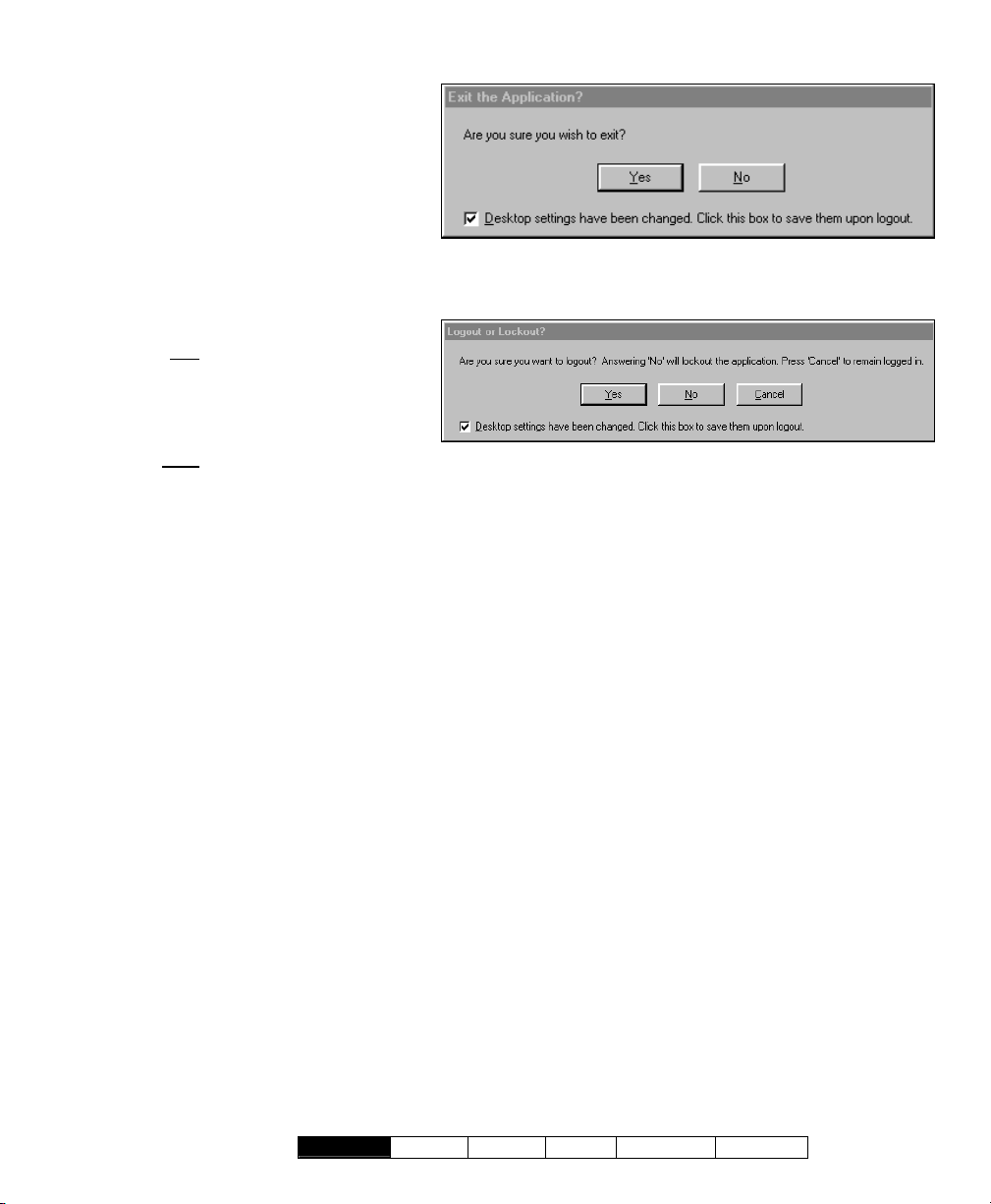
- [Yes]: Logs the present operator out,
and shuts down the VEREX Director
software.
- [No]: Aborts the exit request.
If you have changed any desktop settings, a
check-box will be provided to let you save
your settings.
- [Yes] (Logout): Logs the present
operator out, shutting down access to
the VEREX Director software.
(Until the next valid operator performs
a 'login'.)
- [No] (Lock
desktop except for the status toolbar (and login
button). (Tip: If the same operator logs back in,
the software will also remember what account
they were 'in'.)
The status toolbar requires that the software be
connected with the applicable panels. For details on
using the status toolbar, or on establishing panel
communications, refer to "Checking Status and
Controlling Items"
- [Cancel]: Aborts the logout request, leaving the
present operator logged in.
If you have changed any desktop settings, a checkbox will be provided to let you save your settings.
(For a related topic, see "The Auto-Lockout Feature",
previous.)
out): This shuts down the
(When Exiting)
Logout / Lockout
21-0381E v4.7.3
Welcome Report Control Admin Sys Config Tech-Ref
7
Page 16

The Desktop
Your 'Window' to the System
The desktop is your interface to the VEREX
Director software, providing a familiar Windows
'look and fee l', with access to all features and
items assigne d to you as a VEREX Dir ector
operator.
The VEREX Director interface can be s et as
desired by each individua l operator. This
includes whether they prefe r the MyTools bar,
or the Tree window, plus the sizing o f the
desktop sections, and other settings.
Selecting Desktop Items to be Displayed
The [Tree], [MyTools] and [Events] buttons
on the toolbar allow viewing or hiding d ifferent
aspects of the desktop (try it!).
Your MyTools Bar: You can customize the look and
content of the MyTools bar to your own preferences.
For details, refer to "Customizing the MyTools Bar".
Account-Folders
licensing, only one account will appear in the tree. In
larger systems, [Account Folders] will be shown in the
tree for operators with multi-account permissions (or
that have the authority to edit account folders).
: For systems with single-account
Saving Your Desktop Settings
After changin g an aspect of the deskto p (the
sizing, Forms/Grid mode, and/or which aspects
are to be displayed, you can save your
changes so t he desktop a ppears in the same
format the nex t t ime you lo gin. To save your
changes, op en the View menu, select
Desktop Settings, and then Save.
Tip: You will also be asked if you want to save your
changes whenever you logout or exit from the software.
Navigating the Desktop
Many screens are divided i nto 'tabs' of related
settings. (St art w ith the 'Standard' tab, and
look in any a dditional tabs that are of interest
to you.) Some screens also includ e the
familiar windows ‘scroll-bars’ whenever an item
is too large to fit on-screen.
Changing the Size of the Desktop
To resize the entire desktop, click and drag the
bottom right corner to the d esired position. (If
the screen is presently 'max imized', you'll first
need to double-click the blue title-bar, or click
the middle button in the upper right corn er of
the screen.)
To ‘max imize’ the desktop, double-click the
blue title-bar, or click the middle button in the
upper right corner of the screen.
Changing Proportions of Desktop Areas
To change the proportion of the desktop, move
the mouse to the edge of a screen area (such
as between the 'tree' and forms/grid area), and
watch for the cursor to cha nge shape. Then,
click-and-drag the edge of the window to a
new location.
Tip: You can also maximize the for m/grid
area, or the monitoring window (i.e., cause it to
fill the entire screen) by double-clicking the
title-bar for th e specific window twice
. (Also
see "Resetting...", to follow.)
Changing the Position of Desktop Items
Each portio n of the desktop can be
repositioned, and/or viewed on its own. This is
especially us eful on a multi-monitor PC,
allowing an item such as the monitoring
window to be viewed separately.
To relocate an item, 'drag-and-drop' the item
by its title-bar , while watching for the gr eyed
box indicating the new position.
To view an item 'full-screen' (such as the monitoring
window), double-click its title-bar twice. To access the
main desktop screen again, double-click the title-bar
once again.
8 VEREX Director V4.73 User's Guide 21-0381E v4.7.3
Page 17
Resetting the Desktop
After moving and resizing areas of
the screen, you may wish to reset the
desktop to e ither your last saved
settings, or to the initial factory default
layout.
Last Saved Settings
: Click Reset on
the toolbar (o r open the View menu,
and select Desktop Setti ngs, and
Reset).
Factory-Default Layout
: Open the
View menu, and sele ct Desktop
Settings, and Default).
Tip: If a window or portion of the desktop is
presently "maximized" (fills the entire
screen), you'll need to double-click its titlebar to access the menu or toolbar.
Note: If your desktop was accidentally
saved
with the monitoring window
'undocked' and hidden behind the main desktop, follow
the preceding steps for "Factory Default Layout".
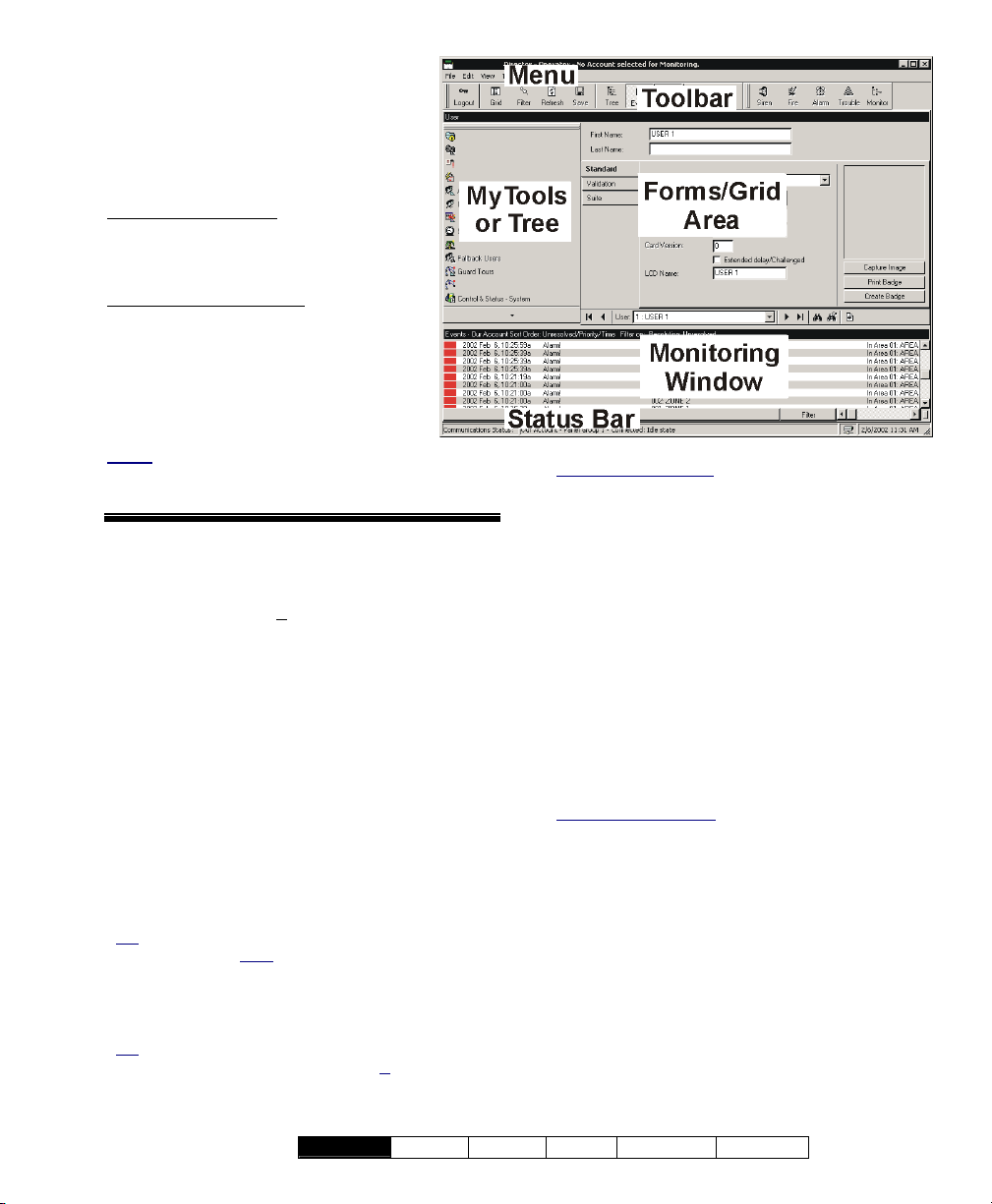
- The Menu: Provides access to some
miscellaneous features of the VEREX Director
software. Tip: The Tools menu provides
access to Wizards that simplify setting up a
new system, and/or enabling communications
with a panel.
- The Toolbar: Provides access to some
common tasks.
- The 'Tree' (optional): This is an expandable/
collapsible outline that allows selecting an
account, and provides access to most topics
including system configuration, management,
and status & control.
to view or hide the 'tree'.
Click [Tree] on the toolbar
- The 'MyTools' Bar (optional): This is a
customizable list of tasks/items that can be
used as alternative to the 'tree'.
Tip: Click [MyTools] on the toolbar to view or hide the
MyTools list/bar. Note
your operator permissions will be visible in the Tree
and MyTools Bar. As well, for items pertaining to a
specific account, you must first double-click to enter
the account.
Tip
: You can customize the look and content of the
MyTools bar when you are logged in (V
Ö Customize). For details, refer to "Customizing the
MyTools Bar".
: Only the items allowed by
iew Ö MyTools
MyTools Doesn't Work
and only a small empty 'button' appears, this means
no items are assigned to the 'MyTools' bar. See the
previous tip to fix this.
: If you select [ MyTools ],
- The Forms/Grid Area: This area shows
details on your present topic (as selected from
the tree or MyTools bar). This can be set for
either a forms view (typical / data entry), or
'grid' format (experienced persons / viewing
and sorting lists).
(Use the Form / Grid button on the toolbar to switch
views.)
- The Monitoring Window (optional): This
area shows recent events that have been
received (for a selected account).
Click [Events] on the toolbar to view or hide the
monitoring window.
Multi-Account Systems: With multiple accounts, the
monitoring window shows the events for your present
account. (Select [Account Folders] in the tree, then
locate and double-click your desired account.)
To set the account to be monitored by the status
toolbar, click [Monitor] on the far-right end of the
toolbar.
- The Status Bar: This area (at the extreme
bottom of your desktop) shows whether or not
you are connected with a selected account
(i.e., associated panels), plus other
communications-related status messages.
21-0381E v4.7.3
Welcome Report Control Admin Sys Config Tech-Ref
9
Page 18
Other Desktop Choices
Tip: You can save your desktop changes at any time:
Open the View menu, select Desktop Settings, &
Save. Note
your changes whenever you logout or exit from the
software.
Selecting Desktop Items to be Displayed
The [Tree], [MyTools] and [Events] buttons
on the toolbar allow viewing or hiding d ifferent
aspects of the desktop (try it!).
You can customize the look and content of the MyTools
bar to your own preferences . For details, refer to
"Customizing the MyTools Bar".
Setting Accounts to Appear in the Tree (Multi-Account Systems)
Account folders appear in the 'tree' (left side of
your screen), w hile account s are listed in the
centre portion of the screen, and can optionally
be set to appear in the tree as well.
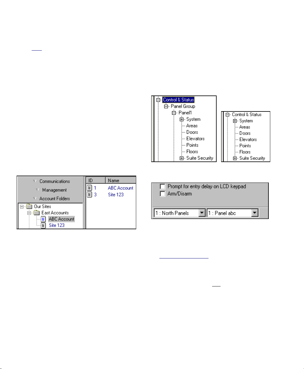
Show Accounts in Tree:
: You will also be asked if you want to save
Listing Items Panel-by-Panel vs. in a Single List and Showing or Hiding Panel References in Forms
For some tasks, you hav e two choices a s to
how items will be displaye d (in a single list,
versus panel-by-panel), and/or w hether or not
panel (and panel group) references will appear
in the form / grid portion of the desktop.
Logical Tree View?
No Yes ( 9 )
Show Panel/Panel Group Information:
Listing Configuration and Control &
To set accou nts to appear in the 'tree', click
[Account Folders] in the 'tree'. Then, right-
click within th e tree, and e nsure that Show
Accounts in Tree is selected.
Tip: This selection is also available in the View
menu when you are 'in' the Account Folders portion
of the tree.
Once you access an account (double-click the account
name), the tree will change to show the topics
associated with that specific account (admin.,
configuration, and status/control topics).
10 VEREX Director V4.73 User's Guide 21-0381E v4.7.3
Status Topics in the Tree "Panel-byPanel":
1) Click your account/site button in the tree.
Multi-Account Systems: First select [Account
Folders] in the 'tree', and double-click an account.
2) Right-click a topic in the tree (or open the
View menu), and check to ensure that
Logical Tree View is not selected.
Page 19

Listing Configuration and Control & Status Topics in the Tree as a Single List:
1) Click your account/site button in the tree.
Multi-Account Systems: First select [Account
Folders] in the 'tree', and double-click an account.
2) Right-click a topic in the tree (or open the
View menu), and check to ensure that
Logical Tree View is
selected.
To Show Panel References in the Forms/Grid Window
(This is available only when "Logical Tree View" is in
effect.)
1) Set the tree to show items in a single list (see
previous / above).
2) Open Configuration (or Control & Status) in
the tree, and select any topic (such as
"System").
3) From the View menu, select Panel
Information, and ensure that "Show Panel /
Panel-Group Information" is selected.
Tip: The "ID and Name" selection causes the
name to be included in the 'Panel' and 'Group'
columns when working in Grid view.
21-0381E v4.7.3
Welcome Report Control Admin Sys Config Tech-Ref
11
Page 20
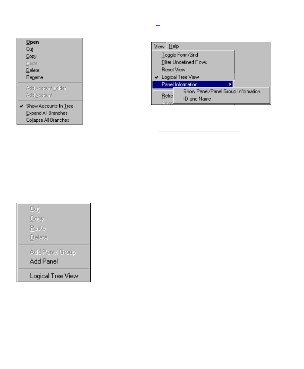
(Right-Click an Account or Folder)
- Show Accounts in Tree
Folders' portion of the tree)
between showing accounts along with the
account folders in the tree, versus showing
accounts only in the centre of the screen.
For details on adding, renaming, and deleting
accounts and account folders, refer to "Working with
Accounts and Folders".
(Right-Click within the Tree
for an Account)
(available in the 'Account
: 'Toggles' the tree
("View" menu when a Configuration
or Control & Status Topic is Selected
in the Tree)
(This is available only when "Logical Tree View" is in
effect.)
- Panel Information:
+ Show Panel / Panel-Group Information: Identifies
system panels and panel groups at the bottom of
configuration forms (and in grid view);
+ ID and Name: In conjunction with the setting
above, this shows the name for each system
panel and panel group (instead of ID only) when
working in Grid view.
In Forms view, selecting "Show Panel / Panel-Group
Information" always displays the ID and Name for the
panels & groups. (The "ID and Name" setting has no
effect when working in Forms view).
- Logical Tree View: 'Toggles' the tree between
listing all topics for an account (√) versus listing
the topics separately for each system panel (by
panel group).
Note: This setting mostly pertains to the "Control &
Status", and "Configuration" topics.
12 VEREX Director V4.73 User's Guide 21-0381E v4.7.3
Page 21

Running Reports, and Monitoring System Activity
21-0381E v4.7.3
Welcome
Report Control Admin Sys Config Tech-Ref
13
Page 22

Time-and-Attendance Reporting
In/Out Status Tracking: This feature requires "User
In/Out Status Tracking" to be enabled.
Related Setting: YourAccount, ÖAccount
Information, ÖSetup (tab), Ö"Enable User In/Out
Status for this Account"
Time and Attendance Reports
Cardholder time and attendance reporting
allows generating reports pertaining t o the
presence (roll-call), tardiness, number of hours
at w ork, etc. for users perta ining to a specific
account.
These reports are ex trapolated from entry and
exit (access g ranted) messages in the a ctivity
log, and compared against a selected
"attendance-period" that defines when the
users are supposed to be inside the facility.
TechTip: Reports pertaining to past events are based
on the present event list, plus any archived data that
has been re-imported using the archive feature.
See: "Exporting or Importing Activity or Audit Logs".
For accurate attendance reporting:
• All doors used to enter and exit the facility must
have entry and exit readers.
• The site (account) must have a ‘Required
Attendance Zone’ defined by setting the "Area" as
"Outside" for all readers used to exit
zone.
For details, refer to "Reader 1 & 2 Settings for a
Door".
• Persons must use their access card / token
EVERY time they enter and exit the facility.
Note: Persons last reported as 'In', but with no card
activity for 24 hours will be set as 'Out'.
Attendance reports can take a full minute or longer to
appear--depending on the number of cards at the site,
and the number of activity messages being scanned.
For better performance, be sure to select the smallest
date-range that meets your requirements. Also, you
can keep the activity log to a suitable size via regular
use of the Archive and/or Purge features.
For details, refer to "Exporting or Importing Activity or
Audit Logs", and "Removing old Activity or Audit Logs".
Areas set for Antipassback Checking
Reset" feature is generally not
Time & Attendance reporting functions will be used.
For details on the 'Antipassback' feature, and the "APB
Auto-Reset" selection, refer to the "Antipassback"
settings in the "Area" configuration topic.
from this
: The "APB Auto-
recommended where
Required-Attendance Time Periods
To allow time & attendance reporting, each site
(account) must have required attendance time
periods set up that specify the days and blocks
of time that employees are supposed to be
inside the facility.
For details, refer to "Required-Attendance Time
Periods".
Running a Time and Attendance Report
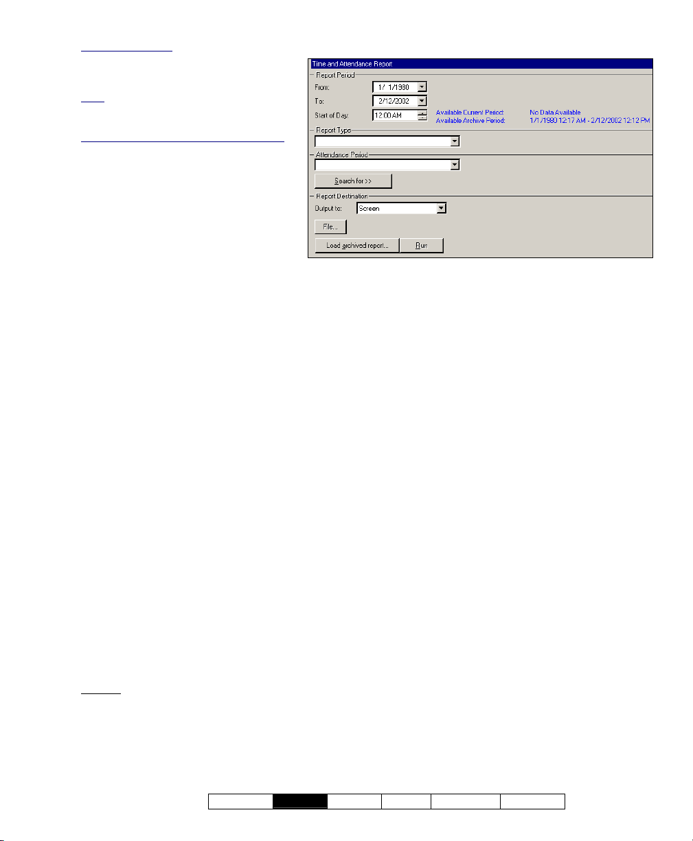
1) Select Time and Attendance Report from
your MyTools bar, or
'tree', and select Time and Attendance.
2) Multi-Account Systems: Select the desired
account near the centre of the screen.
Tip: This option appears only if you didn't already
have an account 'open' in the tree.
3) Select the range of dates to be covered by
the report ("From" and "To"), and the time to
be used as the "Start of Day".
Tip: See the item-descriptions for more info.
4) Select the desired type of report (see the
"Report Type" description for details).
5) Select the "Attendance period" that specifies
when persons are supposed to be in the
facility.
Notes: An attendance period is not required for
"Arrival / Departure", "Roll-Call" or "In/Out Status"
reports. If a suitable attendance-period is not
listed, refer to "Required-Attendance Time
Periods" to set one up now.
6) To limit the report to a specific authority,
user, etc., click [Search For], and select the
desired criteria.
Tip: To clear a selection, select it and use your
Backspace or Delete key.
Tip: You can scroll within the form to view
additional items if necessary.
7) Select a report 'destination' (i.e., whether it is
to be viewed, printed, or saved as a file).
If you select "Archive" or a type of "File",
click [File...], set the location and filename
as desired, and click Save.
8) Click [Run], and respond to any additional
screen(s) that appear (details to follow).
For details on viewing and printing displayed reports,
refer to "Working with the Report Viewer".
click [Reports] in the
14 VEREX Director V4.73 User's Guide 21-0381E v4.7.3
Page 23

If Printing an Attendance Report
To print a report without viewing it first: Select
the type of report and other criteria as usual,
and select Printer as the destination. Then,
select Run, and click OK w hen the 'Print'
screen appea rs. Tip: To select a dif ferent
printer click Printer, and make your se lection
from the 'Print Setup' screen that appears.
To view a report before prin ting
: Select the
type of report and other criteria as usua l,
and select ' Screen' as t he destination.
Then, click Run.
For details on vie wing an d printing the
displayed report, refer to " Working with the
Report Viewer".
If Exporting an Attendance Report as a File (Archive/Text File/Report Emulation File)
Select the typ e of report an d other criteri a as
usual, and the desired file-type a s the
'destination'. Then, click [File...]. In the next
screen, set the location and filena me as
desired, and click Save when finished. Then
click Run.
Viewing/Printing a Previously Saved Attendance Report-Archive
Select Time and Atten dance Repor t from
your MyTools bar, or
click [Repor ts] in the
'tree', and s elect Time and Attendance.
Then, click [Load ar chived r eport] at the
bottom of the form (scroll down if necessary).
Multi-Account Systems: You do not have to select an
account since that was done when the report was
archived.
In the ne xt screen, locat e and sele ct the
desired archived report ( .raf), and click Open
(or simply double-click the file).
For details on viewing and printing displayed reports,
refer to "Working with the Report Viewer".
21-0381E v4.7.3
Welcome
Report Control Admin Sys Config Tech-Ref
15
Page 24

Report Period
- From and To (date): The beginning and end
date from the event log to be checked for
cardholder activity. (Change the values
manually, or click the arrow to access a pop-up
calendar.)
Note: Roll-call and In/Out status reports use the
previous 48 hours as a date/time range (instead of the
"From" and "To" settings).
- Start of Day: This setting allows shifts that
span midnight to be handled properly. Leave
this as 12:00 AM for all work shifts that begin
and end on the same day. For a shift that spans
midnight, select a time at some midpoint
between the end of one shift and the beginning
of the next one (perhaps 1:00 PM).
Report Type
(and Strict Interval / Relaxed Interval)
- Absentee: Persons who were not present
during some part of each specific time interval of
the required-attendance period.
Exception: With "Relaxed Interval", only persons
absent for the whole day are listed (if two intervals,
both will be reported the same).
- Arrival/Departure: The time of the first arrival
and last departure for all persons present on
each day covered by the report.
- Early Departure: Persons who left before the
end of one or more time intervals of the
required-attendance period.
Note: With "Strict Interval", persons who leave during
a required time-interval, and then return after-hours
(on the same workday) are treated as early
departures. Select "Relaxed Interval" to stop this.
- Late Arrival: Persons who arrived after the
beginning of one or more time intervals of the
required-attendance period.
Note: With "Strict Interval", persons who arrive and
leave beforehand (on the same workday) and then
return during a required time interval are treated as
late arrivals. Select "Relaxed Interval" to stop this.
- Totalization: The duration each person spent
inside the facility on each day during the
required-attendance times.
- Roll Call: All persons presently tracked as
being inside the facility's required-attendance
zone
(see note);
v4.61: After selecting "Report Type: Roll Call", select
"System" (system-wide), or an individual area, as
desired. (If you select "System", the report will list
persons on an area-by-area basis.)
- In/Out Status: A list of all users, showing
whether they are presently tracked as being
inside or outside of the facility's requiredattendance zone (see note).
Tip: Persons last reported as 'In', but with no card
activity for 24 hours will be set as 'Out'.
Note: For details on setting up a ‘Required
Attendance Zone’, refer to "Reader 1 & 2 Settings for
a Door".
Attendance Period
A time period (previously-defined) that specifies
when persons are required to be inside the
facility.
An attendance period is not required for
"Arrival/Departure", "Roll-Call" or "In/Out Status"
reports. To set up an attendance period, refer to
"Required-Attendance Time Periods".
[Search For] / [Clear Search]
- This displays or closes the centre of the screen,
which contains selections for 'fine-tuning' the
report to a specific person, or users with a
certain authority-profile or other criteria.
To clear a selection: Select it and use your
Backspace or Delete key.
Searching by Name
by user-name, you can enter the 1st or
only, 1st and
"LastName,
name, you can enter the first few characters plus an
asterisk (e.g., nam*).
: For reports that allow searching
last name
last name (separated with a space), or
1stName". If searching for a first or last
16 VEREX Director V4.73 User's Guide 21-0381E v4.7.3
Page 25
Custom User Field: This pertains to
(optional) custom user information
categories that can appear at the bottom of
the 'User' screen.
Note
: Reports cannot be filtered on multiline fields. Be sure to make your selection
with this in mind.
Past Employees Deleted from the System
You can type a name rather than selecting
it. This allows running a report on persons
(and/or items) that have been recently
deleted.
Reports ÖTime and Attendance
:
Report Destination / Output To
- Screen: This has the report sent to the
'Report Viewer' window for viewing
and/or printing desired pages;
- Printer: This allows selecting a printer
and page-range, etc., and printing the
report (without viewing it first);
- Text File: This has the report saved
(Multi-Account Systems: Account Selection 'Tree')
- This area (near the centre of the screen) is where you select the
account that your report pertains to. Tip: This option appears only if
you didn't already have an account 'open' in the tree.
as a 'comma-delimited' text file for
manipulation with another program. Allows you
to change the location and/or filename if
desired.
- Report Emulation Text File: This has the
report saved as a formatted text file for viewing,
printing, or editing with a text editor or word
processor. Allows you to change the location
and/or filename if desired.
- Archive: This has the report saved as a
viewable archived report for viewing or printing
at a later time. Allows you to change the
location and/or filename if desired.
(Remaining Buttons)
(You may need to scroll within the form and/or resize
the window to view additional items. Click Reset on the
toolbar to reset the desktop.)
- [File...]: This allows changing the location and
file-name for a report being saved for future
viewing, printing, etc. Tip: Use a different
name each time to avoid overwriting previous
reports.
- [Load Archived Report]: This allows browsing
for, and opening a previously saved reportarchive
(not for use with text files). The report
will appear in the report-viewer window for
viewing and/or printing.
For details on viewing and printing displayed reports,
refer to "Working with the Report Viewer".
- [Run]: This runs the report based on your
selected criteria. Additional screens will appear
depending on your selections (such as the
printer selection form, report viewer, etc.).
21-0381E v4.7.3
Welcome
Report Control Admin Sys Config Tech-Ref
17
Page 26

Required-Attendance Time-Periods
Attendance Periods
Attendance p eriods are w eekly blocks of time
that allow tim e & attendance reports to 'k now'
when users are supposed to be in the facility.
Schedules for cardholder access must span a larger
period of time than the applicable attendance period--to
let people enter the facility before their shift begins, and
leave after it ends.
Adding (Setting up) an Attendance Period
Select Attendance Period from your MyTools
click [Repor ts] in the 'tree', open the
bar, or
Time and Attendance branch, and select
Attendance Period.
Multi-Account Systems: Select the desired account
near the centre of the screen. Tip: This option
appears only if you didn't already have an account
'open' in the tree.
Now, cli ck [+] at the botto m of the for m, or
right-click the form, and select Add Ne w from
the pop-up menu.
Alternative: You can also select a blank/grey item from
the list (bottom of the form). Note
apply to this screen.
: Grid view does not
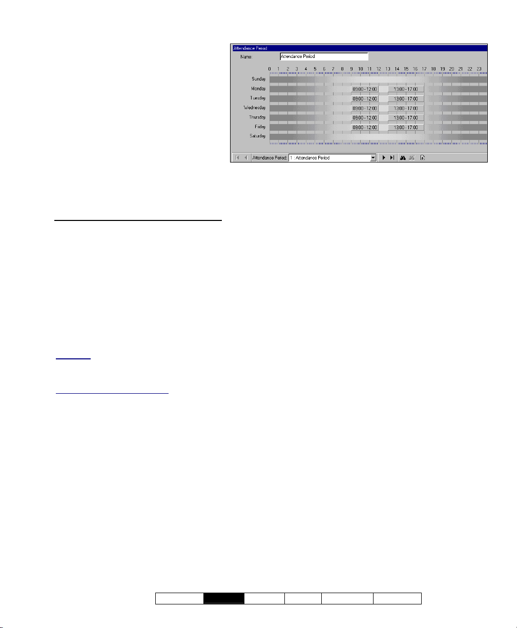
The attendance period is shown graphically,
for Sunday through Saturday. Add a new timeinterval by right-clicking a specific day, and
selecting Create New Time Interval.
Then, drag the interval and/or its end-poin ts to
the desired lo cation. Tip: Copying, pa sting,
and deleting is also allo wed w hen you r ightclick a specific time-interval.
Repeat this process until the desired times are
set up for all days in the attendance period.
(You can use up to 6 uni que time intervals
throughout each schedule.)
Now refer to t he selection-descriptions for this
screen for additional information.
Tip: You can copy all settings for an attendance
period, and paste them into another one: In the 1
right-click near the bottom of the form, and select Copy.
Then, select a blank/new attendance period from the
list, right-click near the bottom of the form, and select
Paste. After 'pasting', change the name and any
settings as desired. Note: 'C
available from the E
dit menu.
opy' and 'Paste' are also
st
one,
Viewing or Changing Settings for a Required-Attendance Period
Select Attendance Period from your MyTools
bar, or
click [Repor ts] in the 'tree', open the
Time and Attendance branch, and select
Attendance Period.
Multi-Account Systems: Select the desired account
near the centre of the screen.
Now, choos e the desired attendance p eriod
from the list ( bottom of the form), and refer to
the selection-descriptions for this screen while
viewing and/or changing settings as desired.
Deleting an Attendance Period
Select Attendance Period from your MyTools
bar, or
click [Repor ts] in the 'tree', open the
Time and Attendance branch, and select
Attendance Period.
Multi-Account Systems: Select the desired account
near the centre of the screen.
Now, choos e the desired attendance p eriod
from the list ( bottom of the form). Then, rightclick a blank area near the bottom, and select
Delete. When asked to confirm, choose Yes.
18 VEREX Director V4.73 User's Guide 21-0381E v4.7.3
Page 27
Reports ÖTime and Attendance ÖAttendance Period
Pick-Lists (bottom of the
Form)
- Attendance Period (bottom of form):
This is where you select an attendance
period to view or edit. This area
shows a reference number assigned
by the system, and the name of the
attendance period, once defined;
Top of the Form
- Name: A suitable name/description for
the attendance period, or its intended
use;
(Multi-Account Systems: Account Selection 'Tree')
- This area (near the centre of the screen) is where you select the
account that your attendance-period pertains to. Tip: This option
appears only if you didn't already have an account 'open' in the tree.
On this Form (Intervals )
- Days of the Week (with Associated Time-
Intervals): The days of the week showing the
time intervals for each day. (To add an
interval, right-click the specific day. To adjust
an interval, drag the interval and/or its endpoints to the desired position.)
Tips: You can copy and paste (or delete) time
intervals using the right-click menu. Up to 6 unique
time-intervals can be used as desired throughout the
weekdays in each attendance period.
Split Shift
meal break—assuming the break is not part of the
'required attendance' times.
Work Shift that Spans Midnight
will need two intervals for the times before and after
midnight, plus any other required intervals (such as for
after a meal break—assuming the break is not part of
the 'required attendance' times).
: Be sure to include an interval for after a
: In this case, each day
21-0381E v4.7.3
Welcome
Report Control Admin Sys Config Tech-Ref
19
Page 28
Roll-Call Reports (v4.61)
In/Out Status Tracking: This feature
requires "User In/Out Status Tracking" to be
enabled.
Related Setting: YourAccount, ÖAccount
Information, ÖSetup (tab), Ö"Enable User
In/Out Status for this Account"
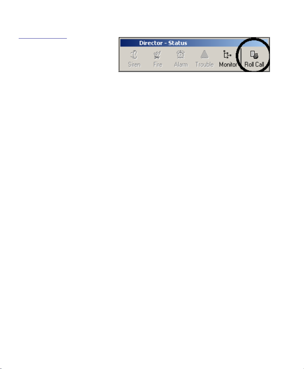
An instant roll-call feature has been
added to the status toolbar.
This sends a roll-call report for your
monitored account to your default Windows
printer.
(The report will list persons on an area-byarea basis.)
Note: A communications session with the
applicable panel(s) must be in effect.
To start a communications session:
1) Select Communications from your MyTools bar, or
click [Communications] in the 'tree', and select
Pending/OnLine. 2) Click [Edit], and make your
selections from the screen that appears.
Tip: Once there, you can open the online help at the
applicable topic by pressing F1.
To set or change the account to be monitored:
1) Click [Monitor] near the far-right end of the toolbar;
2) Make your selections from the screen that appears.
To select a default printer under MS Windows:
1) Go to your Windows "Control Panel"; 2) Double-click
"Printers and Faxes"; 3) Double-click the desired
printer.
As well, "Time and Attendan ce - Rol l-Call"
reports can now be run on individual areas.
20 VEREX Director V4.73 User's Guide 21-0381E v4.7.3
Page 29

Reporting on System & Personnel Activity
Activity Reports
Activity reporting allo ws vie wing or printing a
listing of various types of events that have
occurred for a specific a ccount. A date /time
range can be specified, and the report can also
be limited to a specific are a, device, per son,
etc.
TechTip: Reports pertaining to past events are based
on the present event list, plus any archived data that
has been re-imported using the archive feature.
See: "Exporting or Importing Activity or Audit Logs".
As well, activity reports can be vie wed a nd/or
printed right a way, saved for future reference,
or ex ported for manipulation w ith ano ther
program.
For better performance, activity reports cover only the
latest 5000 messages in the activity log. For even
faster execution, keep the activity log to a suitable size
via regular use of the Archive and/or Purge features.
See: "Exporting or Importing Activity or Audit Logs",
and "Removing old Activity or Audit Logs".
Running an Activity Report
1) Select Activity Report from your MyTools
bar, or
click [Reports] in the 'tree', and select
Activity.
2) Multi-Account Systems: Select the desired
account near the centre of the screen.
Tip: This option appears only if you didn't already
have an account 'open' in the tree.
3) Select the date/time range to be covered by
the report (under "From" and "To").
Tip: See the item-descriptions if you need help.
4) Select the types of events to be included in
the report (you must select at least one).
5) To limit the report to a specific person, area,
door, etc., click [Search For], and select the
desired criteria.
To clear an individual selection, select it and use
your Backspace or Delete key. To reset/clear all
selections, scroll down and click [Reset].
Tip: You can scroll within the form to view
additional items if necessary.
6) Select a report 'destination' (i.e., whether it is
to be viewed, printed, or saved as a file).
If you select "Archive" or a type of "File", click
[File...], set the location and filename as
desired, and click Save.
7) Click [Run], and respond to any additional
screen(s) that appear (details to follow).
For details on viewing and printing displayed reports,
refer to "Working with the Report Viewer".
If Printing an Activity Report
To print a report without viewing it first: Select
the type of report and other criteria as usual,
and select Printer as the destination. Then,
select Run, and click OK w hen the 'Print'
screen appea rs. Tip: To select a dif ferent
printer click Printer, and make your se lection
from the 'Print Setup' screen that appears.
To view a report before prin ting
type of report and other criteria as usua l,
and select ' Screen' as t he destination.
Then, click Run.
For details on vie wing an d printing the
displayed report, refer to " Working with the
Report Viewer".
If Exporting an Activity Report as a File (Archive/Text File/Report Emulation File)
Select the typ e of report an d other criteri a as
usual, and the desired file-type a s the
'destination'. Then, click [File...]. In the next
screen, set the location and filena me as
desired, and click Save when finished. Then
click Run.
Viewing/Printing a Previously Saved Activity Report-Archive
Select Activity Report from your MyTools bar,
or
click [Repor ts] in the 'tree', and select
Activity. The n, click [Load ar chived r eport]
at the botto m of the form (scroll dow n if
necessary).
Multi-Account Systems: You do not have to select an
account since that was done when the report was
archived.
In the ne xt screen, locat e and sele ct the
desired archived report ( .raf), and click Open
(or simply double-click the file).
For details on viewing and printing displayed reports,
refer to "Working with the Report Viewer".
: Select the
21-0381E v4.7.3
Welcome
Report Control Admin Sys Config Tech-Ref
21
Page 30

Event Period
- From and To (date and time): The beginning
and end date from the event log to be checked
for cardholder activity.
Tip: You can change the dates manually, or click the
arrow to access a pop-up calendar. To set the times,
click within the 'hours' or 'minutes', and use the
up/down arrow keys.
Event Type
- The various types of messages that can be
included in the report (select the ones that you
want included).
Note: You must select at least one event-type.
"Toggle All" allows selecting or de-selecting all eventtypes.
[Search For] / [Clear Search]
- This displays or closes the centre of the screen,
which contains selections for 'fine-tuning' the
report to a specific person, area, door, etc.
Custom User Field: This pertains to (optional) custom
user information categories that can appear at the
bottom of the 'User' screen.
Note
: Reports cannot be filtered on multi-line fields.
Be sure to make your selection with this in mind.
Show on Resolution
events depending on whether or not they have been
'resolved' (i.e., dealt-with). "All": This shows all
events--including ones not associated with the
comment/resolution feature.
For details on resolving events, refer to "Dealing with
Alarms (Comment / Resolve)" in the section on
monitoring activity (previous).
Show on Priority
show only events of a desired priority value (or range).
Show on Custom Filter
window to show only events of a desired 'custom-filter'
value (or range).
Also See: To assign priorities or 'Custom Filter'
values, refer to the configuration topic: "Customizing
How Events are Displayed".
Tip: To clear an individual selection, select it and use
your Backspace or Delete key. To reset/clear all
selections, click the [Reset] button at the bottom of
the form (scroll down if this button is not visible).
Past Employees Deleted from the System
type a name rather than selecting it. This allows
running a report on persons (and/or items) that have
been recently deleted.
: This lets you have the list include
: This allows limiting the window to
: This allows limiting the
: You can
Report Destination / Output To
- Screen: This has the report sent to the 'Report
Viewer' window for viewing and/or printing
22 VEREX Director V4.73 User's Guide 21-0381E v4.7.3
Page 31
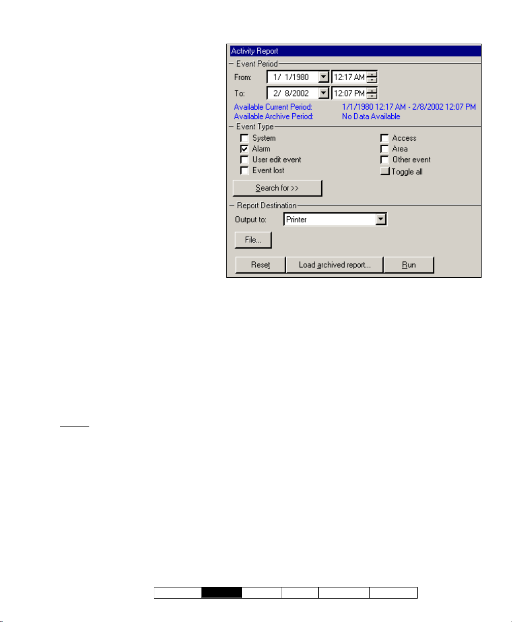
desired pages;
Reports ÖActivity
- Printer: This allows selecting a printer
and page-range, etc., and printing the
report (without viewing it first);
- Text File: This has the report saved
as a 'comma-delimited' text file for
manipulation with another program.
Allows you to change the location
and/or filename if desired.
- Report Emulation Text File: This has
the report saved as a formatted text
file for viewing, printing, or editing with
a text editor or word processor.
Allows you to change the location
and/or filename if desired.
- Archive: This has the report saved as
a viewable archived report for viewing
or printing at a later time. Allows you
to change the location and/or filename
if desired.
(Remaining Buttons)
Tip: You can scroll within the form and/or
resize the window to view additional items
when necessary. (Click Reset on the
toolbar to reset the desktop.)
- [File...]: This allows changing the
location and file-name for a report
being saved for future viewing,
printing, etc. Tip: Use a different name each
time to avoid overwriting previous reports.
- [Reset]: This provides a quick way to reset/clear
the "Search for" criteria and other selections on
the form.
- [Load Archived Report]: This allows browsing
for, and opening a previously saved reportarchive
(not for use with text files). The report
will appear in the report-viewer window for
viewing and/or printing.
For details on viewing and printing displayed reports,
refer to "Working with the Report Viewer".
- [Run]: This runs the report based on your
selected criteria. Additional screens will appear
depending on your selections (such as the
printer selection form, report viewer, etc.).
(Multi-Account Systems: Account Selection 'Tree')
- This area (near the centre of the screen) is where you select the
account that your report pertains to. Tip: This option appears only if
you didn't already have an account 'open' in the tree.
21-0381E v4.7.3
Welcome
Report Control Admin Sys Config Tech-Ref
23
Page 32

Reporting on Previous Guard-Tours
Guard Tour Reports
Guard tour reports allo w view ing or print ing a
listing of events pertaining to previous guard
tours for a specific account. A date/time range
can be specif ied, and the r eport can als o be
limited to sp ecific items s uch as guard tour
alarms, or the guard arriving early or late.
TechTip: Reports pertaining to past events are based
on the present event list, plus any archived data that
has been re-imported using the archive feature.
See: "Exporting or Importing Activity or Audit Logs".
Active Guard Tours
tour, refer to "Guard Tours".
: For details on monitoring a guard-
As well, guar d tour reports can be vie wed
and/or printe d right aw ay, saved for f uture
reference, or e xported for manipulation with
another program.
For better performance, activity and guard-tour reports
cover only the latest 5000 messages in the activity log.
For even faster execution, keep the activity log to a
suitable size via regular use of the Archive and/or
Purge features.
See: "Exporting or Importing Activity or Audit Logs",
and "Removing old Activity or Audit Logs".
Running a Guard Tour Report
1) Select Guard Tour Report from your
MyTools bar, or
and select Guard Tour.
2) Multi-Account Systems: Select the desired
account near the centre of the screen.
Tip: This option appears only if you didn't already
have an account 'open' in the tree.
3) Select the date/time range to be covered by
the report (under "From" and "To").
Tip: See the item-descriptions if you need help.
4) Select the types of events to be included in
the report (you must select at least one).
5) Select a report 'destination' (i.e., whether it is
to be viewed, printed, or saved as a file).
If you select "Archive" or a type of "File", click
[File...], set the location and filename as
desired, and click Save.
6) Click [Run], and respond to any additional
screen(s) that appear (details to follow).
For details on viewing and printing displayed reports,
refer to "Working with the Report Viewer".
click [Reports] in the 'tree',
If Printing a Guard Tour Report
To print a report without viewing it first: Select
the type of report and other criteria as usual,
and select Printer as the destination. Then,
select Run, and click OK w hen the 'Print'
screen appea rs. Tip: To select a dif ferent
printer click Printer, and make your se lection
from the 'Print Setup' screen that appears.
To view a report before prin ting
: Select the
type of report and other criteria as usua l,
and select ' Screen' as t he destination.
Then, click Run.
For details on vie wing an d printing the
displayed report, refer to " Working with the
Report Viewer".
If Exporting a Guard Tour Report as a File (Archive/Text File/Report Emulation File)
Select the typ e of report an d other criteri a as
usual, and the desired file-type a s the
'destination'. Then, click [File...]. In the next
screen, set the location and filena me as
desired, and click Save when finished. Then
click Run.
Viewing/Printing a Previously Saved Guard Tour Report-Archive
Select Guard Tour Report from your MyTools
click [Reports] in the 'tree', and select
bar, or
Guard Tour . Then, clic k [Load archi ved
report] at the bottom of the form.
Multi-Account Systems: You do not have to select an
account since that was done when the report was
archived.
In the ne xt screen, locat e and sele ct the
desired archived report ( .raf), and click Open
(or simply double-click the file).
For details on viewing and printing displayed reports,
refer to "Working with the Report Viewer".
24 VEREX Director V4.73 User's Guide 21-0381E v4.7.3
Page 33
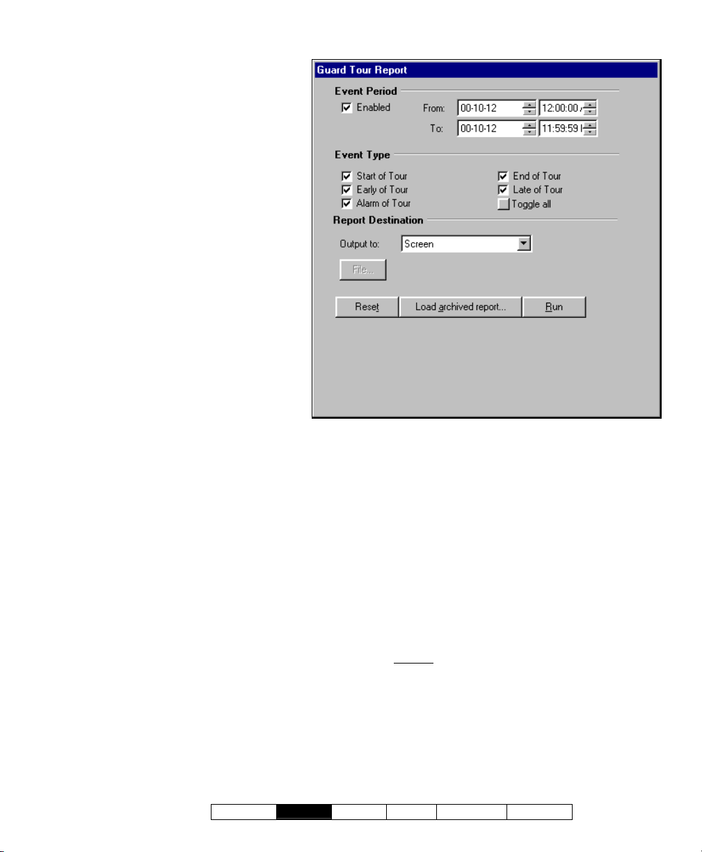
Reports ÖGuard Tour
Event Period
- From and To (date and time): The
beginning and end date from the event
log to be checked for guard-tour
events.
Tip: You can change the dates manually,
or click the arrow to access a pop-up
calendar. To set the times, click within the
'hours' or 'minutes', and use the up/down
arrow keys.
Event Type
- The various guard tour events to be
included in the report (the guard
arriving late, etc.). Select the ones
that you want included).
Note: You must select at least one eventtype. "Toggle All" allows selecting or deselecting all event-types.
Report Destination / Output To
- Screen: This has the report sent to the
'Report Viewer' window for viewing
and/or printing desired pages;
- Printer: This allows selecting a printer
and page-range, etc., and printing the
report (without viewing it first);
- Text File: This has the report saved
as a 'comma-delimited' text file for
manipulation with another program.
Allows you to change the location and/or
filename if desired.
- Report Emulation Text File: This has the
report saved as a formatted text file for viewing,
printing, or editing with a text editor or word
processor. Allows you to change the location
and/or filename if desired.
- Archive: This has the report saved as a
viewable archived report for viewing or printing
at a later time. Allows you to change the
location and/or filename if desired.
(Multi-Account Systems: Account Selection 'Tree')
- This area (near the centre of the screen) is where you select the
account that your report pertains to. Tip: This option appears only if
you didn't already have an account 'open' in the tree.
(Remaining Buttons)
- [File...]: This allows changing the location and
file-name for a report being saved for future
viewing, printing, etc. Tip: Use a different
name each time to avoid overwriting previous
reports.
- [Reset]: This provides a quick way to reset/clear
all selected items on the screen.
- [Load Archived Report]: This allows browsing
for, and opening a previously saved report-
(not for use with text files). The report
archive
will appear in the report-viewer window for
viewing and/or printing.
For details on viewing and printing displayed reports,
refer to "Working with the Report Viewer".
- [Run]: This runs the report based on your
selected criteria. Additional screens will appear
depending on your selections (such as the
printer selection form, report viewer, etc.).
21-0381E v4.7.3
Welcome
Report Control Admin Sys Config Tech-Ref
25
Page 34

Reporting on User Access Authorities (by Area, Door, or Floor)
User Access Reports
User-access reports provide a list of the
persons with authority to access a specific
area, door, or floor on spec ific weekdays and
times. You can also list: • Cards that have
expired; • Cards that w ill ex pire in the future
(selectable date-range); • Cards that have not
been used since a specific date; • Cards
identified as being 'Lost'.
Related: Users, ÖLost Cards
Cards that have been Lost
Tip: This is a powerful report that checks more than
schedules and area assignments. It also checks things
like "Master Override", scheduled door unlockings, etc.
Note: This report pertains to users who are intended
to have access based on system configuration. (It
cannot allow for things such as manual door
unlockings.)
User-access reports can be vie wed a nd/or
printed right a way, saved for future reference,
or ex ported for manipulation w ith ano ther
program.
To view a report before prin ting
type of report and other criteria as usua l,
and select ' Screen' as t he destination.
Then, click Run.
For details on vie wing an d printing the
displayed report, refer to " Working with the
Report Viewer".
If Exporting a Report as a File
(Archive/Text File/Report Emulation File)
Select the typ e of report an d other criteri a as
usual, and the desired file-type a s the
'destination'. Then, click [File...]. In the next
screen, set the location and filena me as
desired, and click Save w hen finis hed.
Then click Run.
Viewing/Printing a Previously Saved Report-Archive
Select User Access Report from your
MyTools bar, or
click [Rep orts] in the 't ree',
: Select the
and select User Acce ss. Then, click [Load
Running a User-Access Report
1) Select User Access Report from your
MyTools bar, or
click [Reports] in the 'tree',
and select User Access.
2) Multi-Account Systems
: Select the desired
account near the centre of the screen.
Tip: This option appears only if you didn't already
have an account 'open' in the tree.
3) Refer to the selection-descriptions for this
screen while setting up your report as
desired.
4) Click [Run], and respond to any additional
screen(s) that appear (details to follow).
For details on viewing and printing displayed reports,
refer to "Working with the Report Viewer".
If Printing a User-Access Report
To print a report without viewing it first: Select
the type of report and other criteria as usual,
and select Printer as the destination. Then,
select Run, and click OK w hen the 'Print'
screen appea rs. Tip: To select a dif ferent
printer click Printer, and make your se lection
from the 'Print Setup' screen that appears.
archived rep ort] at the b ottom of the form
(scroll down if necessary).
Multi-Account Systems: You do not have to select an
account since that was done when the report was
archived.
In the ne xt screen, locat e and sele ct the
desired archived report ( .raf), and click Open
(or simply double-click the file).
For details on viewing and printing displayed reports,
refer to "Working with the Report Viewer".
Report Type
- Select the type of information to be included in
your report.
User Access to Area/Door/Floor: This lists
users/cards that have access to a specific area, door,
or floor during selected days and times.
Expired Cards
expired, or that will expire in the future (per your
selections). Tip: You can change the date numerals
manually, or click the arrows to access pop-up
calendars.
Inactive Cards
used since a selected date. Tip: You can change the
date numerals manually, or click the arrow to access a
pop-up calendar.
: This lists cards that are presently
: This lists cards that have note been
26 VEREX Director V4.73 User's Guide 21-0381E v4.7.3
Page 35
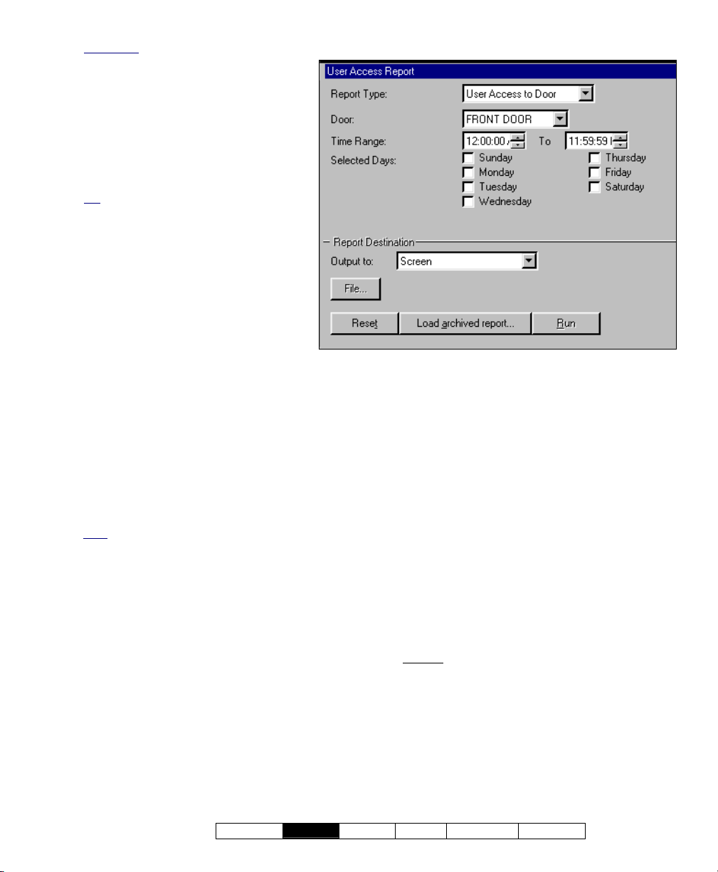
Lost Cards: This lists cards that have been
identified as 'lost'. User names and IDs will
be included in the report for cards set as
'Lost' through the "Users" screen.
Related: Users, ÖLost Cards
Cards that have been Lost
Reports ÖUser Access
Time Range
- Select the time of day to be examined
for cardholder access (i.e., the starting
time and end time).
Tip: To set the times, click within the
'hours' or 'minutes', and use the up/down
arrow keys. Note: The report will include
everyone with access during any portion
of your selected time range.
Selected Days
- Select the weekdays to be examined
for cardholder access.
Note: You must select at least one
weekday. Note: The report will include
everyone with access on any of the days
you select.
- Area is not scheduled, list users
with access when area is off: This
causes the report to disregard if the
(Multi-Account Systems: Account Selection 'Tree')
- This area (near the centre of the screen) is where you select the
account that your report pertains to. Tip: This option appears only if
you didn't already have an account 'open' in the tree.
area is presently armed.
- Process Authority Plus: Select this for users
that may have a second authority assigned
(authority plus).
- Custom User Field x: This allows selecting
one or two custom user fields to be included in
the report.
Note: These cannot be multi-line fields.
Report Destination / Output To
- Screen: This has the report sent to the 'Report
Viewer' window for viewing and/or printing
desired pages;
- Printer: This allows selecting a printer and
page-range, etc., and printing the report (without
viewing it first);
- Text File: This has the report saved as a
'comma-delimited' text file for manipulation with
another program. Allows you to change the
location and/or filename if desired.
- Report Emulation Text File: This has the
report saved as a formatted text file for viewing,
printing, or editing with a text editor or word
processor. Allows you to change the location
and/or filename if desired.
- Archive: This has the report saved as a
21-0381E v4.7.3
Welcome
Report Control Admin Sys Config Tech-Ref
viewable archived report for viewing or printing
at a later time. Allows you to change the
location and/or filename if desired.
(Remaining Buttons)
- [File...]: This allows changing the location and
file-name for a report being saved for future
viewing, printing, etc. Tip: Use a different
name each time to avoid overwriting previous
reports.
- [Reset]: This provides a quick way to reset/clear
the "Search for" criteria and other selections on
the form.
- [Load Archived Report]: This allows browsing
for, and opening a previously saved reportarchive
will appear in the report-viewer window for
viewing and/or printing.
For details on viewing and printing displayed reports,
refer to "Working with the Report Viewer".
- [Run]: This runs the report based on your
selected criteria. Additional screens will appear
depending on your selections (such as the
printer selection form, report viewer, etc.).
(not for use with text files). The report
27
Page 36

Reporting on Users, System/Device Settings, etc.
Customizable Reports
The VEREX Director soft ware allo ws vie wing
or printing a listing of programmed information
in your syste m. This inc ludes settings for the
system, areas, devices, panel users, etc.
Related Topic: You can also link to the database and
set up custom queries of nearly any scope and content.
Details: Advanced Database Features
These report s sho w a lis t of your selected
items, in a customizable format:
• Set the fields/settings to appear in the report,
and the order of these 'columns';
• Include only the users/items that match
specific criteria;
• Set the sort order for the listed users/items.
Tip: These reports can also be saved as a 'commadelimited' text file for manipulation with another
program.
Running these Types of Reports
1a) To view or print a customizable list of users,
select User Report from your MyTools bar,
or click [Reports] in the 'tree', and select
Users .
1b) For a customizable list of other programmed
items, select Panel Configuration Report
from your MyTools bar, or click [Reports] in
the 'tree', and select Panel Configuration.
2) Multi-Account Systems: Select the desired
account in the account selection 'tree' near
the centre of the screen.
Tip: This option appears only if you didn't already
have an account 'open' in the tree.
3) Panel Configuration Reports: Select the
"Type" of report (e.g., list settings for areas,
doors, schedules, etc.).
4) Select the columns of items to be included in
the report ( 9 ).
Tip: For more information, refer to "Columns" in
the selection-descriptions.
5) Select a report 'destination' (i.e., whether the
report is to be viewed, or printed without
viewing it first).
Tip: If saving a report as a text file, click [File...],
set the location and filename as desired, and click
Save.
6) Click [Run], and respond to any additional
screen(s) that appear (details to follow).
28 VEREX Director V4.73 User's Guide 21-0381E v4.7.3
For details on viewing and printing displayed reports,
refer to "Working with the Report Viewer".
If Printing one of These Reports
To print a report without viewing it first: Select
the type of report and other criteria as usual,
and select Printer as the destination. Then,
select Run, and click OK w hen the 'Print'
screen appea rs. Tip: To select a dif ferent
printer click Printer, and make your se lection
from the 'Print Setup' screen that appears.
To view a report before prin ting
: Select the
type of report and other criteria as usua l,
and select ' Screen' as t he destination.
Then, click Run.
For details on vie wing an d printing the
displayed report, refer to " Working with the
Report Viewer".
If Exporting one of these Reports as a Text File
Select "User", and set t he 'destinatio n' as
"Text File ". Then, click [File...]. In the nex t
screen, set the location and filena me as
desired, and click Save w hen finis hed.
Then click Run.
Tip: The report will be saved as a 'comma-delimited'
text file that can be manipulated with another program
as desired.
Viewing/Printing a Previously Saved Report-Archive
Select the de sired type of r eport as desc ribed
previously ("Users", or "Panel Configuration").
Then, click [Load ar chived r eport] at the
bottom of the form.
Multi-Account Systems: You do not have to select an
account since that was done when the report was
archived.
In the ne xt screen, locat e and sele ct the
desired archived report ( .raf), and click Open
(or simply double-click the file).
For details on viewing and printing displayed reports,
refer to "Working with the Report Viewer".
Page 37
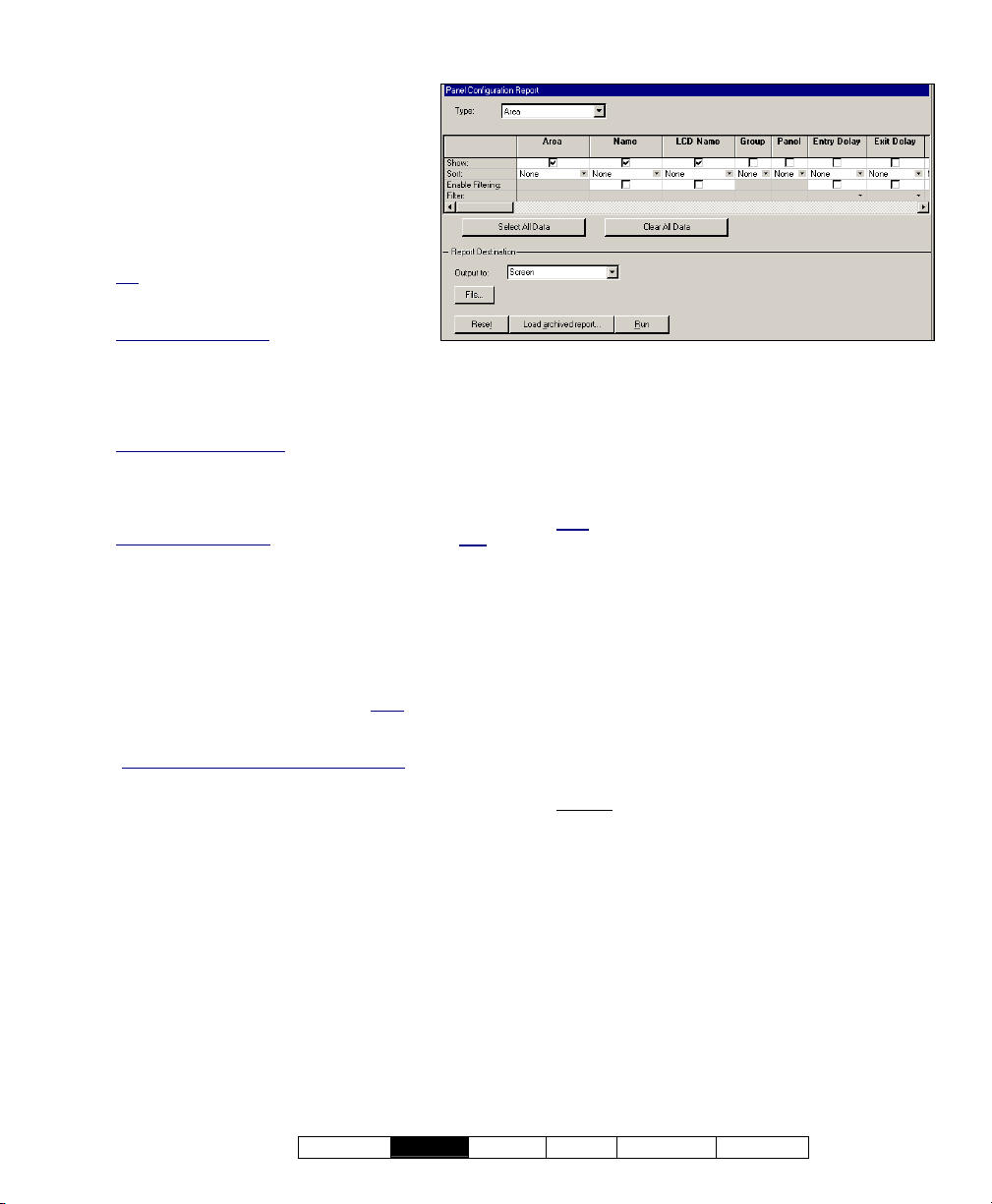
- Type (Panel Config. Reports only):
Reports ÖUsers; Reports ÖPanel Configuration
The desired topic to be covered by the
report (areas, doors, etc.).
Note: Reports pertaining to "Areas" and
physical devices (modules, doors, etc.) are
available only for operators with the
applicable 'Configuration' permissions.
- (Columns): Data fields/settings to be
included in the report.
Tip: The "Group" column in panel config.
reports pertains to the "Panel Group" (e.g.,
location) for the specific panel.
Set the Column Order
position of a column, click the column once
to select it, and then click-and-drag it to the
new location. Tip: You can use the
horizontal scroll-bar to view additional
columns.
Select Desired Columns
box for each column to appear in the report ( 9 ).
Tip: You will be notified if you selected more than
can fit in the space available (de-select some if
required).
Setting the Sort-Order
value (such as last name), open the 'sort' box for the
desired column (click the down arrow), and select the
desired sort order (ascending or descending).
Limiting to People/Items that match some Criteria: To
limit the report to persons/items that match a specific
value (authority, custom user category, etc.), open the
'filter' box for the desired column (click the down
arrow), and select an item from the list. Tip: You can
filter on multiple columns if desired. Note
cannot be filtered on multi-line fields. Be sure to make
your selection with this in mind.
"Input Point" Panel Configuration Reports
reporting on input points for a specific panel, filtering
must be selected for the applicable panel group first.
This will enable the "Panel" filtering checkbox to
allow selecting a specific panel.
: To change the
(Multi-Account Systems: Account Selection 'Tree')
- This area (near the centre of the screen) is where you select the
account that your report pertains to. Tip: This option appears only if
you didn't already have an account 'open' in the tree.
: Click the check-
: To sort the report by any one
: Reports
: To allow
- [Select All
Data] and [Clear All Data]: These buttons
allow selecting or deselecting all fields/columns
for the report.
Report Destination / Output To
- Screen: This has the report sent to the 'Report
Viewer' window for viewing and/or printing
desired pages;
- Printer: This allows selecting a printer and
page-range, etc., and printing the report (without
viewing it first).
- Text File (for User reports): This has the report
saved as a 'comma-delimited' text file for
manipulation with another program. Allows you
to change the location and/or filename if
desired.
Note: Any custom user categories (department,
position, etc.) set as the "Memo" data type (multi-line
edit) will be omitted.
(Remaining Buttons)
- [File...]: This allows changing the location and
file-name for a report being saved for future
viewing, printing, etc. Tip: Use a different
name each time to avoid overwriting previous
reports.
- [Reset]: This provides a quick way to reset/clear
all selected items on the screen.
- [Load Archived Report]: This allows browsing
for, and opening a previously saved reportarchive
(not for use with text files). The report
will appear in the report-viewer window for
viewing and/or printing.
- [Run]: This runs the report based on your
selected criteria. Additional screens will appear
depending on your selections (such as the
printer selection form, report viewer, etc.).
For details on viewing and printing displayed reports,
refer to "Working with the Report Viewer".
21-0381E v4.7.3
Welcome
Report Control Admin Sys Config Tech-Ref
29
Page 38

Reporting on Operator Audits or Panel Communications Logs
Audit Reports
Audit reporting allows vie wing or printing a
listing of changes made by operators, or
records of panel communic ations sessions. A
date/time range can be specified, and the
report can also be limited to desired criteria.
TechTip: Reports pertaining to past events are based
on the present event list, plus any archived data that
has been re-imported using the archive feature.
See: "Exporting or Importing Activity or Audit Logs".
As well, audit reports can be vie wed an d/or
printed right a way, saved for future reference,
or ex ported for manipulation w ith ano ther
program.
For better performance, be sure to select the smallest
date-range that meets your requirements. Also, you
can keep the audit log to a suitable size via regular use
of the Archive and/or Purge features.
See: "Exporting or Importing Activity or Audit Logs",
and "Removing old Activity or Audit Logs".
Running an Audit Report
1) Select Audit Report from your MyTools bar,
or
click [Reports] in the 'tree', and select
Audit Report.
2) Select the date/time range to be covered by
the report (under "From" and "To").
Tip: See the item-descriptions if you need help.
3) Select the desired criteria for the report.
(Refer to the details under "Search Criteria".)
4) Select
5) Click [Run], and respond to any additional
For details on viewing and printing displayed reports,
refer to "Working with the Report Viewer".
a report 'destination' (i.e., whether it is
to be viewed, printed, or saved as a file).
If you select "Archive" or a type of "File", click
[File...], set the location and filename as desired,
and click
screen(s) that appear (details to follow).
Save.
If Printing an Audit Report
To print a report without viewing it first: Select
the type of report and other criteria as usual,
and select Printer as the destination. Then,
select Run, and click OK w hen the 'Print'
screen appea rs. Tip: To select a dif ferent
printer click Printer, and make your se lection
from the 'Print Setup' screen that appears.
To view a report before prin ting
: Select the
type of report and other criteria as usua l,
and select ' Screen' as t he destination.
Then, click Run.
For details on vie wing an d printing the
displayed report, refer to " Working with the
Report Viewer".
If Exporting an Audit Report as a File (Archive/Text File/Report Emulation File)
Select the typ e of report an d other criteri a as
usual, and the desired file-type a s the
'destination'. Then, click [File...]. In the next
screen, set the location and filena me as
desired, and click Save w hen finis hed.
Then click Run.
Viewing/Printing a Previously Saved Audit Report-Archive
Select Audit Repor t from your MyTools bar,
click [Repor ts] in the 'tree', and select
or
Audit Repor t. Then, clic k [Load archi ved
report] at the bottom of the form.
In the ne xt screen, locat e and sele ct the
desired archived report ( .raf), and click Open
(or simply double-click the file).
For details on viewing and printing displayed reports,
refer to "Working with the Report Viewer".
Log Period
- From and To (date and time): The beginning
and end date from the audit log to be scanned
for the report.
Tip: You can change the dates manually, or click the
arrow to access a pop-up calendar. To set the times,
click within the 'hours' or 'minutes', and use the
up/down arrow keys.
Client/Server Systems
the database, and adjusted for correct display in the
time-zone at each specific workstation.
: Times are stored as GMT in
Search Criteria
- Log Type: Select "Operator" for configuration
changes made by operator(s), or
"Communication" for panel update sessions.
30 VEREX Director V4.73 User's Guide 21-0381E v4.7.3
Page 39
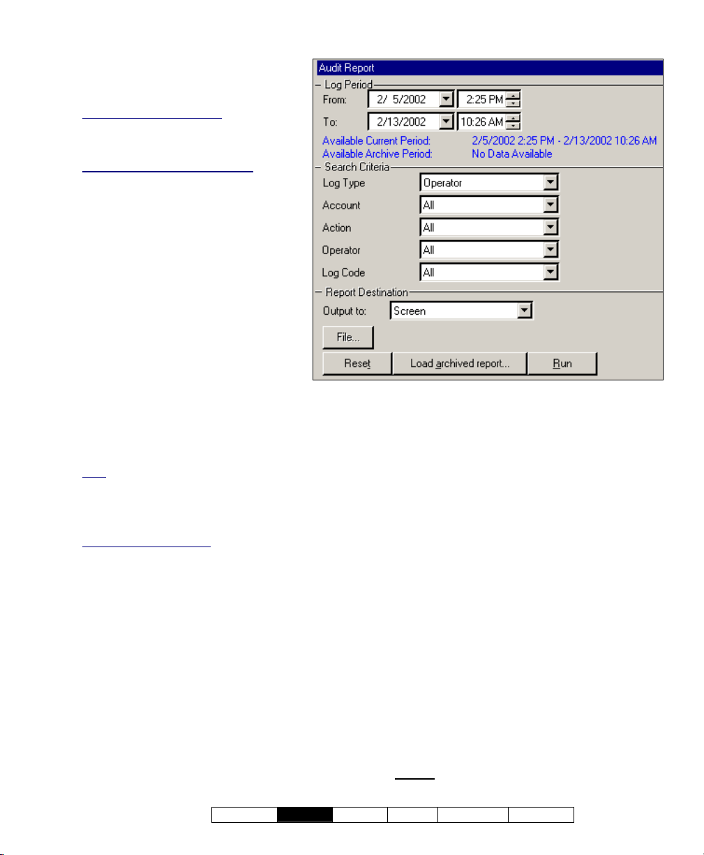
- Account: Select a specific account,
or "All" accounts.
Reports ÖAudit Report
- Action: This changes depending on
the type of report:
For an Operator audit report: The type of
action that was performed (add, delete,
etc.). "All" is recommended here, unless
you're looking for something more specific.
For a Communications Log Report
type of communications session
(normal/sync , get from panel, or send to
panel).
: The
- Operator (operator audit report only):
Select a desired operator, or "All" for
audits by any operator.
- Topic (operator audit report only): This is
the type of information that was
changed. Select "All" for changes
made to any topic.
Report Options
- Show Transaction Date/Time (for
communication logs)
: The date and time
for each communications event will be
shown only if this is selected (9).
- Show Transaction Details
operator logs)
: Selecting this (9) will
(for
cause details for user and operator
(Multi-Account Systems: Account Selection 'Tree')
- The area (near the centre of the screen) is where you select the
account that your report pertains to. Tip: This option appears only if
you didn't already have an account 'open' in the tree.
audits to be included in the report.
Note: This data will be available for reporting only if
this feature is turned on under “[Management],
ÖReporting”.
Details: Detailed Operator and User Audit Trail
(≥V4.6)
Director-Server Language
text comes through the Director-server. To
temporarily set it to a specific language, right-click the
Director-Server keypad/folder icon near the right-hand
end of the Windows taskbar, and make your selection
under “Language”.
: Some of the detailed audit
Report Destination / Output To
- Screen: This has the report sent to the 'Report
Viewer' window for viewing and/or printing
desired pages;
- Printer: This allows selecting a printer and
page-range, etc., and printing the report (without
viewing it first);
- Text File: This has the report saved as a
'comma-delimited' text file for manipulation with
another program. Allows you to change the
location and/or filename if desired.
- Report Emulation Text File: This has the
report saved as a formatted text file for viewing,
printing, or editing with a text editor or word
processor. Allows you to change the location
and/or filename if desired.
- Archive: This has the report saved as a
viewable archived report for viewing or printing
at a later time. Allows you to change the
location and/or filename if desired.
(Remaining Buttons)
- [File...]: This allows changing the location and
file-name for a report being saved for future
viewing, printing, etc. Tip: Use a different
name each time to avoid overwriting previous
reports.
- [Reset]: This provides a quick way to reset the
search criteria (to "Operator" audit report, and
find "All" audits).
- [Load Archived Report]: This allows browsing
for, and opening a previously saved reportarchive
(not for use with text files). The report
will appear in the report-viewer window for
21-0381E v4.7.3
Welcome
Report Control Admin Sys Config Tech-Ref
31
Page 40

viewing and/or printing.
For details on viewing and printing displayed reports,
refer to "Working with the Report Viewer".
- [Run]: This runs the report based on your
selected criteria. Additional screens will appear
depending on your selections (such as the
printer selection form, report viewer, etc.).
Reporting on Panel
Diagnostics
Panel Diagnostic Reports
This type of report allow s v iewing and printing
diagnostics lo gs generated by the 'Remote
Diagnostics' feature under Control & Status.
Related: ÖControl & Status, ÖPanel Control & Status,
ÖSystem, Ö[Get System Status]
Checking System Status (Remote Diagnostics)
As well, pa nel diagnostic reports can be
viewed and/o r printed righ t aw ay, saved for
future referen ce, or ex ported for manipulation
with another program.
Running a Panel Diagnostic Report
1) Select Panel Diagnostic Report from your
MyTools bar, or
and select Panel Diagnostic.
2) Multi-Account Systems: Select the desired
account near the centre of the screen.
Tip: This option appears only if you didn't already
have an account 'open' in the tree.
3) Select the desired report from the list near the
middle of the screen.
Tip: See the item-descriptions if you need help.
4) Select a report 'destination' (i.e., whether it is
to be viewed, printed, or saved as a file).
If you select "Archive" or a type of "File", click
[File...], set the location and filename as
desired, and click Save.
5) Click [Run], and respond to any additional
screen(s) that appear (details to follow).
For details on viewing and printing displayed reports,
refer to "Working with the Report Viewer".
(≥V4.4)
click [Reports] in the 'tree',
If Printing an Activity Report
To print a report without viewing it first: Select
the type of report and other criteria as usual,
and select Printer as the destination. Then,
select Run, and click OK w hen the 'Print'
screen appea rs. Tip: To select a dif ferent
printer click Printer, and make your se lection
from the 'Print Setup' screen that appears.
To view a report before prin ting
: Select the
type of report and other criteria as usua l,
and select ' Screen' as t he destination.
Then, click Run.
For details on view ing and print ing
displayed reports, refer to " Working w ith
the Report Viewer".
If Exporting an Activity Report as a File (Archive/Text File/Report Emulation File)
Select the typ e of report an d other criteri a as
usual, and the desired file-type a s the
'destination'. Then, click [File...]. In the next
screen, set the location and filena me as
desired, and click Save w hen finis hed.
Then click Run.
Viewing/Printing a Previously Saved Activity Report-Archive
Select Activity Report from your MyTools bar,
click [Repor ts] in the 'tree', and select
or
Activity. The n, click [Load ar chived r eport]
at the botto m of the form (scroll dow n if
necessary).
Multi-Account Systems: You do not have to select an
account since that was done when the report was
archived.
In the ne xt screen, locat e and sele ct the
desired archived report ( .raf), and click Open
(or simply double-click the file).
For details on viewing and printing displayed reports,
refer to "Working with the Report Viewer".
32 VEREX Director V4.73 User's Guide 21-0381E v4.7.3
Page 41
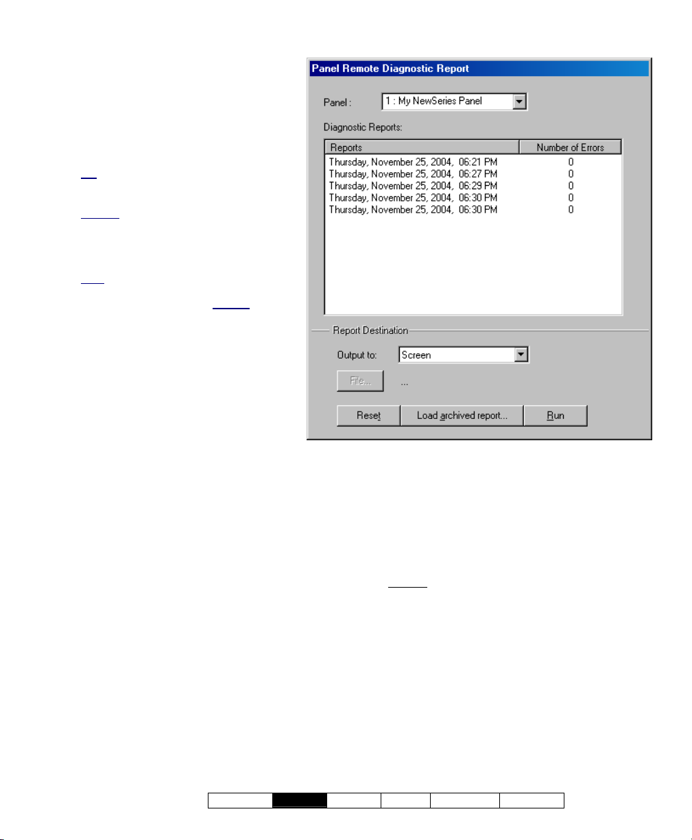
Reports ÖPanel Diagnostic
(Top of the Form)
- Panel: Select the panel you are
interested in here.
- Diagnostic Reports: The middle of
the screen shows a list of diagnostics
logs/reports that you can select from.
Tip: These logs are generated by the
'Remote Diagnostics' feature under Control
& Status.
Related
: ÖControl & Status, ÖPanel
Control & Status, ÖSystem, Ö[Get System
Status]
Checking System Status (Remote
Diagnostics)
Note
: The Director software retains 24
months worth of diagnostics sessions, or
the last 100—whichever is greater
.
Report Destination / Output To
- Screen: This has the report sent to the
'Report Viewer' window for viewing
and/or printing desired pages;
- Printer: This allows selecting a printer
and page-range, etc., and printing the
report (without viewing it first);
- Text File: This has the report saved
as a 'comma-delimited' text file for
manipulation with another program.
Allows you to change the location
and/or filename if desired.
(Multi-Account Systems: Account Selection 'Tree')
- The area (near the centre of the screen) is where you select the
account that your report pertains to. Tip: This option appears only if
you didn't already have an account 'open' in the tree.
- Report Emulation Text File: This has
the report saved as a formatted text
file for viewing, printing, or editing with a text
editor or word processor. Allows you to change
the location and/or filename if desired.
- Archive: This has the report saved as a
viewable archived report for viewing or printing
at a later time. Allows you to change the
location and/or filename if desired.
(Remaining Buttons)
- [File...]: This allows changing the location and
file-name for a report being saved for future
viewing, printing, etc. Tip: Use a different
name each time to avoid overwriting previous
reports.
- [Reset]: This provides a quick way to reset/clear
selections on the form.
- [Load Archived Report]: This allows browsing
for, and opening a previously saved reportarchive
(not for use with text files). The report
will appear in the report-viewer window for
viewing and/or printing.
For details on viewing and printing displayed reports,
refer to "Working with the Report Viewer".
- [Run]: This runs the report based on your
selected criteria. Additional screens will appear
depending on your selections (such as the
printer selection form, report viewer, etc.).
21-0381E v4.7.3
Welcome
Report Control Admin Sys Config Tech-Ref
33
Page 42
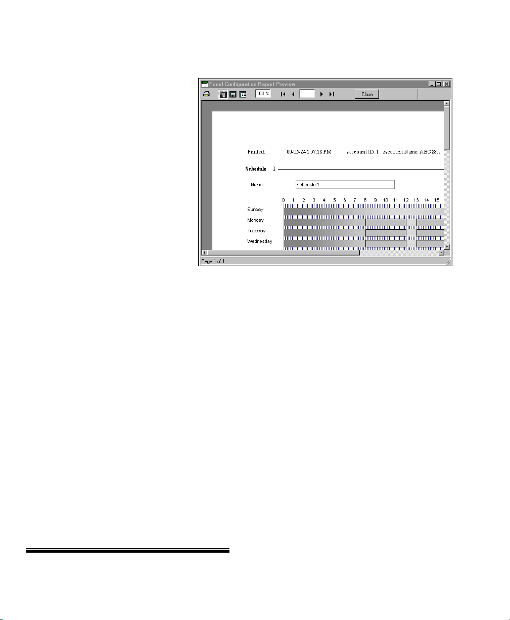
Working with the Report Viewer
The Report Viewer
When a report is set to be viewed, it
When Viewing a Report
appears with a toolbar allowing:
• Viewing different pages of the report;
• Setting the portion of each page that
will be visible at one time (zooming in
or out);
• Selecting a printer, and/or setting the
pages to be printed;
• Printing the report.
Setting the Size / Visible Portion of a Report
To change th e size/vis ible portion of
a report:
• Select one of the pre-set magnifi-
cation levels (page symbols), or;
• Enter a desired magnification in the
"%" box, and press Enter.
Viewing Different Pages
To view a different page:
• Use the 'browse' buttons to find a page
(typical), or;
• Enter a desired page-number into the
'current page' box.
Printing a Report
To print the report that is p resently on-screen,
click the print button (print er symbol). When
the nex t scre en appears, select your desired
page-range, etc., and click OK. Tip: To select
a different printer click Printer, and make your
selection from the 'Print Setup' screen that
appears.
VEREX Director automatically sets the preferred page
orientation for each report (portrait or landscape). This
setting should be left as-is.
Closing a Displayed Report and Returning to the Main Screen
To close the report view er window, and return
to the main desktop, click [Close] on the
report-viewer toolbar, or click the 'X' in the topright corner of the report viewer window.
(Report Viewer Toolbar)
- Print (printer symbol): This allows selecting
and/or setting up a printer, and printing either
the whole report, or a specific range of pages.
- Pre-set Magnifications (page symbols):
These selections allow viewing an entire page at
a time, or the page width, or viewing each page
actual-size (100% magnification);
- Zoom (xx%): This area shows the present
magnification level for the displayed report, and
allows entering a different value.
- |< < > >| (browse buttons): These buttons
allow moving to the first, previous, next, or last
page respectively.
- Current Page (xx): This area shows the page
number that is presently displayed, and allows
jumping to a different page by entering the page
number directly.
- [Close]: This closes the report viewer, returning
you to the VEREX Director desktop. (This is the
same as clicking the X in the top-right corner of
the screen.)
34 VEREX Director V4.73 User's Guide 21-0381E v4.7.3
Page 43

Monitoring System Activity
Alarm and Activity Monitoring
Alarm and Activity Monitoring through the VEREX Director System
When the VEREX Dire ctor system is
connected with specific p anel(s), all events
and alarms a re transmitted for display in the
monitoring window, allo wing the trackin g of
guard tours, and to allow f or various types of
report generation.
Dial up panels with dedicated external modems (one
panel per modem) can be set to automatically dial-in to
the VEREX Director system to transmit alarms or
blocks of activity messages. In other configurations,
the alarms and events are transmitted when a
connection is made with the specific panel(s)—either
manually, or at scheduled times.
Real-time monitoring (immediate reporting) through
VEREX Director requires that the software remain
connected with the specific panel(s).
Multi-Account Systems
activated for a specific account when you double-click
the account (under [Account Folders] in the tree).
For details on activating a panel connection, and the
"Stay Connected" setting, refer to "Panel
Communications and Updates".
To set a dial-up panel to automatically transfer alarms
or blocks of activity messages, refer to the configuration
topic: "Monitoring, Paging, & Remote Mgt. Settings".
: The monitoring window is
Sites Monitored through a CentralMonitoring Station
Sites can add itionally be m onitored through a
dedicated ce ntral-monitoring facility. In this
case, you can set whether only the 'alar ms' or
all activity is to be transmitted—on an are a-byarea basis. As well, individual sensors (input
points) and monitored panel conditions
(equipment / pseudo-points) can be set as to
the area arming states for w hich each
condition will be reported to the central-station
(On, Stay, and/or Off).
Monitoring Station Connection: Central monitoring is
supported through:
• The panel's built-in dialler ('Bell 103', 300 baud
modem), and/or;
• An "IP" connection (LAN/WAN--if ≥ v3.3 panel &
software), or;
• A high-security Mark 7 / DVACS connection (Canada).
The System Monitoring Window
The monitoring w indow shows the alarms and
activity messa ges for the a ccount select ed in
the tree (double-click an account to select).
Tip: Alarms typically appear with a red box next to
them (click the red box to open a "Notes" window).
Events with a camera symbol on the left are “Video
Events”. (Details to follow/below.)
Time Format
indicated in 12 hour or 24 hour format as per the time
format on each specific PC. This is set through the
Windows Control Panel under:
Regional and Language Options
(ÖRegional Options), Ö[Customize], ÖTime.
The top of the monitoring w indow shows either
the newest messages, or all 'unresolved' (and
higher priorit y) events first. As w ell, the
window can be set to show all activity, or only
specific types of events (saved per operator).
For details, refer to "Limiting the Window to Show Only
Specific Messages", to follow/below).
Tip: You can customize how alarms and events will be
displayed, and assign a sound to specific events if
desired. For details, refer to the configuration topic:
"Customizing How Events are Displayed"
The scroll-bar on the rig ht allo ws vie wing
events that have been pushed off the b ottom
of the screen.
Note: The 'heartbeat' icon in the bottom-right corner of
the screen will change to a red 8 until you select
[Return to Real-Time Mode]. (While scrolling, new
messages will not appear in the window.)
Messages are transmitted the VEREX Director
software:
• When you connect with an associated panel
(such as when updating a panel with
changes, or to check the status of a device);
• When a (dial-up) panel calls in to transmit
messages.
The Archive and Purge features allow keeping the
activity log to a more manageable size.
See: "Exporting or Importing Activity or Audit Logs",
and "Removing old Activity or Audit Logs".
: Beginning with Director v4.5, the time is
21-0381E v4.7.3
Welcome
Report Control Admin Sys Config Tech-Ref
35
Page 44

Split Screen Mode (Show Alarm Window)
For operators set to "Sho w Alarm Win dow",
unacknowledged alarms
w ill appear in a
separate window at the top.
Related: [Management], ÖOperator, Operator
Operators (People who can use this Software)
Notes
: • The "unacknowledged alarm" window will be
unavailable (greyed-out) whenever you choose to
[Browse Offline]; • Any selections you make under
[Filter] will apply to both parts of the window (details to
follow/below); • Details on acknowledging alarms
follows/below.
The Status Bar (bottom of the form)
The status area at the ex treme bottom o f the
screen sho ws w hether or n ot the soft ware is
presently connected with a specific p anel,
and/or if an update is presently in progress.
Activity messages are held at the specific panel
whenever it is being updated/synchronized with the
software (the messages will be available for
transmission after the update is finished).
Also See: (Topics Pertaining to Central Monitoring):
• "Primary Reporting" selections under "Monitoring,
Paging, & Remote Mgt. Settings".
• "Reporting" setting under "Areas and Related
Settings".
• "Inputs—Monitored Sensors", and the "Transmit"
selections under "Inputs—Pre-Defined Point Types",
"Inputs—Custom Point Types", and "Equipment
Settings (Pseudo/Internal Inputs)".
Connecting to the Associated Panel(s), An Overview:
For the latest up-to-date messages, you must
be connected w ith th e as sociated pan el(s).
(Otherwise, y ou w ill see only messages that
were received previously).
1) See if you're already connected by
checking the status bar at the bottom of
the monitoring window.
Multi-account systems: Ensure your
desired account is selected
(click [Account Folders] in the tree, and
then double-click the specific account).
2) If not connected, check to ensure the
communication software is running on
the specific PCs.
Detail: If the LCD/Telephone icon on the Windows
taskbar is black-and-white (colour = running), start
the communications service by right-clicking the
icon, and selecting "Start Communications".
Related Topic
(Communications Manager)
: Serial Port / Modem Setup
3) Selec t Communications from your
MyTools bar, or
click
[Communications] in the 'tree', and
select Pending/OnLine.
4) Click the [+] at the bottom of the form, or
right-click the form, and select Add New
from the pop-up menu. Then, select the
desired panel(s) (double-click to select),
and set "Action" to "Normal", and
"Frequency" to "Stay Connected" (9).
'Activating' and Using the Monitoring Window
Selecting an Account (Multi-Account Systems)
Click [Account Folder s] in the 'tree', and
locate and d ouble-click th e desired ac count.
The monitoring w indow w ill sho w the
messages for the account that have been
received.
Tip: Your selected account will remain 'open' (e.g., for
the event monitoring window) until you select [Account
Folders] or [Management] in the 'tree'. Selecting an
account is typically not required for a single-account
system (single account license and/or operators without
authority to edit account folders).
36 VEREX Director V4.73 User's Guide 21-0381E v4.7.3
(Click OK when finished.)
5) Check that the connection is made, and
watch for the panel updates to occur.
(Click the 'Panel Group', and look for the status on
the right side of the screen.)
Note: Alarm and activity messages are transferred
the panel updates (look for a connection state of
after
'Connected' and 'Idle State'.)
Also See (Related Topics):
+ "Panel Communications and Updates"
Opening and Adjusting the Monitoring Window
If the monitor ing window is not vis ible, click
[Events] on the toolbar.
If nothing seems to happen, click [Reset] on the toolbar
(and click [Events] again if necessary). Note: If your
desktop was accidentally saved with the monitoring
Page 45
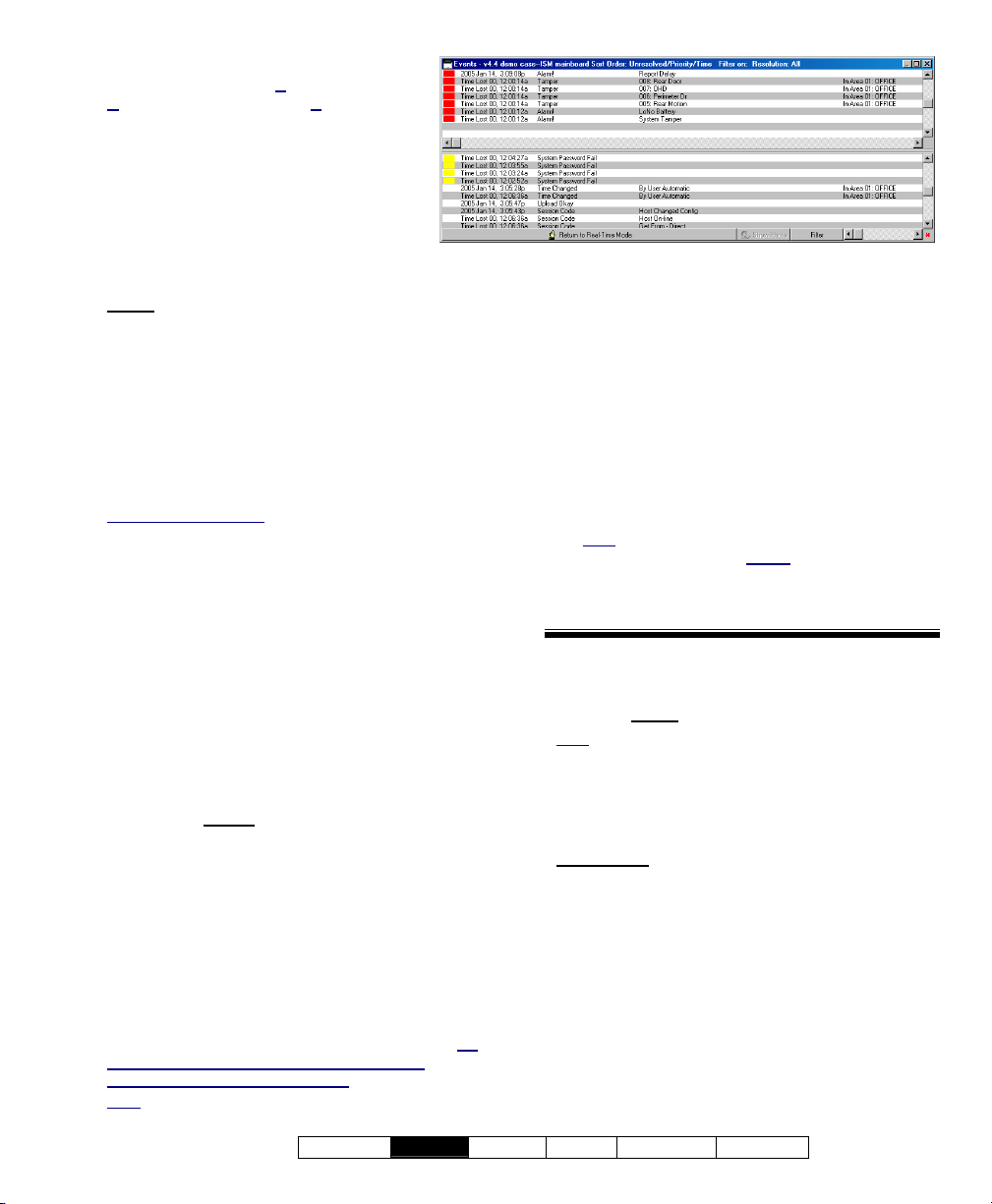
window 'undocked' and hidden behind the
main desktop, open the V
esktop Settings, and then Default.
D
iew menu, select
To adjust the size of the monitoring
window, position the mouse cursor at
the top of the w indow, watching for
the cursor to change shape. Then,
click-and-drag the top of th e windo w
to the desired new position.
To max imize the size of the
monitoring window, double -click its tit le-bar
.
twice
To restore the VEREX Director desktop at any time,
simply click Reset on the toolbar.
(If the monitoring window is presently maximized,
double-click its title-bar first.)
Tip: With multi-monitor support, you can place the
monitoring window in a separate screen: Double-click
the monitoring window title-bar, and then drag it onto
the second screen.
Reminders: The monitoring window is updated only
when you are connected with the specific panel(s).
Muti-Account Systems
active only while you have a specific account 'open' in
the tree (select [Account Folders], and then doubleclick the account).
Monitoring Window Blank During or After a Panel
Update: The monitoring window may take a minute or
two to refresh at the end of a panel communications
session (please be patient). As well, to ensure the
desired type of messages are shown, click [Filter], and
verify the filtering / sorting selections (details in a
following topic).
: The monitoring window is
Viewing Activity Messages
To vie w olde r messages in the monit oring
window, c lick [Browse Offline], and then use
the scroll-bar on the right (click the up or d own
arrows, or slow ly
drag the control bar in the
middle).
Click [Return to Real-Time Mode] to view the
newest event s as they occur. (These w ill
appear at the top of the monitoring window.)
For longer messages, use the horizontal scrollbar (bottom-right) to view the end or beginning
of the desired message(s).
If you wish to print activity messages, refer to
"Reporting on System & Personnel Activity.
When alarms occur, ensure they are not ignored. Be
sure to dispatch someone to deal with any
conditions that require attention.
: Sounds may be associated with alarm
Note
messages. (The default for alarms that require
resolution is your PC's "exclamation" sound--as set
through the Windows control-panel.)
To have unacknowledged alarms appe ar in
a separate window at the top for a spe cific
operator:
1) Ensure the specific operator is set for "Show
Alarm Window".
Related: [Management], ÖOperator, Operator
Operators (People who can use this Software)
2) Ensure the 'Sort Order' and 'Filtering' is set
as desired under [Filter].
(See "Limiting...", to follow/below);
Note: To return to a single 'pane' monitoring
window, ensure "Show Alarm
selected on the form for the specific operator.
Also see "Split Screen Mode (Show Alarm
Window)", previous/above.
Window" is NOT
- Vertical Scroll-Bar (right-hand side): Allows
scrolling up and down to view older messages in
the monitoring window. (Click the up or down
arrow, or slowly drag the control bar.)
Note: This puts you into "Offline Browsing" mode, and
stops new events from entering the window. (Same
as clicking [Browse Offline].)
- Horizontal Scroll-Bar (bottom-right): Allows
scrolling to the left and right to view longer
messages. (Click the left or right arrow, or drag
and release the control bar.)
- Status Bar (bottom of screen): Shows if the
software is connected with a specific panel, and
if an update is in progress.
- [Browse Offline] / [Return to Real-Time
Mode]: Allows activating the event monitoring
window vs. scrolling inside it.
- [Show Photo]: This allows manually opening
the photo-verification window to view the last 1,
4, or 9 entrants.
For more information, refer to "Visually Verifying Users
(Photo-Verification)".
21-0381E v4.7.3
Welcome
Report Control Admin Sys Config Tech-Ref
37
Page 46

- [Filter]: Allows resorting the event / monitoring
window, limiting the list to show specific types of
messages only, and/or only messages that have
not been 'resolved'
Limiting the Window to Show Only Specific
"
(see last 2 items below, plus
Messages".);
- (Activity Messages): Each message shows:
• A coloured bar for the message priority;
• The date and time the event occurred;
• The type of event/message;
• Details on the specific event.
• A reference number and the name of the
panel that sent the alarm;
"Session Code" messages pertain to panel
communications/update sessions being started or
completed. (For details on communications sessions
that have occurred, refer to "Panel Communications
and Updates".
"System Check" messages are for internal use, and/or
of interest only when working with your technical
support representative.
-------------------------
-
(coloured box): Alarms are shown with a
box/button on the left of the message (typically
red, but customizable). Clicking the button
allows entering a comment for the message
(and viewing previous comments), and/or setting
messages as being 'resolved';
9: The event has been set as 'Resolved' (dealt with).
(you'll see this only if displaying resolved events);
?: A comment has been entered, but the event was
not set as 'Resolved'.
Sounds
: Custom sounds can also be associated with
different types of alarms. The default sound for
alarms that require resolution is the PC's 'exclamation'
sound (as set through the Windows control panel).
Related Topic
Displayed
: Customizing How Events are
- Resolve All (Right-click, or from the Edit Menu):
Allows entering a comment for all displayed
alarm messages, and setting them all as being
'resolved'.
TechTip: Alarms and events can be set as 'resolvable'
or not (i.e., whether or not the comment/resolution
screen will be available). For details, refer to the
configuration topic: "Customizing How Events are
Displayed".
Limiting the Window to Show Only Specific Messages (Sorting and Filtering)
Operators wit h "Event Filte r" permission can
set the monitoring window to show:
• All event messages for an account;
• Only 'unresolved' events;
• Events of a specific priority range;
• Events pertaining to a specific door, area,
person, etc.
Tip: These selections are saved separately for each
operator.
Exception
assigned to operators--to determine the types of
messages each operator will be able to see during vs.
outside of set times.
Tip
bottom of the monitoring window indicates that
scheduled event filtering is presently in effect (for the
current operator).
Related Topic(s)
Operators
You can also set the 'sort-order' for messages.
To determine the present sort-order, and
whether or n ot the list is limited to s pecific
events, look f or references in the title-b ar of
the monitoring window.
To set the w indow to show only specific types
of messages, click [Filter] at the bottom, and
make your selections from the pop-up window.
Tip: You can select [Clear] to remove your present
'filters', and return to showing all messages for the
present account.
: Scheduled Event Filters can be set up and
: A clock symbol on the [ Filter ] button at the
: Scheduled Event Filtering for
38 VEREX Director V4.73 User's Guide 21-0381E v4.7.3
Page 47
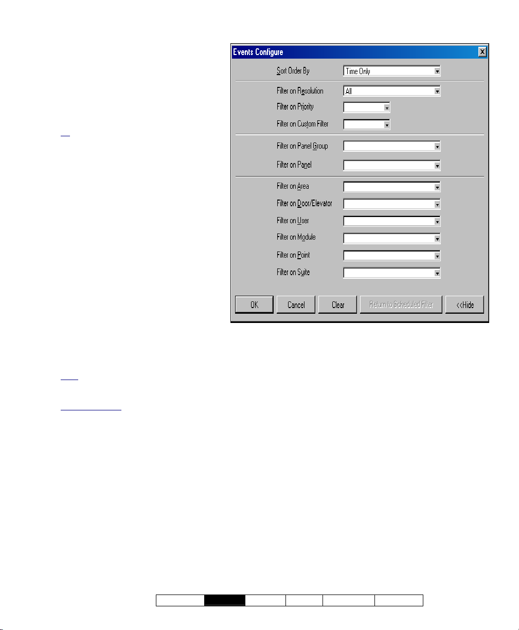
- Sort Order By: This allows listing
When you Click [Filter]
messages in order by date/time only,
or showing 'unresolved' (and higher
priority) events first.
- Filter on Resolution: This lets you
have the list include events depending
on whether or not they have been
'resolved' (i.e., dealt-with).
All: This shows all events--including ones
not associated with the comment/resolution
feature (i.e., not set as 'resolvable').
- Filter on Priority: This allows limiting
the window to show only events of a
desired priority value (or range).
- Filter on Custom Filter: This allows
limiting the window to show only
events of a desired 'custom-filter' value
(or range).
Also See: To assign priorities, 'Custom
Filter' values, and other parameters, refer to
the configuration topic: "Customizing How
Events are Displayed".
- [Clear]: Removes all filters--i.e.,
returns to the factory settings (and
closes the 'filter' window).
[Return to Scheduled Filter]: For
-
an operator who's selections have
temporarily overridden scheduled event filtering
(requires "Events Filter" permission), selecting
this will return to the scheduled settings.
Note: This button becomes available once the filtering
changes have been saved (e.g., exit, then return to
this screen).
Related Topic(s)
Operators; • Operator Permissions
: • Scheduled Event Filtering for
[More] / [Hide]
- Filter on Item: For events pertaining to a
specific person or door, etc., select the desired
item here.
21-0381E v4.7.3
Welcome
Report Control Admin Sys Config Tech-Ref
39
Page 48
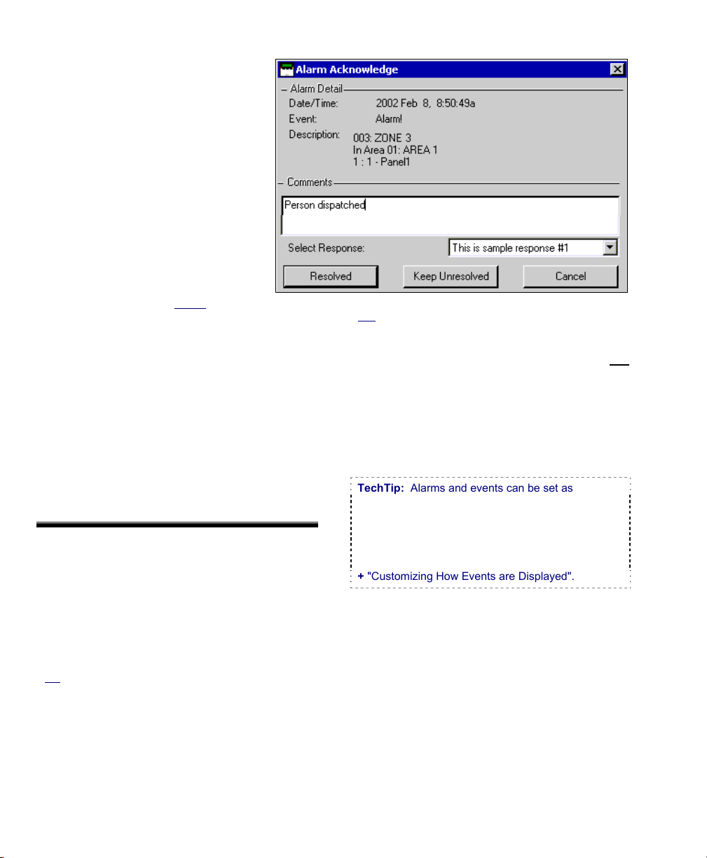
(Click the Coloured Box for an Alarm Message)
Acknowledging Alarms (Comment / Resolve)
Alarm Notes / Comments
While responding to alarms, you can
enter a note for each alarm
describing what caused it, w hat was
done to correct the problem, etc. You
can also set t he alarm as 'resolved' (
9 ), or 'Keep Unresolved' ( ? ).
Tips: Whether 'Resolved' or not, alarms will
be considered to be 'Acknowledged'--unless
you click [Cancel]. You can set the
monitoring window to show only alarms that
either have, or have not been 'resolved' (for
details, refer to the preceding topic).
For operators set to "Show Alarm
unacknowledged alarms will appear in a separate
window at the top.
Related: [Management], ÖOperator, Operator
Operators (People who can use this Software)
Entering or Viewing Alarm Comments
To enter (or view) an ack nowledgement note
for an alarm, click the re d area besid e the
alarm.
Then, enter the desired message and s elect
[Resolved], or [Keep Unresolved].
You can enter two or three short notes (saved
individually by clicking OK) or a single larger one for
each alarm as desired.
- Alarm Detail: Details on the alarm, and when it
occurred.
- Comments: Previously entered comments, plus
an area to enter new one(s). Tip: There is
enough space for two or three short notes
(saved individually by clicking OK), or a single
larger note.
Tip: You can type your response, or select a
previously-defined one to use as a starting point under
"Select Response" (to follow).
- Select Response: This allows selecting a
previously-defined response (open the 'drop-list'
and make your selection). These responses
can be used as-is, or edited as desired.
Note: To be available here, sample responses must
be defined first:
Window",
Ref
: Account Information ÖEvent Response
Event Responses for Acknowledging Alarms
- [Resolved]: Sets the event as having been
dealt-with. If the alarm/monitoring window is not
set to show only unresolved alarms, you'll see
the message with a "9" beside it.
- [Keep Unresolved]: This saves your comment,
and displays the event with a "?" beside it to
indicate further resolution is needed.
- [Cancel]: This aborts any changes you entered
in the 'Alarm Acknowledge' screen.
TechTip: Alarms and events can be set as
'resolvable' or not (i.e., whether or not the
comment/resolution screen w ill be available). As
well, if 'instructions' have been s et up for the specific
type of alarm, they will appear here. For details, refer
to the configuration topics:
+ "Alarm/Event Instructions", and
+ "Customizing How Events are Displayed".
40 VEREX Director V4.73 User's Guide 21-0381E v4.7.3
Page 49

When Messages Cannot be Transmitted to the VEREX Director Software
If the VEREX Director softw are is not
connected with the specific panel, messages
are not transmitted, and each individual p anel
will retain up to 65,536 of the latest ev ents
that occurred.
Exception: Remote (dial-up) panels with their own
dedicated
can be set to automatically 'dial-in' and transmit
messages to the Director software. These messages
will appear in the monitoring window when you access
the associated account.)
For details, refer to "Monitoring, Paging, & Remote
Mgt. Settings".
Note: Panel connections require that the
communications software be running on the specific
PC. The event-log capacity of each panel depends on
the panel's "Feature Set" selection. For details, refer
to "Account-Wide Panel Settings".
external modem (i.e. one panel per modem)
21-0381E v4.7.3
Welcome
Report Control Admin Sys Config Tech-Ref
41
Page 50

Working with Video Events (≥V4.5)
About Video Events)
Video events are specific e vents pertaining to
input points and doors that have been
associated with recordings from one or t wo
specific cam era(s). The se appear with a
camera symbol on the left in the event
monitoring window.
DVR Types: Supported video servers include:
NetVision (V2.1 or V2.2 and newer)
Yes (via "Visual Director")
March R4 & R5
Optional via licensing (beginning with V4.7).
VeDVR / NVe (embedded)
Optional via licensing (beginning with V4.71).
Note: Playback for video events is NOT supported for
March R4 DVRs.
Related: "Setting up Video Events".
Also See:
+ Maps and Video (Visual Monitoring & Status/Control)
+ Camera Status/Control and Adjustments
Opening a Video Event
Open your d esired accoun t in the ‘tree’, and
ensure the event mo nitoring w indow is
displayed. To vie w the as sociated recor ding,
click the cam era symbol for the specific event.
If a video th at coincides with the eve nt is
available, it will open and start playing
automatically starting at the time of the
triggering event.
If an image does not appear, this typically means that
either a recording is not available from the specific
camera for this time-slot, or the Director software is
unable to communicate with the NetVision Video Server.
Then, refer to the item-descriptions fo r this
screen for details on your available choices.
42 VEREX Director V4.73 User's Guide 21-0381E v4.7.3
Page 51
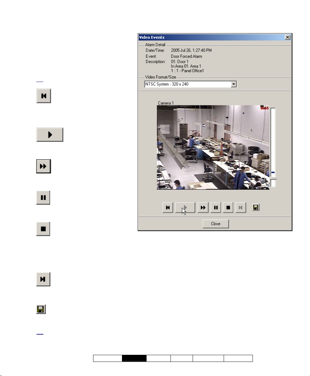
- Vertical Slider bar on the right: This
indicates your relative position within
the recorded video during playback.
For recordings associated with a video
event, a dark band will show when the
triggering event occurred within the
recording.
Tip: This is used as the default starting
location for playback.
- (Play Previous Clip): Plays
the video recording saved immediately
prior to the present one (at the
NetVision PC
).
(Click the Camera Symbol for a Video-Event Alarm
Message)
-
(Play): Starts or
continues playing the present (I.e.,
displayed) video clip.
-
(Fast-Forward Play): Causes
the present video to play at doublespeed.
- (Pause): Stops a playing video,
while remembering your present
location in the video.
- (Stop): Stops playing the
present video and disregards your
present location. (Clicking play will restart the
video at the time of the triggering event (if
applicable), or otherwise at the beginning of the
file.
(Play Next Clip): Plays the video
-
recording saved immediately after the present
one (at the NetVision PC
).
- (Save As): Allows downloading and saving
the displayed video-clip to any location that is
accessible through your PC.
Tip: If this action fails, check to ensure that all
requirements are being met, and everything is set up
correctly. (You may also need to enlist the help of
your network administrator.)
Related: "Setting up Video Events".
- [ Close ] : Closes the video viewer.
21-0381E v4.7.3
Welcome
Report Control Admin Sys Config Tech-Ref
43
Page 52
Visually Verifying Users (Photo-Verification)
Photo-Verification
Introduction
Each operator can select d oor(s) to have the
stored photo for entrants displayed each time
someone gain s access (or is denied entr y) at
any of the selected door(s). The last 1, 4 , or 9
entrant's photos can be displayed.
The photo ca n then be us ed to verify each
entrant's identity. This can be done locally-such as by an attendant in a reception area, or
remotely through a camera on a map.
This feature is configurable separatel y for each
operator (as described in a following section/below).
This pertains to the photo associ ated with
each card/person in the " Users" sc reen.
For detail s, see "The Photo-Bad ging
Option".
Connecting to the Associated Panel(s), An Overview:
This feature w orks only w hile you are
communicating w ith the specific panel(s). To
establish a connection:
1) See if you're already connected by
checking the status bar at the bottom of
the monitoring window.
Multi-account systems: Ensure your desired
account is selected (click [Account Folders] in the
tree, and then double-click the specific account).
2) If not connected, check to ensure the
communication software is running on
the specific PCs.
Detail: If the LCD/Telephone icon on the Windows
taskbar is black-and-white (colour = running), start
the communications service by right-clicking the
icon, and selecting "Start Communications".
Related Topic
(Communications Manager)
: Serial Port / Modem Setup
3) Selec t Communications from your
MyTools bar, or
click [Communications]
in the 'tree', and select Pending/OnLine.
4) Click the [+] at the bottom of the form, or
right-click the form, and select Add New
from the pop-up menu. Then, select the
desired panel(s) (double-click to select),
and set "Action" to "Normal", and
"Frequency" to "Stay Connected" (9).
(Click OK when finished.)
5) Check that the connection is made, and
watch for the panel updates to occur.
(Click the 'Panel Group', and look for the status on
the right side of the screen.)
Note: The photo-verification feature will be available
after
the panel updates finish (look for a connection
state of 'Connected' and 'Idle State'.)
Also See (Related Topics):
+ "Panel Communications and Updates"
44 VEREX Director V4.73 User's Guide 21-0381E v4.7.3
Page 53
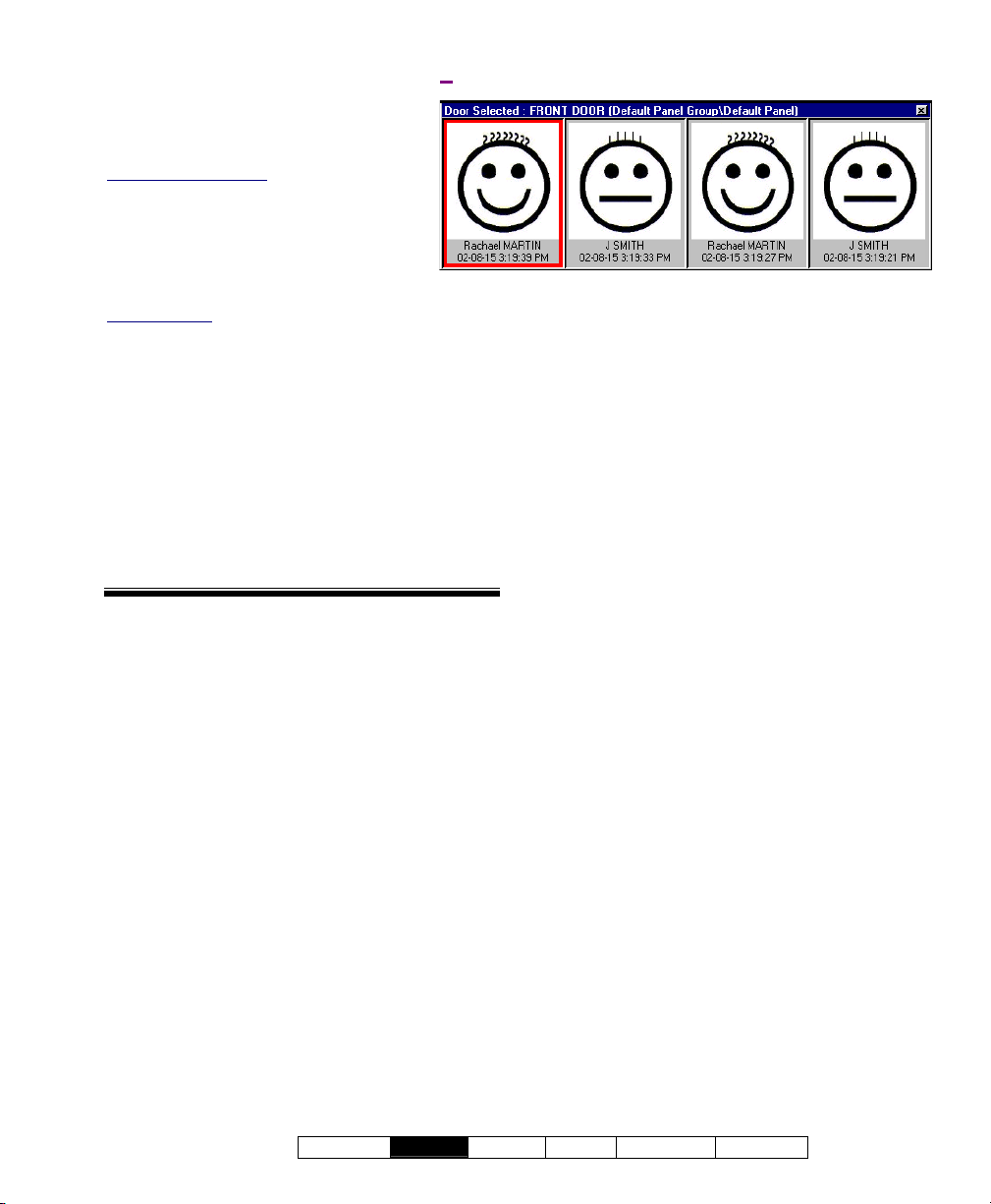
Using This Feature
View (menu) ÖPhoto Verification ÖShow
(or when a person enters at the specific door)
The photo w indow opens
automatically w henever a person
gains access at the specific door.
Multi-Account Systems: This works only
while the specific account is selected. (Click
[Account Folders] in the 'tree', and doubleclick the specific account.)
You can also open the photo w indow
manually by clicking [Show Photo] at
the bottom of the monitoring window.
Window Empty: The photo window is cleared each
time settings are changed for this feature, and when
you select anything outside of the specific account.
Now, visually compare the displayed photo
with the person to verify their identity.
Setting the Window Position
To reposition the photo w indow, s imply c lickand-drag its title-bar to the new location.
Closing the Photo Window
To close the photo window at any time, click
the [X] in the upper-right corner.
This screen shows the last 1, 4, or 9 persons
who gained entry (or were denied access) at a
door that you selected for photo-verification.
The photo window is cleared each time you change
settings for this feature, and when you select anything
outside of the specific account.
--------------------------------------------------------------------------
Related Features
Additional features can be u sed in conjunction
with photo-verification (all optional):
• Event-T riggered camera-viewing
See: "Initial Set Up of: Views, Maps, Cameras"
(especially step 3b)
• Card-enrolment (or disabling) readers--that are
also set to unlock.
a Door" (look for [Card Action] ).
• "Command Point" custom input points (e.g.,
to unlock the door, or "Grant Last User").
See: "Input Points—Custom Point Types", and
"Input Points—Monitored Sensors"
• "Grant Last User" command
door on a map)
See: In the section on using maps and cameras,
see: "Controlling an Area or Device" (look for
"Door Commands", then "Grant Last User...").
See: "Reader 1 & 2 Settings for
(right-click the
21-0381E v4.7.3
Welcome
Report Control Admin Sys Config Tech-Ref
45
Page 54
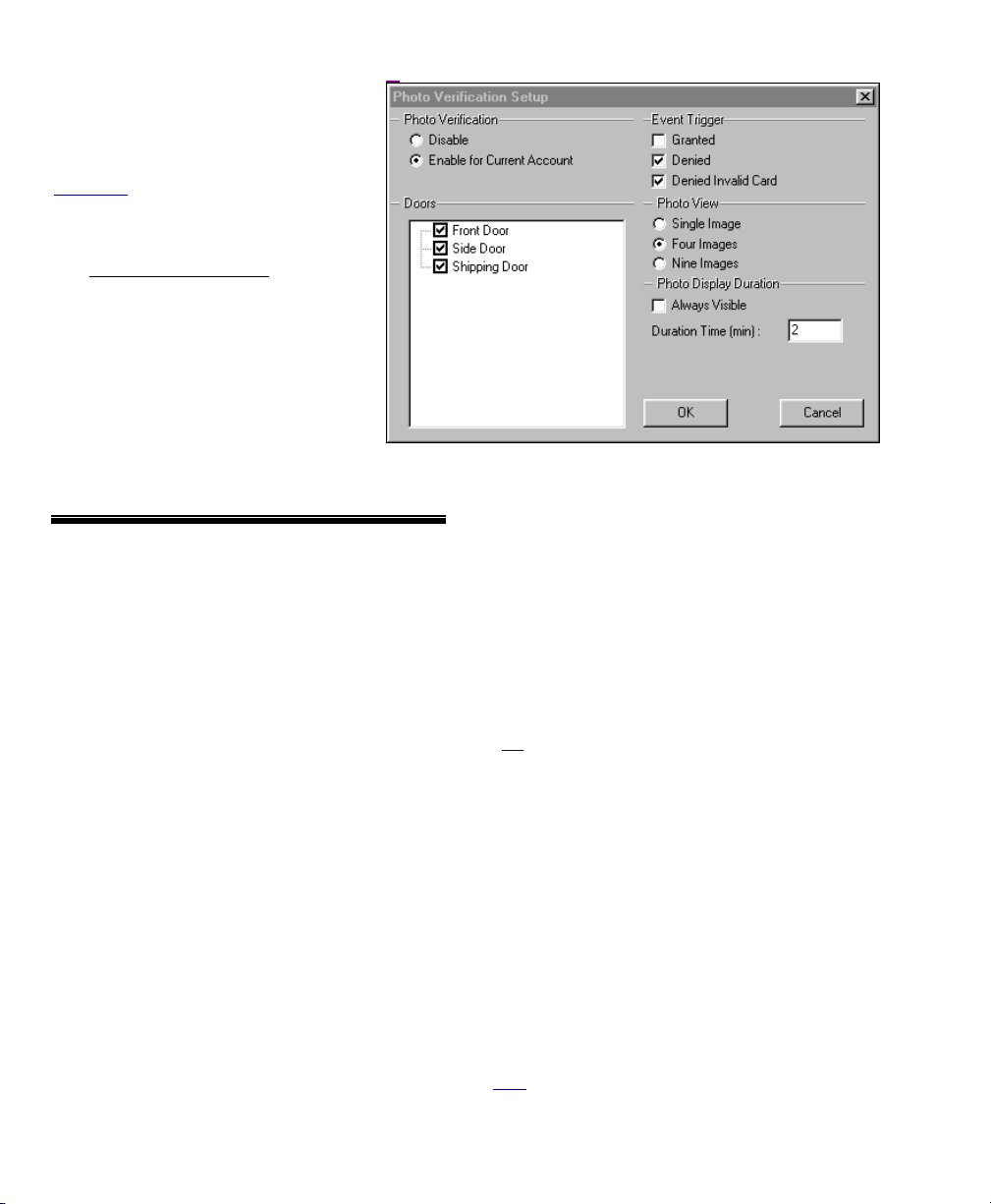
View (menu) ÖPhoto Verification ÖCustomize
Setting up This Feature
Each operato r can set the photoverification f eature to suit their
preferences.
Authorities: This feature is available to all
operators.
Steps:
1) Multi-Account Systems: Ensure
you are 'in' the desired account.
(Click [Account Folders] in the
'tree', and double-click the specific
account.)
2) From the View
ÖPhoto Verification
ÖCustomize.
3) Refer to the selection-descriptions
for this screen while making your
selections.
Photo Verification
- Disable: Photo verification will be turned off
while you are logged in (i.e., the present
operator);
- Enable for Current Account: Select this to
have photo-verification turned on while you are
logged in (i.e., the present operator);
-------------------------
Event Trigger
This allows setting the type of card-activity that will
trigger the photo for each user at the selected door.
You can select any or all of these items.
- Granted: Persons that are granted access;
- Denied: Valid/programmed cards that are
denied access for general reasons (card
expired, wrong time, wrong area, etc.);
- Denied Invalid Card: Persons denied access
due to: • Wrong system code; • Wrong PIN
entered; • Antipassback violation; • Wrong
card version number; • Dual custody violation.
menu, select
Doors
This area shows all main panels and doors
associated with your account, and allows
selecting the door(s) to be associated with
photo-verification. (Click to select or de-select
doors in the list.)
Tip: You can change the way doors are displayed by
right-clicking this area, and selecting from the pop-up
menu (try it!). Note: To exit from "Physical view" (9),
just select it again.
-------------------------
Photo View
This allows selecting the number of user photos
that will be visible at one time (1, 4, or 9);
Photo Display Duration
- Always Visible: The photo-verification window
will remain open for as long as you remain 'in'
the specific account;
- Duration Time (min): If you do not select
"Always Visible", this allows selecting how long
the photo window will remain open each time it
is activated (1-99 minutes).
Note: You can also close the photo window manually,
by clicking the [X] in the upper-right corner.
46 VEREX Director V4.73 User's Guide 21-0381E v4.7.3
Page 55

Guard-Tours: Monitoring
Introduction to Guard Tours
Guard Tours
A guard-tour can be thought of as either:
• A path that must be completed by a guard in
a certain amount of time—including stations
(checkpoints) along the way, or;
• The process of the guard making his/her way
through the assigned route.
Tip: If so configured, areas can be disarmed and rearmed automatically as the guard moves through the
designated route.
Note: A guard tour cycles through the defined 'stations'
(checkpoints) and then stops (it does not automatically
restart at the beginning).
Each 'station' can be a reader/door (that will be
monitored for a specific u ser), or a physical
input-point (key-switch, etc .) that is operated
by the guard.
Once defined guard tours can be activated
and/or monitored by anyone with the
appropriate permissions. As well, reports can
be generated on guard to urs that occurred
previously.
Guard Tour Monitoring
When any gu ards are to begin their assigned
routes, the associated "Gua rd Tours" can be
activated, thus allowing an operator to monitor
each guard's progress, and respond if needed.
Guard Tour Events: Activity messages pertaining to
guard-tours (and guard-tour stations) are not
transmitted to a central monitoring facility.
Guard Tour Setup
monitored, it must first be defined as per the stations
(checkpoints) along the way, and the allowable times
between stations. (Details appear in a following section
/ below.)
: Before a guard-tour can be
Connecting to the Associated Panel(s), An Overview:
1) See if you're already connected by
checking the status bar at the bottom
of the monitoring window.
Multi-account systems: Ensure your desired
account is selected (click [Account Folders]
in the tree, and then double-click the specific
account).
2) If not connected, check to ensure the
communication software is running
on the specific PCs.
Detail: If the LCD/Telephone icon on the Windows
taskbar is black-and-white (colour = running), start
the communications service by right-clicking the
icon, and selecting "Start Communications".
Related Topic
(Communications Manager)
: Serial Port / Modem Setup
3) Selec t Communications from your
MyTools bar, or
click
[Communications] in the 'tree', and
select Pending/OnLine.
4) Click the [+] at the bottom of the
form, or right-click the form, and
select Add New from the pop-up
menu. Then, select the desired
panel(s) (double-click to select), and
set "Action" to "Normal", and
"Frequency" to "Stay Connected" (9).
(Click OK when finished.)
5) Check that the connection is made, and
watch for the panel updates to occur.
(Click the 'Panel Group', and look for the status on
the right side of the screen.)
Note: Guard-tour monitoring features will be available
the panel updates have finished (look for a
after
connection state of 'Connected' and 'Idle State'.)
Also See (Related Topics):
+ "Panel Communications and Updates"
21-0381E v4.7.3
Welcome
Report Control Admin Sys Config Tech-Ref
47
Page 56

Activating and Monitoring Guard Tours (that have already been set up)
Activating a Guard Tour (Adding it to the Guard Tour Monitor)
Initiate a connection with the asso ciated
panel(s) as described previously / above.
Then, select Guard Tour Monitor from the
MyTools bar, or
in the tree, 'open' Control & S tatus (click the
"+"), and select Guard Tour Monitor.
Multi-Account Systems: First select [Account Folders]
in the 'tree', and double-click the desired account.
Now, use the Grid / Form toolbar-button to
select your preferred view-mode.
Forms view: Status for one guard-tour at a time;
Grid View
: All active tours in a list.
In 'Forms' view, right-click the form, and select
Start Tour (or Add Ne w). (For 'Grid' view,
click the [...] beside the word "Start".)
Then, refer to the selection-descriptions for this
screen while selecting a "Guard Tour", "Start
Point", and "User". (Click OK when finished.)
Monitoring Guard Tours in Progress
Select Guard Tour Monitor from the MyTools
bar, or
click your site/acco unt button in the
tree, 'open' Control & S tatus (click the "+"),
and select Guard Tour Monitor.
Multi-Account Systems: First select [Account Folders]
in the 'tree', and double-click the desired account.
Then, use the Grid / Form toolbar-button to
select your preferred view-mode.
In forms view, you can select a 'tour' at the
bottom of the w indow, or right-click the form
and select Find to search for a guard -tour by
name (or the 1st few characters--e.g., nam∗
Refer to the selection-descriptions for this
screen w hile monitoring t he specific guard
Be sure to dispatch someone promptly if the
tour.
need arises
click your site/account button
).
.
Tip: To view additional items, you can use the scrollbar at the bottom of the window.
Note: Guard tour monitoring will be suspended if the
panel connection is dropped for any reason. (You can
check your connection status simply by checking the
status bar at the extreme bottom of the desktop.)
Stopping the Monitoring of a Guard Tour (Deleting it from the Guard Tour Monitor)
Select Guard Tour Monitor from the MyTools
bar, or
click your site/acco unt button in the
tree, 'open' Control & S tatus (click the "+"),
and select Guard Tour Monitor.
Multi-Account Systems: First select [Account Folders]
in the 'tree', and double-click the desired account.
Then, use the Grid / Form toolbar-button to
select your preferred view-mode.
In forms view, you can select a 'tour' at the
bottom of the w indow, or right-click the form
and select Find to search for a guard -tour by
name (or the 1st few characters--e.g., nam∗
).
Then, right-click the form and select End Tour
(or Delete). When asked to confirm, select
Yes.
(In Grid vie w, click the ( Stop) [...] on the row
for the desire d tour. When asked to confirm,
select Yes.)
48 VEREX Director V4.73 User's Guide 21-0381E v4.7.3
Page 57
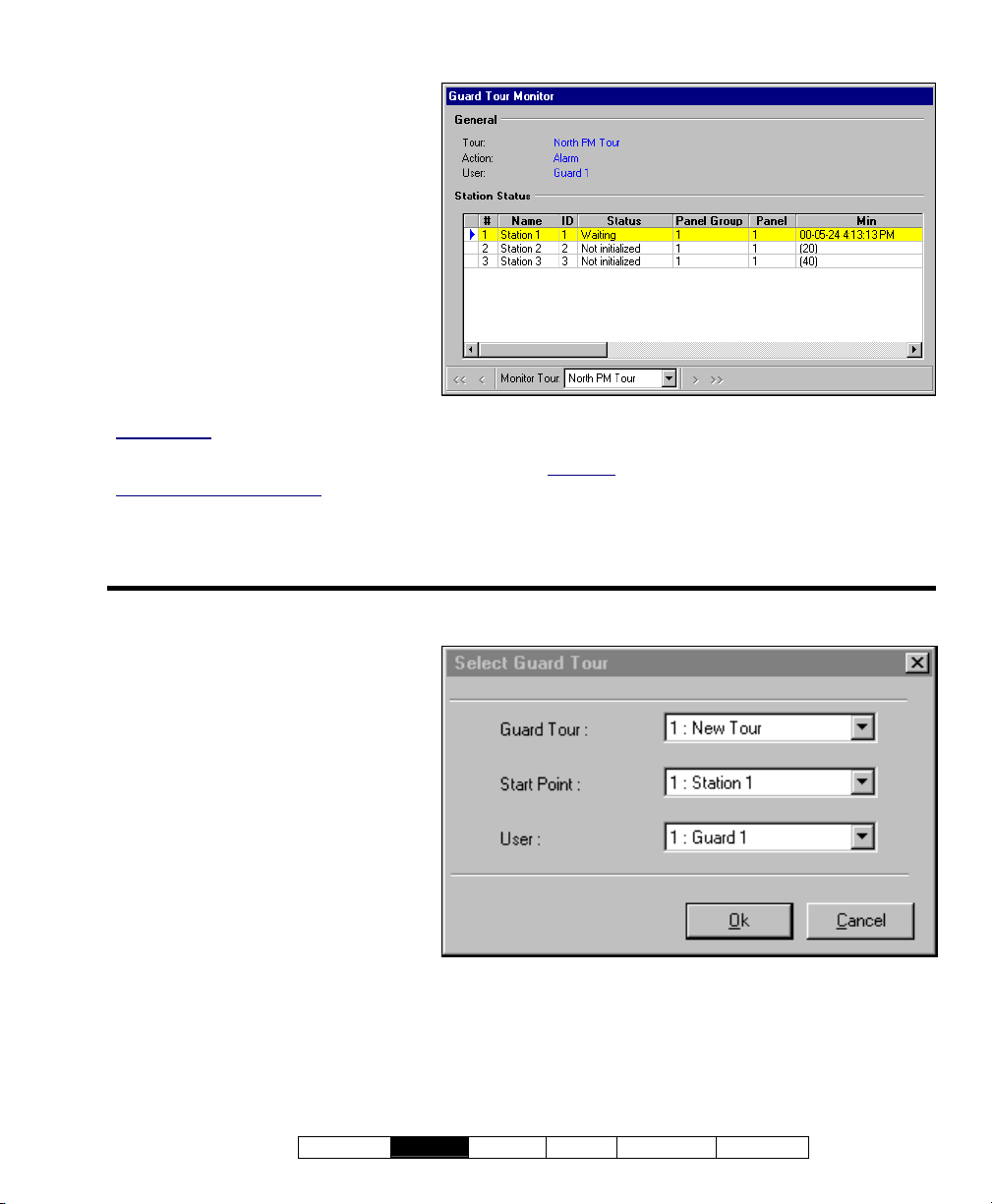
Control & Status ÖGuard Tour Monitor
- Monitor Tour (bottom of form): This is
where you select an active guard tour
to view its progress/status. This area
shows the name of the guard tour (as
defined under "Guard Tour");
- General: This area shows the 'tour'
being monitored, plus the name of the
guard (user), and the defined action to
occur if the guard is late or absent at
any of the stations (checkpoints).
- Station Status: This area lists the
stations (checkpoints) in the selected
tour being monitored, plus the status,
elapsed time, and other items for each
checkpoint;
Not Initialized: A status of 'Not Initialized' refers to a
guard-tour station that occurs later in the tour (i.e.,
after the next / pending station).
Area Arm/Disarm Commands
automatically when the guard accesses the preceding
station within the allowed time.
: These trigger
Right-click screen, and select "Start Tour"
- Guard Tour: This is where you select
a (previously defined) guard tour to
begin monitoring;
- Start Point: This allows starting the
tour at any station / checkpoint (select
the station that the guard will begin
with).
Notes: For the station selected as the
'Starting Point', the min/max times are
relative to the tour activation time (i.e.,
when you click OK).
A guard tour cycles through the defined
'stations' (checkpoints) and then stops (it
does not automatically restart at the
beginning).
- User: This is the "user" (i.e., the
guard) to be performing the guard tour.
Tip: To view additional items, you can use the scrollbar at the bottom of the window.
Grid View
guard-tours, showing the tour names, guard (user)
names, present status, and the present (last) station
accessed. Selections are also provided to Stop the
monitoring of an active tour, or Start (activate) a tour.
: In Grid view, you will see a list of all active
(Add New)
21-0381E v4.7.3
Welcome
Report Control Admin Sys Config Tech-Ref
49
Page 58

Guard Tours: Initial Set Up
Overview
To set up a guard-tour:
1) Ensure the applicable readers and other
guard-tour stations (checkpoints) have been
defined in the system.
Guard tour inputs require a "Custom Point Type"
with the "Preprocess" set as "Guard Tour" (and the
"Level" set as "24 hours").
To add a reader/door or guard-tour input-point to
the system, refer to:
• "Doors, Readers, and Related Settings",
• "Input Points—Custom Point Types", and
• "Input Points—Monitored Sensors", as
applicable.
2) Set up the new guard-tour, which includes
the readers and other guard-tour 'stations'
along the guard's route. (Refer to the
selection-descriptions for this screen for
details);
Tip: Areas and associated arm/disarm commands
can also be inserted as desired. (These trigger
automatically when the guard accesses the
preceding station within the allowed time).
3) Double-check the order for the 'stations', and
the acceptable range of time between each
location.
Note: "Grid" view does not apply to this topic.
Adding a Guard Tour
Select Guard Tours from the MyTools bar, or
click your site/account button in the tree, and
select Guard Tours.
Multi-Account Systems: First select [Account Folders]
in the 'tree', and double-click the desired account.
Now, click [+] at the botto m of the form, or
right-click nea r the top or b ottom of the f orm
the centre portion), and select Add Ne w
(not
from the pop-up menu.
Alternative: You can also select "New Tour" from the
list at the bottom of the window.
Now, refer to the selection-descriptions for this
screen while setting up the guard-tour as
desired. (Set the name and "Action", and add
stations (che ckpoints), with associated timeranges).
Viewing or Changing Settings for a Guard Tour
Select Guard Tours from the MyTools bar, or
click your site/account button in the tree, and
select Guard Tours.
Multi-Account Systems: First select [Account Folders]
in the 'tree', and double-click the desired account.
Then, choose the desired guard-tour a t the
bottom of the window.
Tip: You can also use the 'Find' and 'Find Next'
buttons (binoculars) to search by name (or 1
characters--e.g., nam∗
).
st
few
Now, refer to the selection-descriptions for this
screen while viewing or ch anging setting s a s
desired.
Deleting a Guard-Tour
Select Guard Tours from the MyTools bar, or
click your site/account button in the tree, and
select Guard Tours.
Multi-Account Systems: First select [Account Folders]
in the 'tree', and double-click the desired account.
Now, choose the desired guard-tour at the
bottom of the window.
Tip: You can also use the 'Find' and 'Find Next'
buttons (binoculars) to search by name (or 1
characters--e.g., nam∗
).
st
few
Then, right-click a blank (grey) area near the
top or bottom of the form ( not
the centre
portion), and select Delete. When aske d to
confirm, select Yes.
50 VEREX Director V4.73 User's Guide 21-0381E v4.7.3
Page 59
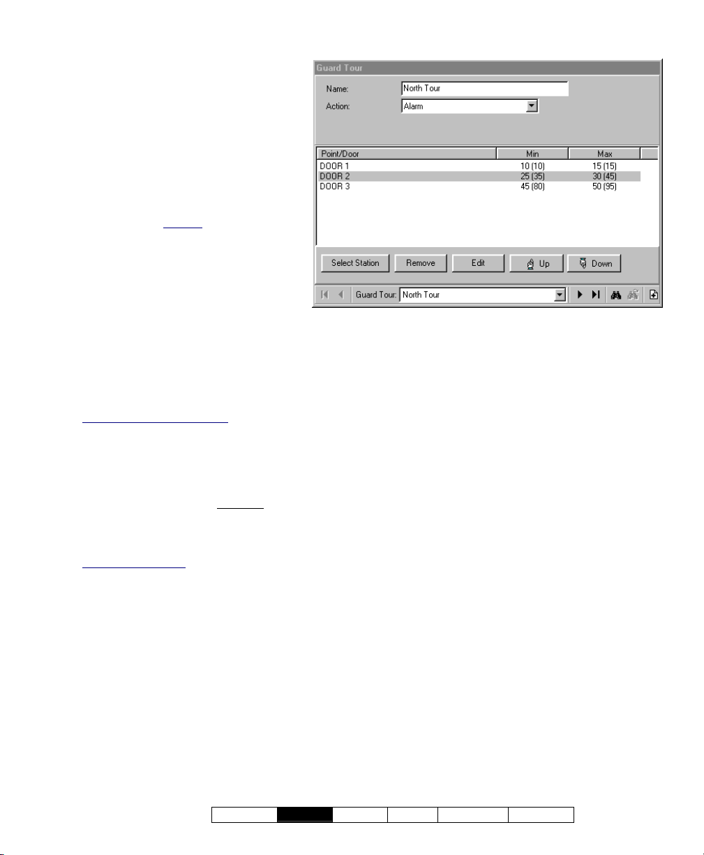
Guard Tours
- Guard Tour (bottom of form): This is
where you select a guard tour to view
or edit (or "New Tour" to add a new
one). This area shows a reference
number assigned by the system, and
the name of the guard tour, once
defined;
- Name: A suitable name / description
for the guard-tour.
Tip: Be sure to change this from the
default setting of "New Tour".
- Action: The actions to occur if the
guard is late or absent at one of the
checkpoints (whether to abort the tour,
trigger an alarm, and/or sound the
siren output on the specific panel);
- (Station / Checkpoint List): The main
portion of this screen shows the stations
(checkpoints) for the selected guard-tour, in the
order they occur. The minimum and maximum
times are also shown (both since the previous
checkpoint, and the total).
Area Arm/Disarm Commands: These trigger
automatically when the guard accesses the preceding
station within the allowed time.
- [Select Station]: Click this to allow adding
doors and guard-tour input-points to this guardtour, and setting the allowable time-range for the
guard to arrive from the previous
station /
checkpoint (in minutes);
This is the same as right-clicking the centre portion of
the form and selecting "Add New".
Multi-Panel Systems
tour can be set to display either as a single list, or on a
panel-by-panel basis. For details on these choices,
refer to "Other Desktop Choices".
: Items to be added to a guard-
- [Remove]: Click this to remove a selected
checkpoint (door or input-point) from the guardtour;
- [Edit]: Click this to allow changing an existing
checkpoint:
+ Selecting a different door or guard-tour input-point,
and/or;
+ Changing the allowable time-range for the guard to
access this checkpoint;
- [Up]: Moves a selected checkpoint up to an
earlier position in the guard-tour, while leaving
the time-range values as-is;
- [Dow n]: Moves a selected checkpoint down to a
later position in the guard-tour, while leaving the
time-range values as-is.
After changing the position of any stations (checkpoints)
in a guard-tour, be sure to always re-check the min/max
time values. (To change the times, select the item in
the guard-tour, click [Edit], and make your desired
changes, clicking [Ok] when finished.)
(Ö)
21-0381E v4.7.3
Welcome
Report Control Admin Sys Config Tech-Ref
51
Page 60
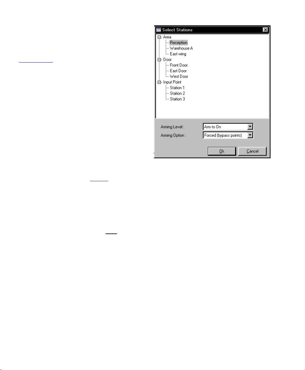
- Doors and Input Points (top of the form): This
is where you select the specific door or inputpoint pertaining to the guard-tour station being
added or changed;
Area Selections: See "Automatic Area Disarming /
Rearming", to follow / below.
To be available here, the specific areas and devices
must already be defined in the system. As well, guard
tour inputs must be set as a "Custom Point Type" with
the "Preprocess" set as "Guard Tour" (and the "Level"
set as "24 hours"). For details, refer to:
• "Doors, Readers, and Related Settings",
• "Input Points—Custom Point Types", and
• "Input Points—Monitored Sensors", as applicable.
- Minimum Time: The minimum allowable time
for the guard to reach this station (from the
previous one);
- Maximum Time: The maximum allowable time
for the guard to reach this station (from the
previous one);
Note: For the 1st station (i.e., the "Start Point"
selected under "Guard Tour Monitor"), the time is from
when the guard tour is activated (i.e., when the guard
tour is 'added' to the Guard-Tour monitor
-------------------------
screen).
Automatic Area Disarming / Rearming
If you select an area instead of a door or input
point, this allow s setting that area to disarm or
rearm automatically when the guard accesse s
the preceding station within the allowed time.
- Arming Level: For an area selection, this
provides area arm/disarm choices. Note
: "Arm
to Stay" will occur only if the area is disarmed
Guard Tours Ö[Select Station] (or [Edit] )
(Off); "Disarm to Stay" will occur only if the area
is fully armed (On).
- Arming Option: For an area selection, this sets
the type of arming (i.e., whether or not any
sensors (points) that are not 'OK' will be
automatically bypassed to allow the arming to
occur).
52 VEREX Director V4.73 User's Guide 21-0381E v4.7.3
Page 61

Checking Status and Controlling Items
21-0381E v4.7.3
Welcome Report
Control Admin S ys Config Tech-Ref
53
Page 62

Maps and Video (Visual Monitoring & Status/Control)
Status and Control Using Visual Director
Welcome to Visual Director (Map/Camera Views)
Beginning with V4.0, VEREX Director includes
a customizable visual interface for vie wing live
cameras, monitoring alarms, and controlling
items. We call this "Visual Director".
Software Licensing: This is an optional feature
(requires suitable software licensing). For details on
activating purchased features, refer to "Software
Activation and Licensing".
Camera Support
Netvision and other video servers. For more
information, refer to the on-line help or documentation
provided with the Netvision software.
Grid view
'forms' view only.
Initial Set Up / Camera Control and Adjustments
section covers using 'Visual Director' to perform
monitoring, status, and control tasks.
Also See
Adjustments", and "Initial Set Up of: Views, Maps,
Cameras" (both to follow / below).
Items to be available under Control & Status depend on
the authorities associated with the user
entered when logging into "Control & Status". If you
were not asked to enter a user ID and PIN, then one
has been set up for automatic entry in your operator
settings. For details, refer to the section on
"Operators".
Status monitoring (either manually, or through the
status toolbar), requires that the VEREX Director
system be connected with the specific panel(s), and the
specific devices must be communicating.
Also See (≥ V4.0):
+ For Form-based Status & Control:
"Checking Status and Controlling Items"
+ To Set up Panel Communications for a New System:
"New Installation? Try the Wizard "
: Cameras are supported through
: Due to its visual nature, this feature uses
: This
: "Camera Status/Control and
ID and PIN
Connecting to the Associated Panel(s), An Overview:
Tip: If you will only be viewing or controlling cameras,
you do not need to initiate a panel connection
(i.e., you can skip these steps).
1) See if you're already connected by
checking the status bar at the bottom of
the monitoring window.
Multi-Account systems: Ensure your desired
account is selected (click [Account Folders] in the
tree, and then double-click the specific account).
2) If not connected, check to ensure the
communication software is running on the
specific PCs.
Detail: If the LCD/Telephone icon on the
Windows taskbar is black-and-white (colour =
running), start the communications service by
right-clicking the icon, and selecting "Start
Communications".
Related Topic
(Communications Manager)
: Serial Port / Modem Setup
3) Selec t Communications from your
MyTools bar, or
click [Communications]
in the 'tree', and select Pending/OnLine.
4) Click the [+] at the bottom of the form, or
right-click the form, and select Add New
from the pop-up menu. Then, select the
desired panel(s) (double-click to select),
and set "Action" to "Normal", and
"Frequency" to "Stay Connected" (9).
(Click OK when finished.)
5) Check that the connection is made, and
watch for the panel updates to occur.
(Click the 'Panel Group', and look for the status on
the right side of the screen.)
Note: Control & Status features will be available after
the panel updates have finished (look for a connection
state of 'Connected' and 'Idle State'.)
Also See (Related Topics):
+ "Panel Communications and Updates"
54 VEREX Director V4.73 User's Guide 21-0381E v4.7.3
Page 63
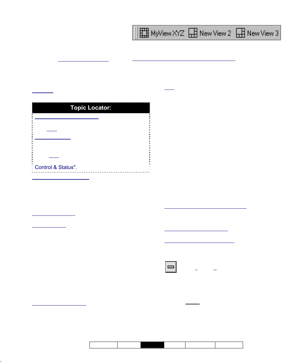
Accessing This Feature (Visual
The 'Views' Toolbar
Director)
See if you're already connected with
the panel(s) by checking th e status
bar at the bot tom of the monitoring
window.
select
and double-click the desired account.
Multi-Account Sy stems: First
[Account Fol ders] in the 'tree',
The "Views" toolbar provides access to all map/camera views
that are presently set up.
To show or hide the view-name text in the toolbar:
Right-click within the title-bar, and select "Show Button Captions".
Also See: "Initial Set Up of: Views, Maps, Cameras"
If not presently connected, initiate a
connection as described previously/above.
Exception: If you will only be viewing or controlling
cameras, you do not need to initiate a panel connection
Topic Locator:
Using the M yTools Bar : Select " Visual
Director" from the MyTools bar (and logi n with
your user ID and PIN if prompted for this).
Using the T ree: Click your site/account button
in the tree, open Control & Sta tus, and Panel
Control & Sta tus (click the " +"), and login with
your user ID and PIN if prompted for this.
Then, select " Visual Directo r" under "P anel
Control & Status".
If this feature is not present: This feature is available
only to operators with permission to access ALL
configuration topics. You may also need to upgrade
your software licensing.
Related + "Operator Permissions".
Topics: + "Software Activation and Licensing".
Multi-Panel Systems
panels (and cameras are not related to panels).
Automatic Login
automatically for a specific operator, refer to the section
on "Operators".
: Maps are not limited to individual
: To set the 'login' to occur
Selecting Views
When 'in' the visual-director screen, defined
map/camera 'vie ws' appea r on the "views
toolbar"
screen).
indicated with a flashing alarm-clock.
. ( Default P osition: T op-right corn er of the
Views that co ntain alarms are
To open a desired 'vie w', select it o n the
toolbar.
Event-Triggered Cameras: These appear in 'cameraviews' that show the last triggered camera (pertaining to
the specific 'camera-view'). Exception: This type of
window closes when you select a different 'view', or
move to a different screen/topic.
If you see a small down-arrow on the end of the toolbar,
you can click it to access additional map/camera views.
Note
: If your display mode is set to 800x600, you may
need to hide the view-names on the toolbar to allow
accessing the down-arrow. (Right-click the "Views"
toolbar, and deselect Show Button Captures.)
The bars on the left end of the toolbar allow you to drag
it to a new position if desired (in a fixed location, or
floating above the desktop). Tip: If you 'drop' it in an
undesired location, click [Restore] on the main toolbar.
Moving Around and 'Zooming' In or Out
To enlarge a map or camera image, doubleclick the image (a blank area). To return to the
previous size, click [Return].
Similarly, if your maps include links to cameras
and/or other maps, you ca n double-click a link
to view the image.
(Method 2: Right-click the link, and select Go to Link.)
When you're ready to go ba ck to the prev ious
map, click [Return].
If Area/Device Icons are Grey in Colour: This means
you are not connected with the specific panel or
account. For details, see: "Connecting to the
Associated Panel(s), An Overview" (previous/above).
If Camera(s) are Not Available
applicable Netvision capture station is not running.
Camera Control and Adjustments
or zoom any camera that supports Pan-Tilt-Zoom
operation. A number of other camera controls are also
provided.
QuickRef: (bottom of camera window).
Also: T
ools, ÖOptions, Ö(Visual Director )
Camera Status/Control and Adjustments
(a following section).
-------------------------
: This may mean that the
: You can easily aim
Full-Screen: To make th e Visual Dire ctor
window fill th e whole scre en, double-click its
title-bar twice
. (To return to normal, do ubleclick the title-bar once again, and click [Reset]
on the main toolbar.)
21-0381E v4.7.3
Welcome Report
Control Admin S ys Config Tech-Ref
55
Page 64

Zooming in or out on a m ap: Click the
desired map, then use one of these methods:
• Use your mouse scroll wheel, or;
• Use the (+) / (
the bottom, or
- ) (magnifying glass) buttons at
;
• Use the 'slider bar' on the right edge of the
screen, or
;
• Right-click a blank portion of the map. Then,
select Zoom, and your desired action.
To move around (scroll) w ithin a map , you
have 3 choic es. (1
st
click the desired map.)
Then:
• Click-and-drag a blank area on the map
(hold the mouse button down), or
• Use the scroll bars provided, or
;
;
• Use the "Universal Scroll" feature of your
mouse (if it is set up for this).
Tips: The map will automatically shift to display the
selected item. For status & control details, see a
following section / below.
When You Right-Click a Blank Spot on a Map
Zoom:
- Provides various selections for zooming in or out
on a map.
View:
- Show Zoom Slider: This sets whether or not
the 'zoom slider' will be displayed (allowing you
to zoom in and out visually).
- Show Item Text: This sets whether or not
descriptions will be shown for visual items on
maps.
Tip: Beginning with Director v4.66, this value is saved
independently for each operator.
Locating Items on a Complex Map, and Filtering to Show Fewer Items at a Time
To temporaril y limit a ma p to show only a
specific type of devices / objects:
3) Click within the desired map.
4) Click the small down-arrow to the right of
"Filter:".
Note: This is at the bottom of the map window (NOT
the [Filter] button at the bottom of the event/monitoring
window).
3) Select your desired topic from the popup menu.
Then, scan the map for your item(s) of interest.
If you cannot find the desired item on the map,
look for (and select) it in the item-list at the
bottom of the map window.
(If you still can' t find it, ensur e the desir ed item is not
filtered-out accidentally.)
Tip: The map will automatically shift to display the
selected item. For status & control details, see a
following section / below.
56 VEREX Director V4.73 User's Guide 21-0381E v4.7.3
Page 65
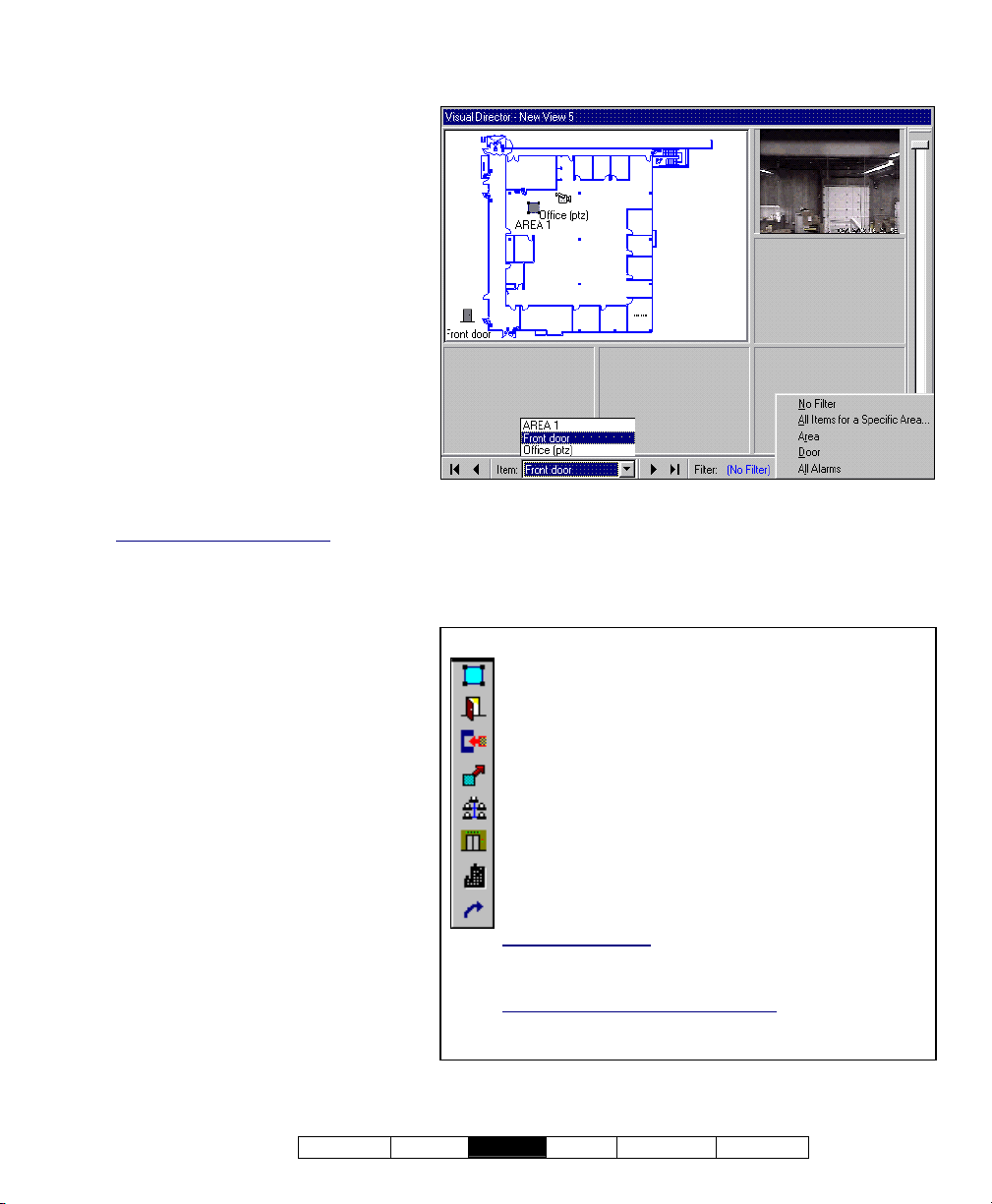
- Item (bottom of the form): This allows
Control & Status ÖPanel Control & Status
ÖVisual Director
you to find a specific item on a
complex map;
Tip: Making selections here is well-suited
for complex maps. For simpler maps, you'll
likely prefer to scan the map visually. For
status & control details, see a following
section / below.
- Filter: This allows temporarily limiting
a selected map to show specific types
of devices only (click the small downarrow to see the available choices).
Tip: Do not confuse this with the [Filter]
button at the bottom of the event/monitoring
window. Note: The filtering stays in effect
only until you select a different map (or any
topic outside of Visual Director).
- (+) / ( - ) (magnifying glass symbols) and
the 'slider bar' on the right edge of the
screen
: These allow zooming in or out
on a selected map.
To show or Hide the Slider Bar: Right-click a blank
area on the map. Then select "View", and "Show
Zoom Slider" from the pop-up menu.
21-0381E v4.7.3
Welcome Report
Item Legend
An Area (including all associated devices);
A Door and associated reader(s);
An Input Point (sensor);
An Output Point (electronically triggered device);
An Expansion Module;
An Elevator (lift) and associated reader;
A Suite-Security Keypad;
A link to a live camera, or another Map.
Flashing Green Box: This indicates a 'selected' item on a
map. (This pertains to navigating using the browse buttons at
the bottom of the screen.)
To show or Hide Item-Names on a Map
area on the map. Then select "View", and "Show Item Text"
from the pop-up menu.
Control Admin S ys Config Tech-Ref
: Right-click a blank
57
Page 66
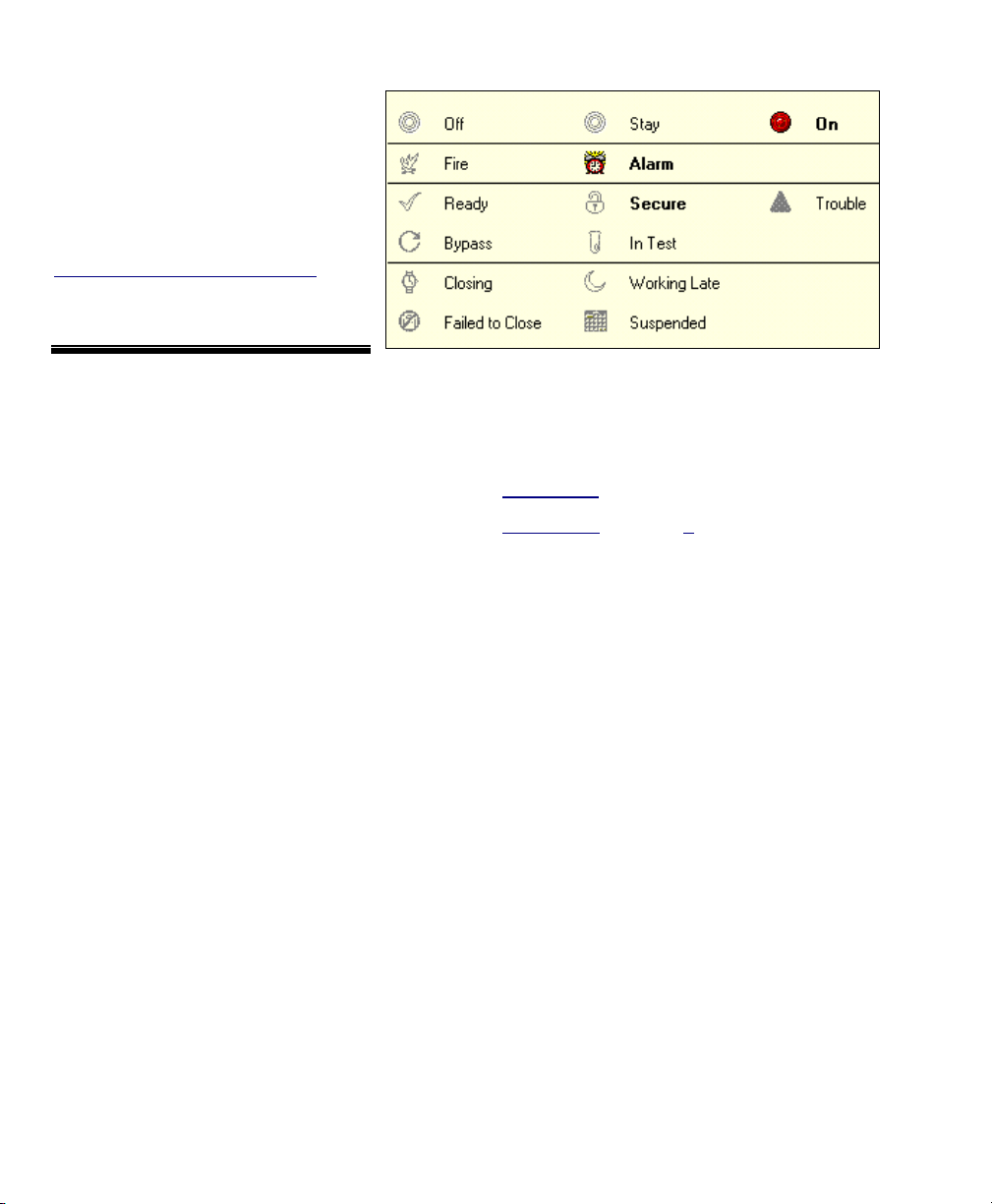
Viewing the Status of an Area or Device
Open the a pplicable "View", and
(locate) and select the desir ed device
(Details: Previous/above)
.
Then, 'hover' your mouse c ursor on
top of the ite m, and watch for a popup status screen.
Jumping to the Control & Status Form:
Right-click the area or device and select
"Switch to Control & Status Screen for this
Item" from the pop-up menu.
Area and Device Status (Mouse hovered over an item)
Various status aspects will be shown for the
specific area or device. If you require more
information on the listed information, look for an
applicable topic under "Checking Status &
Controlling Items".
User's Guide: Look in the table of contents near the
front of the manual.
On-Line Help
"Topics" (and ensure the Contents tab is selected).
If the Help is already open, select [Topics], and then
the Contents tab.
: Open the Help menu, and select
58 VEREX Director V4.73 User's Guide 21-0381E v4.7.3
Page 67

Controlling an Area or Device
Open the applicable "View", and (locate) and
select the desired device
Previous/above)
.
(Details:
Then, right-click the device and select your
desired action from the pop-up menu.
Jumping to the Control & Status Form: Right-click
the area or device and select "Switch to Control &
Status Screen for this Item" from the pop-up menu.
Dealing with Alarms
When an alar m occurs, alw ays verify what
caused it. Be sure to dispatch someone
to deal with any conditio ns that r equire
attention.
-------------------------
To silence an alarm, right-click the spec ific
'Area' on the map, and select Silence.
To set the event/monitoring window to show all
events associated with a de vice or area, rightclick the item and select " Resolve and Show
All E vents for This Item ". To view only t he
alarms associated with a device or area, right-
click the item and select "Resolve".
For more information on working with the monitoring
window, refer to "Monitoring System Activity".
-------------------------
To enter a co mment and s et a single-alarm
as having be en resolved ( or not), click the
coloured box on the left of the alarm
message. When the small screen appe ars,
enter a sui table comment and select
[Resolved] or [Keep Unresolved].
To enter a comment and set all
alarms for a
device or area as 'Resolve d' (or not), rig htclick the monitoring w indow and select
"Resolve All ". Then, e nter a suitable
comment, and select [Resolved] or [Keep
Unresolved].
21-0381E v4.7.3
Welcome Report
( Ö )
Control Admin S ys Config Tech-Ref
59
Page 68

___________________________________________
Common Commands--All Items
(After right-clicking the item)
------------------------------------------------------------------------
- Resolve (when alarms present): Sets the
event/monitoring window to show only the
present alarms for the selected area or device;
- Resolve and Show all Events for This Item
(when alarms present)
window to show all alarms and events for the
selected area or device;
To return the Event/Monitoring Window to Its Previous
State: Click [Return to Previous Filter] at the
bottom of the window.
- Switch to Control & Status screen for this
Item: This jumps you to the form-based
"Control & Status" screen for the selected item.
___________________________________________
: Sets the event/monitoring
Area Commands (After right-clicking an Area)
Also See: "Common Commands", previous/above.
-------------------------------------------------------------------------
- Off / Stay / On: These selections allow
manually arming or disarming the area (i.e.,
setting the arming level);
Tip: If any input points (sensors) are presently tripped
or bypassed, you will be guided though the steps to
deal with this first (bypass / acknowledge).
- Silence (when an item is in 'alarm'): This shuts off
the sounding of present alarms (i.e., shuts off
the system siren output, and LCD keypad
sonalerts).
- Worklate: This allows adjusting the area's
scheduled closing time in increments of 30
minutes.
- Lock All Doors in this Area: This locks all
doors with at least one reader associated with
the specific area;
- Unlock all Doors in this Area: This unlocks all
doors with at least one reader associated with
the specific area;
- Reset User Count In Area: This allows
resetting this area's "user-count" to zero.
Note: 'User-counting' is configurable for each area.
Ref: Configuration ÖAreas ÖActivity.
___________________________________________
Door Commands (After right-clicking a Door)
Also See: "Common Commands", previous/above.
-------------------------------------------------------------------------
- Lock: This locks (re-locks) the specific door.
- Unlock: This unlocks the specific door.
- Momentary Normal Unlock: This unlocks the
door for a duration equal to the standard "unlock
duration". This is the same as someone gaining
entry with an access card or token.
- Momentary Extended Unlock: This unlocks
the door for a duration equal to the "extended
unlock duration". This is the same as a user
who is set for "extended unlock/challenged"
gaining entry with an access card or token.
- Pending Unlock: This is an unlock command
that waits for one person to enter the facility at
the specific door.
- Grant Last User -- Reader 1 (or 2): If the last
user at a reader was denied access, this will
issue a 'Momentary Unlocking', and log that
card/user as being granted entry.
• Cards can be denied due to being expired, locked
out, wrong time, wrong door class, etc. -- as long as
they are defined in the system.
• This feature will be unavailable if someone else is
granted entry, or after 5 minutes from the time the
person was denied access (although they can
simply present their card/token again).
• This may be used in conjunction with an event-
triggered camera-view for the door (so a remote
attendant can see the person).
Related Topics
Cameras" (step 3b).
• This can also be used in conjunction with the pop-
up "Photo-Verification" feature (if it is set to trigger
on 'Access Denied' events).
Related Topics
Verification)"
• Thi s cannot
- Cards being enrolled or disabled at a reader set to
do this (although it will apply for cards denied due
to wrong area/time, etc.);
- Access being denied due to door interlock
violations or area/disarm authority issues.
: "Initial Set Up of: Views, Maps,
: Visually Verifying Users (Photo-
be used (or does not apply) with:
60 VEREX Director V4.73 User's Guide 21-0381E v4.7.3
Page 69

___________________________________________
Input-Point Commands
(After right-clicking a Sensor)
Also See: "Common Commands", previous/above.
-------------------------------------------------------------------------
- Bypass / Remove Bypass: "Bypass" allows
arming an area with a tripped or faulty input
point (sensor). "Remove Bypass" allows
monitoring the input point again (for a sensor
that is "OK").
____________________________________________
Output-Point Commands
(After right-clicking an Output/Device)
Also See: "Common Commands", previous/above.
--------------------------------------------------------------------------
Tips
: First, select "Manual Output Control".
Additional parameters appear when applicable
(duration, etc.).
- Normal: No manual control (i.e., return to
normal operation);
- Always: Allows setting the output as On
continuously (until manual control is removed);
- Momentary: Allows setting the output to
pulse/toggle once. Additional selections will
appear for: • Whether it is to be triggered On
(high), or Off
afterwards (Off
(Low); • The state it will be left in
, On, or Normal); • How long the
relay will remain triggered (1 second to 1 week).
- Duty Cycle (1 sec. On/1 sec. off): The output
will be pulsed on and off continuously for a
selected duration (1 second to 1 week).
___________________________________________
or Off
Elevator Commands
(After right-clicking an Elevator)
Also See: "Common Commands", previous/above.
-------------------------------------------------------------------------
- Secure / Desecure: This allows applying or
removing controlled-access for all floors as
accessed from the specific elevator (lift).
(Secure: An access card or token provides access to
specific floors; • Desecure
floor without a card or token.
Controlling a Floor (as accessed from all cabs): Refer
to "Checking Status or Controlling Floors"
: Anyone can access any
21-0381E v4.7.3
Welcome Report
Control Admin S ys Config Tech-Ref
61
Page 70

Camera Status/Control and Adjustments
Introduction
A number of camera controls are provided,
allowing you to: • Aim or z oom PTZ cam eras;
• Check conn ection status; • Adjust image
quality, etc. These features are pro vided
through the video toolbar in each ca meraimage, with additional camera s ettings
available under: T
ools, ÖOptions.
The Video Toolbar
When working in a 'v iew' that contain s a
camera-image, a small button in the bottomleft corner will provide acc ess to the v ideo
toolbar.
To use this feature, refer to the itemdescriptions for the video toolbar, plus the
sections that follow.
Note: The video toolbar is available when viewing or
customizing maps, but not when setting up 'Views'.
(Show Video Toolbar)
- Hide Video Toolbar: Closes/hides the video
toolbar;
- Change View Size: Allows setting the
maximum displayed image size for a camera
(details to follow);
- View Messages: Allows viewing the
camera/PTZ connection status for the camera
(details to follow);
- Start PTZ: Allows working with a PTZ camera
(details to follow);
62 VEREX Director V4.73 User's Guide 21-0381E v4.7.3
Page 71
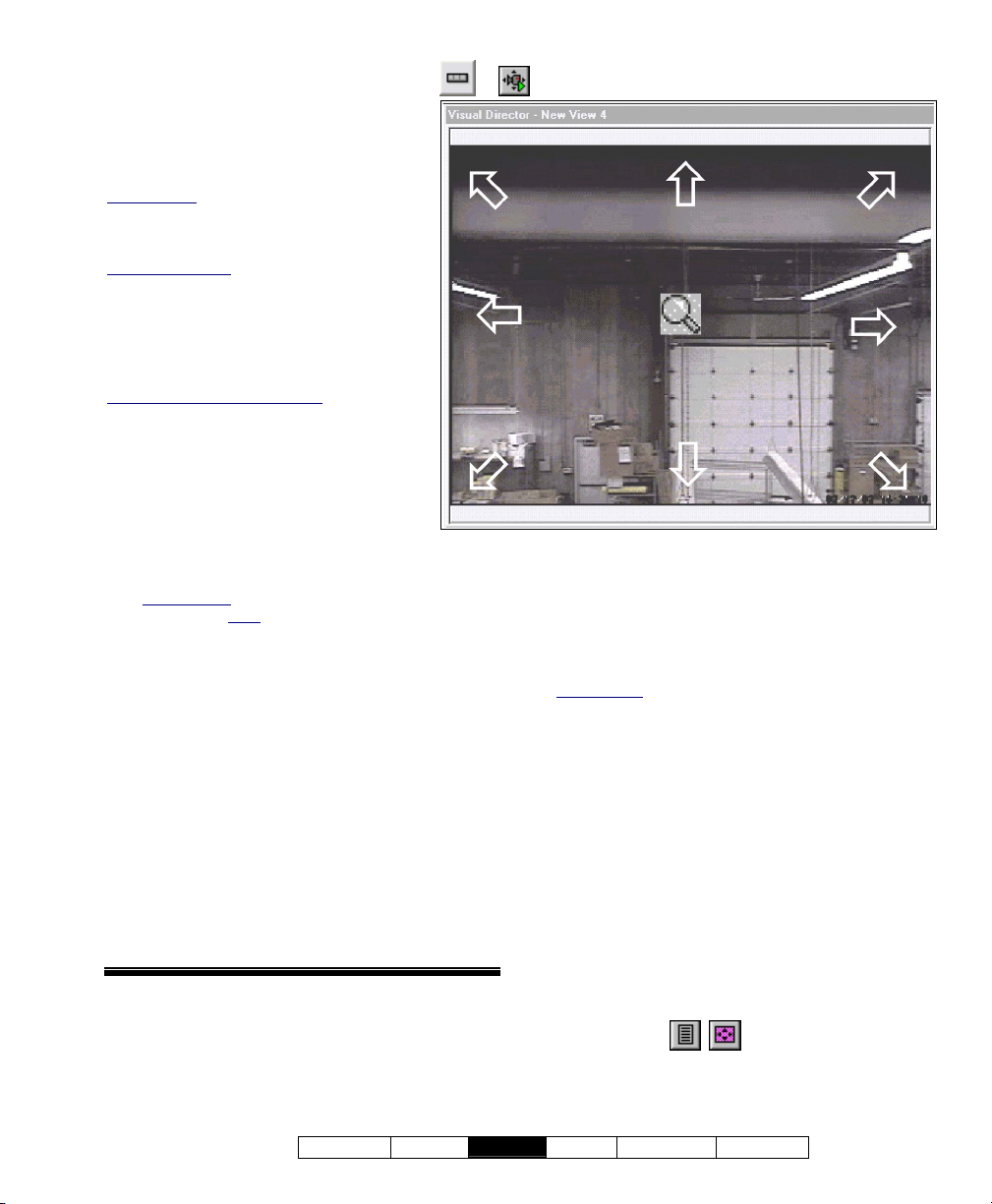
Controlling a Pan/Tilt/Zoom Camera
You can ea sily aim or z oom any
camera that supports Pan-Tilt-Zoom
operation.
Initial Set Up: PTZ cameras must be
identified and properly set up. Details:
Step 1b: Define Cameras (under "Initial Set
Up of: Views, Maps, Cameras", to follow).
User Permissions
control a specific PTZ camera (COM port) at
a time. Who will get access is based on:
• The username assigned to the camera
during initial set up;
• PTZ user priorities defined at the capture
station (for each PTZ username).
Event-triggered 'camera-views'
PTZ cameras is not supported in eventtriggered 'camera-views'--although you can
use a 'view' that contains the specific camera
(or a link to the camera) to access PTZ
control.
Steps:
: Only one person can
: Control of
1) Open the 'View' that contains the
desired camera-image.
MyTools Bar: Visual Director (+User login if
prompted). Tree
Control & Status (+User login if prompted),
ÖVisual Director.
Then, select from the 'Views' toolbar (top-right).
: Control & Status, ÖPanel
2) Open the video toolbar by clicking the
button in the bottom-left corner of the
camera-image. Then, click the 4th button
("Start PTZ").
3) 'Hover' your mouse around the camera-
view, and watch for the cursor to change
to an arrow or magnifying glass.
4) Click (or click and hold) the image with
the cursor indicating your desired
action.
For options and more information, refer to
the screen image and item-descriptions.
Ö ÖThen hover over the Camera-Image
- For cameras that support pan-tilt-zoom (PTZ)
control, your mouse cursor will change to
indicate different pan-tilt-zoom directions as you
move around the camera-view. (Click, or click-
and-hold with the mouse indicating the desired action.)
To zoom out: Right-click-and-hold near the centre of
the screen (magnifying glass).
- Adjust PTZ Speed: After clicking "Start PTZ",
an additional button will appear on the right
which allows opening the PTZ speed control.
The length of the blue bar indicates the present
relative speed. To adjust the speed click a new
position on the speed indicator bar, or click the +
/ - symbols at either end.
- X: This closes the PTZ speed control, and
returns you to the camera-image.
21-0381E v4.7.3
Welcome Report
Ö
Control Admin S ys Config Tech-Ref
63
Page 72
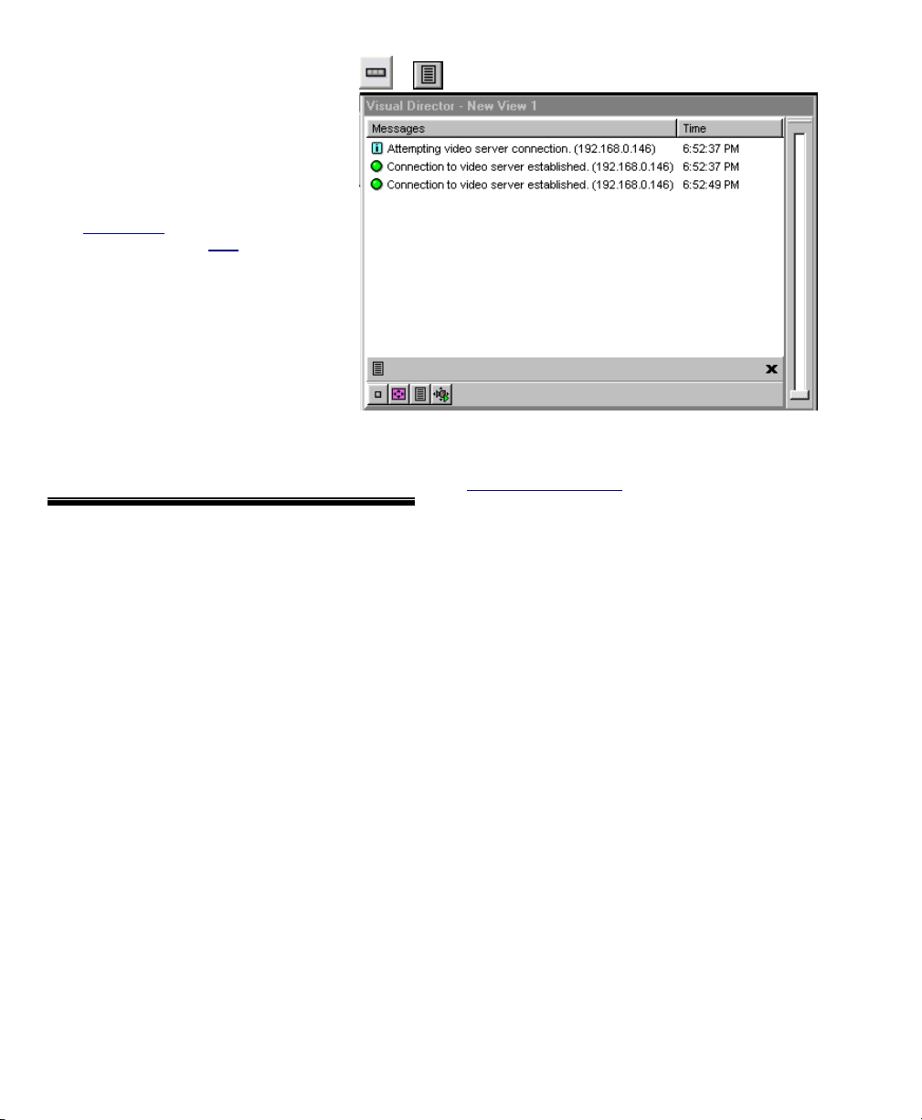
Checking Camera/PTZ Connection Status
Camera and PTZ connection status
can be viewed at any time.
Steps:
1) Open the 'View' that contains the
desired camera-image.
MyTools Bar: Visual Director (+User
login if prompted). Tree
Status, ÖPanel Control & Status (+User
login if prompted), ÖVisual Director.
Then, select from the 'Views' toolbar
(top-right).
: Control &
2) Open the video toolbar by
clicking the button in the
bottom-left corner of the
camera-image. Then, click the
3rd button ("View Messages").
For more information, refer to the itemdescriptions for this screen.
Ö
- This screen shows the connection status for the
camera being viewed.
Flashing Yellow Symbol: When a problem occurs
(such as PTZ timeout), the 'View Messages' button will
appear with a warning symbol.
- X: This closes the status window and returns
you to the camera-image.
64 VEREX Director V4.73 User's Guide 21-0381E v4.7.3
Page 73
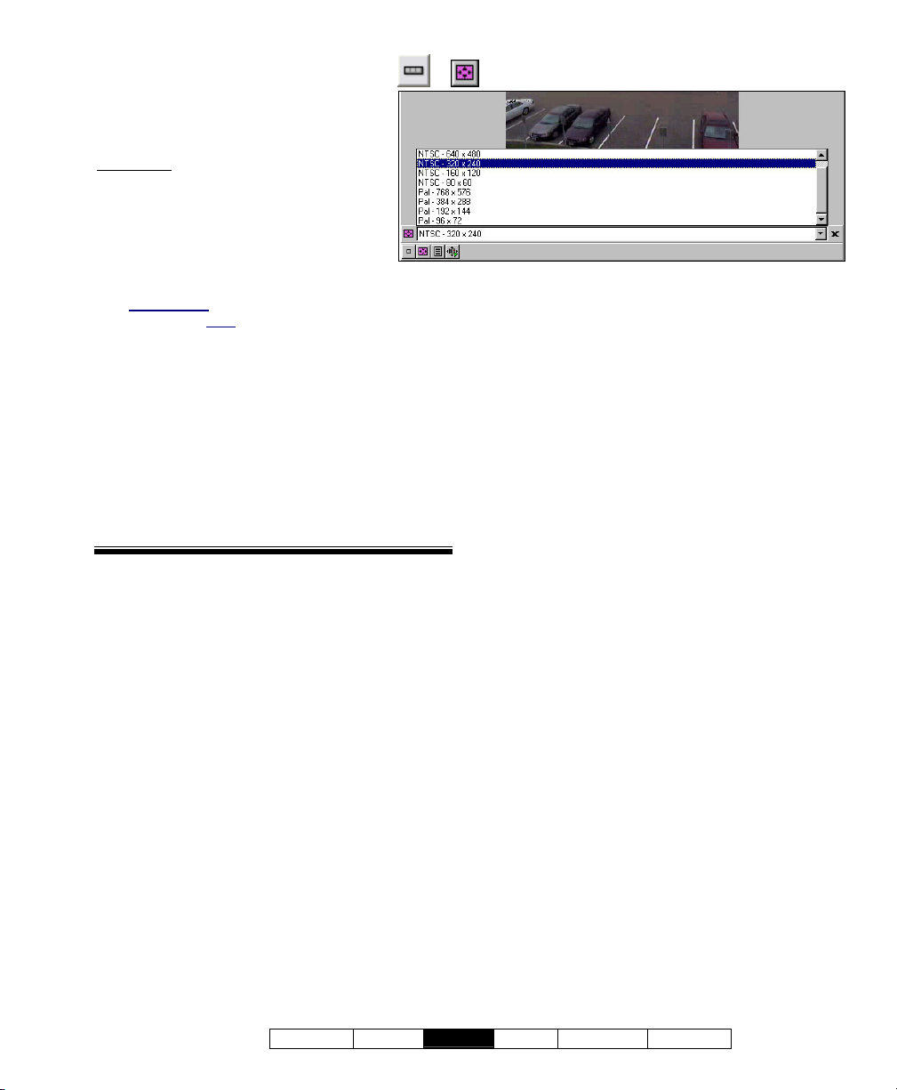
Setting the Maximum CameraImage Size
Camera-images auto-size relative to
the window they are displayed in.
Exception
: T o avoid jagge d looking
images, you can set the maximum
displayed image-size for each
camera.
Steps:
1) Open the 'View' that contains the
desired camera-image.
MyTools Bar: Visual Director (+User login if
prompted). Tree
Control & Status (+User login if prompted),
ÖVisual Director.
Then, select from the 'Views' toolbar (top-right).
: Control & Status, ÖPanel
2) Open the video toolbar by clicking the
button in the bottom-left corner of the
camera-image. Then, click the 2nd button
("Change View Size").
3) Click the down-arrow on the right to open
the list and make your selection.
For more inf ormation, refer to the itemdescriptions for this screen.
Ö
- This screen allows setting the maximum
displayed image-size for the camera being
viewed.
- X: This closes the image-size control, and
returns you to the camera-image.
21-0381E v4.7.3
Welcome Report
Control Admin S ys Config Tech-Ref
65
Page 74
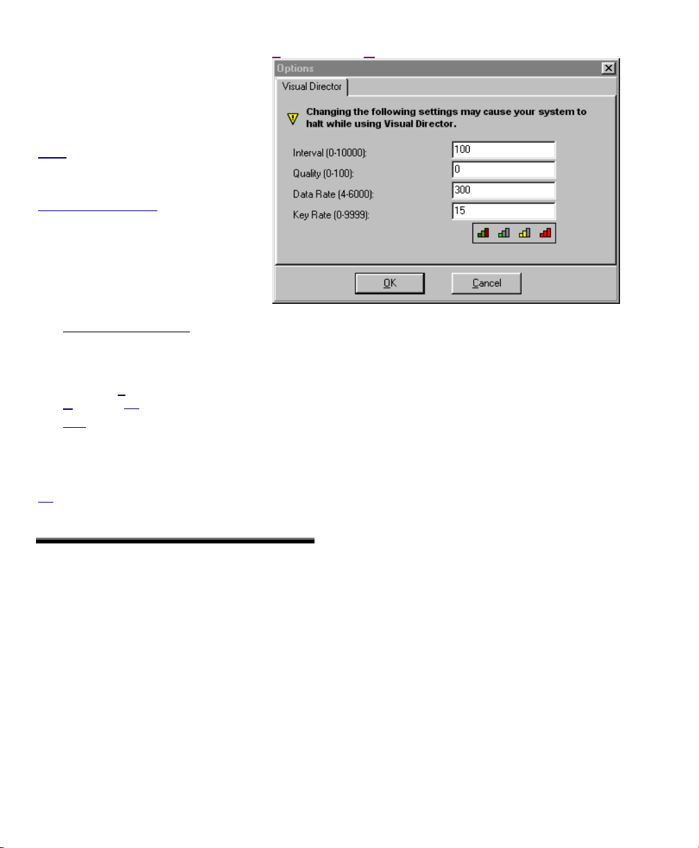
Adjusting Camera Quality for
Tools (menu) ÖOptions Ö(Visual Director )
your Connection/Bandwidth
Various c amera-Image quality
settings are provided to allow for
slower conn ection spee ds and
reduced-bandwidth applications.
Notes: These selections affect all cameras
for the selected account. Features
pertaining to maps and cameras are not
supported with single-panel licensing.
Maximum Image Quality
are transmitted based on the recording mode
at the NetVision capture station (if presently
being recorded there), or per the present/last
displayed image size for any camera on the
same capture board displayed at the capture
station.
: Camera images
Steps:
1) Multi-Account Systems: Ensure
you are 'in' the desired account.
(Click [Account Folders] in the 'tree', and
double-click the specific account.)
2) Open the Tools menu, and select
O
ptions. (Tip: If not listed, see step 1).
Note: If the "Options" screen contains only an
'Autostart' option, this means you have singlepanel licensing (maps/cameras not supported).
3) Refer to the selection-descriptions for this
screen while making your selections.
Tip: The easiest way to change these settings is using
the coloured buttons across the bottom. See "Coloured
Buttons" for details.
- Interval: Sets the duration between camera
image requests--in milliseconds (1000 = 1 frame
per second).
- Quality: Sets the relative amount of video detail
to be included in non-key frames. Also see "Key
Rate", to follow.
- Data Rate: This is a bandwidth control property
that determines the maximum video data
transmission rate.
(Defaults: Low = 56, Medium = 220, High =
3000).
- Key Rate: This determines how often a
complete frame is sent compared to only
changes from the previous frame. Lower values
provide better image quality and require more
bandwidth
-------------------------
- Coloured Buttons: These buttons provide
(from left to right): A quick way to return to:
• General default values, or;
Select pre-defined defaults suitable for:
• Low, • Medium, or; • High available
bandwidth (i.e., dial-up connection, DSL/cable,
or local network).
66 VEREX Director V4.73 User's Guide 21-0381E v4.7.3
Page 75

#
21-0381E v4.7.3
Welcome Report
Control Admin S ys Config Tech-Ref
67
Page 76
Initial Set Up of: Views, Maps, Cameras
Introduction to Map/Camera Set Up
"Views" and "Maps" must be set up before
visual monitoring and/or status & control tasks
can be performed.
Notice: It is extremely useful to familiarize yourself
with the operation of this feature, and plan how you
want your views and maps set up before you begin.
Grid view
'forms' view only.
Permissions: Setting up maps, cameras, and 'views'
requires an operator with permission to "Configure
Visual Director". This permission is also required to
change camera image quality/sizing (right-click menu).
: Due to its visual nature, this feature uses
Supported Map File Formats
Map images to be used with this feature must
have been saved in one of these file-formats:
• Vector/Drawing Formats: WMF, EMF
• Bitmap/Photo Formats: BMP, JPG
Note: Scalable graphics work best (EMF, WMF), and
are recommended--especially for more detailed maps.
Requirements for Camera Viewing
Camera vie wing (and PTZ cont rol) is
supported through Netvision capture stations.
DVR Types: Supported video servers include:
NetVision (V2.1 or V2.2 and newer)
Yes (via "Visual Director")
March R4 & R5
Optional via licensing (beginning with V4.7).
VeDVR / NVe (embedded)
Optional via licensing (beginning with V4.71).
Note: Playback for video events is NOT supported for
March R4 DVRs.
Required Items:
• TCP/IP protocol must be installed and set up
on your PC
as part of the MS Windows installation)
(this is typically done automatically
;
• You must have an available connection to a
network, the internet, or "dial-up networking"
to allow connecting with the capture station;
(And the capture station PC and software must be
running.)
• The IP address (or name) of each specific
capture station PC must be known;
• The capture station "Video Server" must be
set to allow anyone to view cameras
the Windows Control Panel)
;
(through
• The desired camera number should be
known;
• For control of PTZ cameras (pan-tilt-zoom),
you will need to have a valid PTZ username
for each specific capture station.
For details on setting up a Netvision capture station,
refer to the on-line help or other documentation
provided with the Netvision software.
68 VEREX Director V4.73 User's Guide 21-0381E v4.7.3
Page 77
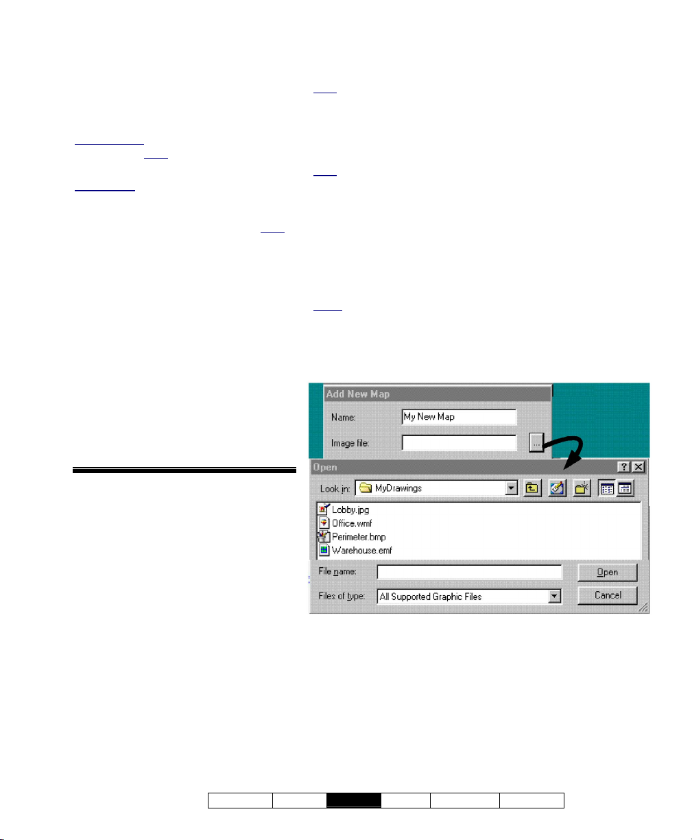
Step 1a: Define Source Maps
Map image files need to be identified
to the syste m before they can be
displayed.
Topic Locator:
MyTools Bar
: Customize Views,
(login with a user name & ID if needed),
select the Maps .
In the Tree
: Click your site/account
button in the tree, open Control &
Status, and Panel Control & Status
(click the "+"), and login with your user
ID and PIN if prompted for this. Then,
select: "Visual Director" (click the "+"),
ÖCustomize Views, ÖMaps.
Multi-Account Systems: First select
[Account Folders] in the 'tree', and doubleclick the desired account.
Click [Add] to set up a ne w map, or
right-click an existing one and select
Edit Map . Then, set the name as
desired, and click [...] to browse for a
desired image file
[Open] )
See the selection-descriptions for more
information (especially "Create Duplicate
Map").
.
(select the file and click
Visual Director ÖCustomize Views ÖMaps
- [Add]: Allows identifying a new map image;
Note: Scalable graphics work best (EMF, WMF), and are
recommended--especially for more detailed maps.
- [Delete]: Allows deleting an existing map from the list.
After Right-clicking an Existing Map in the List
- Add New Map: Allows identifying a new map image;
Note: Scalable graphics work best (EMF, WMF), and are
recommended--especially for more detailed maps.
- Edit Map: Allows changing the name or source file for a map
that has already been identified to the system;
- Create Duplicate Map: When areas and devices are added
to a specific map (step 3a, to follow/below), all views that use
the same map will show the same items. "Create Duplicate
Map" allows setting up different maps based on the same
image file.
Notes: For a map with devices already placed on it, the device
placement will be copied as well (delete/change these as desired).
- Delete Map: Allows deleting an existing map from the list.
Visual Director ÖCustomize Views ÖMaps
Ö[Add]
(or right-click a map in the list, and select "Edit Map")
21-0381E v4.7.3
Welcome Report
- Name: Enter a suitable name for the map. (This will typically
refer to the location or department associated with the image.)
- Image File: This is the location (path) and filename of the
map image file. Tip: Click [...] to browse for the file.
(Select the file and click [Open] ).
Control Admin S ys Config Tech-Ref
69
Page 78

Step 1b: Define Cameras
Cameras need to be identified before they can
be displayed by the Director software.
Topic Locator:
MyTools Bar: Customize Views, (login with a
name & ID if needed), select Cameras .
user
In the Tree
: Click your site/account button in
the tree, open Control & Status, and Panel
Control & Status (click the "+"), and login with
your user
ID and PIN if prompted for this. Then,
select: "Visual Director" (click the "+"),
ÖCustomize Views, ÖCameras.
Multi-Account Systems: First select [Account
Folders] in the 'tree', and double-click the desired
account.
Click [Add] to identify a ne w camera, or rightclick an e xisting one and s elect Edit Ca mera.
Then, refer to the selection -descriptions w hile
entering values for this camera.
-------------------------
Also See: Once the cameras and views have been set
up, you can easily aim or zoom any camera that
supports Pan-Tilt-Zoom operation. A number of other
camera controls are also provided.
QuickRef: (bottom of camera window).
Also: T
ools, ÖOptions, Ö(Visual Director )
Camera Status/Control and Adjustments
(previous).
Note
: The video toolbar is available when viewing or
customizing maps, but not when setting up 'Views'.
Visual Director ÖCustomize Views
ÖCameras
- [Add]: Allows identifying a camera to the
system.
- [Delete]: Allows deleting an existing camera
from the list.
After Right-clicking an Existing Camera
in the List
- Add New Camera: Allows identifying a camera
to the system.
- Edit Camera: Allows changing the name and
other information for a camera that has already
been identified to the system.
- Create Duplicate Camera: This saves some
time for additional cameras from the same
capture station (i.e., you won't have to re-type
the capture station IP address). After using this
selection, right-click "Copy of
the list, select "Edit Camera", and set the name
and camera number as desired.
- Delete Camera: Allows deleting an existing
camera from the list.
CameraName" in
70 VEREX Director V4.73 User's Guide 21-0381E v4.7.3
Page 79
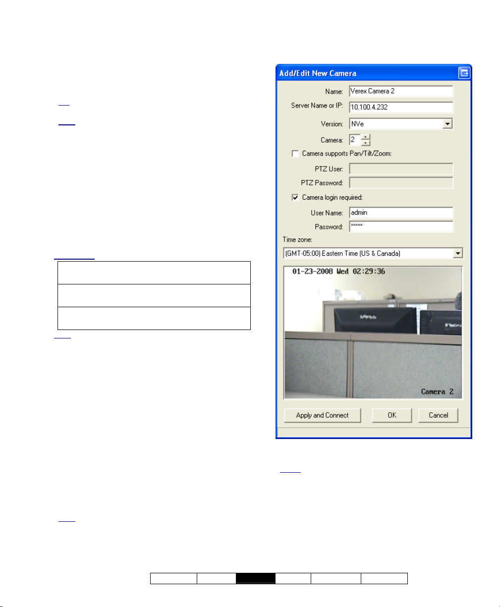
- Name: Enter a suitable name for the camera.
- Server Name or IP: This is the IP address (or
PC name) of the specific Netvision capture
station;
Tip: This can be an IP address, or a name (FQDN).
Contact your IT rep. for assistance if needed.
Note
: To view cameras, a connection must be
available. If unsure, go to a command prompt and try
'pinging' the IP address.
- Camera: This is the camera number/ID as seen
from its capture station;
-------------------------
- Camera Supports Pan/Tilt/Zoom: Select this
to allow PTZ control for a camera that supports
this;
Tip: For a non-PTZ camera (or if PTZ control is not
desired), ensure this is NOT selected.
- Version: Select the type of DVR (video server)
here.
DVR Types: Supported video servers include:
NetVision (V2.1 or V2.2 and newer)
Yes (via "Visual Director")
March R4 & R5
Optional via licensing (beginning with V4.7).
VeDVR / NVe (embedded)
Optional via licensing (beginning with V4.71).
Note: Playback for video events is NOT supported for
March R4 DVRs.
- PTZ User: Enter a valid remote user name
(with permission to control PTZ cameras) as set
up at the specific capture station.
- PTZ Password: Enter the login password for
the 'PTZ User'.
-------------------------
- Camera Login Required: Select this if the
NetVision capture station is set to only allow
registered users to view cameras (i.e., NOT set
to allow anyone to access the video server).
- User Name: Enter a valid remote user name
(with permission to view cameras) as set up at
the specific capture station.
- Password: Enter the login password
associated with the 'User Name' entered above.
Note: For a PTZ camera, the same user name and
password is typically used for viewing cameras and
PTZ-control.
- Timezone: For embedded DVRs (e.g., VeDVR
/ NVe). Select the timezone associated with the
Visual Director ÖCustomize Views
ÖCameras Ö[Add]
list and select "Edit Camera")
DVR unit here.
Notes: This setting is used with video events. For
other types of DVRs, this is handled internally, and this
field will be greyed-out.
- (camera display area): A sample image from
the selected camera indicates a valid
connection. (See next item.)
- [Apply and Connect]: Click this button to verify
the camera connection and display a sample
image.
(or right-click a camera in the
21-0381E v4.7.3
Welcome Report
Control Admin S ys Config Tech-Ref
71
Page 80
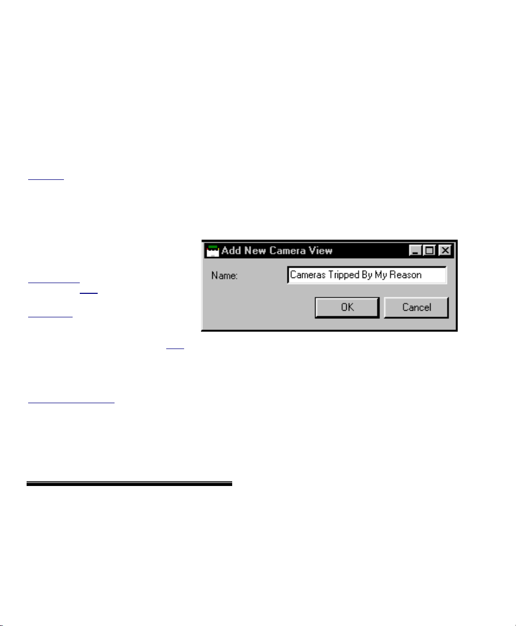
Step 1c: Define Camera-Views
(this is required only for event-triggered
camera-views)
As an altern ative to fix ed cameras
Visual Director ÖCustomize Views
ÖCamera-Views
- [Add]: Allows creating a new camera-view.
- [Delete]: Allows deleting an existing camera-view.
appearing in different locations onscreen, camera-views can be thought
of as 'lo cators' that allo w you to se t
where spec ific types of eventtriggered camera images will appear
(separately for each 'vie w'). Each
camera-view shows the last-triggered
camera associated with it.
Exception: Camera-views close when you
select a different 'view', or move to a
different screen/topic.
Tip: Be sure to create additional cameraviews for cameras that are to appear in
different locations on-screen.
(For more information on this feature, and to
assign a camera-view and camera to each
device, see step 3b.)
After Right-clicking an Existing Camera-View in
the List
- Add New Camera-View: Allows creating a new camera-view
(same as clicking the [Add] button).
- Edit Camera-View: Allows changing the name for a camera-
view that was defined previously.
- Delete Camera-View: Allows deleting an existing camera-
view.
Notice: This will disable the event-triggered camera display feature
for any doors and input points that are using this camera-view.
Visual Director ÖCustomize Views ÖCameraViews Ö[Add]
"Edit Camera-View")
Topic Locator:
MyTools Bar
: Customize Views,
(login with a user name & ID if needed),
select Camera-Views .
In the Tree
: Click your site/account
button in the tree, open Control &
Status, and Panel Control & Status
(click the "+"), and login with your user
ID and PIN if prompted for this. Then,
select: "Visual Director" (click the "+")
ÖCustomize Views,
ÖCamera-Views.
Multi-Account Systems: First select [Account
Folders] in the 'tree', and double-click the desired
account.
- Name: Enter a suitable name for the camera-view. This will
pertain to your specific needs and preferences (e.g., Doors,
Motion-Detectors, Sensors in Area X, Button ABC pressed,
etc.).
Click [Add] to define a ne w camera-view, o r
right-click an ex isting on e and select Edit
Camera-View. Then, set the name as desired
(see the name description for details).
(or right-click one in the list and select
72 VEREX Director V4.73 User's Guide 21-0381E v4.7.3
Page 81
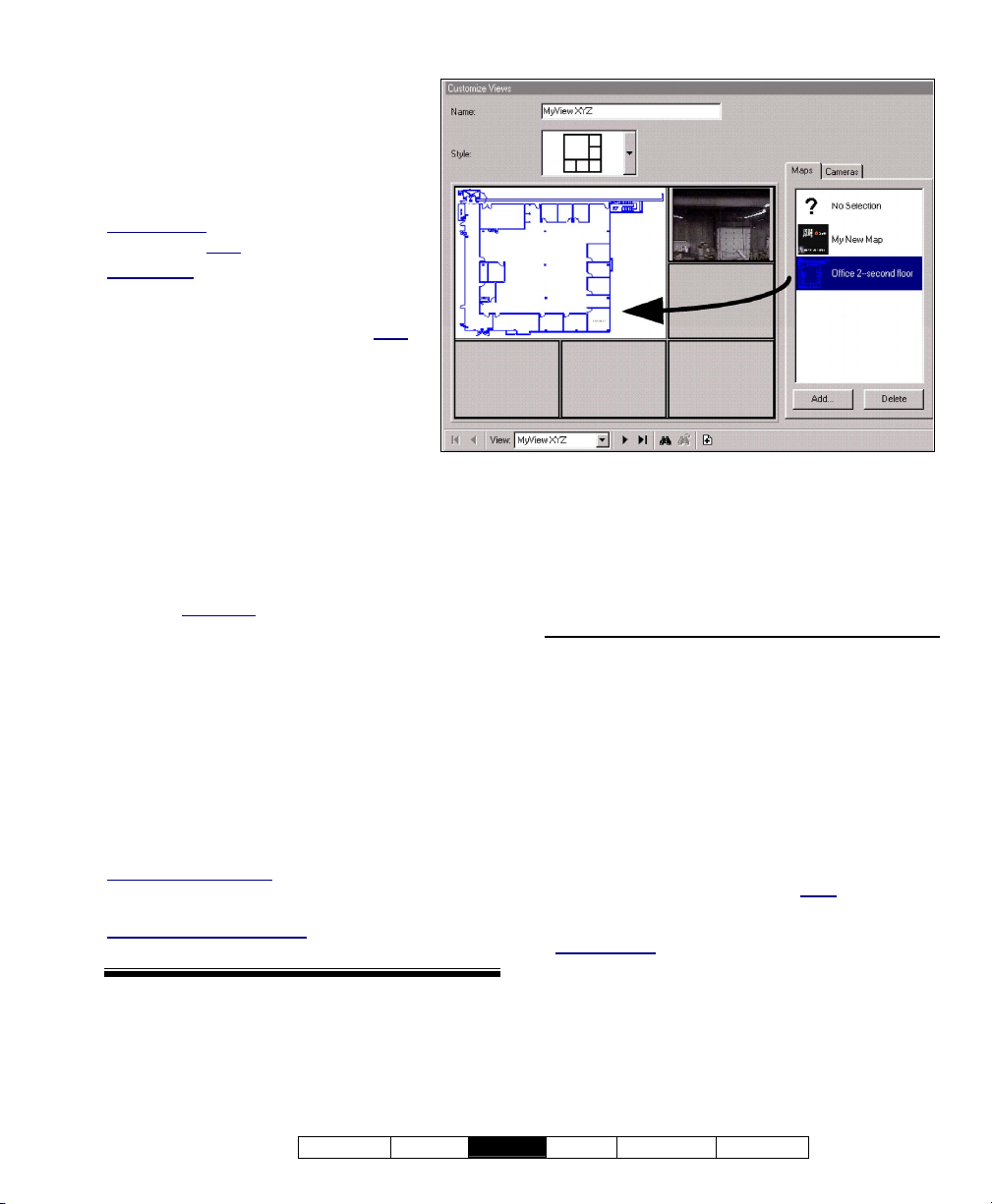
Step 2: Set up Views
Visual Director ÖCustomize Views
"Views" are definable layouts for
maps and ca mera images. These
must be set up to allo w viewing maps
and/or cameras.
Topic Locator:
MyTools Bar
(login with a user
In the Tree
: Customize Views, and
name & ID if needed).
: Click your site/account
button in the tree, open Control &
Status, and Panel Control & Status
(click the "+"), and login with your user
ID and PIN if prompted for this. Then,
select: "Visual Director" (click the "+"),
ÖCustomize Views.
Multi-Account Systems: First select
[Account Folders] in the 'tree', and doubleclick the desired account.
Tip: For additional space, it's a good idea to
turn off the event/monitoring window when setting up
'Views'. (Click [Events] on the main toolbar.)
-------------------------
Creating a New Vie w: Click [+] at the
bottom of the form, or right-click the for m,
and select Add Ne w View from the pop-up
menu.
View" from the list (bottom of the window).
Alternative: You can also select " New
Changing an E xisting V iew: Select the
desired "Vie w" from the p op-up list at the
bottom of the window.
Searching for an Existing Vie w: Click t he
'binoculars' symbol. Then, enter the na me
(or the first few characters + " ∗" ), and click
[Find].
Then, refer to the selection -descriptions f or
this screen while vie wing or chan ging
settings as desired.
To Copy an Entire View: Right-click, "Copy View";
right-click, "Add New View"; right-click, "Paste View".
Then, change the name and other items as desired.
If you Need to Delete a View
area on the view, and select "Delete View".
: Right-click a blank
- View (bottom of the form): This allows
selecting an existing 'View' (or select "New
View" to set up a new one).
On This Form
- Name: This is a description for the displayed
map/camera view;
- Style: This is a basic layout style for the
displayed map/camera view (the centre of the
screen will change per your selection);
Maps , Cameras , and
Camera-Views
These 'tabs' show a list of the presently defined
Maps and Cameras. Click-and-drag items to the
desired location.
Tip: For items that have already been placed on the
left, you can click the item to have it identified on the
right. (Try it! )
To remove an item from a 'view', drag the item back
into the list (or drag to item called "No Selection" to the
item's location).
Notes: Each item can appear only once
single view. The software will attempt to connect with
cameras right-away.
Camera-views
types of event-triggered camera images will appear
(for each view that uses this feature). Each cameraview shows the last-triggered camera associated with
it. Be sure to use additional camera-views for
cameras that are to appear in different locations onscreen. (For more information, see step 3b.)
: These allow you to set where specific
within a
21-0381E v4.7.3
Welcome Report
Control Admin S ys Config Tech-Ref
73
Page 82
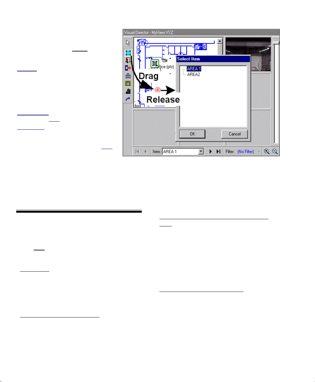
Step 3a: Place Items onto Maps
Visual Director ÖCustomize Maps
(Doors, Sensors, etc.)
Customizing maps pertains to placing
objects on specific maps
t o enable
visual monitor ing, and st atus/control
features.
Attention: Items added to a specific map
here will appear on that map in every 'view'
that contains it. (To avoid this, you can copy
a map and save it as a new one, or create
new map(s) using the same image file. For
details, see step 1a.)
Topic Locator:
MyTools Bar: Customize Maps, and
(login with a user
In the Tree: Click your site/account
button in the tree, open Control &
Status, and Panel Control & Status
(click the "+"), and login with your user
ID and PIN if prompted for this. Then,
select: "Visual Director" (click the "+"),
ÖCustomize Maps.
Multi-Account Systems: First select [Account
Folders] in the 'tree', and double-click the desired
account.
name & ID if needed).
Then, refer to the details for this screen while
viewing or changing settings as desired.
This screen shows your selected view with its
associated maps and cameras, along with the
areas and devices that have been placed on
each map (so far).
To select (or search for) a desired 'view', see step 2
(previous/above).
Navigating: You can enlarge (double-click),
and zoom/scroll within maps as desired.
For details on: What the Device Icons mean, and
how to scroll and zoom within a map, refer to:
"Moving Around and 'Zooming' in or Out" (under
"Maps and Video (Visual Monitoring &
Status/Control)", previous).
To position objects on a map: Drag the
symbol for your desired item-type (upper
left) to the desired location on each specific
map. When you 'drop' the item in place,
you'll be asked to select the specific area or
device.
Creating a Link to a Camera or Another
Map: The 'link' icon (arrow) allows linking
to a camera or other map, and setting the
location it will appear. When you drop the
link icon in place, a form will appear
showing defined maps and cameras, with a
copy of the present view. To complete the
link, drag the item to the desired location
(or select the item, then the location).
Then, click [OK].
Removing an Item from a Map
: Right-click
the item, and select Delete from the pop-up
menu.
Note: If the menu does not include a "Delete"
selection, right-click the item again.
74 VEREX Director V4.73 User's Guide 21-0381E v4.7.3
Page 83
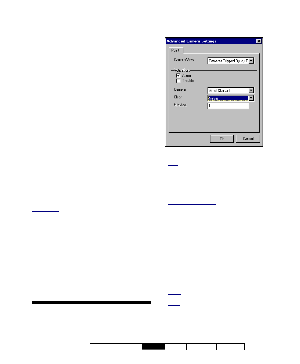
Step 3b: Set Up Event-Triggered Camera-Views
Doors and sensors on maps can be associated
with a 'camer a-view' to trigger a camera when
selected events occur at t he device (access
denied, sensor tripped, etc.).
Notes: This feature pertains to individual 'views' (i.e.,
the map and 'camera-views' must be on the same
'View', and the camera images will be visible only when
that 'view' is displayed. Conversely, "Advanced
Camera Settings" (camera-view assignments) on a
specific map will apply to ALL 'views' that contain the
same map, though the camera(s) will be visible only for
'views' that contain the target 'camera-view'.
Panel Firmware
version 4.15 or 4.2 (where available) or newer.
: This feature requires panel firmware
Overview of Steps:
• Define maps (1a), cameras (1b), and
camera-views (1c).
• Define view(s) and arrange the desired
maps, cameras, and/or 'camera-views'
therein (2).
• Place items such as doors and sensors
(input points) onto the maps (3a).
• Set "Advanced Camera Settings" for each
device that is to trigger a camera (to follow).
Topic Locator:
MyTools Bar
: Customize Maps, and (login
with a user name & ID if needed).
In the Tree
: Click your site/account button in
the tree, open Control & Status, and Panel
Control & Status (click the "+"), and login with
your user
ID and PIN if prompted for this.
Then, select: "Visual Director" (click the "+"),
ÖCustomize Maps.
Multi-Account Systems: First select [Account
Folders] in the 'tree', and double-click the desired
account.
Then, right-click the item (door or sensor), and
select Advanced Came ra Settings from the
pop-up menu.
Now, refer to the details for this screen w hile
viewing or changing settings as desired.
- Camera View: A previously-defined placeholder
that determines where the camera image will
appear. (Each camera-view shows the lasttriggered camera associated with it.)
Exception: Camera-views close when you select a
21-0381E v4.7.3
Welcome Report
Control Admin S ys Config Tech-Ref
Visual Director ÖCustomize Maps
Ö(right-click an item)
ÖAdvanced Camera Settings
different 'view', or move to a different screen/topic.
Note
: For a camera-image that cannot be overwritten
by another one, use : • A fixed camera (step 2); • A
link to a fixed camera (step 3a), or; • Set up a
'camera-view' that will not be used with any other
cameras (steps 1c & 3b).
On This Form
Door with two Readers: The following sections are
available separately for each reader.
- Activation: Select the states/conditions that you
wish to trigger the camera (e.g., alarm, trouble,
access denied, etc.);
Alarm: Forced entry, door held open too long, etc.
Trouble
: Door sensor circuit problems (e.g., cut or
shorted wiring).
- Camera: Select the camera that is to be
displayed when the selected event(s) occur at
the specific door or sensor;
- Clear: Whether or not the camera image is to be
closed/cleared automatically after a certain
period of time;
Never: The camera image will be left in place (until
you select a different view, or select some other task).
Timer
: The camera image will remain only for the
number of minutes that you select below (or until you
select a different view, etc.).
- Minutes: With "Clear" set as "Timer", enter the
number of minutes here (1 – 1440).
Tip: 1440 minutes is one day (24 hours).
75
Page 84

Checking Status & Controlling Items
Introduction to Status & Control
The Status and Control Feature
VEREX Director can monitor the status of most
system, area, and device a spects, and al lows
controlling the system on an area-by-area
basis, or for individual doors or input points.
Also See (≥ V4.0):
+ Visual Status and Control (Maps and Cameras)
+ To Connect: "New Installation? Try the Wizard
The status for individual ite ms at specific site
can be checked manually, as desired. As well,
the status toolbar allow s m onitoring a de sired
account for various items (sirens, fire alarms,
other alarms, and trouble conditions), and
provides a q uick way to v iew the details for
each item.
Items to be available under Control & Status depend on
the authorities associated with the user
entered when logging into "Control & Status". If you
were not asked to enter a user ID and PIN, then one
has been set up for automatic entry in your operator
settings. For details, refer to the section on
"Operators".
Status monitoring (either manually, or through the
status toolbar), requires that the VEREX Director
system be connected with the specific panel(s), and the
specific devices must be communicating.
If an item is listed as 'Off-Line', this typically indicates
either a communications problem, or a set-up error
(such as an incorrect module/POD serial number).
If all items on a screen are grey in colour, this generally
means that you are either not connected with the
specific panel, or the applicable module is 'off-line' (not
communicating).
Items changed through 'Control & Status' (such as
unlocking a door, or locking-out cards, etc.) remain in
effect until changed by another person or by a
scheduled Configuration setting.
ID and PIN
Connecting to the Associated Panel(s), An Overview:
1) See if you're already connected by
checking the status bar at the bottom
of the monitoring window.
Multi-Account systems: Ensure your desired
account is selected (click [Account Folders]
in the tree, and then double-click the specific
account).
2) If not connected, check to ensure the
communication software is running
on the specific PCs.
Detail: If the LCD/Telephone icon on the
Windows taskbar is black-and-white (colour =
running), start the communications service by
right-clicking the icon, and selecting "Start
Communications".
Related Topic
(Communications Manager)
: Serial Port / Modem Setup
3) Selec t Communications from your
MyTools bar, or
click
[Communications] in the 'tree', and
select Pending/OnLine.
4) Click the [+] at the bottom of the
form, or right-click the form, and
select Add New from the pop-up
menu. Then, select the desired
panel(s) (double-click to select), and
set "Action" to "Normal", and
"Frequency" to "Stay Connected" (9).
(Click OK when finished.)
5) Check that the connection is made, and
watch for the panel updates to occur.
(Click the 'Panel Group', and look for the status on
the right side of the screen.)
Note: Control & Status features will be available after
the panel updates have finished (look for a connection
state of 'Connected' and 'Idle State'.)
Also See (Related Topics):
+ "Panel Communications and Updates"
76 VEREX Director V4.73 User's Guide 21-0381E v4.7.3
Page 85

Accessing the Control and Status Topics for a Panel
See if you'r e already connected with the
panel(s) by checking the status bar at the
bottom of the monitoring window.
Multi-Account Systems: First select [Account
Folders] in the 'tree', and double-click the desired
account.
If not presently connected, initiate a connection
as described previously/above.
Then, access your desired topic:
Using the MyTools Bar: Select the desired Control
and Status topic from the MyTools bar (and login with
your user
Using the Tree: Click your site/account button in the
tree, open Control & Status, and Panel Control &
Status (click the "+"), and login with your user
PIN if prompted for this. Then, select your desired topic
in the 'tree' (under "Panel Control & Status").
If 'Panel-Groups' and 'Panels' are Listed Under Control
& Status: Select (open), your desired panel-group and
panel if these are listed in the 'tree'. Tip
Status" (and configuration) topics can be set to display
either as a single list, or on a panel-by-panel basis.
(To change the view: Right-click "Control & Status",
and select or deselect Logical Tree View). For more
information, refer to "Other Desktop Choices".
ID and PIN if prompted for this).
ID and
: "Control &
-------------------------
Use the Grid / Form toolbar-button to s elect
your preferred vie w-mode ( forms vi ew is
generally rec ommended for Control & Status
topics).
Then, refer to the topic as sociated with your
desired Control & Status topic.
Note: If the status window appears blank, or
unavailable (items are grey in colour), this means you
are not connected with the specific panel or account.
To initiate a connection, refer to "Connecting to the
Associated Panel(s), An Overview" (previous/above).
Automatic Login
automatically for a specific operator, refer to the section
on "Operators".
If "Cannot Log In to Control and Status due to a
Conflict" appears: This means the same data may
have been changed through the software and locally
through a keypad. When an operator with configuration
permissions accesses the 'configuration' topic for the
mentioned item, they will be prompted to correct the
conflict. For details, refer to "Correcting
Communication / Update Errors".
: To set the 'login' to occur
21-0381E v4.7.3
Welcome Report
Control Admin S ys Config Tech-Ref
77
Page 86

Using the Status Toolbar
The Status Toolbar
The status toolbar allows monitoring for
various items (sirens, fire alarms, other alarms,
and trouble c onditions), an d provides a quick
way to view the details for each item.
Multi-Account Systems: You can set the account to be
monitored by the status toolbar (when each operator is
logged in) by clicking [Monitor] on the far-right end of
the toolbar. This can also be set in the screen for each
operator. For details, refer to the section on
"Operators".
The status toolbar is active only when the system is
connected with the specific panel(s).
The status toolbar will remain active when the software
is in lockout mode (operator/keyboard lockout). This
allows continuous monitoring of an account while
blocking access to other features.
For details on the lockout feature, refer to "Exiting,
Logging Off, or Changing Operators".
Also See (≥ V4.0):
+ Visual Status and Control (Maps and Cameras)
+ To connect: "New Installation? Try the Wizard"
Using the Status Toolbar
See if you'r e already connected with the
panel(s) by checking the status bar at the
bottom of the monitoring window.
Multi-Account Systems: First select [Account
Folders] in the 'tree', and double-click the desired
account.
If not presently connected, initiate a connection
with the desired panel(s).
For details, refer to "Connecting to the Associated
Panel(s), An Overview" (under "Checking Status &
Controlling Items", previous).
Multi-Account systems
being monitored by the status toolbar, click the button
on the far-right end of the toolbar.
-------------------------
: To verify which account is
Then, refer to the selection-descriptions for this
screen w hile selecting a n item from the
toolbar.
If the software is presently in 'lockout' mode (with only
the status toolbar available), you'll be asked to login
with your operator name and password when you click
the toolbar.
Similarly, if you are not presently 'logged' into 'Control &
Status', you'll be asked to enter your user
ID and PIN.
The Status Toolbar
- Siren: This button is shown in colour (and with a
'siren' sound) if any inputs set to trigger a 'siren'
or 'sonalert' have been 'tripped' in an armed
area (unless the alarm has been silenced).
Clicking this button displays the Area status
screen, allowing you to identify the alarm(s)
quickly.
- Fire: This button is shown in colour if any "fire"
inputs have been 'tripped' (e.g., by a smoke, fire,
or CO detector). Clicking this button displays
the Area status screen, allowing you to quickly
identify the area(s) that may need to be
evacuated.
- Alarm: This button is shown in colour if any
input points (monitoring sensors) have been
'tripped' in an armed area. Clicking this button
displays the Area status screen, allowing you to
identify the alarm(s) quickly.
- Trouble: This button is shown in colour if any
'equipment' conditions are active (i.e., panel or
module in trouble). Clicking this button displays
the Equipment status screen, allowing you to
locate the problem(s) quickly. If the 'trouble'
button is flashing, this indicates that an ACfailure is in effect at the panel.
- Monitor: This allows selecting the account to
be monitored by the status toolbar (for the
operator who is presently logged in).
(If you change this, you can save your changes by
opening the V
and then S
The toolbar is active only when the VEREX Director
software is connected with the associated panel(s).
This does not
the monitoring window. (The monitoring window
pertains to the account that is selected (doubleclicked) in the 'tree.)
iew menu, selecting Desktop Settings,
ave).
effect the account to be monitored in
78 VEREX Director V4.73 User's Guide 21-0381E v4.7.3
Page 87
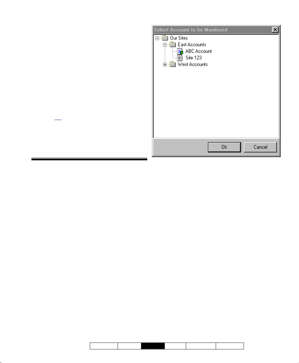
Selecting the Account to be Monitored by the Status Toolbar
For systems with multiple accounts, you can
set the account to be monitored by the status
toolbar (for each operator who is logged in):
Click Monitor on the far-right end of the
toolbar (or op en the View menu, and select
Change Mon itor Account ). Then, select
your desired account, and click OK.
When finish ed, save y our changes by
opening the View menu, selecting Desktop
Settings, and then Save.
This does not effect the account to be monitored in
the monitoring window. (The monitoring window
pertains to the account that is selected (doubleclicked) in the 'tree.)
The status toolbar is active only when the VEREX
Director software is connected with the associated
panel(s).
Monitor (from the Status Toolbar)
(Account Folders and Accounts)
- The account to be monitored by the status
toolbar (identified with a small green square).
Select the desired account, and click OK.
21-0381E v4.7.3
Welcome Report
Control Admin S ys Config Tech-Ref
79
Page 88

Miscellaneous Status Tasks
Panel Date and Time
VEREX Director lets you c heck the d ate and
time stored at a system panel, compare it w ith
that at the host compute r, and adjust the
panel's date / time to match the computer, if
necessary.
Initiate a Connection, and Access this Topic
See if you'r e already connected with the
panel(s) by checking the status bar at the
bottom of the monitoring window.
Multi-Account Systems: First select [Account
Folders] in the 'tree', and double-click the desired
account.
If not presently connected, initiate a connection
with the desired panel(s).
For details, refer to "Connecting to the Associated
Panel(s), An Overview" (under "Checking Status &
Controlling Items", previous).
-------------------------
Then, select Control & Status - Sy stem from
the MyTools bar, or
Control & Status in the 'tree'.
Using the Tree: Click your site/account button in the
tree, and open Control & Status, and Panel Control &
Status (click the "+" beside each topic).
Login with your user ID and PIN if prompted for
this.
Panel Groups and Panels: Open your specific panel
group and panel if these are listed in the 'tree'. Tip
The 'tree' can be set to show Control & Status topics in
a single list (logical tree view), or on a panel-by-panel
basis. For details, refer to "Other Desktop Choices".
If the status screen is blank or inactive (or if you'd like
more information), refer to "Accessing the Control and
Status Topics for a Panel" (under "Checking Status &
Controlling Items", previous).
When the sc reen appears, use the Grid /
Form toolb ar-button to select your pref erred
view-mode
Multi-Panel Systems: Select the desired panel at the
bottom of the form (if not shown/selected in the 'tree').
(forms view is recommended here).
sel ect System under
:
Checking or Changing the Date / Time
To 'read' the date and ti me from the panel,
click [Get Panel Tim e]. Then, check the
'difference' va lue to see if t he panel date and
time need to be changed.
If you need t o set the dat e and time a t th e
panel to match the VEREX Director computer,
click [Set Panel Time with Server Time].
80 VEREX Director V4.73 User's Guide 21-0381E v4.7.3
Page 89
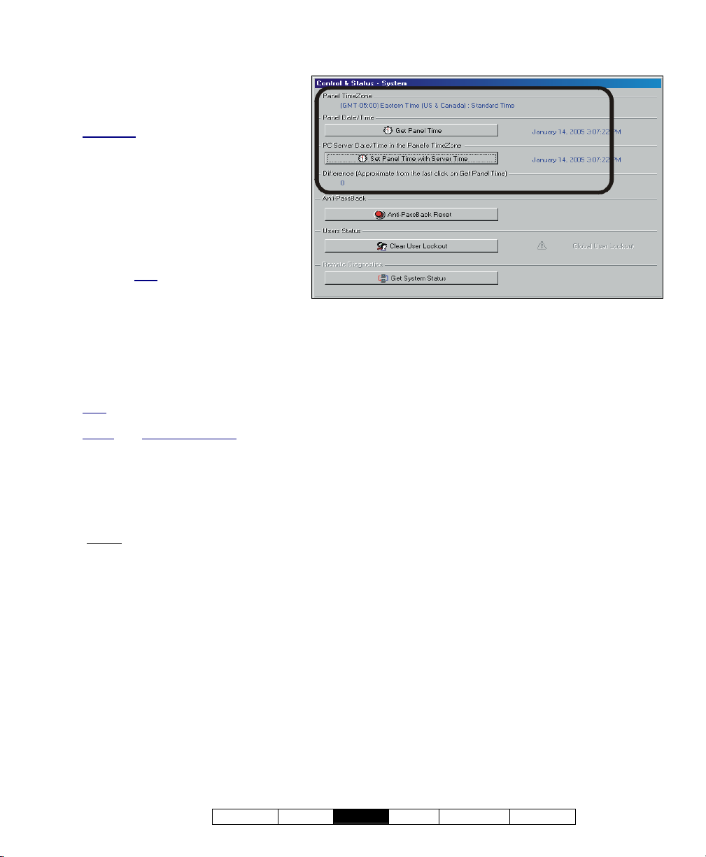
Control & Status ÖPanel Control & Status
ÖSystem (Date/Time Portion)
-Panel (bottom of the form): This is
where you select a desired panel (for
systems with more than one).
Alternative: You can also set the 'tree' to
list status topics on a panel-by-panel basis.
For details, refer to "Other Desktop
Choices".
- Panel Time Zone: This shows the
'time zone' for the specific panel. If
different from the PC/server time
zone, any clock updates will be
adjusted accordingly.
This will be different from the PC/server
time zone only
via modem or wide area network. The
panel time zone is set through the panelgroup screen. For details, refer to "Panel
Groups and Connection Settings".
for remote panels managed
- [Get Panel Time]: Reads the date and time
setting at the panel.
- [Set Panel Time with Server Time]: Changes
the time at the panel to match the computer.
Note: In multi-PC (client-server) systems, the panel
time is synchronized with that of the VEREX Director
server
PC. Director-Server PC: This is the PC that
includes "...Director-Server.exe", and typically
contains the database as well.
- Panel Date / Time: The present date & time
setting at the panel.
- PC Server Date / Time: The present date &
time setting at the VEREX Director computer
(server
if applicable).
- Difference (Approximate): The approximate
time-difference between the panel and the
computer.
If necessary, you can set the date and time for the
computer through the windows 'Control Panel' (select
Start, Settings, Control Panel, and Date/Time).
When finished, be sure to synchronize the panel clock
(i.e., "Set Panel Time...").
21-0381E v4.7.3
Welcome Report
Control Admin S ys Config Tech-Ref
81
Page 90

Resetting Users' Antipassback Status
Antipassback (APB): A feature that blocks individual
cards from being used to:
+ Re-enter the same area, or;
+ Re-enter the facility from 'outside', and/or;
+ (Optional): Enter other areas;
…Unless
person must use their card/token at every reader they
encounter (that is set to "Detect Antipassback"). Tip:
This helps to protect against unauthorized card usage.
Enabling the Antipassback Feature
antipassback tracking for specific areas and doors,
refer to the "Antipassback" selections under "Areas and
Related Settings", and the "Detect Antipassback"
selection under "Reader 1 & 2 Settings for a Door".
they are recorded as exiting first--i.e., each
: To enable
Antipassback Reset
From time-to-time, a person may be unable to
enter a door due to an ant ipassback vio lation
(such as if th ey entered or e xited when th e
system unlocked a door for someone else).
This can b e corrected by resettin g th e
antipassback status for the specific user, or all
users, as desired.
Reset APB Status by Area: You can also reset user
antipassback status on an area-by-area basis. For
details, refer to "Checking Status or Controlling Items
by Area" (in a following section).
Resetting Antipassback Status
Initiate a connection with the panel(s), and
access the "System" Control & Status topic as
described previously/above.
Multi-Panel Systems: Select the desired panel at the
bottom of the form (if not shown/selected in the 'tree').
If the status screen is blank or inactive (or if you'd like
more information), refer to "Accessing the Control and
Status Topics for a Panel" (under "Checking Status &
Controlling Items", previous).
Then, click [Anti-Passback Reset] . In the
next screen, select an ind ividual user, o r "All
Users", and the panel(s) to be affected b y the
reset (i.e., t he ones as sociated with the
specific areas and doors).
When finishe d, click OK, and respond to any
additional messages that appear.
82 VEREX Director V4.73 User's Guide 21-0381E v4.7.3
Page 91
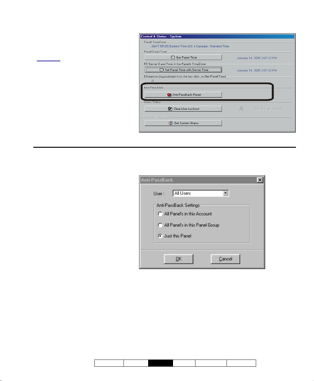
Control & Status ÖPanel Control & Status
ÖSystem (Antipassback)
-Panel (bottom of the form): This is
where you select a desired panel (for
systems with more than one).
Alternative: You can also set the 'tree' to
list status topics on a panel-by-panel basis.
For details, refer to "Other Desktop
Choices".
Anti-Passback
- [Anti-Passback Reset]: This opens a
small screen that allows resetting the
antipassback status for a single user,
or all users for doors associated with
selected panel(s).
Control & Status ÖPanel Control & Status
ÖSystem Ö[Anti-Passback Reset]
-User: This allows selecting a specific
user, or "All Users" to have their
antipassback status reset at the
selected panel(s).
Anti-Passback Settings
These choices allow you to select the panels
associated with the user APB status-reset
(for systems that have more than one panel).
(If you have only one panel, these settings
all have the same effect.)
- All Panels in this Account: This will
reset the antipassback status for all
panels in your presently-selected
account.
- All Panels in this Panel Group: This
will reset the antipassback status for
your selected panel, plus any others that
communicate through the same cable or remote
modem.
- Just this Panel: This will reset the antipassback
status for your selected panel only.
21-0381E v4.7.3
Welcome Report
Control Admin S ys Config Tech-Ref
83
Page 92

Clearing a "Bad Card/PIN Global Lockout"
Global User Lockouts
The 'Bad Card/PIN' trackin g feature helps to
prevent unauthorized persons 'hacking ' t heir
way into a co ntrolled area. All users ca n be
locked out automatically if a lot of invalid cards
and/or PINs are detected during a set time.
Related: • Account Information ÖBad Card/PIN;
• Configuration ÖAreas ÖAccess Ö"Bad Card
Action"
The [Clear User Lockout] button allo ws
clearing the lockout, so all authorized persons
can enter as usual.
Clearing a Global User Lockout
Initiate a connection with the panel(s), and
access the "System" Control & Status topic as
described previously/above.
Multi-Panel Systems: Select the desired panel at the
bottom of the form (if not shown/selected in the 'tree').
If the status screen is blank or inactive (or if you'd like
more information), refer to "Accessing the Control and
Status Topics for a Panel" (under "Checking Status &
Controlling Items", previous).
Then, click [Clear Use r Lockout] , and watch
for the status indicator to change.
84 VEREX Director V4.73 User's Guide 21-0381E v4.7.3
Page 93
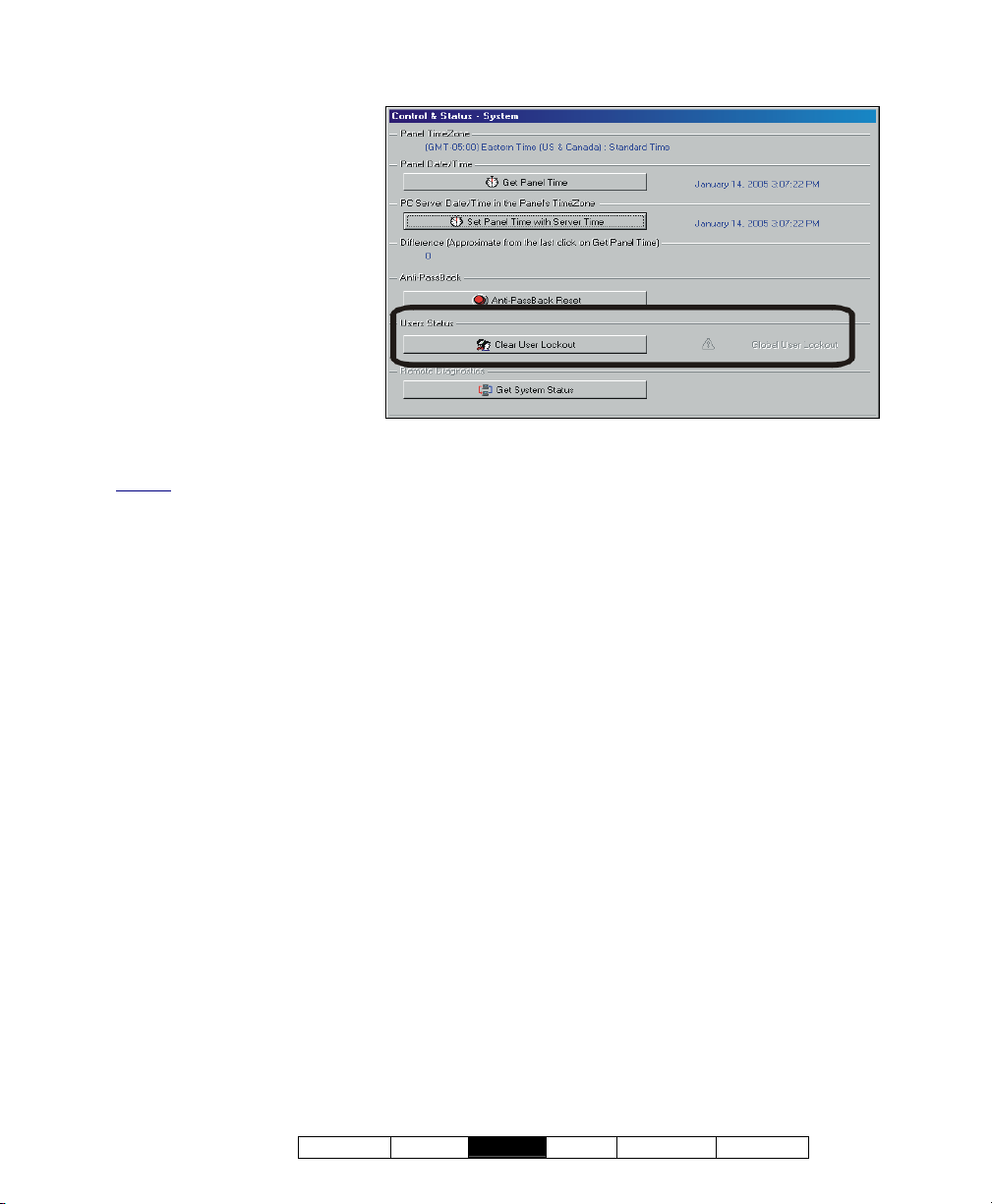
Control & Status ÖPanel Control & Status
ÖSystem Ö[Clear User Lockout]
- Panel (bottom of the form):
This is where you select a
desired panel (for systems with
more than one).
Alternative: You can also set the
'tree' to list status topics on a panelby-panel basis. For details, refer to
"Other Desktop Choices".
User Status
- [Clear User Lockout]: This
allows resetting a "Global User
Lockout" triggered by the 'Bad
Card/PIN' tacking feature.
- Global User Lockout: This
shows whether or not a 'Global
User Lockout' is presently in
effect.
Related: • Account Information ÖBad Card/PIN
21-0381E v4.7.3
Welcome Report
Control Admin S ys Config Tech-Ref
85
Page 94
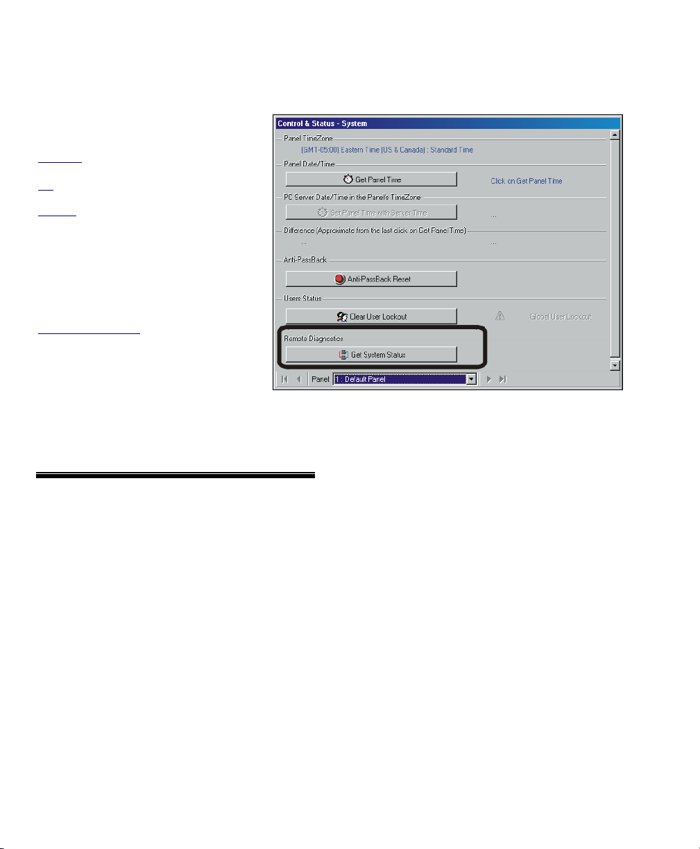
Checking System Status (Remote Diagnostics)
Remote Diagnostics
This feature a llows you to check the
Control & Status ÖPanel Control & Status
ÖSystem ("Get System Status" portion)
status of a n umber of hardw are and
communications aspects of a panel.
Attention: This feature is supported for xL
panels only (narrow rectangular mainboard).
Tip
: You can also run reports based on
previous status/diagnostic sessions.
Related
: ÖReports, ÖPanel Diagnostic
Reporting on Panel Diagnostics
Running Remote Diagnostics
Initiate a connection with the panel(s),
and access t he " System" Control &
Status top ic as described
previously/above.
Multi-Panel Systems: Select the desired
panel at the bottom of the form (if not
shown/selected in the 'tree').
If the status screen is blank or inactive (or if
you'd like more information), refer to
"Accessing the Control and Status Topics for
a Panel" (<<).
Then, click [Get Sy stem Status], and watch
for a small screen to appear showing status
details.
- Panel (bottom of the form): This is where you
select a desired panel (for systems with more
than one).
Tip: "Control & Status" (and configuration) topics can
be set to display either as a single list, or on a panelby-panel basis. (To change the view: Right-click
"Control & Status", and select or deselect Logical Tree
View). For more information, refer to "Other Desktop
Choices".
Remote Diagnostics
- [Get System Status]: This shows a progress
bar while collecting data, and then opens a
small screen showing various status items for
the specific panel.
86 VEREX Director V4.73 User's Guide 21-0381E v4.7.3
Page 95
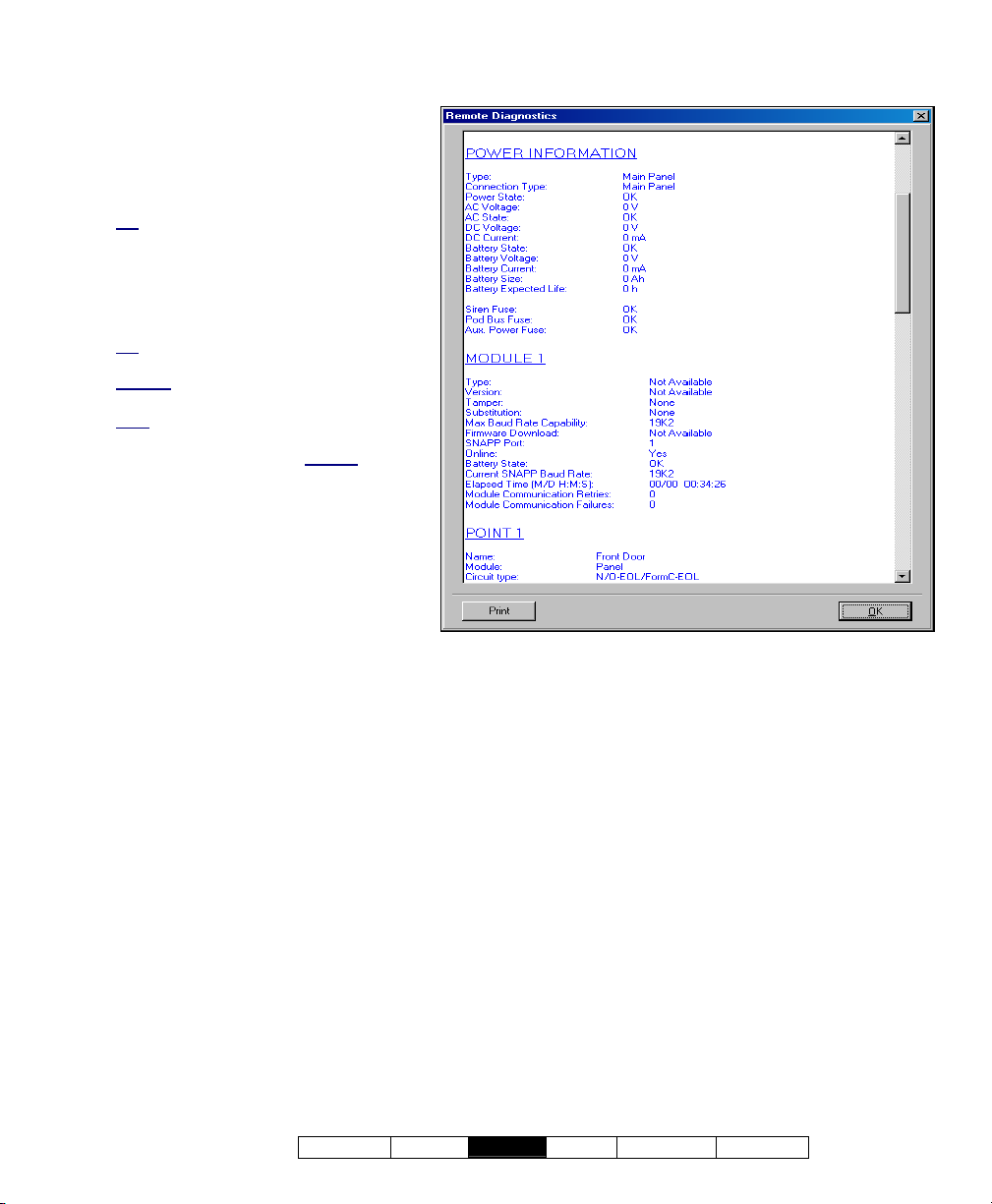
- On This Screen: This shows various
physical status aspects for the specific
panel.
- [Print]: This allows printing the onscreen diagnostic data.
Tip: A print-setup screen will appear—
allowing you to select a printer, and set up
the print-job as desired.
- [OK]: This saves the on-screen data
(internally), and closes the Remote
Diagnostics screen.
Tip: You can also run reports based on
previous status/diagnostic sessions.
Related
: ÖReports, ÖPanel Diagnostic
Reporting on Panel Diagnostics
Note
: The Director software retains 24
months worth of diagnostics sessions, or
the last 100—whichever is greater
.
Control & Status ÖPanel Control & Status
ÖSystem Ö[Get System Status]
21-0381E v4.7.3
Welcome Report
Control Admin S ys Config Tech-Ref
87
Page 96

Checking the Status of Panels (Equipment)
Panel Status (Equipment)
Conditions Monitored for Each Panel
Various con ditions (such as lo w ba ttery,
tampering, etc.) can be monitored for each
panel. This helps to main tain the integrity of
each system panel.
Also See: Control & Status, ÖPanel Control & Status,
ÖSystem, ÖPower
Checking Power Levels
Items to be Monitored
monitored for a panel, refer to "Equipment Settings
(Pseudo / Internal Inputs)".
: To set the conditions to be
Initiate a Connection, and Access this Topic
See if you'r e already connected with the
panel(s) by checking the status bar at the
bottom of the monitoring window.
Multi-Account Systems: First select [Account
Folders] in the 'tree', and double-click the desired
account.
If not presently connected, initiate a connection
with the desired panel(s).
For details, refer to "Connecting to the Associated
Panel(s), An Overview" (under "Checking Status &
Controlling Items", previous).
-------------------------
Then, select Control & S tatus - E quipment
from the MyTools bar, or
select Equipment
under "Control & Status: System" in the 'tree'.
Using the Tree: Click your site/account button in the
tree, and open Control & Status, Panel Control &
Status, and System (click the "+" beside each topic).
Alternative
toolbar.
: You can also click Trouble on the status
Login with your user ID and PIN if prompted for
this.
Panel Groups and Panels: Open your specific panel
group and panel if these are listed in the 'tree'. Tip
The 'tree' can be set to show Control & Status topics in
a single list (logical tree view), or on a panel-by-panel
basis. For details, refer to "Other Desktop Choices".
If the status screen is blank or inactive (or if you'd like
more information), refer to "Accessing the Control and
Status Topics for a Panel" (under "Checking Status &
Controlling Items", previous).
:
Working with This Screen
When the status screen appears, use the Grid
/ Form toolbar-button to sel ect your prefe rred
view-mode.
Forms view: All equipment topics on a graphical
screen;
Grid View
Multi-Panel Systems
bottom of the form (if not shown/selected in the 'tree').
: A list of monitored equipment topics.
: Select the desired panel at the
Then, refer to the selection-descriptions for this
screen w hile vie wing the available st atus
information.
Tip: Any alarm conditions that are in effect will be
shown in colour. Be sure to dispatch someone to
deal with any conditions that require attention.
Individual items that are grey in colour are not presently
being monitored by the system.
To block the monitoring of a specific condition:
Go to "ConfigurationÖSystemÖEquipment" for the
specific panel, and set the "Preprocess" for the desired
item to "Undefined". For details, refer to "Equipment
Settings (Pseudo/Internal Inputs)".
88 VEREX Director V4.73 User's Guide 21-0381E v4.7.3
Page 97
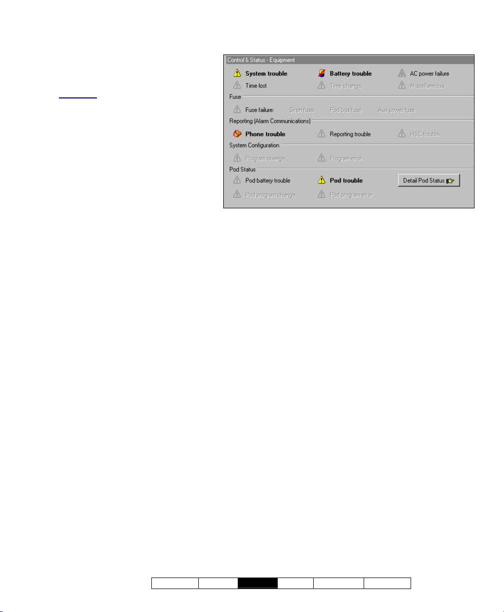
Control & Status ÖPanel Control & Status
ÖSystem ÖEquipment
-Panel (bottom of the form): This is
where you select a desired panel (for
systems with more than one).
Alternative: You can also set the 'tree' to
list status topics on a panel-by-panel basis.
For details, refer to "Other Desktop
Choices".
- (top of screen): Status of various
items pertaining to a specific account
or site.
- Fuse: Whether any of the fuses on
this system panel has failed.
- Reporting (Alarm
Communications): Status of
communications links (phone and
high-security HSC line), and whether
or not this has affected an alarm transmission.
- System Configuration: Panel programming
issues/errors.
- Module Status: Items pertaining to an
expansion module (door controller, point
expansion module, etc.).
- [Detail Module Status]: Jumps to the
module/POD status window (grid-view), so you
can quickly locate the device that is in trouble.
21-0381E v4.7.3
Welcome Report
Control Admin S ys Config Tech-Ref
89
Page 98

Checking Power Levels (≥V4.4)
System Power Status
The pow er status screen a llows you t o check
the status of v arious items pertaining to mains
input voltage, battery life remaining, etc.
Note: Some features are supported only by xL panels.
Unsupported items will be shown as zero (0).
Also See: Control & Status, ÖPanel Control & Status,
ÖSystem, ÖEquipment
Checking the Status of Panels (Equipment)
Initiate a Connection, and Access this Topic
See if you'r e already connected with the
panel(s) by checking the status bar at the
bottom of the monitoring window.
Multi-Account Systems: First select [Account
Folders] in the 'tree', and double-click the desired
account.
If not presently connected, initiate a connection
with the desired panel(s).
For details, refer to "Connecting to the Associated
Panel(s), An Overview" (<<).
-------------------------
Then, select Control & Status - P ower from
the MyTools bar, or
sel ect Power under
"Control & Status: System" in the 'tree'.
Using the Tree: Click your site/account button in the
tree, and open Control & Status, Panel Control &
Status, and System (click the "+" beside each topic).
Login with your user ID and PIN if prompted for
this.
Panel Groups and Panels: Open your specific panel
group and panel if these are listed in the 'tree'. Tip:
"Control & Status" (and configuration) topics can be set
to display either as a single list, or on a panel-by-panel
basis.
(To change the view: Right-click "Control & Status",
and select or deselect Logical Tree View). For more
information, refer to "Other Desktop Choices".
If the status screen is blank or inactive (or if you'd like
more information), refer to "Accessing the Control and
Status Topics for a Panel" (<<).
Working with This Screen
When the sta tus screen appears, use scroll
bar at the bottom to view all items listed.
Form/Grid Views: This screen uses a custom grid view,
and the Form/Grid button will be disabled.
Multi-Panel Systems
bottom of the form (if not shown/selected in the 'tree').
: Select the desired panel at the
Then, refer to the selection-descriptions for this
screen w hile vie wing the available st atus
information.
Tip: Be sure to dispatch someone to deal with any
conditions that require attention.
90 VEREX Director V4.73 User's Guide 21-0381E v4.7.3
Page 99
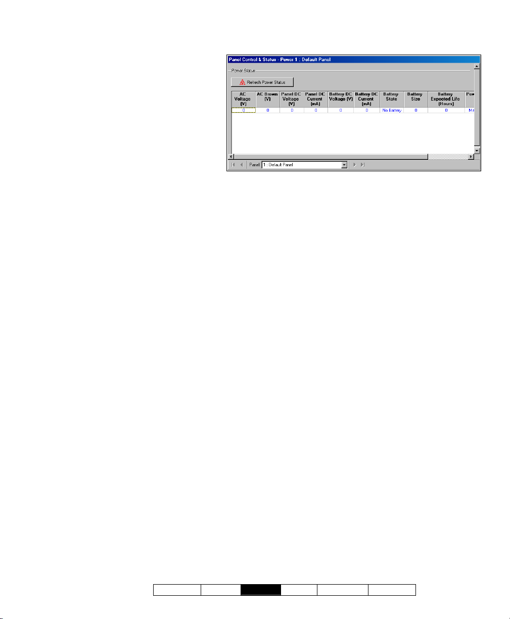
-Panel (bottom of the form): This is
where you select a desired panel (for
systems with more than one).
Tip: "Control & Status" (and configuration)
topics can be set to display either as a
single list, or on a panel-by-panel basis.
(To change the view: Right-click "Control &
Status", and select or deselect Logical Tree
View). For more information, refer to
"Other Desktop Choices".
Control & Status ÖPanel Control & Status
ÖSystem ÖPower
On This Screen
Power Status
- [Refresh Power Status]: Click this to refresh
the data onscreen.
- (Columns of Data): This screen shows the
status of various items pertaining to mains input
voltage, battery life remaining, etc.
Note: Some features are supported only by xL panels.
Unsupported items will be shown as zero (0).
21-0381E v4.7.3
Welcome Report
Control Admin S ys Config Tech-Ref
91
Page 100

Checking the Status of Modules
Module Status
The module status screen s hows the status of
various items pertaining to each s ystem
module (keypad, door controller, etc.).
Also See (Related Topics):
+ Checking the Status of Panels (Equipment)
+ Checking Power Levels
Initiate a Connection, and Access this Topic
See if you'r e already connected with the
panel(s) by checking the status bar at the
bottom of the monitoring window.
Multi-Account Systems: First select [Account
Folders] in the 'tree', and double-click the desired
account.
If not presently connected, initiate a connection
with the desired panel(s).
For details, refer to "Connecting to the Associated
Panel(s), An Overview" (under "Checking Status &
Controlling Items", previous).
-------------------------
Then, select Control & Status - Modules from
the MyTools bar, or
'tree' under "Control & Status: System:
Equipment".
Using the Tree: Click your site/account button in the
tree, and then open these branches by clicking the "+"
beside each topic: • Control & Status, • Panel
Control & Status, • System, • Equipment.
Alternative
Status] in the equipment status screen.
: You can also select [Detail Module
Login with your user ID and PIN if prompted for
this.
Panel Groups and Panels: Open your specific panel
group and panel if these are listed in the 'tree'. Tip
The 'tree' can be set to show Control & Status topics in
a single list (logical tree view), or on a panel-by-panel
basis. For details, refer to "Other Desktop Choices".
If the status screen is blank or inactive (or if you'd like
more information), refer to "Accessing the Control and
Status Topics for a Panel" (under "Checking Status &
Controlling Items", previous).
select Modules in the
:
Working with This Screen
Use the Grid / Form toolbar-button to s elect
your preferred view-mode.
Forms view: Details for one module at a time;
Grid View
: All modules in a list.
Select a desired module in the list.
Tip: In 'forms' view, you can select a module at the
bottom of the form, or use the 'Find' and 'Find Next'
buttons (binoculars) to search by name (or 1
characters--e.g., nam∗
).
st
few
Then, refer to the selection-descriptions for this
screen w hile vie wing the available st atus
information.
Tip: Any alarm conditions that are in effect will be
shown in colour. Be sure to dispatch someone to deal
with any conditions that require attention.
92 VEREX Director V4.73 User's Guide 21-0381E v4.7.3
 Loading...