

VERDER Verderflex Vantage 5000 Series Original Operating Manual

Peristaltic Cased Tube Pump
Original Operating Manual Vantage 5000
Version 1.4v-09/2019
Print-No. 01

Version 1.4v-09/2019
Print-No. 01
Vantage 5000
The information in this document is essential for the safe operation and servicing of Verderex
Vantage 5000 family of pumps. This document must be read and understood thoroughly prior to
installation of unit, electrical connection and commissioning.
Vantage 5000 1.4v-09.2019 2 | Page
®

Table of Contents
1 About this Document
1.1 Target Groups
1.2 Warnings and Symbols used in the Manual
1.3 Warnings and Symbols used on the Pump
2 Safety
2.1 Intended Use
2.2 General Safety Instructions
2.2.1 Product Safety
2.2.2 Obligation of the Operating Company
2.3 Specic Hazards
2.3.1 Hazardous Pumped Liquids
3 Transport, Storage and Disposal
3.1 Transport
3.1.1 Unpacking and Inspection on Delivery
3.1.2 Lifting
3.2 Storage Conditions
3.3 Interim Storage After Using the Pump
3.4 Interim Storage Before Using the Pump
3.5 Disposal
4 Layout and Function
4.1 Design Details of Vantage 5000
4.2 Vantage 5000 - an overview
4.3 Layout
4.3.1 Vantage 5000 Exploded View - Continuous
Tube
4.3.2 Vantage 5000 Exploded View - Tube
Element
5 Installation and Connection
5.1 Electrical Installation
5.1.1 Preparing for Installation
5.1.1.1 Checking the Ambient Conditions
5.1.2 Connecting to a Power Supply
5.1.3 Protective Earthing/Grounding
5.1.4 Electrical Isolation
5.2 Installing the Tube
5.2.1 Vantage 5000 - Tube Options
5.2.2 Installing the Continuous Tube
5.2.3 Installing the Tube Element
6 User Interface - an overview
7.7 Users / Passcodes
7.7.1 Users / Passcodes - an Overview
7.7.2 Users / Passcodes Setup
7.7.3 Passcode Request ON
7.7.4 Users/Passcodes
7.8 Remote Control
7.9. Logs / History
8 Operational Modes
8.1 Flow Mode
8.1.1 Select the Flow Mode
8.2 Batch Mode
8.2.1 Select the Batch Mode
8.3 Dose Mode
8.3.1 Select the Dose Mode
8.3.2 Memory Dose
9 Vantage 5000 Software Update Process
10 System Reset Procedure
11 Vantage 5000 Screen Calibration
12 Inspections, Maintenance and Repairs
12.1 Inspections
12.2 Maintenance
12.2.1 Cleaning the Pump Head
12.2.2 Maintenance Schedule
12.3 Repairs
12.3.1 Returning the Pump to the Service Centre
12.4 Ordering Spare Parts
13 Troubleshooting
13.1 Pump malfunctions
14 List of Figures and Tables
14.1 List of Figures
14.2 List of Tables
15 Declaration of Conformity
16 Declaration of Incorporation
7 Screen Layout
7.1 Home Screen
7.2 Main Menu
7.3 Job Files
7.4 Edit Job Files
7.4.1 Delivery Setup
7.4.2 Pump Setup
7.4.3 Mode Setup (Batch/Dose Mode)
7.4.4 Real Time Clock Mode (RTC) Setup
7.4.5 Log Setup
7.5 Calibration
7.5.1 Calibration Procedure
7.6 Settings
7.6.1 General
7.6.2 Outputs
Vantage 5000 1.4v-09.2019 3 | Page

Table of Contents (continued)
1 Appendix A
Pump Specication
2 Appendix B
Spare Parts Replacement
3 Appendix C
Ordering Information
4 Appendix D
Analogue Remote Control Options
5 Appendix E
25 WAY Remote I/O Connector
6 Appendix F
Breakout Box
7 Appendix G
Error Codes and Description
8 Appendix H
Formatting the USB drive
9 Appendix I
Standards
10 Appendix J
Modbus® RTU
Vantage 5000 1.4v-09.2019 4 | Page
1 About this Document
The Verderex Vantage 5000 range of peristaltic pumps have been developed according to the latest technology and subject to
continuous quality control. These operating instructions are intended to facilitate familiarisation with the pump and its designed
use. This manual will act as a guide for operating the pump. You are advised to follow these guidelines to operate the pump correctly. These operating instructions do not take local regulations into account; the operator must ensure that such regulations are
strictly observed by all, including the personnel responsible for installation.
1.1 Target Groups
Target Groups Duty
Operating Company
Qualied personnel, tter u Read, observe and follow this manual and the other applicable
Table 1 Target Groups
u Keep this manual available at the operating site of the pump.
u Ensure that personnel read and follow the instructions in this
manual and any other applicable documents, especially all safety
instructions and warnings.
u Observe any additional rules and regulations referring to the system.
documents, especially all safety instructions and warnings.
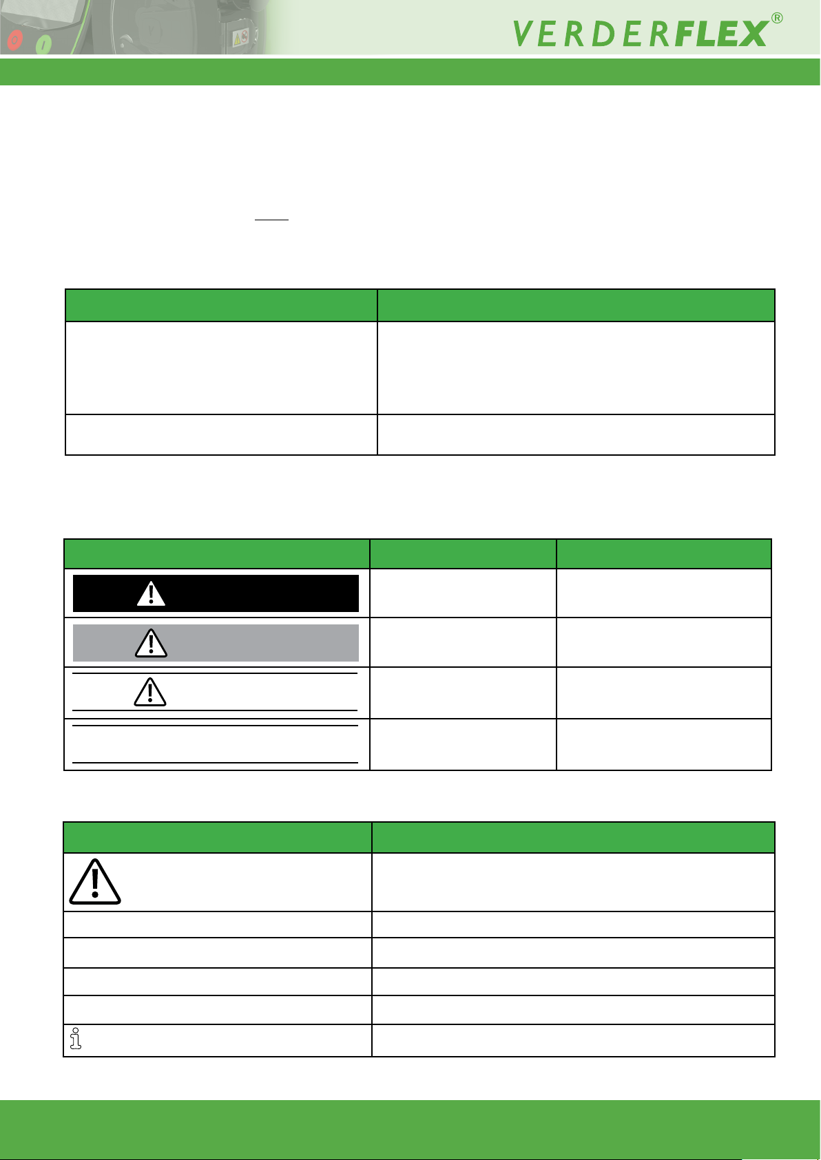
1.2 Warnings and Symbols Used in the Manual
Warning Risk Level Consequences of disregard
DANGER
WARNING
CAUTION
Immediate risk Death, serious bodily harm
Potential acute risk Death, serious bodily harm
Potential hazardous situation Potential damage to the pump
Note
Table 2 Warnings Used in the Manual
For information
Possible incorrect use / maintenance
of pump
Symbol Meaning
Safety warning sign in accordance with DIN 4844 - W9
u Take note of all information highlighted by the safety warning sign
and follow the instructions to avoid injury or death.
u
1., 2., Multiple-step instructions
p
g
Table 3 Symbols Used in the Manual
Vantage 5000 1.4v-09.2019 5 | Page
Instruction
Precondition
Cross-reference
Information
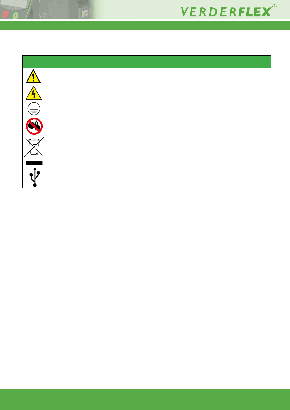
1.3 Warnings and Symbols Used on the Pump
Warnings and Symbols Meaning
Safety Warning
Warning of Dangerous Electrical Voltage
Protective Earth (Ground)
Pinch Point/Entanglement Hazard
Waste Electronic and Electrical Equipment (WEEE)
USB 2.0
Table 4 Warning and Symbols Used on the Pump
Vantage 5000 1.4v-09.2019 6 | Page

2 Safety
2.2.2 Obligation of the Operating Company
The manufacturer does not accept any liability for damage
resulting from disregard of this documentation.
2.1 Intended Use
u Only use the pump to handle uids compatible with the
tted tube (g Appendix A)
u Adhere to the operating limits
u Consult the manufacturer regarding any other use of the
pump.
Prevention of misuse (examples)
u Note the operating limits of the pump with regard to
temperature, pressure, ow rate and motor speed
(g Appendix A)
u Do not operate the pump with any inlet/outlet valves closed
u
Only install the pump as recommended in this manual.
For example, the following are not allowed:
– Running the pump with tube that is not compatible
with the tted rotor
– Insert any items into contact with moving parts
– Installation in the immediate vicinity of extreme hot or
cold sources (g Appendix A)
– Running pump in explosive atmosphere
2.2 General Safety Instructions
Observe the following instructions before carrying out any
work.
2.2.1 Product Safety
• These operating instructions contain fundamental infor-
mation which must be complied with during installation,
operation and maintenance. Therefore this o p e ra t in g
manu a l m us t be re a d a n d understood both by the
installing personnel and the responsible trained personnel
/ operators prior to installation and commissioning, and it
must always be kept easily accessible within the operating
premises of the machine.
Not only must the general safety instructions laid down
in this chapter on “Safety” be complied with, but also the
safety instructions outlined under specic headings.
• Operate the pump only if it and all associated systems are
in good functional condition.
• Only use the pump as intended, be fully aware of safety
and risk factors involved and the instructions in this
manual.
• Keep this manual and all other applicable documents
complete, legible and accessible to personnel at all times.
• Refrain from any procedure or action that would pose a
risk to personnel or third parties.
• In the event of any safety-relevant faults, shut down the
pump immediately and have the malfunction corrected by
qualied personnel.
• The installation of the pump must comply with the require-
ments of installation given in this manual and any local,
national or regional health and safety regulations.
Safety-conscious operation
• Ensure that the following safety aspects are
observed and monitored:
– Adherence to intended use
– Statutory or other safety and accident-prevention
regulations
– Safety regulations governing the handling of
hazardous substances if applicable
– Applicable standards and guidelines in the country
where the pump is operated
• Make personal protective equipment available
pertinent to operation of the pump.
Qualied personnel
• Ensure that all personnel tasked with work on the pump
have read and understood this manual and all other
applicable documents, including the safety,
maintenance and repair information, prior to use or
installation of the pump.
• Organize responsibilities, areas of competence and
the supervision of personnel.
• Have all work carried out by specialist technicians
only.
• Ensure that trainee personnel are under the
supervision of specialist technicians at all times when
working with the pump.
Warranty
The warranty is void if the customer fails to follow any
Instruction, Warning or Caution in this document. Verder
has made every effort to illustrate and describe the product in this document. Such illustrations and descriptions
are however, for the sole purpose of identication and do
not express or imply a warranty that the products are mer-
chantable or t for a particular purpose, or that the products will necessarily conform to the illustration or descriptions.
Obtain the manufacturer’s approval prior to carrying out
any modications, repairs or alterations during the warranty period. Only use genuine parts or parts that have
been approved by the manufacturer.
For further details regarding warranty, refer to terms and
conditions.
2.3 Specic Hazards
2.3.1 Hazardous Pumped Liquids
Follow the statutory safety regulations when handling haz-
ardous pumped liquids (e.g. hot, ammable, poisonous or
potentially harmful).
Use appropriate Personal Protective Equipment when car-
rying out any work on the pump.
Vantage 5000 1.4v-09.2019 7 | Page
3 Transport, Storage and
Disposal
3.3 Interim Storage After Using the
Pump
3.1 Transport
Always transport the pump in a horizontal position and
ensure that the pump is securely packed in the box.
3.1.1 Unpacking and Inspection on
Delivery
1. Report any transport damage to the manufacturer/
distributor immediately.
2. Retain the packing if any further transport is required.
3.1.2 Lifting
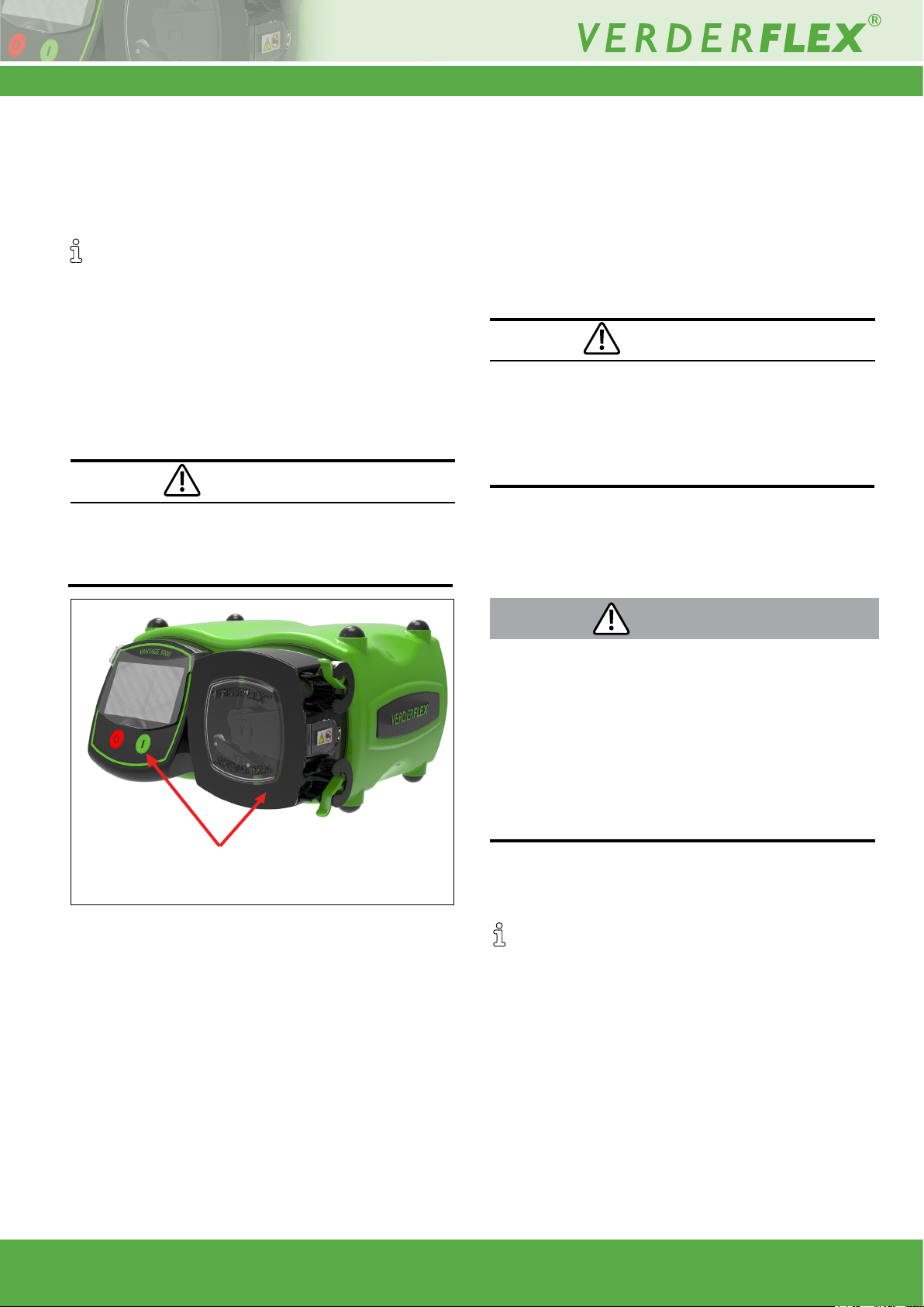
CAUTION
Pump damage caused by lifting
u Do not lift the pump by the Screen Module or the Pump
Head as shown in the following illustration.
u The tube should be removed from the pump.
u The pumphead should be washed out, allowed to dry and
any external build up of product removed.
3.4 Interim Storage Before Using
the Pump
CAUTION
Pump damage caused by interim storage
u Allow the pump to reach ambient temperature before
use.
u Please observe the storage recommendations and use-
by dates which apply to tubing you may wish to bring into
service after storage.
3.5 Disposal
With prolonged use, pump parts can be contaminated
by hazardous pumped liquids to such an extent that
cleaning may be insufcient.
WARNING
Do not lift the pump from the Screen Module
or the Pump Head
Figure 1 Lifting the pump
3.2 Storage Conditions
Make sure the storage location meets the following
conditions:
– Dry, humidity not to exceed 80%, non-condensing
– Out of direct sunlight
– Frost-free; temperature range -40° to +70°C
– Vibration-free
– Dust-free
Risk of poisoning and environmental damage by the
pumped liquid
u Use suitable personal protective equipment when carrying
out any work on the pump.
u Prior to disposal of the pump:
– Collect and dispose of any leaking pumped liquid in
accordance with local regulations.
– Neutralize residues of pumped liquid in the pump.
u Dispose of the pump and associated parts in accordance
with local regulations.
4 Layout and Function
The medium to be pumped does not come into contact
with any moving parts and is totally contained within the
tube. A roller passes along the length of the tube, compressing it. This motion forces the contents of the tube directly in front of the roller to move forward along the length
of the tube in a ‘positive displacement’ peristaltic movement. In the wake of the roller’s compressing action, the
natural elasticity of the tube material causes the tube to
recover and regain its round prole. This creates suction
pressure which rells the tube.
Tubing should be stored as supplied in their wrapper
and should be stored away from direct sunlight
and at room temperature.
Vantage 5000 1.4v-09.2019 8 | Page
4.1 Design Details of Vantage 5000
The Verderex Vantage 5000 range of tube pumps, provide a balanced selection of simple to operate peristaltic pumps.
The range offers the customer pump choices that are simple by design, with touchscreen interface and 4000:1 turndown
ratio with the stepper drive.
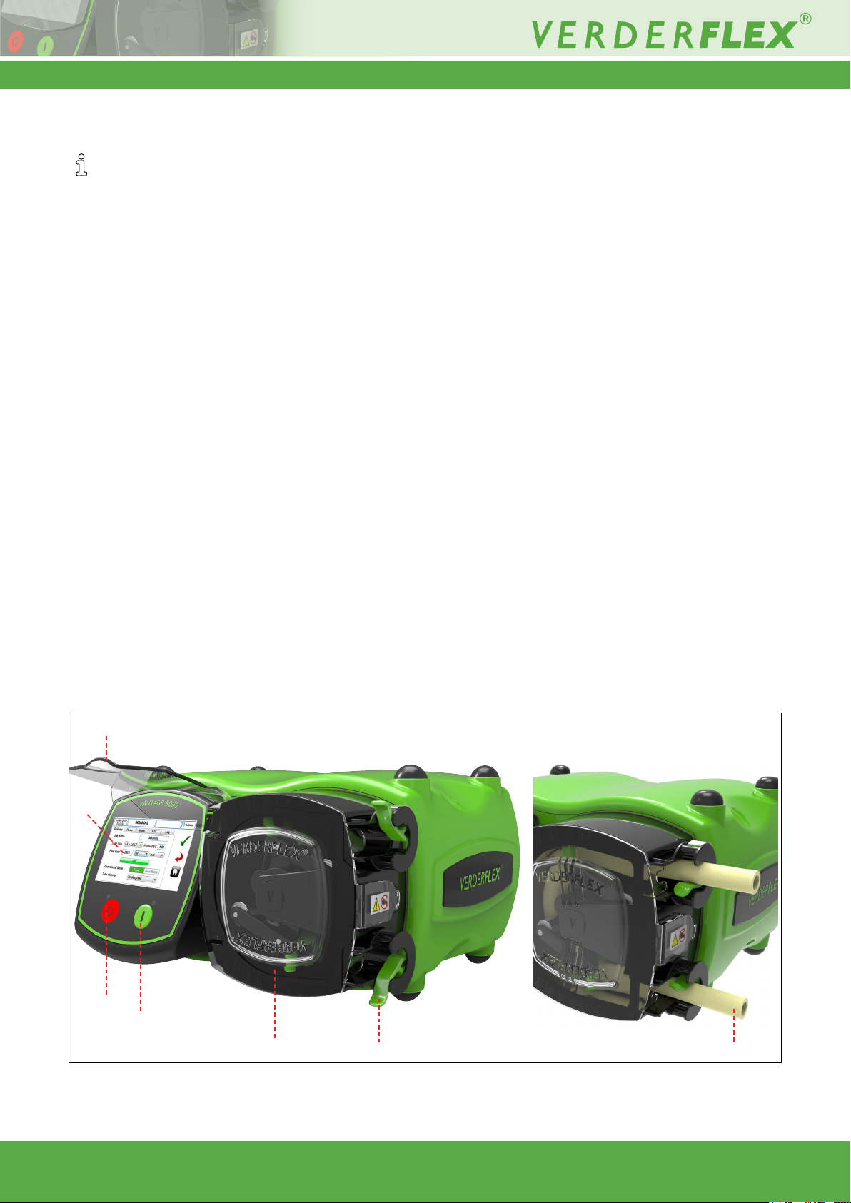
4.2 Vantage 5000 - an overview
A. SCREEN PROTECTOR
– Gently pull up the screen protector to touch the screen.
– Gently push the screen protector down after selecting the functions.
B. SCREEN MODULE
– Presents information to the user about the status of the pump.
– Accepts and implements the operators control instructions using the touchscreen.
– Use a suitable stylus or nger to select the functions. (g 6 User Interface - overview)
C. STOP BUTTON
– Stops the pump.
– RED LED illuminated when the pump is stopped
– FLASHING RED indicates an alarm or fault mode.
D. START BUTTON
– Starts the pump.
– GREEN LED illuminated when the pump is running.
– FLASHING GREEN LED indicates the pump is paused.
E. PUMP DOOR
– Must be closed for the pump to run.
– When opened during the operation, the pump will stop and the red led will ash.
F. CONTINUOUS TUBE CLAMP
– Clamps the loose tube in place or locate the tube assembly on xed element pumps.
G. CONTINUOUS TUBE
A
B
C
D
E
Figure 2 Key Parts of the Pump
Vantage 5000 1.4v-09.2019 9 | Page
F
G
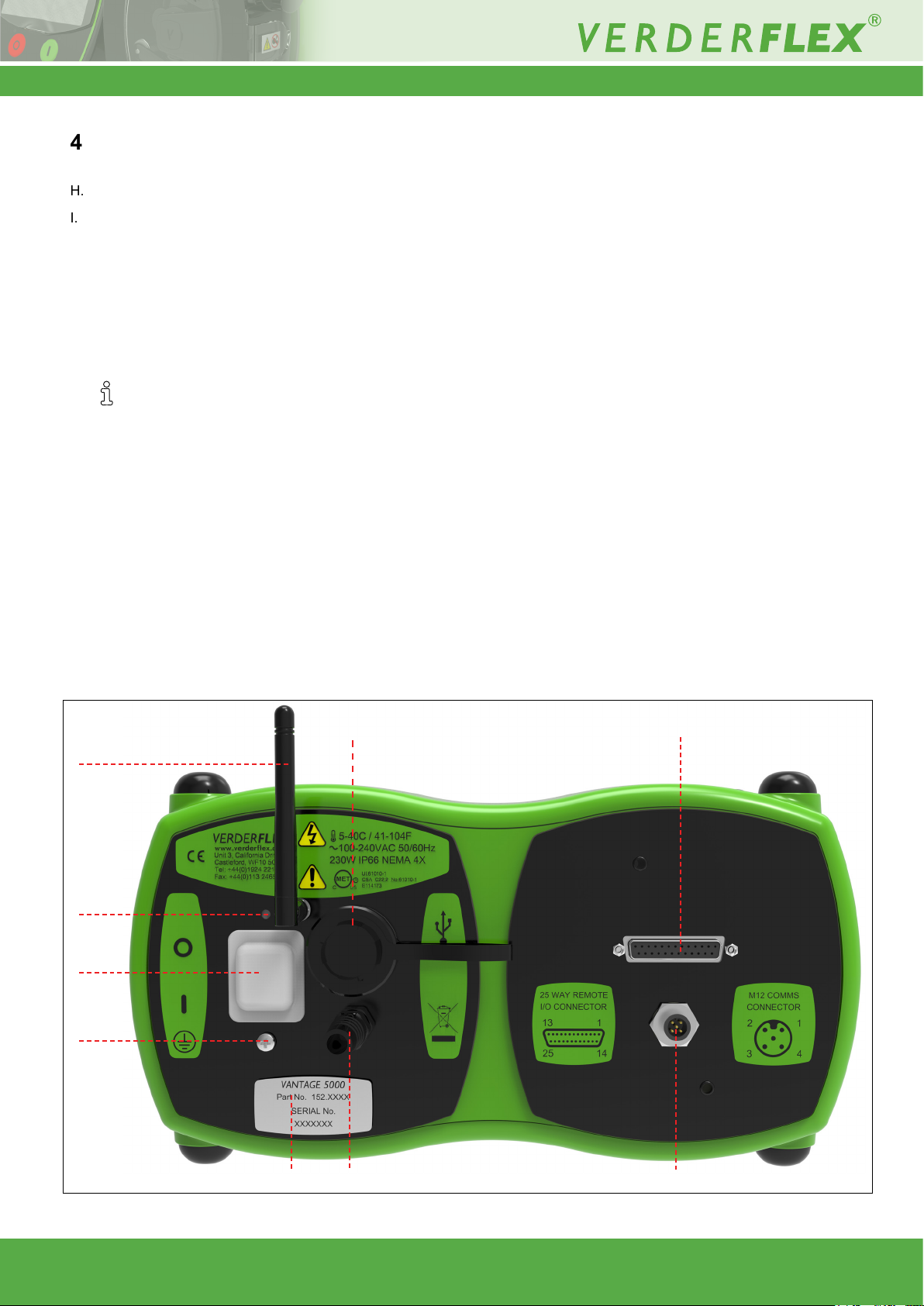
4.2 Vantage 5000 - an overview (continued)
H. BREATHER POINT (do not cover)
I. ON/OFF SWITCH
– Turns the pump ON or OFF.
J. EARTH POINT (M4)
K. NAME PLATE
– Part Number
– Model of Pump
– Serial Number
When requesting spares, the part number
and serial number should always be quoted.
L. POWER CABLE
M. M12 COMMS CONNECTOR (where tted)
– For digital RS485 and MODBUS® communications.
N. 25WAY REMOTE I/O CONNECTOR (where tted)
– Connection for footswitches, 0-10V DC & 4-20 mA remote controls.
– Provides connection for opto isolated BREAKOUT BOX modules.
O. USB 2.0 SOCKET CONNECTOR
– Pump can be backed up to USB memory.
– Pump programs can be loaded.
– Pump rmware can be updated.
P. WiFi Antenna
P
H
I
J
O
N
K
Figure 3 Back of the Pump
Vantage 5000 1.4v-09.2019 10 | Page
L
M
4.3 Layout
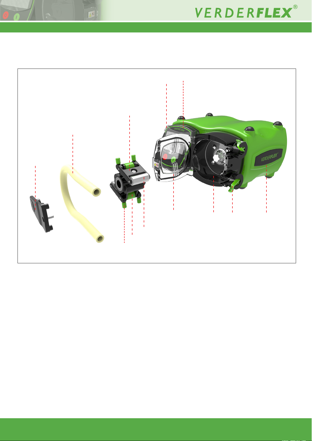
4.3.1 Vantage 5000 Exploded View - Continuous Tube
4
5
3
2
1
6
7
8 9
3.3
3.2
3.1
Figure 4 Vantage 5000 Exploded View - Continuous Tube
1 Bearing Strut 3.2 Horizontal Guide Rollers 6 Pump Door
2 Continuous Tube 3.3 Main Rollers 7 Pump Head
3 Rotor Assembly 4 Screen Protector 8 Tube Clamp
3.1 Vertical Guide Rollers 5 Screen Module 9 Pump Body
Vantage 5000 1.4v-09.2019 11 | Page
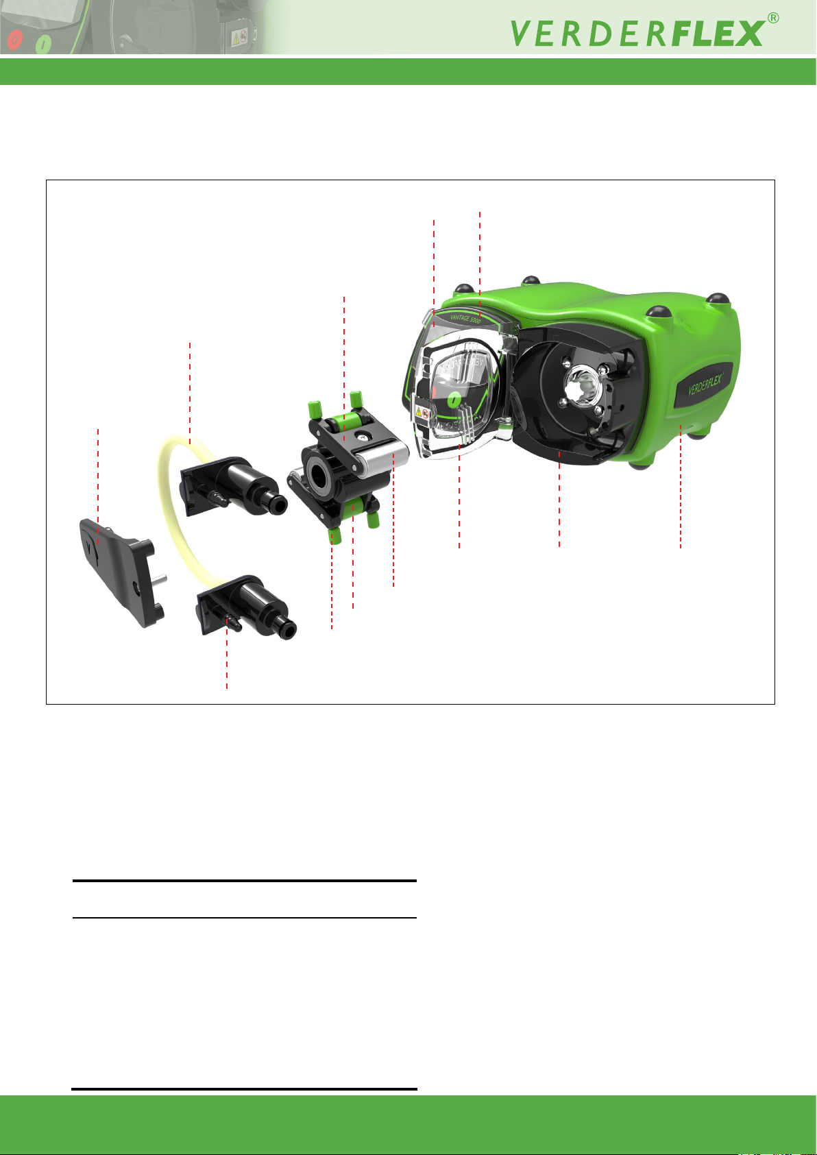
4.3.2 Vantage 5000 Exploded View - Tube Element
4
5
3
2
1
6
7
8
3.3
3.2
3.1
2.1
Figure 5 Vantage 5000 Exploded View - Tube Element
1 Bearing Strut 3.1 Vertical Guide Rollers 5 Screen Module
2 Tube Element 3.2 Horizontal Guide Rollers 6 Pump Door
2.1 Drain Port 3.3 Main Rollers 7 Pump Head
3 Rotor Assembly 4 Screen Protector 8 Pump Body
Note
The tube element is supplied with the drain port as shown in
Figure 5.
In case of an accidental tube burst, the upper most drain port
can be cut and may be used to provide ushing / neutralizing
solution. The lower drain port can be used to drain this ushing
liquid out from the pump.
If the customer wishes to use this feature, then the tip of the top
and bottom drain port should be removed.
Cut 1-2 mm off with the tip to open the port and connect suitable
tubing to a bunded area.
Vantage 5000 1.4v-09.2019 12 | Page

5 Installation and Connection
Wire colours are shown in the following table:
CAUTION
Material damage due to unauthorized modication on
pump
u Unauthorized modication will invalidate the warranty.
Note
u A non-return valve must be installed between the pump
and the discharge pipework to prevent sudden release of
uid into the pump head in the event of tube failure.
5.1 Electrical Installation
CAUTION
Failure to follow safe and proper electrical installation
practices may result in pump malfunction or dangerous
operation
u Make sure the pump is installed correctly.
u The pump is supplied with a pre-tted mains lead which is
not a user-replaceable part.
u The mains lead may have a fuse tted (country
dependant)
u The fuse should be replaced with an identical fuse in the
event of the fuse blowing.
u The pump is protected by a mechanical overload switch
built into the power switch.
5.1.1 Checking the Ambient Conditions
Conductor Name European Colouring American Colouring
Live Brown Black
Neutral Blue White
Earth (Ground) Green/Yellow Green
Table 5 Conductor colour coding
Note
We advise customers to consider using a commercial surge
suppression system for installations where there is a risk of
excessive electrical noise.
5.1.3 Protective Earthing/Grounding
CAUTION
Failure to earth the pump correctly can result in hazardous
voltages being present on the pump body
u The pump is designed to be permanently earthed and
MUST be connected as such.
u By default, the earth connection is made through the earth
pin on the mains lead.
u If the mains lead is of a “bare end” type, the earth cable
(denoted by a Green/Yellow marking) must be wired to the
earth.
u If an Earth/Ground is unavailable from the mains plug,
there is an earthing stud provided on the back of the pump
(g Figure 3) and this should be used in place of the earth
from the mains plug.
1. Make sure that the operating conditions are as per pump
specications (g Appendix A).
2. Make sure the required ambient conditions are within limits
(g Appendix A).
5.1.2 Connecting to a Power Supply
DANGER
Isolate power supply from the pump before performing the
installation.
1. The pump must be installed by a qualied individual if it is
to be permanently wired in place.
2. The pump must not be used if there is visible damage to
the mains cable or plug.
3. The pump must be positioned so that the disconnect
device is easily accessible.
4. The pump cable must be free from strain and the pump
weight must not be supported by the mains cable.
5. All cabling used to connect to the pump must be 0.75mm
Cross Sectional Area (CSA) minimum.
Note
Make sure a ground loop is not created through using both a
cable earth and the earthing stud.
If in any doubt, please contact a qualied electrician.
5.1.4 Electrical Isolation
1. The mains plug is the disconnection point for the pump
and is used for isolation from the mains.
2. The mains plug should therefore be readily accessible in
order to use as a disconnection point.
3. To isolate the pump, the mains plug is to be removed from
the wall outlet.
2
Vantage 5000 1.4v-09.2019 13 | Page
5.2 Installing the Tube
DANGER
u Isolate power supply from the pump before opening the
pump head.
CAUTION
u Make sure the tube is compatible with the rotor assembly.
u Before using a new tube assembly, make sure the pump is
run in the counter-clockwise direction for 1 minute.
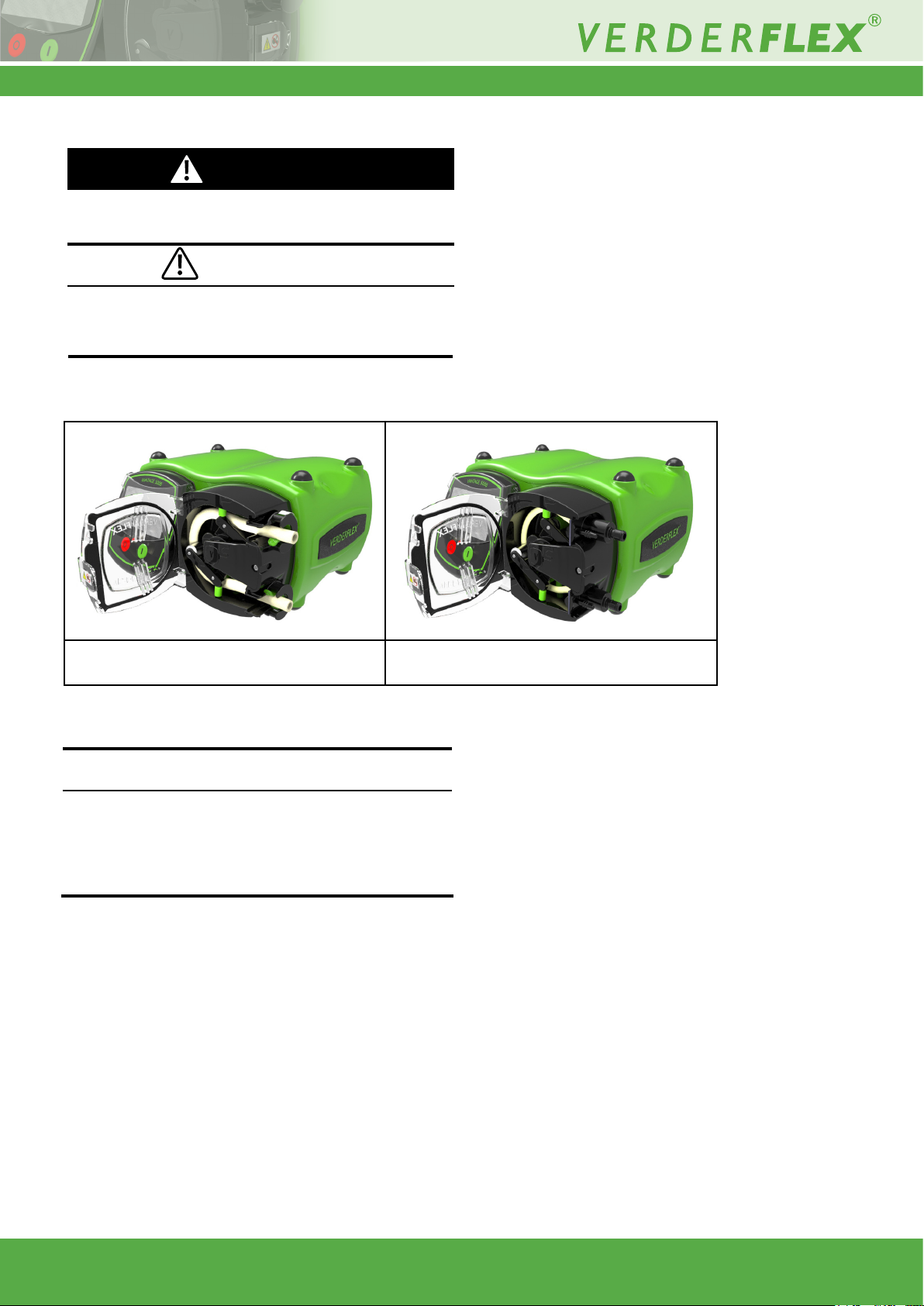
5.2.1 Vantage 5000 Pump Tube Options
1. Continuous Tube 2. Tube Element
Figure 6 Vantage 5000 Pump Tube Options
Note
The tube element incorporates a drain port as show in Figure 6
(2. Tube Element) which must be utilised to prevent build-up of
pressurised uid in the pump head in the event of tube failure.
Cut 1-2mm from the tip of the drain port and attach a sufcient
length of tubing into a bunded area or collection vessel.
Vantage 5000 1.4v-09.2019 14 | Page
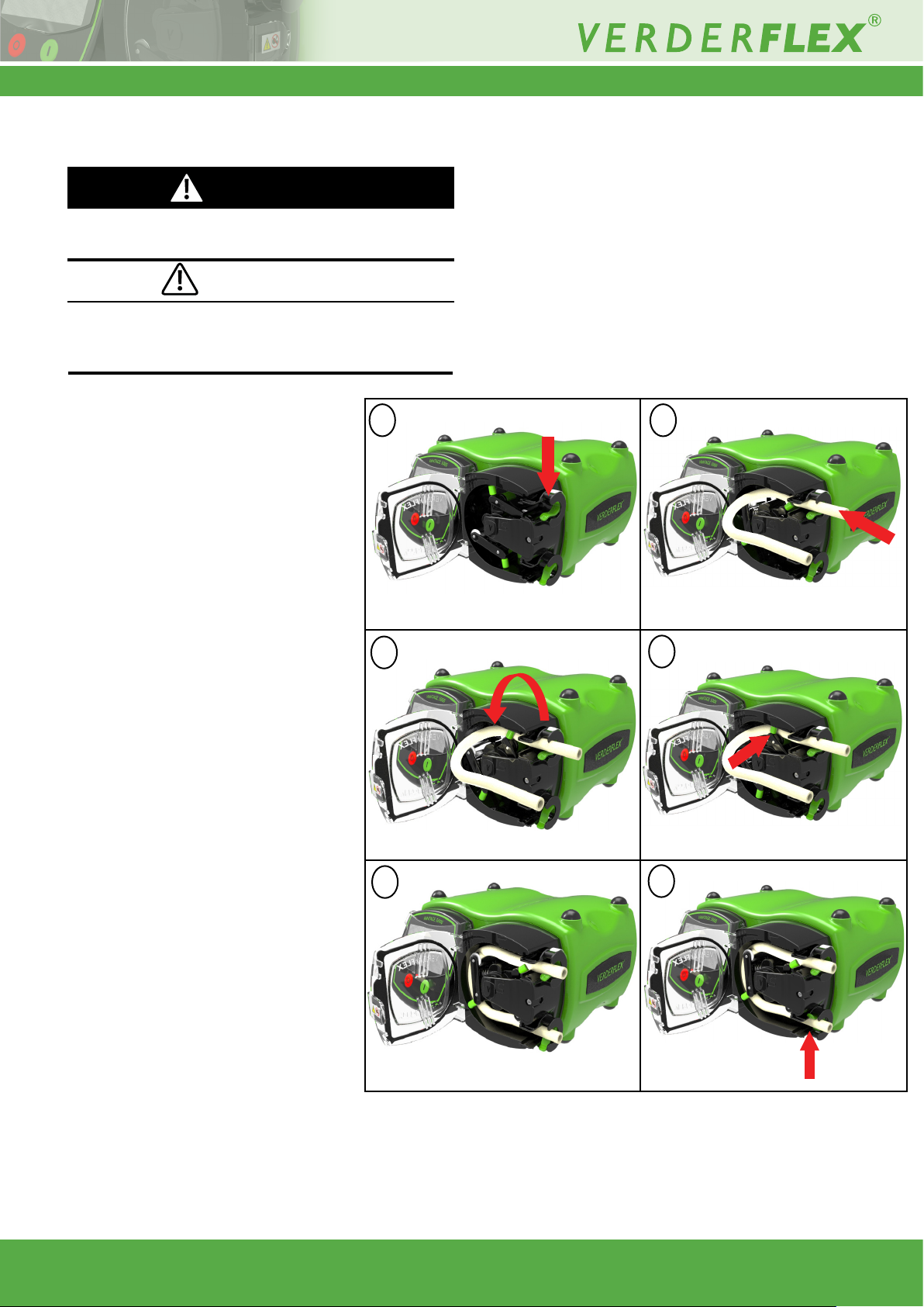
5.2.2 Installing Continuous Tube
DANGER
u Isolate power supply from the pump before opening the
pump head.
CAUTION
u Make sure the tube is compatible with the rotor assembly.
u Before using a new tube assembly, make sure the pump is
run in the counter-clockwise direction for 1 minute.
[ Ensure the Vantage 5000 pump is turned
off using the ON/OFF switch on the back
of the pump, if not, the rotor cannot be
turned by hand.
1. Open the pump door and push down the
tube clamp.
2. Insert the tube.
3. Rotate the rotor assembly using the vertical guide rollers in a counter-clockwise
direction.
3. Place the tube behind the vertical guide
rollers and continue to turn the rotor assembly in a counter-clockwise direction.
4. When performed correctly the main
rollers will compress the tube.
5. Release the tube clamp to lock the tube.
1 2
3
4
6. Push up the lower tube clamp and insert
the tube.
7. Once the tube is in place, close the pump
door before switching on the power sup-
ply.
Vantage 5000 1.4v-09.2019 15 | Page
5
Figure 6.1 Installing Continuous Tube
6
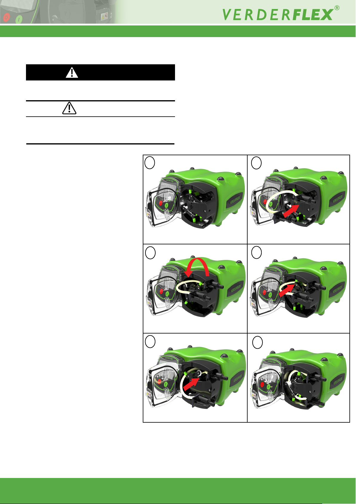
5.2.3 Installing the Tube Element
DANGER
u Isolate power supply from the pump before opening the
pump head.
CAUTION
u Make sure the tube is compatible with the rotor assembly.
u Before using a new tube assembly, make sure the pump is
run in the counter-clockwise direction for 1 minute.
[ Ensure the Vantage 5000 pump is turned
off using the ON/OFF switch on the back
of the pump, if not, the rotor cannot be
turned by hand.
1. Open the pump door.
2. Slide the tube element into the pump
head.
3. Rotate the rotor assembly using the
vertical guide rollers in a counter-clockwise direction.
4. Place the tube behind the vertical guide
rollers and continue to turn the rotor
assembly in counter-clockwise direction.
5. When performed correctly the main
rollers will compress the tube element.
6. Slide the lower tube element housing into
the pump head.
1
3
2
4
7. Once the tube is in place, close the pump
door before switching on the power sup-
ply.
Vantage 5000 1.4v-09.2019 16 | Page
5
Figure 6.2 Installing the Tube Element
6
6 User Interface - overview
This manual is a representation of the features and functions
in the Vantage 5000.
CAUTION
u The user must use a suitable stylus or nger to operate the
touch screen.
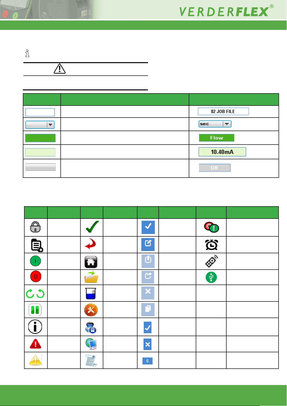
Symbols Meaning Examples
A box with a BLUE outline indicates an editable value
A box with a BLUE outline and an arrow indicates a selection
from a list
A shape lled in DARK GREEN indicates a selectable button
A shape coloured LIGHT GREEN indicates read-only value and
is there for information
A shape coloured ‘GREYED OUT’ indicates a usually editable
eld which can no longer be edited due to the current conditions
of the pump setup.
Table 6 Symbols used for software
The following icons are used throughout this document:
Icons Denition Icons Denition Icons Denition Icons Denition
Lock / Unlock Accept Activate
Main Menu
Start Button Home Import
Stop Button Job Files Export
Pumping
Direction
Pump Paused Settings Copy
Information
Go Back /
Cancel
Calibration Clear Job
Users / Passcodes
Edit
YES / Accept
25Way Remote I/O Connector
Real Time Clock
Enabled
Remote
Control Enabled
Jobs File/Settings File
Backed to the USB Drive
Fault Remote Control NO / Cancel
Warning Logs / History
Table 7 Icons used for software
Vantage 5000 1.4v-09.2019 17 | Page
Delete Characters
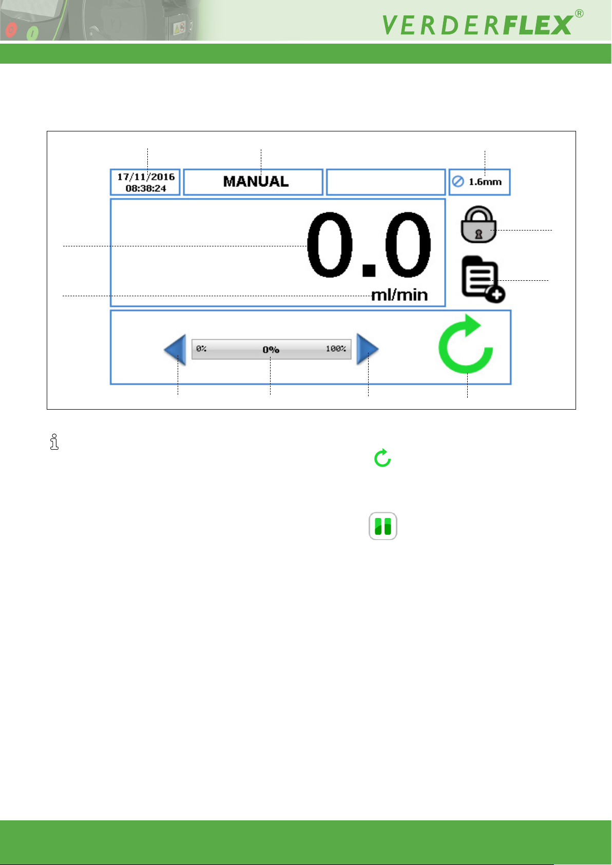
7 Screen Layout
7.1 Home Screen
6
7
1
2
3
Figure 7 Home Screen
When you switch on the pump for the rst time the Home
Screen will be as per Figure 7. Layout of the Home Screen
will change depending on how you program and operate
the pump unit.
This screen layout is available when the pump is operated
using “MANUAL” Job File only.
4
8
3
5. Pump Status symbols:
a. Displays the direction of rotation and RPM (if
the pump is running). In ‘Manual’ Job File only, the
direction of rotation can be changed by touching the
symbol on the Home Screen.
5
9
10
1. Displays the ow rate of the pump. The user can change
the ow rate in (g 7.4 Edit Job Files).
2. Displays the unit of ow rate. The user can change the
units of ow rate in (g 7.4 Edit Job Files).
3. Increment/Decrement arrow will increase/decrease the ow
rate only in the ‘Manual’ Job File. It can either be pressed
once which will increment/decrement the ow rate in steps,
or held down, which will gradually increase/decrease the
ow rate. It is a temporary change on the Home Screen
and does not change the ow rate in the Job File Menu.
(g 7.4 Edit Job Files).
4. The ow rate indicator displays the current ow rate as
a percentage of the maximum available ow rate for the
selected tube size.
b. Indicates the pump is in pause mode, where
there is a program active but the pump is temporarily
paused.
6. Displays the current time and date as specied in the
(g 7.6 Settings). It is a read-only display.
7. Displays the current Activated Job File. The user can
change the name of the Job File in (g 7.4 Edit Job Files).
It is a read-only display and will be displayed on every
screen.
8. Displays the Tube Size, as dened in the currently activated
Job File.
9. LOCK/UNLOCK
a. LOCK touchscreen, when pressed the back-light
dims and the screen locks. This avoids accidental key
presses.
b. UNLOCK touchscreen.
10. This icon allows the user to access the main menu.
(g 7.2 Main Menu)
Vantage 5000 1.4v-09.2019 18 | Page
 Loading...