

VERDER Verderflex Vantage 5000 User Manual
Peristaltic Cased Tube Pump
Appendix F
Breakout Box Vantage 5000
Version 1.6v-05/2019
Print-No. 01

Version 1.6v-05/2019
Print-No. 01
Vantage 5000
Appendix F 1.6v-05.2019 2 | Page

Table of contents
1. Appendix F Breakout Box
1.1 Installing the Breakout Box
1.1.1 Parts for Reference
1.1.2 Installation Instructions
1.2 Functionality
1.3 Voltage Supplies
1.4 Applied Voltage Signals
1.5 ‘Volt-free’ Signals
1.6 Output Signals
1.7 Analogue signals
Appendix F 1.6v-05.2019 3 | Page
Appendix F
1 Breakout Box
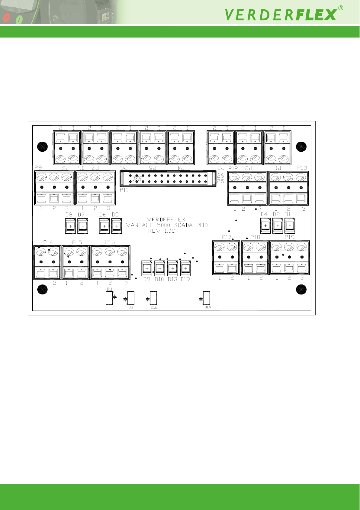
The breakout box has been provided to allow the user to make easy connections to all the remote input/output lines
on the 25 WAY Remote I/O Connector on the back of the Vantage 5000. For the connector number’s function of the
24VDC breakout box, see Table 1 and the 115VAC breakout box, see Table 2.
Figure 1 Breakout Box Diagram
Appendix F 1.6v-05.2019 4 | Page
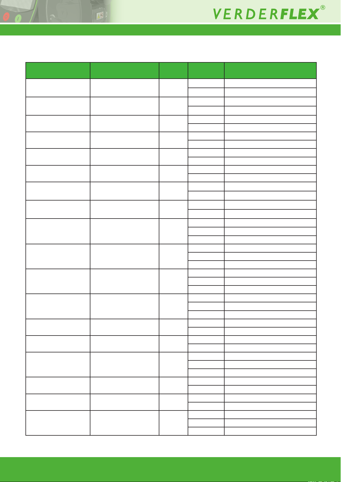
The following table shows the Vantage 5000 description of connector numbers on the 25 WAY Remote I/O Connector that are
provided with the 24VDC breakout box.
Connector Number Function Type Pin number Signal
P1 STA R T Input 1
2
P2 MANUAL/AUTO Input 1
2
+24V Relay Supply
0V Relay Supply
(1
+24V Relay Supply
0V Relay Supply
(1
P3 SLAVE ST EPS Input 1 Slave Steps Signal
2 0V Power Input Rail
P4 BUND DETECT Input 1 Bund Detect Signal
2 0V Power Input Rail
P5 PRODUCT DESTINATION
FULL
P6 PRODUCT SOURCE
EMPTY
P7 DIRECTION IN Input 1
P8 STOP Input 1
P9 GENERAL PURPOSE
OUTPUT 3
Input 1 Product Destination Full Signal
2 0V Power Input Rail
Input 1 Product Source Empty Signal
2 0V Power Input Rail
+24V Relay Supply
2
0V Relay Supply
(1
+24V Relay Supply
2
0V Relay Supply
(1
Output 1 Normally Closed
2 Normally Open
3 Common
P10 GENERAL PURPOSE
OUTPUT 4
Output 1 Normally Closed
2 Normally Open
3 Common
P12 ANALOGUE IN Input 1 0-10V Input
2 0V Analogue Ground
3 4-20mA Input
P13 GENERAL PURPOSE
OUTPUT 2
Output 1 Normally Closed
2 Normally Open
3 Common
P14 EXTERNAL POWER Power 1 +24V Power Input Rail
2 0V Power Input Rail
P15 +24V PUMP SUPPLY Power 1 +24V Pump Power Rail
2 0V Pump Power Rail
P16 ANALOGUE OUT Output 1 0-10V Output
2 0V Analogue Ground
3 4-20mA Output
P17 MASTER STEPS Output 1 +24V Power Input Rail
2 Master Steps Signal
P18 +10V PUMP SUPPLY Power 1 +10V Pump Power Rail
2 0V Analogue Ground
P19 GENERAL PURPOSE
OUTPUT 1
Output 1 Normally Closed
2 Normally Open
3 Common
Table 1 Description of Connector Numbers for 24VDC Breakout Box
(1
Applies for the 24VDC breakout box only.
(1
(1
(1
(1
Appendix F 1.6v-05.2019 5 | Page
 Loading...