

VERDER Carbolite TZF Series, TZF 12/75/700, TZF 12/38/400, TZF 12/65/550, TZF 12/100/900 Installation, Operation & Maintenance Instructions Manual
CONTENTS
Section page
Installation, Operation &
Maintenance Instructions
1200°C Tube furnaces (3-zone)
types TZF
This manual is for the guidance of operators of the above Carbolite products
and should be read before the furnace is connected to the electricity supply.
Manuals are supplied separately for the furnace controllers
(and overtemperature controller when fitted).
Please read the controller manuals before operating the furnace.
1.0 INTRODUCTION
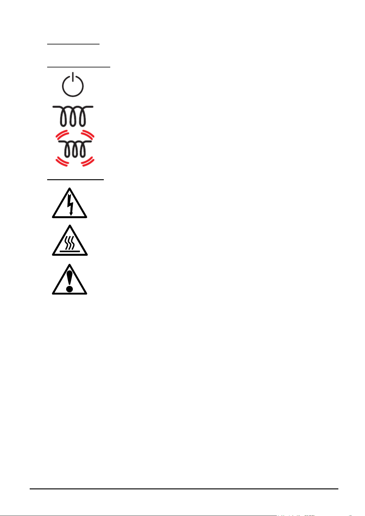
Instrument switch: when the instrument switch is operated the temperature
control circuit is energised.
Heat Light: the adjacent light glows or flashes to indicate that power is
being supplied to the elements
DANGER of electrical shock– read any warning printed by this symbol.
DANGER – hot surface. Read any warning printed by this symbol.
WARNING: all surfaces of a furnace may be hot.
DANGER – read any warning printed by this symbol.
Heat Switch: the switch disconnects power to the heating elements; unless
this switch is off there is a danger of electric shock when inserting objects
into the furnace
1.1 Switches and Lights
1.2 Warning Symbols
2 MF12 3.12
2.0 INSTALLATION
2.1 Unpacking & Handling
When unpacking or moving the furnace always lift it by its base or by both ends of the main body.
Never lift it by its work tube or the surrounding insulation. For the larger models, or where the
furnace and control box are not fixed together, use two people to carry the furnace.
Remove any packing material from inside the furnace before use.
NOTE: This product contains Refractory Ceramic Fibre (better described as Alumino Silicate
Wool) for precautions and advice in handling this material see the ‘Repairs and Replacements’
section.
2.2 Siting
Place the furnace in a well ventilated room, away from other sources of heat, and on a surface
which is resistant to accidental spillage of hot materials. Do not mount the furnace on an
inflammable surface.
Ensure that there is free space around the furnace. Do not obstruct any of the vents in the control
section: they are needed to keep the controls cool.
Ensure that the furnace is placed in such a way that it can be quickly switched off or disconnected
from the electrical supply - see below.
2.3 Setting Up
A furnace ordered for vertical use has a small clip or plate at one end to prevent a wound tube
element or a work tube from slipping downwards. Mount the furnace so that this clip is at the
bottom. In models with one thermocouple the thermocouple should be near the top rather than the
bottom.
If the furnace is supplied with a separate work tube or any accessories fit these into position.
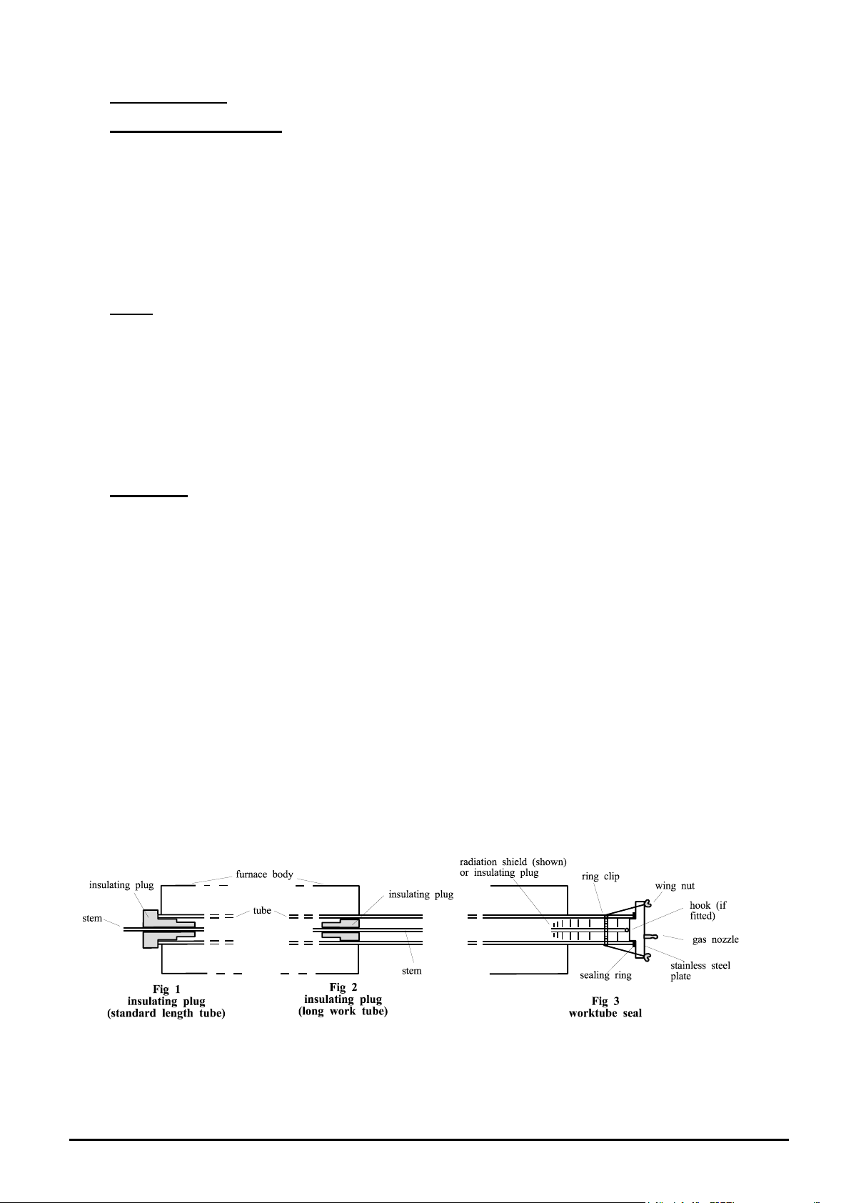
For optimum temperature uniformity, insulating plugs should be placed in the tube ends as shown
in fig.1. With a long work tube, the stem of the plug assembly should line up with the end of the
tube as in fig.2. Alignment of radiation shields is similar to that of plugs.
If stainless steel seals with gas inlets are supplied they are to be fitted as shown in fig.3; the stem
of any insulating plug should touch the seal. Stainless steel seals for vertical use: a hook and eye
arrangement holds the upper insulating plug assembly; alternatively a gland nut.
Horizontal models: if heavy fittings are to be clamped to the end of an extended work tube they
can increase the bending stress at the centre of the tube. Support such fittings in such a way that
expansion of the tube is allowed.
If a metal work tube is being used in the furnace, ensure that it is earthed. In the case of wound-
tube models (TZF) it should be mounted so as not to touch the furnace ceramic tube. See the safety
warning in section 3.4.
MF12 3.12 3
2.4 Electrical Connections
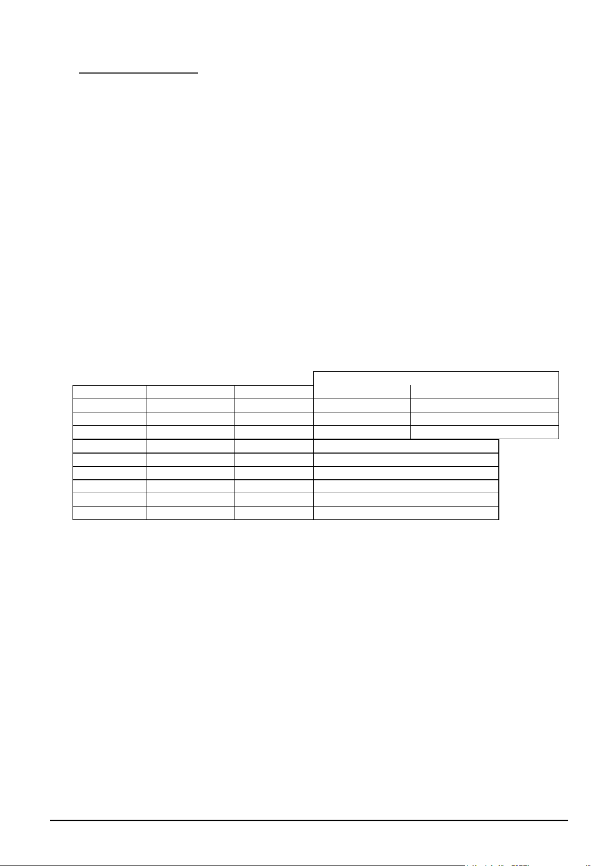
CONNECTION DETAILS
supply type
Supply
Terminal label
Cable colour
Live-Neutral
Reversible or Live-Live
1-phase
L
Brown
To live
to either power conductor
N
Blue
To neutral
to the other power conductor
PE
Green/Yellow
To earth (ground)
to earth (ground)
supply
Terminal label
Cable colour
2- or 3-phase
L1
Black
to phase 1
L2
Black
to phase 2
L3
Black
to phase 3 except 2-phase
N
Light Blue
to neutral except delta
PE
Green/Yellow
to earth (ground)
Connection by a qualified electrician is recommended.
The furnaces covered by this manual may be ordered for single phase A.C. supply, which may be
Live to Neutral non-reversible, Live to Neutral reversible or Live to Live. Some models can be
supplied for three phase use; some for use on two phases of a three phase with neutral supply (one
phase unused).
Check the furnace rating label before connection. The supply voltage should agree with the voltage
on the label, and the supply capacity should be sufficient for the amperage on the label.
The supply should be fused at the next size equal to or higher than the amperage on the label. A
table of the most common fuse ratings is also given in section 8.1 of this manual. Where a supply
cable is present there are internal supply fuses; customer fusing is preferred but not essential.
Furnace with supply cable: either wire directly to an isolator or fit with a line plug.
Furnace without supply cable: a permanent connection to a fused and isolated supply should be
made to the internal terminals after temporary removal of the furnace back panel.
Connection by line plug: the plug should be within reach of the operator, and should be quickly
removable.
Connection to isolating switch: this should operate on both conductors (single phase) or on all live
conductors (three phase), and should be within reach of the operator.
The supply MUST incorporate an earth (ground).
4 MF12 3.12

3.0 OPERATION
Home
List
Access
List
°C/F/k
ACCS
°C/F/k
codE
0.0
Zone temperature
difference; use /
to access offset
home list
for factory access to lists
and parameters not
available to the operator
OP.Hi
Output
oP
power limit
setting, if
present
The instructions for operating the temperature controller are given in a separate manual.
If the furnace is fitted with a time switch, see also the supplementary manual MS03.
If cascade control is fitted, see the supplementary manual MS07.
3.1 3-zone Control Methods
The models in this manual are typically designed to achieve an extended uniform temperature zone
by the use of three control zones. The control zones are typically linked so that they are all follow
the central controller in a master-slave approach; there are two ways of doing this. Alternatively
independent control zones may be ordered. There are thus three control methods (A, B & C).
A. Back-to-Back Thermocouples
This is the most commonly supplied option.
The central zone of the work tube is controlled directly by the central temperature controller. Each
end zone thermocouple is wired in opposition to a central reference thermocouple, and the small
voltage resulting when the zones are at different temperatures is used by the end zone controller.
The circuit diagram in section 7.1 shown the thermocouple arrangement.
Set the "setpoint" of the end zone controllers to zero. Alternatively, a small temperature difference
(offset) can be created by setting a non-zero value, but the sum of the main controller set-point and
the slave controller offset MUST NOT exceed the furnace maximum temperature. The "measured
temperature" display shows the actual offset.
To alter the setpoint (with the display at “home”), press Down or Up once to display the
setpoint; press again or hold down to adjust it. The display returns to the measured temperature
offset when no key is pressed for 0.5 seconds.
Sometimes a furnace using this type of control does not cool down: the end controllers try to
remain at the central temperature. Should this occur, contact Carbolite’s technical department.
2132 Slave Controller Navigation Diagram
B. Retransmission of Setpoint using Broadcast comms
When this is ordered there are three independent thermocouples connected to the three
controllers. The controllers are linked together, the central controller communicating the desired
setpoint to the end controllers.
Additional communication modules are fitted in the controllers, rather than an additional
thermocouple as in A. The communication between the controllers of the Eurotherm 3000 series is
known as Broadcast comms.
It is possible to switch off the linked control and allow the controllers to work independently. In
level 2 of the end zone controllers (see controller operating instruction), scroll to L-r. Where the
end zone controller is a 3216 use the up down and select NO. Where the end zone controller
is a 3508 use the up down to select SP1, (SP1 = Local, and SP2 = Remote). There is no
need to alter the centre controller.
It is possible to use local trim in the end zone controllers to enter a positive or negative adjustment
from the centre zone temperature. Once entered this trim will always be added or subtracted from
MF12 3.12 5
 Loading...