

VERDER Jec JRZL220, Jec JRZL105, Jec JRZL Series, Jec JRZL120, Jec JRZL225 Series Manual
...
ATEX Manual
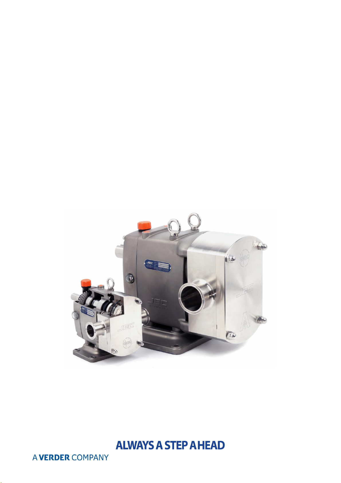
Rotary pumps
in a Hazardous Environment (Acc. to 2014/34/EU)

1
CONTENTS
Certificates _JRZL series
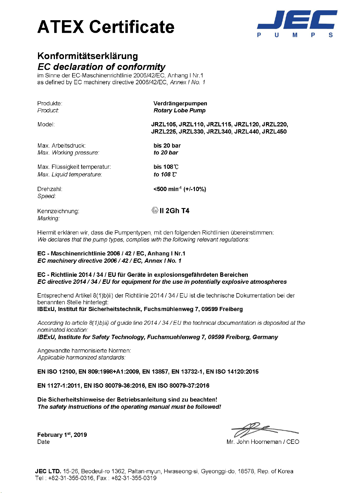
ATEX (European Explosion proof certification) …………………………………………………………
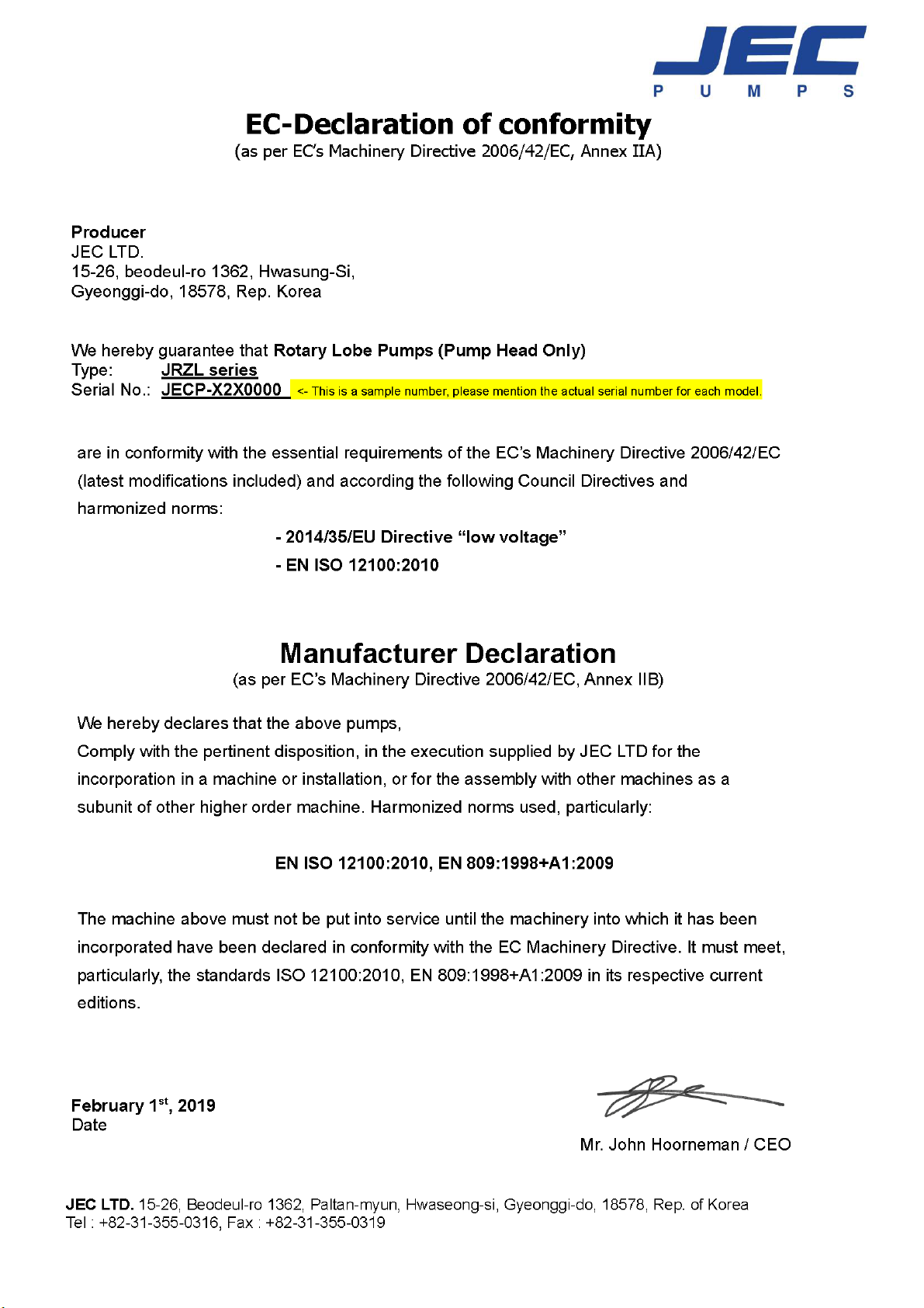
CE(Declaration of conformity) …………………………………………………………………………………
Certificates _JRZP series
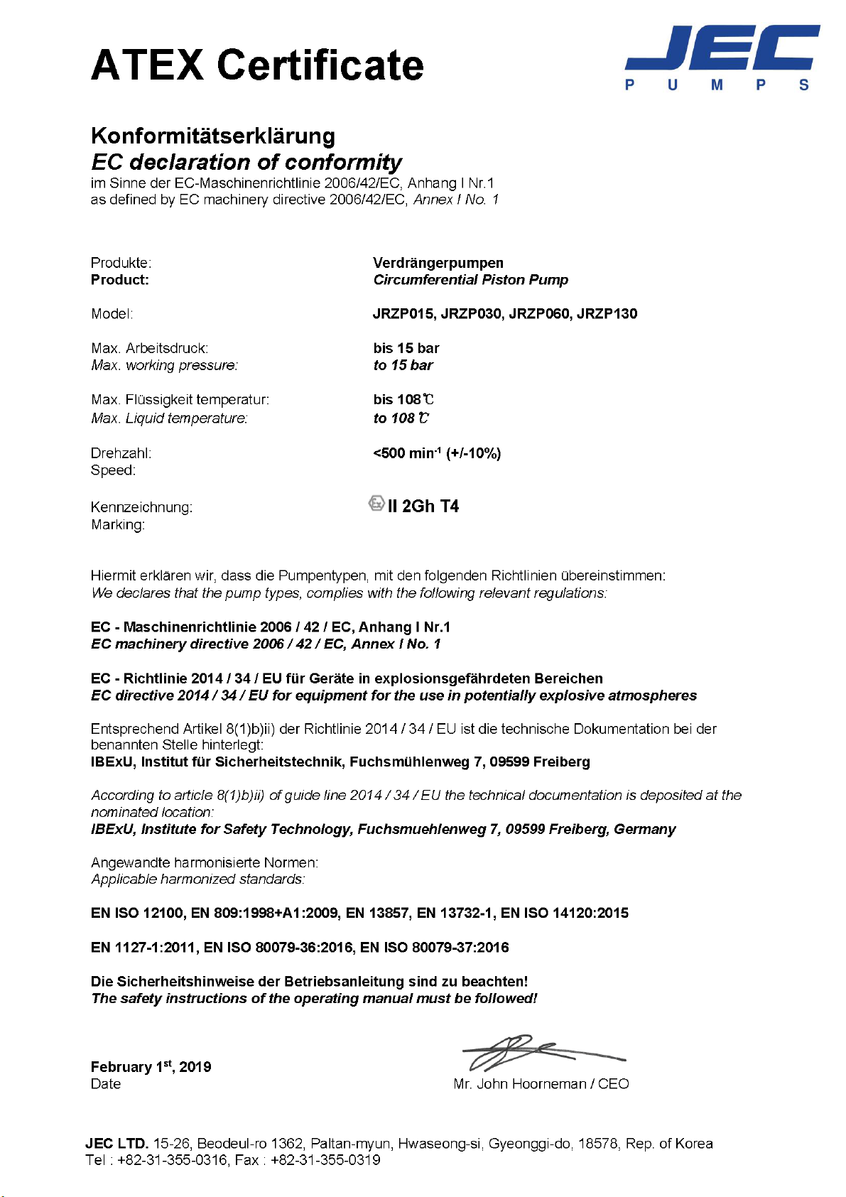
ATEX (European Explosion proof certification) …………………………………………………………
CE(Declaration of conformity) …………………………………………………………………………………
Introduction
Preliminary information ……………………………………………………………………………………………
Validity ……………………………………………………………………………………………………………………
Safety notes
Symbols ……………………………………………………………………………………………………………………
ATEX certificates and pump markings ………………………………………………………………………
Personnel …………………………………………………………………………………………………………………
Unauthorized modifications ………………………………………………………………………………………
Installation and start up
Location and surroundings ………………………………………………………………………………………
Electrical connections ………………………………………………………………………………………………
Grounding ………………………………………………………………………………………………………………
Filling procedure ………………………………………………………………………………………………………
Operation and maintenance
Operation …………………………………………………………………………………………………………………
Maintenance and service …………………………………………………………………………………………
Dismantling / Re-assembly ………………………………………………………………………………………
2
3
4
5
6
6
7
7
7
8
8
8
9
9
9
10
11
2
3
4
5

6
Introduction
Preliminary Information
Applications in sites with potentially explosive atmosphere require particular attention
concerning installation, operation, maintenance and supervision. The main information about
the pumps is contained in the general manual.
All safety regulations, standards and procedures must be followed to avoid personal injury,
damage to the equipment and environmental contamination. Personnel involved with the
installation, start-up, operation, maintenance or service must review and follow these
instructions.
Our warranty does not apply to any device which has been subject to improper use and
negligence.
Validity
This document refers to JEC rotary pumps. The serial number is indicated on the label.
Safety Notes
The operating range should never be exceeded. See specification for limits.
Provisional repair and improper spare parts are inconsistent with the ATEX regulations. To
maintain the explosion protection, the use of original JEC spare parts is mandatory.
Tubes and protective devices should not be impaired, bended etc. (never climb onto any
component).
All other components connected to the pump (driving elements, couplings, valves, fittings,
measuring instruments etc.) must meet at least the same safety requirements acc. to
2014/34/EU.
7
Symbols
An operating procedure, which, if not strictly observed, can result in personal injury
or environmental contamination
A procedure, essential to avoid damage to the equipment.
Important information that should not be overlooked, otherwise the functionality of
the pump is reduced.
ATEX Certificates and Pump Markings
II 2 G h T4
Marking and JEC certificate are valid only for pump resp. pump head, not for the
motor! The pump complies with the requirements of the Council Directive
2014/34/EU, in a hazardous atmosphere (group II), consisting in a mixture of gas
and air (G). The safety category is 2, and the temperature class T4. This determines
an upper limit of 135°C for the delivered liquid.
The motor requires its own declaration of conformity, issued by the corresponding
manufacturer. The temperatures resulting from the pump operation should not be
in excess of the admissible values at the motor shaft and the motor flange,
otherwise the safety cannot be guaranteed. In case of doubt, consult the
manufacturer.
For motors with flameproof enclosure Eexde II CT4: Frequency 5 to
87Hz
Personnel
The installation, operation and maintenance of the pump must be in accordance with all of the
user and local regulatory standards and procedures. Refer installation to qualified and trained
personnel with an adequate knowledge about safety measures in a potentially explosive
atmosphere.
8
Unauthorized Modifications
Unauthorized modifications, changes of design etc. are strictly forbidden.
Negligence during the installation work should be avoided. Consequential damages
are not covered by the warranty.
Installation and Start-Up
Location and Surroundings
Mount the pump in a suitable, accessible location. To protect the motor from
overheating, provide sufficient room for ventilation. A minimum clearance to
adjacent parts and walls should be maintained.
A further potential danger source are distorted tubes. As the pump tolerances are
quite narrow, a tube spoiled by bending may introduce friction to the system,
entailing the generation of inadmissible heat.
RPM max. <500 min
Electrical Connections
All electrical connections must be made according to local wiring regulations and electrical code.
These tasks are reserved to a qualified electrician. Maximum power values, issued by the motor
manufacturer, must be observed. A protective motor switch is strongly recommended.
If during the installation procedure the explosive atmosphere is already present, never verify
the direction of rotation by switching off and restarting the dry pump. A temperature rise with
frictional heat at the mechanical seals may cause an explosion hazard.
-1
(+/- 10%)
9
Grounding
Between pump and base plate or foundation, a potential equalization line must be
provided.
Filling Procedure
During operation, the inside is usually completely filled, so an explosive atmosphere
is absent. By this reason, filling/De-aerating the pump and the suction line before
starting-up is mandatory.
A dry run can be dangerous, particularly in the zone of the rotating mechanical seal.
If the formation of gas bubbles and pockets in the area of the mechanical seal
cannot be excluded during operation, special monitoring methods must be applied.
For a vertically mounted pump, this is always the case.
One more time: Dry running is dangerous and could result in serious
injury or death, or damage to the equipment!
Operation and Maintenance
Operation
It is obvious, that a safe operation in a hazardous location is only possible with a careful respect
of the specification – or there will be the risk of an uncontrollable temperature rise. It is also
forbidden to lock the suction line for a longer time, because this will create friction energy and
an accumulation of heat.
When working with a locked pressure line, pump or tubes may burst.
During starting-up, the suction valve should be totally opened, and the valve of the pressure
side partially. Thus the operating range of the pump will be observed.
10
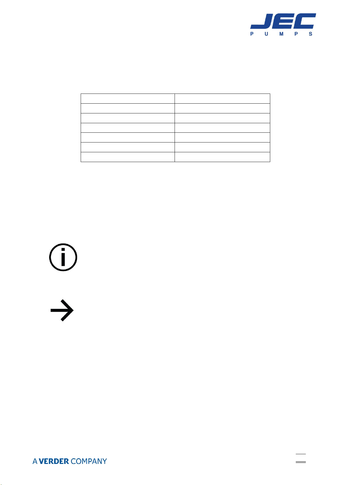
Class
Temperature
T1
450°C
T2
300°C
T3
200°C
T4
135°C
T5
100°C
T6
85°C
The maximum surface temperature has to be controlled weekly. If the values listed below are
exceeded, the pump has to be set out of action at once.
Admissible Temperatures
Admissible temperatures for transported liquid and pump
surface, depending on the ATEX temperature class.
Maintenance and Service
To reduce the occurrence of problems with the pump, the preventive maintenance
schedule must be followed, otherwise a safe operation in a hazardous location is
not guaranteed.
This is particularly important for wearing parts like mechanical seals, O-rings and
bearings. A regular visual inspection of static seals is mandatory.
Personnel should be sufficiently qualified and thoroughly familiar with the operation
of the pump, before starting any maintenance procedure. The same holds for
inspection and cleaning in the case of a possible dismantling and reassembling of
the pump. During this kind of work, an explosive atmosphere should not be
present.
Inspection and Maintenance Intervals:
Daily:
Oil level in the pump gearing, visual leakage control
Monthly / after 720 hours:
Oil level (viewing lass at the side of the gear case)
Yearly:
During the exchange of the mechanical seal, inspect and, if necessary, replace the
rolling bearing. O-rings and rotary seals sometimes have to be exchanged as well.
11
Dismantling / Re-assembly
Follow the steps listed in the general manual. Gap distances between rotating and
static parts are crucial, otherwise dangerous friction phenomena are possible. The
same holds for screw torques. Loose parts cannot be tolerated.
Another important parameter, by the reason mentioned above, is the correct
distance between rotating parts and covers.
 Loading...