

VERDER AIR VA 8 810.6012 Instructions-parts List Manual
INSTRUCTIONS - PARTS LIST
Parts
This manual contains important
warnings and information.
READ AND RETAIN FOR REFERENCE
INSTRUCTIONS
819.6247
VERDERAIR VA 8 Air-Operated
Diaphragm Pumps
0.7 MPa, 7 bar Maximum Incoming Air Pressure
0.7 MPa, 7 bar Maximum Fluid Working Pressure
* NOTE: Refer to the pump listing on page to determine the Model No of your pump.
Patent Pending
Contents
Rev. R
Warnings 2. . . . . . . . . . . . . . . . . . . . . . . . . . . . . . . . . . . . . . . . . .
Installation 4. . . . . . . . . . . . . . . . . . . . . . . . . . . . . . . . . . . . . . . . .
Operation 7. . . . . . . . . . . . . . . . . . . . . . . . . . . . . . . . . . . . . . . . . .
Maintenance 8. . . . . . . . . . . . . . . . . . . . . . . . . . . . . . . . . . . . . . . .
Troubleshooting 9. . . . . . . . . . . . . . . . . . . . . . . . . . . . . . . . . . . . .
Service 11. . . . . . . . . . . . . . . . . . . . . . . . . . . . . . . . . . . . . . . . . . .
Parts Listing 14. . . . . . . . . . . . . . . . . . . . . . . . . . . . . . . . . . . . . . .
Service Kit Listing 14. . . . . . . . . . . . . . . . . . . . . . . . . . . . . . . . . .
Parts Lists 15. . . . . . . . . . . . . . . . . . . . . . . . . . . . . . . . . . . . . . . . .
Parts Drawing 16. . . . . . . . . . . . . . . . . . . . . . . . . . . . . . . . . . . . . .
Torque Sequence 17. . . . . . . . . . . . . . . . . . . . . . . . . . . . . . . . . . .
Technical Data 19. . . . . . . . . . . . . . . . . . . . . . . . . . . . . . . . . . . . .
Dimensions and Mounting Hole Layout 19. . . . . . . . . . . . . . . .
Performance Charts 20. . . . . . . . . . . . . . . . . . . . . . . . . . . . . . . .
Customer/Guarantee 22. . . . . . . . . . . . . . . . . . . . . . . . . . . . . . . .
06176
Model 810.6012
shown
Warnings
Warning Symbol
Warning
This symbol alerts you to the possibility of serious injury or
death if you do not follow the instructions.
Warning
EQUIPMENT MISUSE HAZARD
Any misuse of the equipment or accessories, such as overpressurizing, modifying parts, using incompatible
INSTRUCTIONS
chemicals and fluids, or using worn or damaged parts, can cause them to rupture and result in splashing in the
eyes or on the skin, other serious injury, or fire, explosion or property damage.
This equipment is for professional use only. Observe all warnings. Read and understand all instruction manu-
als, warning labels, and tags before you operate this equipment. If you are not sure, or if you have questions
about installation or operation, call your VERDER distributor.
Never alter or modify any part of this equipment; doing so could cause it to malfunction.
Check all equipment regularly and repair or replace worn or damaged parts immediately.
Caution Symbol
Caution
This symbol alerts you to the possibility of damage to or destruction of equipment if you do not follow the instructions.
Never exceed the recommended working pressure or the maximum air inlet pressure stated on your pump or
in the Technical Data on page 19.
Do not exceed the maximum working pressure of the lowest rated component in your system. This equip-
ment has a 0.7 MPa (7 bar) maximum working pressure at 0.7 MPa (7 bar) maximum incoming air
pressure.
Be sure that all fluids and solvents used are chemically compatible with the wetted parts shown in the
Technical Data on page 19. Always read the manufacturer’s literature before you use fluid or solvent in the
pump.
Never move or lift a pump under pressure. If dropped, the fluid section may rupture. Always follow the
Pressure Relief Procedure on page 7 before you move or lift the pump.
2 819.6247
Warning
HAZARDOUS FLUIDS
Improper handling of hazardous fluids or inhaling toxic vapors can cause extremely serious injury or death from
splashing in the eyes, ingestion, or bodily contamination. Observe all the following precautions when you handle
hazardous or potentially hazardous fluids.
Know what fluid you are pumping and its specific hazards. Take precautions to avoid a toxic fluid spill.
Always wear appropriate clothing and equipment, such as eye protection and breathing apparatus, to protect
yourself.
Store hazardous fluid in an appropriate, approved container. Dispose of it according to all Local, State, and
Federal guidelines for hazardous fluids.
Secure the fluid outlet hose tightly into the receiving container to prevent it from coming loose and improperly
draining the fluid.
Pipe and dispose of the exhaust air safely, away from people, animals, and food handling areas. If the dia-
phragm fails, the fluid is exhausted along with the air. See Air Exhaust Ventilation on page 4.
FIRE AND EXPLOSION HAZARD
Static electricity is created by the flow of fluid through the pump and hose. If the equipment is not properly
grounded, sparking may occur. Sparks can ignite fumes from solvents and the fluid being pumped, dust particles, and other flammable substances, whether you are pumping indoors or outdoors, and can cause a fire or
explosion and serious injury and property damage.
To reduce the risk of static sparking, ground the pump and all other equipment used or located in the work
area. Check your local electrical code for detailed grounding instructions for your area and type of equipment. See Grounding on page 4.
If you experience any static sparking or even a slight shock while using this equipment, stop pumping
immediately. Check the entire system for proper grounding. Do not use the system again until you have
identified and corrected the problem.
Pipe and dispose of the exhaust air safely, away from all sources of ignition. If the diaphragm fails, the fluid is
exhausted along with the air. See Air Exhaust Ventilation on page 4.
Never use a polypropylene or Kynar pump with non-conductive flammable fluids as specified by your local
fire protection code. Refer to Grounding on page 4 for additional information. Consult your fluid supplier to
determine the conductivity or resistivity of your flui
Provide fresh air ventilation to avoid the buildup of flammable fumes from solvents or the fluid being pumped.
Do not smoke in the work area. Do not operate the equipment near a source of ignition or an open flame,
such as a pilot light.
Comply with all applicable local, state and national fire, electrical and safety regulations.
d.
819.6247 3
Installation
Tightening Threaded Fasteners Before First
Use
After unpacking the pump, and before using it for the first
time, check and retorque all external fasteners. See Service
for torque specifications. See Torque Sequence, page 17,
for torque sequence. After the first day of operation, retorque
the fasteners again. Although pump use varies, a general
guideline is to retorque fasteners every two months.
Use a compatible thread sealant on all male threads. Tighten
all connections firmly to avoid air or fluid leaks.
Caution
To avoid pump damage, do not overtighten the fittings to the
pump.
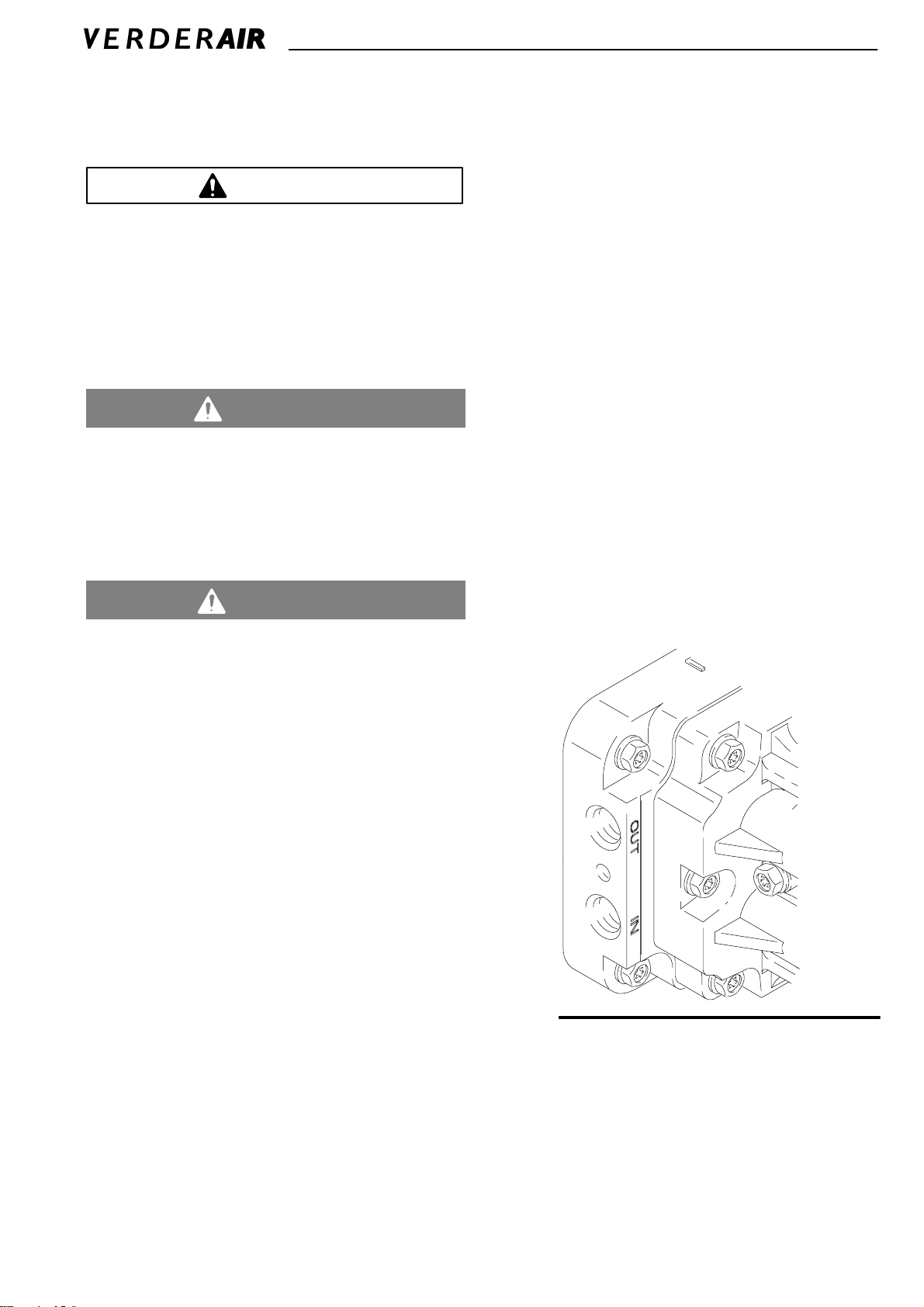
Grounding
Warning
This pump must be grounded. Before you
operate the pump, ground the system as
explained below. Also read the section FIRE
AND EXPLOSION HAZARD on page 3.
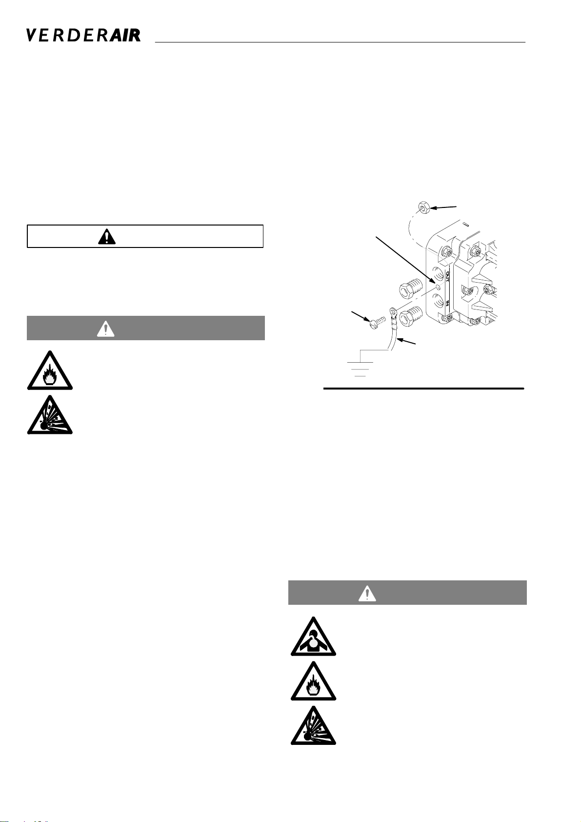
1. Place the nut in the nut catcher on the underside of the
manifold.
2. Insert the bolt through the loop end of the ground wire.
3. Insert the bolt through the hole on the pump manifold
and tighten it into the nut that you positioned in step 1.
4. Connect the clamp end of the ground wire to a true earth
ground.
B
grounding hole
C
A
Fig. 1
06179A
The acetal pump contains stainless steel
fibers which make the wetted parts conductive. Attaching the ground wire to one of the
grounding locations grounds the wetted
parts.
The polypropylene and Kynar pumps are not conduc-
tive. When you pump conductive flammable fluids, al-
ways ground the entire fluid system. Make sure the fluid
has an electrical path to a true earth ground, see Fig 1.
Never use a polypropylene or Kynar pump with non-con-
ductive flammable fluids as specified by your local fire
protection code.
US Code (NFPA 77 Static Electricity) recommends a conductivity greater than 50 x 10
meter) over your operating temperature range to reduce
the hazard of fire. Consult your fluid supplier to determine
the conductivity or resistivity of your fluid. The resistivity
must be less than 2 x 10
To reduce the risk of static sparking, ground the pump and all
other equipment used or located in the pumping area. Check
your local electrical code for detailed grounding instructions
for your area and type of equipment.
Acetal Pump Grounding Instructions
For polypropylene and Kynar pumps, see the warning
above.
Ground all of this equipment.
Pump: Connect a ground wire (A) and clamp, Part No.
819.0157. See Fig. 1. The pump grounding locations are on
the manifold between the inlet and outlet ports. Use the nut
(B) and bolt (C) that are provided with the pump, and install
as follows:
–12
Siemans/meter (mhos/
12
ohm-centimeters.
4 819.6247
Air and fluid hoses: Use only grounded hoses with a maximum of 500 ft (150 m) combined hose length to ensure
grounding continuity.
Air compressor: Follow the manufacturer’s recommendations.
All solvent pails used when flushing: Follow the local code.
Use only grounded metal pails, which are conductive. Do not
place the pail on a non-conductive surface, such as paper or
cardboard, which interrupts the grounding continuity.
Fluid supply container: Follow the local code.
Air Exhaust Ventilation
Warning
TOXIC FLUID HAZARD
Read the USING HAZARDOUS FLUIDS and
FIRE AND EXPLOSION HAZARD sections
on page 3 before you operate this pump.
Be sure the system is properly ventilated for
your type of installation. You must vent the
exhaust to a safe place, away from people,
animals or food handling areas when pumping flammable or hazardous fluids
If the diaphragm ruptures, the fluid being
pumped is exhausted with the air. Place a
container at the end of the air exhaust line to
catch fluid in case the diaphragm ruptures,
and disconnect the pump.
Installation
Mountings
Caution
The pump exhaust air may contain contaminants. If needed,
ventilate to a remote area to reduce possible fluid contamination. See Air Exhaust Ventilation on page 4.
Be sure the mounting can support the weight of the
pump, hoses, and accessories, as well as the stress
caused during operation.
For all mountings, be sure the pump is secured with
screws and nuts.
Warning
To reduce the risk of serious injury, splashing in the eyes
or on the skin, and toxic fluid spills, never move or lift a
pump under pressure. If dropped, the fluid section may
rupture. Always follow the Pressure Relief Procedure on
page 7 before you move or lift the pump.
Air Lines
Warning
Bleed-Type Master Air Valve and Fluid Drain Valve
A bleed-type master air valve and a fluid drain valve are
required on your system.
The bleed-type master air valve relieves air trapped between itself and the pump. Trapped air can cause the
pump to cycle unexpectedly, which could result in serious
bodily injury, including splashing in the eyes, injury from
moving parts, or contamination from hazardous fluids.
The fluid drain valve reduces the risk of serious bodily
injury, including splashing in the eyes or on the skin, or
contamination from hazardous fluids. Install the fluid drain
valve close to the pump’s fluid outlet to relieve pressure in
the hose if the hose becomes plugged.
b. Install a bleed-type master air valve downstream
from the air regulator, and use it to relieve trapped
air. See the Bleed-Type Master Air Valve and
Fluid Drain Valve warning at left. Locate another
bleed-type master air valve upstream from all air line
accessories, and use it to isolate the accessories
during cleaning and repair.
c. The air line filter removes harmful dirt and moisture
from the compressed air supply.
2. Install a flexible air hose between the accessories and
the pump air inlet. Screw the air line fitting into the air
inlet.
3. Do not restrict the exhaust port. Excessive exhaust
restriction can cause erratic pump operation.
Fluid Lines
Fig. 2. On each end of the fluid manifold are a fluid IN port
and a fluid OUT port. NOTE: Make sure the fluid OUT port
on the fluid manifold is mounted up. This will insure proper
pump priming. Fluid-in and fluid-out lines can be connected
on the same end, or opposite ends of the manifold. Plug
ports that are not used (plugs provided).
1. Mount the air line accessories on the wall or on a
bracket. Be sure the air line supplying the accessories
is grounded.
a. The pump speed can be controlled in one of two
ways: To control it on the air side, install an air
regulator. To control it on the fluid side, install a
fluid valve near the outlet.
Fig. 2
06179A
819.6247 5
Installation
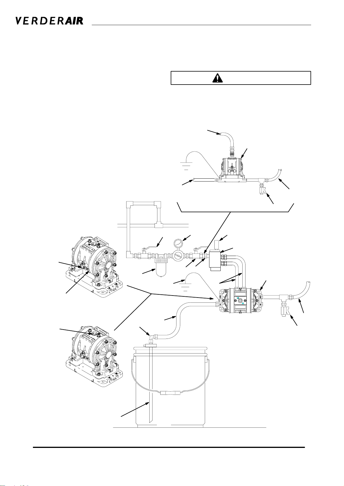
Typical Installation
The installation shown in Fig. 3 is only a guide to help select
and install a pump; they are not actual system designs.
Typical installation includes (not supplied by VERDER):
For solenoid operation: four-way, 5-port, 2-position sole-
noid valve with 1/4-in. ports. Schrader Bellows Part
No. C511ABB5 or equivalent.
KEY
A VERDERAIR VA 8 pump
B Bleed-type master air valve
(required for pump)
C Air line(s)
E Master air valve (for accessories)
F Air line filter
G Muffler
H Pump air regulator
J Fluid drain valve
(required on fluid outlet side of pump)
L Fluid suction line
N Fluid supply hose
T Bung adapter
U 4-way solenoid
Y Ground wire (required)
See page 4 for installation instructions.
PLC or timer. Consult your local industrial controls
distributor.
Caution
For solenoid operation, the pump must exhaust through the
solenoid. Failure to exhaust through solenoid could cause the
diaphragms to fail.
C
A
L
Internal Air Valve View
(shown upright for clarity)
N
J
Air line to Port A
Air line to Port B
Air line to inlet
Remote Solenoid Operated
Internal Air Valve Operated
E H
G
U
C
F
L
T
B
A
Y
C
Remote Solenoid View
N
J
Fig. 3
6 819.6247
L
06504
Operation
Pressure Relief Procedure
Warning
To reduce the risk of serious injury, including splashing fluid
in the eyes or on the skin, follow this procedure whenever
you are instructed to relieve pressure, when you shut off
the pump, and before you check, adjust, clean, move, or
repair any system equipment.
1. Shut off air and reserve air to the pump.
2. Open the dispensing valve if the system has one.
3. Open the fluid drain valve to relieve all system pressure,
and have a container ready to catch the drainage.
Flushing the Pump Before First Use
The pump was tested in water. If water could contaminate the
fluid you are pumping, flush it thoroughly with a compatible
solvent. Follow the procedure in Starting and Adjusting the
Pump.
Starting and Adjusting the Pump
Warning
To reduce the risk of serious injury, splashing in the eyes or
on the skin, and toxic fluid spills, never move or lift a pump
under pressure. If the pump is dropped, the fluid section
could rupture. Always follow the Pressure Relief Proce-
dure above before you move or lift the pump.
3. Place the suction tube (if used) in the fluid to be pumped.
4. Place the end of the outlet hose into an appropriate container.
5. Close the fluid drain valve.
6. With the air regulator closed, open all bleed-type master
air valves.
7. If the outlet hose has a dispensing device, hold it open
while continuing with step 8.
8. Slowly open the air regulator until the pump starts to
cycle. Allow the pump to cycle until all air is pushed out
of the lines and the pump is primed.
NOTE: To prime a remote solenoid-operated air
valve, operate the pump at a minimum 60 cpm
rate until the pump is fully primed.
Pump Shutdown
At the end of the work shift, and before you check, adjust,
clean, or repair the system, relieve air and fluid pressure.
Warning
To reduce the risk of serious injury whenever you are
instructed to relieve pressure, always follow the Pressure
Relief Procedure at left.
1. Be sure the pump is properly grounded. Read and follow
the instructions in Grounding on page 4.
2. Check all fittings to be sure they are tight. Be sure to use
a compatible liquid thread sealant on all male threads.
Tighten the fluid inlet and outlet fittings and plugs securely. Retorque all fasteners before start-up.
819.6247 7

Maintenance
Lubrication
The air valve is lubricated at the factory and designed to operate without additional lubrication.
If added lubrication is desired, every 500 hours of operation
(or monthly), remove the hose from the pump air inlet and
add two drops of machine oil to the air inlet.
Caution
Do not over-lubricate the pump. Excess oil is exhausted
through the muffler, which could contaminate your fluid supply or other equipment.
Tightening Threaded Connections
Before each use, check all hoses for wear or damage, and
replace as necessary. Be sure all threaded connections are
tight and free of leaks.
Check fasteners. Tighten or retorque as necessary. Although
pump use varies, a general guideline is to retorque fasteners
every two months. See Service for torque specifications. See
Torque Sequence, page 17, for torque sequence.
Flushing and Storage
Flush the pump to prevent the fluid from drying or freezing in
the pump and damaging it. Always flush the pump and re-
lieve the pressure before storing for any length of time. Use
a compatible solvent.
Warning
To reduce the risk of serious injury whenever you are
instructed to relieve pressure, always follow the Pressure
Relief Procedure on page 7.
If you are flushing, run the pump long enough to thoroughly
clean the pump and hoses, close the air regulator, and remove the suction hose from the solvent and place it in the
fluid to be pumped.
If you are shutting down the pump, remove the suction hose
from the fluid container, run the pump until the fluid is forced
out of the system, and shut off the air supply immediately.
8 819.6247
 Loading...