


VUT 180 P5B EC
Vents VUT 180 P5B EC, VUT 180 P5 EC, VUE 180 P5B EC, VUE 180 P5 EC, VUE 180 P5 User Manual
...
VUT 180 P5
VUE 180 P5
VUT 180 P5 EC
VUE 180 P5 EC
VUT 180 P5B EC
VUE 180 P5B EC
Air handling unit
USER’S MANUAL

2
www.ventilation-system.com
VUT/VUE 180 P5(B) (EC)
CONTENTS
Safety requirements .....................................................................................................................................................................2
Purpose ................................................................................................................................................................................................ 4
Delivery set ........................................................................................................................................................................................ 4
Designation key .............................................................................................................................................................................. 4
Technical data .................................................................................................................................................................................. 5
Unit design and operating principle ................................................................................................................................. 6
Installation and set-up................................................................................................................................................................ 8
Connection to power mains .................................................................................................................................................. 12
Unit control ....................................................................................................................................................................................... 13
Technical maintenance .............................................................................................................................................................. 14
Storage and transportation regulations .......................................................................................................................... 16
Manufacturer’s warranty ........................................................................................................................................................... 17
Certificate of acceptance .......................................................................................................................................................... 18
Seller information .......................................................................................................................................................................... 18
Installation certificate .................................................................................................................................................................. 18
Warranty card ...................................................................................................................................................................................18
This user’s manual is a main operating document intended for technical, maintenance, and operating staff.
The manual contains information about purpose, technical details, operating principle, design, and installation of the VUT/VUE 180 P5(B) (EC )
unit and all its modifications.
Technical and maintenance staff must have theoretical and practical training in the field of ventilation systems and should be able to
perform works in accordance with workplace safety rules as well as construction norms and standards applicable in the territory of the
country.
The information in this user’s manual is correct at the time of the document’s preparation.
The Company reserves the right to modify the technical characteristics, design, or configuration of its products at any time in order to
incorporate the latest technological developments.
No part of this publication may be reproduced, stored in a retrieval system, or transmitted, in any form or by any means in any information
search system or translated into any language in any form without the prior written permission of the Company.
SAFETY REQUIREMENTS
• Please read the user’s manual carefully prior to installing and operating the unit.
• All user’s manual requirements as well as the provisions of all the applicable local and national construction, electrical, and technical
norms and standards must be observed when installing and operating the unit.
• The warnings contained in the user’s manual must be considered most seriously since they contain vital personal safety information.
• Failure to follow the rules and safety precautions noted in this user’s manual may result in an injury or unit damage.
• After a careful reading of the manual, keep it for the entire service life of the unit.
• While transferring the unit control, the user’s manual must be turned over to the receiving operator.
UNIT INSTALLATION AND OPERATION SAFETY PRECAUTIONS
• Disconnect the unit from power mains prior
to any installation operations.
• The unit must be grounded!
• Do not lay the power cable of the unit in
close proximity to heating equipment.
• While installing the unit, follow the safety
regulations specific to the use of electric
tools.
3
www.ventilation-system.com
• Do not change the power cable length
at your own discretion. Do not bend the
power cable. Avoid damaging the power
cable. Do not put any foreign objects on the
power cable.
• Unpack the unit with care.
• Do not use damaged equipment or cables
when connecting the unit to power mains.
• Do not operate the unit outside the
temperature range stated in the user’s
manual. Do not operate the unit in
aggressive or explosive environments.
• Do not touch the unit controls with wet
hands. Do not carry out the installation and
maintenance operations with wet hands.
• Do not wash the unit with water. Protect
the electric parts of the unit against ingress
of water.
• Do not allow children to operate the unit.
• Disconnect the unit from power mains prior
to any technical maintenance.
• Do not store any explosive or highly
flammable substances in close proximity to
the unit.
• When the unit generates unusual sounds,
odour, or emits smoke, disconnect it from
power supply and contact the Seller.
• Do not open the unit during operation.
• Do not direct the air flow produced by the
unit towards open flame or ignition sources.
• Do not block the air duct when the unit is
switched on.
• In case of continuous operation of the unit,
periodically check the security of mounting.
• Do not sit on the unit and avoid placing
foreign objects on it.
• Use the unit only for its intended purpose.
• The unit should be protected from heat and
direct sunlight.
• Do not install near fire.
THE PRODUCT MUST BE DISPOSED SEPARATELY AT THE END OF ITS SERVICE LIFE.
DO NOT DISPOSE THE UNIT AS UNSORTED MUNICIPAL WASTE.
4
www.ventilation-system.com
VUT/VUE 180 P5(B) (EC)
Due to the ability to save heating energy by means of energy recovery, the unit is an important element of energy-efficient premises. The
unit is a component part and is not designed for stand-alone operation.
The unit is designed to ensure mechanical air exchange in houses, offices, hotels, cafés, conference halls and other utility and public
spaces as well as to recover the heat energy contained in the air extracted from the premises to warm up the filtered stream of supply air.
The unit is rated for continuous operation.
Transported air must not contain any flammable or explosive mixtures, evaporation of chemicals, sticky substances, fibrous materials,
coarse dust, soot and oil particles or environments favourable for the formation of hazardous substances (toxic substances, dust,
pathogenic germs).
The relative humidity of the transported air at a temperature of +20 °C should not exceed 80 %.
DELIVERY SET
NAME NUMBER
Air handling unit 1 pc.
User’s manual 1 pc.
Control panel user’s manual 1 pc.
Control panel 1 pc.
Installation kit 1 pc.
Packing box 1 pc.
DESIGNATION KEY
VUT 180 P 5 B EC
Motor type
_ – asynchronous
EC - electronically commutated
Additional components
_ – without a bypass
B - bypass
Casing design
Spigot orientation
P - suspended mounting, horizontal spigot orientation
Rated air ow [m
3
/h]
Series of units
VUT - heat recovery air handling unit
VUE - energy recovery air handling unit
PURPOSE
THE UNIT SHOULD NOT BE OPERATED BY CHILDREN OR PERSONS WITH REDUCED
PHYSICAL, MENTAL, OR SENSORY CAPACITIES, OR THOSE WITHOUT
THE APPROPRIATE TRAINING.
THE UNIT MUST BE INSTALLED AND CONNECTED ONLY BY PROPERLY QUALIFIED
PERSONNEL AFTER THE APPROPRIATE BRIEFING.
THE CHOICE OF UNIT INSTALLATION LOCATION MUST PREVENT UNAUTHORIZED
ACCESS BY UNATTENDED CHILDREN.
5
www.ventilation-system.com
TECHNICAL DATA
The unit is designed for indoor application with the ambient temperature ranging from +1 °C up to +40 °C and relative humidity up to
80 %.
To prevent condensation on the internal walls of the unit, it is necessary that the dew point temperature of transported air is 2-3 °C below
the surface temperature of the casing.
The unit is rated as a Class I electrical appliance. Hazardous parts access and water ingress protection rating:
• IP44 for the unit motors
• IP22 for the unit connected to the air ducts
The unit design is constantly being improved, so some models may be slightly different from those ones described in this manual.
TECHNICAL DATA
MODEL VUT 180 P5B VUE 180 P5B* VUT 180 P5 VUE 180 P5*
Voltage [V/50 (60) Hz] 1~220-240
Maximum fan power [W ] 87
117
Maximum unit current without a heater [A] 0.71
0.54
Maximum air flow [m
3
/h] 220
Sound pressure level at 3 m distance [dBA] 33 35
Transported air temperature [°C] from -25 up to +60
Casing material EPP
Insulation EPP (30-15 mm)
Filtering class of the extract filter G4
Filtering class of the supply filter G4, F7 G4 (F7 – optional)
Weight [kg] 14
Heat recovery efficiency [%] 86-98 79-94
86-98 79-94
Heat exchanger type counter-flow
Heat exchanger material
polystyrene
enthalpy
membrane
polystyrene
enthalpy
membrane
* The unit is equipped with an enthalpy heat exchanger that doesn’t require condensate drainage.
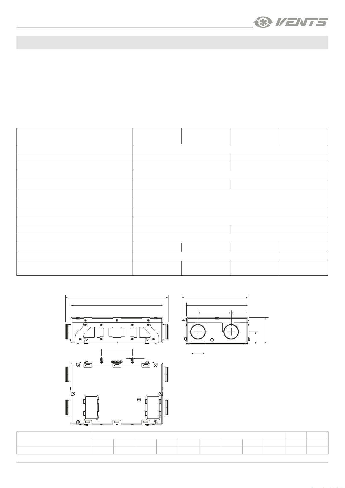
MODEL
DIMENSIONS [MM]
Ø D Ø D1 A A1 A2 B B1 B2 B3 H H1
VUT/VUE 180 P5(B) (EC)
150 18 1009 900 302 650 600 326 163 264 250
А B
H
H1
А1
А2
øD1
øD
B1
B3B2
6
www.ventilation-system.com
VUT/VUE 180 P5(B) (EC)
DESIGN AND OPERATING LOGIC
The unit has the following operating logic: warm stale extract air from the room flows into the unit, where it is filtered by the extract filter,
then air flows through the heat exchanger and is exhausted outside by the extract fan. Cold fresh air from the outside flows into the unit,
where it is cleaned by the supply filter.
Then the air flows through the heat exchanger and is directed to the room with the supply fan. Heat energy of warm extract air is
transferred to clean intake fresh air from the outside and warms it up. The air flows are fully separated while flowing through the heat
exchanger. Heat recovery minimizes heat losses, which reduces the cost of space heating in the cold season.
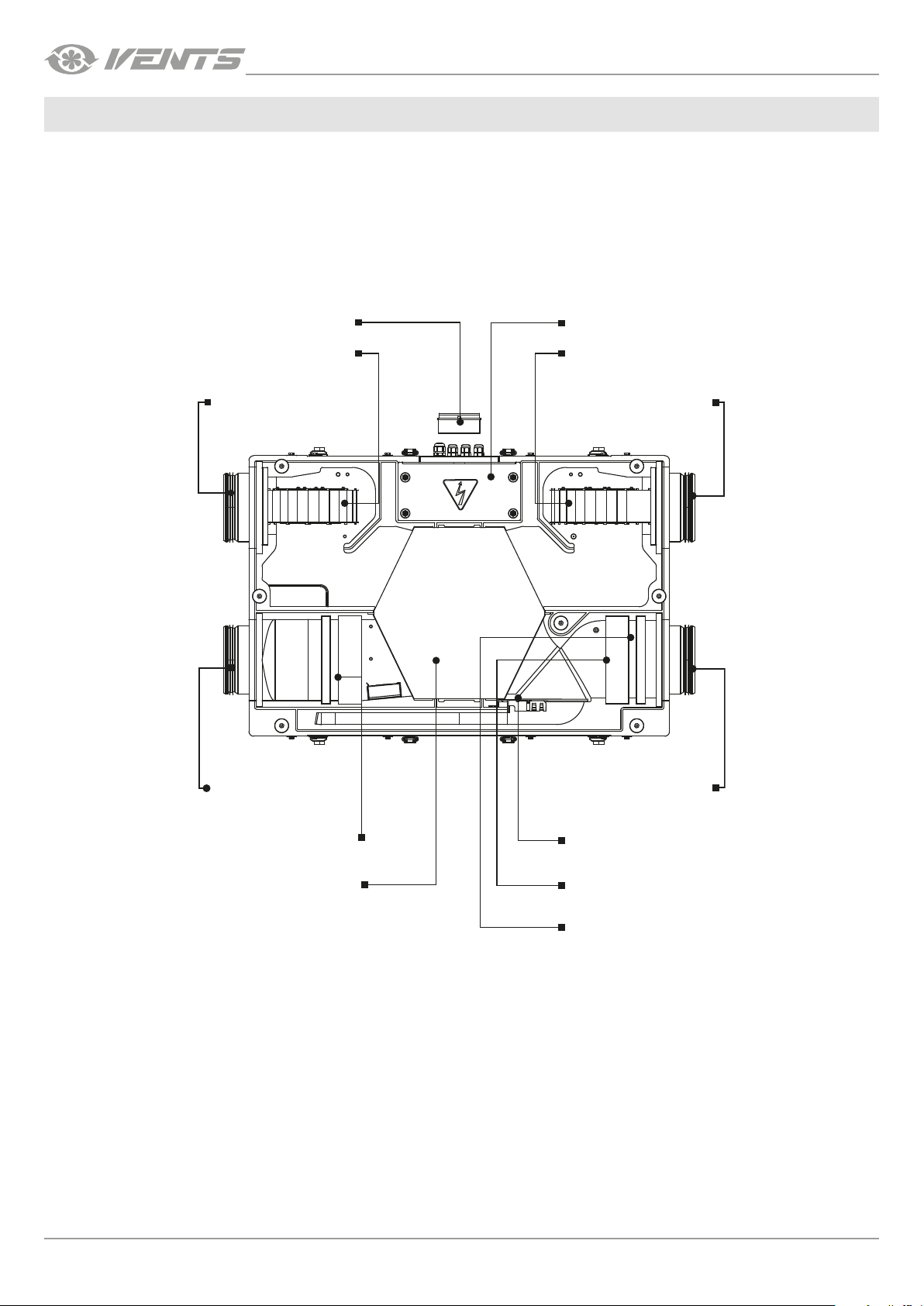
VUT 180 P5B EC UNIT DESIGN
Control panel Control unit
Extract fan
Supply fan
Supply air
Exhaust air
Intake air
Exhaust air
Extract lter G4
Heat exchanger
Bypass damper
Supply lter F7
Supply lter G4
The service side of the unit is equipped with detachable plates fixed by screws for filter cleaning and replacement operations. The control
unit is positioned inside the unit casing. The power cable and grounding cable are connected to the control unit via the electric lead-
ins placed at the side of the unit. The difference between the supply and extract air flow temperature leads to condensate generation.
Condensate is collected in the drain pan and is removed outside through the drain pipes.
Additional equipment for the unit is purchased separately as an accessory.
• HV2 humidity sensor (for units equipped with an A14 or an A21 control panel).
The unit with an installed humidity sensor maintains a set indoor humidity point. As the extract air humidity rises above the set point,
the system automatically switches to the maximum speed. As the humidity drops down below the set point the unit returns to the
previous mode. If the sensor is not factory installed, installation and connection (see page 8) are performed directly on site by a
service technician.
 Loading...