

Vents VUT 550 VB EC, VUT 350 V1B EC, VUT 160 VB EC, VUT 160 V1B EC, VUT 160 V1 EC User Manual
...Page 1
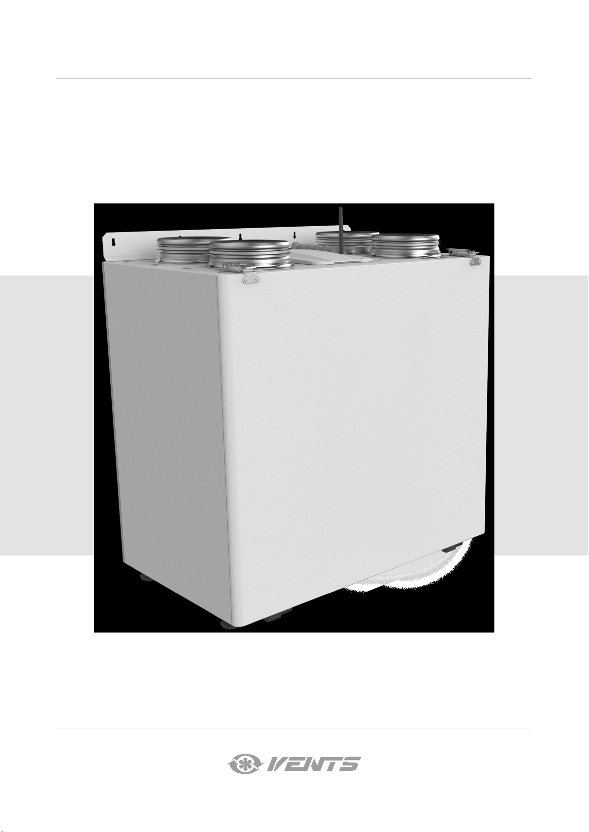
USER’S MANUAL
VUT 160 V EC
VUE 160 V EC
VUT 160 V1 EC
VUE 160 V1 EC
VUT 160 VB EC
VUE 160 VB EC
VUT 160 V1B EC
VUE 160 V1B EC
VUT 350 V1B EC
VUE 350 V1B EC
VUT 350 VB EC
VUE 350 VB EC
VUT 550 VB EC
VUE 550 VB EC
Heat and energy recovery air handling unit
Page 2
VUT/VUE 160/350/550 V(1)(B) EC
CONTENTS
Safety requirements .....................................................................................................................................................................2
Purpose ................................................................................................................................................................................................ 4
Delivery set ........................................................................................................................................................................................ 4
Designation key .............................................................................................................................................................................. 4
Technical data .................................................................................................................................................................................. 5
Design and operating principle ........................................................................................................................................... 7
Installation and set-up................................................................................................................................................................ 9
Connection to power mains .................................................................................................................................................. 13
Technical maintenance .............................................................................................................................................................. 16
Storage and transportation regulations .......................................................................................................................... 17
Manufacturer’s warranty ........................................................................................................................................................... 18
Certificate of acceptance .......................................................................................................................................................... 19
Seller information .......................................................................................................................................................................... 19
Installation certificate .................................................................................................................................................................. 19
Warranty card ...................................................................................................................................................................................19
This user’s manual is a main operating document intended for technical, maintenance, and operating staff.
The manual contains information about purpose, technical details, operating principle, design, and installation of the
VUT/VUE 160/350/550 V(1)(B) EC unit and all its modifications.
Technical and maintenance staff must have theoretical and practical training in the field of ventilation systems and should be able to
perform works in accordance with workplace safety rules as well as construction norms and standards applicable in the territory of the
country.
The information in this user’s manual is correct at the time of the document’s preparation.
The Company reserves the right to modify the technical characteristics, design, or configuration of its products at any time in order to
incorporate the latest technological developments.
No part of this publication may be reproduced, stored in a retrieval system, or transmitted, in any form or by any means in any information
search system or translated into any language in any form without the prior written permission of the Company.
SAFETY REQUIREMENTS
• Please read the user’s manual carefully prior to installing and operating the unit.
• All user’s manual requirements as well as the provisions of all the applicable local and national construction, electrical, and technical
norms and standards must be observed when installing and operating the unit.
• The warnings contained in the user’s manual must be considered most seriously since they contain vital personal safety information.
• Failure to follow the rules and safety precautions noted in this user’s manual may result in an injury or unit damage.
• After a careful reading of the manual, keep it for the entire service life of the unit.
• While transferring the unit control, the user’s manual must be turned over to the receiving operator.
UNIT INSTALLATION AND OPERATION SAFETY PRECAUTIONS
• Disconnect the unit from power mains prior
to any installation operations.
• The unit must be grounded!
• Unpack the unit with care.
• While installing the unit, follow the safety
regulations specific to the use of electric
tools.
2
www.ventilation-system.com
Page 3
VUT/VUE 160/350/550 V(1)(B) EC
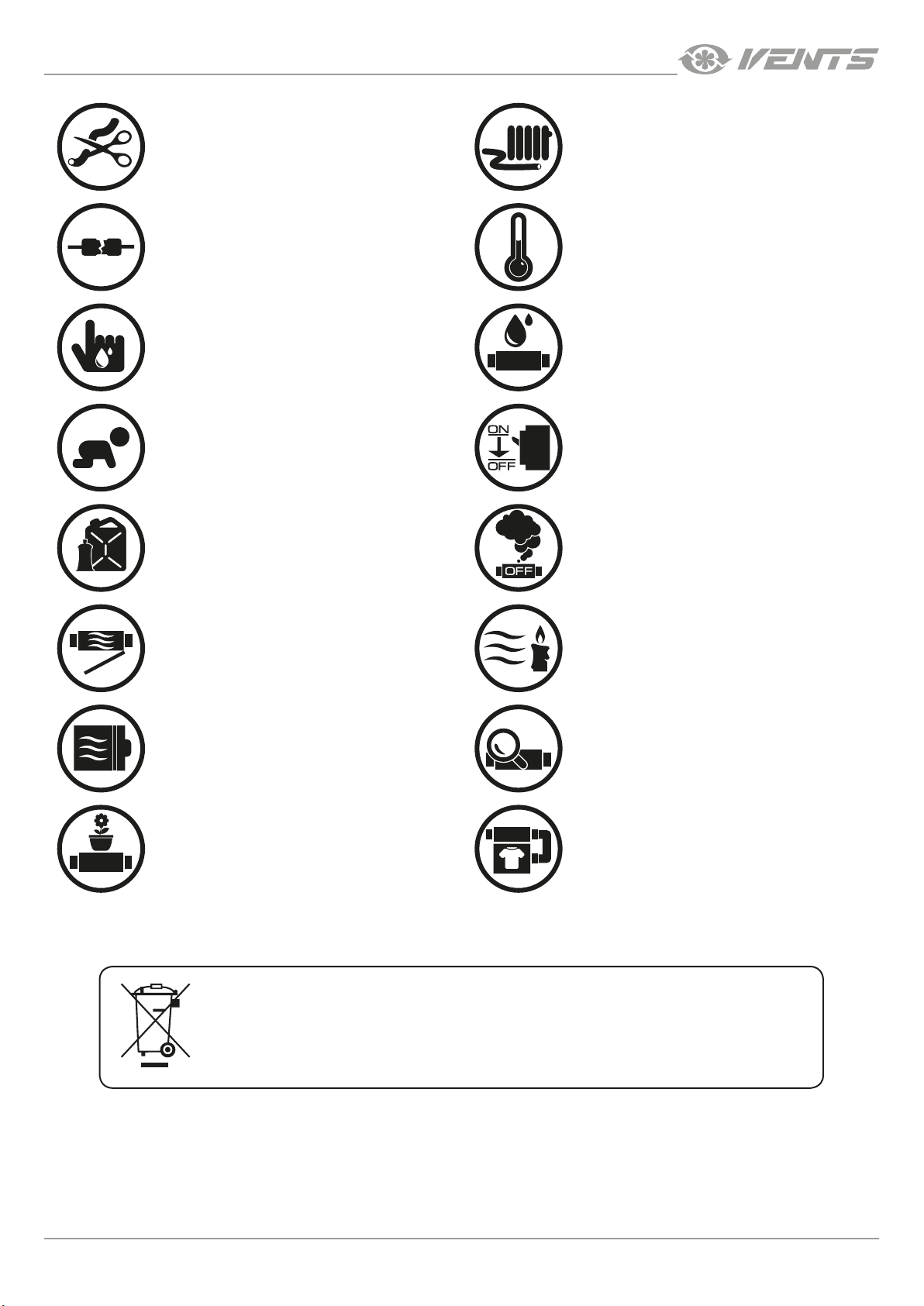
• Do not change the power cable length
at your own discretion. Do not bend the
power cable. Avoid damaging the power
cable. Do not put any foreign objects on the
power cable.
• Do not use damaged equipment or cables
when connecting the unit to power mains.
• Do not lay the power cable of the unit in
close proximity to heating equipment.
• Do not operate the unit outside the
temperature range stated in the user’s
manual. Do not operate the unit in
aggressive or explosive environments.
• Do not touch the unit controls with wet
hands. Do not carry out the installation and
maintenance operations with wet hands.
• Do not allow children to operate the unit.
• Do not store any explosive or highly
flammable substances in close proximity to
the unit.
• Do not open the unit during operation.
• Do not block the air duct when the unit is
switched on.
• Do not wash the unit with water. Protect
the electric parts of the unit against ingress
of water.
• Disconnect the unit from power mains prior
to any technical maintenance.
• When the unit generates unusual sounds,
odour, or emits smoke, disconnect it from
power supply and contact the Seller.
• Do not direct the air flow produced by the
unit towards open flame or ignition sources.
• In case of continuous operation of the unit,
periodically check the security of mounting.
• Do not sit on the unit and avoid placing
foreign objects on it.
THE PRODUCT MUST BE DISPOSED SEPARATELY AT THE END OF ITS SERVICE LIFE.
www.ventilation-system.com
• Use the unit only for its intended purpose.
DO NOT DISPOSE THE UNIT AS UNSORTED MUNICIPAL WASTE.
3
Page 4
VUT/VUE 160/350/550 V(1)(B) EC
PURPOSE
The unit is designed to ensure continuous mechanical air exchange in houses, offices, hotels, cafés, conference halls, and other utility
and public spaces as well as to recover the heat energy contained in the air extracted from the premises to warm up the filtered stream
of supply air.
The unit is not intended for organizing ventilation in swimming pools, saunas, greenhouses, summer gardens and other spaces with high
humidity.
Due to the ability to save heating energy by means of energy recovery, the unit is an important element of energy-efficient premises.
The unit is a component part and is not designed for stand-alone operation.
It is rated for continuous operation.
Transported air must not contain any flammable or explosive mixtures, evaporation of chemicals, sticky substances, fibrous materials,
coarse dust, soot and oil particles or environments favourable for the formation of hazardous substances (toxic substances, dust,
pathogenic germs).
Relative humidity of transported air must not exceed +20 °C at an ambient humidity of 80 %.
THE UNIT SHOULD NOT BE OPERATED BY CHILDREN OR PERSONS WITH REDUCED
PHYSICAL, MENTAL, OR SENSORY CAPACITIES, OR THOSE WITHOUT
THE APPROPRIATE TRAINING.
THE UNIT MUST BE INSTALLED AND CONNECTED ONLY BY PROPERLY QUALIFIED
PERSONNEL AFTER THE APPROPRIATE BRIEFING.
THE CHOICE OF UNIT INSTALLATION LOCATION MUST PREVENT UNAUTHORIZED
ACCESS BY UNATTENDED CHILDREN.
DELIVERY SET
Name Number
Air handling unit 1 pc.
User's manual 1 pc.
Packing box 1 pc.
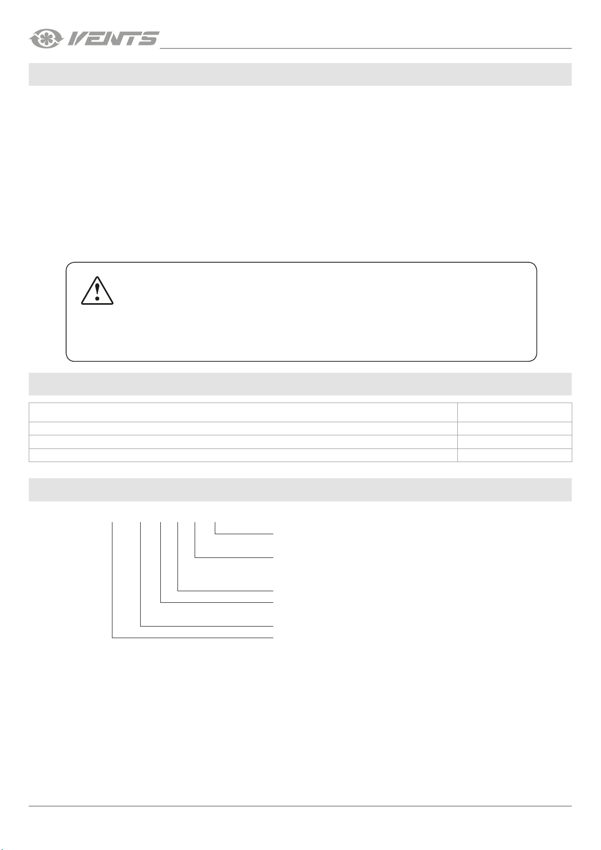
DESIGNATION KEY
VUT 350 V 1 B EC
Motor type
EC — electronically commutated
Additional components
_ — no
B – bypass
Casing design
Spigot orientation
V — vertical
Rated air ow [m
Series of units
VUT — heat recovery air handling unit
VUE — energy recovery air handling unit
3
/h]
4
www.ventilation-system.com
Page 5
VUT/VUE 160/350/550 V(1)(B) EC
TECHNICAL DATA
The unit is designed for indoor application with the ambient temperature ranging from +1 °C up to +40 °C and relative humidity up to
80 %.
In order to prevent condensation on the internal walls of the units, it is necessary that the surface temperature of the casing is 2-3 °C
higher than the dew point temperature of the transported air.
The unit is rated as a Class I electrical appliance.
Hazardous parts access and water ingress protection rating:
• IP22 for the unit connected to the air ducts
• IP44 for the unit motors
The unit design is constantly being improved, thus some models may be slightly different from those described in this manual.
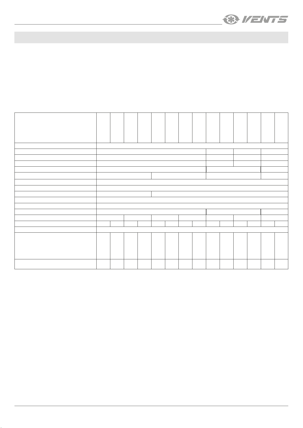
TECHNICAL DATA
MODEL
VUT 160 V EC
VUE 160 V EC
VUT 160 VB EC
VUE 160 VB EC
VUT 160 V1 EC
VUE 160 V1 EC
VUT 160 V1B EC
VUE 160 V1B EC
VUT 350 V1B EC
VUE 350 V1B EC
VUT 350 VB EC
VUE 350 VB EC
VUT 550 VB EC
Supply voltage [V/50 (60) Hz] 1~ 220-240
Maximum fan power [W ] 57 169 178 337
Maximum unit current (without a heater) [A] 0.5 1.3 1.4 2.4
Maximum air flow [m
RPM [min
Sound pressure level at 3 m distance [dBA] 24 22 28 26
Transported air temperature [°С] -25...+40
Casing material Painted steel
Insulation, mineral wool [mm] 20 40
Filtering class of the extract filter G4
Filtering class of the supply filter F7 (optionally G4)
Connected air duct diameter [mm] 125 160 200
Weight [kg] 34 36 42 44 57 64 82
Heat recovery efficiency [%] 85-93 76-92 85-93 76-92 85-93 76-92 85-93 76-92 85-92 73-91 85-92 73-91 84-92 73-91
Heat exchanger type Counter-flow
-1
] 3770 3200 2860
3
/h] 200 420 450 690
VUE 550 VB EC
Heat exchanger material
Polystyrene
Enthalpy
membrane
Polystyrene
Enthalpy
membrane
Polystyrene
Enthalpy
membrane
Polystyrene
Enthalpy
membrane
Polystyrene
Enthalpy
membrane
Polystyrene
Enthalpy
membrane
Polystyrene
SEC class A+ A A+ A A+ A A+ A A+ A A+ A A+ A
The VUE units are equipped with an enthalpy heat exchanger and do not require condensate drainage.
Enthalpy
membrane
www.ventilation-system.com
5
Page 6
B
B1
L2
VUT/VUE 160/350/550 V(1)(B) EC
ØD
L1
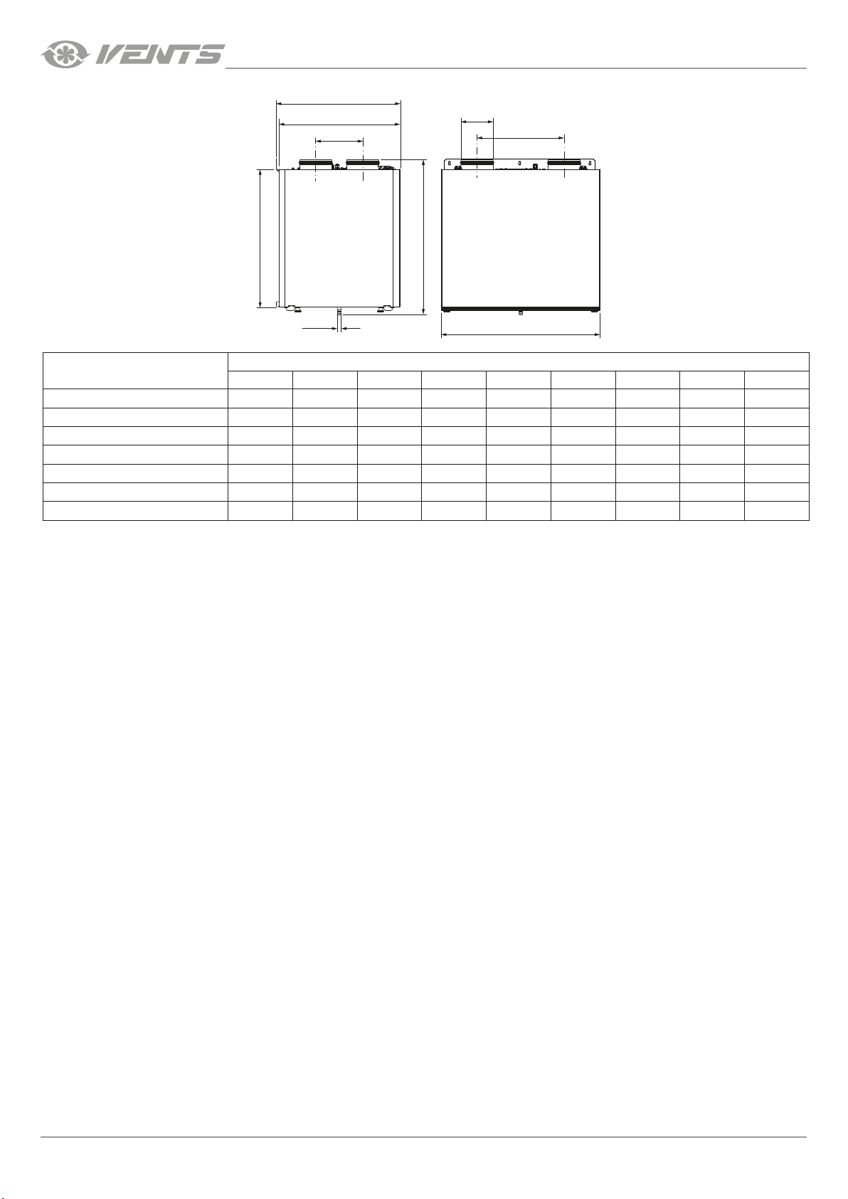
Model
VUT/VUE 160 V EC
VUT/VUE 160 V1 EC
VUT/VUE 160 VB EC
VUT/VUE 160 V1B EC
VUT/VUE 350 VB EC
VUT/VUE 350 V1B EC
VUT/VUE 550 VB EC
H1
ØD1
H
L
Dimensions [mm]
Ø D Ø D1 B B1 H H1 L L1 L2
125 18 340 330 665 550 600 388 143
125 18 380 370 690 590 640 388 143
125 18 340 330 665 580 600 388 143
125 18 380 370 710 620 640 388 143
160 18 600 583 760 675 730 426 230
160 18 480 470 760 675 730 426 200
200 18 730 720 76 0 675 823 498 288
6
www.ventilation-system.com
Page 7
VUT/VUE 160/350/550 V(1)(B) EC
DESIGN AND OPERATING PRINCIPLE
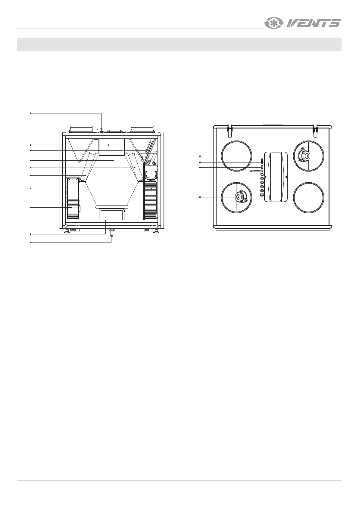
The unit has the following operating principle: warm stale extract air from the room flows into the unit where it is filtered by the extract
filter, then air flows through the heat exchanger and is exhausted outside by the extract fan. Cold fresh air from the outside flows into
the unit, where it is cleaned by the supply filter. Then the air flows through the heat exchanger and is directed to the room with the
supply fan. Heat energy of warm extract air is transferred to clean intake fresh air from the outside and warms it up. The air flows are fully
separated while flowing through the heat exchanger. Heat recovery minimizes heat losses, which reduces the cost of space heating in
the cold season.
UNIT DESIGN
1
2
3
4
5
6
7
11
12
13
14
8
9
10
1 – cable glands; 2 – control unit; 3 – bypass damper (except VUT/VUE 160 V(1) EC models); 4 – counter-flow heat exchanger; 5 – extract
filter; 6 – supply filter; 7 – supply fan; 8 – extract fan; 9 – drain pan; 10 – drain pipe; 11 – extract filter differential pressure switch (only for
the VUT/VUE 550 VB EC A21 units); 12 – NKP duct electric preheater connector; 13 – NKD duct electric reheater connector; 14 – supply
filter differential pressure switch (only for the VUT/VUE 550 VB EC A21 units).
The air handling unit is equipped with a hinged front service panel for repair and maintenance operations. The removable service panel
design enables to change the service side location. The control unit is accessible for installation and wiring operations through the
inspection door on top of the unit. The power cable and ground cable are connected to the control unit via the cable glands.
The bypass damper is open or closed depending on operation mode of the unit.
The VUT/VUE 550 VB EC units are equipped with differential pressure switches for filter contamination control. Access to the pressure
switches is provided through the inlet and outlet spigots.
The difference between the supply and extract air flow temperature leads to condensate generation in the VUT 160/350/550 V(1)B EC
units. Condensate is collected in the drain pan and is removed outside through the drain pipe.
The VUE 160/350/550 V(1)B EC units are equipped with a heat exchanger with an enthalpy membrane and do not require condensate
drainage.
Accessories for the unit are available on a separate order.
• The HV2 humidity sensor is connected to the terminal block, the HR-S humidity sensor is connected to the controller. The unit
with an installed humidity sensor maintains a set indoor humidity point. As the extract air humidity rises above the set point, the
system automatically switches to the maximum speed. As the humidity drops down below the set point the unit returns to the
previous mode.
• CO2 sensor (connected to the controller). Designed for indoor carbon dioxide concentration measurement and respective air
capacity regulation through the control output signal to the fan.
• VOC sensor (connected to the controller). Qualitative assessment of air saturation with contaminants (cigarette smoke, exhaled air,
solvent and detergent vapours).The sensor sensitivity can be adjusted with regards to the expected maximum level of air pollution.
Enables on-demand ventilation which results in considerable energy savings as air is exchanged only upon reaching the preset
level of pollution.
• NKP duct preheater (for the VUT/VUE 160/350/550 V(1) (B) EC A21 units). The heater maintains the duct air temperature at a point
that prevents the heat exchanger freezing. Heater installation and connection to the unit are described in the heater user’s manual.
• NKD duct reheater (for the VUT/VUE 160/350/550 V(1) (B) EC A21 units). The heater maintains a room temperature set by the
temperature sensor. Heater installation and connection to the unit are described in the heater user’s manual.
www.ventilation-system.com
7
Page 8
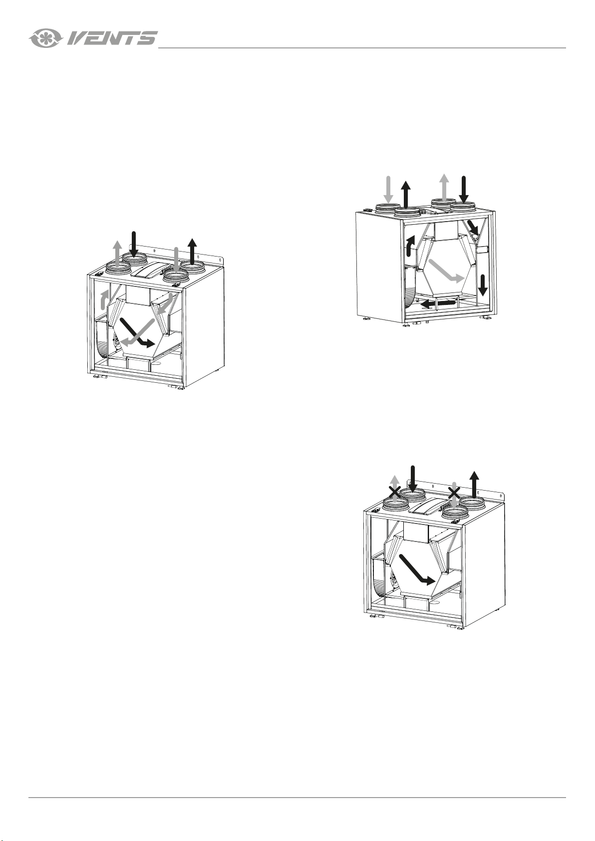
UNIT OPERATION MODES
Heat Recovery mode Summer Cooling mode
Warm extract air from the room flows into the unit and is cleaned in
the extract filter. Then the air is moved through the heat exchangers
and is exhausted outside with the extract fan. Cold fresh air from
outside flows into the unit, where it is cleaned in the supply filter.
The bypass damper is opened, the extract air that is removed from
the premises is routed along the bypass duct and does not come in
contact with the heat exchanger. The temperature of the air is not
changed after passing through the heat exchanger.
Then the air flows through the heat exchanger and is directed to
the room with the supply fan.
INTAKE AIR
Heat is exchanged between the intake and extract air in the heat
exchanger. The air flows are fully separated while flowing through
the heat exchanger. Heat recovery minimizes heat losses, which
reduces the cost of space heating in the cold season.
EXTRACT AIR
SUPPLY AIR
INTAKE AIR
EXHAUST AIR
VUT/VUE 160/350/550 V(1)(B) EC
SUPPLY AIR
EXHAUST AIR
EXTRACT AIR
Back side view
Service side view
Heat exchanger freeze protection (frost danger appears when the extract air temperature downstream of the heat exchanger is lower
than +5 °C and intake air temperature upstream of the heat exchanger is lower than -3 °C for units with preheating and +3 °C for units
without preheating).
In case of freezing danger the supply fan is turned off in the VUT/
VUE 160/350/550 V(1) (B) EC A14 units.
When the temperature increases, the unit returns to the previous
EXTRACT AIR
SUPPLY AIR
EXHAUST AIR
INTAKE AIR
operation mode.
There are three freeze protection modes for the VUT/VUE 160/350/550 V(1) (B) EC A21 units:
• gradual speed reduction of the supply fan
• with the help of a bypass
• with the help of electric preheating of air (if the unit is equipped with a duct preheater)
Mode selection and settings are described in the A21 control system user’s manual.
8
Service side view
www.ventilation-system.com
Page 9
VUT/VUE 160/350/550 V(1)(B) EC
~100 mm
INSTALLATION AND SETUP
READ THE USER'S MANUAL BEFORE INSTALLING THE UNIT
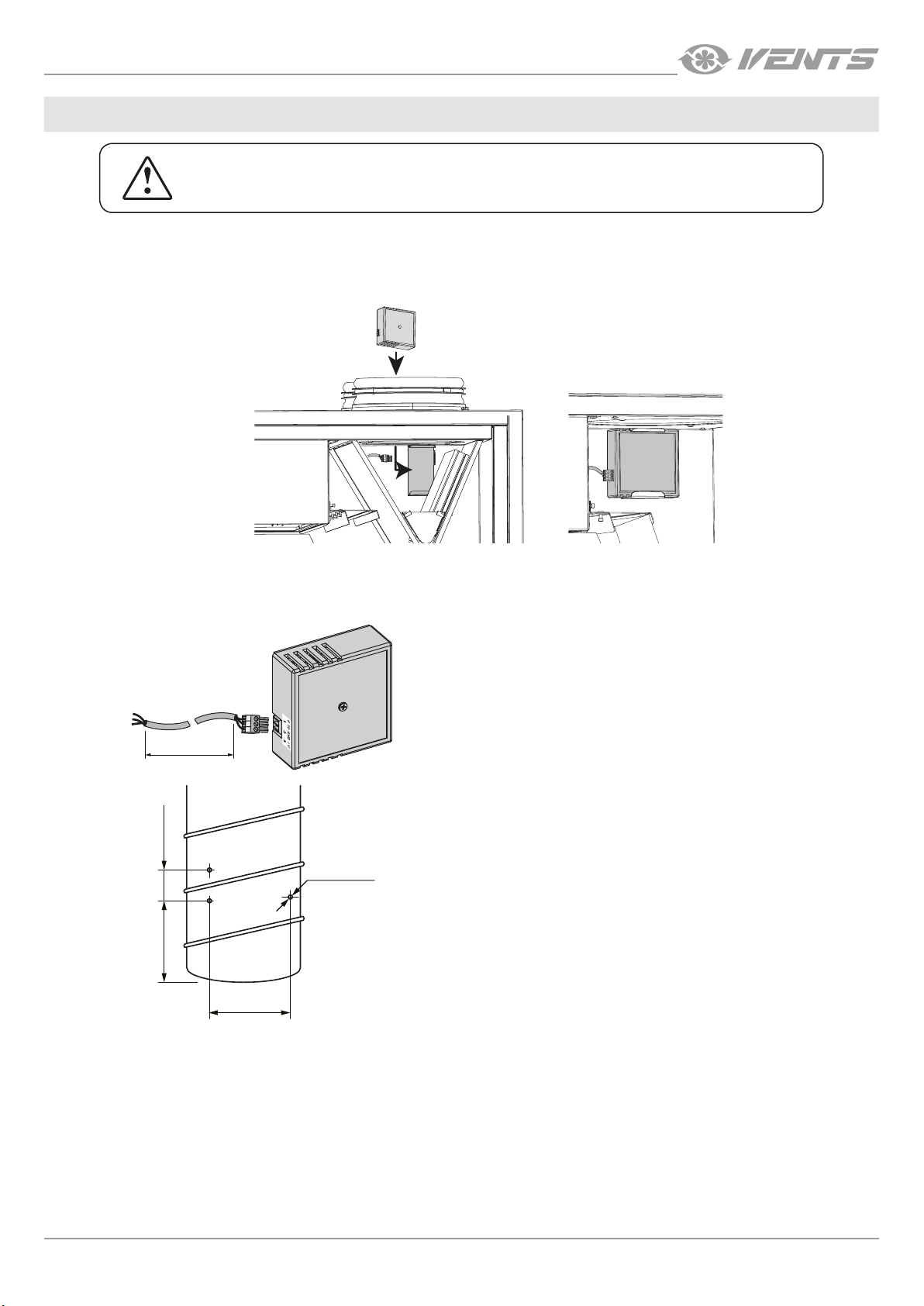
HV2 HUMIDITY SENSOR INSTALLATION AND CONNECTION FOR THE VUT/VUE 350/550 V1 B EC UNITS
The sensor is installed before the unit mounting. Install the humidity sensor through the outlet spigot into the mount located on the wall of the exhaust
air duct. Connect the humidity sensor connector to the respective connector with the cable from the control unit. Connector with the cable from the
control unit is installed by the manufacturer.
1
2
3
1
2
3
HV2 HUMIDITY SENSOR INSTALLATION AND CONNECTION FOR THE VUT/VUE 160 V1 B EC UNITS
The sensor is installed in the exhaust air duct prior to mounting the unit and the air ducts.
To connect the sensor to the unit, use a cable with a connector
that is included in the delivery set of the unit.
1
2
3
2 m
Prepare holes for mounting the sensor and for cable outlet.
~30 mm
Ø 6 mm
3 holes
~100 mm
www.ventilation-system.com
9
Page 10
VUT/VUE 160/350/550 V(1)(B) EC
EXTRACT AIR
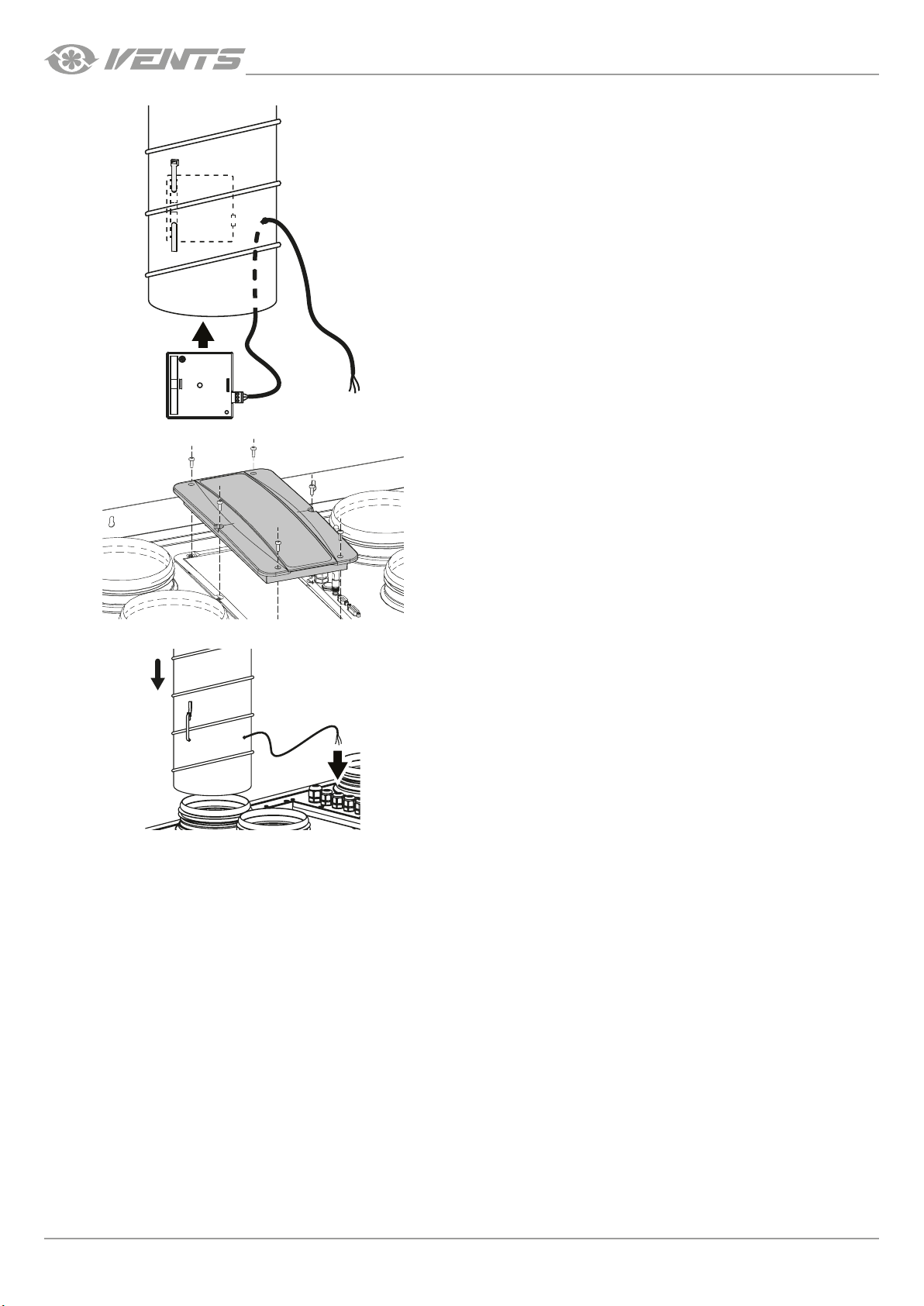
Secure the sensor with a clip on the inner side of the duct and pull
the cable through the hole in the duct.
Seal connections using sealant or other materials.
To access the control unit, remove the fixing screws and remove the
cover.
Pull the cable into the unit through the cable gland and connect it
to the terminal block according to the wiring diagram of external
devices.
10
www.ventilation-system.com
Page 11
VUT/VUE 160/350/550 V(1)(B) EC
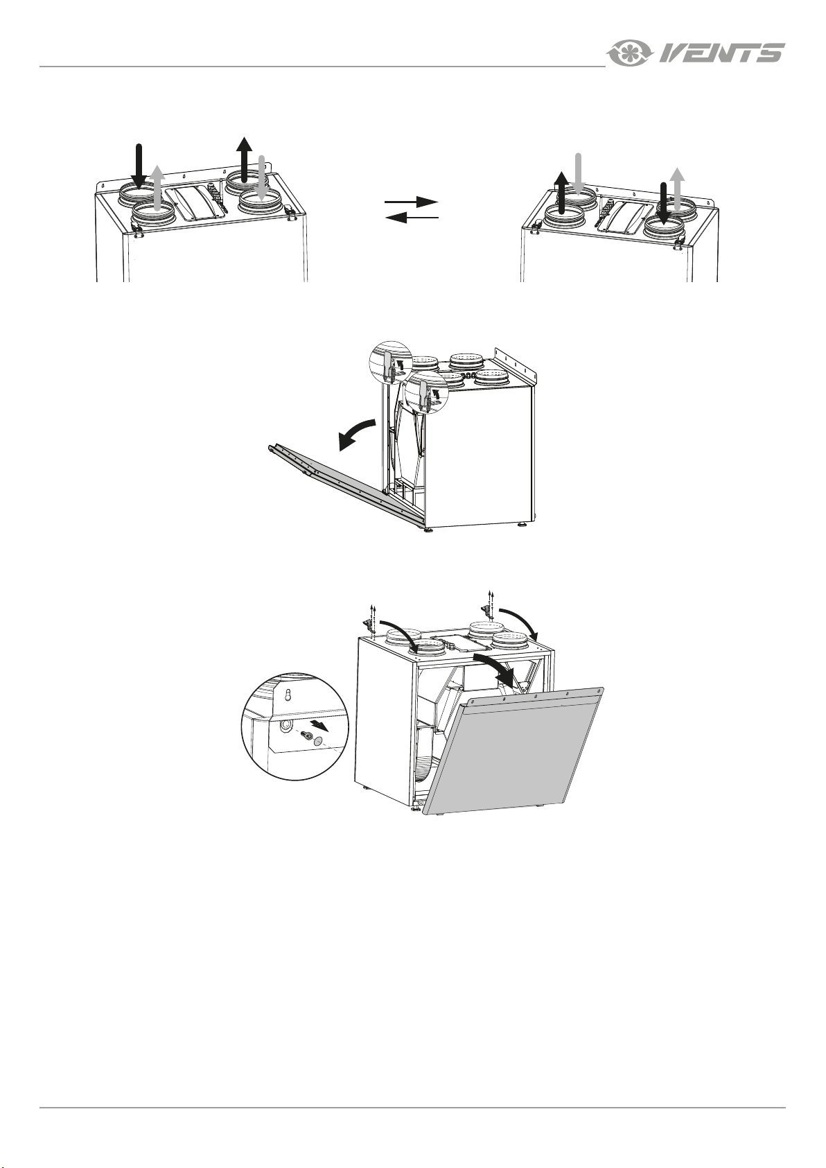
The unit design allows changing the service side.
EXTRACT AIR
EXHAUST AIR
INTAKE AIR
SUPPLY AIR
SERVICE SIDE CHANGE
INTAKE AIR
EXHAUST AIR
EXTRACT AIR
SUPPLY AIR
Left hand service side
Right hand service side
Release the latches, disconnect the ground cable and remove the service panel.
Remove the latches and move them to the opposite side. Remove the back panel by undoing the three screws hidden under plastic
plugs.
Install the back panel.
www.ventilation-system.com
11
Page 12
VUT/VUE 160/350/550 V(1)(B) EC
4
UNIT INSTALLATION
To get the best performance of the unit and to minimize turbulence-induced air pressure losses, connect the straight air duct section to
the spigots on both sides of the unit while installing.
Minimum straight air duct length:
• equal to 1 air duct diameter on the intake side
• equal to 3 air duct diameter on the outlet side
If the air ducts are too short or not connected, protect the unit parts from ingress of foreign objects. To prevent uncontrollable access to
the fans, the spigots may be covered with a protecting grille or other protecting device with mesh width not more than 12.5 mm.
When selecting the unit mounting position, enable free excess to the service panel for maintenance and service operations.
The unit should be mounted strictly horizontally in the longitudinal and transverse planes. In case of non-compliance, unit’s casing
distortion and operation disturbance will occur.
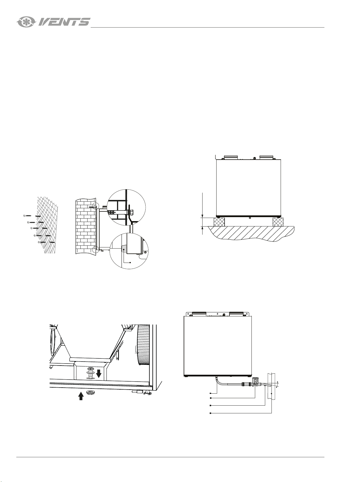
Unit wall mounting Unit oor mounting
Fasteners for wall mounting are not included in the delivery set
and should be ordered separately.
While choosing fasteners consider the material of the mounting
surface as well as the weigh of the unit, refer to the “Technical data”
section. Fasteners for unit mounting should be selected by the
installation specialist.
Install the fasteners in the wall. Suspend the unit on fasteners.
Achieve a strictly vertical position of the unit by rotating the
adjustable stop (1).
Install the unit on the pre-mounted floor supports, minimum 150
mm height, to ensure sufficient access for the drain pipe connection
to the U-trap and for condensate drain system installation.
min 150 mm
1
CONDENSATE DRAINAGE
Condensate drainage is required for the VUT V(1)B EC unit series.
The hole for the drain pipe is at the bottom of the unit. Remove the plug from the hole. Open the service panel and remove the plug in
the drain pan. Install the drain pipe from the delivery set into the hole, then connect the drain pipe to the sewage system using the SG-32
U-trap kit (available upon separate order). Make sure the U-trap is always filled with water. The pipe slope downwards must be at least 3°.
1 – drain pipe; 2 – U-trap; 3 – drain hose; 4 – sewage system
12
min 3°
1
2
3
www.ventilation-system.com
Page 13
VUT/VUE 160/350/550 V(1)(B) EC
CONNECTION TO POWER MAINS
DISCONNECT THE UNIT FROM POWER MAINS PRIOR TO ANY OPERATIONS.
THE UNIT MUST BE CONNECTED TO POWER SUPPLY BY A QUALIFIED ELECTRICIAN.
THE RATED ELECTRICAL PARAMETERS OF THE UNIT ARE GIVEN ON THE
MANUFACTURER’S LABEL.
ANY TAMPERING WITH THE INTERNAL CONNECTIONS IS PROHIBITED
AND WILL VOID THE WARRANTY.
• The unit is rated for connection to 1~220-240 V/50 (60) Hz power mains.
• The unit must be connected to power mains using insulated electric conductors (cables, wires). The actual wire cross section
selection must be based on the maximum load current, maximum conductor temperature depending on the wire type, insulation,
length and installation method.
• The external power input must be equipped with an automatic circuit breaker built into the stationary wiring to open the electric
circuit in case of overload or short-circuit. The circuit breaker installation place must provide quick access for emergency shutdown
of the unit. The trip current of the automatic circuit breaker QF must exceed the maximum current consumption of the unit (refer
to the technical data table). The recommended trip current of the circuit breaker is the next current in the standard trip current row
following the maximum current of the connected unit. The automatic circuit breaker is not included in the delivery set.
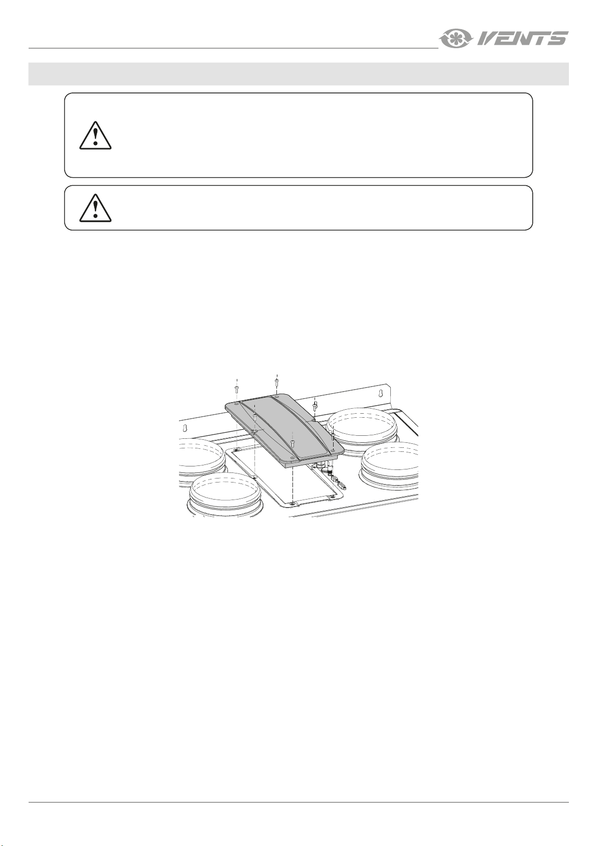
To access the control unit, remove the fixing screws and remove the cover. The terminal block and the controller for external devices
connection are located in the control unit.
www.ventilation-system.com
13
Page 14
VUT/VUE 160/350/550 V(1)(B) EC
Power input
230 VAC
Power input
230 VAC
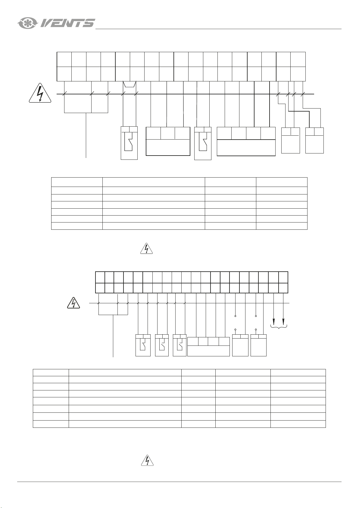
EXTERNAL WIRING DIAGRAM FOR THE VUT/VUE 160/350/550 V1B EC A14 UNITS
GND
L N C
PE PK PK +U
0-10V
NO
GND
Tx
Х1
1 2 3 4 5 6 7 8 9 10 11 12 13 14 15 16 17
Remove
the jumper
Brown
White
Green
2 1
+U
GND
0-10V
HV2*
PK1*
Designation Name Model Wire**
SM1* Supply air damper actuator 2 x 0.75 mm
SM2* Extract air damper actuator 2 x 0.75 mm
РК1* Contact from fire alarm panel NC 2 x 0.75 mm
С02* CO2 sensor NO 2 x 0.75 mm
HV2* Humidity sensor 3 x 0.75 mm
P1 External control panel 4 x 0.25 mm
*Is not included in the delivery set.
** Maximum connecting cable length is 20 m!
— ELECTRIC SHOCK HAZARD!
1 2
GND
CO2*
White
P1
Brown
Tx
Rx
Green
Rx
SM-L SM-N
+U
Yellow
+U
2
2
2
2
2
2
2 1
L N L N
2 1
SM1* SM2*
EXTERNAL CONNECTIONS DIAGRAM FOR THE VUT/VUE 160 V1 B EC A21 UNITS
Kamin*
C
GND
Green
GND
P1*
L
SQ
X1
Designation Name Model Wire*** Note
SM1* Supply air damper actuator NO 2 x 0.75 mm
SM2* Extract air damper actuator NO 2 x 0.75 mm
РК1* Contact from fire alarm panel NC 2 x 0.75 mm
CCU* CCU control NO 2 x 0.75 mm
P1* External control panel 4 x 0.25 mm
Boost* On/Off contacts for the Boost mode NO 2 x 0.75 mm
Kamin* On/Off contacts of the Kamin mode NO 2 x 0.75 mm
*Is not included in the delivery set.
** The U supply voltage of the SM1, SM2 external dampers is selected depending on the type of dampers.
*** Maximum connecting cable length is 20 m!
Output parameters: terminals 19-24 - 3A, 30VDC / ~ 250 VAC (“dry contact”).
1 2 3 4 9 10 11 12 13 14 15 16 17 18 19 20 21 22 23 24
PEN
NO NO
12
12 12 12 12 12
PK1 *
— ELECTRIC SHOCK HAZARD!
NO
C C
Boost*
A BNC C
Brown
А
+24V
Yellow
White
В
+24V
NOCNO
U**U**
12 12
12
SM1*12SM2*
2
2
2
2
2
2
2
C
CCU*
3A, 30DC/~250 AC
3A, 30DC/~250 AC
3A, 30DC/~250 AC
14
www.ventilation-system.com
Page 15
VUT/VUE 160/350/550 V(1)(B) EC
Power input
230 VAC
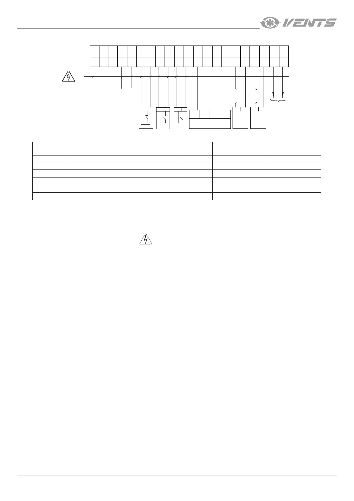
EXTERNAL CONNECTIONS DIAGRAM FOR THE VUT/VUE 350/550 V1 B EC A21 UNITS
GND
Green
X1
L
SQ
N PEL
NC
NO
NO NO
C
1 2 3 4 5 6 7 8 9 10 11 12 13 14 15 16 17 18 19 20 21
12
12
12 12 12 12
GND
PK1 *
Boost*
Designation Name Model Wire*** Note
SM1* Supply air damper actuator NO 2 x 0.75 mm
SM2* Extract air damper actuator NO 2 x 0.75 mm
РК1* Contact from fire alarm panel NC 2 x 0.75 mm
CCU* CCU control NO 2 x 0.75 mm
P1* External control panel 4 x 0.25 mm
Boost On/Off contacts for the Boost mode NO 2 x 0.75 mm
Kamin On/Off contacts of the Kamin mode NO 2 x 0.75 mm
*Is not included in the delivery set.
** The U supply voltage of the SM1, SM2 external dampers is selected depending on the type of dampers.
*** Maximum connecting cable length is 20 m!
Kamin*
P1*
Output parameters: terminals 16-21 - 3A, 30VDC / ~ 250 VAC («dry contact»).
+24V
A BC C C C
NOCNO
U**U**
Brown
Yellow
White
А
В
+24V
12 12
12
SM1*12SM2*
2
2
2
2
2
2
2
CCU*
3A, 30VDC/~250 AC
3A, 30VDC/~250 AC
3A, 30VDC/~250 AC
— ELECTRIC SHOCK HAZARD!
www.ventilation-system.com
15
Page 16
VUT/VUE 160/350/550 V(1)(B) EC
TECHNICAL MAINTENANCE
DISCONNECT THE UNIT FROM POWER SUPPLY BEFORE
ANY MAINTENANCE OPERATIONS!
Maintenance operations of the unit are required 3-4 times per year. They include general cleaning of the unit and the following operations:
1. Filter maintenance (3-4 times per year).
Dirty filters increase air resistance in the system and reduce supply air volume. The filters require cleaning not less than 3-4 times per year.
Clean the filter with a vacuum cleaner or replace it with a new one. For new filters contact the Seller.
2. Heat exchanger maintenance (once per year).
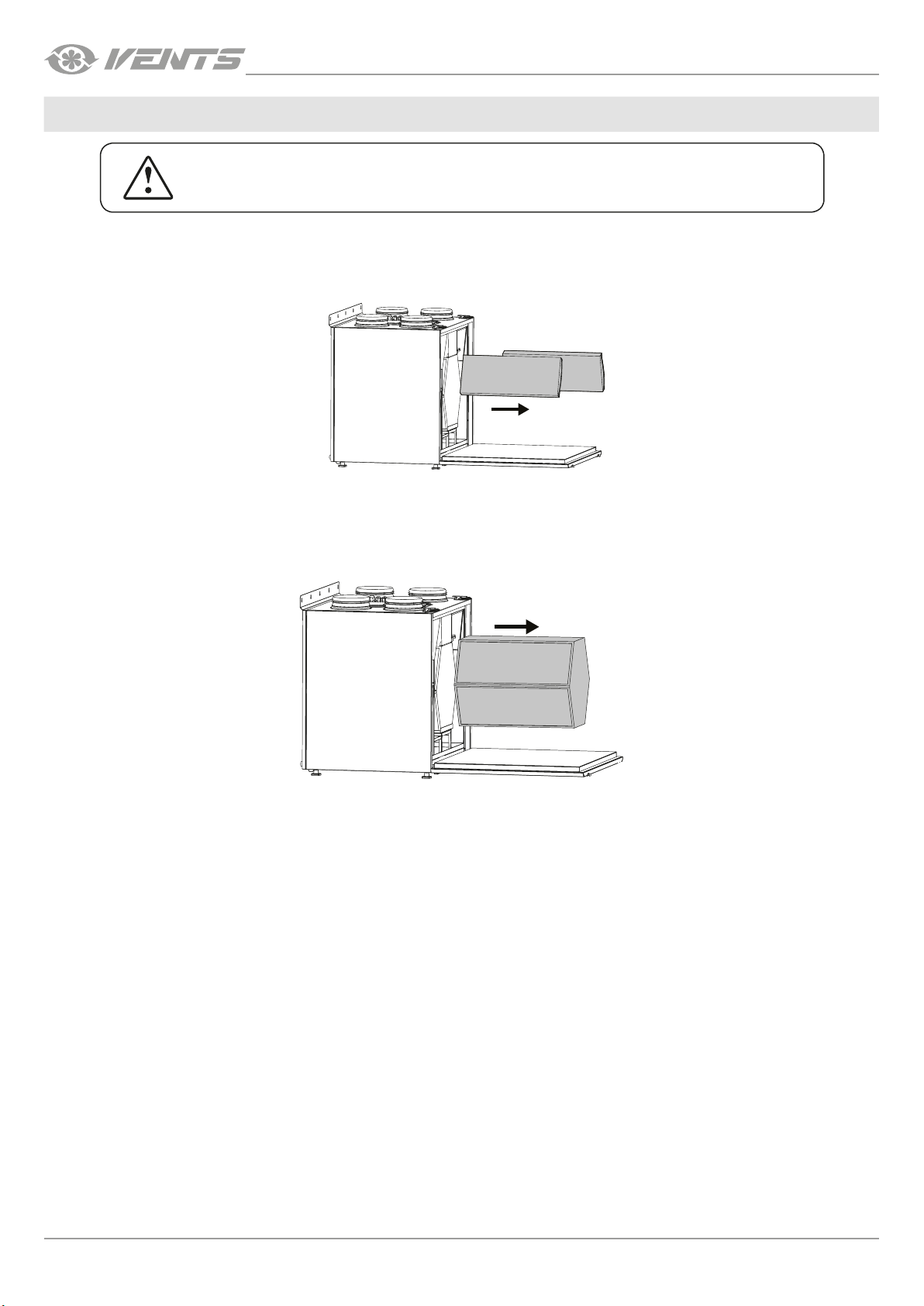
Some dust may accumulate on the heat exchanger even in case of regular maintenance of the filters. To maintain the high heat recovery
efficiency, regular cleaning is required. To clean the heat exchanger, remove it from the unit and clean the heat exchanger by using
compressed air or a vacuum cleaner. In case of severe contamination, the heat exchanger can be washed with water. After cleaning, reinstall the heat exchanger into the unit.
3. Fan maintenance (once per year).
Even in case of regular maintenance of the filters, some dust may accumulate inside the fans and reduce the fan performance and supply
air flow. Fans should be cleaned by the service technician.
4. Condensate drainage system maintenance (4 times per year).
The condensate drainage (drain line) may get clogged by dirt and dust particles contained in the exhaust air. Check the drain line
operation by filling the drain pan under the unit with water, clean the U-trap and the drain line, if necessary.
5. Supply air ow control (twice per year).
The supply duct grille may get clogged with leaves and other objects reducing the unit performance and supply air delivery. Check the
supply grille twice per year and clean it as required.
6. Ductwork system maintenance (once in 5 years).
Even regular fulfilling of all the maintenance operations prescribed above may not completely prevent dirt accumulation in the air ducts,
which leads to air pollution and reduces the unit capacity. Duct maintenance means regular cleaning or replacement.
16
www.ventilation-system.com
Page 17
VUT/VUE 160/350/550 V(1)(B) EC
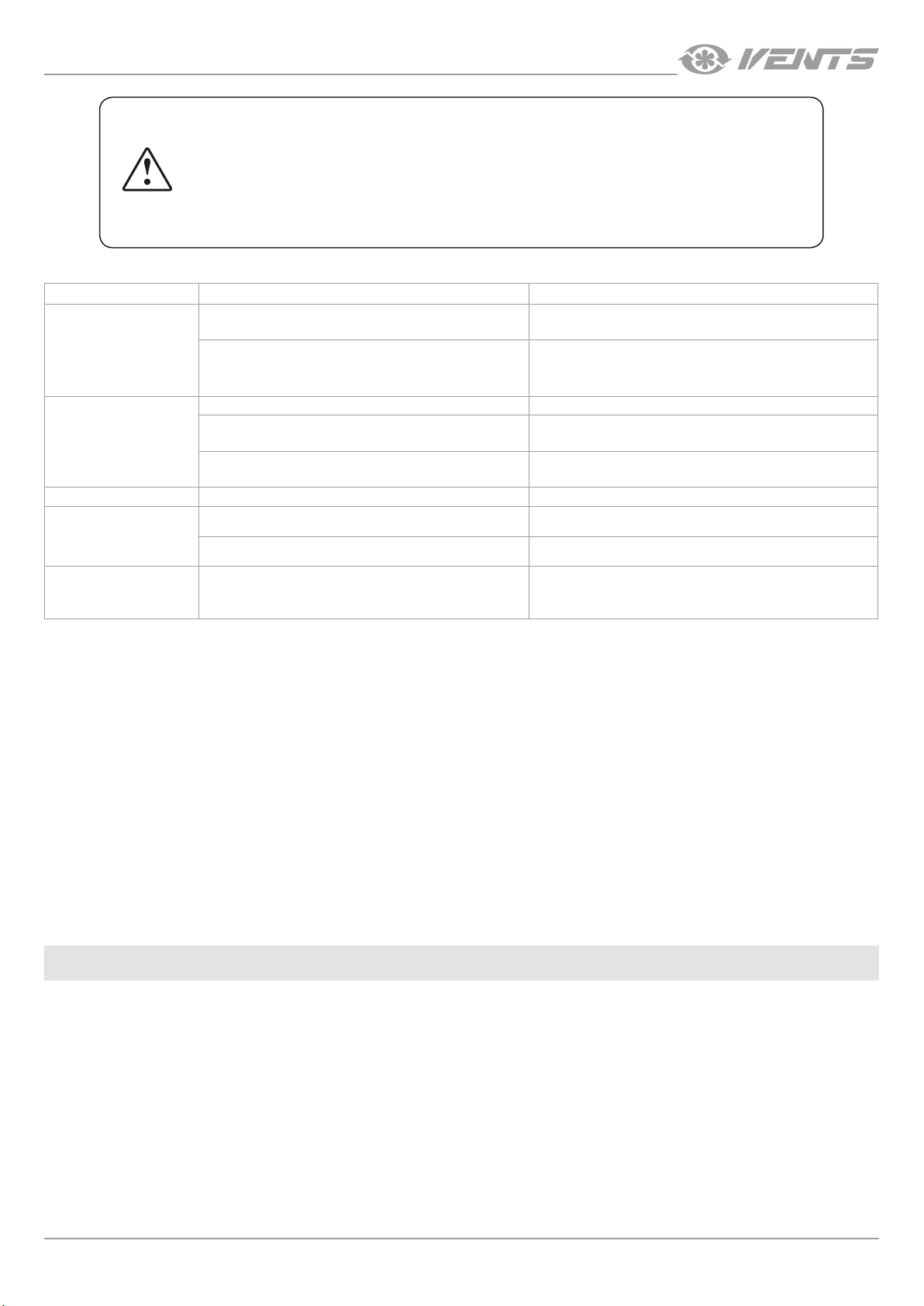
IF UNIDENTIFIED NOISES OR ODOURS SHOULD ARISE AND IN CASE OF DEFORMATION
OF ELEMENTS, VIBRATION, TERMINATION OF AIR SUPPLY/EXTRACTION OR REDUCED
SYSTEM PERFORMANCE, IMMEDIATELY DISCONNECT THE UNIT FROM POWER SUPPLY
AND CONTACT THE SELLER FOR THE VENTILATION SYSTEM DIAGNOSTICS.
DIAGNOSTICS MUST BE CARRIED OUT BY QUALIFIED SPECIALISTS.
POSSIBLE REASONS AND TROUBLESHOOTING
Problem Possible reasons Troubleshooting
No power supply.
The fan(s) does not start
when the unit is on.
Low air flow.
Cold supply air. The extract filter is soiled. Clean or replace the extract filter.
Noise, vibration.
Water leakage
(only for the VUT VB EC units)
The mode in which the fans are turned off is set. Change the mode with the help of the control panel.
Low set fan speed. Set higher speed.
The filters and the fans are clogged, the heat exchanger
is clogged.
Ventilation system elements (air ducts, diffusers, louver
shutters, grilles) are clogged, damaged or closed.
The fan or casing screw connection is loose. Tighten the screw connection of the fans or the casing.
No anti-vibration connectors on air duct pipe flanges. Install anti-vibration connectors.
The drainage system is soiled, damaged, or installed
incorrectly.
Make sure the power supply line is connected correctly,
otherwise troubleshoot the connection error.
Clean or replace the filters, clean the fans and the heat
exchanger.
Clean or replace the ventilation system elements, such as air
ducts, diffusers, louvre shutters, grilles.
Clean the drain line. Check the drain line slope angle. Make
sure that the U-trap is filled with water and the drain pipes
are frost protected.
If troubleshooting steps have failed, contact the Seller of the product.
In case of faults not described in the table, contact the Seller for further information.
STORAGE AND TRANSPORTATION REGULATIONS
• Store the unit in the manufacturer’s original packaging box in a dry closed ventilated premise with temperature range +5 ˚...+40 ˚С
and relative humidity up to 70 %.
• Storage environment must not contain aggressive vapours and chemical mixtures provoking corrosion, insulation, and sealing
deformation.
• Use suitable hoist machinery for handling and storage operations to prevent possible damage to the unit.
• Follow the handling requirements applicable for the particular type of cargo.
• The unit can be carried in the original packaging by any mode of transport provided proper protection against precipitation and
mechanical damage. The unit must be transported only in the working position.
• Avoid sharp blows, scratches, or rough handling during loading and unloading.
• Prior to the initial power-up after transportation at low temperatures allow the unit to warm up at room temperature for at least 3-4
hours.
www.ventilation-system.com
17
Page 18
VUT/VUE 160/350/550 V(1)(B) EC
MANUFACTURER’S WARRANTY
The product is in compliance with EU norms and standards on low voltage guidelines and electromagnetic compatibility. We hereby
declare that the product complies with the provisions of Electromagnetic Council Directive 2014/30/EU, Low Voltage Directive 2014/35/
EU and CE-marking Directive 93/68/EEC. This certificate is issued following test carried out on samples of the product referred to above.
The manufacturer hereby warrants normal operation of the unit for 24 months after the retail sale date provided the user's observance
of the transportation, storage, installation, and operation regulations. Should any malfunctions occur in the course of the unit operation
through the Manufacturer's fault during the guaranteed period of operation, the user is entitled to get all the faults eliminated by the
manufacturer by means of warranty repair at the factory free of charge. The warranty repair includes work specific to elimination of faults
in the unit operation to ensure its intended use by the user within the guaranteed period of operation. The faults are eliminated by means
of replacement or repair of the unit components or a specific part of such unit component.
The warranty repair does not include:
• routine technical maintenance
• unit installation/dismantling
• unit setup
To benefit from warranty repair, the user must provide the unit, the user's manual with the purchase date stamp, and the payment
paperwork certifying the purchase. The unit model must comply with the one stated in the user’s manual. Contact the Seller for warranty
service.
The manufacturer’s warranty does not apply to the following cases:
• User’s failure to submit the unit with the entire delivery package as stated in the user’s manual including submission with missing
component parts previously dismounted by the user.
• Mismatch of the unit model and the brand name with the information stated on the unit packaging and in the user's manual.
• User’s failure to ensure timely technical maintenance of the unit.
• External damage to the unit casing (excluding external modifications as required for installation) and internal components caused
by the user.
• Redesign or engineering changes to the unit.
• Replacement and use of any assemblies, parts and components not approved by the manufacturer.
• Unit misuse.
• Violation of the unit installation regulations by the user.
• Violation of the unit control regulations by the user.
• Unit connection to power mains with a voltage different from the one stated in the user's manual.
• Unit breakdown due to voltage surges in power mains.
• Discretionary repair of the unit by the user.
• Unit repair by any persons without the manufacturer’s authorization.
• Expiration of the unit warranty period.
• Violation of the unit transportation regulations by the user.
• Violation of the unit storage regulations by the user.
• Wrongful actions against the unit committed by third parties.
• Unit breakdown due to circumstances of insuperable force (fire, flood, earthquake, war, hostilities of any kind, blockades).
• Missing seals if provided by the user’s manual.
• Failure to submit the user’s manual with the unit purchase date stamp.
• Missing payment paperwork certifying the unit purchase.
18
FOLLOWING THE REGULATIONS STIPULATED HEREIN WILL ENSURE A LONG AND
TROUBLEFREE OPERATION OF THE UNIT.
USER’S WARRANTY CLAIMS SHALL BE SUBJECT TO REVIEW ONLY UPON PRESENTATION
OF THE UNIT, THE PAYMENT DOCUMENT AND THE USER’S MANUAL WITH THE
PURCHASE DATE STAMP.
www.ventilation-system.com
Page 19
VUT/VUE 160/350/550 V(1)(B) EC
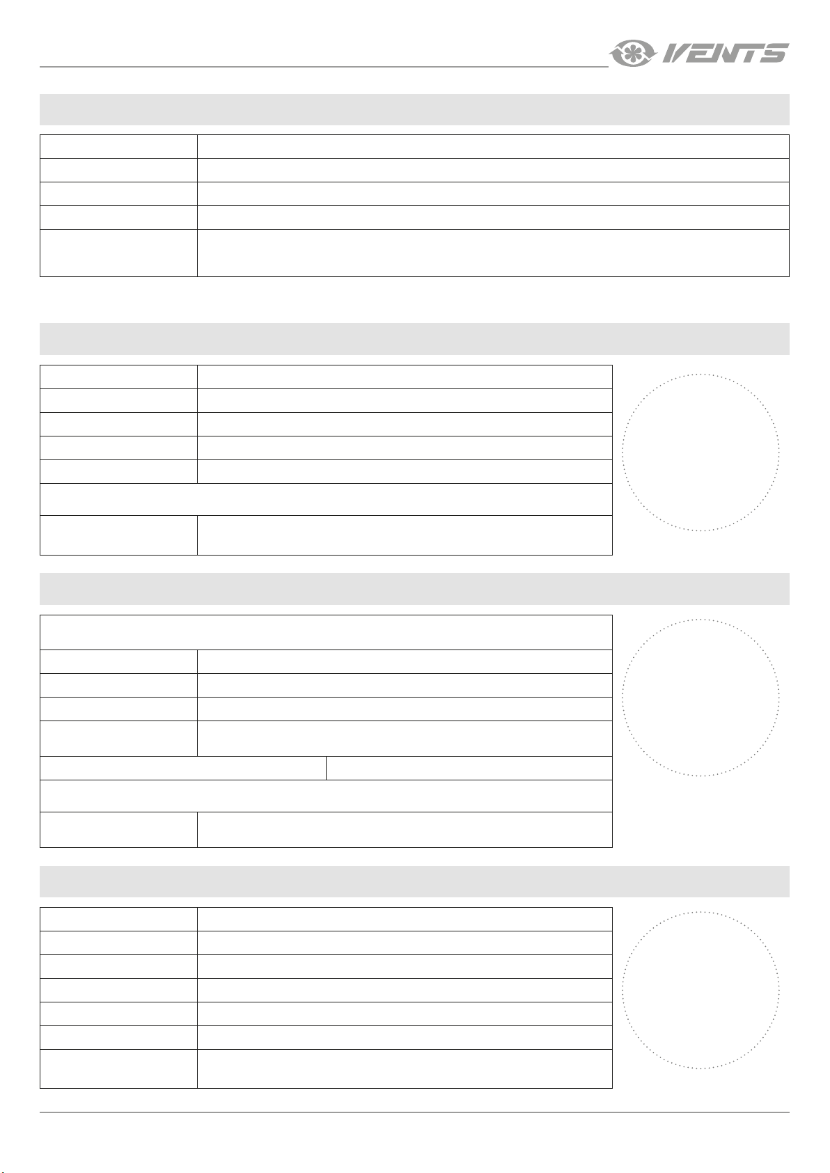
CERTIFICATE OF ACCEPTANCE
Unit Type Heat and energy recovery air handling unit
Model VUT/VUE _______________________
Serial Number
Manufacture Date
Quality Inspector’s
Stamp
SELLER INFORMATION
Seller
Address
Phone Number
E-mail
Purchase Date
This is to certify acceptance of the complete unit delivery with the user’s manual. The warranty terms are
acknowledged and accepted.
Customer’s Signature
INSTALLATION CERTIFICATE
The VUT/VUE _______________________ unit has been connected to power mains pursuant to the
requirements stated in the present user’s manual.
Seller
Address
Phone Number
Installation
Technician’s Full Name
Installation Date: Signature:
The unit has been installed in accordance with the provisions of all the applicable local and national construction,
electrical and technical codes and standards. The unit operates normally as intended by the manufacturer.
Signature:
Seller’s Stamp
Installation Stamp
WARRANTY CARD
Unit Type Heat and energy recovery air handling unit
Model VUT/VUE _______________________
Serial Number
Manufacture Date
Purchase Date
Warranty Period
Seller
www.ventilation-system.com
Seller’s Stamp
19
Page 20

V203EN-01
 Loading...