

Page 1

Operator’s Manual
& Parts Drawings
LB540
Power Broom
Original Operator’s Manual
VENTRAC.COM
Revised 12/07/18
09.10032 Rev. 06
Page 2

View all manuals
Visit ventrac.com/manuals
500 Venture Drive
Orrville Oh 44667
www.ventrac.com
for the latest version of this
operator’s manual.
A downloadable parts manual
is also available.
To the Owner
Contact Information and Product Identication
If you need to contact an authorized Ventrac dealer for information on servicing your product,
always provide the product model and serial numbers.
Please ll in the following information for future reference. See the picture(s) below to nd the
location of the identication numbers. Record them in the spaces provided.
Date of Purchase: __________________________________________________________________
Dealer: ___________________________________________________________________________
Dealer Address: ____________________________________________________________________
____________________________________________________________________
Dealer Phone Number: ______________________________________________________________
Dealer Fax Number: ________________________________________________________________
Model # (A): ___________________________
Serial # (B): ____________________________
Afx Part/Serial Number label here.
A
B
Venture Products Inc. reserves the right to make changes
in design or specications without obligation to make like
changes on previously manufactured products.
2
Page 3

TABLE OF CONTENTS
INTRODUCTION PAGE 5
Product Description ................................................................................................................................ 5
Why Do I Need an Operator’s Manual? ................................................................................................. 5
Using Your Manual ................................................................................................................................. 6
Manual Glossary ....................................................................................................................................6
SAFETY PAGE 7
Safety Decals ......................................................................................................................................... 7
General Safety Procedures .................................................................................................................... 8
Training Required ...................................................................................................................................8
Personal Protective Equipment Requirements ......................................................................................8
Operation Safety ....................................................................................................................................8
Preventing Accidents ..............................................................................................................................9
Keep Riders O ...................................................................................................................................... 9
Operating On Slopes ............................................................................................................................10
Roadway Safety ................................................................................................................................... 10
Truck Or Trailer Transport ....................................................................................................................10
Maintenance ......................................................................................................................................... 11
Fuel Safety ........................................................................................................................................... 11
Hydraulic Safety ................................................................................................................................... 12
OPERATIONAL CONTROLS PAGE 14
Operational Control Locations ..............................................................................................................14
GENERAL OPERATION PAGE 15
Daily Inspection .................................................................................................................................... 15
Attaching ..............................................................................................................................................15
Detaching ............................................................................................................................................. 15
Operating Procedure ............................................................................................................................ 16
Gauge Wheel Height Adjustment ......................................................................................................... 16
SERVICE PAGE 17
Cleaning and General Maintenance.....................................................................................................17
Belt Inspection ...................................................................................................................................... 17
Belt Replacement ................................................................................................................................. 17
Lubrication Locations ...........................................................................................................................17
Maintenance Schedule .........................................................................................................................18
Storage ................................................................................................................................................. 18
Maintenance Checklist ......................................................................................................................... 19
SPECIFICATIONS PAGE 20
Dimensions ..........................................................................................................................................20
Features ............................................................................................................................................... 20
3
Page 4

TABLE OF CONTENTS
PARTS PAGE 22
Main Frame & Hitch .............................................................................................................................22
Brush Assembly & Drive Chain ............................................................................................................24
Belt Drive, Gearbox, & Hydraulics ........................................................................................................26
Shields & Belt Retainer ........................................................................................................................28
39.35403 Outside Gauge Wheel Kit .....................................................................................................30
70.8029 Front Belting Curtain Kit ......................................................................................................... 32
WARRANTY PAGE 34
4
Page 5
INTRODUCTIONINTRODUCTION
enture Products Inc. is pleased to provide you with your new
V
Ventrac power broom! We hope that Ventrac equipment will
provide you with a ONE Tractor Solution.
Listed below are just some of the items that can provide you
versatility as you use your LB540 power broom. Please visit
our website, or contact your authorized Ventrac dealer for a
complete list of items available for your new power broom.
Accessories
Item Description
Outside Gauge Wheel Kit 39.35403
Front Belting Curtain Kit 70.8029
Part Number
Product Description
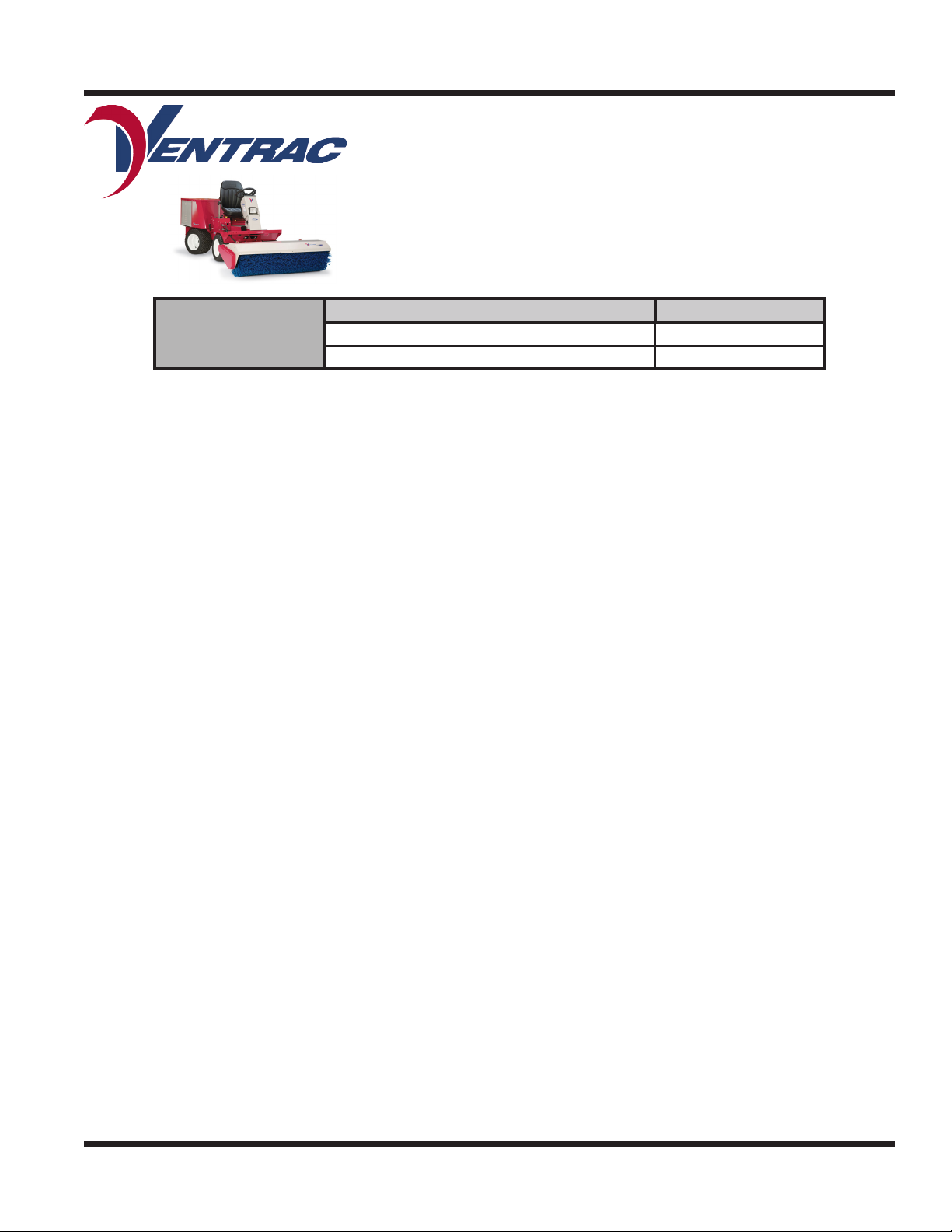
The Ventrac LB540 power broom is designed for the sweeping and removal of snow, leaves, dirt, light
gravel, and other materials from parking lots, sidewalks, and other surfaces. Heavy duty nylon bristles
make short work of any clean up job without damaging the surface below.
A hydraulic cylinder angles the broom left or right from the operator’s seat. The corner-less frame on the left
side permits angular sweeping from curbs and corners.
Adjustable gauge wheels set the height of work for precise adjustment and hold the broom in an upright
position when detached, to allow for quick and easy reattachment.
Optional outrigger wheels allow for controlled adjustment when de-thatching turf.
An optional front debris curtain is available for less over throw of material.
Why Do I Need an Operator’s Manual?
This manual has been created to help you gain the important knowledge of what is needed to safely
operate, maintain, and service your machine. It is divided into sections for convenient reference of the
appropriate section.
You must read and understand the operator’s manual for each piece of Ventrac equipment you own. Reading the operator’s manual will help you become familiar with each specic piece of equipment. Understanding the operator’s manual will help you, as well as others, avoid personal injury and/or damage to the
equipment. Keep this manual with the machine at all times. The manual should remain with the machine
even if it is sold. If this manual becomes damaged or unreadable, it should be replaced immediately. Contact your local Ventrac dealer for a replacement.
When using a Ventrac attachment, be sure to read and follow the safety and operating instructions of both
the power unit and the attachment being used to ensure the safest operation possible.
The information in this manual provides the operator with the safest procedures to operate the machine
while getting the maximum use out of the unit. Failure to follow the safety precautions listed in this manual
may result in personal injury and/or damage to the equipment.
Introduction - 5
Page 6
INTRODUCTION
Using Your Manual
Throughout this manual, you will encounter special messages and symbols that identify potential safety
concerns to help you as well as others avoid personal injury or damage to the equipment.
SYMBOL DEFINITIONS
ATTENTION
This symbol identies potential health and
safety hazards. It marks safety precautions.
Your safety and the safety of others is involved.
There are three signal words that describe the level of safety concern: Danger, Warning, and Caution.
Safety should always be the #1 priority when working on or operating equipment. Accidents are more likely
to occur when proper operating procedures are not followed or inexperienced operators are involved.
Note: Right-Hand and Left-Hand orientations may be referred to at dierent places throughout this manual.
Right-Hand and Left-Hand is determined as if sitting on the power unit seat facing forward.
SIGNAL WORD DEFINITIONS
Indicates an imminently hazardous situation
which, if not avoided, will result in death or
serious injury. This signal word is limited to the
most extreme cases.
Indicates a potentially hazardous situation
which, if not avoided, could result in death or
serious injury.
Indicates a potentially hazardous situation
which, if not avoided, may result in minor or
moderate injury and/or property damage. It may
also be used to alert against unsafe practices.
Manual Glossary
Power Unit A Ventrac tractor or other Ventrac engine powered device that may be operated by itself or
with an attachment or accessory.
Attachment A piece of Ventrac equipment that requires a Power Unit for operation.
Accessory A device that attaches to a Power Unit or Attachment to extend its capabilities.
Machine Describes any “Attachment” or “Accessory” that is used in conjunction with a power unit.
Introduction - 6
Page 7
SAFETY
SAFETY
Safety Decals
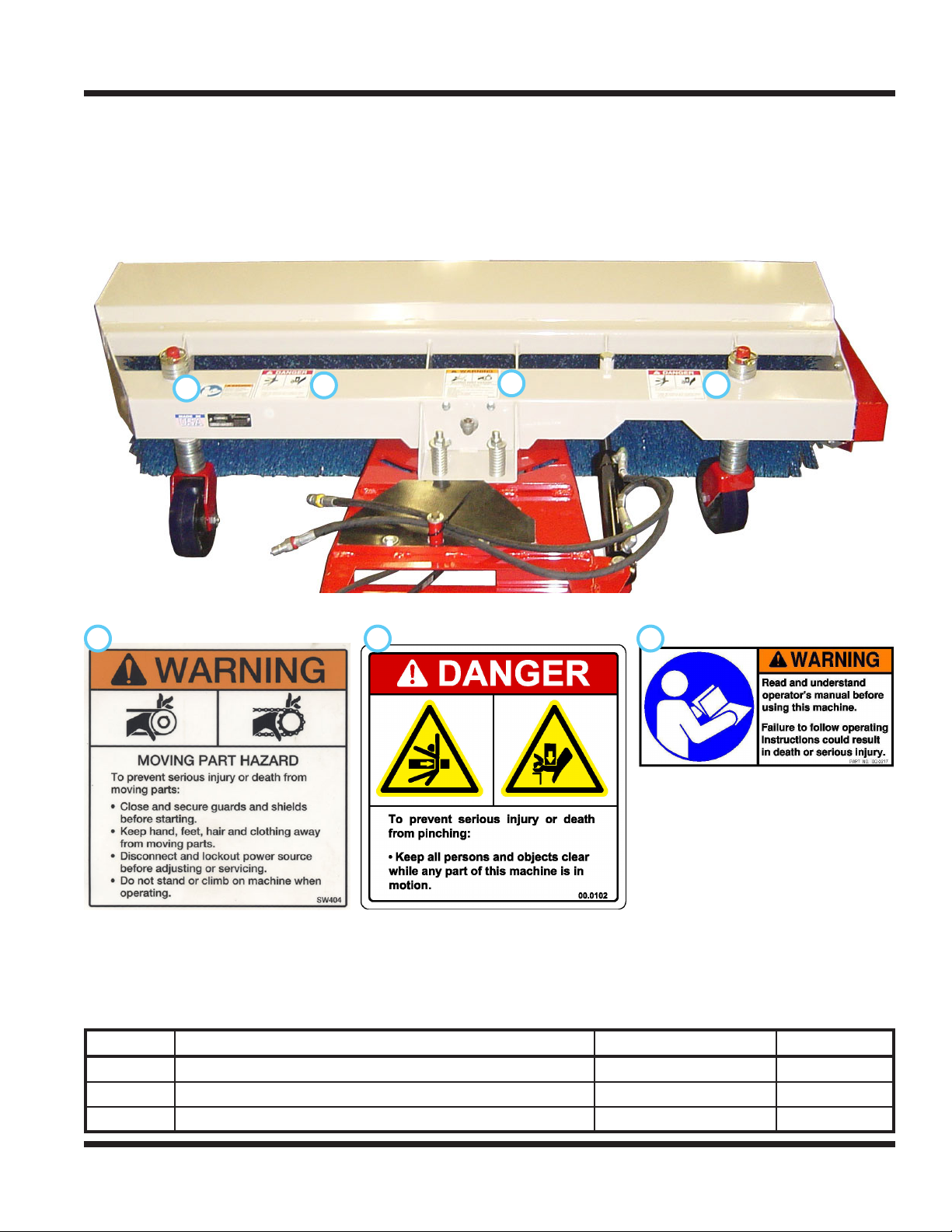
The following safety decals must be maintained on your LB540 power broom.
Keep all safety decals legible. Remove all grease, dirt, and debris from safety decals and instructional
labels. If any decals are faded, illegible, or missing, contact your dealer promptly for replacements.
When new components are installed, be sure that current safety decals are axed to the replacement
components.
C
A
B
B C
A
B
Decal Description Part Number Quantity
A Warning, Moving Part Hazard 00.0101 1
B Danger, Pinching Hazard 00.0102 2
C Warning, Read Owner’s Manual 00.0217 1
Safety - 7
Page 8
SAFETY
General Safety Procedures
for Ventrac Power Units, Attachments, & Accessories
Training Required
• The owner of this machine is solely responsible for properly training the operators.
• The owner/operator is solely responsible for the operation of this
machine and prevention of accidents or injuries occurring to him/herself, other people, or property.
• Do not allow operation or service by children or untrained personnel.
Local regulations may restrict the age of the operator.
• Before operating this machine, read the operator’s manual and understand its contents.
• If the operator of the machine cannot understand this manual, then it
is the responsibility of this machine’s owner to fully explain the material
within this manual to the operator.
• Learn and understand the use of all controls.
• Know how to stop the power unit and all attachments quickly in the event of an emergency.
Personal Protective Equipment Requirements
It is the responsibility of the owner to be sure that the operators use the proper personal protective equipment while operating the machine. Required personal protective equipment includes, but is not limited to,
the following list.
• Wear a certied ear protection device to prevent loss of hearing.
• Prevent eye injury by wearing safety glasses while operating the machine.
• Closed toe shoes must be worn at all times.
• Long pants must be worn at all times.
• When operating in dusty conditions, it is recommended that a dust mask be worn.
Operation Safety
• Inspect machine before operation. Repair or replace any damaged, worn, or missing parts. Be sure
guards and shields are in proper working condition and are secured in place. Make all necessary
adjustments before operating machine.
• Some pictures in this manual may show shields or covers opened or removed in order to clearly illustrate
any instructions. Under no circumstance should the machine be operated without these devices in place.
• Alterations or modications to this machine can reduce safety and could cause damage to the machine.
Do not alter safety devices or operate with shields or covers removed.
• Before each use, verify that all controls function properly and inspect all safety devices. Do not operate
if controls or safety devices are not in proper working condition.
• Check parking brake function before operating. Repair or adjust parking brake if necessary.
• Observe and follow all safety decals.
• All controls are to be operated from the operator’s station only.
• Always wear a seat belt if the machine has a roll cage/bar installed and in upright position.
• Ensure the attachment or accessory is locked or fastened securely to the power unit before operating.
• Ensure that all bystanders are clear of the power unit and attachment before operating. Stop machine if
someone enters your work area.
• Always be alert to what is happening around you, but do not lose focus on the task you are performing.
Always look in the direction the machine is moving.
• Look behind and down before backing up to be sure of a clear path.
• If you hit an object, stop and inspect the machine. Make all necessary repairs before operating machine again.
• Stop operation immediately at any sign of equipment failure. An unusual noise can be a warning of equipment
failure or a sign that maintenance is required. Make all necessary repairs before operating machine again.
Safety - 8
Page 9
SAFETY
General Safety Procedures
for Ventrac Power Units, Attachments, & Accessories
Operation Safety (continued)
• If equipped with a high/low range feature, never shift between high and low range while on a slope.
Always move the machine to level ground and engage the parking brake before shifting range.
• Do not leave machine unattended while it is running.
• Always park the machine on level ground.
• Always shut o engine when connecting attachment drive belt to the power unit.
• Never leave the operator’s station without lowering the attachment to the ground, setting the parking
brake, shutting o the engine, and removing the ignition key. Make sure all moving parts have come to
a complete stop before dismounting.
• Never leave equipment unattended without lowering the attachment to the ground, setting the parking
brake, shutting o the engine, and removing the ignition key.
• Only operate in well-lit conditions.
• Do not operate when there is a risk of lightning.
• Never direct the discharge of any attachment in the direction of people, buildings, animals, vehicles, or
other objects of value.
• Never discharge material against a wall or obstruction. Material may ricochet back towards the operator.
• Use extra caution when approaching blind corners, shrubs, trees, or other objects that may obscure vision.
• Do not run the engine in a building without adequate ventilation.
• Do not touch the engine or the muer while the engine is running or immediately after stopping the engine.
These areas may be hot enough to cause a burn.
• Do not change the engine governor settings or over-speed the engine. Operating engine at excessive speed
may increase the hazard of personal injury.
• To reduce the hazard of re, keep the battery compartment, engine, and muer areas free of grass, leaves,
excessive grease, and other ammable materials.
Preventing Accidents
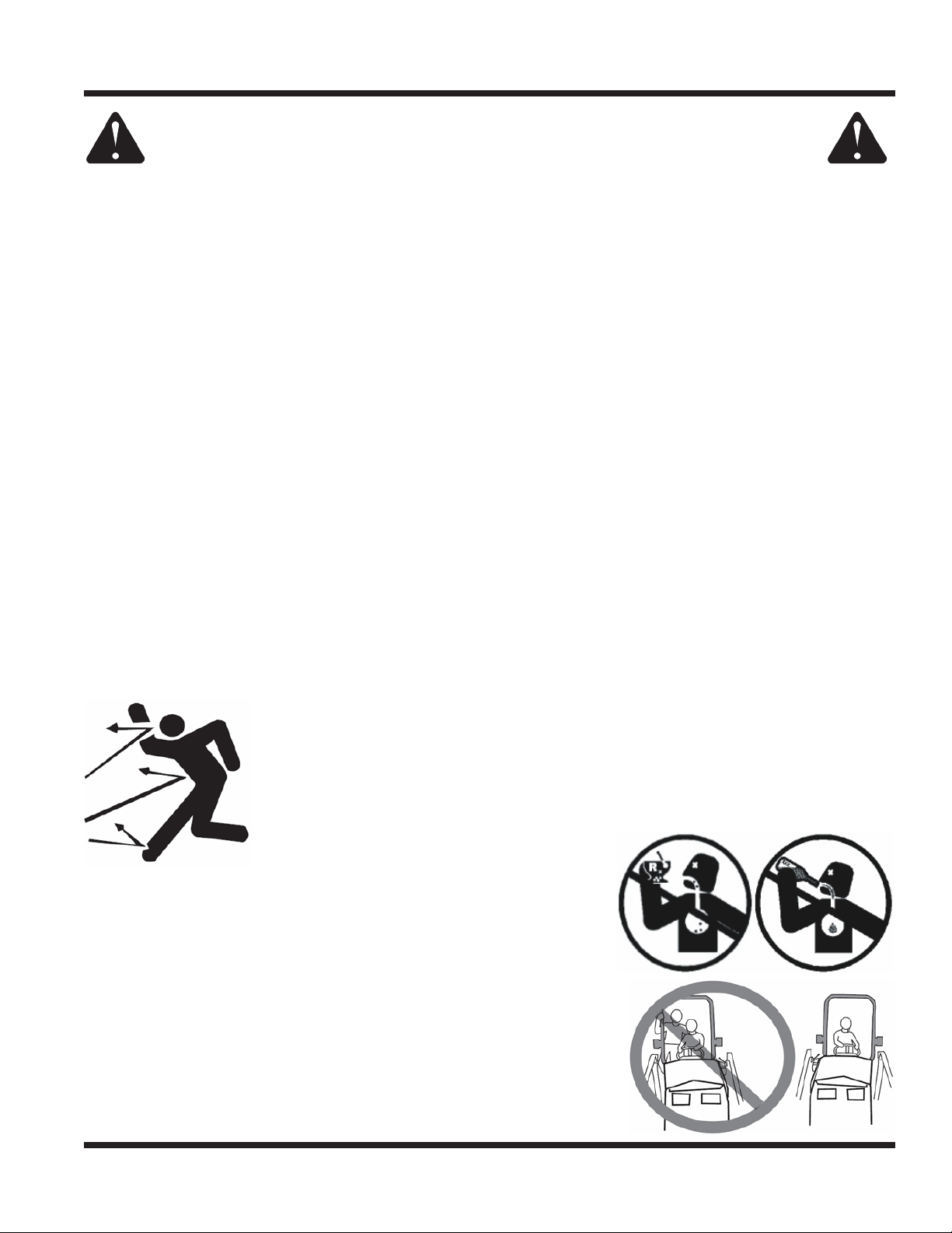
• Clear working area of objects that might be hit or thrown from machine.
• Keep people and pets out of working area.
• Know the work area well before operation. Do not operate where traction or
stability is questionable.
• Reduce speed when you are operating over rough ground.
• Equipment can cause serious injury and/or death when improperly used.
Before operating, know and understand
the operation and safety of the power
unit and the attachment being used.
• Do not operate machine if you are not in good physical and
mental health, if you will be distracted by personal devices, or are
under the inuence of any substance which might impair decision, dexterity, or judgment.
• Children are attracted to machine activity. Be aware of children
and do not allow them in the working area. Turn o the machine if
a child enters the work area.
Keep Riders O
• Only allow the operator on the power unit. Keep riders o.
• Never allow riders on any attachment or accessory.
Safety - 9
Page 10
SAFETY
General Safety Procedures
for Ventrac Power Units, Attachments, & Accessories
Operating On Slopes
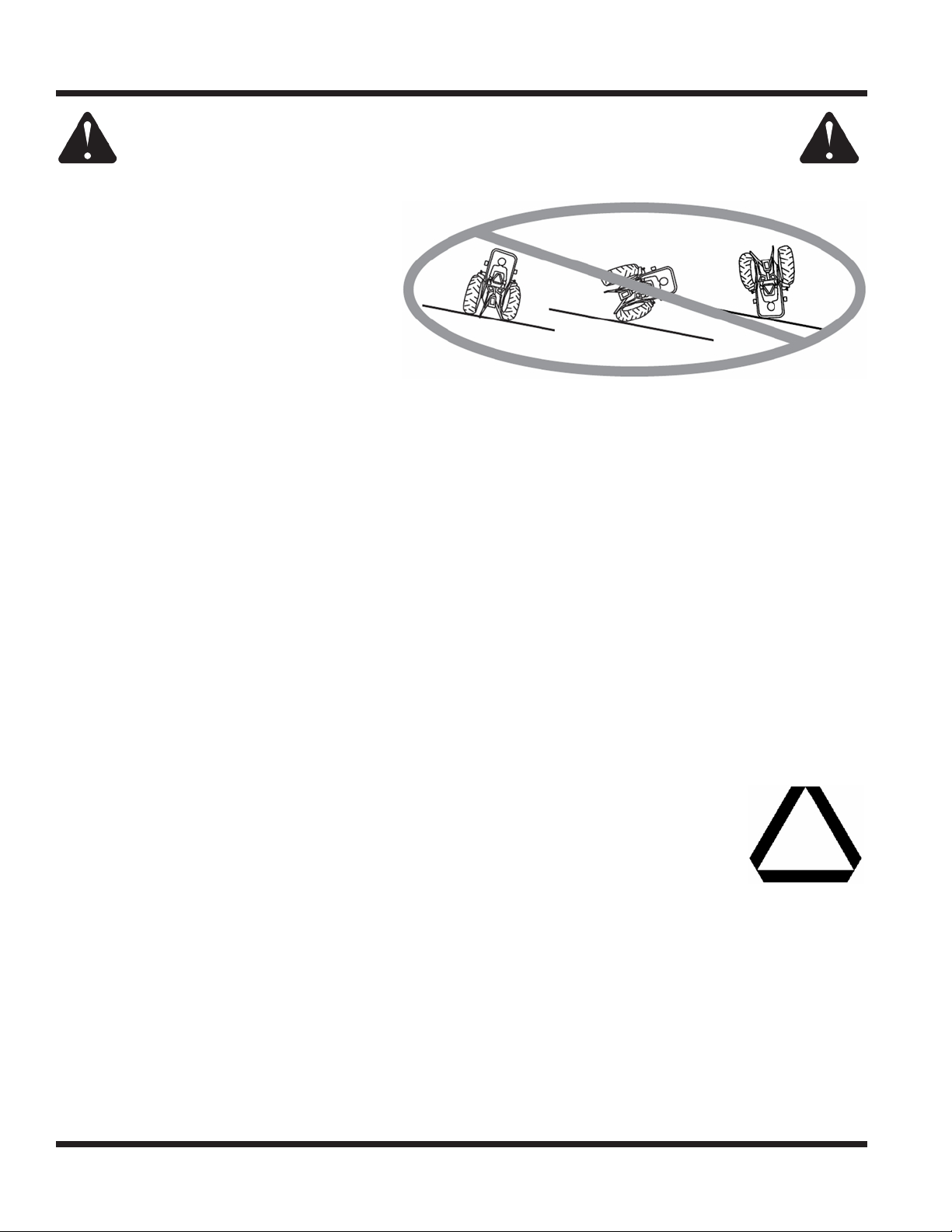
• Slopes can cause loss-of-control and
tip-over accidents, which can result in
severe injury or death. Be familiar with the
emergency parking brake, along with the
power unit controls and their functions.
• If power unit is equipped with a fold down
roll bar, it must be locked in the upright
position when operating on any slope.
• Use low range (if equipped) when operating
on slopes greater than 15 degrees.
• Do not stop or start suddenly when operating on slopes.
• Never shift between high and low range while on a slope. Always move the power unit to level ground
and engage the parking brake before shifting range or placing the power unit in neutral.
• Variables such as wet surface and loose ground will reduce the degree of safety. Do not drive where
machine could lose traction or tip over.
• Keep alert for hidden hazards in the terrain.
• Stay away from drop-os, ditches, and embankments.
• Sharp turns should be avoided when operating on slopes.
• Pulling loads on hills decreases safety. It is the responsibility of the owner/operator to determine loads
that can safely be controlled on slopes.
• Transport machine with attachment lowered or close to the ground to improve stability.
• While operating on slopes, drive in an up and down direction when possible. If turning is necessary
while driving across slopes, reduce speed and turn slowly in the downhill direction.
• Assure a sucient supply of fuel for continuous operation. A minimum of one-half tank of fuel is recommended.
Roadway Safety
• Operate with safety lights when operating on or near roadways.
• Obey all state and local laws concerning operation on roadways.
• Slow down and be careful of trac when operating near or crossing roadways. Stop before crossing
roads or sidewalks. Use care when approaching areas or objects that may obscure vision.
• If there is doubt of safety conditions, discontinue machine operation until a time when
operation can be performed safely.
• When operating near or on roadways, have a Slow Moving Vehicle Emblem clearly
displayed.
Truck Or Trailer Transport
• Use care when loading or unloading machine into a truck or trailer.
• Use full width ramps for loading machine into a truck or trailer.
• The parking brake is not sucient to lock the machine during transport. Always secure the power unit
and/or attachment to the transporting vehicle securely using straps, chains, cable, or ropes. Both front
and rear straps should be directed down and outward from the machine.
• Shut o fuel supply to power unit during transport on truck or trailer.
• If equipped, turn the battery disconnect switch to the O position to shut o electrical power.
Safety - 10
Page 11
SAFETY
General Safety Procedures
for Ventrac Power Units, Attachments, & Accessories
Maintenance
• Keep all safety decals legible. Remove all grease dirt, and debris from safety decals and instructional labels.
• If any decals are faded, illegible, or missing, contact your dealer promptly for replacements.
• When new components are installed, be sure that current safety decals are axed to the replacement
components.
• If any component requires replacement, use only original Ventrac replacement parts.
• Always turn the battery disconnect to the O position or disconnect the battery before performing any
repairs. Disconnect the negative terminal rst and the positive terminal last. Reconnect the positive
terminal rst and the negative terminal last.
• Keep all bolts, nuts, screws, and other fasteners properly tightened.
• Always lower the attachment to the ground, engage parking brake, shut o engine, and remove the
ignition key. Make sure all moving parts have come to a complete stop before cleaning, inspection,
adjusting or repairing.
• If the power unit, attachment, or accessory requires repairs or adjustments not instructed in the operator’s
manual, the power unit, attachment, or accessory must be taken to an authorized Ventrac dealer for service.
• Never perform maintenance on the power unit and/or attachment if someone is in the operator’s station.
• Always use protective glasses when handling the battery.
• Check all fuel lines for tightness and wear on a regular basis. Tighten or repair them as needed.
• To reduce the hazard of re, keep the battery compartment, engine, and muer areas free of grass,
leaves, and excessive grease.
• Do not touch the engine, the muer, or other exhaust components while the engine is running or imme-
diately after stopping the engine. These areas may be hot enough to cause a burn.
• Allow the engine to cool before storing and do not store near an open ame.
• Do not change the engine governor settings or over-speed the engine. Operating engine at excessive
speed may increase the hazard of personal injury.
• Springs may contain stored energy. Use caution when disengaging or removing springs and/or spring
loaded components.
• An obstruction or blockage in a drive system or moving/rotating parts may cause a buildup of stored
energy. When the obstruction or blockage is removed, the drive system or moving/rotating parts may
move suddenly. Do not attempt to remove an obstruction or blockage with your hands. Keep hands,
feet, and clothing away from all power-driven parts.
• Dispose of all uids in accordance with local laws.
Fuel Safety
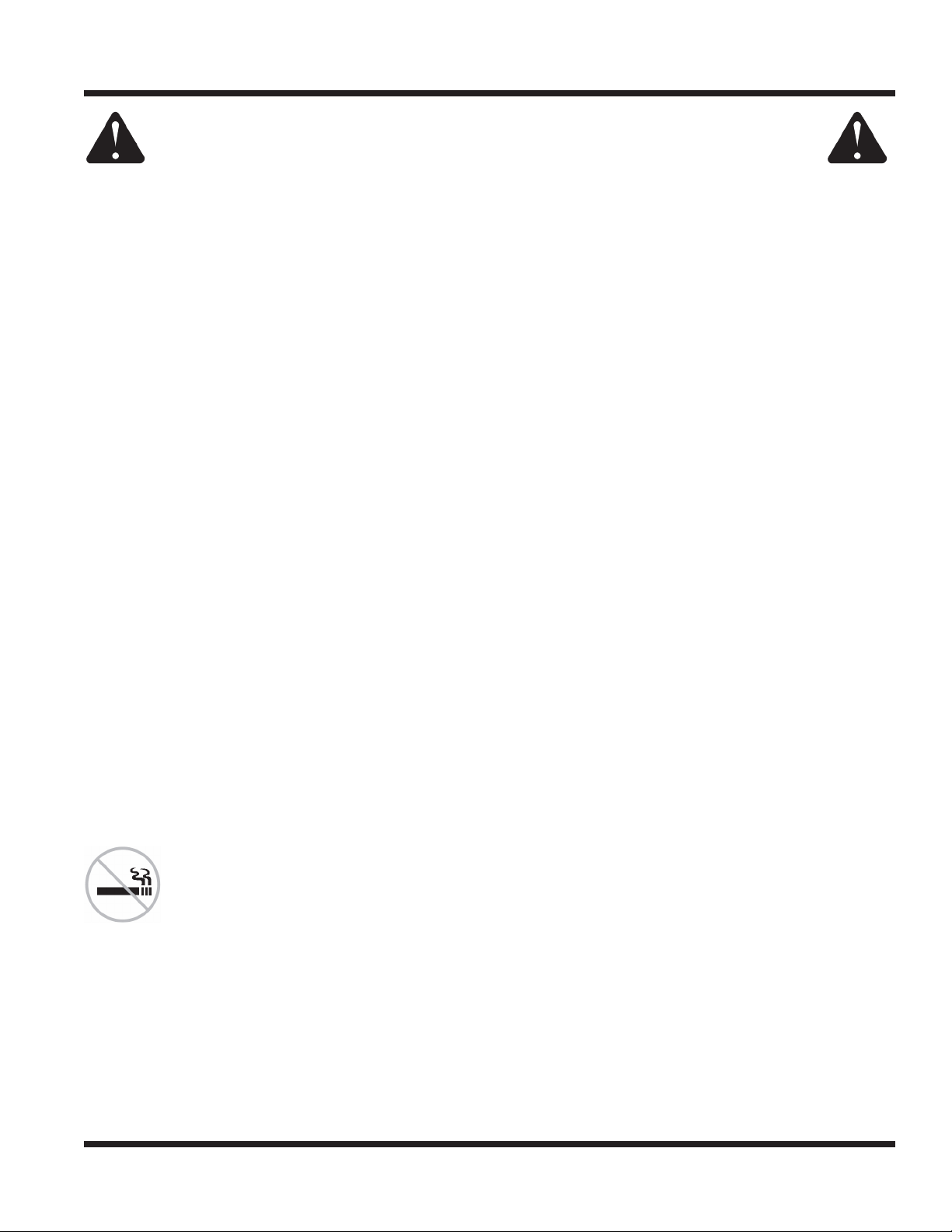
• To avoid personal injury or property damage, use extreme care in handling gasoline. Gaso-
line is extremely ammable and the vapors are explosive.
• Do not refuel machine while smoking or at a location near ames or sparks.
• Always refuel the machine outdoors.
• Do not store machine or fuel container indoors where fumes or fuel can reach an open
ame, spark, or pilot light.
• Only store fuel in an approved container. Keep out of reach of children.
• Never ll containers inside a vehicle or on a truck or trailer bed with a plastic liner. Always place containers
on the ground away from your vehicle before lling.
• Remove machine from the truck or trailer and refuel it on the ground. If this is not possible, refuel the
machine using a portable container, rather than from a fuel dispenser nozzle.
• Never remove fuel cap or add fuel with the engine running. Allow engine to cool before refueling.
• Never remove fuel cap while on a slope. Only remove when parked on a level surface.
• Replace all fuel tank and container caps securely.
Safety - 11
Page 12
SAFETY
General Safety Procedures
for Ventrac Power Units, Attachments, & Accessories
Fuel Safety (continued)
• Do not overll fuel tank. Only ll to bottom of fuel neck, do not ll fuel neck full. Overlling of fuel tank could
result in engine ooding, fuel leakage from the tank, and/or damage to the emissions control system.
• If fuel is spilled, do not attempt to start the engine. Move the power unit away from the fuel spill and
avoid creating any source of ignition until fuel vapors have dissipated.
• If the fuel tank must be drained, it should be drained outdoors into an approved container.
• Dispose of all uids in accordance with local laws.
• Check all fuel lines for tightness and wear on a regular basis. Tighten or repair them as needed.
• The fuel system is equipped with a shut-o valve. Shut o the fuel when transporting the machine to
and from the job, when parking the machine indoors, or when servicing the fuel system.
Hydraulic Safety
• Make sure all hydraulic connections are tight and all hydraulic hoses and tubes are in good condition.
Repair any leaks and replace any damaged or deteriorated hoses or tubes before starting the machine.
• Hydraulic leaks can occur under high pressure. Hydraulic leaks require special care and attention.
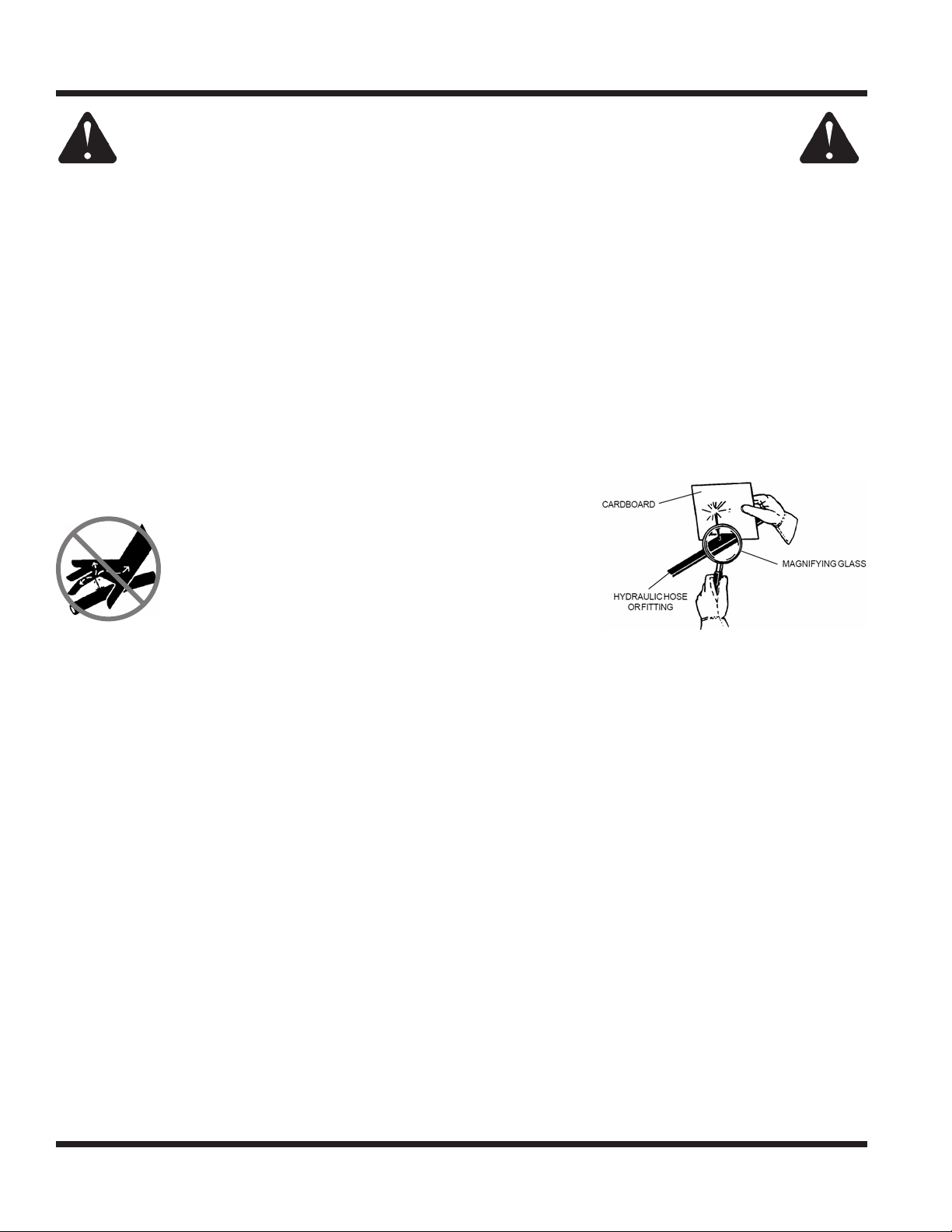
• Use a piece of cardboard and a magnifying glass to locate suspected hydraulic leaks.
• Keep body and hands away from pinhole leaks
or nozzles that eject high pressure hydraulic uid.
Hydraulic uid escaping under high pressure can
penetrate the skin causing serious injury, leading to
severe complications and/or secondary infections
if left untreated. If hydraulic uid is injected into the
skin, seek immediate medical attention no matter
how minor the injury appears.
• Hydraulic system may contain stored energy. Before performing maintenance or repairs on the hydraulic
system, remove attachments, engage parking brake, disengage weight transfer system (if equipped),
shut o engine, and remove ignition key. To relieve pressure on the auxiliary hydraulic system, shut o the
power unit engine and move the hydraulic control lever left and right before disconnecting the auxiliary
hydraulic quick couplers.
• Dispose of all uids in accordance with local laws.
Safety - 12
Page 13

SAFETY
LB540 Safety Procedures
• The LB540 power broom is designed to sweep. Do not use it to push or pull objects.
• The broom can create a dust cloud that may obstruct your vision. Generally, slowing the rotational
speed of the broom by reducing power unit engine RPM will reduce the amount of dust created.
• Use caution when sweeping near anything that could be damaged by thrown objects. Whenever possible,
sweep materials away from buildings and other objects of value. When sweeping near buildings or objects
of value, slowing the rotational speed of the broom by reducing power unit engine RPM will reduce the
distance and velocity at which objects can be thrown from the broom.
• Attachment hydraulic system may contain stored energy. Before performing maintenance or repairs on
the hydraulic system, the attachment’s auxiliary hydraulic hoses must be disconnected from the power
unit. Lower the attachment to the ground, shut o power unit engine, move the secondary S.D.L.A. lever
left and right to relieve auxiliary hydraulic pressure, and disconnect the auxiliary hydraulic quick couplers.
Safety - 13
Page 14
OPERATIONAL CONTROLS
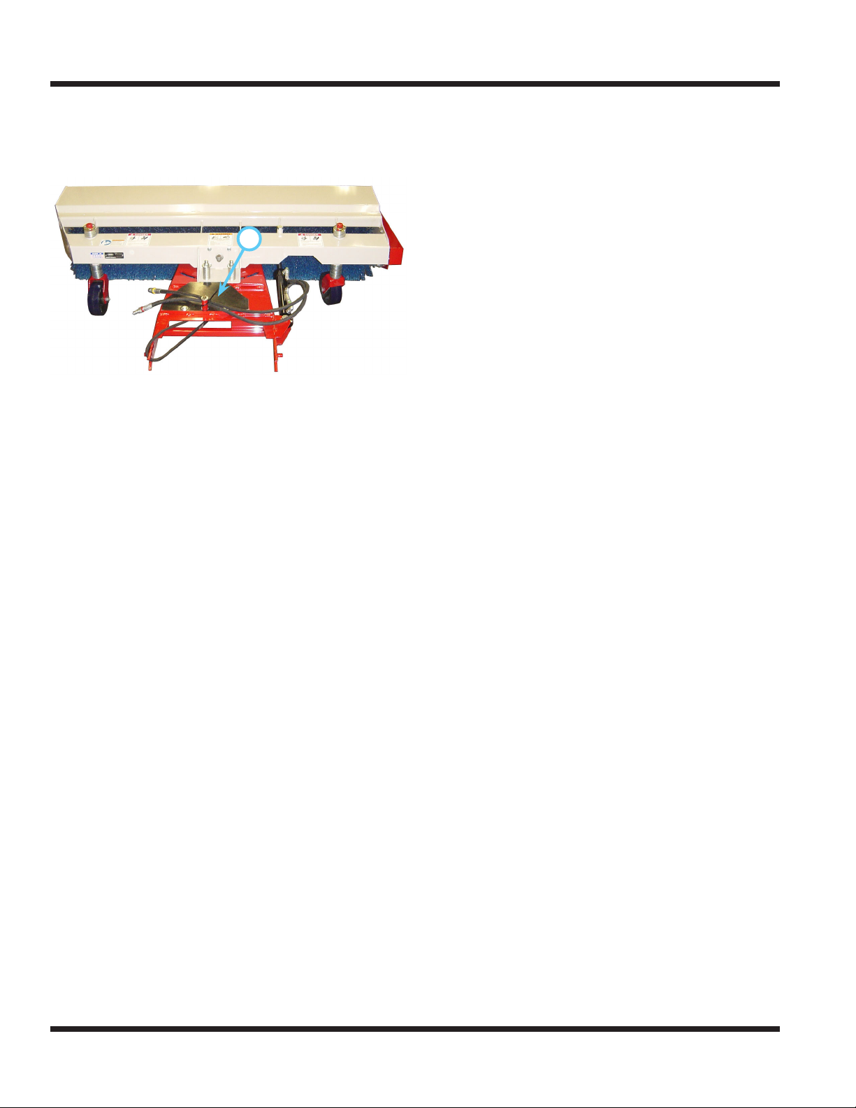
Operational Control Locations
Use the following images to help identify the locations
of operational controls. The letter next to each control
can be referenced to the list that follows these images.
A
A - Belt Tension Spring (underneath belting)
Rotate the belt tension spring to the right and secure
with the clevis pin to apply tension to the attachment
drive belt. Remove the clevis pin to release the belt
tension spring and remove tension from the attachment drive belt, allowing the operator tor remove or
install the attachment drive belt onto the power unit.
Operation - 14
Page 15
GENERAL OPERATION
Daily Inspection
Always set the parking brake, shut o power
unit engine, remove the ignition key, and ensure
all moving parts have come to a complete stop
before inspecting components, or attempting
any repair or adjustment.
1.
Park machine on a level surface, with the engine
shut o and all uids cold.
2. Perform a visual inspection of both the power
unit and the power broom. Look for loose or
missing hardware, damaged components, or
signs of wear.
3. Inspect hydraulic hoses, hydraulic ttings, and
fuel lines to ensure tight, leak free connections.
4. Inspect the drive belt. The belt should be in good
condition. Service as required.
5. Check the gauge wheel height setting and adjust
if necessary.
6. Refer to the power unit operator’s manual.
Check the power unit’s engine oil, hydraulic oil,
cooling system, tire pressure, and fuel level. Add
uid or service as required.
7. Test the power unit’s operator safety interlock
system*.
Attaching
1. Drive the power unit slowly forward into the hitch
arms of the power broom. Align the lift arms of
the power unit with the power broom hitch arms
by raising or lowering the front hitch and complete the engagement.
2. Once completely engaged, close the front hitch
locking lever.*
3. Engage the parking brake* and shut o the
engine.
4. Place the attachment belt onto the PTO drive
pulley on the power unit. Ensure the belt is properly seated in each pulley.
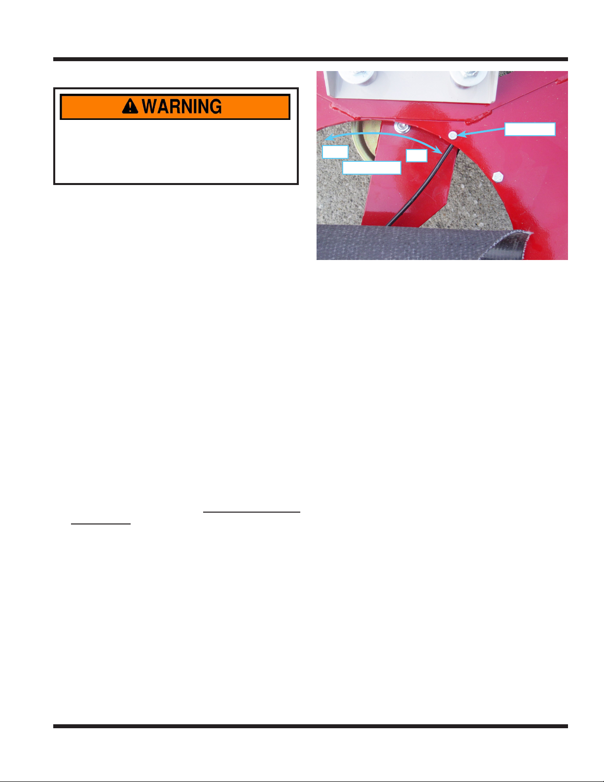
Clevis Pin
OFF
Belt Tension
5.
Lift the belt tension spring cover, remove the
clevis pin, and rotate the spring to the right past
the clevis pin hole. Reinsert the clevis pin and
secure with the hairpin.
6. Wipe hose ends clean, and connect to the
power unit’s hydraulic quick couplers. If
equipped, connect the hoses and quick couplers
so the red indicators are paired together and the
yellow indicators are paired together.
ON
Detaching
1. Park the power unit on a level surface and set
the parking brake.*
2. Lower the power broom to the ground.
3. Shut o power unit engine.
4. Lift the belt tension spring cover and remove the
clevis pin to release the spring tension. Reinstall
the clevis pin and secure with the hairpin.
5. Remove the attachment belt from the PTO drive
pulley of the power unit.
6. Disconnect the hydraulic quick couplers from the
power unit and store the hose ends in the two
holes in the top of the chain drive cover.
7. Disengage the front hitch locking lever.*
8. Restart power unit and slowly back away from
the power broom. A side to side movement of
the steering wheel may aid in disengagement.
* Refer to power unit operator’s manual for operation of
power unit controls.
Operation - 15
Page 16
GENERAL OPERATION
Operating Procedure
Before operation, perform daily inspection and
engage the power unit’s weight transfer.
Move the machine into position and lower the power
broom to the ground. Place the power unit’s primary
SDLA lever in the oat position by pushing it to the
right until the detent engages. The lever will stay
in this position until intentionally removed. Use the
power unit’s secondary SDLA lever to adjust the
broom to the desired angle.
WARNING
When the broom is angled to the left or right,
pinch points are created. Make sure there are
no people or objects present between the broom
frame and the power unit.
With the power unit’s engine running between 2,000
and 2,500 RPM, engage the PTO switch. Adjust
the power unit throttle to achieve the desired broom
rotational speed. Drive forward at a speed that is
safe and gives the desired results.
The power broom can be used to sweep debris,
including leaves and snow, from driveways, sidewalks, parking lots, etc. The power broom can
eectively sweep several inches of snow. The type
of snow and prevailing winds will aect the results.
When sweeping, cooperate with the wind direction
as much as possible. Slowing the broom rotation
RPM can reduce blowing dust. Reduce rotation
speed by slowing the power unit engine RPM.
Excessive amounts of debris on the broom frame
will obstruct vision and add unwanted weight. Clean
as necessary.
Gauge Wheel Height Adjustment
The power broom is equipped with two adjustable
gauge wheels. As the nylon bristles of the broom
rotor wear down, the gauge wheels will need to be
adjusted to maintain proper ground contact. The
vertical adjustment of the gauge wheels is done by
the placement of a series of washers above and
below the mounting tube. The number of upper and
lower washers must be the same on both the left
and right gauge wheels.
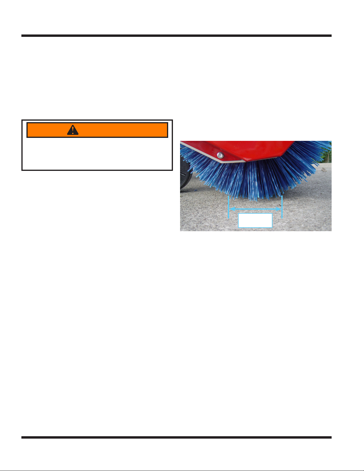
The suggested setting for the gauge wheels is the
point at which the broom sweeps 2 to 4 inches (5 to
10 cm) of surface area when the machine is parked.
2 - 4 inches
5 - 10 cm
Some situations may require a more or less aggressive sweeping action. Gauge wheel adjustment,
broom speed, and travel speeds are factors to apply.
Operation - 16
Page 17
SERVICE
SERVICE
Always set the parking brake, shut o power
unit engine, remove the ignition key, and ensure
all moving parts have come to a complete stop
before inspecting components or attempting any
repair or adjustment.
Attention
If any component requires replacement, use only
original Ventrac replacement parts.
Cleaning and General Maintenance
For best results, and to maintain the nish of the
LB540 power broom, clean or wash the power broom
to remove dirt, gravel, and debris.
Belt Inspection
Inspecting the drive belt of the power broom can
prevent sudden belt failure by nding problems
before they cause a belt to break.
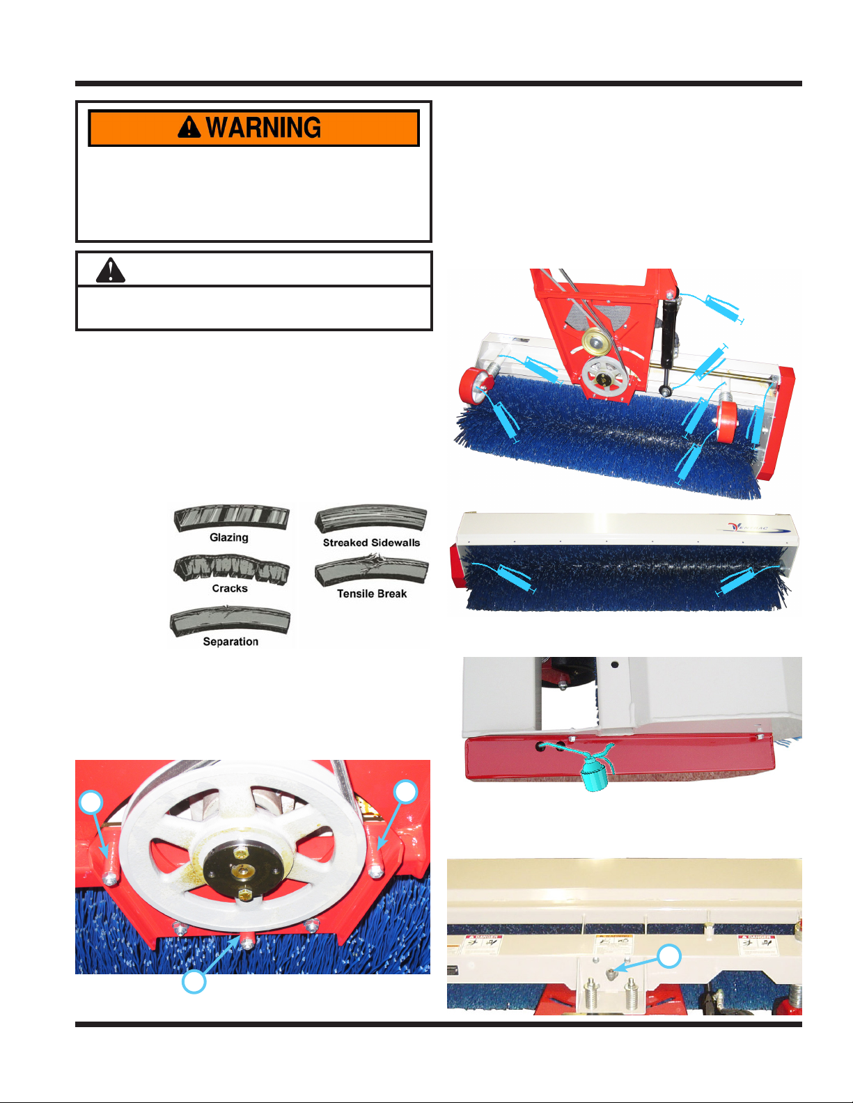
Typical wear
on a drive
belt may
result in the
conditions
shown in the
diagram. If
any of these
conditions
occur, the drive belt will require replacement.
4. Install a new drive belt onto the pulley, slide the
belt retainer tubes back to their original positions, and torque the belt retainer tube bolts to
100 in-lbs (11 Nm).
Lubrication Locations
Lubrication is required at the following locations
using a lithium complex NLGI #2 grease. Refer to
the maintenance schedule for service intervals and
amount of grease.
Apply chain oil to the chain through the access
holes in the drive chain cover.
Belt Replacement
1. Detach the power broom from the power unit.
2. Loosen the belt retainer tube bolts and slide the
tubes (A) away from the pulley.
A
A
3.
Remove the old drive belt.
A
Service - 17
Gearbox oil level should be high enough to see in the
ll tube elbow (A) when broom is parked on a level
surface. Add 80-90 weight gear oil as necessary.
A
Page 18
SERVICE
Storage
Preparing the Power Broom for Storage
1. Clean the power broom.
2. Inspect for loose or missing hardware, damaged
components, or signs of wear.
3. Inspect safety decals. Replace any decals that
are faded, illegible, or missing.
4. Inspect hydraulic hoses and ttings to ensure
tight, leak-free connections. Repair or replace
any damaged or worn components.
5. Inspect drive belt for signs of damage or wear
and replace as required.
6. Service all lubrication points and inspect gearbox oil level.
7. Wipe o all excess grease or oil.
Removing the Power Broom from Storage
1. Clean the broom to remove any accumulated
dust or debris.
2. Inspect the broom as instructed in the daily
inspection section of this manual.
3. Test the broom to ensure all components are
working properly.
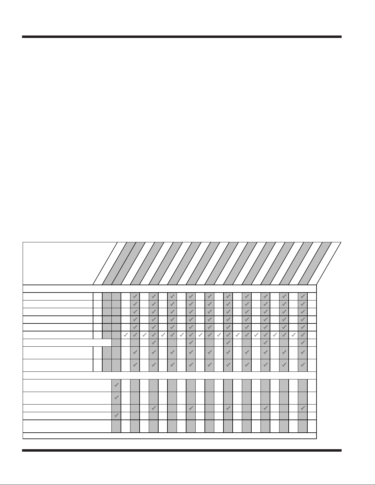
Maintenance Schedule
Maintenance
Schedule
o
#
Rotor Bearing
Drive Shaft Bearing
Cylinder End
Tire Spindle Tube
Wheel Axle
Oil Drive Chain
Check Gearbox Oil Level
Spindle Tube
(Outside Gauge Wheel Kit)
Wheel Axle
(Outside Gauge Wheel Kit)
Inspect for Loose, Missing, or Worn
Components.
Inspect Drive Belt, Hydraulic Hoses, &
Fittings
Inspect Drive Chain
Inspect Safety Decals
Check Tire Pressure (15 - 18 PSI)
(Outside Gauge Wheel Kit)
^Grease until fresh grease is visible.
21
11
2^
2^
2^
1
2^
2^
s
n
s
o
i
p
t
a
m
c
u
o
P
L
f
f
o
a
#
D
s
s
r
r
u
u
o
o
H
H
5
y
l
i
0
2
5
t
A
Grease & Lubrication: See Lubrication Section
7
t
t
A
A
s
s
s
s
s
s
s
s
s
s
s
s
s
s
s
s
r
r
r
r
r
r
r
r
r
r
r
r
r
r
s
r
u
u
u
u
u
u
u
u
u
u
u
u
u
o
o
o
o
o
o
o
o
o
o
o
H
H
H
H
H
H
H
H
H
0
5
0
5
0
5
5
0
2
5
7
1
1
t
A
1
t
t
A
A
0
1
2
t
t
A
A
0
2
5
2
2
t
t
A
A
H
5
0
7
0
2
3
t
t
A
A
A
o
H
H
5
0
2
5
3
3
t
t
t
A
A
u
o
o
H
H
5
0
7
0
3
4
4
t
t
A
A
r
u
u
o
o
H
H
5
0
2
5
4
4
t
t
A
A
s
r
r
u
u
o
o
H
H
5
0
y
7
l
0
r
5
a
t
e
A
Y
Inspection
Service - 18
Page 19
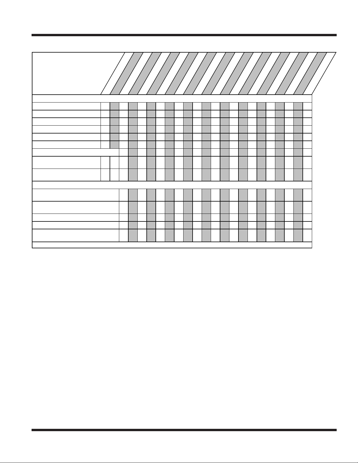
Maintenance Checklist
SERVICE
Maintenance
Checklist
Rotor Bearing
Drive Shaft Bearing
Cylinder End
Tire Spindle Tube
Wheel Axle
Oil Drive Chain
Check Gearbox Oil Level
Spindle Tube
(Outside Gauge Wheel Kit)
Wheel Axle
(Outside Gauge Wheel Kit)
Inspect for Loose, Missing, or Worn
Components.
Inspect Drive Belt, Hydraulic Hoses, &
Fittings
Inspect Drive Chain
Inspect Safety Decals
Check Tire Pressure (15 - 18 PSI)
(Outside Gauge Wheel Kit)
^Grease until fresh grease is visible.
21
11
2^
2^
2^
1
2 ^
2 ^
s
n
s
s
o
i
p
t
a
m
c
u
o
P
L
f
f
o
#
2
o
t
#
A
Grease & Lubrication: See Lubrication Section
s
r
r
u
u
o
o
H
H
5
0
5
5
7
t
t
A
A
u
o
H
A
s
r
o
H
0
0
1
t
A
Inspection
s
s
s
s
s
s
s
s
s
s
s
s
s
s
s
s
r
r
r
r
r
r
r
r
r
r
r
r
r
r
u
u
u
u
u
u
u
u
u
u
u
u
o
o
o
o
o
o
o
o
o
H
H
H
H
H
H
H
5
0
5
0
5
2
5
7
1
1
t
t
A
0
1
2
t
t
A
A
0
2
5
2
2
t
t
A
A
H
5
0
7
0
2
3
t
t
A
A
A
o
H
H
5
0
2
5
3
3
t
t
t
A
A
u
o
o
H
H
5
0
7
0
3
4
4
t
t
A
A
r
u
u
o
o
H
H
5
0
2
5
7
4
4
t
t
A
A
s
r
r
u
u
o
o
H
H
5
0
y
l
0
r
5
a
t
e
A
Y
Service - 19
Page 20

SPECIFICATIONSSPECIFICATIONS
Dimensions
Overall Height . . . . . . . . . . . . . . . . . . . . . . . . . . . . . . . . 18-1/2 inches (47 cm)
Overall Length . . . . . . . . . . . . . . . . . . . . . . . . . . . . . . . 46-1/2 inches (118 cm)
Overall Width . . . . . . . . . . . . . . . . . . . . . . . . . . . . . . . 60-1/2 inches (154 cm)
Weight . . . . . . . . . . . . . . . . . . . . . . . . . . . . . . . . . . . . . 240 pounds (109 kg)
Broom Width . . . . . . . . . . . . . . . . . . . . . . . . . . . . . . . . . . 54 inches (137 cm)
Broom Width (Angled) . . . . . . . . . . . . . . . . . . . . . . . . . . . . . 50 inches (127 cm)
Broom Diameter . . . . . . . . . . . . . . . . . . . . . . . . . . . . . . . . 16 inches (40.5 cm)
Broom Speed . . . . . . . . . . . . . . . . . . . . . . . . . . . . . . . . . . . . . . .265 RPM
Broom Travel . . . . . . . . . . . . . . . . . . . . . . . . . . . . . . . 1100 ft/min (335 m/min)
Features
Hydraulic angle left and right from driver’s seat.
Adjustable gauge wheels
Corner-less frame on left side
Specications - 20
Page 21

Blank Page
Page 22
PARTS
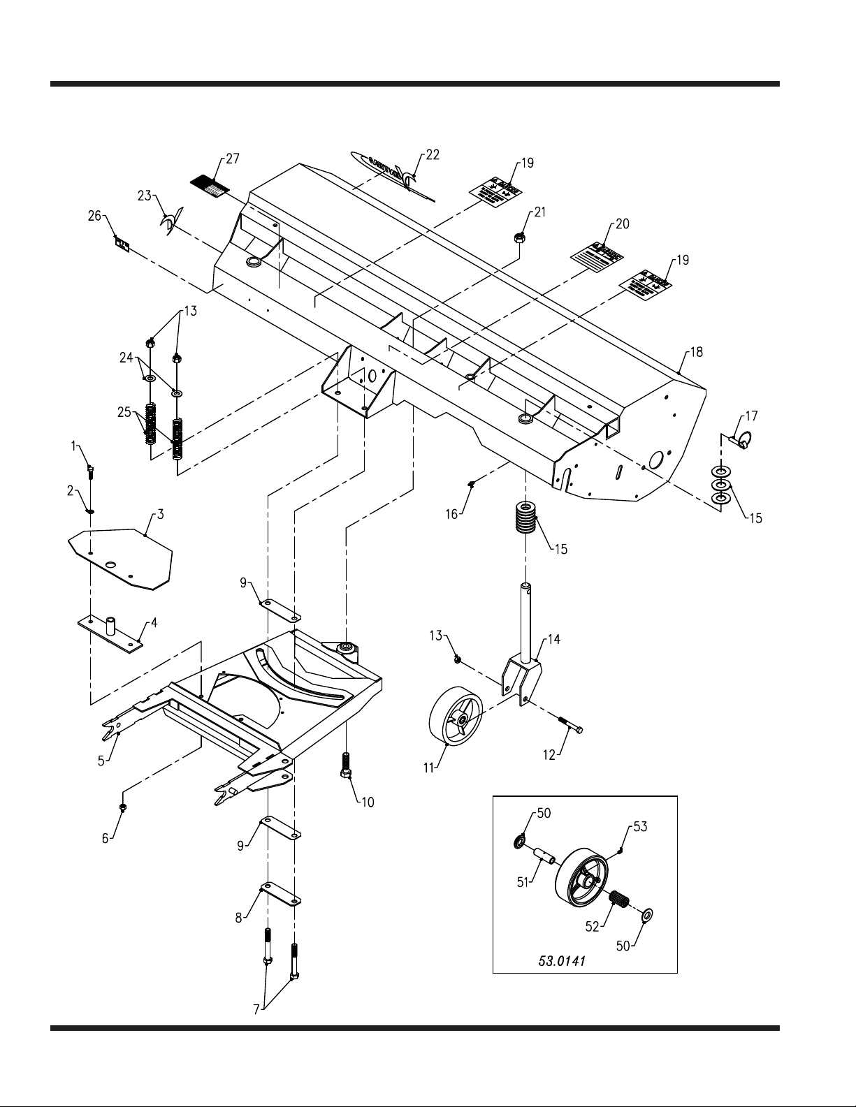
ILLUSTRATED DRAWING
Main Frame & Hitch
Illustrated Parts - 22
Use only original Ventrac
replacement parts.
Page 23

PARTS
Main Frame & Hitch
REF. PART NO. DESCRIPTION QTY.
1 .........90.0608 ....................BOLT, 3/8-16 USS X 1 ...................................................... 2
2 .........94.06 ......................WASHER, FLAT 3/8 USS ................................................... 2
3 .........44.0186 ....................RUBBER, BELT IDLER COVER ............................................. 1
4 .........64.0891 ....................BRACKET, BELT IDLER .................................................... 1
5 .........62.0910 ....................FRAME, MAIN HITCH ..................................................... 1
6 .........99.A06 .....................LOCKNUT, STOVER 3/8-16 USS ............................................ 2
7 .........90.0832 ....................BOLT, 1/2-13 USS X 4 ...................................................... 2
8 .........64.0884 ....................BRACKET, BACKER PLASTIC SLIDE ........................................ 1
9 .........44.0183 ....................SLIDE, 1/16 X 1-1/2 X 5 HDPE ............................................... 2
10 ........90.1018 ....................BOLT, 5/8-11 USS X 2 1/4 ................................................... 1
11 ......... 53.0098 ....................WHEEL, CASTER 6 X 2 (Serial # 1001-1221) ................................... 2
11 ......... 53.0141 ....................WHEEL, CASTER 6 X 2 (Serial # 1222-) ....................................... 2
12 ........90.0828 ....................BOLT, 1/2-13 USS X 3 1/2 ................................................... 2
13 ........99.A08 .....................LOCKNUT, STOVER 1/2-13 USS ............................................ 4
14 ........50.0162 ....................FRAME, CASTER WHEEL .................................................. 2
15 ........95.16 ......................WASHER, FLAT 1 SAE .................................................... 50
16 ........29.GF0001 .................GREASE FTG, 1/4 SAE ST ................................................. 2
17 ........03.0005 ....................PIN, LINCH .............................................................. 2
18 ........62.0909 ....................FRAME, MAIN BRUSH ..................................................... 1
19 ........00.0102 ....................DECAL, DANGER-PINCHING HAZARD ...................................... 2
20 ........00.0101 ....................DECAL, HAZARD-MOVING PART ........................................... 1
21 ........99.A10 .....................LOCKNUT, STOVER 5/8-11 USS ............................................. 1
22 ........00.0189 ....................DECAL, VENTRAC ORBITAL ............................................... 1
23 ........00.0192 ....................DECAL, V-DECAL DIE CUT BLUE ........................................... 1
24 ........94.08 ......................WASHER, FLAT 1/2 USS ................................................... 2
25 ........41.0062 ....................SPRING, 1.14 OD X 2.84 ZP ................................................ 2
26 ........00.0100 ....................DECAL, MADE IN USA ..................................................... 1
27 ........00.0217 ....................DECAL, WARNING READ OWNERS MAN .................................... 1
50 ........55.0074 ....................BEARING, RETAINER 3/4” ................................................. 2
51 ........85.B0089 ...................BUSHING, 1/2ID X 3/4OD X 2.406 ............................................ 1
52 ........55.0073 ....................BEARING, ROLLER 1-13/16” LONG .......................................... 1
53 ........29.GF0001 .................GREASE FTG, 1/4 SAE ST ................................................. 1
Illustrated Parts - 23
Use only original Ventrac
replacement parts.
Page 24
PARTS
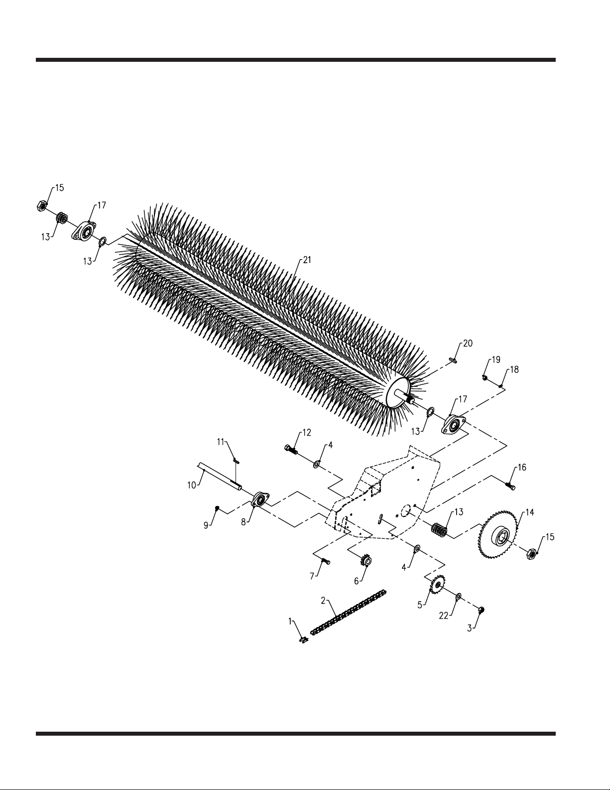
ILLUSTRATED DRAWING
Brush Assembly & Drive Chain
Illustrated Parts - 24
Use only original Ventrac
replacement parts.
Page 25

PARTS
Brush Assembly & Drive Chain
REF. PART NO. DESCRIPTION QTY.
1 .........81.0056 ....................LINK, CONN. #40 ......................................................... 1
2 .........81.0137 ....................CHAIN, ROLLER #40 X 43” LB540 ........................................... 1
3 .........99.A08 .....................LOCKNUT, STOVER 1/2-13 USS ............................................ 1
4 .........94.08 ......................WASHER, FLAT 1/2 USS ................................................... 2
5 .........83.4017E08 .................SPROCKET, IDLER #40 17-T. . . . . . . . . . . . . . . . . . . . . . . . . . . . . . . . . . . . . . . . . . . . . . . . 1
6 .........83.H401012 ................SPROCKET, #40 10-T HRD ................................................. 1
7 .........90.0508 ....................BOLT, 5/16-18 USS X 1 ..................................................... 2
8 .........55.FB16012-1 ...............BEARING, FLANGE BLOCK 3/4” ............................................ 1
9 .........99.SF05 ...................NUT, SRF 5/16-18 USS ..................................................... 2
10 ........80.0316 ....................SHAFT, BROOM DRIVE .................................................... 1
11 ......... 85.K0310 ...................KEY, 3/16 X 1 1/4 .......................................................... 1
12 ........90.0814 ....................BOLT, 1/2-13 USS X 1 3/4 ................................................... 1
13 ........99.B0015 ...................WASHER, MACH 1” 10 GA ................................................. 9
14 ........83.404016 ..................SPROCKET, #40 40-T 1” BORE .............................................. 1
15 ........99.E0063 ...................NUT, JAM 1-14 SAE GR 5 .................................................. 2
16 ........90.0708 ....................BOLT, 7/16-14 USS X 1 ..................................................... 2
17 ........55.FB23016-1 ...............BEARING, FLANGE BLOCK 1” .............................................. 2
18 ........96.07 ......................WASHER, LOCK 7/16 ...................................................... 2
19 ........92.07 ......................NUT, 7/16-14 USS ......................................................... 2
20 ........85.K0408 ...................KEY, 1/4 X 1 .............................................................. 1
21 ........80.0317 ....................BRUSH, WELDMENT LB540 ................................................ 1
22 ........95.08 ......................WASHER, FLAT 1/2 SAE ................................................... 1
Illustrated Parts - 25
Use only original Ventrac
replacement parts.
Page 26
PARTS
ILLUSTRATED DRAWING
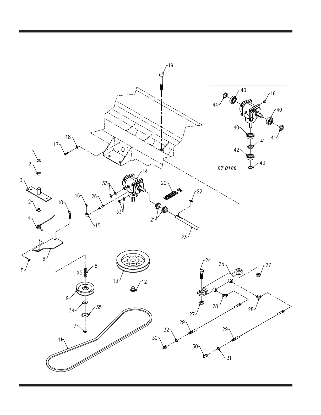
Belt Drive, Gearbox, & Hydraulics
Illustrated Parts - 26
Use only original Ventrac
replacement parts.
Page 27

PARTS
Belt Drive, Gearbox, & Hydraulics
REF. PART NO. DESCRIPTION QTY.
1 .........95.08 ......................WASHER, FLAT 1/2 SAE ................................................... 1
2 .........85.B0027 ...................BUSHING, 1/2 ID X 5/8 OD X 5/8 ............................................. 2
3 .........64.0891 ....................BRACKET, BELT IDLER .................................................... 1
4 .........41.0066 ....................SPRING, SINGLE TORSION LH ............................................. 1
5 .........02.CP0406 .................COTTER PIN, 1/8 X 3/4 .................................................... 1
6 .........40.0287 ....................ARM, IDLER ............................................................. 1
7 .........99.SF06 ...................NUT, SRF 3/8-16 USS ...................................................... 1
8 .........95.06 ......................WASHER, FLAT 3/8 SAE ................................................... 5
9 .........83.0037 ....................PULLEY, IDLER FLAT 4” X 3/8 ............................................... 1
10 ........90.0614 ....................BOLT, 3/8-16 USS X 1 3/4 (Serial # 1001-1507) .................................. 1
10 ........90.0616 ....................BOLT, 3/8-16 USS X 2 (Serial # 1508-) ......................................... 1
11 ......... 81.A065 ....................BELT, A65 ............................................................... 1
12 ........83.H12 ....................BUSHING, 3/4” H ......................................................... 1
13 ........83.BK80H ..................PULLEY, 8” H-BUSH ....................................................... 1
14 ........87.0186 ....................GEARBOX, CURTIS LB540 ................................................. 1
15 ........29.E9004G .................PIPE, ELBOW 90, 1/4 GALV ................................................ 1
16 ........29.P04 .....................PIPE, PLUG 1/4” SQ ...................................................... 2
17 ........90.0506 ....................BOLT, 5/16-18 USS X 3/4 ................................................... 4
18 ........95.05 ......................WASHER, FLAT 5/16 SAE .................................................. 4
19 ........90.1052 ....................BOLT, 5/8-11 USS X 6 1/2 ................................................... 1
20 ........87.0175 ....................CHAIN, COUPLING-#40 DBL W/LINK. . . . . . . . . . . . . . . . . . . . . . . . . . . . . . . . . . . . . . . . . 1
21 ........87.0174 ....................COUPLING, HALF--#40 SPROCKET ......................................... 2
22 ........85.K0310 ...................KEY, 3/16 X 1 1/4 .......................................................... 3
23 ........80.0316 ....................SHAFT, BROOM DRIVE .................................................... 1
24 ........90.1016 ....................BOLT, 5/8-11 USS X 2 ...................................................... 1
25 ........23.0108 ....................CYLINDER, 1-1/2” X 8” (Serial # 1001-1074) .................................... 1
25 ........23.0129 ....................CYLINDER, 1-1/2” X 8” STEERING (Serial # 1075-) .............................. 1
26 ........29.N0412G .................PIPE, NIPPLE 1/4 X 1 1/2 GALV ............................................. 1
27 ........99.A10 .....................LOCKNUT, STOVER 5/8-11 USS ............................................. 2
28 ........25.2501-06-04 ...............FITTING, 90 ME 3/8 X 1/4 (Serial # 1001-1074) .................................. 2
28 ........25.6801-06-06 ...............FITTING, 90 ME 3/8 X 3/8 (Serial # 1075-) ...................................... 2
29 ........20.0169 ....................HOSE, 1/4X38.00 SAE 100R17 AR ........................................... 2
30 ........23.0104 ....................COUPLER, QUICK MALE 1/4 ............................................... 2
31 ........05.0117 ....................WASHER, .544ID X .817 X.14 YEL ........................................... 1
32 ........05.0116 ....................WASHER, .544ID X .817 X.14 RED ........................................... 1
33 ........95.05 ......................WASHER, FLAT 5/16 SAE (Serial # 1400-) ..................................... 4
34 ........95.06 ......................WASHER, FLAT 3/8 SAE (Serial # 1001-1507) .................................. 1
34 ........99.G0014 ..................WASHER, 3/8 USS FW .165 THK (Serial # 1508-2155) ........................... 1
35 ........60.1056 ....................COVER, PULLEY (Serial # 1508-) ............................................ 1
40 ........55.0085 ....................BEARING, BALL 25MM X 52MM (Open) ....................................... 3
41 ........89.0088 ....................SEAL, SHAFT ............................................................2
42 ........55.0086 ....................BEARING, BALL 25MM X 52MM (Sealed) ...................................... 1
43 ........04.0031 ....................RETAINING RING, CURTIS GEARBOX ....................................... 1
44 ........89.0089 ....................SEAL, EXPANSION PLUG .................................................. 1
Illustrated Parts - 27
Use only original Ventrac
replacement parts.
Page 28
PARTS
ILLUSTRATED DRAWING
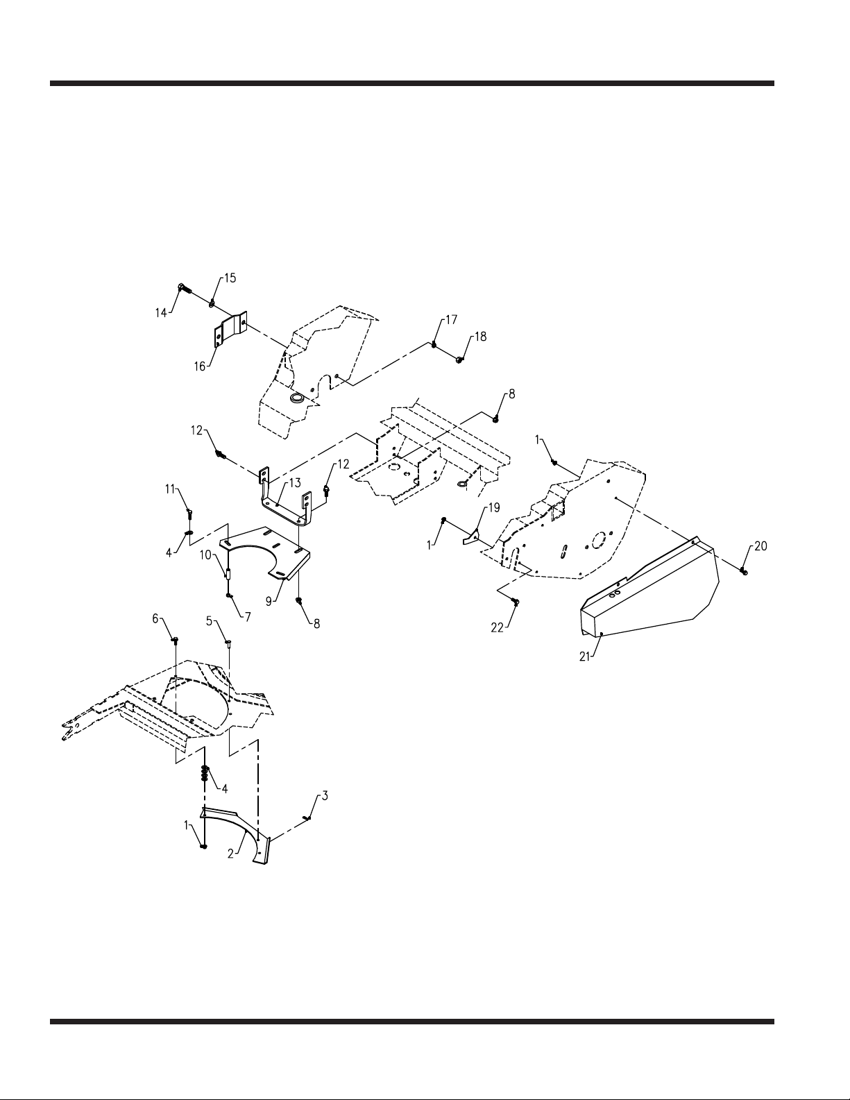
Shields & Belt Retainer
Illustrated Parts - 28
Use only original Ventrac
replacement parts.
Page 29

PARTS
Shields & Belt Retainer
REF. PART NO. DESCRIPTION QTY.
1 .........99.SF04 ...................NUT, SRF 1/4-20 USS ...................................................... 7
2 .........60.0782 ....................BRACKET, BELT IDLER SPRING GD. . . . . . . . . . . . . . . . . . . . . . . . . . . . . . . . . . . . . . . . . 1
3 .........02.HP0313 .................HAIRPIN, 3/32 X 1-5/8 ..................................................... 1
4 .........95.04 ......................WASHER, FLAT 1/4 SAE ...................................................11
5 .........03.0406 ....................CLEVIS PIN, 1/4 X 3/4 ..................................................... 1
6 .........90.0406 ....................BOLT, 1/4-20 USS X 3/4 .................................................... 2
7 .........99.A04 .....................LOCKNUT, STOVER 1/4-20 USS ............................................ 3
8 .........99.SF05 ...................NUT, SRF 5/16-18 USS ..................................................... 6
9 .........64.0964 ....................BRACKET, BELT TUBE GUIDE ............................................. 1
10 ........64.0965 ....................PIPE, SCH 80 1/4 X 1-1/4L .................................................. 3
11 ......... 90.0414 ....................BOLT, 1/4-20 USS X 1 3/4 ................................................... 3
12 ........99.SF0506 .................BOLT, SRF 5/16-18 USS X 3/4 .............................................. 6
13 ........64.0963 ....................BRACKET, BELT RETAINER MOUNT ........................................ 1
14 ........90.0710 ....................BOLT, 7/16-14 USS X 1 1/4 .................................................. 2
15 ........95.07 ......................WASHER, FLAT 7/16 SAE .................................................. 2
16 ........64.0954 ....................SHIELD, SHAFT COVER LEFT SIDE ......................................... 1
17 ........96.07 ......................WASHER, LOCK 7/16 ...................................................... 2
18 ........92.07 ......................NUT, 7/16-14 USS ......................................................... 2
19 ........64.0989 ....................PLATE, HOLE SHAFT COVER .............................................. 1
20 ........99.SF0404-1 ................BOLT, SMF 1/4-20 X 1/2 .................................................... 4
21 ........60.0815 ....................SHIELD, CHAIN COVER ................................................... 1
22 ........99.SF0404-1 ................BOLT, SMF 1/4-20 X 1/2 .................................................... 1
Illustrated Parts - 29
Use only original Ventrac
replacement parts.
Page 30
PARTS
ILLUSTRATED DRAWING
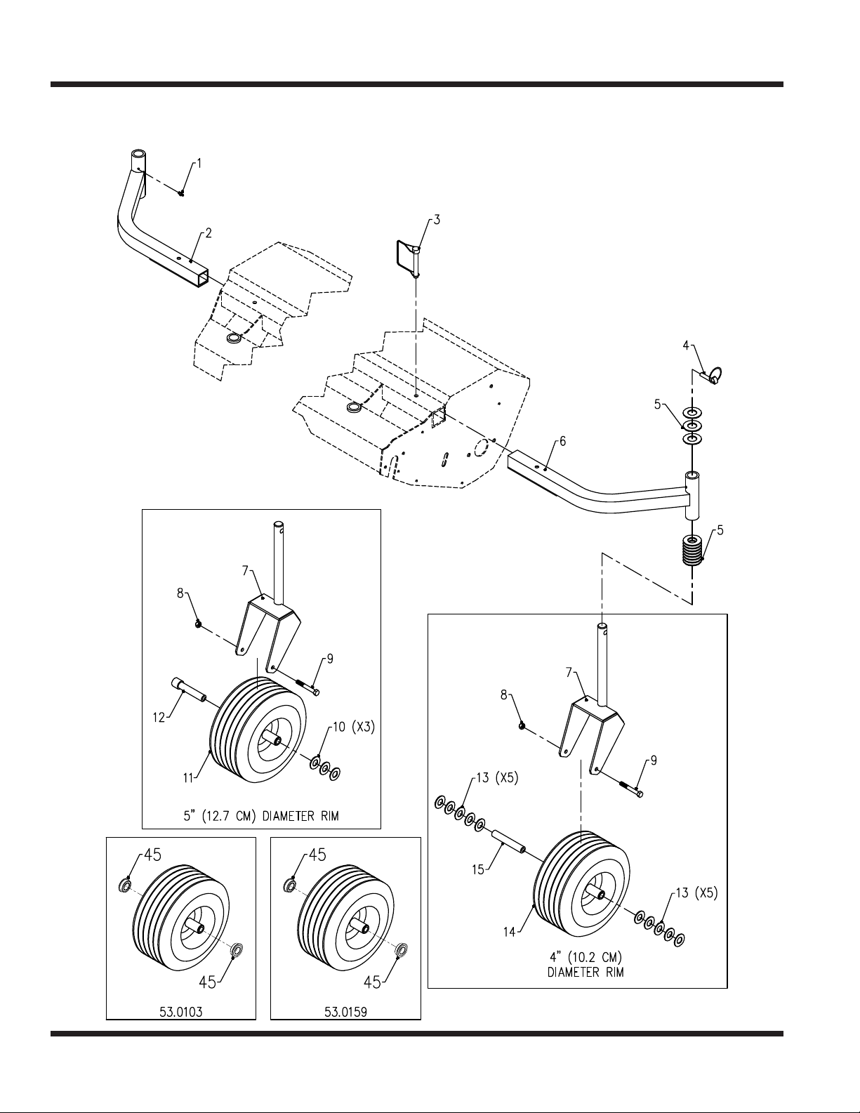
39.35403 Outside Gauge Wheel Kit
Illustrated Parts - 30
Use only original Ventrac
replacement parts.
Page 31

PARTS
39.35403 Outside Gauge Wheel Kit
REF. PART NO. DESCRIPTION QTY.
1 .........29.GF0001 .................GREASE FTG, 1/4 SAE ST ................................................. 2
2 .........64.0960 ....................FRAME, OUTSIDE GAUGE WHEEL LH ....................................... 1
3 .........03.0003 ....................PIN, SAFETY SNAP 3/8 X 2 1/2 .............................................. 2
4 .........03.0005 ....................PIN, LINCH .............................................................. 2
5 .........95.16 ......................WASHER, FLAT 1 SAE .................................................... 58
6 .........64.0959 ....................FRAME, OUTSIDE GAUGE WHEEL RH ...................................... 1
7 .........50.0165 ....................FRAME, CASTER YOKE ................................................... 1
8 .........99.A06 .....................LOCKNUT, STOVER 3/8-16 USS ............................................ 2
9 .........90.0644 ....................BOLT, 3/8-16 USS X 5 1/2 ................................................... 2
10 ........95.12 ......................WASHER, FLAT 3/4 SAE ................................................... 6
11 ......... 53.0103 ....................WHEEL, CASTER 11 X 4-5 X 3/4 ............................................. 2
12 ........50.0166 ....................AXLE, TUBE .740/.745 DIA .................................................. 2
13 ........95.12 ......................WASHER, FLAT 3/4 SAE .................................................. 20
14 ........53.0159 ....................WHEEL, CASTER 11 X 4-4 X 3/4 ............................................. 2
15 ........50.0191 ....................TUBE, AXLE-WHEEL LB CASTER ........................................... 2
45 ........55.0060 ....................BEARING, DOUBLE-SEALED ............................................... 2
Illustrated Parts - 31
Use only original Ventrac
replacement parts.
Page 32
PARTS
ILLUSTRATED DRAWING
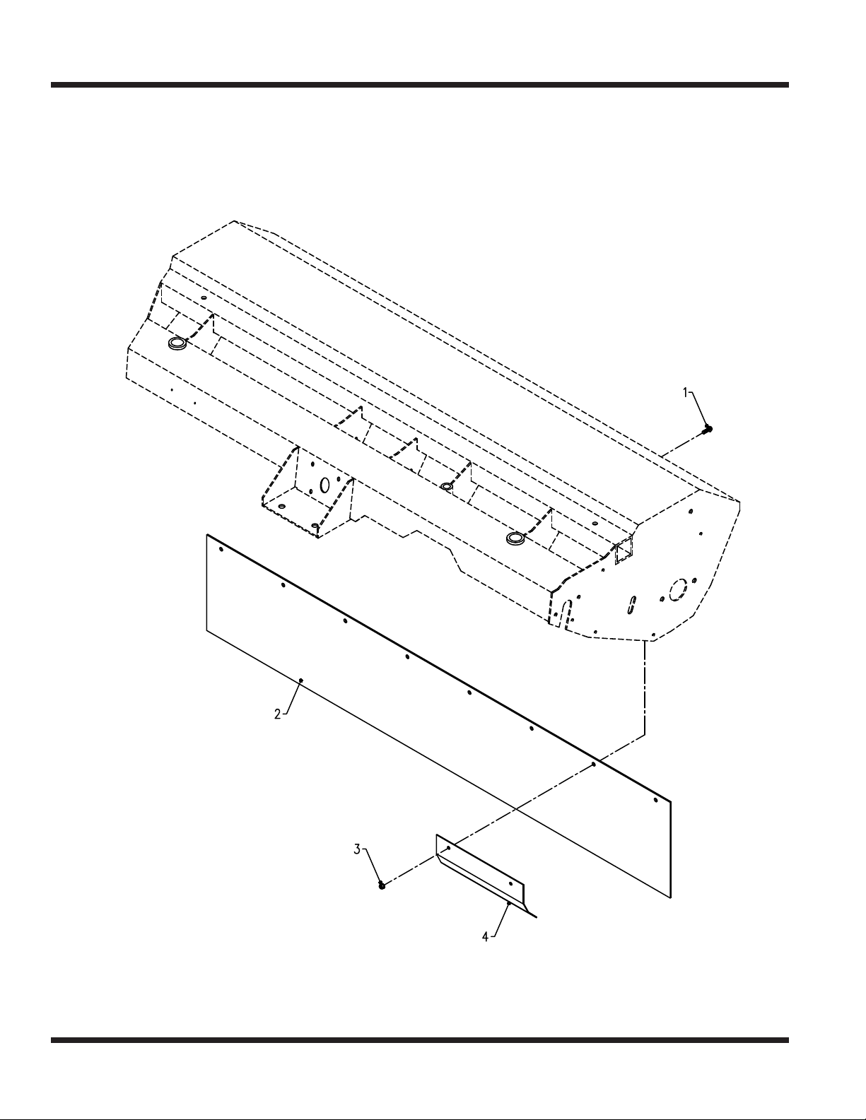
70.8029 Front Belting Curtain Kit
Illustrated Parts - 32
Use only original Ventrac
replacement parts.
Page 33

PARTS
70.8029 Front Belting Curtain Kit
REF. PART NO. DESCRIPTION QTY.
1 .........99.SF0406-1 ................BOLT, SMF 1/4-20 X 3/4 .................................................... 8
2 .........44.0202 ....................BELTING, FRONT 10 X 56L ................................................. 1
3 .........99.SF04 ...................NUT, SRF 1/4-20 USS ...................................................... 8
4 .........64.1050 ....................CLAMP, FRONT BELTING 10-1/2L ........................................... 4
Illustrated Parts - 33
Use only original Ventrac
replacement parts.
Page 34
WARRANTY
LIMITED WARRANTY - VENTRAC COMMERCIAL EQUIPMENT
Venture Products, Inc., (henceforth referred to as V.P.I.) warrants on the terms and conditions herein, that it will
repair, replace, or adjust any part manufactured by Venture Products Inc., and found by Venture Products, Inc., to be
defective in material and/or workmanship during the applicable warranty term.
All Ventrac commercial equipment purchased and registered on or after January 1, 2019 will carry a 2-year
commercial warranty. The warranty period begins on the date of original customer purchase:
Ventrac Commercial Equipment Warranty Term
2100 SSV & Attachments 2-year
3000 Series Tractors & Attachments 2-year
4000 Series Tractors & Attachments 2-year
All Ventrac add-on kits and accessories such as: 3-point hitch, 12V front & rear power outlets, foot pedal, dual wheel
kit, etc., will be covered under the above warranty periods provided they are installed by an Authorized Ventrac
Dealer. This warranty may be transferred and will carry the remainder of the warranty starting from the original
purchase/registration date with the dealership and/or V.P.I.
The engine warranty is covered by its respective engine manufacturer. Please refer to the engine manufacturer’s
warranty statement that is included in the owner’s manual.
For warranty consideration on Ventrac commercial equipment, including any defective part, must be returned to an
Authorized Ventrac Dealer within the warranty period. The warranty shall extend to the cost to repair or replace (as
determined by V.P.I.) the defective part. The expense of pickup and delivery of equipment, service call drive time
or any transportation expense incurred for warranty repair is the sole responsibility of the owner and is not covered
under warranty by Ventrac and/or V.P.I. Ventrac and V.P.I.’s responsibility in respect to claims is limited to making the
required repairs or replacements, and no claim of breach of warranty shall be cause for cancellation or rescission of
the contract of sale of any Ventrac equipment. Proof of purchase may be required by the dealer to substantiate any
warranty claim. Only warranty work performed and submitted by an Authorized Ventrac Dealer may be eligible for
warranty credit.
This warranty extends only to Ventrac commercial equipment operated under normal conditions and properly serviced
and maintained. The warranty expressly does NOT cover: (a) any defects, damage or deterioration due to normal
use, wear and tear, or exposure; (b) normal maintenance services, such as cleaning, lubrication, oil change; (c)
replacement of service items, such as oil, lubricants, spark plugs, belts, rubber hoses, bearings or other items subject
to normal service replacement; (d) damage or defects arising out of, or relating to abuse, misuse, neglect, alteration,
negligence or accident; (e) repair or replacement arising from operation of, or use of the equipment which is not in
accordance with operating instructions as specied in the operator’s manual or other operational instructions provided
by V.P.I.; (f) repair or replacement arising as a result of any operation from Ventrac equipment that has been altered
or modied so as to, in the determination of V.P.I., adversely aect the operation, performance or durability of the
equipment or that has altered, modied or aected the equipment so as to change the intended use of the product; (g)
repair or replacement necessitated by the use of parts, accessories or supplies, including gasoline, oil or lubricants,
incompatible with the equipment or other than as recommended in the operator’s manual or other operational
instructions provided by V.P.I.; (h) repairs or replacements resulting from parts or accessories which have adversely
aected the operation, performance or durability of the equipment; or (i) damage or defects due to or arising out of
repair of Ventrac equipment by person or persons other than an authorized Ventrac service dealer or the installation of
parts other than genuine Ventrac parts or Ventrac recommended parts.
Warranty - 34
Page 35

WARRANTY
LIMITED WARRANTY - VENTRAC COMMERCIAL EQUIPMENT
The sole liability of V.P.I. with respect to this warranty shall be the repair and replacement as set forth herein. V.P.I.
shall have no liability for any other cost, loss, or damage. In particular V.P.I shall have no liability or responsibility for:
(i) expenses relating to gasoline, oil, lubricants; (ii) loss, cost or expense relating to transportation or delivery of turf
equipment from the location of owner or location where used by owner to or from any Authorized Ventrac Dealer;
(iii) travel time, overtime, after hours’ time or other extraordinary repair charges or charge relating to repairs or
replacements outside of normal business hours at the place of business of an Authorized Ventrac Dealer; (iv) rental of
like or similar replacement equipment during the period of any warranty repair or replacement work; (v) any telephone
or telegram charges; (vi) loss or damage to person or property other than that covered by the terms of this warranty;
(vii) any claims for lost revenue, lost prot or additional cost or expense incurred as a result of a claim of breach of
warranty; or (viii) attorney’s fees.
The remedies of buyer set forth herein are exclusive and are in lieu of all other remedies. The liability of V.P.I.,
whether in contract, tort, under any warranty, or otherwise, shall not extend beyond its obligation as set forth herein.
V.P.I. shall not be liable for cost of removal or installation nor shall V.P.I. be responsible for any direct, indirect, special
or consequential damages of any nature. In no event shall V.P.I. be liable for any sum in excess of the price received
for the goods for which liability is claimed.
There are no representations or warranties which have been authorized to the buyer of the Ventrac commercial
equipment other than set forth in this warranty. Any and all statements or representations made by any seller of this
equipment, including those set forth in any sales literature or made orally by any sales representative, are superseded
by the terms of this warranty. Any armation of fact or promise made by V.P.I. or any of its representatives to the
buyer which relates to the goods that are the subject to this warranty shall not be regarded as part of the basis of the
bargain and shall not be deemed to create any express warranty that such goods shall conform to the armation or
promise.
No employee, distributor, or representative is authorized to change the foregoing warranties in any way or grant any
other warranty on behalf of V.P.I.
Some states do not allow limitations on how long an implied warranty lasts or allow the exclusion on limitation of
incidental or consequential damages, so the above limitation or exclusion may not apply to you.
This warranty gives you specic legal rights, and you may also have other rights which vary from state to state.
This warranty applies to all Ventrac commercial equipment sold by Venture Products Inc.
Warranty - 35
 Loading...