

Page 1
OPERATOR’S MANUAL
VENTRAC 4100
Serial # 1502-
Revised 06/11/14
09.10050 Rev. 02
Page 2
A
B
C
328 East Water St.
PO Box 148
Orrville Oh 44667
www.ventrac.com
To the Owner
Contact Information and Product Identifi cation
If you need to contact an authorized Ventrac dealer for information on servicing your product,
always provide the product model and serial numbers.
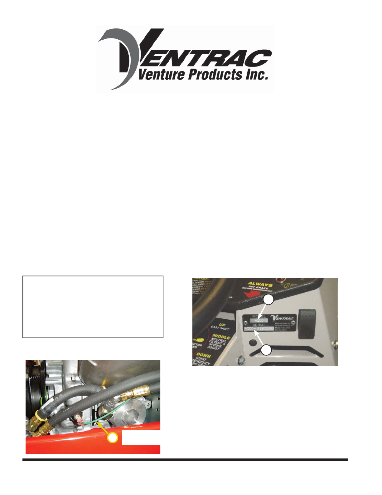
Please fi ll in the following information for future reference. See the picture(s) below to fi nd the
location of the identifi cation numbers. Record them in the spaces provided.
Date of Purchase: ________________________________________________________
Dealer: _________________________________________________________________
Dealer Address: __________________________________________________________
__________________________________________________________
Dealer Phone Number: ____________________________________________________
Dealer Fax Number: ______________________________________________________
Model # (A): ______________________
Serial # (B): ______________________
Affi x Part/Serial Number label here.
Engine Serial # (C): ___________________
Located on engine block next to
C
the remote oil fi lter adapter base.
A
B
Venture Products Inc. reserves the right to make changes in design or specifi cations without obligation to make
like changes on previously manufactured products.
2
Page 3
enture Products Inc. is pleased to provide you with
V
your new Ventrac! We hope that Ventrac equipment
will provide you with a ONE Tractor Solution.
Listed below are just some of the items that can
provide you versatility as you use your 4100.
Please visit our web site, or contact your authorized
Ventrac dealer for a complete list of items available for
your new power unit.
Item Description
Three Point Hitch 70.4063 Light Bar 70.4030
Dual Wheels (All Terrain Tires) 70.4067 Rear Counter Weight Bar 39.56116
Dual Wheels (Turf Tires) 70.4068 Rear Bumper 70.4045
Dual Wheels (Bar Tires) 70.4069 Slope Gauge Indicator 70.0109
Canopy 70.0098 12V Rear (4 Pin Socket & Power Outlet) 70.4087
Fold Down ROPS Roll Bar 70.2004 Front 12 Volt Switch & Plug 70.4039
Suspension Seat 47.0231 Backup Alarm 70.4083
Foot Pedal 39.56108 Electric PTO Remote 70.4078
Wheel Extensions 70.4098 Two -N-One Front Hitch 70.2001
Accessories
Cab 70.2006 ES220 Spreader 39.55500
SS300 Salt Spreader 70.2011 SS575 Salt Spreader 70.2010
Front Fenders 70.0099 3-3/8” Tachometer 70.0101
Foot Rests 70.0100 Weight Transfer 70.0104
Item Description
Aerator with Open Spoon Tine 39.55490 Snow Blower 39.55427
Aerator with Slitter/Slicer Tine 39.55492 Sod Cutter 39.55520
Aerator with Coring Tine 39.55494 Stump Grinder 39.55300
AeraVator (seeder kit available) 39.55460 Terra Rake - 52” 39.55431
Blade - 48” 39.55251 Tiller 39.55220
Blade - 60” 39.55252 Tough Cut Mower - 68” 39.55104
Blade - 72” 39.55253 Trencher 39.55455
Blower 39.55440 Turbine Blower 39.55340
Broom 39.55400 V-Blade 39.55271
Edger 39.55330 Versa-Loader 39.55600
Excavator - 30” 39.55236 Reel Mower - 74” 39.55130
Excavator - 48” 39.55230 Rear Discharge Mower - 60” 39.55120
Attachments
Finish Mower - 60” 39.55105 Contour Mower - 84” 39.55160
Finish Mower - 72” 39.55106 Collection Vacuum 39.55360
Finish Mower - 72” (6-1/2” offset) 39.55107
Generator - 15,000 Watt 39.55315
Power Rake 39.55435
Slip Scoop - 30” 39.55216
Slip Scoop - 48” 39.55210
Part Num
Part Number
ber
Item Description Part Number
Accessories
Item Description Part Number
Attachments
3
Page 4

TABLE OF CONTENTS
INTRODUCTION PAGE 7
Product Description ................................................................................................................................ 7
Why do I need an Operator’s Manual? ..................................................................................................7
Using Your Manual .................................................................................................................................8
Manual Glossary .................................................................................................................................... 8
SAFETY PAGE 9
Safety Decals .........................................................................................................................................9
General Safety Procedures .................................................................................................................. 11
Training Required ................................................................................................................................. 11
Personal Protective Equipment Requirements ....................................................................................11
Operating Safely .................................................................................................................................. 11
Preventing Accidents ............................................................................................................................ 12
Keep Riders Off ....................................................................................................................................12
Operating On Slopes ............................................................................................................................13
Roadway Safety ...................................................................................................................................13
Truck Or Trailer Transport ....................................................................................................................13
Maintenance .........................................................................................................................................14
Fuel Safety ...........................................................................................................................................14
Hydraulic Safety ...................................................................................................................................15
Roll-Over Protective Structure .............................................................................................................16
Operator Interlock Systems ..................................................................................................................17
OPERATIONAL CONTROLS PAGE 18
Operational Control Locations ..............................................................................................................19
Power Take Off (PTO) Switch (A) .........................................................................................................19
Ignition Key Switch (B) .........................................................................................................................19
Throttle (C) ...........................................................................................................................................19
Volt Gauge (D) ..................................................................................................................................... 19
Tachometer & Hour Meter (E) ..............................................................................................................19
Seat Belt Light (G) ................................................................................................................................19
Light Switch (H) .................................................................................................................................... 20
12 Volt Switches (I & J) ........................................................................................................................20
Choke (K) .............................................................................................................................................20
Selector Lever/Parking Brake (L) .........................................................................................................20
Belt Tension Lever (M) .........................................................................................................................20
Front Hitch Latch Lever (N) .................................................................................................................. 20
Front Hitch Lock (O) ............................................................................................................................. 20
Seat Slide Adjustment Lever (P) ..........................................................................................................20
High/Low Range Shift Handle (Q) ........................................................................................................ 20
Weight Transfer (R) .............................................................................................................................. 20
S.D.L.A. Lever (T & U) ......................................................................................................................... 21
Foot Pedal (V) ......................................................................................................................................21
12 Volt Rear Outlet & 4-Pin Socket (W) ...............................................................................................21
Auxiliary Hydraulic Quick Couplers (AA) .............................................................................................. 21
12 Volt 4-Pin Socket (BB) ..................................................................................................................... 21
Electric PTO Remote (5-Pin Socket) (CC) ...........................................................................................21
Seat Latch (DD) ...................................................................................................................................22
Seat Prop (EE) .....................................................................................................................................22
4
Page 5

TABLE OF CONTENTS
GENERAL OPERATION PAGE 23
Daily Inspection ....................................................................................................................................23
Starting the Engine ...............................................................................................................................23
Forward and Reverse ...........................................................................................................................23
Stopping the Power Unit ......................................................................................................................24
Detaching .............................................................................................................................................24
Operating Attachments .........................................................................................................................24
Front Hitch ............................................................................................................................................24
PTO Drive Belt & Pulley .......................................................................................................................24
Front Auxiliary Couplers ...................................................................................................... .................25
Weight Transfer (Optional Accessory) ..................................................................................................25
High/Low Range ...................................................................................................................................25
Turning Radius .....................................................................................................................................26
3 Point Hitch (Optional Accessory) .......................................................................................................26
12 Volt Auxiliary Outlets (Optional Accessory) .....................................................................................26
Operating On Slopes ............................................................................................................................26
SERVICE PAGE 28
Cleaning & General Maintenance ........................................................................................................28
Service & Maintenance ........................................................................................................................28
Lubrication Locations ...........................................................................................................................29
Checking Hydraulic Oil Level ...............................................................................................................30
Checking Rear Transaxle Oil ...............................................................................................................30
Changing Hydraulic Oil and Filter ........................................................................................................30
Servicing Closed Loop Hydrostatic Drive Circuit ..................................................................................30
Checking Engine RPM .........................................................................................................................31
Checking Engine Oil Level ...................................................................................................................31
Changing Engine Oil and Filter ............................................................................................................31
Servicing Air Filter Elements ...............................................................................................................32
Filling the Fuel Tank .............................................................................................................................33
Servicing Fuel Filter .............................................................................................................................33
Cleaning Engine Compartment
& Oil Cooler ..........................................................................................................................................34
Servicing battery ..................................................................................................................................34
Removing and Installing Battery ..........................................................................................................34
Cleaning Battery and Terminals ...........................................................................................................35
Using a Booster Battery .......................................................................................................................35
Changing the Headlight Bulb ...............................................................................................................36
Changing the Taillights .........................................................................................................................36
Changing the Fuses .............................................................................................................................36
Inspection of PTO Belt .........................................................................................................................37
PTO Belt Replacement ........................................................................................................................37
Parking Brake Adjustment ....................................................................................................................38
Neutral Adjustment ...............................................................................................................................38
Recommended Tire Pressure ..................................................................................................... .........38
5
Page 6

TABLE OF CONTENTS
MAINTENANCE CHART PAGE 39
Ventrac 4100 Maintenance Schedule ..................................................................................................39
Ventrac 4100 Maintenance Checklist ...................................................................................................40
TROUBLESHOOTING PAGE 41
Engine ..................................................................................................................................................41
Electrical ...............................................................................................................................................42
Hydraulic ..............................................................................................................................................42
Power unit ............................................................................................................................................42
SPECIFICATIONS PAGE 43
Electrical ...............................................................................................................................................43
Power Train ..........................................................................................................................................43
Controls & instrument Panel ................................................................................................................43
Other features ......................................................................................................................................43
Dimensions ..........................................................................................................................................44
Fluid Capacities ....................................................................................................................................44
WARRANTY PAGE 45
6
Page 7

INTRODUCTION
Product Description
• The 4100 is a unique all-wheel-drive power unit that distributes its weight to four equal sized fl otation
tires for excellent control, traction, stability, maneuvering, and braking.
• Performance is enhanced by a sturdy, articulated chassis which oscillates to conform to ground contour
and turns with ease via hydraulic power steering.
• The hydrostatic transmission drive is controlled with Ventrac’s patented S.D.L.A. control, which is
located next to the operator, allowing for easy control of Speed, Direction, Lift, and Auxiliary functions
with one hand.
• The high/low range selector lever enables the operator to shift both transaxles between high and low
range with a single lever.
• The 4100 is equipped with the quick and effi cient Ventrac Mount System. This allows you to attach over
30 commercial grade attachments in about a minute or less and requires no tools.
Why do I need an Operator’s Manual?
This manual has been created to help you gain the important knowledge of what is needed to safely operate, maintain, and service your power unit. It is divided into sections for convenient reference of the appropriate section.
You must read and understand the operator’s manual for each piece of Ventrac equipment you own. Reading the operator’s manual will help you become familiar with each specifi c piece of equipment. Under-
standing the operator’s manual will help you, as well as others, avoid personal injury and/or damage to
the equipment. Keep this manual with the power unit at all times. Store the manual in the manual holder
located in the storage box to the right of the operator’s seat. The manual should remain with the power unit
even if it is sold. If this manual becomes damaged or unreadable, it should be replaced immediately. Contact your local Ventrac dealer for a replacement.
When using a Ventrac attachment, be sure to read and follow the safety and operating instructions of both
the power unit and the attachment being used to ensure the safest operation possible.
The information in this manual provides the operator with the safest procedures to operate the power unit
while getting the maximum use out of the unit. Failure to follow the safety precautions listed in this manual
may result in personal injury and/or damage to the equipment.
Introduction - 7
Page 8
INTRODUCTION
Using Your Manual
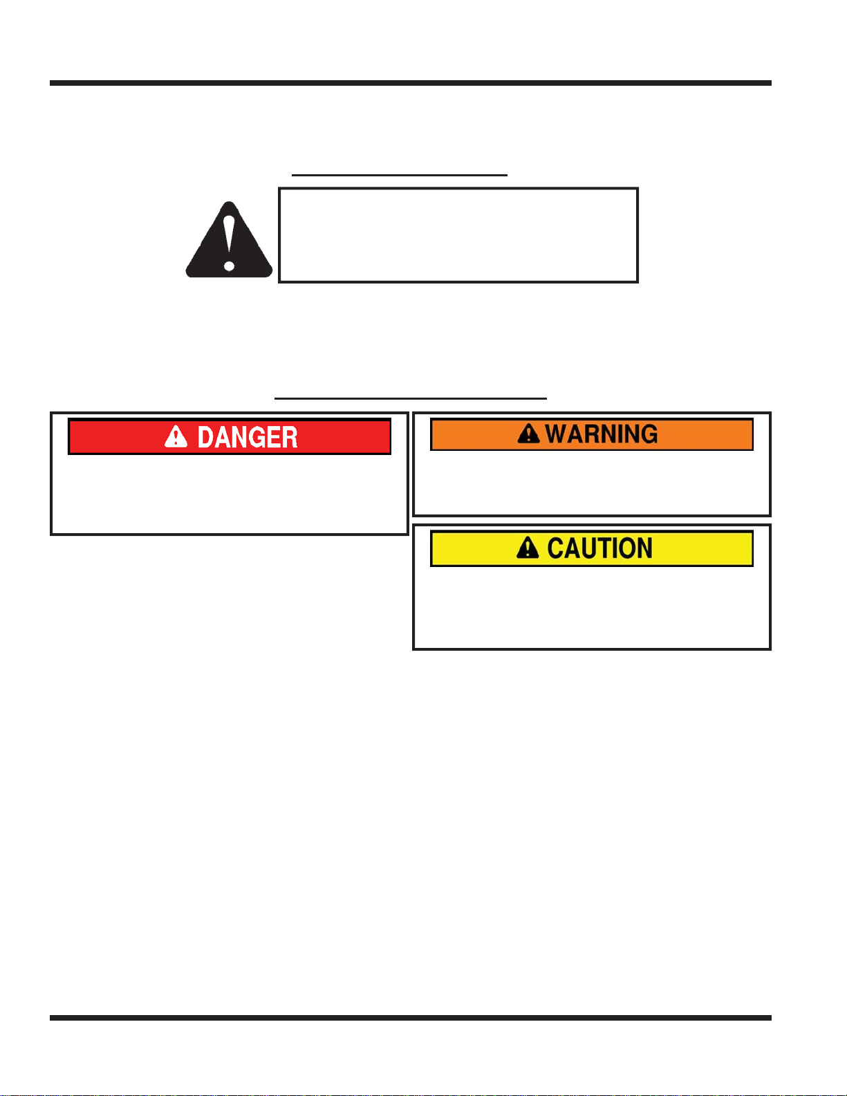
Throughout this manual, you will encounter special messages and symbols that identify potential safety
concerns to help you as well as others avoid personal injury or damage to the equipment.
SYMBOL DEFINITIONS
ATTENTION
This symbol identifi es potential health and
safety hazards. It marks safety precautions.
Your safety and the safety of others is involved.
There are three signal words that describe the level of safety concern: Danger, Warning, and Caution.
Safety should always be the #1 priority when working on or operating equipment. Accidents are more likely
to occur when proper operating procedures are not followed or inexperienced operators are involved.
Note: Right-Hand and Left-Hand orientations may be referred to at different places throughout this manual.
Right-Hand and Left-Hand is determined as if sitting on the power unit seat facing forward.
SIGNAL WORD DEFINITIONS
Indicates an imminently hazardous situation
which, if not avoided, will result in death or
serious injury. This signal word is limited to the
most extreme cases.
Indicates a potentially hazardous situation
which, if not avoided, could result in death or
serious injury.
Indicates a potentially hazardous situation
which, if not avoided, may result in minor or
moderate injury and/or property damage. It may
also be used to alert against unsafe practices.
Manual Glossary
Power Unit A Ventrac tractor or other Ventrac engine powered device that may be operated by itself or
with an attachment or accessory.
Attachment A piece of Ventrac equipment that requires a Power Unit for operation.
Accessory A device that attaches to a Power Unit or Attachment to extend its capabilities.
Machine Describes any “Attachment” or “Accessory” that is used in conjunction with a power unit.
Introduction - 8
Page 9
SAFETY
D
C
H
G
A
B
F
I
E
J
SAFETY
Safety Decals
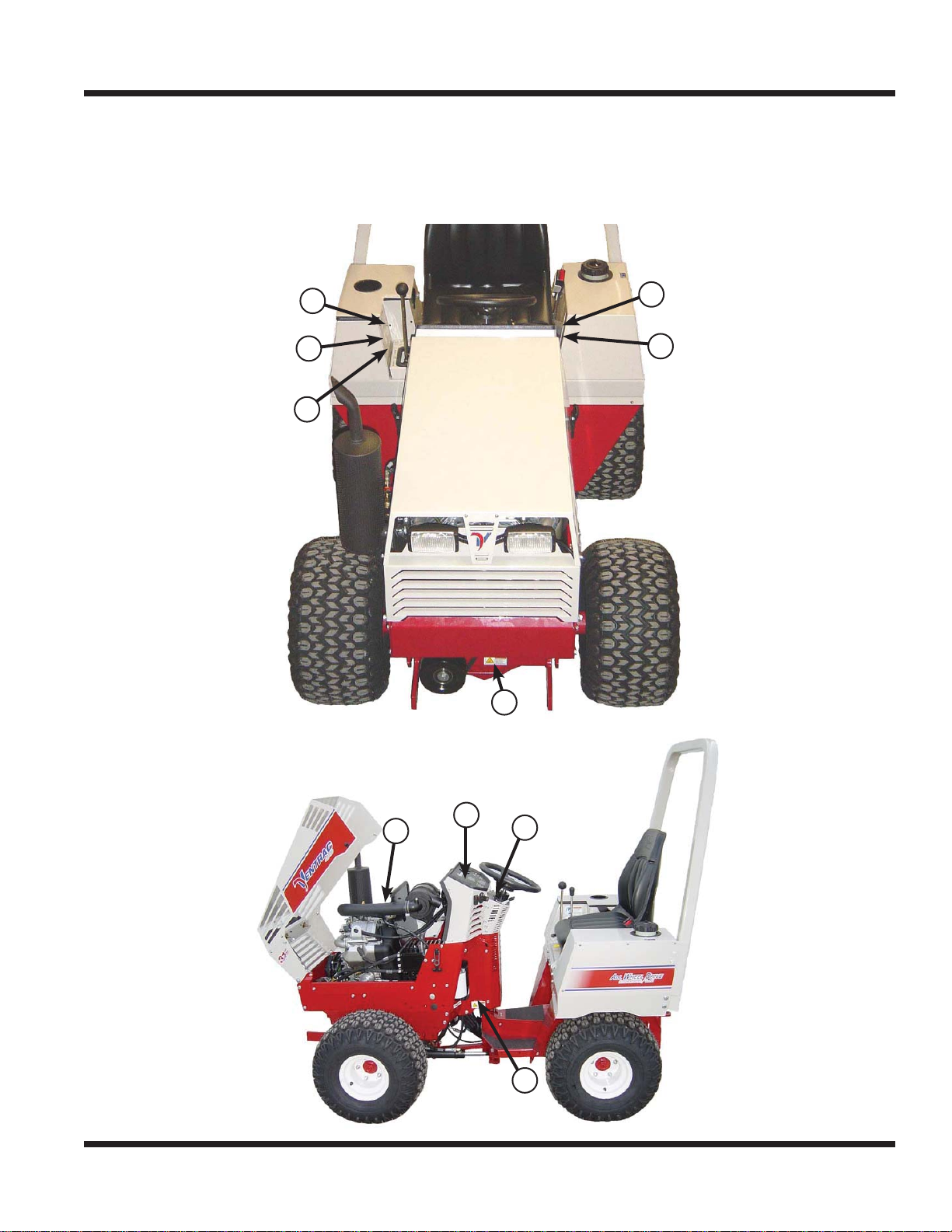
The following safety decals must be maintained on your Ventrac 4100 power unit.
Keep all safety decals legible. Remove all grease, dirt, and debris from safety decals and instructional
labels. If any decals are faded, illegible, or missing, contact your dealer promptly for replacements.
When new components are installed, be sure that current safety decals are affi xed to the replacement
components.
A
F
I
J
B
E
C
H
G
D
Safety - 9
Page 10
C
F
E
B
A
A
D
I
H
G
J
D
G
SAFETY
B
E
H
C
F
I
J
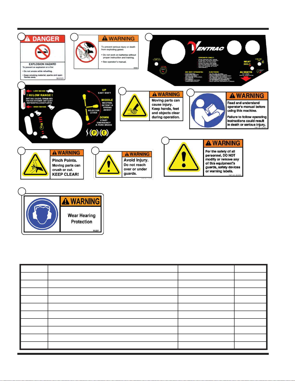
Decal Description Part Number Quantity
A Danger, Explosion Hazard 00.0121 1
B Warning - Battery Gases 00.0124 1
C Upper Dash - General Safety 00.0175 1
D Lower Dash - High/Low Shift Safety 00.0176 1
E Warning - Moving Parts 00.0216 1
F Warning - Read Owners Manual 00.0217 1
G Warning - Pinching Points 00.0218 2
H Warning - Avoid Injury 00.0219 1
I Warning - Safety Alteration 00.0220 1
J Warning - Hearing PPE 00.0291 1
Safety - 10
Page 11
SAFETY
General Safety Procedures
for Ventrac Power Units, Attachments, & Accessories
Training Required
• The owner of this machine is solely responsible for properly training the operators.
• The owner/operator is solely responsible for the operation of this
machine and prevention of accidents or injuries occurring to him/herself, other people, or property.
• Do not allow operation or service by children or untrained personnel.
Local regulations may restrict the age of the operator.
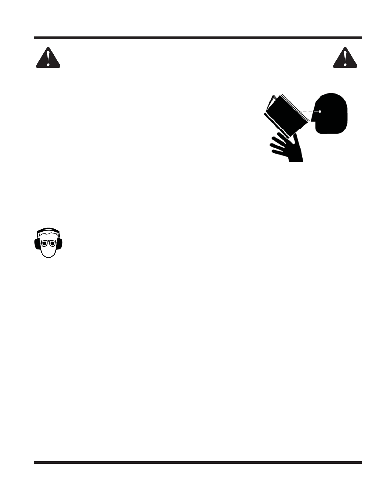
• Before operating this machine, read the operator’s manual and understand its contents.
• If the operator of the machine cannot understand this manual, then it
is the responsibility of this machine’s owner to fully explain the material
within this manual to the operator.
• Learn and understand the use of all controls.
• Know how to stop the power unit and all attachments quickly in the event of an emergency.
Personal Protective Equipment Requirements
It is the responsibility of the owner to be sure that the operators use the proper personal protective equipment while operating the machine. Required personal protective equipment includes, but is not limited to,
the following list.
• Wear a certifi ed ear protection device to prevent loss of hearing.
• Prevent eye injury by wearing safety glasses while operating the machine.
• Closed toe shoes must be worn at all times.
• Long pants must be worn at all times.
• When operating in dusty conditions, it is recommended that a dust mask be worn.
Operating Safely
• Inspect machine before operation. Repair or replace any damaged, worn, or missing parts. Be sure
guards and shields are in proper working condition and are secured in place. Make all necessary
adjustments before operating machine.
• Some pictures in this manual may show shields or covers opened or removed in order to clearly illustrate
any instructions. Under no circumstance should the machine be operated without these devices in place.
• Alterations or modifi cations to this machine can reduce safety and could cause damage to the machine.
Do not alter safety devices or operate with shields or covers removed.
• Before each use, verify that all controls function properly and inspect all safety devices. Do not operate
if controls or safety devices are not in proper working condition.
• Check parking brake function before operating. Repair or adjust parking brake if necessary.
• Observe and follow all safety decals.
• All controls are to be operated from the operator’s seat only.
• Always wear a seat belt if the machine has a roll cage/bar installed.
• Ensure the attachment or accessory is locked or fastened securely to the power unit before operating.
• Ensure that all bystanders are clear of the power unit and attachment before operating. Stop machine if
someone enters your work area.
• Always be alert to what is happening around you, but do not lose focus on the task you are performing.
Always look in the direction the machine is moving.
• Look behind and down before backing up to be sure of a clear path.
• If you hit an object, stop and inspect the machine. Make all necessary repairs before operating machine again.
• Stop operation immediately at any sign of equipment failure. An unusual noise can be a warning of equipment
failure or a sign that maintenance is required. Make all necessary repairs before operating machine again.
Safety - 11
Page 12
SAFETY
SAFETY
General Safety Procedures
for Ventrac Tractors, Attachments, & Accessories
Operating Safely (continued)
• If equipped with a high/low range feature, never shift between high and low range while on a slope.
Always move the machine to level ground and place the selector lever in park before shifting range.
• Do not leave machine unattended while it is running.
• Always park the machine on level ground.
• Always shut off engine when connecting attachment drive belt to the power unit.
• Never leave the operator’s seat without lowering the attachment to the ground, setting the parking
brake, shutting off the engine, and removing the ignition key. Make sure all moving parts have come to
a complete stop before dismounting.
• Never leave equipment unattended without lowering the attachment to the ground, setting the parking
brake, shutting off the engine, and removing the ignition key.
• Only operate in well-lit conditions.
• Do not operate when there is a risk of lightning.
• Never direct the discharge of any attachment in the direction of people, buildings, animals, vehicles, or
other objects of value.
• Never discharge material against a wall or obstruction. Material may ricochet back towards the operator.
• Use extra caution when approaching blind corners, shrubs, trees, or other objects that may obscure vision.
• Do not run the engine in a building without adequate ventilation.
• Do not touch the engine or the muffl er while the engine is running or immediately after stopping the engine.
These areas may be hot enough to cause a burn.
• Do not change the engine governor settings or over-speed the engine. Operating engine at excessive speed
may increase the hazard of personal injury.
• To reduce the hazard of fi re, keep the battery compartment, engine, and muffl er areas free of grass, leaves,
and excessive grease.
Preventing Accidents
• Clear working area of objects that might be hit or thrown from machine.
• Keep people and pets out of mowing area.
• Know the work area well before operation. Do not operate where traction or
stability is questionable.
• Reduce speed when you are operating over rough ground.
• Equipment can cause serious injury and/
or death when improperly used. Before
operating, know and understand the
operation and safety of the power unit
and the attachment being used.
• Do not operate machine if you are not in good physical and
mental health, if you will be distracted by personal devices, or are
under the infl uence of any substance which might impair deci-
sion, dexterity, or judgment.
• Children are attracted to machine activity. Be aware of children and
do not allow them in the working area. Turn off the machine if a
child enters the work area.
Keep Riders Off
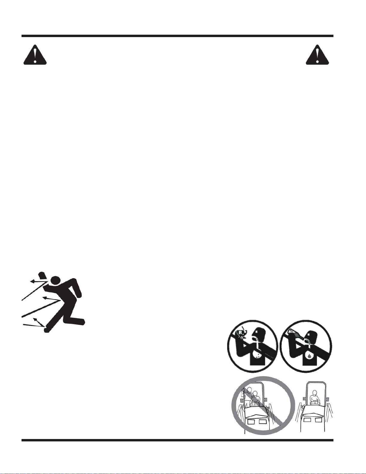
• Only allow the operator on the power unit. Keep riders off.
• Never allow riders on any attachment or accessory.
Safety - 12
Page 13
SAFETY
General Safety Procedures
for Ventrac Tractors, Attachments, & Accessories
Operating On Slopes
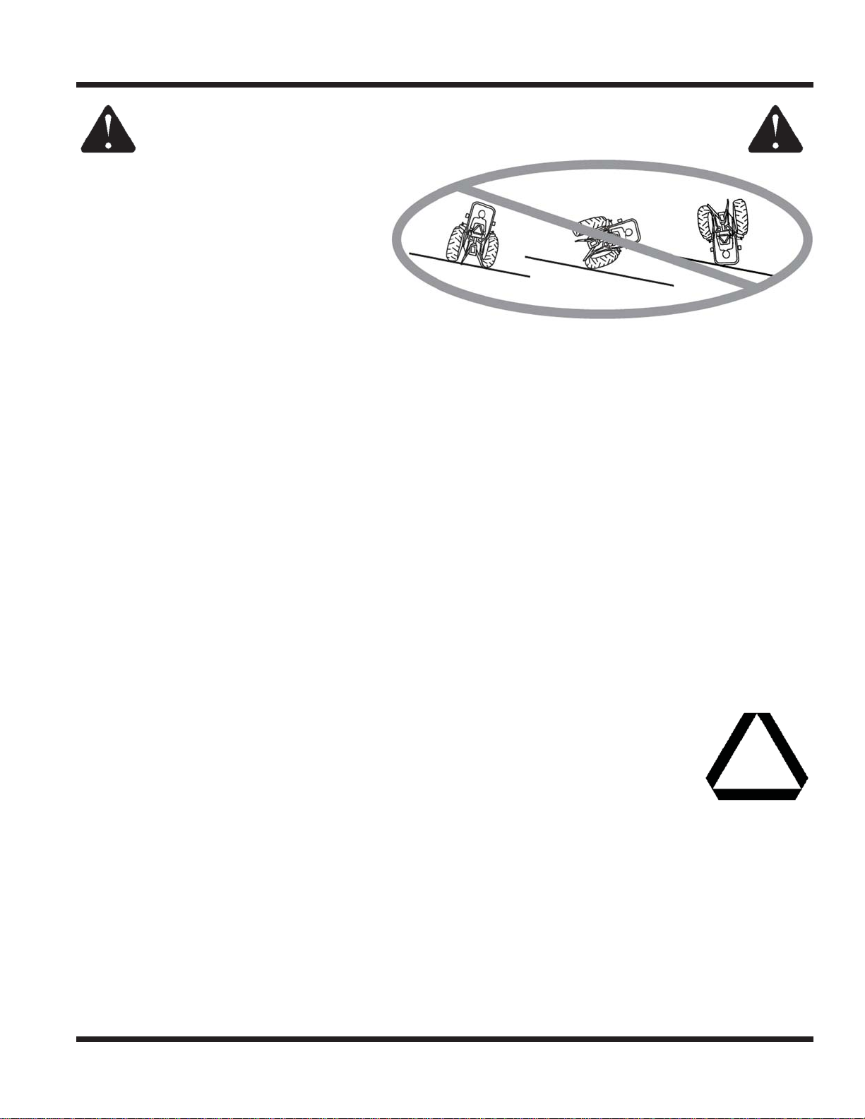
• Slopes can cause loss-of-control and
tip-over accidents, which can result in
severe injury or death. Be familiar with the
emergency parking brake, along with the
power unit controls and their functions.
• If power unit is equipped with a fold down
roll bar, it must be locked in the upright
position when operating on any slope.
• Use low range (if equipped) when operating
on slopes greater than 15 degrees.
• Do not stop or start suddenly when operating on slopes.
• Never shift between high and low range while on a slope. Always move the power unit to level ground
and engage the parking brake before shifting range or placing the power unit in neutral.
• Variables such as wet surface and loose ground will reduce the degree of safety. Do not drive where
machine could lose traction or tip over.
• Keep alert for hidden hazards in the terrain.
• Stay away from drop-offs, ditches, and embankments.
• Sharp turns should be avoided when operating on slopes.
• Pulling loads on hills decreases safety. It is the responsibility of the owner/operator to determine loads
that can safely be controlled on slopes.
• Transport machine with attachment lowered or close to the ground to improve stability.
• While operating on slopes, drive in an up and down direction when possible. If turning is necessary
while driving across slopes, reduce speed and turn slowly in the downhill direction.
• Assure a suffi cient supply of fuel for continuous operation. A minimum of one-half tank of fuel is recommended.
Roadway Safety
• Operate with safety lights when operating on or near roadways.
• Obey all state and local laws concerning operation on roadways.
• Slow down and be careful of traffi c when operating near or crossing roadways. Stop before crossing
roads or sidewalks. Use care when approaching areas or objects that may obscure vision.
• If there is doubt of safety conditions, discontinue machine operation until a time when
operation can be performed safely.
• When operating near or on roadways, have a Slow Moving Vehicle Emblem clearly
displayed.
Truck Or Trailer Transport
• Use care when loading or unloading machine into a truck or trailer.
• The parking brake is not suffi cient to lock the machine during transport. Always secure the power unit
and/or attachment to the transporting vehicle.
• Shut off fuel supply to power unit during transport on truck or trailer.
• If equipped, turn the battery disconnect switch to the Off position to shut off electrical power.
Safety - 13
Page 14

SAFETY
General Safety Procedures
for Ventrac Tractors, Attachments, & Accessories
Maintenance
• Keep all safety decals legible. Remove all grease dirt, and debris from safety decals and instructional labels.
• If any decals are faded, illegible, or missing, contact your dealer promptly for replacements.
• When new components are installed, be sure that current safety decals are affi xed to the replacement
components.
• If any component requires replacement, use only original Ventrac replacement parts.
• Always disconnect the negative battery cable from the battery when working with electrical components.
• Keep all bolts, nuts, screws, and other fasteners properly tightened.
• Always lower the attachment to the ground, engage parking brake, shut off engine, and remove the
ignition key. Make sure all moving parts have come to a complete stop before cleaning, inspection,
adjusting or repairing.
• If the power unit, attachment, or accessory requires repairs or adjustments not instructed in the operator’s
manual, the power unit, attachment, or accessory must be taken to an authorized Ventrac dealer for service.
• Never perform maintenance on the power unit and/or attachment if someone is sitting in the operator’s seat.
• Always use protective glasses when handling the battery.
• Check all fuel lines for tightness and wear on a regular basis. Tighten or repair them as needed.
• To reduce the hazard of fi re, keep the battery compartment, engine, and muffl er areas free of grass,
leaves, and excessive grease.
• Do not touch the engine or the muffl er while the engine is running or immediately after stopping the
engine. These areas may be hot enough to cause a burn.
• Do not change the engine governor settings or over-speed the engine. Operating engine at excessive
speed may increase the hazard of personal injury.
• Springs may contain stored energy. Use caution when disengaging or removing springs and/or spring
loaded components.
• An obstruction or blockage in a drive system or moving/rotating parts may cause a buildup of stored
energy. When the obstruction or blockage is removed, the drive system or moving/rotating parts may
move suddenly. Do not attempt to remove an obstruction or blockage with your hands. Keep hands,
feet, and clothing away from all power-driven parts.
• Dispose of all fl uids in accordance with local laws.
Fuel Safety
• Do not refuel machine while smoking or at a location near fl ames or sparks.
• Always refuel the machine outdoors.
• Do not store machine or fuel container indoors where fumes or fuel can reach an open
fl ame, spark, or pilot light.
• Only store fuel in an approved container. Keep out of reach of children.
• Never remove fuel cap or add fuel with the engine running. Allow engine to cool before refueling.
• Never remove fuel cap while on a slope. Only remove when parked on a level surface.
• Replace all fuel tank and container caps securely.
• Do not overfi ll fuel tank. Only fi ll to bottom of fuel neck, do not fi ll fuel neck full. Overfi lling of fuel tank
could result in engine fl ooding or fuel leakage from the tank.
• If fuel is spilled, do not attempt to start the engine. Move the power unit away from the fuel spill and
avoid creating any source of ignition until fuel vapors have dissipated.
• If the fuel tank must be drained, it should be drained outdoors into an approved container.
• Dispose of all fl uids in accordance with local laws.
• Check all fuel lines for tightness and wear on a regular basis. Tighten or repair them as needed.
• The fuel system is equipped with a shut-off valve. Shut off the fuel when transporting the machine to
and from the job, when parking the machine indoors, or when servicing the fuel system.
Safety - 14
Page 15
SAFETY
General Safety Procedures
for Ventrac Tractors, Attachments, & Accessories
Hydraulic Safety
• Make sure all hydraulic connections are tight and all hydraulic hoses and tubes are in good condition.
Repair any leaks and replace any damaged or deteriorated hoses or tubes before starting the machine.
• Hydraulic leaks can occur under high pressure. Hydraulic leaks require special care and attention.
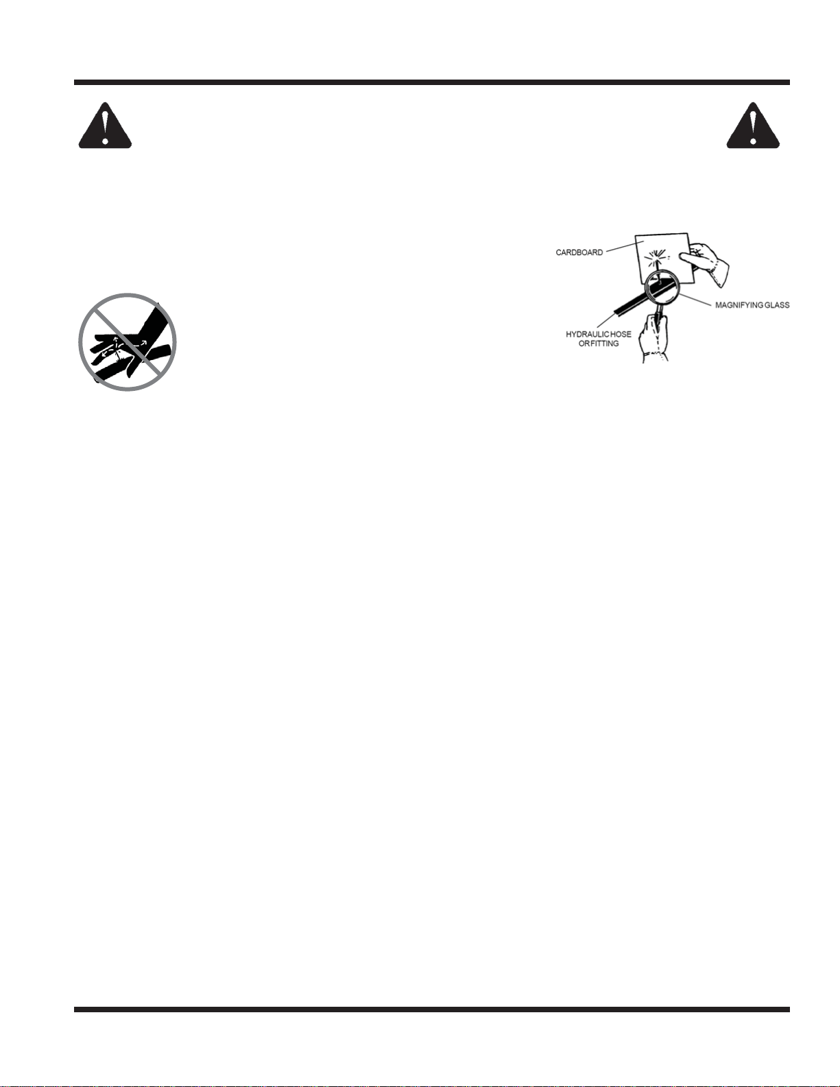
• Use a piece of cardboard and a magnifying glass to locate sus-
pected hydraulic leaks.
• Keep body and hands away from pinhole leaks
or nozzles that eject high pressure hydraulic
fl uid. Hydraulic fl uid escaping under high pres-
sure can penetrate the skin causing serious
injury. If hydraulic fl uid is injected into skin, seek
immediate medical attention.
• Hydraulic system may contain stored energy. Before performing maintenance or repairs on the hydraulic
system, remove attachments, engage parking brake, disengage weight transfer system (if equipped), shut
off engine, and remove ignition key. To relieve pressure on the auxiliary hydraulic system, shut off the power
unit engine and move the secondary S.D.L.A. lever left and right before disconnecting the auxiliary hydraulic
quick couplers.
• Dispose of all fl uids in accordance with local laws.
Safety - 15
Page 16
SAFETY
KT4100 Safety Procedures
• Weight transfer springs may contain stored energy. Always disengage the weight transfer system before
performing maintenance or repairs on the weight transfer system, the front hitch, or the lift hydraulics.
• Power unit hydraulic system may contain stored energy. Before performing maintenance or repairs on
the attachment hydraulic system, remove attachments, engage parking brake, disengage weight
transfer system, shut off engine, and remove ignition key.
The engine exhaust from this product contains
chemicals known to the State of California to cause
cancer, birth defects or other reproductive harm.
CALIFORNIA PROPOSITION 65
Battery Warning
Battery posts, terminals, and related accessories contain lead and lead
compounds, chemicals known to the State of California to cause cancer
and reproductive harm. Wash hands after handling!
Roll-Over Protective Structure
Your power unit is equipped with a Roll-Over Protective Structure (ROPS).
• Certifi ed seat belt anchor: #OSHA 1928.51.
• Certifi ed ROPS, roll bar: #OSHA 1928.52.
• Certifi ed ROPS, fold down roll bar: #OSHA 1928-51.
• Fold down ROPS must be fi xed in the upright position during operation.
• Always wear the seat belt during operation. Never jump from the power unit.
• During operation, the seat belt indicator light on the dash will turn on if the seat belt is not fastened.
The seat belt indicator light will turn off if the seat belt is fastened.
• If damaged, the roll bar or seat belt must be replaced before operation.
Alterations or modifi cations to this machine can
reduce safety and could cause damage to the
machine. Do not alter safety devices or operate
with shields or covers removed.
Safety - 16
Page 17

SAFETY
KT4100 Safety Procedures
Operator Interlock Systems
The operator interlock systems:
• prevent the engine from starting unless the selector lever is in the park position.
• prevent the PTO clutch from engaging unless the operator is present on the seat and activates the PTO.
• Deactivates the PTO if the operator leaves the seat.
• prevents the power unit from moving unless the parking brake is released and the operator is pres-
ent on the seat.
Park the power unit on a level surface. Lower attachment to the ground and turn off power unit engine.
Chock tires to prevent rolling. Ensure the operating area is free of obstacles and bystanders.
Perform the following tests:
• The Ignition Circuit
• Sit on the seat.
• Place the power unit’s selector lever in the park position. Turn key to ‘start’. Starter should engage.
• Place the power unit’s selector lever in the neutral assist position. Turn key to ‘start’. Starter should
NOT engage.
• The PTO Circuit - Operator Presence
• Sit on the seat.
• Turn the ignition key to the ‘run’ position. (Do not start the engine for this test.)
• Press top portion of the PTO switch to activate the PTO. The PTO clutch should audibly engage.
• Rise off the seat. The PTO clutch should audibly disengage.
• Return to the seat with the PTO switch still activated. The PTO clutch should NOT engage.
• Turn the key to the ‘off’ position.
• Press the bottom portion of the PTO switch to turn the switch off.
• The PTO Circuit - Operator Interlock
• Sit on the seat.
• With the key in the off position, press the top portion of the PTO switch to activate the PTO. The PTO
clutch should NOT engage.
• With the PTO switch still in the on position, turn the key switch to the on position. The PTO clutch
should NOT engage.
• Press the bottom portion of the PTO switch to turn the switch off.
• Press top portion of the PTO switch to activate the PTO. The PTO clutch should audibly engage.
• S.D.L.A. Control Lever - Operator Presence
• Sit on the seat.
• Place the power unit’s selector lever in the easy shift position.
• Rise off the seat and simulate forward/reverse motion by attempting to move the S.D.L.A. control
lever forward and rearward. S.D.L.A. control lever should NOT move forward and rearward.
Place the power unit’s selector lever in the park position and remove the wheel chocks.
• S.D.L.A. Control Lever - Parking Brake
• Sit on the seat.
• Start the power unit engine.
• With the selector lever still in the park position, move the S.D.L.A. control lever forward and rearward.
The S.D.L.A. control lever should move forward and rearward, but the power unit should NOT move.
• Place the power unit’s selector lever in the neu-
tral assist position.
• Slowly move the S.D.L.A. control lever forward
and rearward. The power unit should drive according to the input of the S.D.L.A. control lever.
If any test fails, do not operate. Repair before operating.
Alterations or modifi cations to this machine can
reduce safety and could cause damage to the
machine. Do not alter safety devices or operate
with shields or covers removed.
Safety - 17
Page 18
OPERATIONAL CONTROLS
CC
BB
AA
V
T
W
U
S
Under Seat
Q
P
R
A
B
D
E
F
G
H
IIJ
C
K
L
R
O
N
M
X
Y
Z
OPERATIONAL CONTROLS
E
G
F
P
Q
H
R
D
J
A
B
C
K
M
L
V
T
U
O
R
S
N
BB
Y
X
W
Z
CC
Under Seat
Operation - 18
AA
Page 19
OPERATIONAL CONTROLS
OPERATIONAL CONTROL LOCATIONS
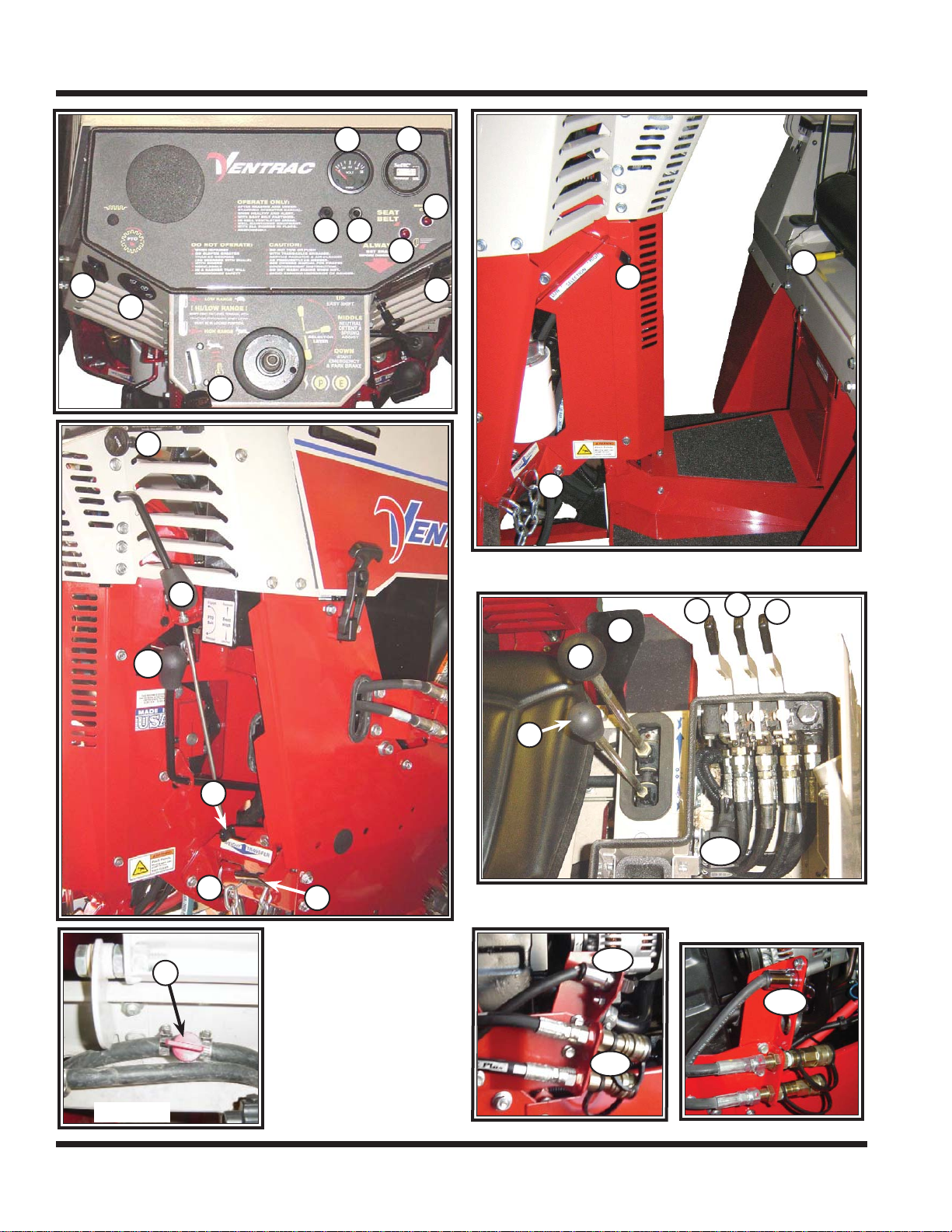
The images on the previous page match with reference letters as shown below to help identify the
locations of operational controls for this power unit.
A - PTO Switch
B - Ignition Key Switch
C - Throttle
D - Volt Gauge
E - Tachometer/Hour Meter
F - Engine Oil Pressure Warning Light
G - Seat Belt Light
H - Light Switch
I - 12 Volt Switch (On/Off)*
J- 12 V olt Switch (Momentary On/Off/On)*
K - Choke
L - Selector Lever/Parking Brake
M - Belt Tension Lever
N - Front Hitch Latch Lever
O - Front Hitch Lock
P - Seat Slide Adjustment Lever
Q - High/Low Range Shift Handle
R - Weight Transfer*
S - Fuel Shut-off Valve
T - Primary S.D.L.A. Control
U - Secondary S.D.L.A. Control
V - Foot Pedal*
W - 12 Volt Rear Outlet & 4-Pin Socket*
X - 3pt Hitch Control Handle*
Y - Left Rear Auxiliary Hydraulics Handle*
Z - Right Rear Auxiliary Hydraulics Handle*
AA - Auxiliary Hydraulic Quick Couplers
BB - 12 Volt 4-Pin Socket*
CC - Electric PTO Remote (5-Pin Socket)*
DD - Seat Latch (See page 18)
EE - Seat Prop (See page 18)
FF - Seat Lock Lever* (See page 18)
* Optional Equipment
POWER TAKE OFF (PTO) SWITCH (A)
Depressing the top of the PTO switch engages the
electric clutch to provide power to the front attachment. Depressing the bottom part of the switch will
disengage the clutch and apply the clutch brake to
stop the attachment. Note: The PTO will shut off
automatically if the operator leaves the power unit
seat. To restart, fi rst return to the seat, then disen-
gage and re-engage the PTO switch.
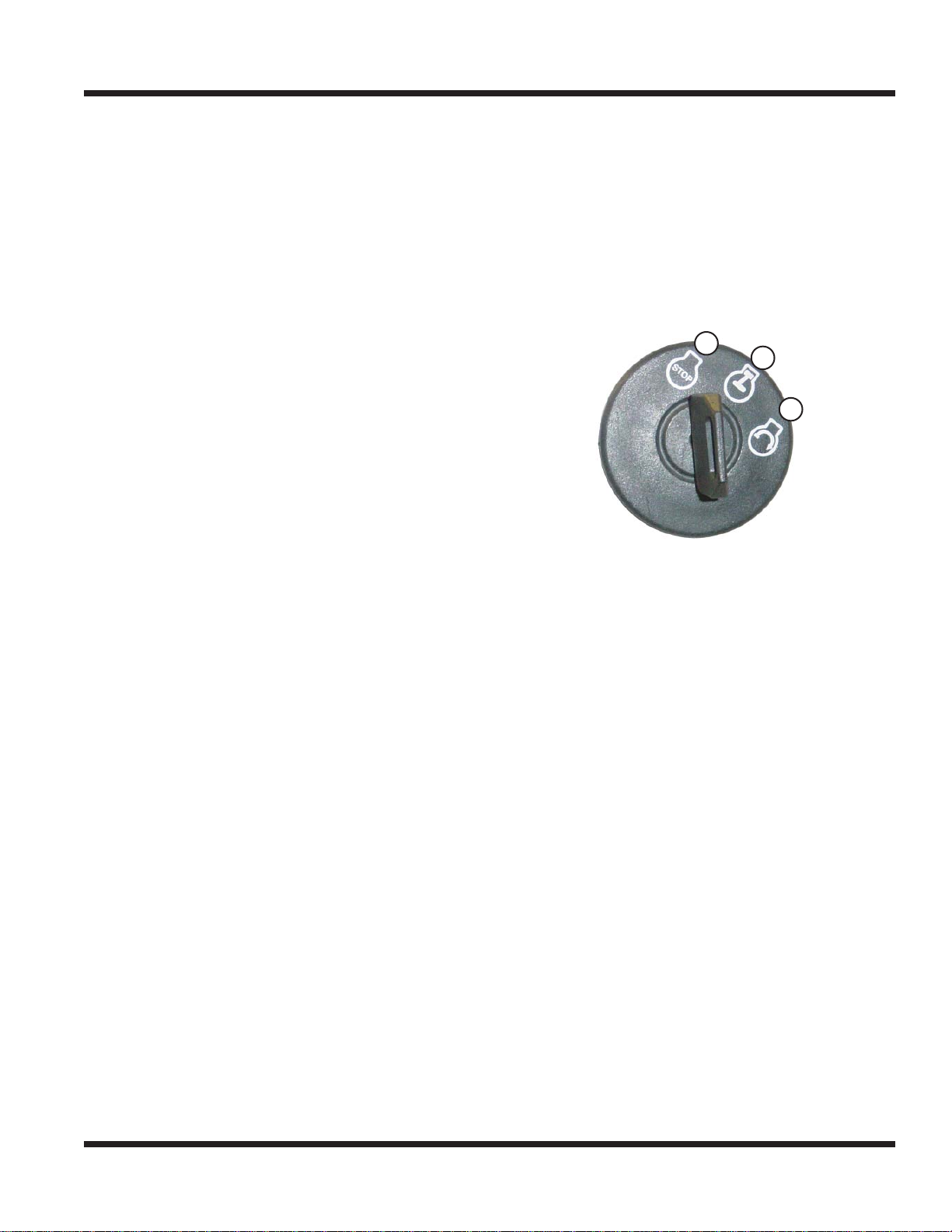
IGNITION KEY SWITCH (B)
1
2
3
1. Off or Stop Position - All 12 volt power going
through the key switch is off.
2. On or Run Position - Engine run position.
3. Start - When key is turned to the start position,
starter will engage.
THROTTLE (C)
Moving the lever forward increases the engine
Revolutions Per Minute (RPM). Moving it back slows
the engine to an idle.
VOLT GAUGE (D)
Displays the voltage level of the charging system.
TACHOMETER & HOUR METER (E)
When the engine is running, the engine RPM is displayed. When the engine is not running, the engine
run time in hours is displayed.
ENGINE OIL PRESSURE WARNING LIGHT (F)
Signifi es low or no engine oil pressure.
SEAT BELT LIGHT (G)
Light indicates when seat belt is not in use. When
seat belt is fastened, the light will turn off.
Operation - 19
Page 20
OPERATIONAL CONTROLS
1
2
3
LIGHT SWITCH (H)
Depressing the top of the switch will turn on the
headlights, the taillights, and the backlighting on the
dash gauge(s). Depressing the bottom part of the
switch will turn the lights off. Lights only work when
the key is in the run or start position.
12 VOLT SWITCHES (I & J)
Optional accessory. These switches turn off and on
the 12 volt accessories utilized by some attachments.
CHOKE (K)
Pulling the choke handle out aids in starting a cold
engine.
SELECTOR LEVER/PARKING BRAKE (L)
Position #1: Park/Start Position. In this position, the
park brake is applied, and the
3
S.D.L.A. control lever is
locked out. The lever must be
in this position to start.
Position #2: Neutral Assist
Position. In this position, the
2
position makes neutral easy to select and maintain. Neutral assist is recommended when learning
the operation of your Ventrac, loading & unloading,
attaching and removing attachments, and whenever
the operator is working in tight areas or is unsure of
the power unit’s response to the task being performed.
Position #3: Easy shift position. In this position, the
S.D.L.A. control lever is in an “easy shift” mode. This
position is designed for experienced operators for
operation of the power unit in open areas where
travel speed and direction are relatively constant
and control is easily maintained. Easy shift reduces
operator arm fatigue when using the power unit for
prolonged periods of time.
Stopping in this position requires the operator to
return the S.D.L.A. control or foot pedal to the
neutral position.
parking brake and the S.D.L.A.
control lever are released. If
an operator is present on the
seat, the power unit can now
be operated. In the neutral
assist position, the S.D.L.A.
1
control lever has a “spring
assist to neutral” action. This
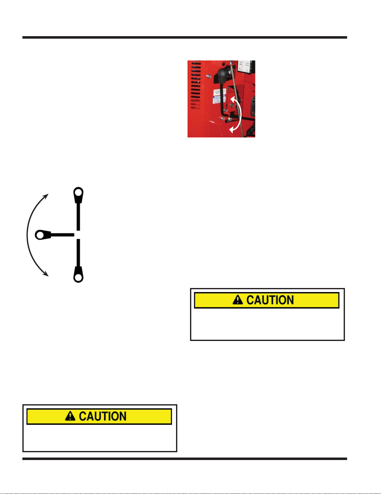
BELT TENSION LEVER (M)
Rotating the belt tension
lever up until it locks applies
tension to the attachment
drive belt. Rotating the belt
tension lever down releases
the tension of the attachment drive belt, allowing the
operator to remove or install
the attachment drive belt.
FRONT HITCH LATCH LEVER (N)
The front hitch latch handle engages or disengages
the hitch latch for attaching or detaching Ventrac attachments. Raise the handle to open the hitch latch.
Lower the handle and ensure the handle is secured
in the notch to close the hitch latch.
FRONT HITCH LOCK (O)
The front hitch lock prevents the accidental release
of the front hitch latch lever. To release, lift the tab
of the front hitch lock and raise the front hitch latch
handle.
SEAT SLIDE ADJUSTMENT LEVER (P)
Move lever outward to release lock. Slide the seat to
desired location and release lever.
HIGH/LOW RANGE SHIFT HANDLE (Q)
Never shift while under load, while moving, or
while on a slope. Always ensure the shift handle
is secured in the lock position at the end of each
shift stroke.
The high/low range shift handle shifts both the front
and rear transaxles simultaneously. With the power
unit parked on level ground, push the shift handle
forward to select low range. Pull the shift handle
back to select high range. Ensure the shift handle is
secured in the lock position at the end of each shift
stroke.
WEIGHT TRANSFER (R)
Optional Accessory. The weight transfer system
allows the operator to select the amount of weight
transferred from the front mounted attachment to
the front drive wheels of the power unit. Transferring weight from the attachment to the power unit
Operation - 20
Page 21

OPERATIONAL CONTROLS
improves traction & hillside stability, aids in lifting,
reduces steering effort, and lessens the attachment
resistance when in contact with the ground. Note:
The weight transfer system is only active while the
primary S.D.L.A. is in the fl oat position.
The weight transfer chains determine the amount
of weight being transferred from the attachment to
the front wheels of the power unit. If no chain links
are outside the weight transfer plate, no weight will
be transferred from the attachment. The more chain
links outside the weight transfer plate, the more
weight will be transferred from the attachment.
FUEL SHUT-OFF VALVE (S)
The fuel shut-off valve controls the fl ow of fuel to the
power unit engine. It can be turned off to prevent
fuel leakage when changing fuel fi lters or servicing
fuel system.
S.D.L.A. LEVER (T & U)
(Speed, Direction, Lift, and Auxiliary Control Levers)
The S.D.L.A. is the primary control for the power
unit and consists of two parts: The primary lever (T)
controls the Speed, Direction of power unit & Lift of
the hitch arms. The secondary lever (U) controls the
Auxiliary hydraulic circuit.
S – Speed: The amount of forward or backward
movement of this lever controls the ground speed of
the power unit.
D - Direction: The forward or backward movement of
the lever controls the direction of the power unit.
L – Lift: The lift function of the lever has four posi-
tions: Up, Hold, Down, and Float Lock. “Hold” is the
default position; this holds the lift arms from moving
up or down. Pulling the lever to the left raises the
hitch arms. Pushing the lever to the right lowers the
hitch arms. Float position is attained by pushing the
lever to the right until the fl oat detent locks the lever
in place.
A - Auxiliary: The left or right movement of the sec-
ondary lever controls the functions of attachments
that require the auxiliary hydraulic circuit. An optional fl oat kit (part # 23.0111-7) is available for the
auxiliary circuit.
12 VOLT REAR OUTLET & 4-PIN SOCKET (W)
Optional accessory. The outlet provides 12 volts of
electrical power for a variety of products such as
cell phones, radios, spot lights, air compressors,
and more. The socket provides electrical power to
rear mounted attachments equipped with electrical
controls. (e.g. Spreader.)
3 POINT HITCH & REAR AUXILIARY CONTROL
H
ANDLES (X, Y, & Z)
Optional accessory. The left control handle (X)
raises or lowers the 3 point hitch arms. The middle
control handle (Y) controls the left rear set of hydraulic quick couplers. The right control handle (Z)
controls the right rear set of quick couplers.
AUXILIARY HYDRAULIC QUICK COUPLERS (AA)
The two couplers are a part of the auxiliary hydraulic circuit and are used with an attachment which
requires hydraulics (e.g. to angle a dozer blade or
rotate the discharge on the snow blower).
12 VOLT 4-PIN SOCKET (BB)
Optional accessory. The socket is controlled by the
12 volt switches and provides electrical power to
attachments equipped with electrical controls. (e.g.
broom rotation actuator, snowblower discharge
chute angle, etc.)
ELECTRIC PTO REMOTE (5-PIN SOCKET) (CC)
Optional accessory. The 5-pin socket is used with attachments equipped with a remote PTO switch, such
as the generator, allowing the operator to shut off
the power unit PTO from the attachment.
FOOT PEDAL (V)
Optional accessory. The foot pedal works in conjunction with the S.D.L.A. lever and can be used to control direction and speed when the operator’s hand is
removed from the S.D.L.A. lever.
Operation - 21
Page 22
OPERATIONAL CONTROLS
A
B
Seat Lock
Lever
(Disengaged)
Seat Lock
Lever
(Engaged)
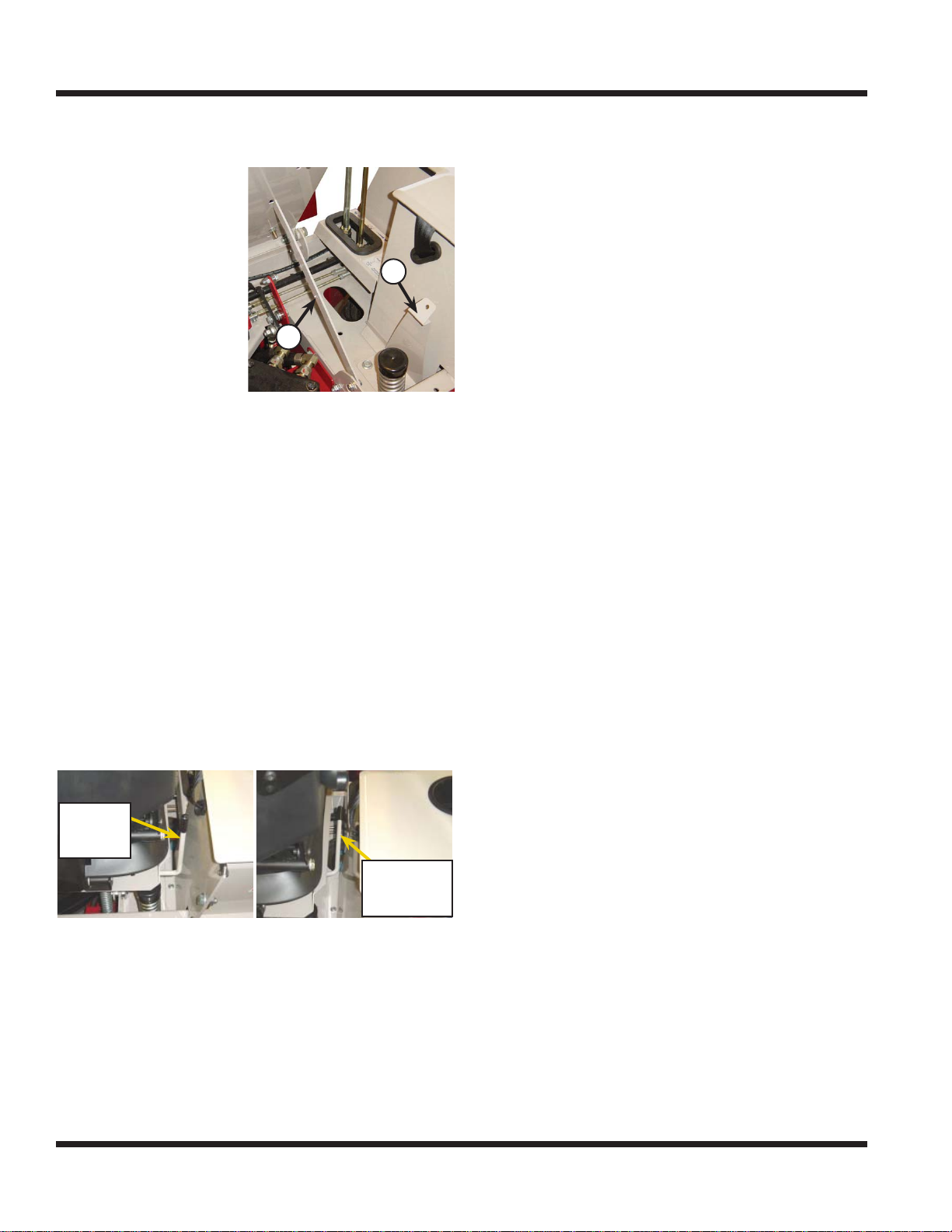
SEAT LATCH (DD)
The seat latch (A) secures the standard seat during
transport.
To release, pull the
latch away from the
seat plate while lifting
up on the seat.
A
SEAT PROP (EE)
The seat prop (B)
secures the seat in the
tipped forward position
while service is performed under the seat.
To secure, tip the seat
forward, lift up the seat prop, and insert the end into
the wide portion of the seat plate slot. Move the seat
prop to the narrow portion of the slot to prevent accidental release.
To release, move the seat prop to the wide portion of
the slot. Tip the seat forward while guiding the seat
prop out of the slot. Lower the seat prop back into
the seat box.
B
SEAT LOCK LEVER (FF)
The seat lock lever is included with the optional
suspension seat kit. It secures the suspension seat
during transport. It can also replace the standard
seat latch.
Engage the seat lock lever by lifting up until it locks
in the upright position. Disengage the seat lock lever
by pushing it down alongside the seat.
Seat Lock
Lever
(Engaged)
Seat Lock
Lever
(Disengaged)
The seat lock lever must be disengaged prior to
operation.
Operation - 22
Page 23
GENERAL OPERATION
FORWARD
REVERSE
NEUTRAL
GENERAL OPERATION
DAILY INSPECTION
Always set the parking brake, shut off the power
unit engine, remove the ignition key, and ensure
all moving parts have stopped before checking
mower deck or blade condition, or attempting
any repair or adjustment.
1.
Park the power unit on a level surface, with the
engine shut off and all fl uids cold.
2. Perform a visual inspection of the power unit.
Look for loose or missing hardware, damaged
components, or signs of wear. Inspect hydraulic
hoses, hydraulic fi ttings, and fuel lines to ensure
tight, leak free connections. Check belts for damage or excessive wear.
3. Check the power unit’s engine oil, hydraulic oil,
cooling system, tire pressure, and fuel level. Add
fl uid or service system as required.
4. Test the operator safety interlock system.
STARTING THE ENGINE
The 4100 is equipped with an interlock system for
your safety. The following procedure is to be followed to start the power unit:
1. The interlock system requires the “Selector Lever” to be in the park position, the S.D.L.A. lever
to be in the neutral position, and the PTO switch
to be turned off.
2. Move the throttle forward approximately ¼ of its
travel.
3. Pull out choke handle to the on position. Choke
may not be required when the engine is at operating temperature.
4. Turn the key to the start position and hold to
engage starter. Release key when engine starts.
Note: If engine fails to start, refer to troubleshooting section.
5. The engine and hydraulic oil must be warmed to
operating temperature before operations. Allow
the unit to run at approximately 1800 rpm until
the hydraulic fi lter is warm to touch.
The hydraulic fi lter is located just above the left
weight transfer control chain.
FORWARD AND REVERSE
Verify that the intended path is safe and free from
obstacles. When safe to move, begin by moving the
selector lever into either the neutral assist position
or the easy shift position.
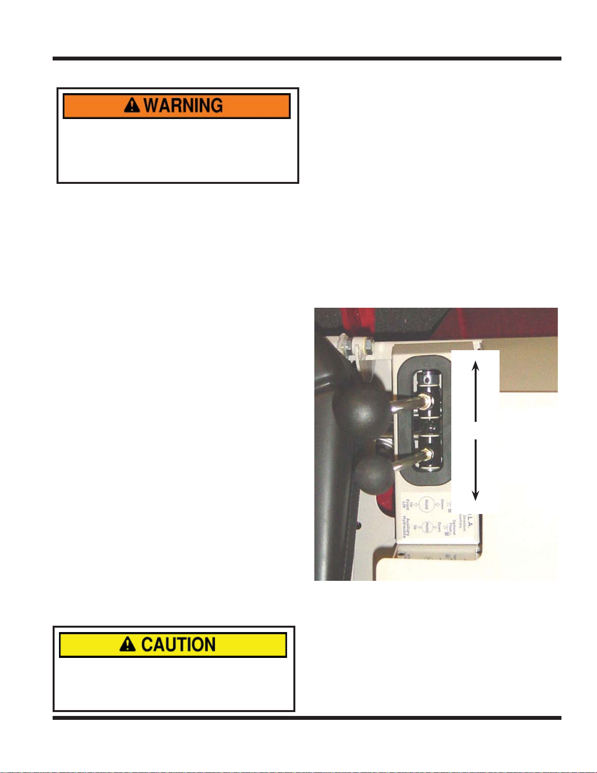
Power unit movement is controlled by moving the
S.D.L.A. control lever in the desired direction of travel.
Push the S.D.L.A. control lever forward to move
power unit in the forward direction. Pull the S.D.L.A.
control lever backward to make the power unit move
in the reverse direction. Changing the amount the
S.D.L.A. control lever is moved instantly changes the
ground speed of the power unit. Moving it one half of
the stroke will result in approximately one half of the
maximum ground speed. Moving it to the end of the
stroke will result in maximum ground speed.
FORWARD
NEUTRAL
REVERSE
Allow time for the hydraulic oil to circulate before the
power unit is operated. Severe damage could result
to the hydraulic system if adequate warm up isn’t allowed. Warm up time is increased in colder weather.
Operation - 23
Page 24
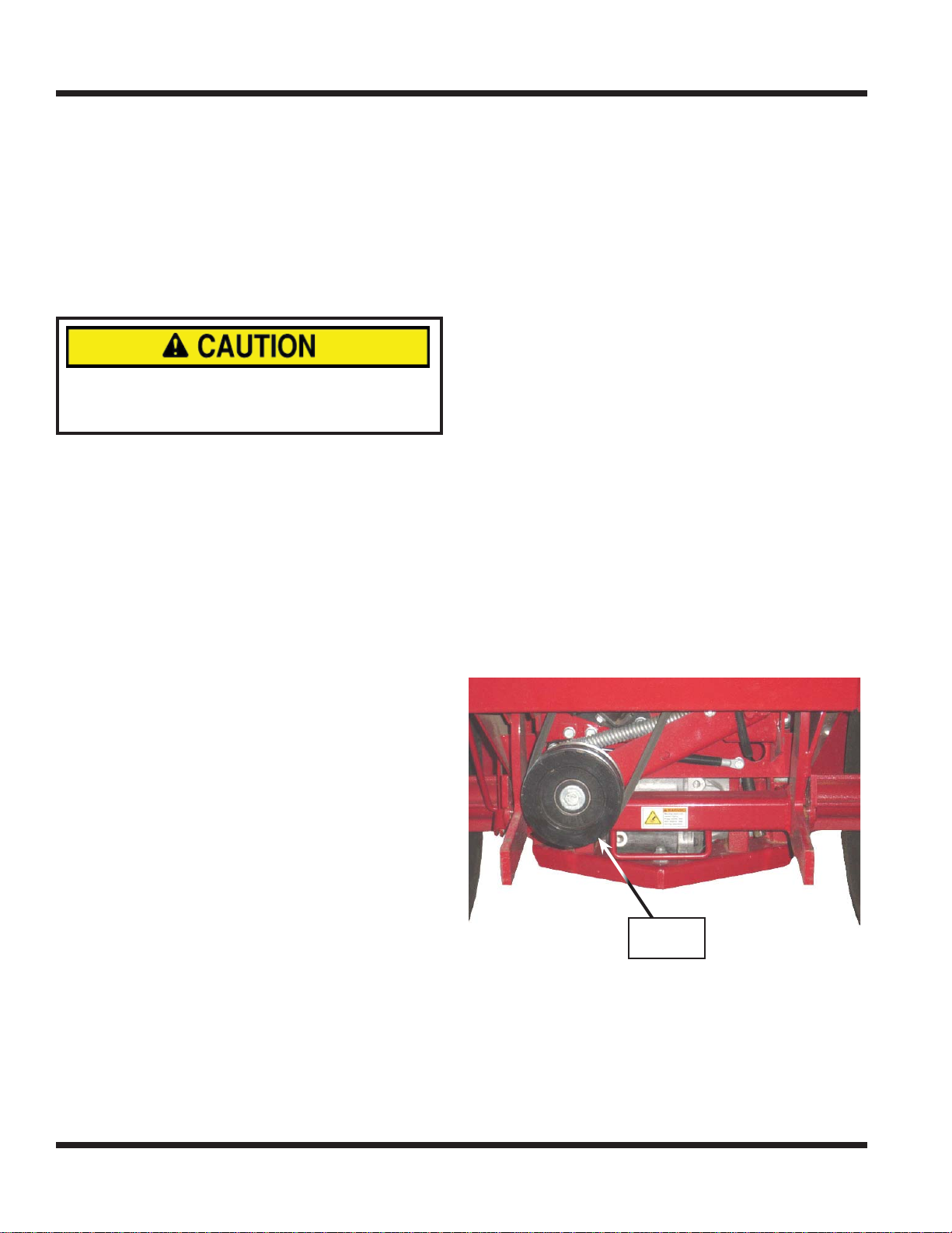
GENERAL OPERATION
PTO Drive
Pulley
GENERAL OPERATION
STOPPING THE POWER UNIT
To slow or stop the power unit, move the S.D.L.A.
control lever in the opposite direction that you are
traveling. Return the S.D.L.A. control lever to the
neutral position to make a complete stop. A foot pedal
brake is not required because you use the S.D.L.A.
control lever to stop the power unit. If in the case of
an emergency and the power unit cannot be stopped
with the S.D.L.A. control lever, move the selector
lever to the park position to stop the power unit.
If the selector lever is placed in the park position
in the case of an emergency, the power unit will
come to an abrupt stop.
ATTACHING
1. Drive the power unit slowly forward into the hitch
arms on the attachment. Align the lift arms of
the power unit with the attachment hitch arms
by raising or lowering the front hitch to complete
the engagement.
2. Once completely engaged, move the front hitch
latch lever to the closed position.
3. Engage the parking brake and shut off the
engine.
4. Place the attachment belt over the front groove
of the PTO drive pulley on the power unit. Ensure the belt is properly seated in each pulley.*
5. Engage the PTO belt tension lever.*
6. Clean the quick couplers and connect to the
auxiliary hydraulics.*
7. Connect the electric plug to the matching socket
on the power unit.*
*Applies only if attachment is equipped.
7. Move the secondary S.D.L.A. lever left and right
to release pressure from the auxiliary hydraulic
circuit and disconnect the hydraulic quick couplers from the power unit.*
8. Disconnect the electric plug from the socket on
the power unit.*
9. Disengage the front hitch latch lever.
10. Restart power unit and slowly back away from
the attachment.
*Applies only if attachment is equipped.
OPERATING ATTACHMENTS
Refer to the attachment’s manual for the proper
operation and use of the particular attachment that
is being operated.
FRONT HITCH
The front hitch is used to secure attachments to
power unit, and to raise and lower the attachment.
The front hitch is controlled by the primary S.D.L.A.
lever. Pull the lever to the left to raise the attachment, push the S.D.L.A. lever to the right to lower
the attachment. The primary S.D.L.A. is equipped
with a ‘fl oat’ position. Push the S.D.L.A. lever to the
far right position until the fl oat detent engages and
stays in place to operate in fl oat.
PTO DRIVE BELT & PULLEY
DETACHING
1. Park the power unit on a level surface and move
the selector lever to the park position.
2. Fully raise attachment and set weight transfer to
the off position.
3. Lower the attachment to the ground and place
the primary S.D.L.A. lever in the fl oat position.
4. Shut off engine.
5. Disengage the PTO belt tension lever.*
6. Remove the attachment belt from the PTO drive
pulley of the power unit.*
Operation - 24
PTO Drive
Pulley
If the attachment requires a drive belt, release the
belt tension lever and install the attachment belt
around the drive pulley at the location shown above.
When the belt is in place around the drive pulley,
rotate the belt tension lever up to tighten the belt.
Engage the PTO by depressing the top of the PTO
switch. Note: PTO will engage only if operator is
present on the seat.
Page 25
GENERAL OPERATION
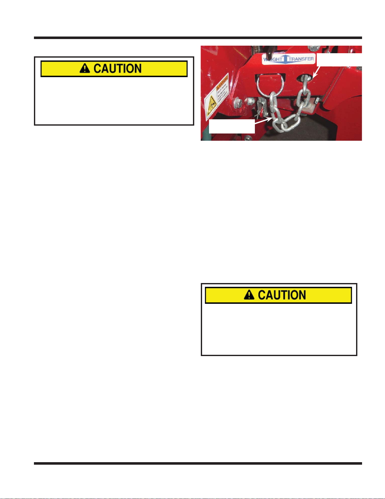
Weight Transfer
Chain
Weight Transfer
Chain Lock
GENERAL OPERATION
FRONT AUXILIARY COUPLERS
EQUIPMENT DAMAGE!
Dirt and other debris in hydraulic system can
cause damage to the system. Wipe clean the
mating parts of the couplers before coupling.
Use protective rubber plugs over hydraulic
couplers when not in use.
If attachment requires auxiliary hydraulics, couple the
attachment hoses with the front auxiliary couplers. This
is done by sliding the collar of the coupler rearward
and inserting the end of the attachment hose into the
coupler and releasing the collar. If the collar will not
snap forward on its own, pull it forward manually.
The couplers that the hoses are attached to will
affect which way the secondary S.D.L.A. lever is
pushed to control the action of the attachment. If
the hoses are connected and the action is not the
desired motion, then switch the hoses the couplers
are attached to. Auxiliary couplers are controlled by
moving the secondary S.D.L.A. lever left or right.
NOTE: Pressure build-up in the attachment hose
and on the power unit couplers may occur, causing
diffi cult installation of hoses. If hoses do not easily
connect, try one or both of the following steps: 1)
To release the pressure from power unit couplers,
turn off engine and move the secondary lever of
the S.D.L.A. right and left to release pressure in the
power unit’s hydraulic circuit.
2) To release pressure in the attachment hose,
loosen one of the hose ends, tighten when pressure
is released.
WEIGHT TRANSFER (OPTIONAL ACCESSORY)
The weight transfer system transfers weight from the
attachment to the front wheels of the power unit. The
operator can select different transfer rates by adjusting the right and left weight transfer chains.
To set the weight transfer, raise the front hitch to its
maximum height.
Weight Transfer
Chain Lock
Weight Transfer
Chain
Lift the weight transfer chain link out of the chain
lock slot. Feed the chain back through the hole to
decrease amount of transferred weight or pull the
chain out through the hole to increase the amount
of transferred weight. When the desired setting is
reached, insert chain link back in the chain lock slot.
Selecting the proper amount of weight to transfer
depends on attachments, ground conditions and
operator preference. A lightweight attachment (e.g.
KA160 Power Blower) will not go down with full
weight transfer on. With full weight transfer on and
mowing in the fl oat position, the mower may not
come down quickly enough when going through
uneven terrain. Weight transfer must be reduced or
speed must be lowered.
HIGH/LOW RANGE
Never shift while under load, while moving, or
while on a slope. Always ensure the shift handle
is secured in the lock position at the end of each
shift stroke.
For slopes greater than 15 degrees, always
use low range.
Low range is recommended for most pulling, pushing, and slow travel. High range is ideal for transport
and light duty tasks.
Stop the power unit and engage the parking brake.
Move the shift lever to the desired range setting.
Occasionally engagement of the transaxle gears is
prevented by gear misalignment. Moving the steering wheel slightly to the right or left will move the
gears enough to complete the engagement.
Operation - 25
Page 26
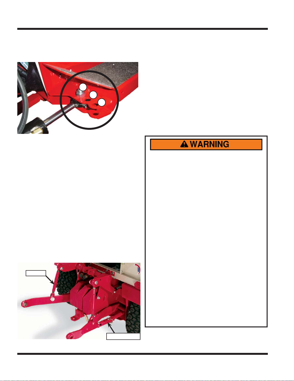
GENERAL OPERATION
1
2
3
Stabilizing Link
GENERAL OPERATION
TURNING RADIUS
Your power unit has three mounting positions for
the steering cylinder that determine the power unit’s
turning radius.
1
2
3
Position #1: Standard position. This position is the standard position, and enables the tightest turning radius.
#
Position
der must be installed in this position when operating
with dual wheels. The resulting turning radius will be
larger than in position
Position
steering cylinder must be installed in this position
when the cab is installed or when operating the
Versa-loader. The resulting turning radius will be
larger than in position
2: Dual wheel position. The steering cylin-
#
1.
#
3: Cab and Versa-loader position. The
#
2.
3 POINT HITCH (OPTIONAL ACCESSORY)
Some light and medium duty implements (non-PTO
powered) can be used on the rear of a 3 point hitch
equipped power unit.
The 3 point hitch is equipped with adjustable lift links
to control the individual draw bars. The stabilizing
links can be allowed to swing freely or can be locked
at a desired position.
Lift Link
handles. The inside handle raises and lowers the
draw bar. The middle handle controls the left rear set
of hydraulic quick couplers. The outside handle controls the right rear set of hydraulic quick couplers.
12 VOLT AUXILIARY OUTLETS (OPTIONAL
A
CCESSORY)
Certain attachments require a 12 volt auxiliary outlet. Plug the attachment’s 12 volt power cord into the
12 volt 4-pin plug located above the front auxiliary
quick couplers. Two switches are used to control
the actions of the 12 volt kit. A momentary on/off/on
is used for controlling movement that is only used
for a brief time. The on/off switch is used to activate
equipment or select different functions.
OPERATING ON SLOPES
AVOID PERSONAL INJURY!
Operation on slopes decreases power unit stability and increases the potential for unexpected
diffi culties. Only experienced operators should
operate the power unit on slopes and extra caution should be exercised.
• Use low range when operating on slopes
greater than 15 degrees.
• Never shift between high and low range while
on a slope. Always move the machine to level
ground and place the selector lever in park
before shifting range.
• Avoid uneven, loose, or wet terrain.
• Stay clear of drop-offs, holes, ditches, rocks,
or objects that could cause a sudden and/or
unexpected force on the power unit.
• Make slow and cautious starts, stops, and turns.
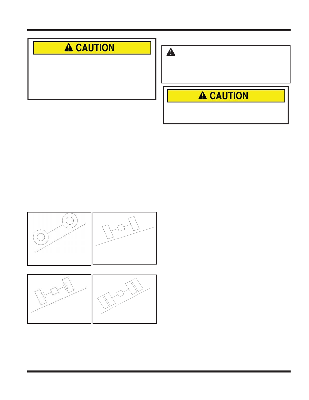
• Do not exceed the maximum degree of
operation. Refer to illustrations.
• Turn downhill when possible and/or reduce
the degree of turns.
• Assure a suffi cient supply of fuel for continu-
ous operation. A minimum of one-half tank of
fuel is recommended.
• To prevent fuel spillage, do not remove the
fuel tank cap while power unit is on a slope.
• Failure to follow items listed or to use com-
mon sense while operating on slopes can
result in injury or death. Always operate on
slopes with caution.
Stabilizing Link
The 3 point hitch is equipped with three control
Operation - 26
Page 27
GENERAL OPERATION
TOWING OR PUSHING THE POWER UNIT
AVOID ENGINE DAMAGE!
Vanguard gasoline engines are rated for a
maximum angle of operation of 25° for continuous
use (all directions) and 30° for intermittent use.
Exceeding the engine’s rated angle of operation
may result in damage to the engine.
Maintain suffi cient fuel in tank to ensure continuous
operation.
Cease operation if power unit stability is questionable, or if the operator is uncomfortable or unsure of
continuing safely.
Attachments can affect the stability of the power unit.
Each attachment will affect the power unit differently.
Increase the amount of weight being transferred to
the power unit from the attachment while operating
on slopes. See Weight Transfer section.
Always operate carefully and in a manner that does
not compromise safety.
Always wear seat belt!
Refer to following illustrations for power unit capability with different equipment options.
ATTENTION: Avoid damage to your
power unit! Before towing, read and understand the information below. Severe damage
will occur to unit if proper towing procedure
is not followed.
Failure to place the transaxles in neutral when
towing or pushing the power unit may result in
damage to the power unit drivetrain.
If the power unit needs to be moved without the
engine running, it is important to remember to place
the transaxles in neutral by shifting the high/low
range shift handle to the middle of the shift stroke.
With the transaxles in neutral and the parking brake
disengaged, the power unit can freewheel. Use
extreme caution when towing or pushing the power
unit; steering may not function. Do not exceed 5
mph (8 km/h).
30 degrees maximum
forward & reverse
25 degrees max. with
3” wheel extensions
20 degrees max. with-
out dual wheels or
wheel extensions
30 degrees max. with
dual wheels
Operation - 27
Page 28
B
C
D
SERVICE
A
Always set the parking brake, shut off power
unit engine, remove the ignition key, and ensure
all moving parts have come to a complete stop
before inspecting components or attempting any
repair or adjustment.
Attention
If any component requires replacement, use only
original Ventrac replacement parts.
CLEANING & GENERAL MAINTENANCE
For best results, and to maintain the fi nish of the power
unit, clean or wash the power unit to remove accumulated clippings, leaves, dirt, gravel, and salt deposits.
Attention
To maintain the fi nish of the power unit, thoroughly wash
the equipment after each use to remove any corrosive
agents (e.g., salt). Failure to clean the equipment may
result in corrosion of (including but not limited to) steel,
aluminum, and electrical components. Equipment that
will experience repeated exposure to corrosive agents
should be pretreated with a corrosion preventative.
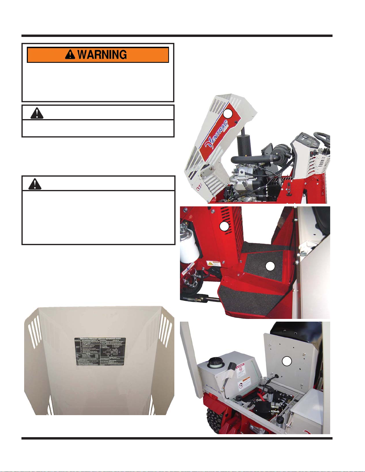
may need to be removed or opened during service.
A - Engine Hood
B - Pump Cover
C - Rear Frame Tunnel Cover
D - Seat Plate
A
B
SERVICE & MAINTENANCE
Proper and timely service of this power unit is critical
to keep the power unit in a safe and reliable operating
condition. Follow the Maintenance Schedule at the end
of the service section. For convenience, a Frequent
Service Reference Chart has been placed on the power unit under the hood as shown in the picture below.
Throughout the Service Section, different access points
are referred to. Below is a list of shields and covers that
C
D
Service - 28
Page 29
SERVICE
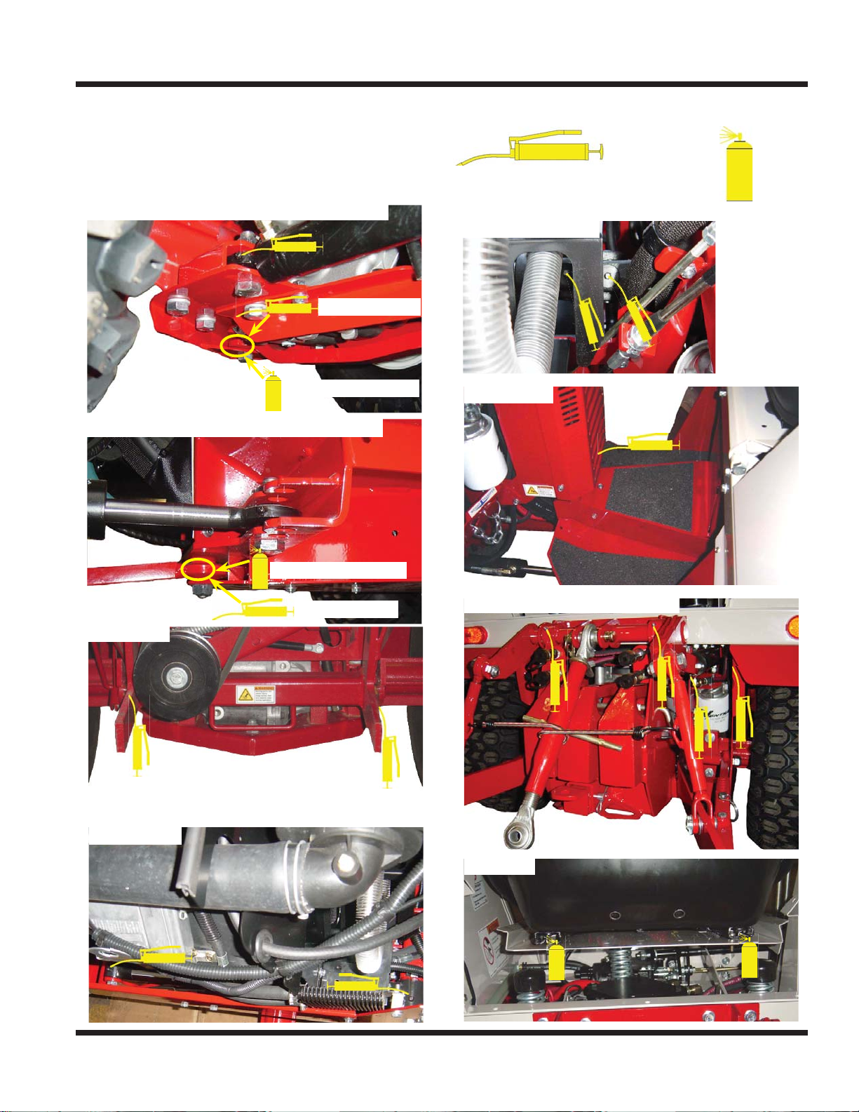
LUBRICATION LOCATIONS
Lubrication is required at the following locations. For
service intervals, see Maintenance Schedule. When
greasing pivot points and bearings, use only one
pump of grease.
Steering Cylinder & Connector Link (Front)
Serial # 1566-
Serial # 1502-1565
Steering Cylinder & Connector Link (Rear)
Grease Spray Lube
Lithium Complex NLGI #2
type grease
Drive Shaft U-Joint
Center Pivot
Front Hitch
Lift Cylinder
Serial # 1502-1565
Serial # 1566-
3 Point Hitch Pivot & Cylinder
Seat Rails
Service - 29
Page 30
A
B
Oil Fill Plug
SERVICE
CHECKING HYDRAULIC OIL LEVEL
Check hydraulic oil level before operating unit when
the hydraulic system is cold. If the hydraulic system is warm, allow 1 hour for the hydraulic system
to cool before checking. If the hydraulic system is
warm when the oil level is checked, it will produce
an inaccurate oil level reading.
1. Park power unit on a level surface.
2. Engage parking brake and shut off engine.
3. Remove ignition key from switch and allow time
for hydraulic system to cool.
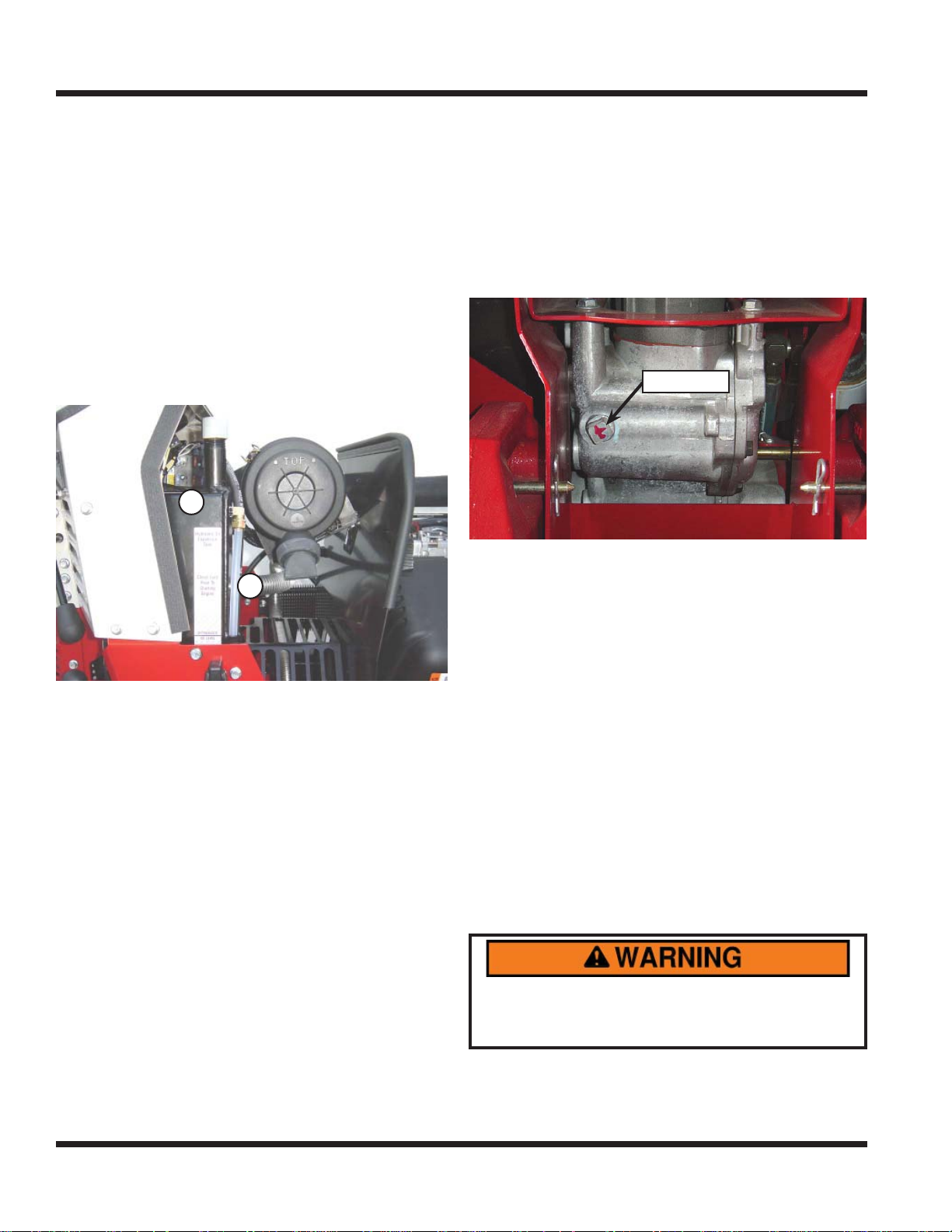
4. The hydraulic tank is located under the hood
near the right side of the dash as shown. (A)
A
B
CHECKING REAR TRANSAXLE OIL
Check the rear transaxle oil level before operating
unit when oil is cold.
1. Park power unit on a level surface.
2. Engage parking brake and shut off engine.
3. Remove the oil fi ll plug from the transaxle and
check to see if oil is even with the bottom of the
oil fi ll hole.
Oil Fill Plug
If oil level is low, add HydroTorq XL synthetic
4.
hydraulic oil until level with bottom of oil fi ll hole.
CHANGING HYDRAULIC OIL AND FILTER
Hydraulic oil and fi lters should be changed at in-
tervals of 2000 hours. Hydraulic oil and fi lters to be
changed by an authorized Ventrac dealer only.
5. Check that the
(B) next to the hydraulic tank is within the proper
range indicated by the oil level decal.
6. If hydraulic oil level is below the checkered area
of the decal, add HydroTorq XL synthetic hydraulic oil until the proper level is reached.
oil level in the plastic sight tube
SERVICING CLOSED LOOP HYDROSTATIC DRIVE
C
IRCUIT
Service or repair must be performed by an authorized Ventrac dealer.
If any part of the closed loop hydrostatic drive circuit
(pump, front drive motor, rear drive motor, or any
of the three 1/2” hydraulic lines connecting them
together) is serviced or replaced, the Ventrac closed
loop drive circuit fi ltration procedure must be per-
formed. This procedure requires a special Ventrac
remote fi ltering tool and must be performed by a
Ventrac authorized technician.
Failure to perform this fi ltering procedure
following a repair can result in component and/or
complete system failure and may void warranty .
Service - 30
Page 31
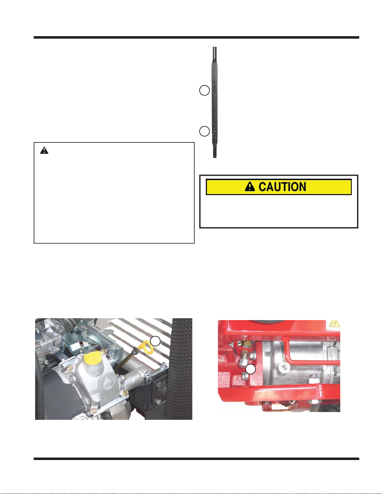
A
B
C
A
SERVICE
CHECKING ENGINE RPM
Check engine RPM’s when engine is warmed up
and not under load.
Observe Tachometer:
• Slow idle (no load) - 1500 +/-50
• Fast idle (no load) - 3600 +/-50
If engine RPM is incorrect, contact your local Ventrac dealer.
CHECKING ENGINE OIL LEVEL
ATTENTION: Avoid damage to your engine.
Failure to check the oil level regularly could
lead to serious damage to your engine if the
engine is run with an incorrect oil level.
• Before operation, check engine oil with the
unit sitting on a level surface.
• Check oil level when the engine is cold
and not running
• Keep oil level between the FULL and ADD
marks.
• Shut off engine before adding oil.
1. Park power unit on a level surface.
2. Engage parking brake and shut off engine.
3. Remove ignition key from switch.
4. Open engine hood to access the engine compartment.
5. Remove the dipstick (A) located on the left side
of the engine. Wipe dipstick with a clean cloth.
7. Check oil level. Level should be
between the Full (B) and Add (C) on
the dipstick.
B
C
8. NOTE: if oil is low, add small
amounts of oil to bring the oil level
no higher than level (B) on the dipstick.
9. If oil level is above (B), drain to
achieve proper level.
10. Install dipstick and close hood.
CHANGING ENGINE OIL AND FILTER
ENVIRONMENTAL HAZARD!
Oil is hazardous to the environment. Dispose of
oil in an approved container at a proper recycle
center.
1. Run engine for 5 minutes to warm up the oil.
2. Park power unit on a level surface.
3. Engage parking brake and shut off engine.
4. Remove ignition key from switch.
5. Open engine hood to access the oil and oil fi lter.
6. Place a drain pan under the oil drain located just
in front of the front transaxle.
7. Remove drain cap from oil drain (A).
A
Install dipstick back into the engine and remove
6.
again.
Service - 31
A
Page 32
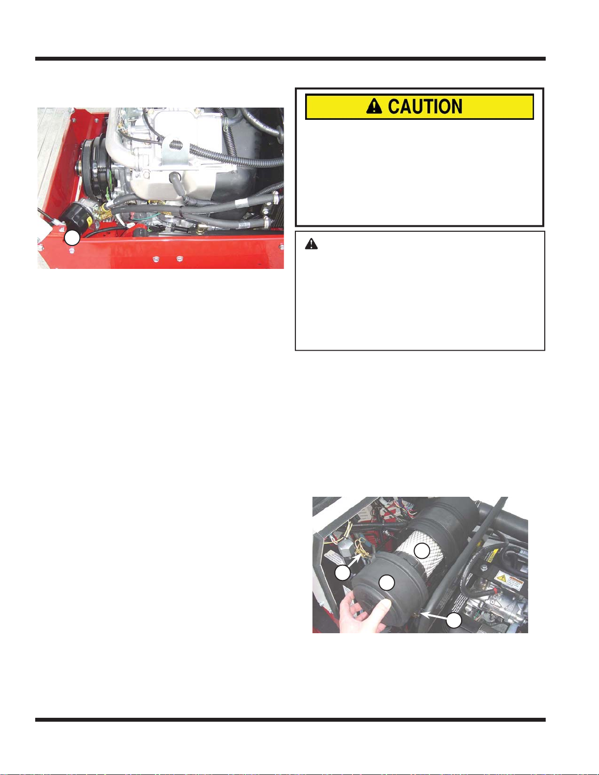
B
A
A
B
C
SERVICE
8. Remove oil fi lter (B) located in front of the left
side of the engine. Turn fi lter counterclockwise to
remove.
B
Wipe the fi lter mounting surface with a clean
9.
cloth.
10. Apply a thin fi lm of clean engine oil to gasket of
oil fi lter.
11. Install new fi lter. NOTE: Turn fi lter clockwise
until fi lter gasket makes contact with the mount-
ing surface. Tighten 1/2 - 3/4 turn after gasket
contact.
12. Install oil drain cap. DO NOT over-tighten.
13. Remove oil fi ll cap.
14. Add oil to engine. (See Engine Owner’s Manual
for proper oil and capacity)
15. Install oil fi ll cap.
16. Start engine and allow to run at slow idle for approximately 2 minutes.
17. Shut off engine.
18. Remove ignition key from switch.
19. Check oil after allowing engine to cool for approximately 2 minutes.
20. Refer to “Checking Engine Oil Level” for proper
procedures on how to check the oil.
SERVICING AIR FILTER ELEMENTS
AVOID ENGINE DAMAGE!
When removing the air fi lter element, an open-
ing directly to the internal parts of the engine is
created.
Be sure that nothing falls into the canister that
could make its way into the engine. Have the new
fi lter element ready to install immediately after the
old element has been removed.
ATTENTION: Avoid damage to your
engine! Improper service to the engine air
fi lter can result in severe engine damage.
• Inspect fi lter daily in extreme heat, dust,
or other severe conditions.
• Never run engine without proper air fi lter
installed.
• Never wash or clean paper fi lter element.
Changing Air Filter Element(s)
1. Park power unit on a level surface.
2. Engage parking brake and shut off engine.
3. Remove ignition key from switch.
4. Allow engine to cool.
5. Open engine hood to access engine compartment.
6. Release both latches (A) on the canister and
unhook latches from the canister housing.
C
A
B
Remove the air fi lter cap (B).
7.
8. Remove and discard the primary fi lter element (C).
9. If necessary, remove and discard the inner safety
air fi lter element. Refer to Maintenance Schedule
for safety air fi lter service interval.
Service - 32
A
Page 33
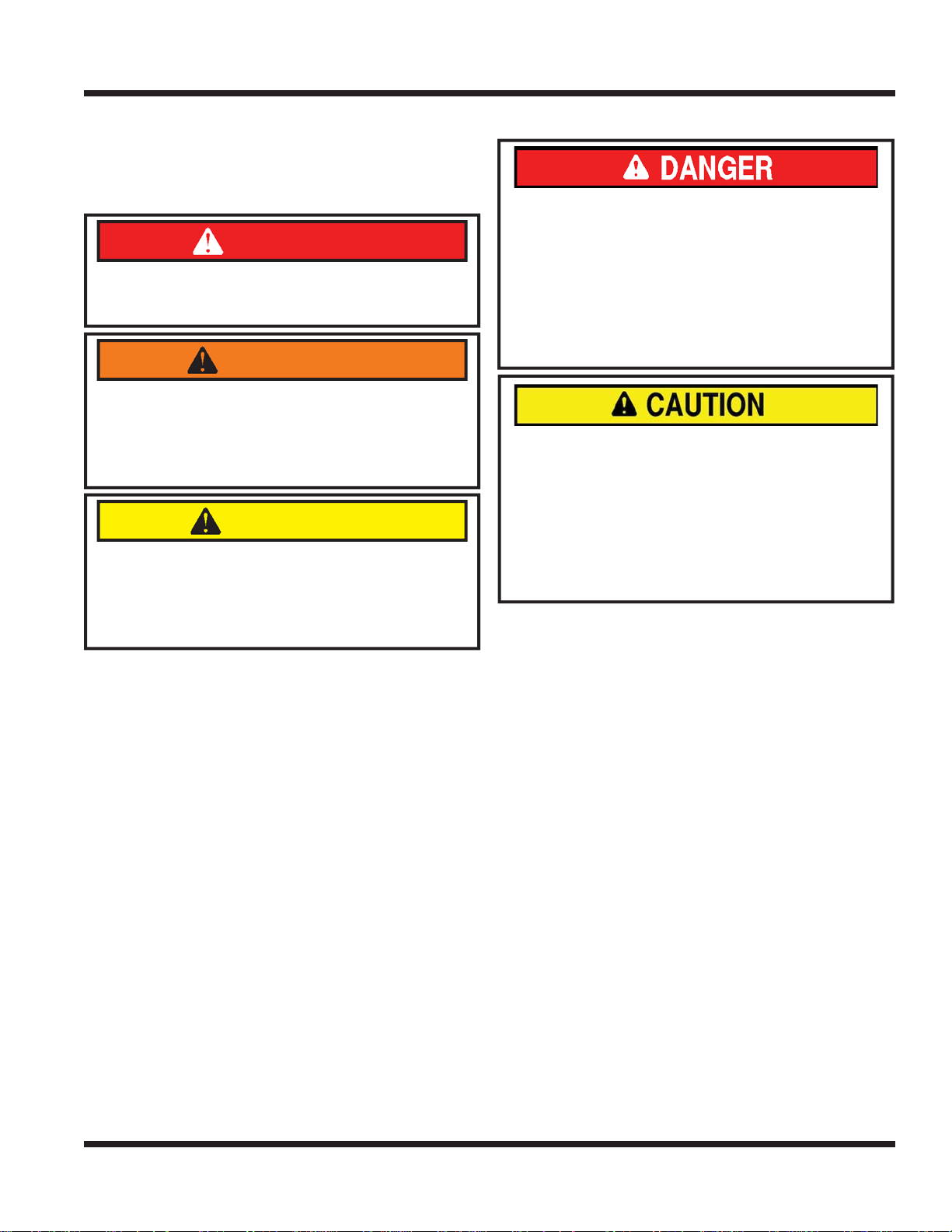
SERVICE
10. Install the new fi lter element(s).
11. Reinstall the air canister cap.
12. Close engine hood.
FILLING THE FUEL TANK
DANGER
Fuel is fl ammable and/or explosive. Follow all
safety instructions in the Fuel Safety section of
this manual and in the engine operator’s manual.
WARNING
Long term exposure to fuel vapors can cause
serious injury or illness. Avoid prolonged
breathing of fuel vapors.
If fuel is spilled on skin or clothing, change clothing
and wash affected skin immediately.
CAUTION
Avoid damage to your engine!
Only use fuel that meets the specifi cations required
for your engine. Refer to the engine operator’s
manual for the proper grade and specifi cations of
fuel for your engine.
1.
Park the power unit on a level surface.
2. Engage the parking brake and shut off the engine.
3. Remove the key from the ignition switch and
allow the engine to cool.
4. The fuel tank cap is located on top of the left rear
fender. Wipe any dust and dirt off the fuel cap
to prevent dirt from falling into the fuel tank, and
remove the fuel cap.
5. Add fuel to the tank until the fuel level reaches
the bottom of the fuel neck. Do not overfi ll. Keep
the fuel nozzle in contact with the rim of the fuel
neck until fueling is completed.
6. Replace the fuel cap and tighten until it clicks.
7. Wipe up any fuels spills and allow fuel vapors to
dissipate before starting the engine.
SERVICING FUEL FILTER
AVOID PERSONAL INJURY!
Avoid personal injury and/or death from fumes,
fi re or explosion when working on fuel related
parts:
• Shut off engine and allow to cool.
• Do not smoke anywhere near the power unit.
• Keep power unit away from fl ames or sparks.
• Work in a well ventilated area.
• Clean up spilled fuel immediately.
AVOID PERSONAL INJURY!
Wear proper personal protective equipment to
protect eyes and hands when working with the
fuel system.
• Let power unit cool before servicing.
• Drain fuel into an approved nonmetallic container.
• Disconnect negative battery cable before
working on the fuel system.
Changing In-line Fuel Filter
1. Turn the fuel shut-off valve to the OFF position.
2. Remove the rear frame tunnel cover.
3. Locate the fuel fi lter inside the rear frame tunnel
area.
4. Loosen the hose clamps and remove the fuel
fi lter.
5. Install the new fi lter with the fl ow arrow pointing
toward the engine.
6. Reinstall the tunnel cover.
7. Turn the fuel shut-off valve to the ON position.
Priming the Fuel System
1. Turn the ignition key to the ON position for about
30 seconds. The operator should hear the fuel
pump operating.
2. Start the power unit. Repeat step 1 if necessary.
*If power unit will not be used after fi lling fuel tank, only fi ll the tank to within
1” (25 mm) of the bottom of the fuel neck to allow room for fuel expansion
from temperature changes. Failure to do so may cause engine fl ooding.
Service - 33
Page 34
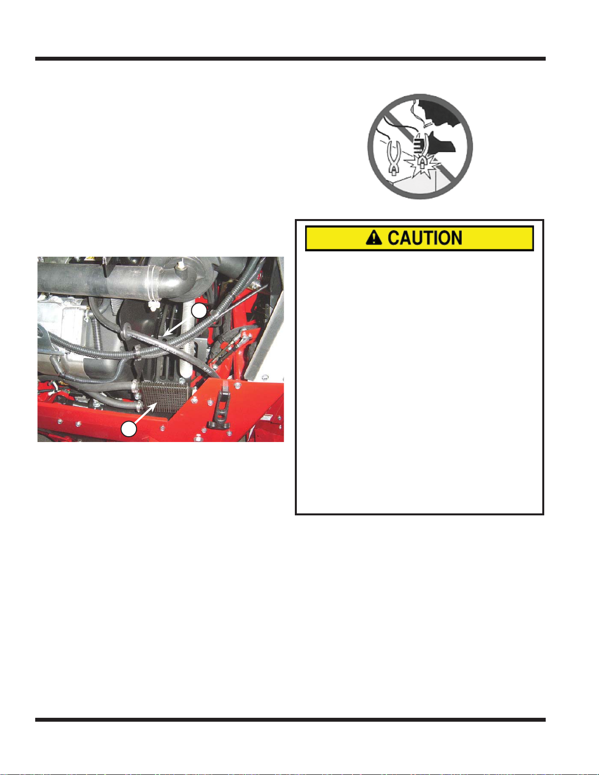
A
B
SERVICE
CLEANING ENGINE COMPARTMENT
& O
IL COOLER
Clean engine compartment daily or prior to each
use, to reduce the risk of engine overheating and
ignition of accumulated debris.
1. Park power unit on a level surface.
2. Engage parking brake and shut off engine.
3. Remove ignition key from switch.
4. Open engine hood to access the engine compartment.
5. Remove accumulated debris from engine compartment, particularly around the drive shaft
cover (A) and rotating screen.
A
B
Clean the oil cooler (B) using a brush or com-
6.
pressed air to remove dust and debris.
SERVICING BATTERY
AVOID PERSONAL INJURY!
Battery electrolyte contains sulfuric acid. It is
poisonous and can cause serious burns.
• Wear eye protection and gloves.
• Keep skin protected.
• If electrolyte is swallowed, get medical atten-
tion immediately.
• If electrolyte is splashed in eyes, fl ush imme-
diately with water for 15-30 minutes and seek
medical attention.
• If electrolyte is splashed onto skin, fl ush
immediately with water and get medical attention, if necessary.
The battery produces a fl ammable and explo-
sive gas. The battery may explode.
• Do not smoke near battery.
• Wear eye protection and gloves.
• Do not allow direct metal contact across bat-
tery posts.
• Remove negative cable fi rst when discon-
necting.
• Install negative cable last when connecting.
REMOVING AND INSTALLING BATTERY
Removing:
1. Park power unit on a level surface.
2. Engage parking brake and shut off engine.
3. Remove ignition key from switch.
4. Tilt the seat plate forward and prop in place.
5. Disconnect the negative battery cable (A).
6. Disconnect the positive battery cable (B).
Service - 34
Page 35
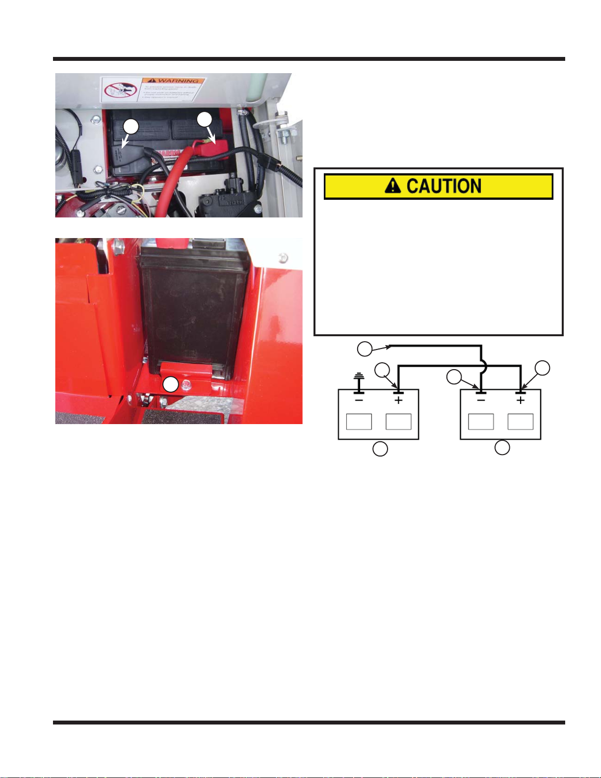
A
B
C
SERVICE
B
A
7. Loosen fastener (C) and remove battery clamp.
6. Rinse the battery with plain water and dry.
7. Clean terminals and battery cable with wire
brush until bright.
8. Apply dielectric grease to terminals to prevent
corrosion.
USING A BOOSTER BATTERY
AVOID PERSONAL INJURY!
The battery produces a fl ammable and explo-
sive gas. The battery may explode.
• Do not smoke near battery.
• Wear eye protection and gloves.
• Do not jump start or charge a cold or frozen
battery. Warm battery fi rst.
• Do not connect the negative booster cable
to the negative terminal of the discharged
battery. Connect at a good ground location on
the engine away from the discharged battery.
C
8.
Slide battery out of battery compartment.
Installing:
1. Slide battery into battery compartment.
2. Install battery clamp over battery fl ange and
fasten. Do not over tighten.
3. Connect positive battery cable to the positive
battery terminal fi rst, then connect the negative
battery cable to the negative battery terminal.
4. Apply dielectric grease to terminals to prevent
corrosion.
CLEANING BATTERY AND TERMINALS
1. Park power unit on a level surface.
2. Engage parking brake and shut off engine.
3. Remove ignition key from switch.
4. Disconnect and remove battery.
5. Wash battery with solution of four tablespoons
of baking soda to one gallon of water. Be careful
not to get the soda solution into the cell.
F
D
A
A - Disabled Power units Battery
B - Booster Battery
Note: If using a vehicle to boost the battery, boosting
vehicle must be shut off.
1. Connect positive booster cable to booster battery positive post (C).
2. Connect the other end of the positive booster
cable to the disabled battery’s positive post (D).
3. Connect negative booster cable to booster battery negative post (E).
4. Connect the other end (F) of the negative booster cable to a metal part of the disabled power
unit’s engine block away from battery.
5. Start the engine of the disabled power unit and
run the power unit for several minutes.
6. Carefully disconnect the booster cables in the
reverse order: negative cable fi rst and then the
positive cable.
E
B
C
Service - 35
Page 36
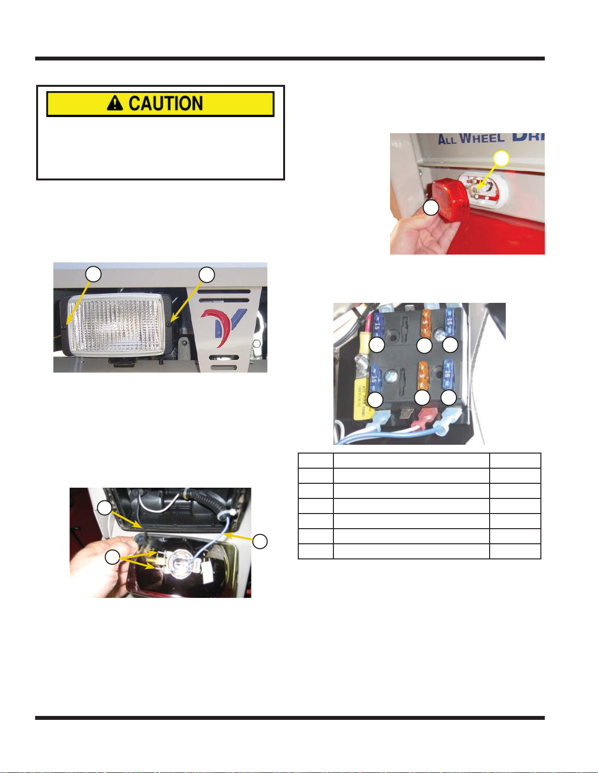
A
A
A
B
A
B
D
C
E
F
SERVICE
CHANGING THE HEADLIGHT BULB
AVOID PERSONAL INJURY!
The headlight bulb contains gases under pressure. The bulb may shatter if the glass is
scratched or dropped. Wear eye protection and
handle bulb with care.
1. Park power unit on a level surface.
2. Engage parking brake and shut off engine.
3. Remove ignition key from switch.
4. Remove the two screws clamping the headlight
cover on (A) and remove cover.
A
A
CHANGING THE TAILLIGHTS
1. Park power unit on a level surface.
2. Engage parking brake and shut off engine.
3. Remove ignition key from switch.
4. Remove the taillight cover (A).
B
5. Pull the old
bulb (B) from
its socket.
A
6. Apply dielectric
grease and install new bulb.
7. Snap taillight
cover back into place.
CHANGING THE FUSES
A
C
B
Disconnect ground wire from the defective head-
5.
light (B).
6. Remove wire loom and shrink wrap from positive
wire (C) and disconnect the positive wire.
7. Remove the defective light bulb from the light assembly by pinching the wire spring fastener.
8. Install the new light bulb and secure with spring
fastener (D).
B
C
D
Place heat shrink tubing over the positive wire.
9.
10. Reconnect the positive and negative wires as
removed.
11. Slide the heat shrink tubing over the connector,
apply heat to shrink, and replace the wire loom.
12. Reinstall the headlight cover.
E
F
D
REF CIRCUIT FUSE SIZE
A Headlights, Taillights, Tach. Light 15
B Gauges, Signal Lights 5
C Rear Auxiliary 15
D Engine Supply 15
E Fuel Pump 5
F Start and PTO Circuits 15
1. Park power unit on a level surface.
2. Engage parking brake and shut off engine.
3. Remove ignition key from switch.
4. Open engine hood.
5. Identify and pull the defective fuse from socket.
6. Push new fuse into socket. Be certain to use the
correct size fuse, or damage may occur to the
power unit.
7. Close engine hood.
Service - 36
Page 37
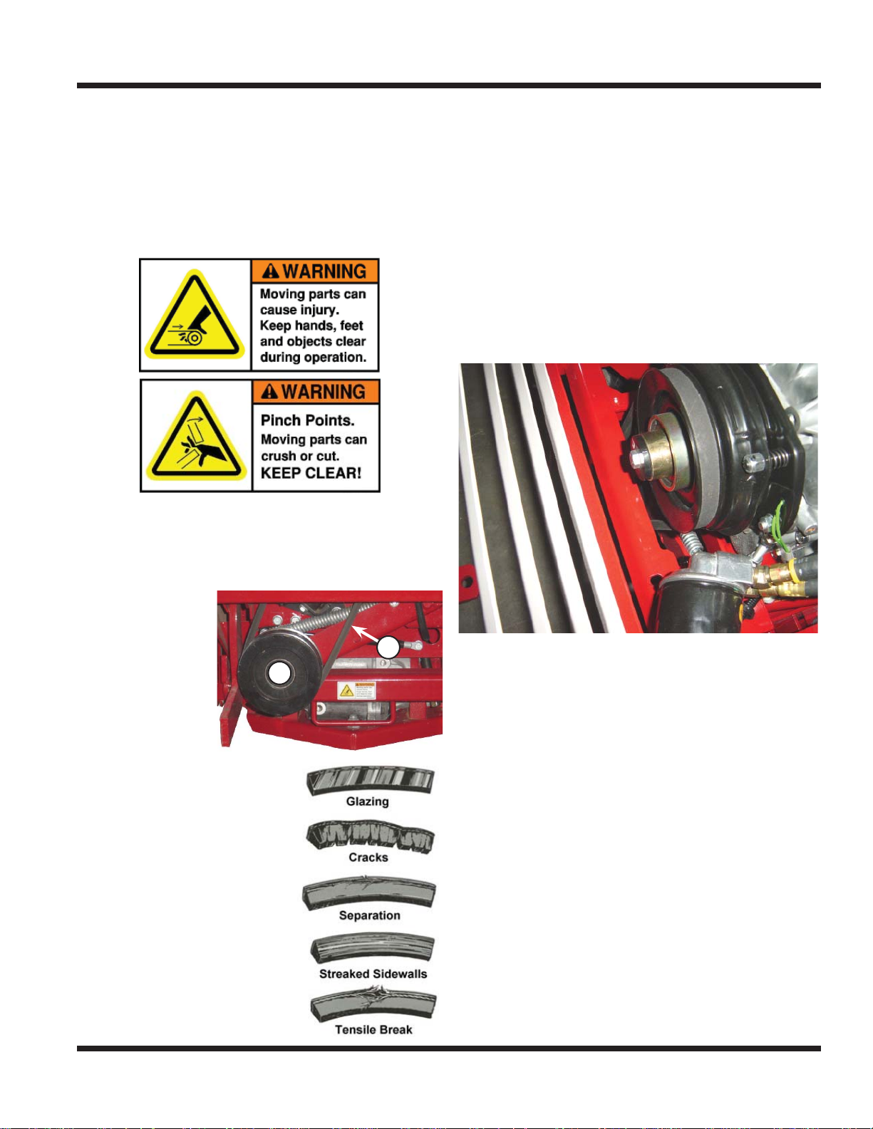
B
A
SERVICE
INSPECTION OF PTO BELT
Periodically checking the PTO belt (A) of this power
unit can prevent sudden failure by fi nding problems
before they cause the belt to break. It is recommended to inspect the PTO belt every 50 hours of
operation, or if a problem is suspected. There may
be a PTO belt problem if there is a squealing or
chattering sound, or the smell of a slipping belt.
1. Park power unit on a level surface.
2. Engage parking brake and shut off engine.
3. Remove ignition key from switch.
PTO BELT REPLACEMENT
1. Park power unit on a level surface.
2. Engage parking brake and shut off engine.
3. Remove ignition key from switch and allow en-
gine to cool.
4. Open engine hood.
5. Rotate the belt tension lever down to release
tension on the PTO belt.
6. Lift up on the PTO idler pulley and remove the
belt from the pulley.
7. Pull belt up between the power unit cross frame
and the clutch to remove.
4. Check the
PTO belt (A) at
the PTO idler
pulley (B).
5. Typical wear on the PTO
belt may result in the
following conditions as
shown at right. If any of
these conditions occur,
then the belt will require
replacement.
A
B
Push the new belt down between the frame and
8.
clutch.
9. Install the belt onto the clutch pulley.
10. Lift up on the PTO idler pulley and install the belt
into the rear groove of the idler pulley.
11. Close engine hood.
Service - 37
Page 38
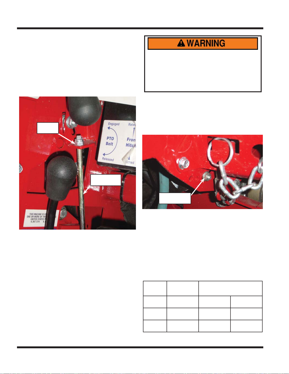
Brake Linkage
Rod
1/4” Lock
Nut
Neutral Adjustment Bolt
SERVICE
PARKING BRAKE ADJUSTMENT
If the parking brake is not holding suffi ciently, the
brake linkage will need to be adjusted.
1. Park power unit on a level surface and block
tires to prevent movement.
2. Move the selector lever out of the park brake
position to relieve pressure on the brake linkage.
3. Tighten the 1/4” lock nut on the brake linkage
rod several turns.
1/4” Lock
Nut
Do not attempt to adjust the neutral position with the
power unit wheels on the ground. During the adjust-
ment process, the power unit could begin to move.
Lift the power unit off the ground and secure with
jack stands to prevent the power unit from moving.
This also allows neutral to be easily determined
when any tire rotation stops.
Start the power unit and adjust engine speed to
3.
approximately 2,000 RPM.
4. Place selector lever in the spring assist to neutral position.
5. Locate the neutral adjustment bolt on the right
base of the steering column.
Brake Linkage
Rod
Check if suffi cient pressure is applied for parking
4.
brake to hold.
5. Continue to adjust the 1/4” lock nut until brake
hold is fi rm. If brake is adjusted to tight, it will be
diffi cult to engage the selector lever in the park
brake position.
NEUTRAL ADJUSTMENT
The power unit should come to a complete stop
when the selector lever is in the park brake (#1) or
the spring assist to neutral (#2) position and the
S.D.L.A. lever is in neutral. If the power unit consistently creeps while in neutral, the neutral position
must be adjusted.
1. Park the power unit on a level surface.
2. Lift the power unit off the ground and secure with
jack stands.
Neutral Adjustment Bolt
Loosen the nut just enough to free the grip of the
6.
bolt from the slot.
7. Move the bolt slightly in either direction until the
tendency to creep stops. NOTE: a small screwdriver can aid in moving and holding the bolt in
place until tightened.
8. Retighten the nut.
NOTE: If unsure of this procedure or your efforts fail
to remedy the problem, contact your Ventrac dealer.
RECOMMENDED TIRE PRESSURE
Tire
All Terrain
Bar
Turf
Single Wheel
8-16 psi
(55-110 kPa)
8-16 psi
(55-110 kPa)
15-20 psi
(103-138 kPa)
(103-117 kPa)
Dual Wheels
Inner Outer
8-10 psi
(55-69 kPa)
8-10 psi
(55-69 kPa)
15-17 psi
(41-55 kPa)
(41-55 kPa)
(69-83 kPa)
6-8 psi
6-8 psi
10-12 psi
Service - 38
Page 39
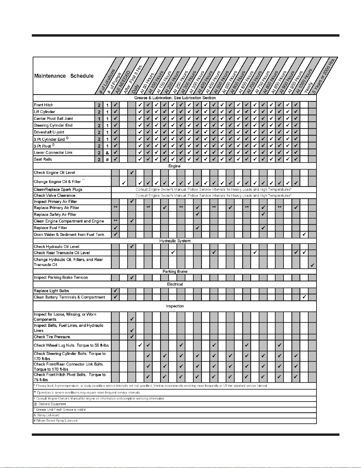
MAINTENANCE CHART
VENTRAC 4100 MAINTENANCE SCHEDULE
This sheet is a guide for recommended Service and Maintenance for the 4100.
Service - 39
Page 40
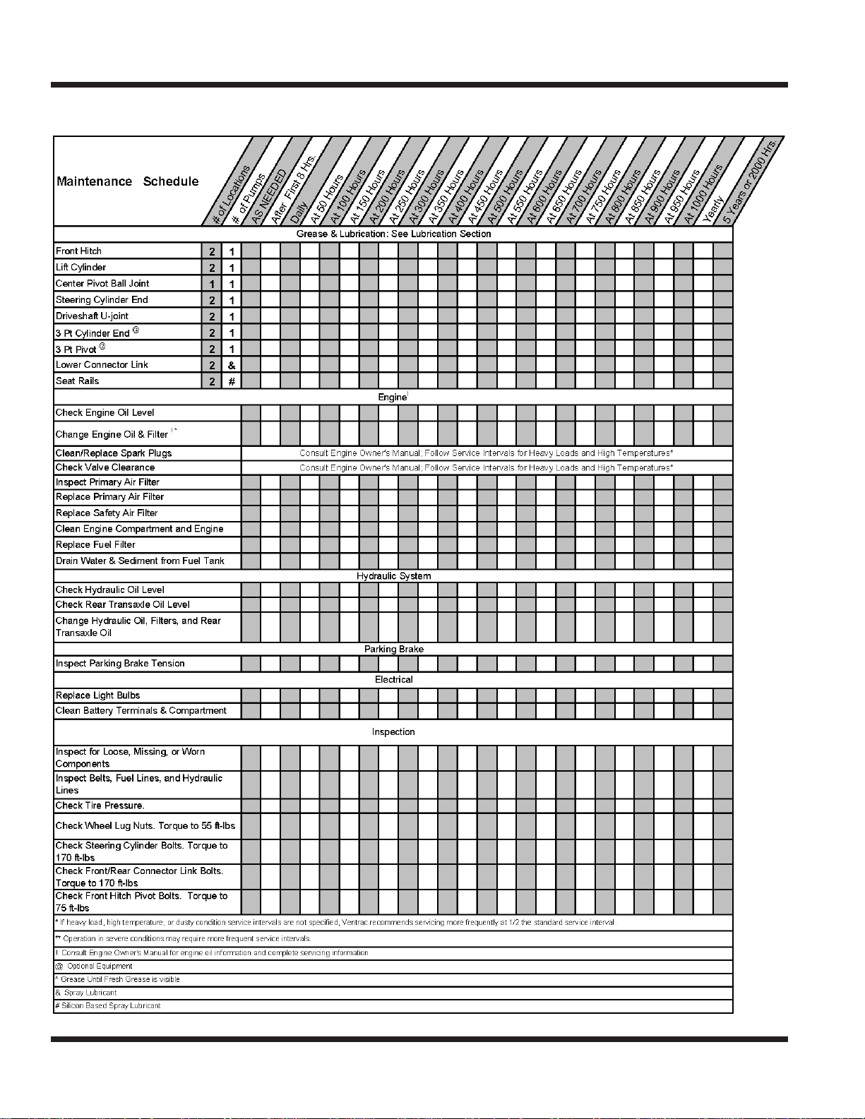
MAINTENANCE CHART
VENTRAC 4100 MAINTENANCE CHECKLIST
This sheet is a checklist for tracking Service and Maintenance for the 4100.
Service - 40
Page 41

TROUBLESHOOTING
ENGINE
SYMPTOM:POSSIBLE CAUSE:
Starter will not engage. Selector lever is not in the park position.
PTO switch is engaged.
Neutral start switch is out of adjustment.
Dead battery.
Blown fuse in start circuit.
Faulty relay in start circuit.
Electrical problem in start circuit.
Engine cranks, but won’t start. Faulty fuel pump.
Insuffi cient fuel level.
Fuel shut-off valve is turned off.
Plugged fuel fi lters.
Obstruction in the fuel line.
Poor engine compression.
Fuel shutoff solenoid not working.
Engine runs rough. Plugged or partially plugged fuel fi lters.
Plugged or partially plugged air fi lters.
Fuel cap vent is plugged or dirty (Serial # 1502-4275).
Stale fuel, dirty fuel, insuffi cient fuel level.
Faulty fuel pump.
Dirty or faulty carburetor.
Engine is low in power. Plugged or partially plugged fuel fi lters (most common).
Plugged or partially plugged air fi lters.
Low cylinder compression.
Dirty or faulty carburetor.
Engine overheats. Debris in engine compartment or engine cooling fi ns.
Dirty oil cooler.
Oil light comes on when running. Low in oil.
Faulty oil sender.
Faulty oil pump.
Engine emits white exhaust smoke. Low engine temperature; Allow engine to warm up.
Engine emits black or gray exhaust smoke. Plugged air intake system.
Engine burning oil.
Dirty or faulty injectors.
Excessive fuel consumption. Plugged air intake system.
Carburetor not functioning properly.
Engine uses excessive oil. Check for leaks.
Incorrect engine oil.
Plugged air intake fi lter.
Worn rings or cylinder walls.
Troubleshooting - 41
Page 42

TROUBLESHOOTING
ELECTRICAL
SYMPTOM:POSSIBLE CAUSE:
Battery does not charge.
Lights do not activate. Blown fuse.
PTO does not engage. Faulty seat switch. NOTE: Operator must be in seat.
Loose or corroded connections.
Broken or loose wire in charge system.
Defective battery.
Defective alternator.
Defective voltage regulator.
Blown light bulb.
Broken wire/connection.
Faulty light switch.
Faulty PTO switch.
Faulty PTO relay switch.
PTO belt failure.
Clutch out of adjustment.
Faulty clutch.
Electrical problem.
HYDRAULIC
SYMPTOM:POSSIBLE CAUSE:
Front attachment fails to lift. Low hydraulic oil.
Excessive load on hitch.
Faulty hydraulic cylinder.
Low hydraulic charge pressure.
Bolt missing from hitch frame or lift cylinder.
Steering is diffi cult. Low hydraulic oil.
Faulty hydraulic cylinder.
Cold temperature. Allow power unit to warm up.
Excessive noise in hydraulic system. Low hydraulic oil.
Cold temperature. Allow power unit to warm up.
POWER UNIT
SYMPTOM:POSSIBLE CAUSE:
Power unit will not move with engine running.
Selector lever is in the park position.
Brake does not release.
Low hydraulic oil.
Pump control linkage is loose.
High/low range shift lever is in neutral.
Suspension seat lock is engaged. (If equipped)
Troubleshooting - 42
Page 43

SPECIFICATIONS
SPECIFICATIONS
ENGINE
Manufacturer . . . . . . . . . . . . . . . . . . . . . . . . . . . . . . . Vanguard
Model Number. . . . . . . . . . . . . . . . . . . . . . . . . . . . . . . . 543477
Type . . . . . . . . . . . . . . . . . . . . . . . . . . . . . . . . . . Gasoline
Cylinders . . . . . . . . . . . . . . . . . . . . . . . . . . . . . . . . . . . . 2
Displacement . . . . . . . . . . . . . . . . . . . . . . . . . . . . . . . . 895 cc
Engine Gross HP . . . . . . . . . . . . . . . . . . . . . . . . . . . . . . . . 31
Operating Range (RPM) . . . . . . . . . . . . . . . . . . . . . . . . . . .1500-3650
Cooling System . . . . . . . . . . . . . . . . . . . . . . . . . . . . . . Air Cooled
ELECTRICAL
Battery . . . . . . . . . . . . . . . . . . . . . . . . . . . . 450 Cold Cranking Amps
Voltage . . . . . . . . . . . . . . . . . . . . . . . . . . . . . . . . . . 12 Volts
Alternator. . . . . . . . . . . . . . . . . . . . . . . . . . . . . . . . . . 50 Amp
POWER TRAIN
Type . . . . . . . . . . . . . . . . . . . . . . . . . . Hydrostatic (All Wheel Drive)
Hydrostatic Transaxle (2) . . . . . . . . . . . . . . . . . . . . . . . . . . Peerless
Fwd Speed (High)* . . . . . . . . . . . . . . . . . . . . . . . . . .10 mph (16.1 kph)
Fwd Speed (Low)* . . . . . . . . . . . . . . . . . . . . . . . . . . 5.2 mph (8.4 kph)
Brakes . . . . . . . . . . . . . . . . . . . . . . . . . . . . . . . . Hydro-Dynamic
Hydraulic Oil Filtration . . . . . . . . . . . . . . . . . . . . . . . 10 Micron & 25 Micron
CONTROLS & INSTRUMENT PANEL
Steering . . . . . . . . . . . . . . . . . . . . . . . . . . . . . . . . . . Power
PTO (Power Take Off) . . . . . . . . . . . . . . . . . . . . . . . . . .Electric w/brake
Throttle Control . . . . . . . . . . . . . . . . . . . . . . . . . . . . . . . .Cable
Directional Control . . . . . . . . . . . . . . . . .Speed, Direction, Lift, Auxiliary (S.D.L.A)
Control Orientation . . . . . . . . . . . . . . . . . . . . . . . . . . . . . . . Hand
Gauges . . . . . . . . . . . . . . . . . . . . . . . . . Tachometer/Hour Meter, Volt
Parking/Emergency Brake . . . . . . . . . . . . . . . . . . . . . . . . . Band Brake
OTHER FEATURES
Turning Radius . . . . . . . . . . . . . . . . . . . . . . . . . . . . . 43” (109 cm)
Standard Tires . . . . . . . . . . . . . . . . . . . . All Terrain (22 x 12-8) (56 x 30-20 cm)
Optional Tires . . . . . . . . . . . . . . . . . . . . . . Turf (22 x 11-10) (56 x 28-26 cm)
Optional Tires . . . . . . . . . . . . . . . . . . . . . . Bar (21 x 11-8) (53 x 58-20 cm)
Headlight . . . . . . . . . . . . . . . . . . . . . . . . . . . . . . Halogen (55 watt)
Attachment System . . . . . . . . . . . . . . . . . . . . . . . . . . . Ventrac Mount
* May vary based on tire size, type, and infl ation.
Specifi cations - 43
Page 44

SPECIFICATIONS
DIMENSIONS
Wheelbase . . . . . . . . . . . . . . . . . . . . . . . . . . . . . . . 43” (109 cm)
Overall Length . . . . . . . . . . . . . . . . . . . . . . . . . . . . . . 79” (201 cm)
Overall Height (top of ROPS bar) . . . . . . . . . . . . . . . . . . . . . . 67” (170 cm)
Overall Width (single tires)*. . . . . . . . . . . . . . . . . . . . . . . . . 48” (122 cm)
Overall Width (dual tires)* . . . . . . . . . . . . . . . . . . . . . . . . . 70” (178 cm)
Weight** . . . . . . . . . . . . . . . . . . . . . . . . . 1,493-1,630 lbs. (677-739 kg)
Venture Products, Inc. reserves the right to change these specifi cations without notice.
* May vary based on tire size, type, and infl ation.
** Weight varies based on engine size, tire options, and optional accessories.
FLUID CAPACITIES
Ventrac 4100 Fluid Capacities
Engine Oil*
Hydraulic Oil
Fuel (Unleaded Gasoline)
4131 Gas 2.4 qt 2.3L
Hydraulic System, Standard Power Unit* 11.4 qt 10.6L
Equipped w/ 3pt Hitch* 11.8 qt 11.2L
Rear Transaxle 4 qt 3.8L
6 Gallons 22.7L
*When Changing both oil and fi lter.
Specifi cations - 44
Page 45

WARRANTY
WARRANTY
LIMITED WARRANTY - VENTRAC TURF EQUIPMENT
Venture Products, Inc. (shall be referred to as V.P.I.) warrants on the terms and conditions herein, that it will repair, replace, or
adjust any part manufactured by Venture Products Inc. and found by Venture Products Inc. to be defective in material and / or
workmanship.
Effective September 1st 2005, Ventrac warranty on power units & attachments (excluding the HG100/HG150 generator) for
residential use only is limited to three (3) years from original purchase date. Ventrac power units & attachments used commercially
or for any income-producing purpose is limited to two (2) years from original purchase date. Ventrac ET200 turbine blower
(turbine only) is limited to two (2) years from original purchase date. Ventrac HG100/HG150 generator is limited to one (1) year
from original purchase date. Ventrac power units & attachments used for rental is limited to 180 days from original purchase date.
(NOTE: All accessories such as: 3-point hitch, foot pedal, dual wheel kit, etc. will be covered under the above warranty periods
as they would apply provided they are installed by an authorized Ventrac dealer.) This warranty may be transferred and will carry
the remainder of the warranty starting from the original purchase/registration date with the dealership and/or V.P.I. In the event that
product/s originally registered as (3) year residential use are to be transferred to a commercial user, the warranty would change to
the remainder of (2) year commercial use starting from the original purchase/registration date with the dealership and/or V.P.I.
If this warranty covers a consumer product as defi ned by the Magnusson-Moss warranty act, no warranties, express or implied,
(including, but not limited to, the warranty of merchantability or fi tness for a particular purpose) shall extend beyond the applicable
time period stated in bold face type above.
If this warranty covers a product used commercially or for any income producing purpose, the foregoing warranties are in lieu of all
other warranties and no representations, guarantees or warranties, express or implied, (including, but not limited to, a warranty of
merchantability or fi tness for a particular purpose), are made by V.P.I. in connection with the manufacture or sale of its products.
The engine warranty is covered by its respective engine manufacturer. Please refer to the engine manufacturer’ s warranty statement
that is included in the owner’s manual.
The Ventrac turf equipment, including any defective parts, must be returned to an authorized Ventrac dealer within the warranty
period. The warranty shall extend to the cost to repair or replace (as determined by V.P .I .) the defective part. The expense of pickup
and delivery of equipment, service call drive time or any transportation expense incurred for warranty repair is the sole
responsibility of the owner and is not covered under warranty by Ventrac and/or V.P.I. V.P.I.’s responsibility in respect to
claims is limited to making the required repairs or replacements, and no claim of breach of warranty shall be cause for cancellation
or rescission of the contract of sale of any Ventrac equipment. Proof of purchase may be required by the dealer to substantiate
any warranty claim. Only warranty work performed and submitted by an authorized Ventrac dealer may be eligible for warranty
credit.
This warranty extends only to Ventrac turf equipment operated under normal conditions and properly serviced and maintained.
The warranty expressly does not cover: (a) any defects, damage or deterioration due to normal use, wear and tear, or exposure; (b)
normal maintenance services, such as cleaning, lubrication, oil change; (c) replacement of service items, such as oil, lubricants,
spark plugs, belts, rubber hoses or other items subject to normal service replacement; (d) damage or defects arising out of, or
relating to abuse, misuse, neglect, alteration, negligence or accident; (e) repair or replacement arising from operation of, or use of
the turf equipment which is not in accordance with operating instructions as specifi ed in the operator’s manual or other operational
instructions provided by V.P.I.; (f) repair or replacement arising as a result of any operation from Ventrac turf equipment that has
been altered or modifi ed so as to, in the determination of V.P.I., adversely affect the operation, performance or durability of the
equipment or that has altered, modifi ed or affected the turf equipment so as to change the intended use of the product; (g) repair or
replacement necessitated by the use of parts, accessories or supplies, including gasoline, oil or lubricants, incompatible with the turf
Warranty - 45
Page 46

WARRANTY
LIMITED WARRANTY - VENTRAC TURF EQUIPMENT
equipment or other than as recommended in the operator’s manual or other operational instructions provided by V.P.I.; (h) repairs
or replacements resulting from parts or accessories which have adversely affected the operation, performance or durability of the
turf equipment; or (i) damage or defects due to or arising out of repair of Ventrac turf equipment by person or persons other than an
authorized Ventrac service dealer or the installation of parts other than genuine Ventrac parts or Ventrac recommended parts.
The sole liability of V.P.I. with respect to this warranty shall be repair and replacement as set forth herein. V.P.I. shall have no
liability for any other cost, loss, or damage. In particular V.P.I shall have no liability or responsibility for: (i) expenses relating to
gasoline, oil, lubricants; (ii) loss, cost, or expense relating to transportation or delivery of turf equipment from the location of owner
or location where used by owner to or from any authorized Ventrac dealer; (iii) travel time, overtime, after hours time or other
extraordinary repair charges or charge relating to repairs or replacements outside of normal business hours at the place of business
of an authorized Ventrac dealer; (iv) rental of like or similar replacement equipment during the period of any warranty repair or
replacement work; (v) any telephone or telegram charges; (vi) loss or damage to person or property other than that covered by the
terms of this warranty; (vii) any claims for lost revenue, lost profi t or additional cost or expense incurred as a result of a claim of
breach of warranty; or (viii) attorney’s fees.
The remedies of buyer set forth herein are exclusive and are in lieu of all other remedies. The liability of V.P.I., whether in contract,
tort, under any warranty, or otherwise, shall not extend beyond its obligation as set forth herein. V.P.I. shall not be liable for cost of
removal or installation nor shall V.P.I. be responsible for any direct, indirect, special or consequential damages of any nature. In no
event shall V.P.I. be liable for any sum in excess of the price received for the goods for which liability is claimed.
There are no representations or warranties which have been authorized to the buyer of the turf equipment other than set forth in
this warranty. Any and all statements or representations made by any seller of this equipment, including those set forth in any sales
literature or made orally by any sales representative, are superseded by the terms of this warranty. Any affi rmation of fact or promise
made by V.P.I. or any of its representatives to the buyer which relates to the goods that are the subject to this warranty shall not be
regarded as part of the basis of the bargain and shall not be deemed to create any express warranty that such goods shall conform
to the affi rmation or promise.
No employee, distributor, or representative is authorized to change the foregoing warranties in any way or grant any other warranty
on behalf of V.P.I.
Some states do not allow limitations on how long an implied warranty lasts or allow the exclusion on limitation of incidental or
consequential damages, so the above limitation or exclusion may not apply to you.
This warranty gives you specifi c legal rights, and you may also have other rights which vary from state to state.
This warranty applies to all Ventrac turf equipment sold in the United States and Canada.
Warranty - 46
 Loading...