

Vent-Axia MVDC-MS, 437634C, MVDC-MSH, 443298B, MVDC-MSH UniFlex Installation Instructions
...Page 1

220
-
240V~50Hz
Lo
-
Carbon
MVDC & SENTINEL
MULTIVENT
RANGE
VENTILATION SYSTEMS
Installation and Wiring Instructions
ORIGINAL ENGLISH MANUAL. DOWNLOAD THE APP HERE:
PLEASE KEEP THIS MANUAL AND READ IN CONJUNCTION WITH THE ILLUSTRATIONS.
Stock Ref. N°
MVDC-MS 437634C
MVDC-MSH 443298B
MVDC-MSH UniFlex 498502
SMV-H 445655B
SMV-HX 495360
SMV-HX CO² 495361
SMV PLUS-H 407849A
SMV PLUS-HX 495362
SMV PLUS-HX CO² 495363
SMV PLUS-H 496186
(Ventair)
X-Units have wireless controls and
Bluetooth capability.
IPX2
Page 2

Installation and Wiring Instructions for the Multivent Multi-Speed Extract Fans.
IMPORTANT:
READ THESE INSTRUCTIONS BEFORE COMMENCING THE INSTALLATION
Do not install this product in areas where the following may be present or occur:
Excessive oil or a grease laden atmosphere.
Corrosive or flammable gases, liquids or
vapours.
Subject to direct water spray from hoses.
All wiring must be in accordance with the current IEE wiring regulations BS7671, or appropriate standards
of your country. Installation should be inspected and tested by a suitably qualified person after completion.
Ensure the mains supply (voltage, frequency and phase) complies with the rating label.
The unit should be provided with a local double pole fused spur fitted with a 3A fuse having a contact
separation of at least 3mm.
Units showing on the rating label incorporate an earth connection for functional purposes only.
Units showing on the rating label have a Protective Earth.
Precautions must be taken to avoid the backflow of gases into the building from the open flue of gas or
other fuel-burning appliances.
Ambient temperatures higher than 40°C
and lower than -20°C.
Possible obstructions that may hinder
access to or removal of the unit.
This appliance is not intended for use by persons (including children) with reduced physical, sensory or
mental capabilities, or lack of experience and knowledge, unless they have been given supervision or
instruction concerning use of the appliance by a person responsible for their safety.
Young children should be supervised to ensure that they do not play with the appliance.
Cleaning and user maintenance shall not be made by children
The installer is responsible for the installation and electrical connection of the unit on site. It is the
responsibility of the installer to ensure that the equipment is safely and securely installed and left only
when mechanically and electrically safe.
All regulations and requirements must be strictly followed to prevent hazards to life and property, both
during and after installation, and during any subsequent servicing and maintenance.
Certain applications may require the installation of sound attenuation to achieve the sound levels required.
The unit must not be connected directly to a tumble drier.
The exhaust grille should be located in accordance with building regulation and be at least 300mm away
from any flue outlet.
This product and associated duct installation should be carried out in accordance with the Domestic
Ventilation Compliance Guide.
Models that support Radio and Bluetooth communication the below applies
Bluetooth variants contain FCC ID: S9NSPBTLERF
Bluetooth LE: -12dBm EIRP (63μW), nominal 2450MHz.
Bluetooth v4.1 compliant
Bluetooth and radio variants obtained RED certificate: No. 0051-RED-0011 REV. 0
Zirconia Wireless: -14dBm EIRP nominal 868MHz.
The manufacturer hereby assure that this type of Bluetooth radio and 868MHz radio
equipment complies with RED Directive 2014/53 / EU
The full text of the EU Declaration of Conformity can be found at the following URL:
https://www.vent-axia.com/range/centralised-mechanical-extract-ventilation-mev
2
Page 3

INTRODUCTORY NOTES
The MVDC & Sentinel Multivent units are designed for simultaneous extract ventilation of multiple wet
rooms such as bathrooms, kitchens and toilets. The units use a highly efficient backward curved centrifugal
motor impeller set and are designed for continuous 24-hour use.
Depending on the model, they feature either 3 or4 settable speeds and can be configured to change speed
based on a wide range of sensor or control inputs as depicted below
Model MVDC-MS MVDC-MS H
Speeds 3 3 4 4 4 4 4 4
Max airflow
m3/hr (0Pa)
Switched Live Input
(LS)
RS485
Connectivity
Analogue Input
0-10V
Digital Input Yes Yes Yes Yes Yes Yes Yes Yes
Humidity Sensor No Yes Yes Yes Yes Yes Yes Yes
430 430 463 463 463 573 573 573
Yes Yes Yes Yes Yes Yes Yes Yes
No No Yes Yes Yes Yes Yes Yes
Yes Yes Yes Yes Yes Yes Yes Yes
SMV
H
SMV
HX
SMV
HX Co2
SMV Plus H SMV Plus
HX
SMV Plus
HX Co2
CO2 Sensor No No No No Yes No No Yes
Wireless Receiver No No No Yes Yes No Yes Yes
The units can be precisely programmed to determine how they respond to changes in sensor values or the
status of the various signal inputs. The units will run at a normal flowrate until a sensor or input change
causes it to change speed. In the case of the Switched Live and Digital inputs the units will perform a step
change in speed to the appropriate new level. In the case of the Analogue inputs, Humidity Sensor and
CO2 sensor the unit can be programmed to give a proportional response to the change in conditions.
INSTALLATION
Position the unit, taking into consideration the position of the rooms to be ventilated, the exhaust position
and the electrical services. Ensure there is adequate access for installation and maintenance.
If the unit is sited in the heated void of the dwelling a condensate drain should not be necessary.
When sited in a cold void, consideration should be given to fitment of a condensate drain. Alternatively, the
unit and ducting can be externally insulated to minimize condensation within the units housing.
To reduce the system resistance in your duct system, and therefore lower the speed, power consumption
and noise of the fan, follow these guidelines:
1.1. Keep the length of duct runs to a minimum, particularly the exhaust duct run.
1.2. If you need to use flexible ducting, make sure that it is fully extended and not crushed,
sagging or torn.
1.3. Try to minimize the use of diffusers/valves by having similar length duct runs to the inlets.
1.4. The bend radius (measured to the inside of the bend) should be at least 1x the duct diameter.
1.5. Avoid having any bends, filters or other obstructions within 250mm of the fan inlets and outlet.
1.6. Set the valves to their maximally opened positions for a minimal pressure drop.
Securely mount the unit through the mounting holes on the casing using appropriate fixings for the
mounting substrate. It is recommended that anti-vibration mounts, acoustic mat or rubber bushes are used.
Fixings (not supplied) to be capable of securing 4 x the weight of the unit. Unit weight: 4.1kg
3
Page 4

To maintain the IPx2 rating of the unit, the unit must NOT be mounted with the cover removal slots
facing upwards, or at an angle where they are visible from above.
All other orientations are acceptable.
See the dimensional details below for the mounting hole positions.
-Spigot diameters are 125mm
4
Page 5

i. Base mounted Installation with ducting radiating out horizontally.
ii. Vertically mounted Installation with the exhaust spigot at top. The electrical connections must
come out of the bottom of the unit in order to maintain the water ingress protection.
5
Page 6

iii. Ceiling mounted Installation with ducting radiating out horizontally.
WIRING
WARNING:
THE UNIT AND ANCILLARY CONTROL EQUIPMENT MUST BE ISOLATED
FROM THE POWER SUPPLY DURING THE INSTALLATION / OR
MAINTENANCE. THIS UNIT MUST BE EARTHED.
1. To remove the cover, use a coin or similar; depress the retaining tabs via the slots in the side of the
unit.
2. With the power off, connect a suitable mains power cable from a switched, fused spur to the screw
terminal block. Use the cable clamps and clip provided to secure the lead.
3. Two mains voltage Live Switched (LS1 and LS2) connections are provided and can be used to
trigger a change in speed. Common inputs would be from a bathroom lighting circuit. When
commissioning the unit, a delay on timer and an overrun timer can be selected and adjusted in the
software using the buttons and screen. See Commissioning section on page 9 of this document for
details.
4. The switched live output (230Vac) from any other switch or controller, (such as a simple latching pull
cord or push button switch, humidistat or PIR detector) can be connected to the LS terminal instead
of connecting to a lighting circuit.
5. Important: Use 4-core, low voltage, twisted pair, telecoms type cable for accessories (Vent-Axia part
number 459931). Accessories are connected via the IO (Input Output) PCB; see the Low Voltage
Connections diagram. Use the cable clamp and grommet provided.
6. There are no delay-on or overrun timers with the volt-free connection as the controller should
determine when the fan is running at Boost or Normal speeds. Use the LS connection described
above if you want a timer.
Units showing on the rating label incorporate an earth connection for functional purposes only.
7.
Units showing on the rating label have a Protective Earth.
8.
6
Page 7
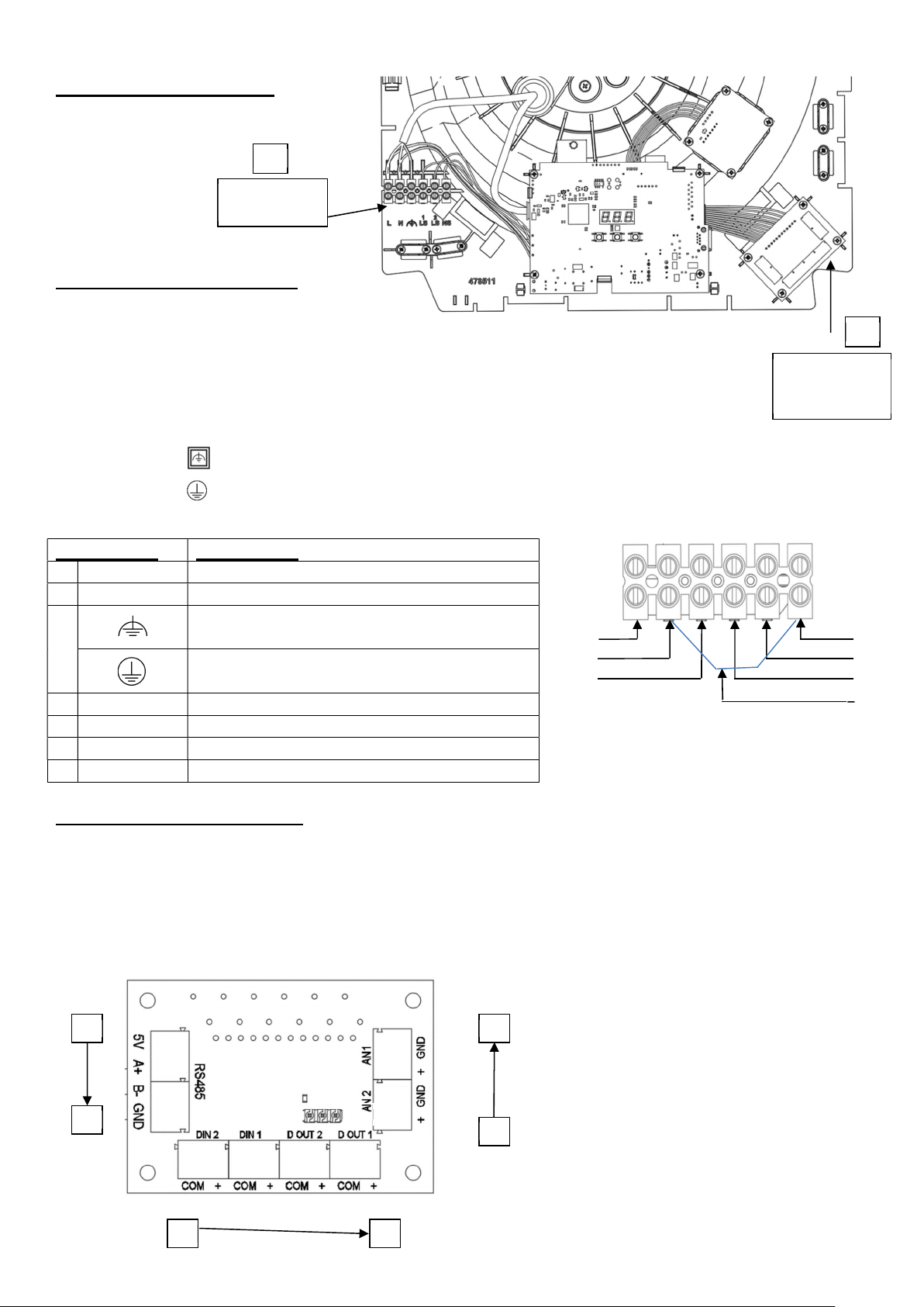
Connection
Description
1 L Live (220
-
240Vac)
2 N
Neutral
4 LS1
Live Switched 1, (220
-
240Vac), isolated
5
LS2
Live Switched 2 (220
-
240Vac), isolated
7 N
+ NS
Link Wire
A P
D
E L
M
7
CONNECTION DIAGRAM
A
Main power
connections
A: Main power connections
The LS1, LS2 and NS terminals are
electrically isolated.
Note: Neutral link between 2 & 6 should be removed if different RCD protection circuits are used
for mains power a & Live Switch connections.
Note: Ensure all live & neutral are isolated before servicing.
Low voltage
connections,
if fitted
Units showing on the rating label incorporate an earth connection for functional purposes only.
Units showing on the rating label have a Protective Earth.
Functional Earth
3
Protective Earth
1
2
3
6
NS Neutral Switched, isolated
B: Low voltage connections
For best performance use 4-core,
low voltage, twisted pair, telecoms type
cable for accessories.
(Available from Vent-Axia part number 459931).
ON OFF
7
B
6
5
4
Page 8
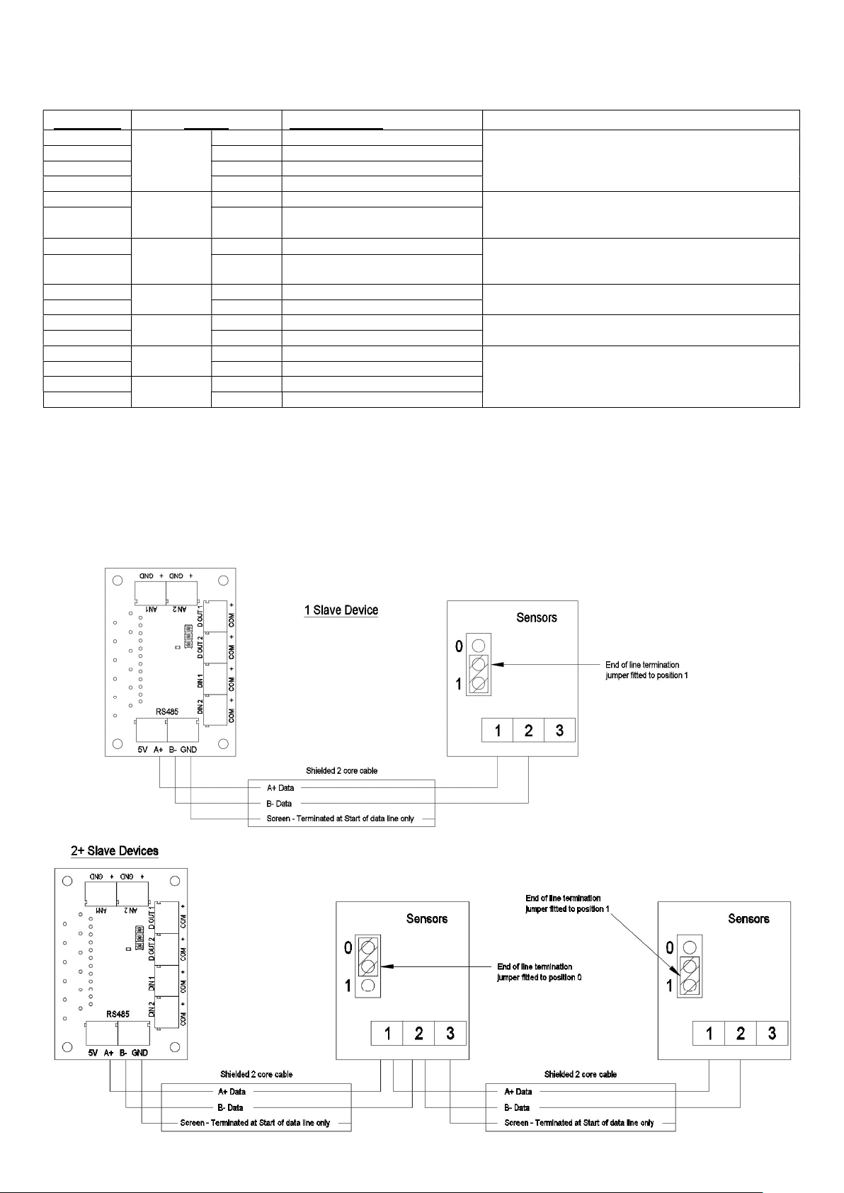
Position
Label
Description
Action
a power supply
a power supply
A
B A+ Data
C B- Data
D GND Ground
E
F + Digital input 2
G
H + Digital input 1
I
J + Digital output 2
K
L + Digital output 1
M
N GND Ground
O
P GND Ground
RS485
D IN 2
D IN 1
D OUT 2
D OUT 1
AN 2
AN 1
5V 5V Output, Max 250mA
COM Digital input common
COM Digital input common
COM Digital output common
COM Digital output common
+ Analog input 2
+ Analog input 1
RS485 communication to wired accessories.
Data connection (B, C) if available.
The 5V and Ground connections are available on all units.
Go to Boost speed (Min.1V, max. 6V).
The 5V output from the RS485 connection can be used as
Go to Low speed (Min.1V, max. 6V).
The 5V output from the RS485 connection can be used as
Unpowered Boost indicator Switch
(Switching 6V 50mA max)
Unpowered LED fault indicator switch
(Switching 6V 50mA max)
0-10V analogue input.
Two user settable voltage thresholds with two user settable
actions. The unit will run at Normal when supplied voltage is
between the two thresholds.
RS485 Wired inputs
The RS485 terminals are used to connect compatible sensors and switches.
The connection allows sensors be daisy chained to simplify wiring. The maximum length of cable run from
the unit is limited to 250m. Once accessories are wired to the unit, they must be paired to the unit to
function correctly.
RS485 Wired input connection diagram
8
Page 9
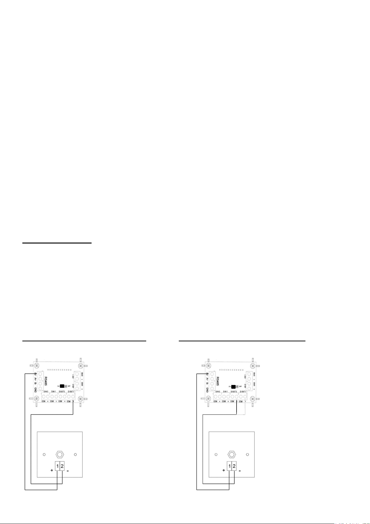
RF868 Wireless inputs
Units that contain a Wireless receiver can be paired with compatible sensors, these can be mains or battery
powered depending on the sensor.
A maximum of 15 wired and wireless sensors can be connected to a single unit.
Pairing sensors
To pair the unit with a wired or wireless sensor:
- Press the Mode button to turn on the display.
- Press and hold the Mode button until the LED illuminates solid White
- Release the mode button, the LED will flash White to indicate that it is in pairing mode.
The unit will remain in pairing mode for 1 hour, or until the mode button is pressed again.
- Activate the pairing function on the sensor to be paired (see the instructions that came with the
sensor).
- When a sensor is paired the total number of paired devices is displayed on the unit.
Removing sensors
To remove paired sensors, the unit must be reset. Caution, this will reset all values back to factory default.
- Press the Mode button to turn on the display.
- Press and hold the Mode button until the LED illuminates solid Red
- Release the mode button, the LED will stay Red.
- Pressing the Mode button again will confirm the reset command. If a reset is not wanted, leave the
unit until the command times out and the LED turns off.
C: Sensor priorities
The unit set the motor speed based on the source in the following order:
User override
LS inputs (1 and 2)
Digital inputs (1 and 2)
Sensor override: The Sensor override action is decided based upon the Sensor input (Humidity Sensor, Co2
sensor, Analog inputs) whichever sets the motor to run in Highest speed.
Default speed (run in normal speed)
Note: At each priority state, if more than one inputs are active (e.g. Digital input 1 and 2 are active), then
motor will always run at a speed from the input which has highest speed level.
Example - LED Fault Indicator Connection Example - LED Boost Indicator Connection
9
Page 10
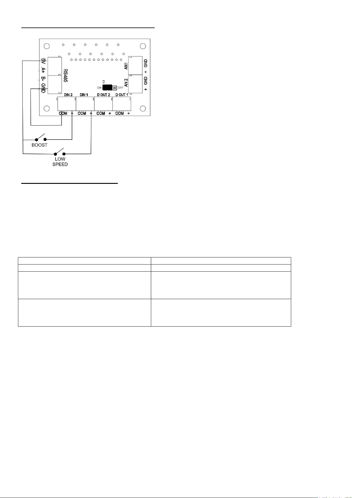
Low Voltage Switch’s – Boost & Low Speed
FEATURE DESCRIPTIONS
If compatible, the unit can be controlled via the Bluetooth linked App. This is only available on Multihome
Wireless units.
Comfort mode
If Comfort mode is enabled the unit will behave as follows to all LS inputs:
Trigger Action
LS input active less than 5 minutes No action (continue to run at Normal speed)
Once LS input is removed, fan will run at user
LS input active more than 5 minutes but less
than 20 minutes
LS input active more the 20 minutes
The above applies to all LS inputs. The times are not adjustable by the user.
Delay On
A delay can be set so that the unit will not respond to an input until after the set delay has elapsed, applies to LS
inputs only.
Overrun Timer
The unit can be set to run for a defined period after the input is removed, applies to LS inputs only.
Humidity – Rapid rise*
Rapid Rise humidity response functions to detect rapid rises in humidity when the ambient %RH is under the threshold
setting. If a rapid rise is detected the fan will boost until the humidity lowers again.
Humidity – Ambient response*
When ambient response is enabled the threshold set point is modified based on the ambient temperature. This helps
to prevent nuisance boosting of the unit as temperatures changes during the day.
Humidity – Threshold*
The unit will boost when the RH is above the threshold set point.
10
selected speed for the length of time LS was
present plus the set over-run time (if over run is
enabled).
Unit will Boost after 20mins.
Once LS input is removed, fan will run at user
selected speed for 20 minutes plus the set over-
run time (if over run is enabled).
Page 11

CO2 threshold Boost / Purge*
The unit will go to Boost / Purge when the detected CO2 level exceeds the set thresholds.
Analogue inputs
Both analogue inputs have adjustable low and high trigger voltages within the 0-10V range.
The response to being above or below either of the threshold voltages is user settable.
Note: The display doesn’t show a decimal point, for example at threshold voltage of 5.2V,
is displayed as “52” on the unit.
Digital Inputs
The unit can be set to change speed (selectable), based on whether the digital inputs are above or below the
threshold voltage. See the table of Low Voltage Connections for details.
Display Lock
To protect the settings on the MEV unit a pin code can be enabled via the main menu.
Once the lock function has been enabled the Pin code can be set.
The 3-digit pin is A to F, 0 to 9, and the default is LoC.
* If external RH or CO2 sensors are fitted via RS485, they will have priority over the internal
sensors, their value will also be displayed on the unit in preference to the internal sensor.
UNIT ADJUSTMENT
1. Commissioning and configuration on all products is supported
by the 3 digit user interface and associated push buttons.
2. When powered on, the unit will display the firmware revision number, after a few seconds the unit
will display the first option in the menu structure (see below).
3. The display will enter standby mode after defined timeout (default 10min) or user selects “END”
option in menu, press the Mode button to turn the display back on.
4. Changes to the settings can be made
via the + and – buttons, the Mode button will
accept changes and move onto the next menu option.
5. When setting the speeds, there is an internal logic: Low<Normal<Boost<Purge.
I.e., Boost is always higher than Normal.
6. The actions for each of the Live Switched (LS), inputs are selectable. The setting for delays and
over run timers are applicable to all inputs.
7. To restore factory settings, Press and hold “Mode” button for 10 seconds
11
Page 12
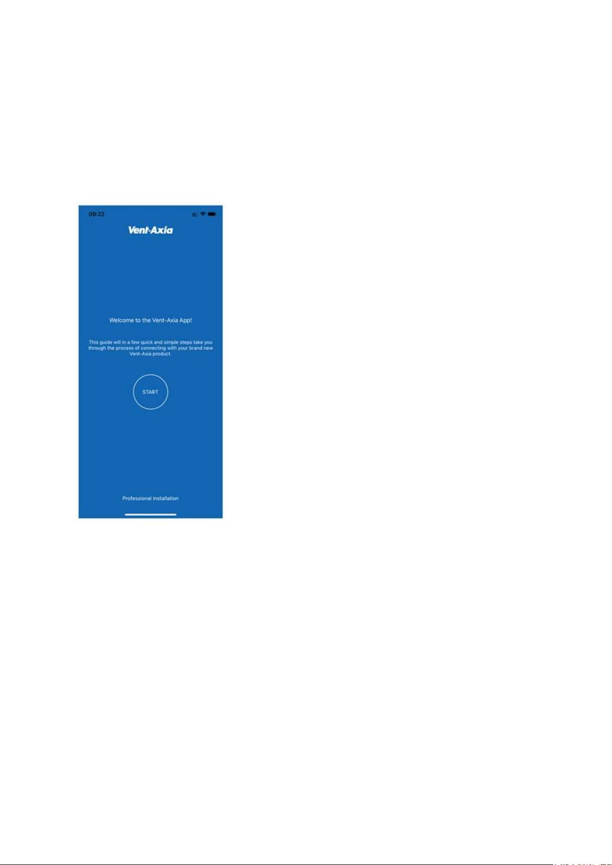
Wireless units can be commissioned via the Bluetooth connected App.
Links to the App are shown on the cover page of this manual. The App must be installed before a
connection to the unit is possible.
Bluetooth Pairing
To enable Bluetooth pairing on the unit:
- Press the Mode button to turn on the display
- Press and hold the Mode button until the LED illuminates solid Blue
Release the mode button, the LED will flash Blue to indicate that it is in pairing mode.
- Follow the instruction on the App to connect to the unit.
12
Page 13

User Configurable Parameters
Display
Function
text
Lxx Low speed 1 to 97% motor speed 10%
nxx Normal speed 2 to 98% motor speed 35%
bxx Boost speed 3 to 99% motor speed 70%
Pxx Purge Speed 4 to 100% motor speed 100%
LS1 Live switch 1 Low, Boost or Purge speed Low
LS2 Live switch 2 Low, Boost or Purge speed Boost
LS3 Live switch 1&2 Low, Boost or Purge speed Purge
c-n Comfort mode Comfort mode - yes or no No
d-n Delay On Delay on - yes or no No
dxx Delay On time Delay to boost duration 1 to 60 minutes 10m
o-n Overrun Overrun - yes or no No
oxx Overrun time Overrun duration 1 to 60 minutes 10m
r-n Humidity – Rapid Rise Rapid rise - yes or no Yes
A-n Humidity – Ambient Response Ambient response - yes or no No
hxx Humidity threshold Ambient response threshold 40 to 90% RH 70%
C2b CO2 threshold boost
C2P CO2 threshold purge
A1LA Analogue 1 - low action Low, Normal, Boost or Purge speed Low
A1HA Analogue 1 - high action Low, Normal, Boost or Purge speed Purge
A1tL Analogue 1 - low threshold Analogue Input Threshold Low 1 - 99 15
A1tH Analogue 1 - high threshold Analogue Input Threshold High 1 - 99 75
A2LA Analogue 2 - low action Low, Normal, Boost or Purge speeds Low
A2HA Analogue 2 - high action Low, Normal, Boost or Purge speeds Purge
A2tL Analogue 2 - low threshold Analogue Input Threshold Low 1 - 99 15
A2tH Analogue 2 - high threshold Analogue Input Threshold High 1 - 99 75
D1 Digital input 1 Action Low, Boost or Purge speeds Low
D2 Digital input 2 Action Low, Boost or Purge speeds Purge
unl Unlock code Turn on/off the menu lock - - -
PIn Display Pin 3 characters A to 9 LoC
dtxx Display time Adjust how long the display is illuminated 1-99 min
rot Rotate display Invert the display rot
hu Humidity Show the current internal humidity %
tu temperature Show the current internal temperature °C
CO2 CO2 Show the current CO2 level PPM
end end End of menu (loop to start)
Boost threshold 650 – 4950 PPM
in increments of 50
Purge threshold 700 – 5000 PPM
in increments of 50
Selections Default
100
195
If the unit being commissioned is not fitted with the relevant hardware, the associated menu options will not
be available.
CO2 Calibrations
The following instructions describe the actions required to calibrate the CO2 sensors used within
the MEV unit (if fitted), and the Room Sensor accessories in two steps:
1. MEV Unit – Internal sensor
Step 1 can be done by either Exposure method or Measurement method, the baseline step 2 is
actioned once either step 1 options are complete.
13
Page 14

1.1 Exposure method step 1
Exposure method assumes that the outside CO2 concentration is 400 PPM in the rooms in
which the MEV extracts air from, the Rooms must be well ventilated by opening any external
windows and doors for 10 to 15 minutes. The room must remain well ventilated and unoccupied
until after the baseline step has been actioned.
1.2 Measurement method step 1
If the Engineer has a calibrated CO2 meter, they simply need to measure the CO2 in
accordance to the CO2 meters instructions within the rooms the MEV extract air from.
Measurement taken from each room should be recorded and then averaged.
Example: Room 1 – 450ppm + Room 2 440ppm + Room 3 – 460ppm = 1350ppm / 3 = 450ppm
The averaged value is then used during the baseline step.
1.3 Baseline step 2
MEV On-Board display method
Within the MEV menu there is rEF which has a default value of 40 (=400ppm), if using the
Exposure method of calibration this does not need to be changed.
For the Measurement method of calibration, the value within rEF should be changed to the
recorded average PPM, using the example value this would be 45 (=450ppm).
With the rEF value set as required, the user should navigate to the cAl menu and use the
up/down arrow to select y (=Yes). The status LED will start blinking Magenta colour signifying
the start of the calibration, the MEV will repeatedly read the CO2 sensor for 3 minutes to obtain
a stable reading, once the status LED stops flashing the Calibration value has been set.
MEV Mobile App method
Once the app is connected to the MEV navigate to the CO2 screen from the home screen. On
the CO2 screen enable Set CO2 calibration at the bottom of the page.
An additional slide bar will appear with a default value set to 400ppm, if using the measurement
method, the value should be changed to match the measured averaged recorded PPM, using
the example value this would be 450ppm. For the Exposure method the value should be
unchanged at 400ppm.
With the value set the Save button should be pressed in the top right of the screen to start the
calibration process, the status LED will start blinking Magenta colour signifying the start of the
calibration, the MEV will repeatedly read the CO2 sensor for 3 minutes to obtain a stable
reading, once the status LED stops flashing the Calibration value has been set.
2. Room Sensor Calibration
The Room sensor can only be calibrated using the Exposure method and will have Auto
Background Calibration (ABC) by default.
2.1 Exposure method Step 1
Exposure method assumes that the outside CO2 concentration is 400 PPM in the room which
the Sensor is fitted, the room must be well ventilated by opening any external windows and
doors for 10 to 15 minutes. The room must remain well ventilated and unoccupied until after the
baseline step is complete.
2.2 Baseline method – Step 2
With the Room sensor paired to the system the status LED will be Green when the button is
pressed, in this condition the button should be pressed and held (8 Seconds) until the status
LED is Magenta, the button should then be released and the LED will be blinking Magenta to
signify the start of the calibration process, the room should be unoccupied once the calibration
has started and should remain so for 5 minutes. During the calibration process the Room
sensor will repeatedly read the CO2 sensor for 3 minutes to obtain a stable reading, once the
status LED stops flashing the Calibration value has been set.
14
Page 15
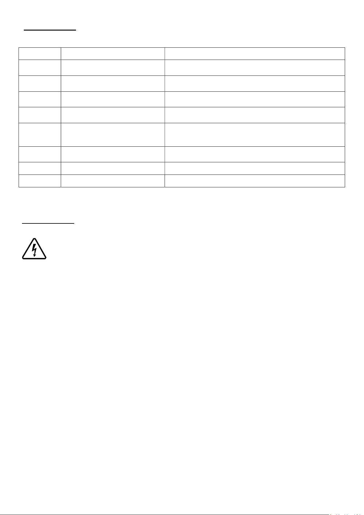
FAULT CODES
offline/Lost
RF/RS485 is offline/Lost
Re-pair the sensor to the unit, see page 10.
If the MEV unit detects a fault it will display an error message on the HMI display:
Fault Code Description
F01
F02 Motor Fault – No RPM
F03
F04
F05
Control fault – Unit failed startup
check
Humidity/Temp sensor Fault –
No value – internal sensor
CO2 sensor Fault – No value –
internal sensor
Temp or Humidity sensor
connected via RF/RS485 is
Turn the power off and on again.
Check that the impellor has free movement.
Check internal motor wiring.
Contact tech support, scroll part.
Check the internal wiring to the sensor
Check that the sensor is turned on.
Re-pair the sensor to the unit, see page 10.
F06
F07 4-Way Speed Switch SSU offline or lost – Please reconnect
F08 AIM (Alarm Interface Module) AIM Sensor triggered / offline or lost – Verify Issue
If a fault persists, contact your local technical support, see the back cover of this manual for details.
CO2 sensor connected via
Check that the sensor is turned on.
SPARE PARTS
WARNING: THE FAN AND ANCILLARY CONTROL EQUIPMENT MUST BE
ISOLATED FROM THE POWER SUPPLY DURING PART REPLACEMENT.
1. Individual faulty parts should not be replaced due to complexity of assembly. Only the full scroll
assembly is replaceable.
2. To remove the scroll assembly, isolate the power, then use a coin or similar to depress the cover
retention clips and remove the cover.
3. Disconnect and remove the power supply and signal leads.
4. Remove the scroll assembly by unscrewing the two screws and unclipping the clips in the opposite
two corners and lift the scroll assembly out of the housing.
5. The fan has sealed for life bearings, which do not require lubrication. Expected service life is at least
45,000 hours continuous running.
6. Upon reassembly, check all fixings are tight and secure.
For a replacement Scroll assembly please contact:
Vent-Axia Technical support
+44 (0)344 856 0594
Email: [email protected]
Please take note of the model’s name and number to ensure the correct scroll assembly is supplied.
15
Page 16
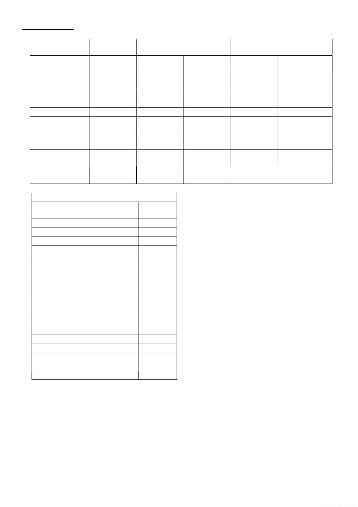
ACCESSORIES
SMV H
SMV HX / CO2
Sensor/Controller
Wired
Wired
Wired
Wired
AIM (Alarm
External Temp/RH
MEV Controller RH
Part
MVDC-MS / H
Name / Function
Temp/RH 496428 (240V) 496428 (240V) 496429 (240V) 496429 (240V)
CO2 (+RH)
0-10V
PIR - - 496438 (240V) 496438 (240V) 496438 (240V)
interface module)
battery powered
RS485 & RF868
Speed Switch
4 way
0-10V
496432 (240V) 496432 (240V) 496433 (240V) 496433 (240V) 496433 (240V)
- - - - 496441 (240V)
- - - - 496442 (Battery)
- - 496442 (240V) 496442 (240V) 496442 (240V)
- - 496621 (240V) 496621 (240V)
All units
Sensor/Controller Name
4-way analogue speed switch 496622
Timespan controller 563519
Air Quality Sensor 563506
Ambient response Humidity sensor 563550
Ecotronic Humidity sensor 563532
ThermoSwitch 563502
7 Day timer switch 563515
Visionex PIR 459623
3-pole Isolator switch 563518
Remote delay timer 457986
Isolator relay 442030
Normal/boost switch 455213
Normal/boost/purge switch 5108454
2-way switch with neon 459746
3 speed controller switch 563533
Normal / boost switch stainless 437320
Normal / boost switch with Neon 449060
LED Fault indicator 448356
0-10V
Number
SMV PLUS H
RS485
SMV PLUS HX / CO2
RS485
Wireless RF868
496429 (240V)
496431 (Battery)
496620 (240V)
496437 (Battery)
16
Page 17
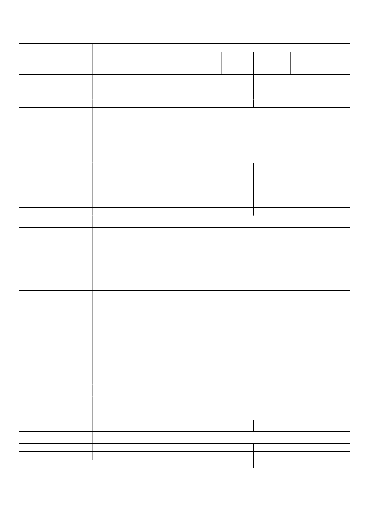
Product Fiche
of scope)
NRVU/UVU or BVU
Regenerative, None)
none)]
(@Max.Flow Rate)
Typology: (CTRL/ Typology)
extract air side;
energy efficiency of the unit
Disassembly Instructions)
20 Pa: (for Non
-
Ducted VUs)
(for Non
-
Ducted VUs)
Consumption: AEC (kWh/a)
(kWh/a)
Name: Vent-Axia
Model ID (Stock Ref.) 437634C 443298B 445655B 495360 495361
SEC Class B B B
SEC Value ('Average') -27.2 -27 -26.9
SEC Value ('Warm') -11.7 -11.5 -11.4
SEC Value ('Cold') -54.3 -54.1 -54.0
Label Required? (Yes/No=Out
Declared as: RVU or
Speed Drive Multi Speed
Type HRS (Recuperative,
Thermal Eff: [ (%), NA(if
Max. Flow Rate (m3/h) 338.8 400 505.1
Max. Power Input (W):
LWA: Sound Power Level dB) 46.4 50.7 52.2
Ref. Flow Rate (m3/s) 0.066 0.078 0.098
Ref. Pressure Diff. (Pa) 201 203 206
SPI [W/(m3/h)] 0.07 0.08 0.09
Control Factor & Control
Control Factor; CTRL 0.65
43 52 85
Yes
RVU/UVU
None
N/A
407849A
496186
495362 495363
Control Typology Local Demand Control
Declared: -Max Internal &
External Leakage Rates(%)
for BVUs or carry over (for
regenerative heat exchangers
only), Ext. Leakage Rates (%)
for Ducted UVUs;
Mixing Rate of Non-Ducted
BVUs not intended to be
equipped with one duct
connection on either supply or
Position and description of
visual filter warning for RVUs
intended for use with filters,
including text pointing out the
importance of regular filter
changes for performance and
For UVUs (Instructions Install
Regulated Supply/Extract
Grilles Façade)
Internet Address (for
Sensitivity p. Variation@+20/-
Air Tightness-ID/OD-(m3/h)
Annual Electricity
Annual Heating Saved: AHS
AHS: Average 28.3 28.3 28.3
AHS: Warm 12.8 12.8 12.8
AHS: Cold 55.4 55.4 55.4
0.4 0.5 0.6
<5% Internal, <5% External
N/A
N/A
In F&W
www.vent-axia.com
N/A
N/A
17
Page 18
Disposal
This product should not be disposed of with household waste. Please recycle where facilities exist. Check with your
local authority for recycling advice.
Applicable only to products installed and used in the United Kingdom. For details of guarantee outside the United Kingdom contact your local supplier.
Vent-Axia guarantees its products for two years from date of purchase against faulty material or workmanship. Motors are guaranteed for five years.
In the event of any part being found to be defective, the product will be repaired, or at the Company’s option replaced, without charge,
Has been installed and used in accordance with the instructions given with each unit.
Has not been connected to an unsuitable electricity supply. (The correct electricity supply voltage is shown on the product rating label attached to
the unit).
Has not been subjected to misuse, neglect or damage.
Has not been modified or repaired by any person not authorised by the company.
Please return the complete product, carriage paid to your original supplier or nearest Vent-Axia Centre, by post or personal visit. Please ensure that it is
adequately packed and accompanied by a letter clearly marked “Guarantee Claim” stating the nature of the fault and providing evidence of date and source of
The guarantee is offered to you as an extra benefit, and does not affect your legal rights
The Guarantee
provided that the product:
IF CLAIMING UNDER TERMS OF GUARANTEE
purchase.
Head Office: Fleming Way, Crawley, West Sussex, RH10 9YX. Tel: 01293 526062 Fax: 01293 551188
UK NATIONAL CALL CENTRE, Newton Road, Crawley, West Sussex, RH10 9JA
SALES ENQUIRIES: Tel: 0344 8560590 Fax: 01293 565169
TECHNICAL SUPPORT: Tel: 0344 8560594 Fax: 01293 532814
Web: www.vent-axia.com Email: [email protected]
Ventair Australia
Tel: +61 3 9775 0556
Fax: +61 39775 0775
Email: [email protected]
4 Capital Place, Carrum Downs, VIC 3201, Australia
As part of the policy of continuous product improvement Vent-Axia reserves the right to alter specifications without notice.
EU Authorised Representative: Vent-Axia Bedrijvenweg 17 7442 CX Nijverdal Nederland [email protected]
495584 D 0522
18
 Loading...