

Page 1
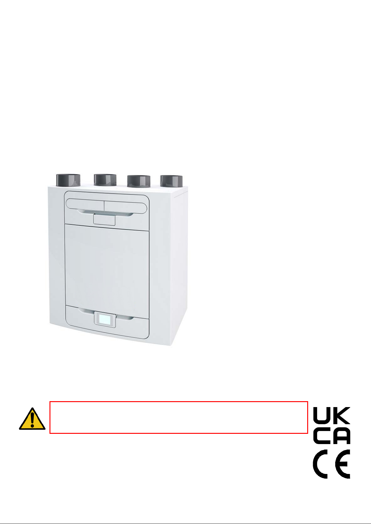
Advance
MVHR
Installation and User Guide
PLEASE REFER TO ACCOMPANYING DOCUMENTATION
FOR INFORMAT
PLEASE
PRODUCT
Stock Ref. N°
405215 Advance S
405216 Advance SX
476
476
808 Advance Sp LH
809 Advance Sp RH
PLEASE READ THESE INSTRUCTIONS CAREFULLY
BEFORE COMMENCING INSTALLATION O R OPERATION.
RETAIN THESE INSTRUCTIONS WITH THE
.
ION SPECIFIC TO YOUR UNIT.
Copyright © 2017 Vent-Axia. All rights reserved.
Page 2

Warnings and Safety Information
• Do not install this product in areas where the following may be present or occur:
• Excessive oil or a grease laden
atmosphere.
• Corrosive or flammable gases, liquids or
vapours.
• Subject to direct water spray from hoses.
• Ambient temperatures higher than 40°C
and lower than -20°C.
• Possible obstructions that may hinder
access to or removal of the unit.
• All wiring must be in accordance with the current IEE wiring regulations BS7671, or appropriate
standards of your country. Installation should be inspected and tested by a suitably qualified
person after completion.
• Ensure the mains supply (voltage, frequency and phase) complies with the rating label.
• The unit should be provided with a local double pole fused spur fitted with a 3A fuse having a
contact separation of at least 3mm. If a unit fitted with a preheater is being installed, a 13A fuse
should be used.
• These units must be earthed.
• Precautions must be taken to avoid the back-flow of gases into the building from the open flue of
gas or other fuel-burning appliances.
• This appliance is not intended for use by persons (including children) with reduced physical,
sensory or mental capabilities, or lack of experience and knowledge, unless they have been given
supervision or instruction concerning use of the appliance by a person responsible for their safety.
• Young children should be supervised to ensure that they do not play with the appliance.
• The installer is responsible for the installation and electrical connection of the sentinel system on
site. It is the responsibility of the installer to ensure that the equipment is safely and securely
installed and left only when mechanically and electrically safe.
• All regulations and requirements must be strictly followed to prevent hazards to life and property,
both during and after installation, and during any subsequent servicing and maintenance.
• The unit’s condensate drain must be connected to the building’s wastewater drainage system.
• Certain applications may require the installation of sound attenuation to achieve the sound levels
required.
• The unit must not be connected directly to a tumble drier.
• The supply and exhaust valves must be fully opened prior to commissioning.
• The intake air must be drawn from the exterior of the property.
• The unit should be allowed to stabilise during commissioning for a minimum period of 5 minutes
when changing between boost and normal speeds.
• Ensure that the unit’s external grilles are a minimum of 1500mm apart. The exhaust grille should
be located at least 600mm away from any flue outlet. The inlet grille should be located 2000mm
away from any flue outlet.
• This product and associated duct installation should be carried out in accordance with the
Domestic Ventilation Compliance Guide.
UK Building Regulations (Part F) Declaration of Conformance
The unit conforms to the 2010 Building Regulation (Part F - Means of Ventilation, F1(1), F(2)) requirem ents for fixed
systems for mechanical extract fans when installed in accordance with the instructions in this document and the
Domestic Ventilation Compliance Guide
2 MVHR Installation and User Guide 476930
Page 3

Operation and Monitoring 4
Product Description ....................................................................... 4
Controlling the unit......................................................................... 5
Touch screen display..................................................................... 5
Control via WiFi ............................................................................. 5
User controls ................................................................................. 6
Settings and Performance ............................................................. 7
Control Unit Screens Summary ................................................... 12
Control Unit Screens Summary ................................................... 13
Maintenance 14
Filter Maintenance ....................................................................... 14
Periodic Maintenance .................................................................. 15
Spares ......................................................................................... 16
Troubleshooting 17
Diagnosing a Problem ................................................................. 17
Installation 19
Overview ...................................................................................... 19
Wall Mounting the Unit ................................................................ 20
Floor Mounting the Unit ............................................................... 21
Floor Mounting the Unit (Alternate Method) ................................ 22
Vertical Discharge Condensate Installation ................................. 23
Attaching the ducting ................................................................... 24
Electrical Installation .................................................................... 25
Connect Switches and Sensors................................................... 26
Connect the Power Supply .......................................................... 28
Contents
Commissioning 29
Powering up the Unit ................................................................... 29
Overview ...................................................................................... 29
Control Unit Touch Screen Display ............................................. 29
Modifying Settings ....................................................................... 30
Commissioning Screens Summary ............................................. 31
Modifying Commissioning Settings ............................................. 33
Commissioning the Unit via USB................................................. 42
Accessories 43
Accessories ................................................................................. 43
WiFi Controller ............................................................................. 44
Input Switch Accessory ............................................................... 47
Switched Live Expansion PCB Accessory .................................. 49
Analogue Input PCB Accessory .................................................. 51
Wired Remote docking Kit Accessory ......................................... 53
Connecting an Opto-coupler ....................................................... 55
Remote LED Indicator and Lead Accessory ............................... 55
Flow Rate settings ....................................................................... 57
Frost Protection ........................................................................... 57
Summer Bypass Mode ................................................................ 58
Product Dimensions .................................................................... 59
Spares ......................................................................................... 60
Default settings ............................................................................ 61
Disposal ....................................................................................... 64
MVHR Installation and User Guide 476930 3
Page 4
Operation and Monitoring
Left Hand
Right hand
atmosphere
dwelling
atmosphere
atmosphere
Fit condensate drain
Fit drain cap
Fit drain cap
Fit condensate
Operation and Monitoring
Product Description
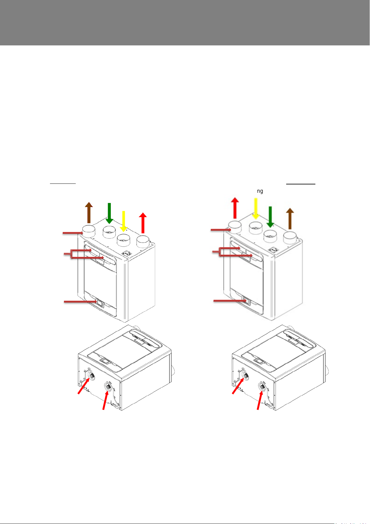
Mechanical Ventilation/Heat Recovery (MVHR). This heat recovery un it is designed for the energy
efficient ventilation of houses and s i milar dwellings, conforming to t he l atest requirements of the Building
Regulations document F 2010.
The unit is designed for continuous 2 4 hour extract ventilation of stale moist air from bathrooms, toilets,
utility rooms and kitchens. As the stale air is extracted, a heat exchang er within the unit transfers up to
93% of the extract air’s heat, into the supply air ent ering the bedrooms and lounge. This provides
significant energy recovery, reducing household heat costs, and providing the optimum comfort conditions.
In addition, some models will have features that maintain a constant airflow independent of the blocked
filters.
From
atmosphere
Extract from
To
Supply to
dwelling
Extract from
dwelling
From
Spigot
Filter drawers
Control panel
Supply to
dwelling
Spigot
Filter drawers
Control panel
To
drain with trap this
side.
Figure 1: MVHR with Left Hand and Right Hand spigot configuration.
Units with a preheater are preconfigur ed from the factory and the handing cannot be changed.
4 MVHR Installation and User Guide 476930
with trap this side.
Page 5
Operation and Monitoring
Controlling the unit
The unit can be controlled via t he Touch screen display, via WiFi, switche d i nputs, or via a third party building
control system.
Touch screen display
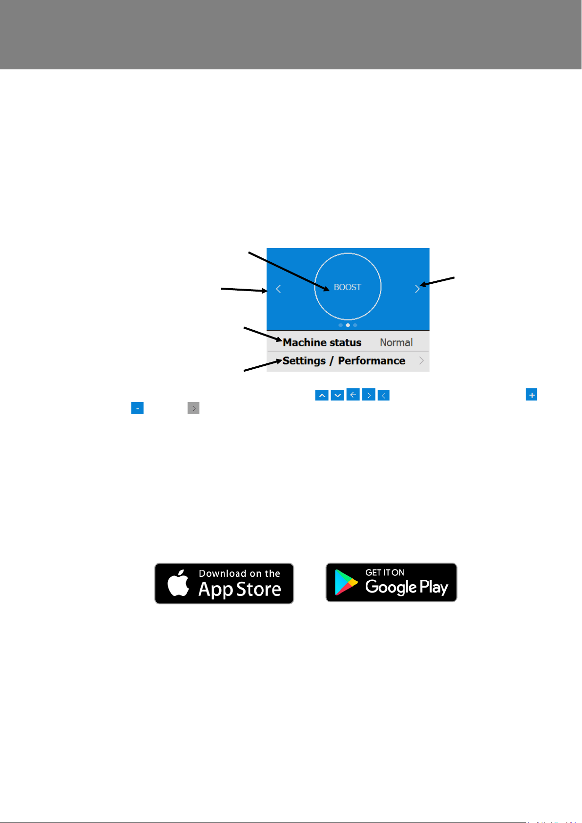
The touch screen display can be located on the front of the unit or connected to the unit via a remote docking kit.
The Control Unit provides the user interface for commissioning and monitoring purposes. The display is a resistive
touchscreen with LED backlight, which will turn off to automatically after 5 minutes to minimise power consumption.
To activate the backlight, touch the display.
User mode (Boost) button
Settings & Performance bar
Navigate through the functions by pressing the symbols, adjust settings using t he
buttons. A symbol indicates that there are further screens related to a menu option. Select the
option on the touchscreen to access the related screens.
Scroll Left
Status bar
Scroll Right
Control via WiFi
The MVHR WiFi control ler is a plug & play access ory that fits next to the control module. It allows the user instant
access to commissioning, configuration, direct monitoring and control of the MVHR unit, using a smart phone or
tablet with the app, available from the iTunes Store or on Google Play.
See page 43 for App address.
MVHR Installation and User Guide 476930 5
Page 6
Operation and Monitoring
User controls
User Menu Home Screen
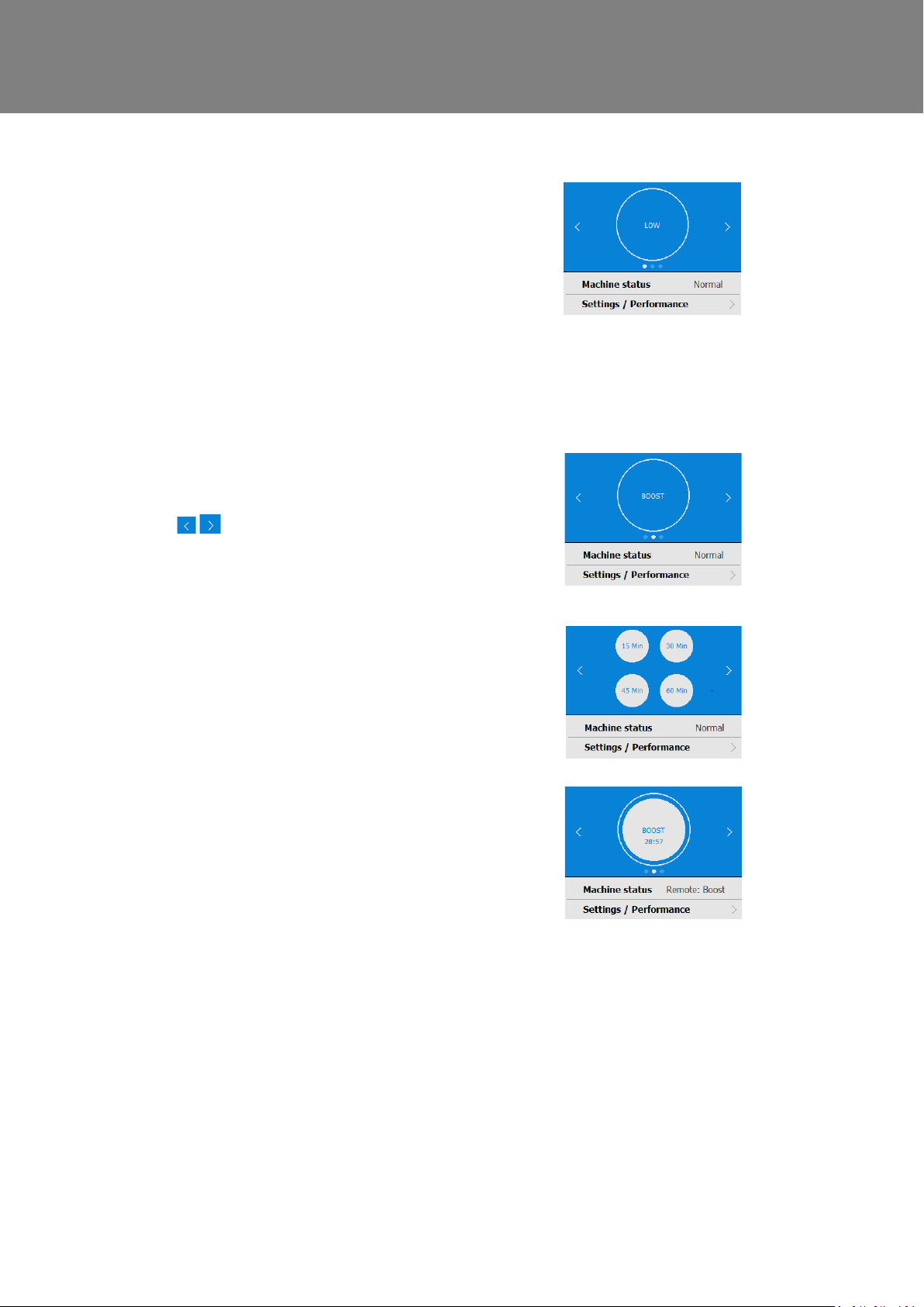
The user menu home screen, consists of a User
Mode (BOOST) button, a Machine stat us bar, and
a Settings / Performance bar.
The Machine status scrolls through Mode of
operation, Summer bypass status and Frost
protection status.
Press Settings / Performance to access these
menus.
User Mode
Scroll through the pre-defined user modes (factory
defaults are BOOST, LOW, and PURGE) using
the buttons either side of the User Mode
button. Select the required func tion by pressing the
centre button.
When a user mode is selected, selec t the duration
by pressing the required button from the four
options on the screen.
The button will appear white and the us er mode
will flash. A countdown clock will also appear
showing the time remaining for the selected User
Mode.
Pressing the User mode button agai n will cancel
the User Mode and the unit will default back to
Normal mode.
6 MVHR Installation and User Guide 476930
Page 7
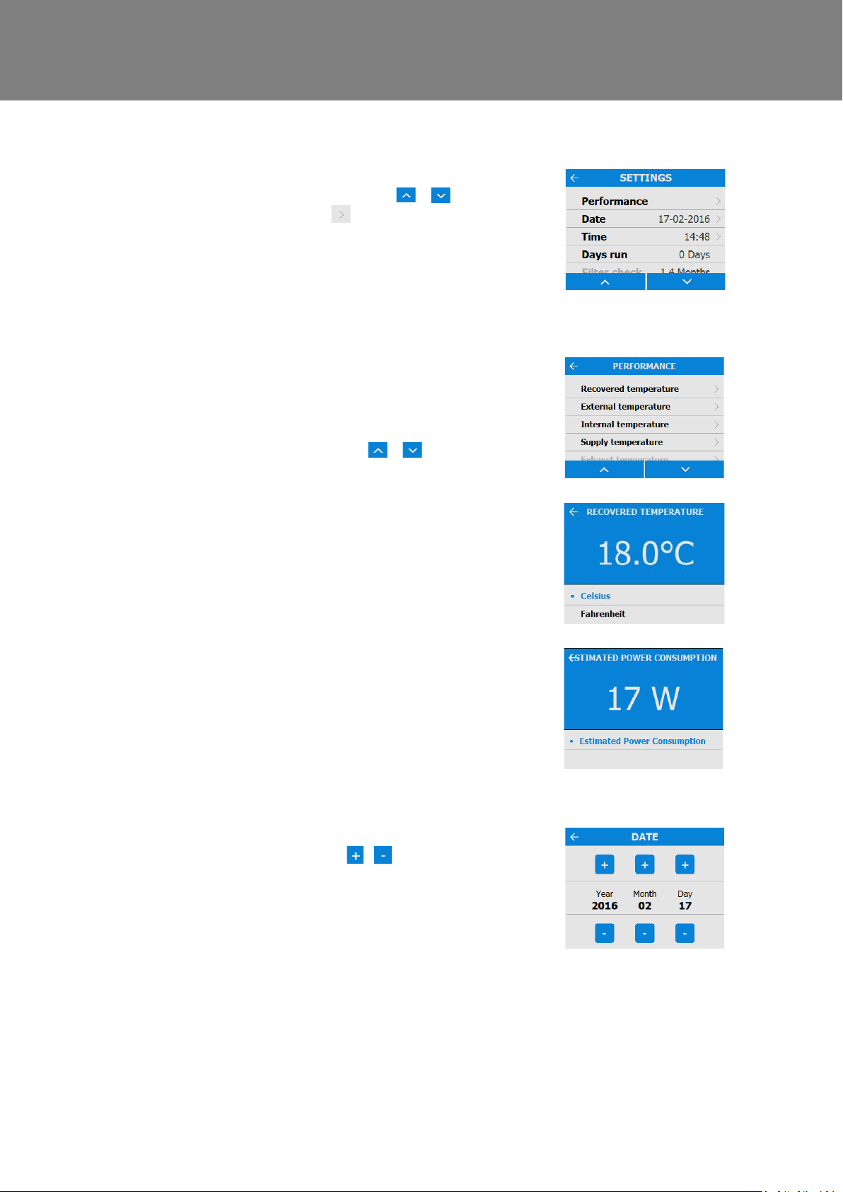
do not have editable parameters in this section.
Settings and Performance
Operation and Monitoring
Settings
Scroll through the settings using the &
buttons and select using where applicable to
access Language, Date, Time, Res et filter, Display
settings, Summer Bypass, Mode Sch eduling,
Service phone, Commissioner M enu & D iagnostics.
Days Run and Filter check are reporte d values and
Performance
The performance menu shows key performance
indicators such as recovered Temperature and
Estimated power consumption.
Scroll through the list using the & buttons
and select the required parameter.
Each performance temperature can be shown in
Celsius or Fahrenheit by pressing the required
temperature.
Date
Change the date using the / buttons on the
screen.
MVHR Installation and User Guide 476930 7
Page 8
Operation and Monitoring
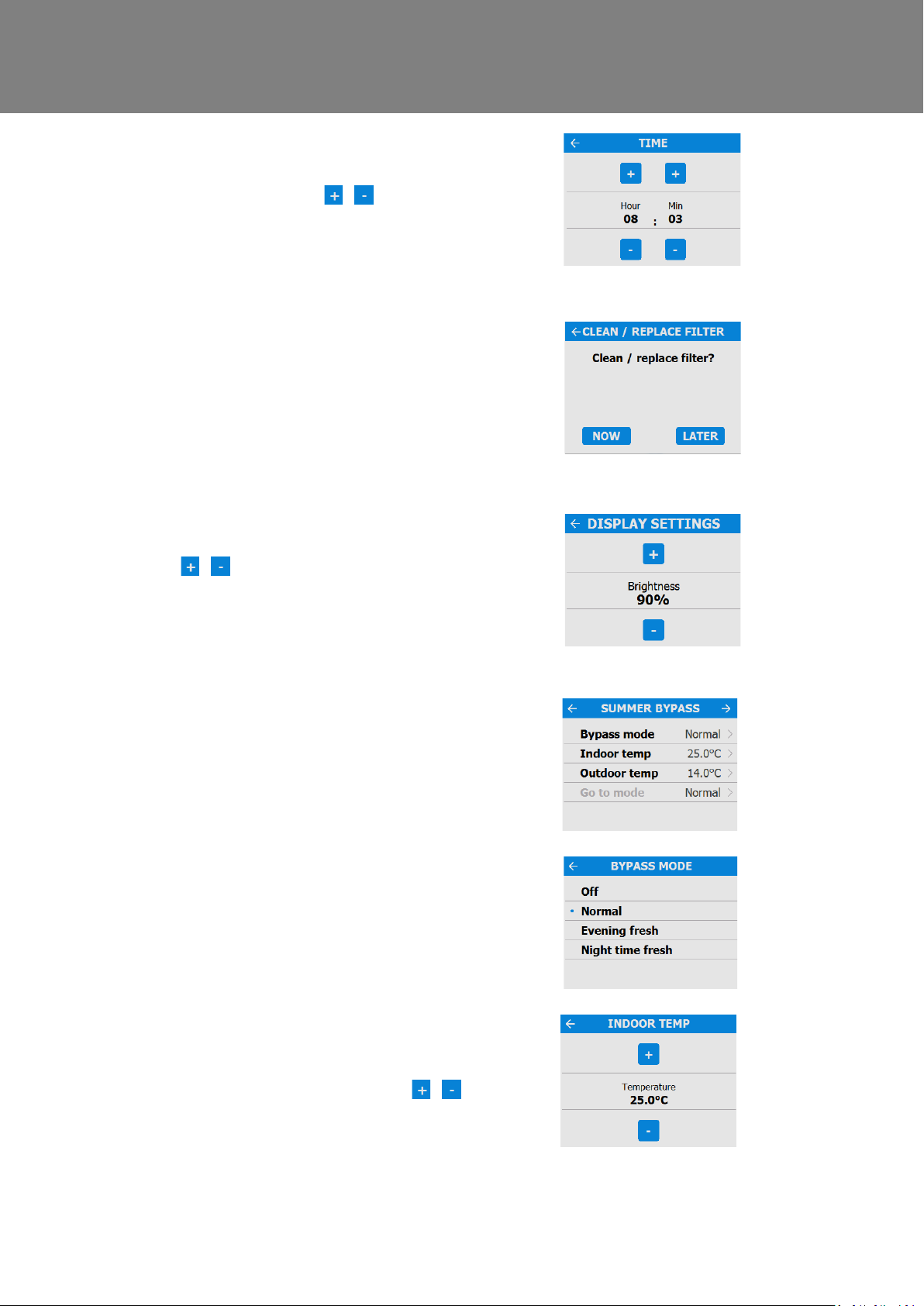
Time
Change the time using the / buttons on the
screen.
Note: The clock is 24 hour
Clean/Replace Filter
After maintenance or replacement of the filters, the
filter timer can be reset by press i ng NOW.
Press LATER to return to the Settings Menu.
Display Settings
Change the brightness of the touch screen using
the / buttons.
Summer Bypass
See page 9 for a full description of the S ummer
Bypass modes and functions
Select the required bypass mode.
The indoor temperature setting is the maximum
desired room temperature. This s hould be set to 3°
above the central heating temperature.
Change the indoor temperature usin g the /
buttons on the screen.
8 MVHR Installation and User Guide 476930
Page 9
Operation and Monitoring
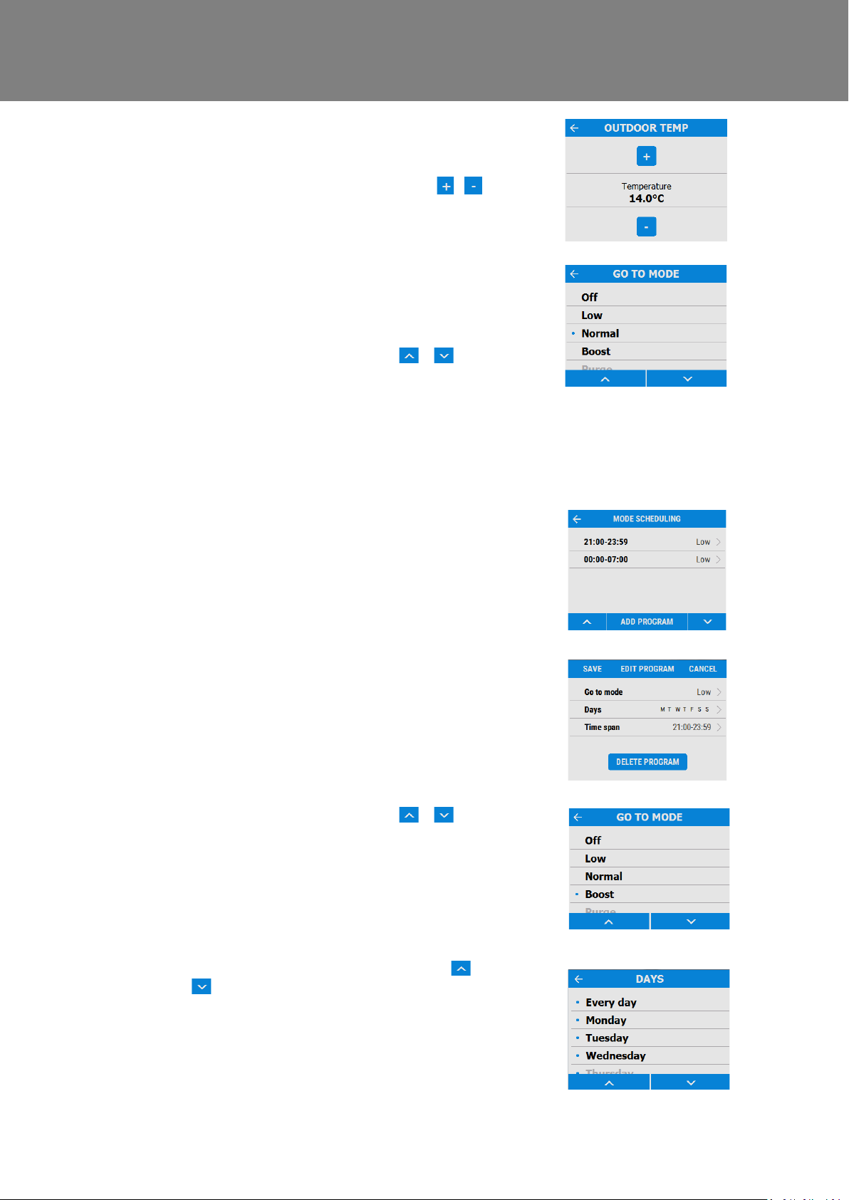
The outdoor temperature is the minimum air
temperature that the bypass will permit. This is to
prevent cold draughts.
Change the outdoor temperature using the /
buttons on the screen.
This is the mode the bypass will switch to when
activated.
The suggested Mode for Evening fresh and Night
time fresh setting is Boost.
Scroll through the settings using the &
buttons and select the Go To mode.
Note: Number of available modes may differ from
image shown depending on bypass s etting and the
modes set in the commissioning proces s.
Mode Scheduling
Use a schedule to set a Mode (Airflo w setting) for a
fixed, repeated period. For exampl e, set Boost
Mode every morning between 7:00am and 8:00am
while cooking breakfast.
Select the Schedule to view the settings
Scroll through the settings using the &
buttons and select the Go To mode for each
Schedule.
Scroll through the days of the week us ing the &
the Schedule program.
buttons and select each day to be included in
MVHR Installation and User Guide 476930 9
Page 10
Operation and Monitoring
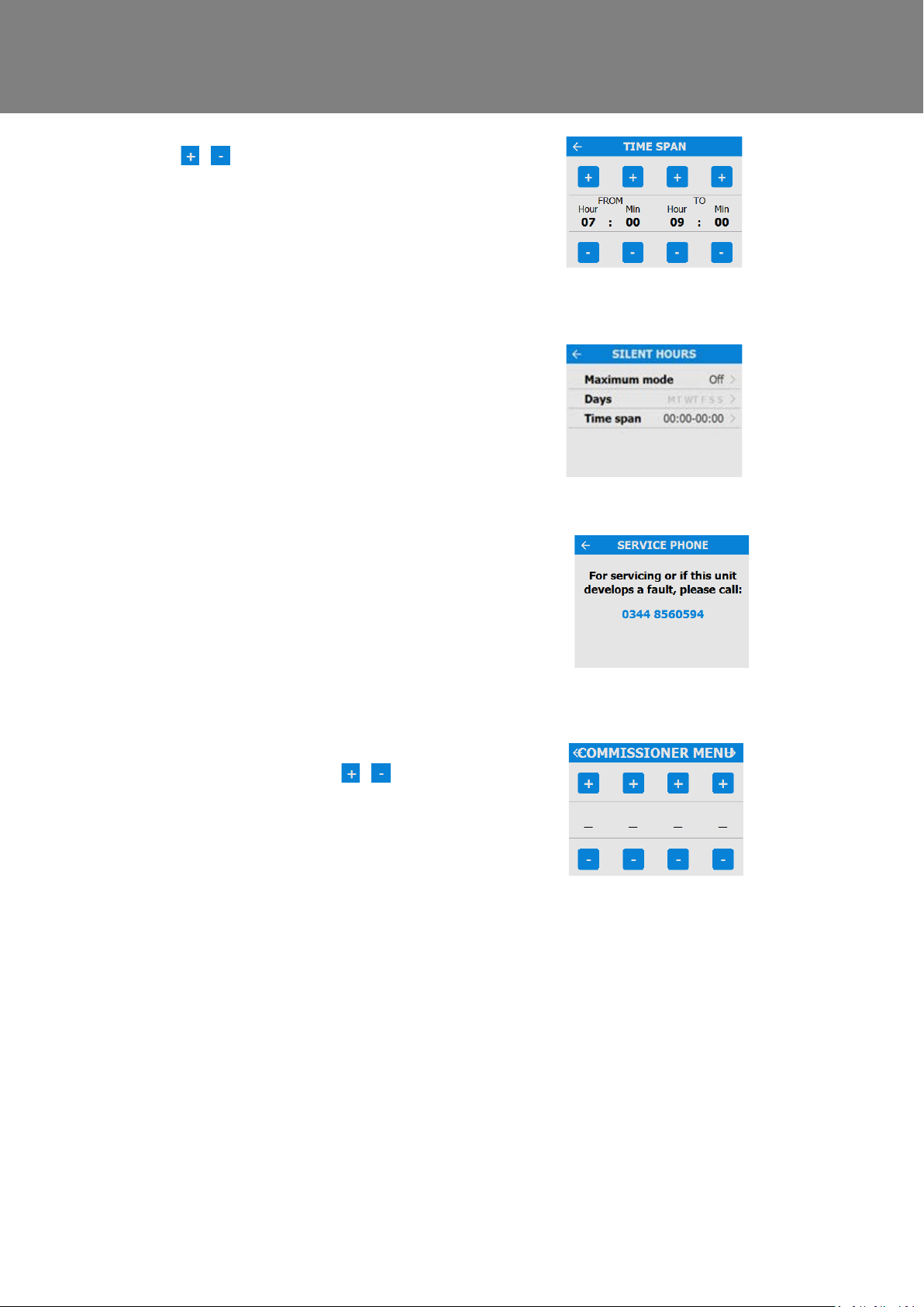
Adjust the start and finish times f or each day using
the / buttons.
Silent Hours
Silent Hours mode is useful to impose a speed/flow
restriction on the unit to minimise unwanted noise
during the night.
If Silent hours are enabled, the unit will not speed
up above the set Maximum Mode. Silent Hours can
be set to reoccur on specific da ys and times.
Service Phone
The service phone number can be ent ered by the
installer and should be used if the unit displays a
fault code, or to arrange routine servi cing for the
unit.
Commissioning Menu
Enter the lock code using the / but tons to
access the Commissioner Menu.
Note: the lock code is set by the installer and
settings beyond this point should o nly be accessed
and modified by a qualified install er .
10 MVHR Installation and User Guide 476930
Page 11
Operation and Monitoring
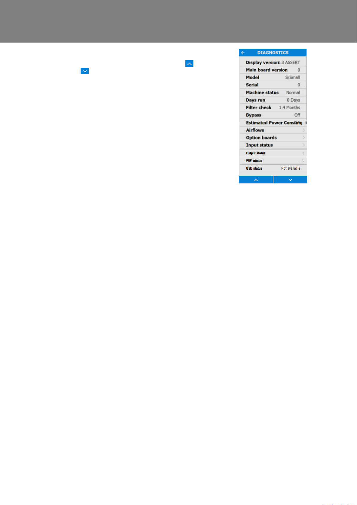
Diagnostics
Scroll through the Diagnostics l ist using the &
buttons to access the following infor mation.
Machine Status, Days Run, Filter Check, Bypass,
Energy Consumption, Air flows, Opti on boards.
Input status, Output Status, WiFi Status, WiFi
signal.
Note: Optional upgrades may be neces sary to view
all information.
MVHR Installation and User Guide 476930 11
Page 12
Operation and Monitoring
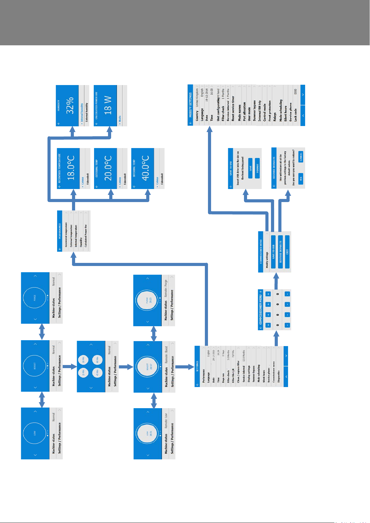
Control Unit Screens Summary
The following Control Unit screens are available for daily operati on and monitoring of the unit. Colour and visual
appearance may be different to the below depending on model version and region.
Refer to next page for an
expanded version of
available screens in this
section.
12 MVHR Installation and User Guide 476930
Page 13
Operation and Monitoring
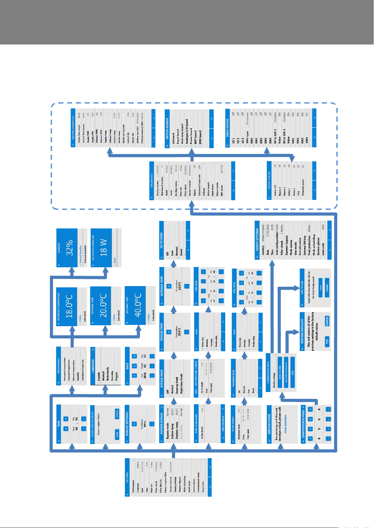
Control Unit Screens Summary
The following Control Unit screens are available in the Settings / P erformance section. Colour, vis ual appearance, and
some features may be different to the below depending on model version and region.
MVHR Installation and User Guide 476930 13
Page 14
Maintenance
Maintenance
Filter Maintenance
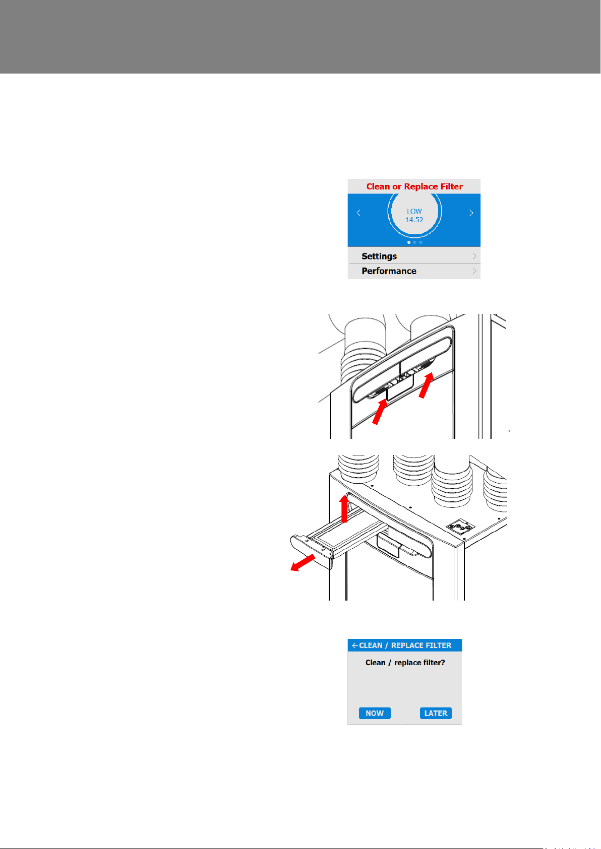
Heat recovery units require regul ar maintenance.
This unit has been designed to facilitate access to enable maintenance to be carried out easily.
When the unit displays “Clean or repl ace
filters”. This is a reminder to ensure t hat
the filters are not so dirty that they are
blocking the airflow or allowing di r t to pass
through. The rate at which the filters
become dirty will vary hugely depending
on the environment and the activity within
the property.
See page 61 for a list of spare filters.
1. Open the filter drawers by pressing the
finger plate upwards and sliding t he drawer
out.
2. Lift each filter out and clean gently by
tapping or carefully using a vacuum
cleaner if necessary.
3. Replace the filters
4. Close the filter drawers, ensuri ng the
latches have clicked back into the locked
position.
5. After maintenance of the filters, the filter
timer can be reset by going to
Settings/Performance,
Clean/Replace filter.
14 MVHR Installation and User Guide 476930
Page 15
Fan Filters
Periodic Maintenance
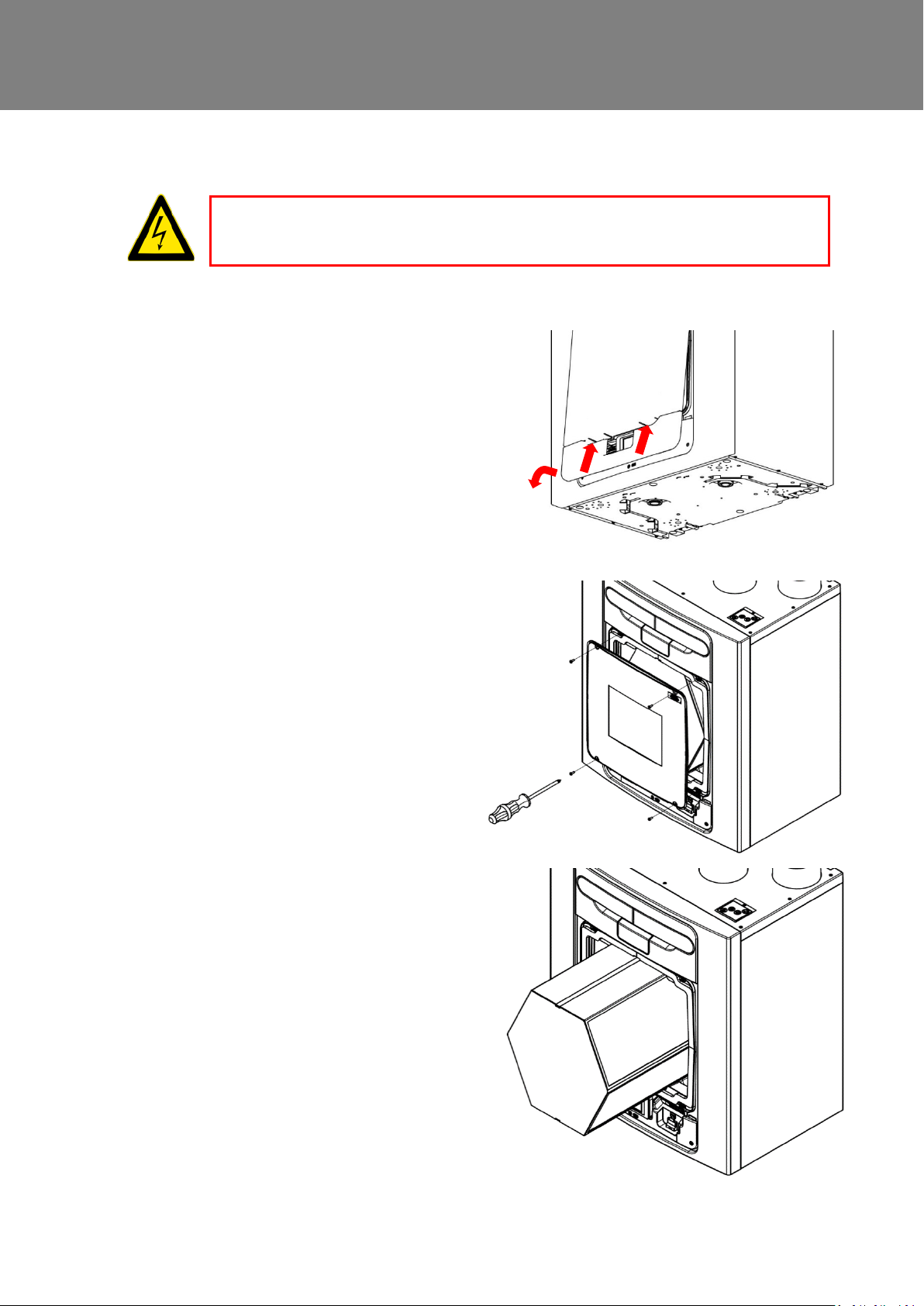
THE FAN AND ANCILLARY CONTROL EQUIPMENT MUST BE ISOLATED FROM THE POWER SUPPLY
DURING MAINTENANCE.
Maintenance
WARNING
Check fan filters as described on the
previous page.
Heat Exchanger Cell
Step 1: Remove the outer cover by
pressing the tabs either side of t he c ontrol
module and lifting the cover outwards from
the bottom edge.
Step 2: Remove the inner door by undoing
the 4 retaining screws.
Step 3: Slide the heat exchanger out from
the unit.
Step 4: Wash the outer cover and heat
exchanger in warm water using a mild
detergent (such as Milton Fluid) and dry
thoroughly.
NOTE: Keep water away from all
electrical components and wiring within
the unit.
Motors
Inspect the motors for build-up of dus t and
dirt on the impeller blades, which co ul d
cause imbalance and increased noise
levels. Vacuum or clean if necessar y.
Condensate Drain
Check the condensate drain tube is secure
and clear of debris. Clean if necessary.
Ensure the trap is fully charged with water.
Fastenings
Check that all unit and wall-mount
fastenings are sufficiently tig ht and have
not become loose. Re-tighten if necess ary.
MVHR Installation and User Guide 476930 15
Page 16

Maintenance
Spares
The following spare parts may be ordered from Vent-Axia:
Part No Description
472663 Main Power Board
472665 Control Module
472667 Filters G3, 2 per pack
472669 Filters M5, 1 per pack
472671 Filters F7, 1 per pack
472673 Motor Scroll Assembly
472675 Summer Bypass Motor Assembly
472685 Temperature/Humidity Sensor T1 (Right)
472679 Temperature Sensor T2 (Left)
472687 Temperature/Humidity Sensor T3 (Left)
472683 Temperature Sensor T4 (Right)
478335 Constant Volume + Clean Filter Pressure Sensors PCBA
Table 3: Spare parts
16 MVHR Installation and User Guide 476930
Page 17
Troubleshooting
Code
Problem
Diagnosing a Problem
In the event of a problem, always troubl es hoot the unit according to:
Warning code displayed on the control unit.
A warning code is advisory and will not i m mediately stop the function of t he unit.
Fault code displayed on the Control Unit.
Fault LED if connected.
If no indications are displayed, then troubleshoot problem according to the fault symptom as described in
the following tables.
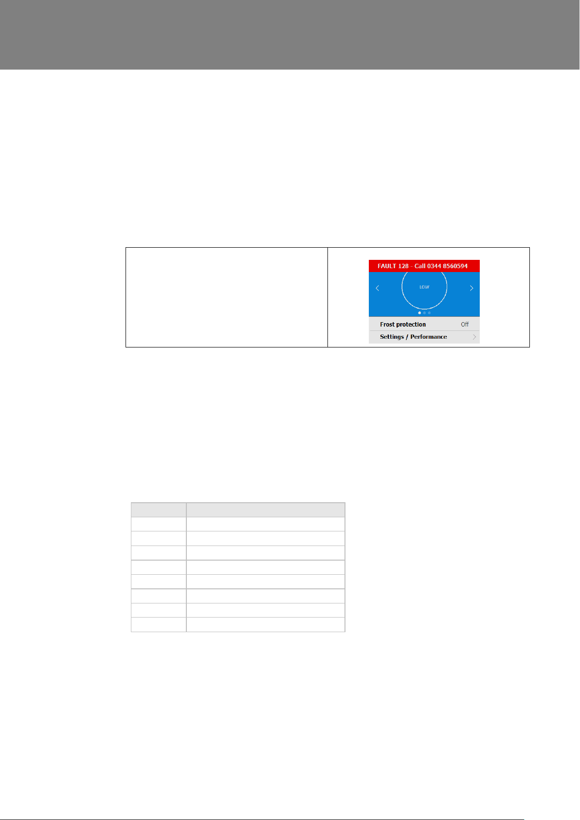
Service/Fault Code Screens
Troubleshooting
The Fault Code notification is displayed, when a
fault has occurred. Take note of the faul t code
when reporting a fault.
For assistance contact the servic e pr ovider and quote the fault code number and the product serial
number which can be found behind the front cover.
Note that the fault code is not displayed until the fault has been present f or 3 minutes.
The following fault codes numbers may be displayed.
Code numbers are added together if more than one fault is detected.
For example: Code 03 indicates that both left and right fans are not running.
01 Left Fan Fault
02 Right fan Fault
04 Left Thermistor Fault
08 Right Thermistor Fault
16 Left Centre Thermistor Fault
32 Right Centre Thermistor Fault
64 Left Centre Temp/Humidity Sensor Fault
128 Right Centre Temp/Humidity Sensor Fault
Table 4: Fault Codes
MVHR Installation and User Guide 476930 17
Page 18
Troubleshooting
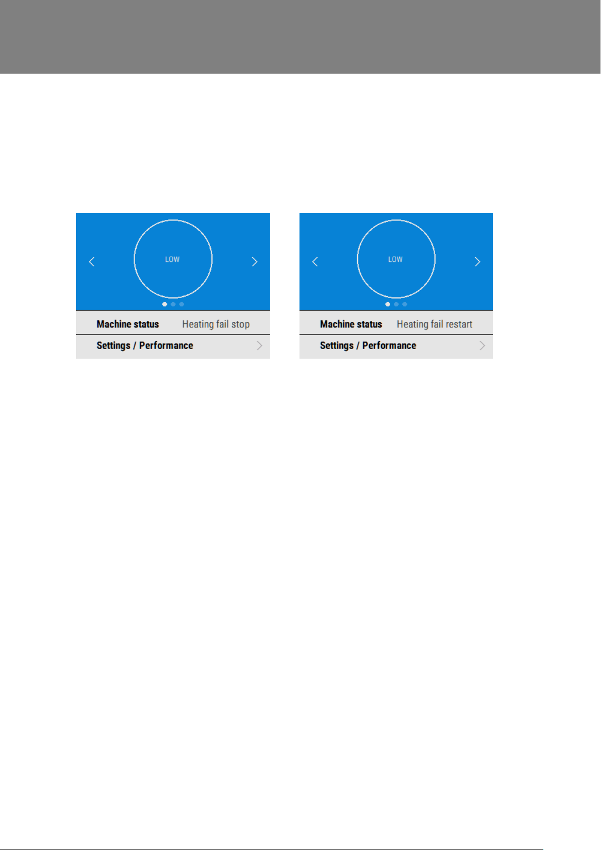
Room Too Cold Screen
The Room Too Cold screen displays the status of the fan. If the heating system i n the building fails or is switched
off and the internal temperature drops below 5°C, the unit will stop runnin g so as to not bring cold air into an
already cold house. The unit will start up every hour and will run for a short tim e to measure the temperature of
the property. When the temperature rises, e.g. the heating system is switched back on, the unit will restart and
continue normal operation.
Bottom line of display may be (Fan Off, Fan Restarting).
18 MVHR Installation and User Guide 476930
Page 19
Installation
Installation
Overview
Before installation of the unit
We advise installers to fix all mains and sensor wiring along with any inter nal accessories prior to fixing
the MVHR unit in position, leaving approximately 500mm tails to allow for internal routing.
Inspect the Unit
When taking delivery of the unit, check the items delivered against the enc l os ed delivery note. Inspect the unit for
damage in transit. If in doubt, contact Customer Services. Each box cont ai ns a heat recovery unit, a wall brack et
and accessory pack containing miscellaneous fixings and product documentation.
Unit Installation
Installation should be carried out by a suitably qualified and competent person.
If the unit is wall mounted, the wall sh ould have sufficient strength to support the unit
The unit may also be floor mounted, either directly to the floor or using standard kitchen cabinet feet (not supplied).
Ensure that the unit is mounted upright.
Do not use this unit as a support for any other equipment.
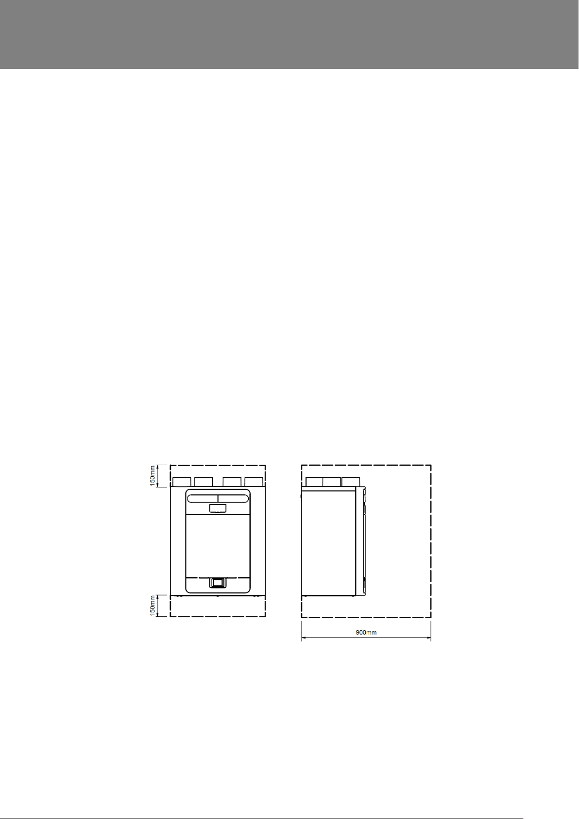
Service Void
Clearance must be left around the unit to allow for cleaning and servicing, the dimensions below are the minim um requirements. The condensate drain trap used will dictate the necessary clearance below the unit which may be larger than the minimums.
Select Unit Configuration
The unit is configurable as either Left or Right Handed (Default), see page 4 for the spigot configuratio n. Use the
left hand condensate drain for the Left Hand configuration, the right hand dr ain for the Right Hand configuration. If
the unit is fitted with a preheater, the configuration is factory set and c annot be altered.
MVHR Installation and User Guide 476930 19
Page 20
Installation
Top of unit
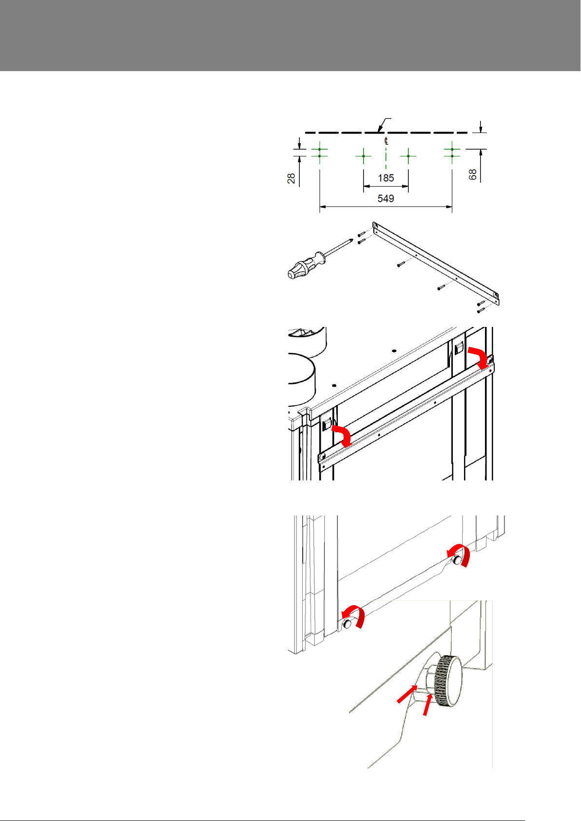
Wall Mounting the Unit
Step 1: Mark the wall bracket position
using the dimensions shown. Note t he
position of the top of the unit in relation
to the wall bracket. Ensure the br ac ket
position is horizontal.
Step 2: Attach the wall bracket to the
wall using appropriate fixings.
Step 3: Lift the unit and locate the two
hooks on the rear onto the wall bracket.
Step 4: Make sure the unit is level or
leaning slightly backwards; this is to
ensure the condensate drain functio ns
correctly.
The mounting feet at the base of t he uni t
are adjustable. From the factory, the
mounting feet are set to compensate for
the standoff caused by the mounting
bracket. Adjust the feet in or out to level
the unit as necessary.
20 MVHR Installation and User Guide 476930
If mounting on uneven walls, the
spacers (A) may need to be removed
before the feet can be screwed further
into the unit.
Lock the mounting feet into their final
position using the M6 nuts (B).
Page 21
Base fixing
holes 11 x 4
7
Top of unit
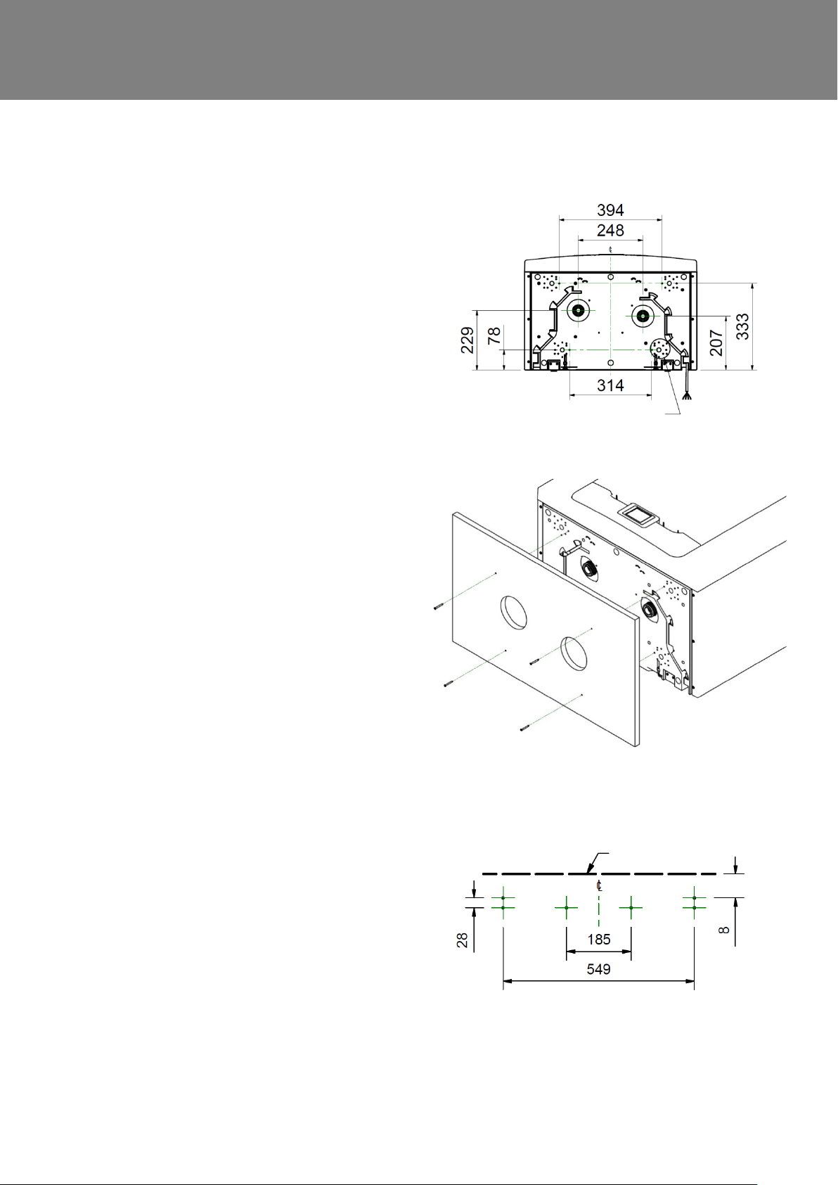
Floor Mounting the Unit
Step 1: The unit has 44 x 12mm deep
fixing holes on the underside suitable
for a No.6 screw. Pre drill a board using
the dimensions shown, and cut 2 x
105mm minimum diameter holes for t he
condensate drain access.
Step 2: Mount the board to the
underside of the unit using appropriate
fixings.
Installation
Note: Ensure any other cabling
requirements (e.g. sensor, control
cables etc) are routed through the two
cable channels as required prior to
attaching the board.
The board may then be attached to
joists, flooring, or equivalent.
Vent-Axia recommend that where
possible, the wall bracket is used in
conjunction with any floor mount
solution to prevent the unit from t ippi ng.
Step 3: Mark the wall bracket position
using the dimensions shown. Note the
position of the top of the unit in relation
to the wall bracket. Ensure the bracket
position is parallel to the floor.
Step 4: Attach the wall bracket to the
wall or batten using appropriate fixings.
(As shown on page 19)
Step 5: Lift the unit and locate the two
hooks on the rear onto the wall bracket
prior to fixing the unit to the floor. (As
shown on page 19)
MVHR Installation and User Guide 476930 21
Page 22
Installation
7
Base fixing holes
11 x 4
Top of unit
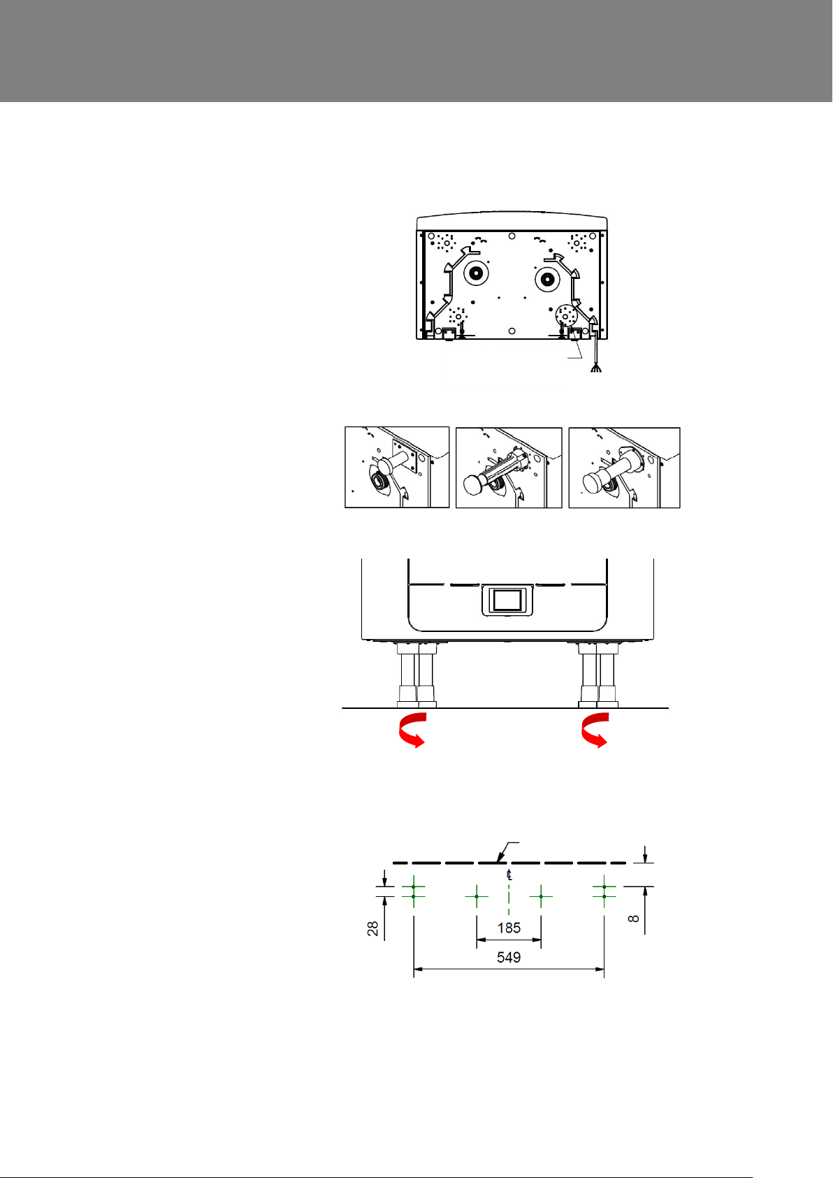
Floor Mounting the Unit (Alternate Method)
Step 1: The unit has 44 x 12mm deep
fixing holes on the underside suitable
for a No.6 screw. The holes are
configured to allow fitment of most
standard kitchen foot types (not
supplied).
Step 2: Mount your chosen foot type to
the underside of the unit using
appropriate fixings.
Step 3: Adjust your chosen foot type to
ensure the base of the unit is horizontal
in both axis.
It is recommended that where possible,
the wall bracket is used in conjunction
with any floor mount solution to prevent
the unit from tipping.
Step 4: Mark the wall bracket position
using the dimensions shown. Note t he
position of the top of the unit in relation
to the wall bracket. Ensure the bracket
position is parallel to the floor.
Step 5: Attach the wall bracket to the
wall or batten using appropriate fixi ngs.
(As shown on page 19)
Step 6: Lift the unit and locate the two
hooks on the rear onto the wall bracket
prior to fixing the unit to the floor. (As
shown on page 19)
22 MVHR Installation and User Guide 476930
Page 23
Vertical Discharge Condensate Installation
Note
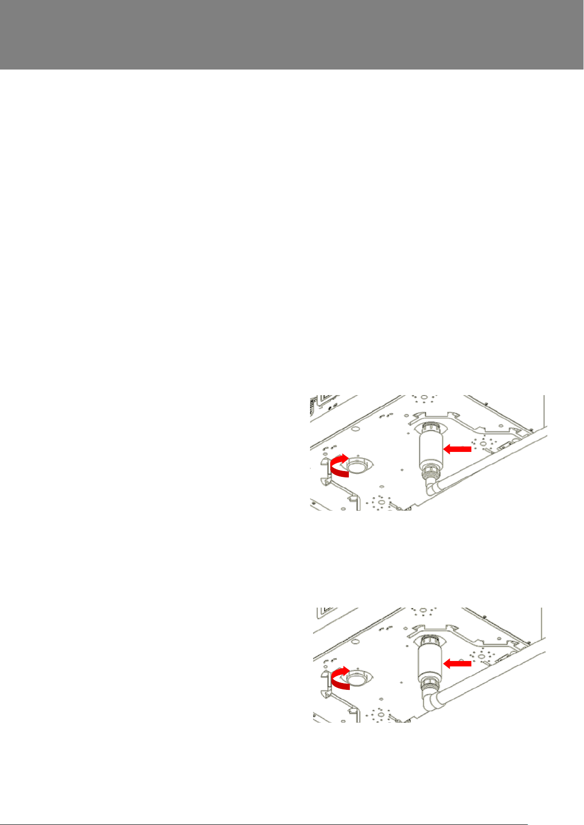
A trap must be fitted between the condensate drain of the unit and the rest of th e waste system.
A waterless trap is recommended, as they are not susceptible to drying out during warmer periods
when no condensate is formed. An example of a suitable waterless trap i s t he Osma HepVo
waterless trap.
If a conventional trap is used, a t rap with a minimum water seal of 60mm must be selected.
The condensate outlet is compatible with standard 22 mm plastic solvent weld fittings and 32mm threaded
waste pipe fittings. Wastepipes must have a 3 degree minimum angle to allow the water to drain away from
the unit naturally.
In areas where freezing weather cond i tions occur, outlet pipes must be insulated to avoid blockage by ice,
which may cause damage to the unit and surroundings.
This guide shows a Right Hand configuration for illustration.
Installation
If the unit is configured as Left Hand, then the condensate drain should be installed on the left with
the blanking cap on the right.
22mm waste pipe
Fit a waterless trap, or a conventional trap
with a water seal of at least 60mm, close
to the unit.
An adaptor can be used to adapt from
32mm to 22mm connections.
Fit the blanking cap supplied wit h the unit
to the appropriate side, depending on the
handing, see page 4. Ensure the sealing
gasket is fitted inside the blanking cap.
32mm waste pipe (recommended)
Fit a waterless trap, or a conventional trap
with a water seal of at least 60mm, close to
the unit.
Fit the blanking cap supplied wit h the unit
to the appropriate side of the unit,
depending on the handing of the unit, see
page 4. Ensure the sealing gasket is fitted
inside the blanking cap.
MVHR Installation and User Guide 476930 23
Page 24
Installation
Compliance Guide
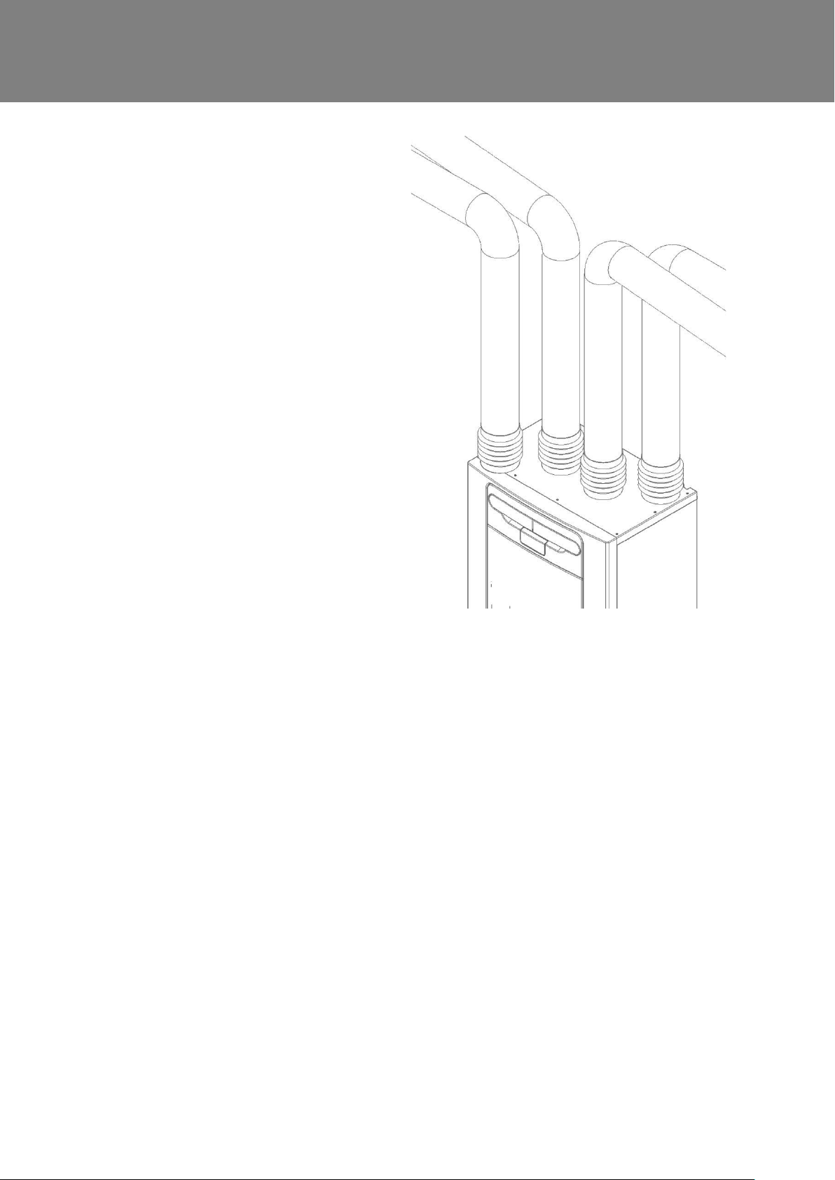
Attach the Ducting
1. Always use a short piece of insulated
flexible duct maximum 150 mm long,
extended to its full length when
connecting to ductwork.
2. Securely connect the ducting to the
spigots using worm-drive clips or suitable
plastic ties.
3. Insulate any ducting passing through an
unheated space to prevent any heat
losses or surface condensation.
4. Insulate all ducting to and from outside
vents.
All ducting must be installed in
accordance with the Domestic Ventilat ion
24 MVHR Installation and User Guide 476930
Page 25
Electrical Installation
THE ENSURE THE ELECTRICAL SUPPLY AND CONTROLS ARE ISOLATED FROM THE POWER
SUPPLY BEFORE REMOVING ACCESS COVERS
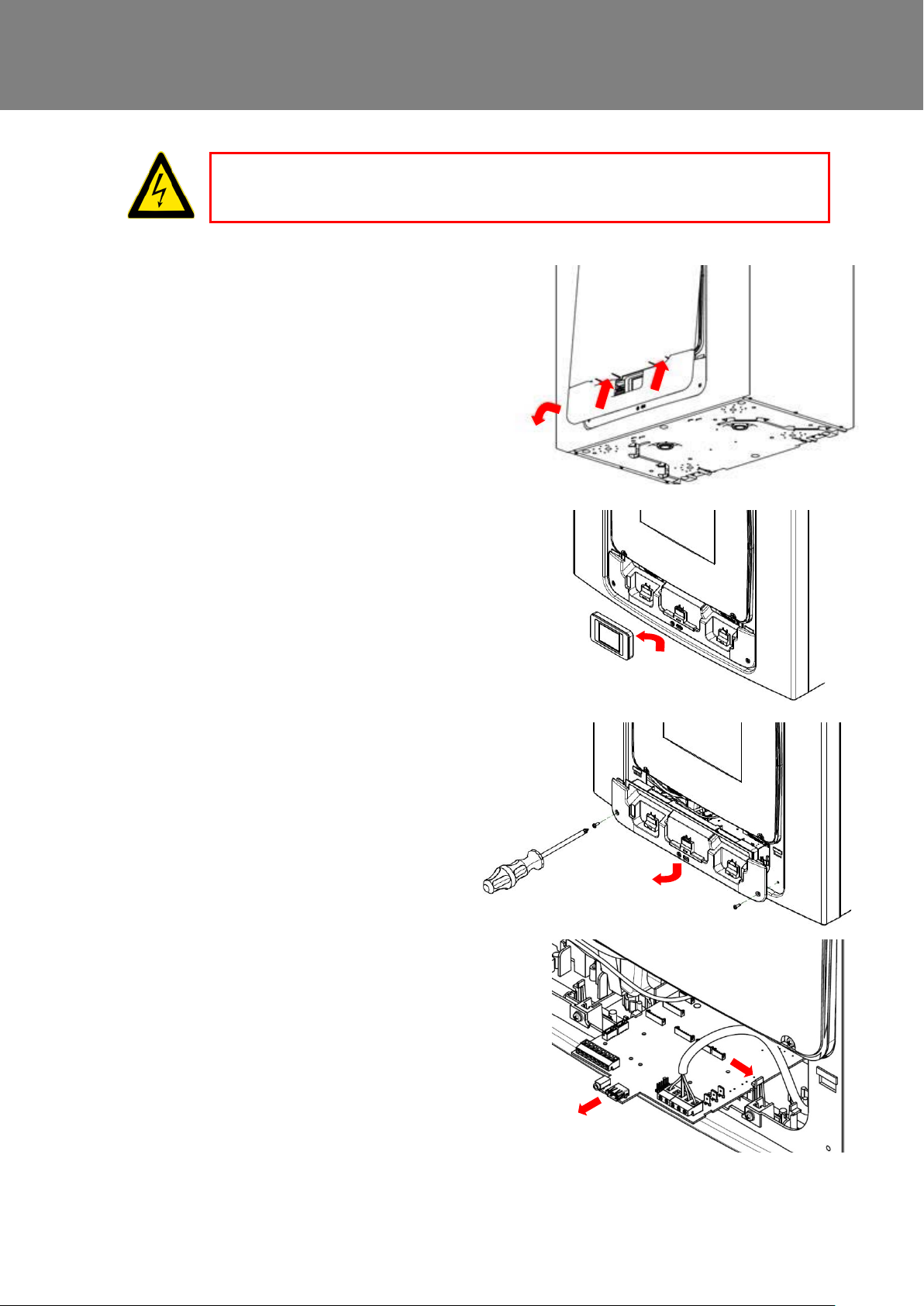
Step 1: Remove the outer cover by
pressing the tabs either side of t he c ontrol
module and lifting the cover outwards from
the bottom edge.
Installation
WARNING
Step 2: Remove the control module by
sliding it upwards and away from the uni t.
Step 3: Remove the two screws on either
side of the access panel. Lift the pane l
outwards from the bottom edge to rem ov e.
Note: The access panel is tethered on the
left hand side.
Note: All printed circuit boards are ESD
sensitive. Always ensure the correct ESD
protection is used (e.g. conductive wrist
straps and anti-static mats.)
Step 4: Push the locking tab away from
the printed circuit board and slide it
outwards to access the terminals
Note: The printed circuit board will relock
after 60mm
MVHR Installation and User Guide 476930 25
Page 26
Installation
Connect Switches and Sensors
The unit can be switched to boost by applying 240V to the LS input .
Note: Alternative switches and inputs can be achieved by adding optional input accessories to the
printed circuit board. See Accessories on page 42 for further details.
For good EMC engineering practice, any sensor, switched live or Vo lt free cables should not be
installed within 50mm of other cable or on the same metal cable tray as o t her cables.
Connect any switches or sensors r equired to control the unit by connecting to the terminal connectors at
the bottom of the control unit as shown on the next page in Table 1. If necessary contact your distributor
regarding the wiring and fixing of accessories and sensors.
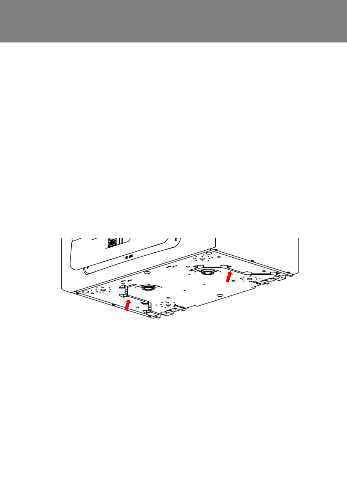
When fitting external controls, all cables should be routed through t he two cable channels on the underside
of the unit shown below.
Figure 4: cable channels
26 MVHR Installation and User Guide 476930
Page 27
Installation
May also be used for a connection to a BMS or similar.
Other means of connecting the
unit may be used if they meet
the local wiring regulations.
SEE NOTES ON THE NEXT
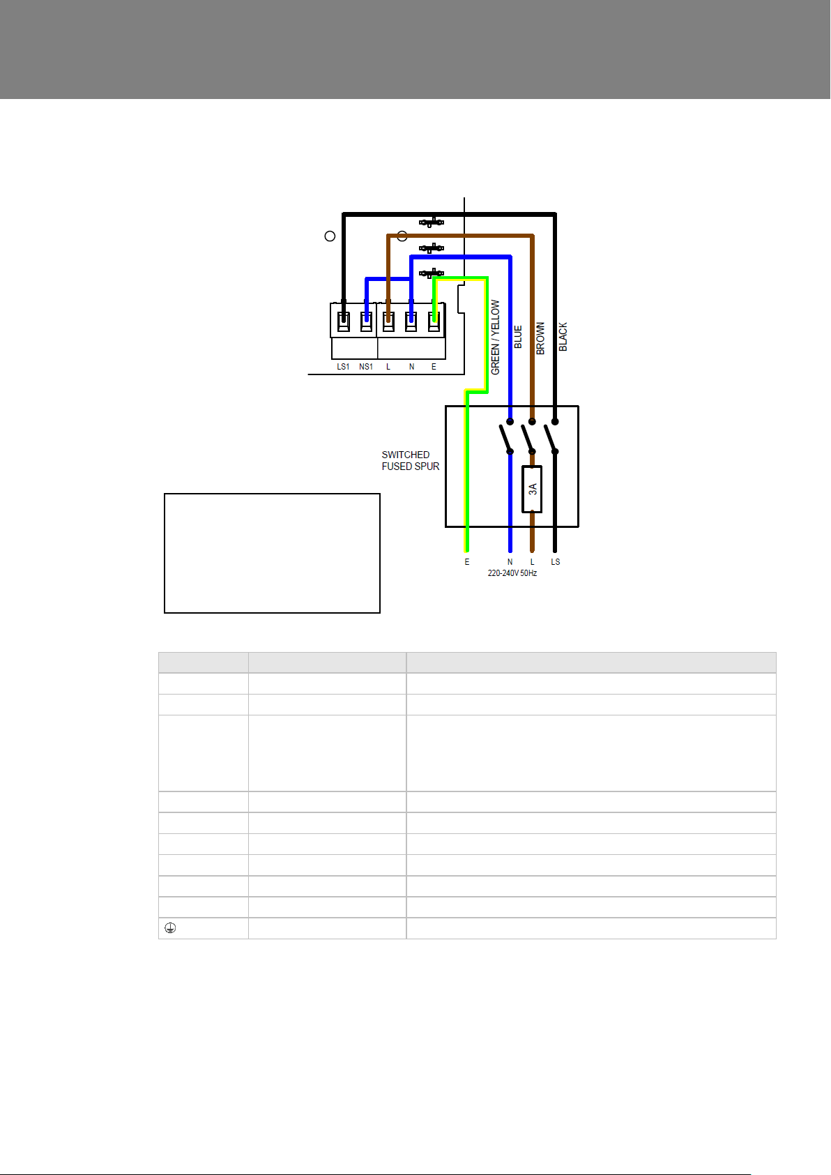
Terminal No. Name Description
REMOTE Remote Terminals for connecting a remote external to the unit.
SWI Switch 1 Volt-free contact for sensor input between + and - terminals
LED Red Light Emitting Diode
DIAG Diagnostic Diagnosti c port
USB USB C om missioning port.
LS1 Switched Live 220-240 V AC, 50 Hz input
NS1 Switched Neutral 220-240 V AC, 50 Hz input
L Mains Live 220-240 V AC, 50 Hz input
N Mains Neutral 220-240 V AC, 50 Hz input
EARTH Mains Earth Earth connector
PAGE
Output
A LED driving signal output bet wee n the + and – terminals that
enables remote indication of a unit fault. See the Control Panel
for fault code (see Service/Fault Code Screens on page 17
).
Table 1: Terminal Connections
MVHR Installation and User Guide 476930 27
Page 28
Installation
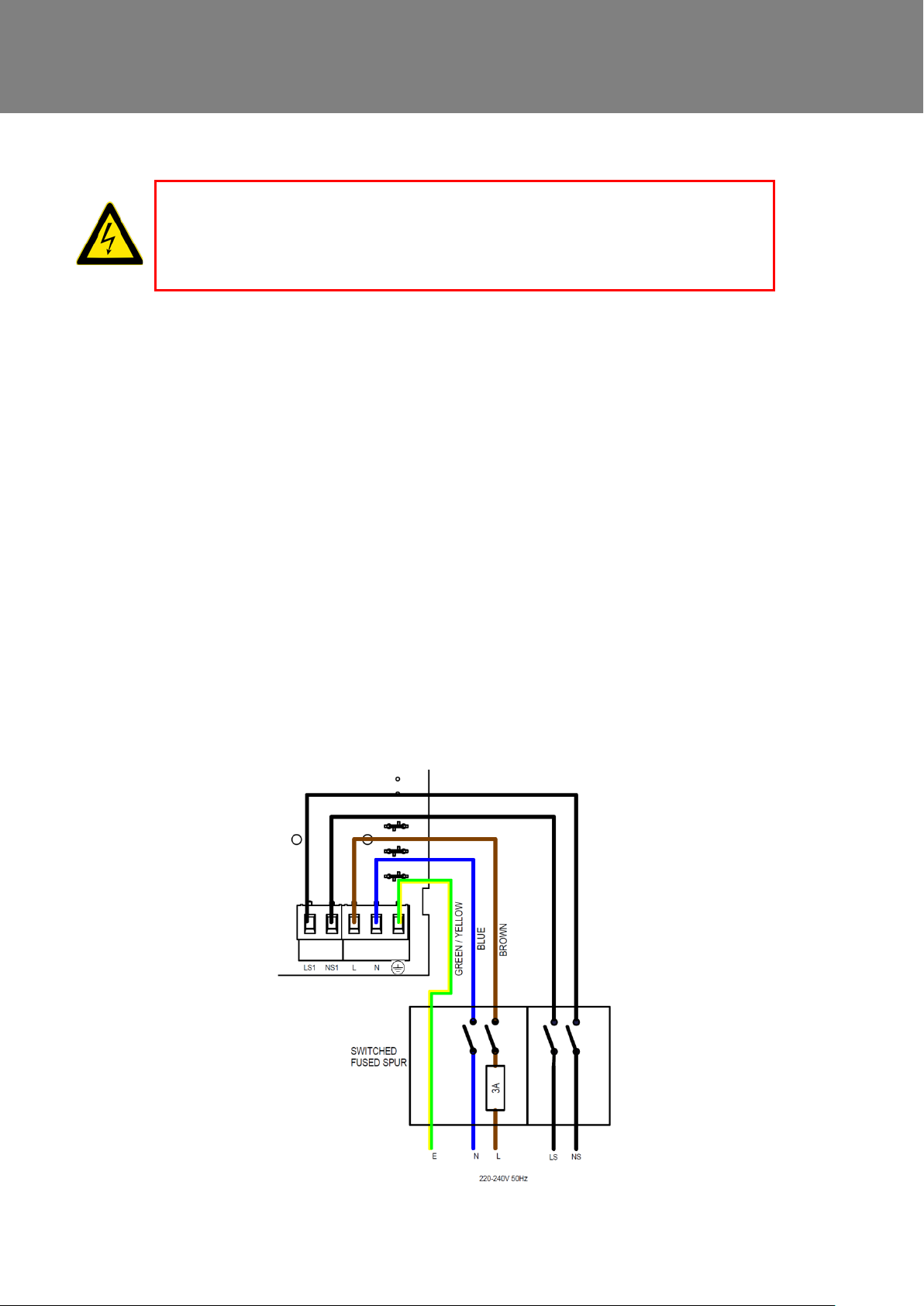
Connect the Power Supply
1. MAINS SUPPLY VOLTAGES (220-240 V AC) ARE PRESENT IN THIS EQUIPMENT, WHICH MAY
CAUSE DEATH OR SERIOUS INJURY BY ELECTRIC SHOCK. ONLY A SUITABLY QUALIFIED PERSON
SHOULD CONNECT THE POWER SUPPLY TO THIS UNIT.
2. THIS UNIT MUST BE CORRECTLY EARTHED.
This unit is designed for operation from a single-phase alternating current source (220-240 VAC).
A 1.5m cable is connected internall y t o the unit for connection to an isolato r switch.
To connect the power supply:
Ensure the local AC power supply is switched off.
One end of the power cable supplied is already connected to the unit in the manner shown above.
Connect the other end of the cable to the switched fused spur.
Use cable clamps and clips to secure the cable, as appropriate.
Connecting a Boost (Light) Switch
WARNINGS
A Switched Live (LS1) may be used to boost the air flow when a light is turned on, for instance in a
bathroom or kitchen. If the LS1 core of the mains cable is not used it should be terminated in an
appropriate manner.
If the unit and the LS1 connection are on the same circuit, the jumper should be left between N and NS1
as shown above.
Connecting a Boost (Light) Switch from a different circuit
If the supply used for the Switched Liv e (LS) is on a different circuit to the power connections, the
connections LS1 and NS1 should both b e connected to the same circuit. LS1 and NS1 are connected to
the unit via a built in isolator and a separate isolating relay is not needed. The factory fitted link wire sh ould
be removed.
28 MVHR Installation and User Guide 476930
Page 29
Commissioning
Powering up the Unit
Switching On
To switch the unit on:
1. Switch on the power at the mains supply isolator feeding the unit.
2. Following switch-on, the fan motors will start and the Control Unit will display a star t-up screen,
described on page 29.
N.B. If you are intending to carry out work or maintenance inside the unit, isolate the supply to the
unit before removing any covers.
Switching Off
To switch the unit off:
1. Turn the power off at the mains supply isolator.
SAP Compliance
The touch-screen controller consumes 0.5W when fitted to the unit and in standby
mode. The SAP PCDB results are achieved with the touch-screen controller removed
from the unit. For SAP compliance, remove the controller from the unit after
commissioning and store in a safe place, See page 25.
Commissioning
Overview
The instructions in this section ar e i ntended to provide configuration and operation information for setting
up the equipment. In the event of problems, see Diagnosing a Problem on page 17.
Follow good practice when commiss i oning the unit. Ensure that the system is installed according to the
system designers intent incorporating any acoustic ducting, that all joints are air tight, ducting is well
supported, bends are avoided clos e to vents, and that the vent valves are fully open at the start of the
commissioning process.
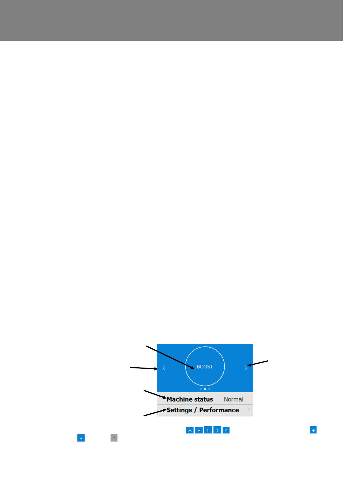
Control Unit Touch Screen Display
The touch screen display can be located on the front of the unit or connected to the unit via a remote
docking kit. The Control Uni t provides the user interface for c ommissioning and monitoring purposes. The
display is a resistive touchscreen with LED backlight, which will turn off to automatically after 5 minutes to
minimise power consumption. To activate the backlight, touch the dis play.
User mode (Boost) button
Scroll Left
Status bar
Scroll Right
Settings & Performance bar
Navigate through the functions by pressing the symbols, adjust settings using t he
buttons. A symbol indicates that t here are further screens related to a menu option. Select the
option on the touchscreen to access the related screens.
MVHR Installation and User Guide 476930 29
Page 30
Commissioning
up the unit for the first time.
menus.
Modifying Settings
If settings need to be changed after t he unit has been commissioned, access to the commissioning menu can be
accessed by following the steps bel ow.
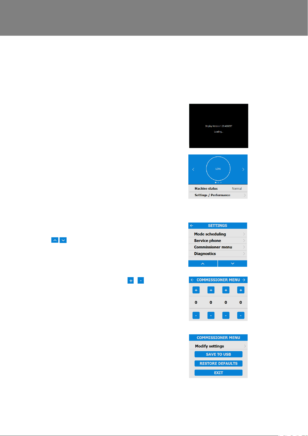
Start up screen
Every time the unit is powered up, the start up
screen appears as the software loa ds showing the
display version.
A Quick Start sequence will appear when powering
User Menu Home Screen
The user menu home screen, consists of a User
Mode (LOW, BOOST, PURGE) button, a Machine
status bar, and a Settings / Performance bar.
The Machine status scrolls through Mode of
operation, Summer bypass status and Frost
protection status.
Press ‘Settings / Performance’ to access the
Scroll down to ‘Commissioner menu’ using the
buttons at the bottom of the screen.
Enter the 4 digit lock code using the /
buttons on the screen to access the commissioning
menu. The default is 0000 and can be c hanged in
the Modify Settings menu.
Press to enter the commissioning menu
Press to return the settings menu
Press ‘Modify settings’ to enter the
commissioning screens.
30 MVHR Installation and User Guide 476930
Page 31
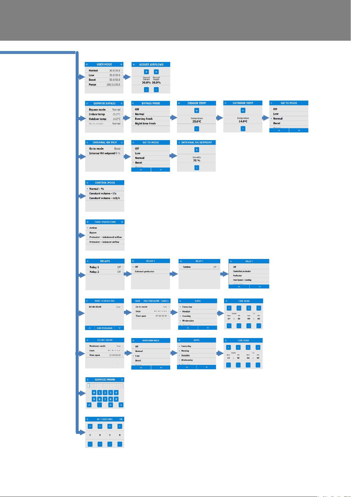
Commissioning Screens Summary
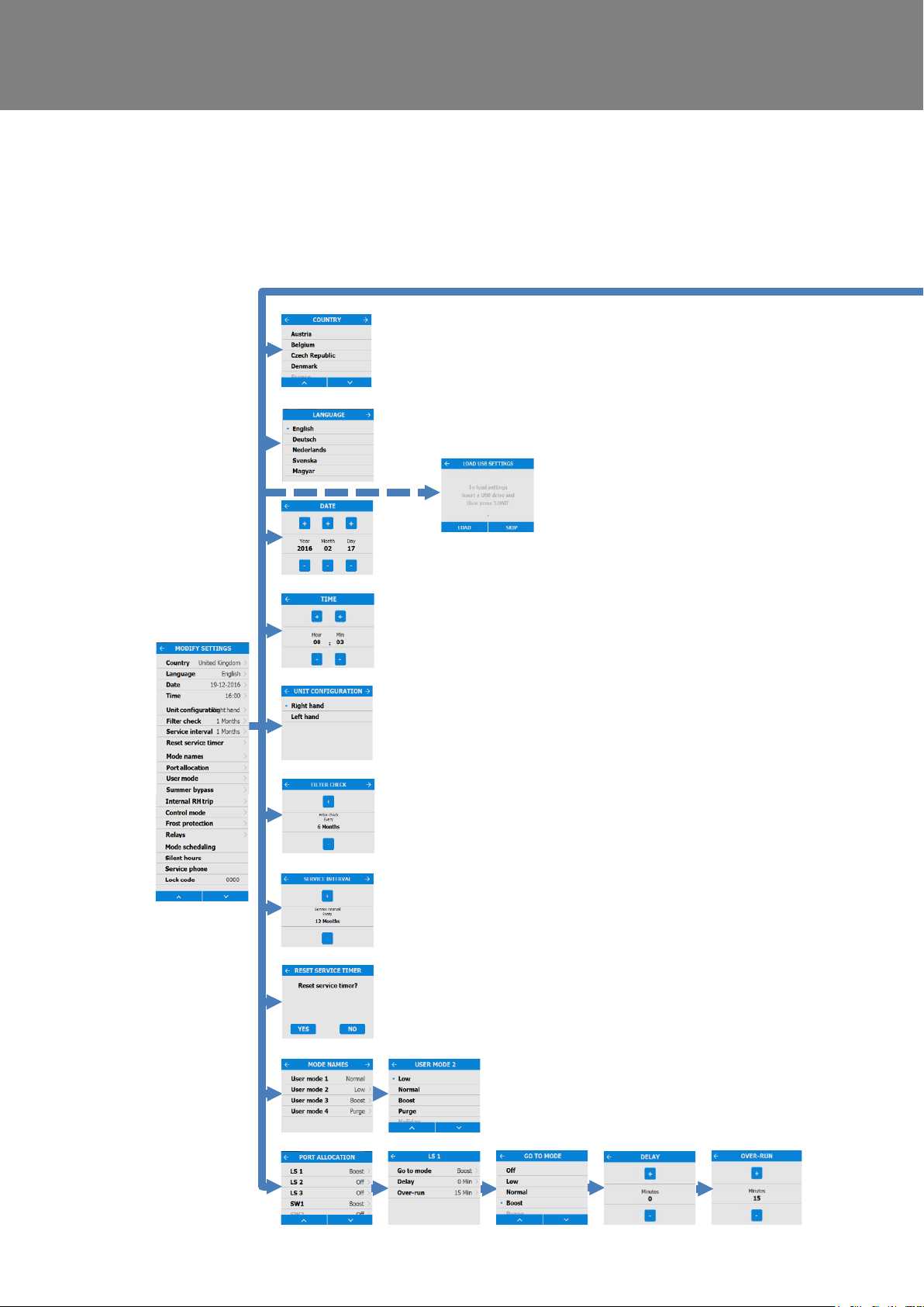
The following pages show all available settin gs within the commissioning menu. Please note that some
settings may not be available, or may be in a different order, due to pre-configuration by your distributer. A
Quick Start sequence will appear when powering up the unit for the first time.
Commissioning
MVHR Installation and User Guide 476930 31
Page 32
Commissioning
32 MVHR Installation and User Guide 476930
Page 33
Modifying Commissioning Settings
Commissioning
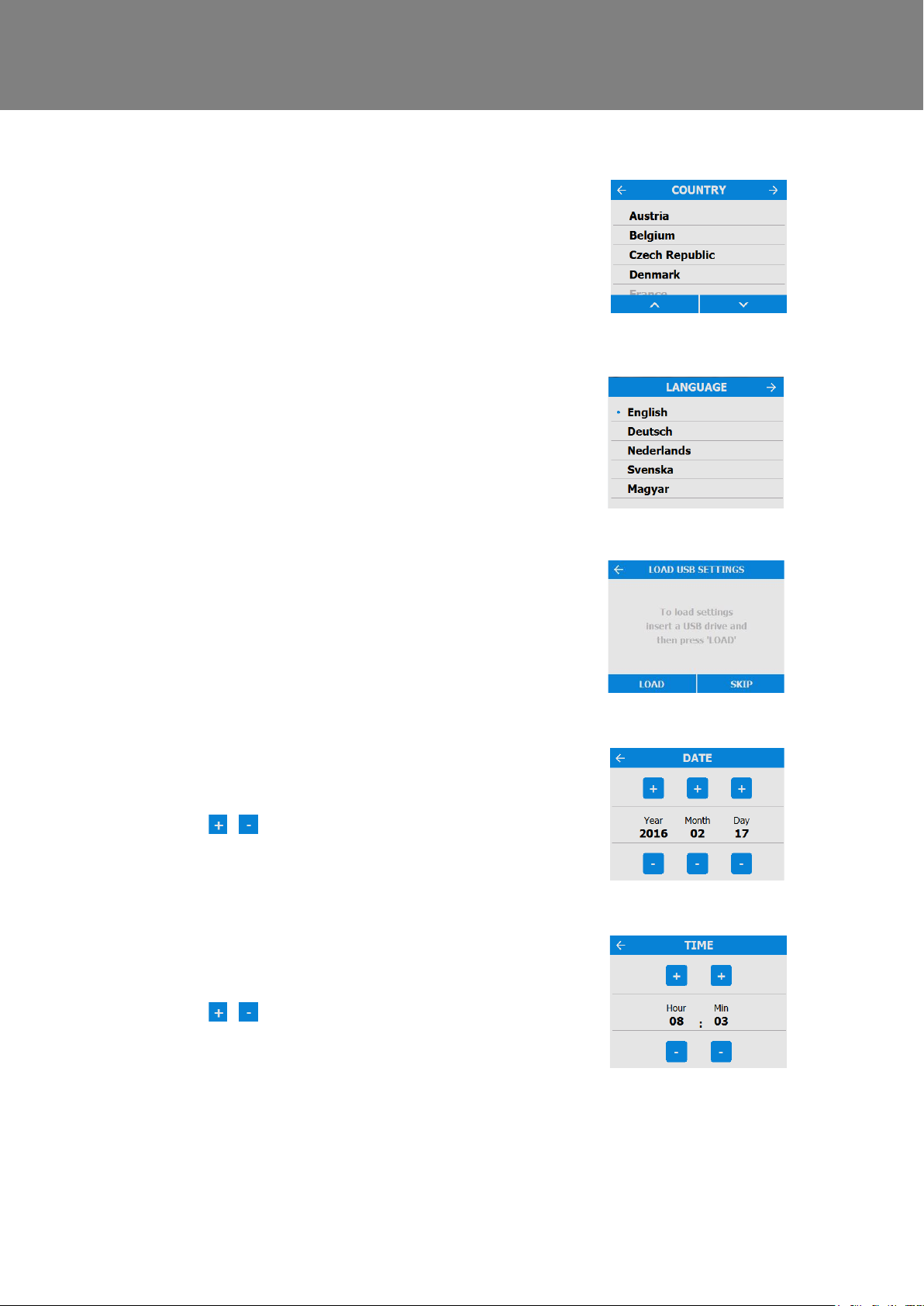
Country
Select country – This will load any pre-determined
national default parameters for all subsequent
screens.
Language
Select language – The language choice does not
affect the defaults setup by the count ry choice.
Load USB Settings
Settings can be automatically loaded to the unit via
the USB port. Note: This option will only appear on
the Quick Start sequence. Access to this screen
can be obtained by using the Restore D efaults
feature.
Date
The Date is pre-loaded as part of the f ac tory
defaults, but may be changed if requir ed using the
/ buttons on the screen.
Time
The Time is pre-loaded as part of the factory
defaults, but may be changed if requir ed using the
/ buttons on the screen.
Note: The clock is 24 hour
MVHR Installation and User Guide 476930 33
Page 34
Commissioning
menu.
intervals.
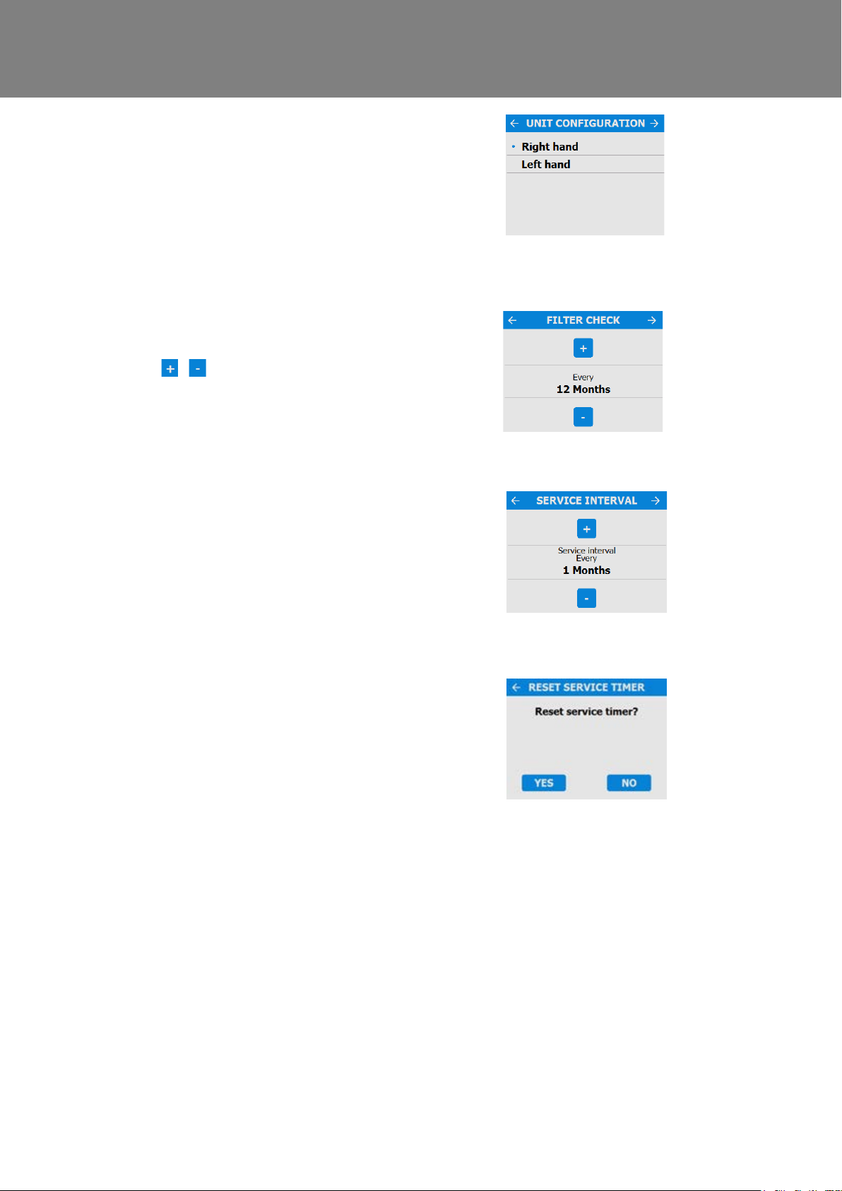
Unit configuration
Select the orientation of the unit dep ending on the
configuration of the installation.
Units with a preheater are preconfigur ed from the
factory and cannot be changed.
See page 18 for a description of t he uni t handing.
Press to save and return to the commissioning
Filter Check
Select the time interval for checking the filters using
the / buttons on the screen, between 1
month and 18 months.
Note: There is an automatic filt er check notification
3 months after installation, irrespective of set
Service interval
Set the service frequency.
Reset Service Timer
After the unit has been serviced, use this option to
reset the timer.
34 MVHR Installation and User Guide 476930
Page 35
Commissioning
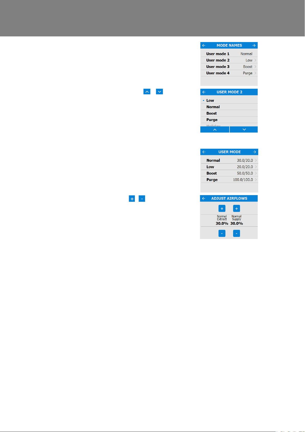
Mode Names
The names and speed for each mode can b e
changed if required.
Note: The user mode 1, Normal, is not editable.
Scroll through the settings using the &
buttons and select the mode pre-set for each User
mode.
Press to save and return to the commissioning
menu.
User Mode
Adjust the supply and extract airflows for each
mode pre-set. Select each mode to adjust to the
required flow rate.
Adjust the airflows using the / buttons.
Press to save and return to the commissioning
menu.
MVHR Installation and User Guide 476930 35
Page 36
Commissioning
specification.
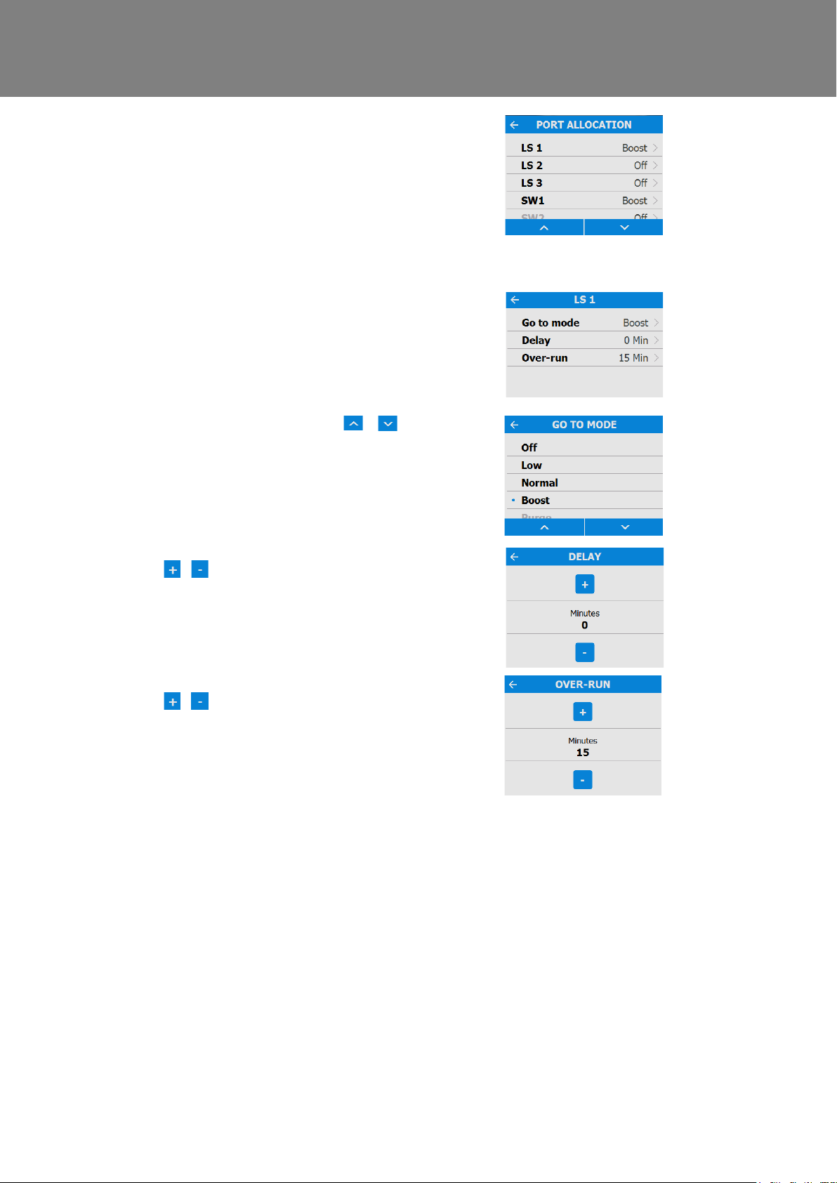
Port Allocation
The unit will automatically detect the following
inputs:
- Wired to the lighting
- Current sensors
- Momentary switch
Note: Number of available ports and port types
may differ from image shown depending on unit
Select the Port to view the Go To Mode (speed
setting), Delay and Over-run parameters.
Select the parameters to edit them.
Scroll through the settings using the &
buttons and select the Go To mode for each Port
Allocation.
Adjust the time delay for each Port Allocation using
the / buttons. Selectable range is 0-20
Adjust the Over-Run for each Port Allocation using
the / buttons. Selectable range is 0-30
36 MVHR Installation and User Guide 476930
Page 37
Commissioning
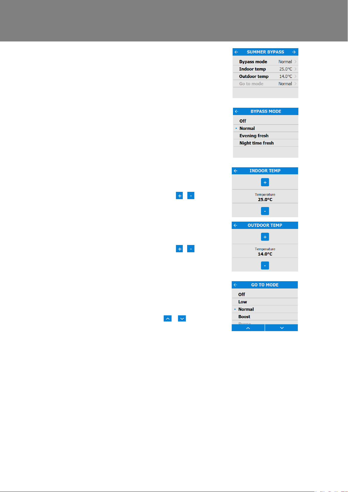
Summer Bypass
See page 59 for a full description of the Summer
Bypass modes and functions
Select the required bypass mode.
The indoor temperature setting is the maximum
desired room temperature. This should be set to 3°
above the central heating temperature.
Change the indoor temperature usin g the /
buttons on the screen.
The outdoor temperature is the minimum air
temperature that the bypass will permit. This is to
prevent cold draughts.
Change the indoor temperature usin g the /
buttons on the screen.
This is the mode the bypass will switch to when
activated.
The suggested Mode for Evening fresh and Night
time fresh setting is Boost.
Scroll through the settings using the &
buttons and select the Go To mode.
Note: Number of available modes may differ from
image shown depending on bypass s etting and the
modes set in the commissioning proces s.
MVHR Installation and User Guide 476930 37
Page 38
Commissioning
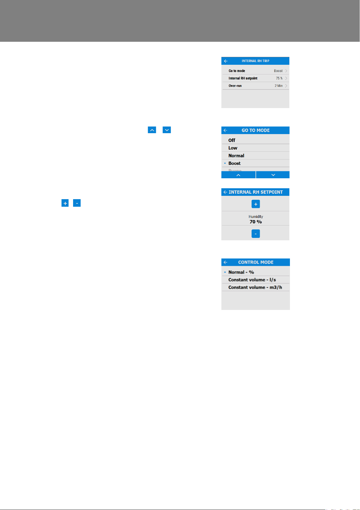
Internal RH Trip
The integral humidity sensor increases airflow
speed in proportion to relative humidity levels. The
sensor also reacts to small but rapid increases in
humidity, even if the normal trigger threshold is not
reached. The night time relative hum idity setback
feature suppresses nuisance tripping as humidity
gradually increases with falling temperature.
Scroll through the settings using the &
buttons and select the required Go To mode.
Adjust the internal Relative Humidity using the
/ buttons. Selectable range is 60% - 90%.
Internal RH sensing can be switche d off by
selecting “OFF”, this option is above 90%, or below
60%.
Control Mode
Select whether the unit should operate in Normal or
Constant Volume mode.
38 MVHR Installation and User Guide 476930
Page 39
Commissioning
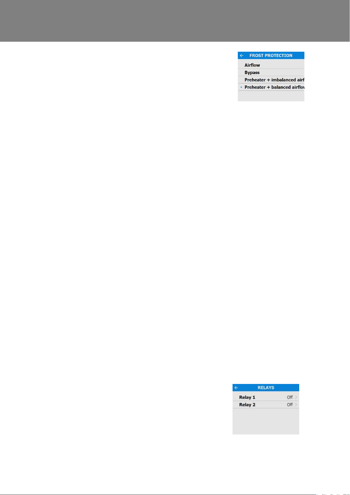
Frost Protection
Frost Protection is required to prevent condensate
freezing in the heat exchanger at low temperatures.
The process is fully automatic. T he method used
for frost protection will depend on the model and
building it is installed in.
For buildings with a leak rate of 3m
50Pa), a balanced frost protect i on mode must be
used. A balanced mode must also be used when a
combustion device without a dedicated air supply is
present.
Airflow (Imbalanced)
Airflow mode reduces the Intake flow and
increases the Extract flow in var ying proportions
dependent on the incoming air temper ature. The
unit will continue to recover heat as low as -20C. At
this point, the unit switches to 'Extrac t Only' mode.
Bypass (Balanced)
Bypass mode opens the Summer Bypass an d
stops recovering heat until the external
temperature increases sufficiently.
3
/hr or less (at
Airflow & Preheater (Imbalanced)
If a preheater is fitted, the preheater will turn on to
warm the incoming air to above freezing. If the air
temperature is so low that the heater cannot warm
the air sufficiently, the supply flow rate will be
reduced to compensate.
Airflow & Preheater (Balanced)
If a preheater is fitted, the preheater will turn on to
warm the incoming air to above freezing. If the air
temperature is so low that the heater cannot warm
the air sufficiently, both the su pply and extract flow
rate will be reduced to compensate.
Relays
Select whether the external prehe ater outputs are
activated. These outputs are 230V 5A m aximum
each.
MVHR Installation and User Guide 476930 39
Page 40
Commissioning
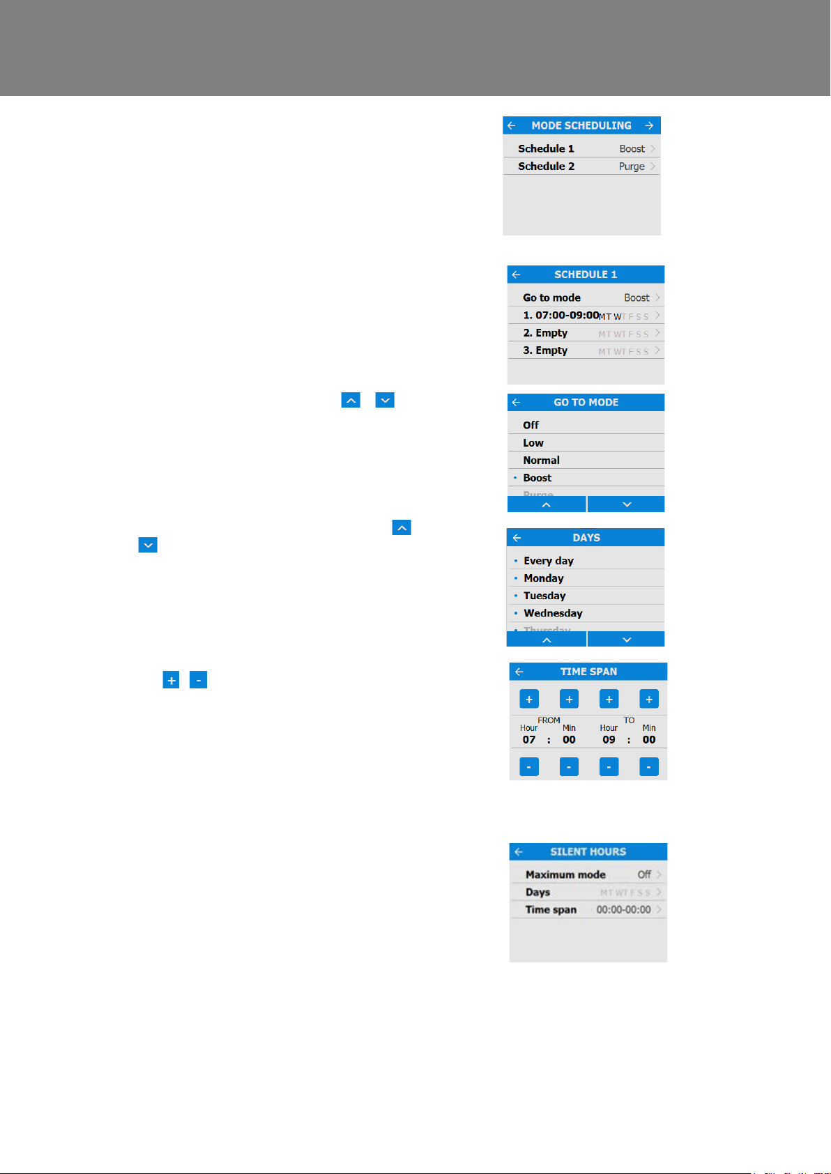
Mode Scheduling
Use a schedule to set a Mode (Airflow setting) for a
fixed, repeated period. For exampl e, set Boost
Mode every morning between 7:00am and 8:00am
while cooking breakfast.
Select the Schedule to view the settings
Scroll through the settings using the &
buttons and select the Go To mode for each
Schedule.
Scroll through the days of the week us ing the &
buttons and select each day to be included in
the Schedule program.
Adjust the start and finish times f or each day using
the / buttons.
Silent Hours
Silent Hours mode is useful to impose a speed/flow
restriction on the unit to minimise unwanted noise
during the night.
If Silent hours are enabled, the unit will not speed
up above the set Maximum Mode. Silent Hours can
be set to reoccur on specific da ys and times.
40 MVHR Installation and User Guide 476930
Page 41
Commissioning
buttons.
screen.
return to the Commissioning Home sc reen
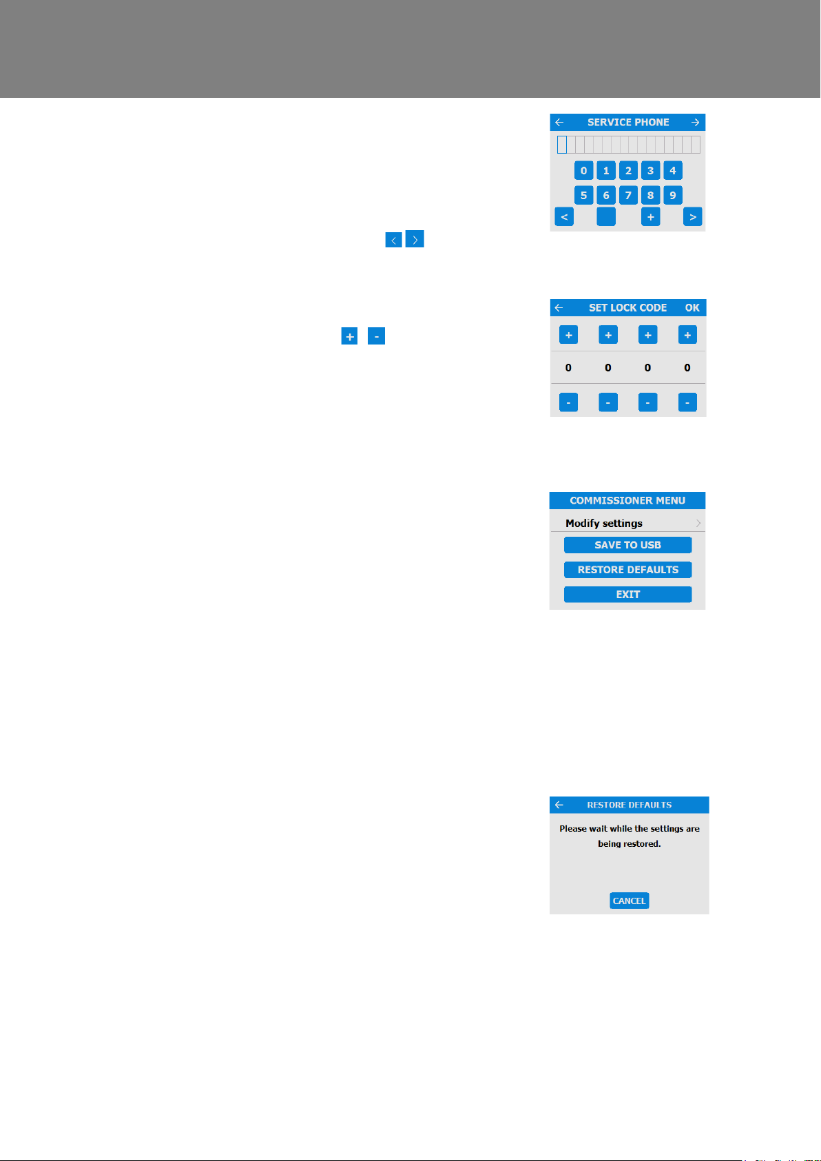
Service Phone
The Service Phone screen enables the installer to
enter the telephone number that shoul d be called
for service in the event of a unit fault or for routine
maintenance.
Enter the number using the buttons on the screen,
Scroll through the number using the
Set Lock Code
Set the lock code using the / but tons on the
screen, press OK to save the code.
Note: Default code if not set at this point will be
0000.
Commissioner Menu
Once the commissioning settings have been
modified exit to the commissioning menu.
Settings are stored in a non-volatile memory and
will be retained irrespective of mains supply
breaks, however, the unit can also be restored
back to factory defaults at this scr een.
Press EXIT to return to the User Menu Home
To complete the setup process, pres s the EXIT
button.
If a USB device is present, the settings from the
unit can be saved and used for the setup of s i m i lar
units.
Restore Defaults
To return the unit back to factory settings press the
Restore Defaults button. A confirm ation screen will
appear. Press YES to confirm, or CANCEL to
Once confirmed the following scr een will appear,
the restore process takes approxim ately 5 seconds.
Press CANCEL to stop the restore process during
this time.
Once the system has restored back to fac tory
default settings it will go back to t he s tart up
screens.
MVHR Installation and User Guide 476930 41
Page 42

Commissioning
Commissioning the Unit via USB
When carrying out commissioning on multiple similar installati ons , commissioned settings may be downloaded and
saved onto a USB at the end of the setup routine (see page 40). They can then be uploaded onto subsequent units
saving time on site. The option to uplo ad the settings is available at the begi nning of the commissioning quick st ar t
menu (see page 29 & 32).
No two systems are exactly the same and the settings and flow rates at eac h i ns tallation should be verified.
The USB does not have to be blank however only the most recent file will be read.
42 MVHR Installation and User Guide 476930
Page 43

Accessories
Accessories
Accessories
• WIFI Controller Accessory 409195
The WIFI controller is a plug & play acc essory that fits next to the Control module. This offers the user
instant access to various functions and features for direct monitoring and control of the unit using a smart
phone or tablet via the Vent-Axia mobile application.
• Volt-Free Input Switch PCB Accessory 472697
The optional Input Switch Accessory offers four volt-free pairs of switch terminals to allow boosting f rom
manual switches or a full range of Vent-Axia controllers e.g. humidistats, PIRs and timers.
• Switched Live expansion PCB Accesso ry 472699
The optional Switched Live (LS) expansion accessory offers two extra switched live inputs (LS2 and LS3)
for boosting via light switches (220-240V AC) or Normal/Boost switch. This connection has the advantage
of Delay and Over-run features.
Delay enables the prevention of boost airflow between 1-20 minutes.
Over-run enables boost airflow to co ntinue after the light switch has been turned off between 1-30 minutes
• Analogue Input PCB Accessory 472701
The Analogue Input Accessory has t wo terminals with 0-10V inputs to allow proportional 0–10V control by sophisticated controllers such as CO2 sensors and proportional humidistats.
• Wired Remote Docking Kit Accessory 474491
The Controller Docking Kit has been d es igned to allow the Controller mo dule to be removed from the
MVHR & mounted remotely to either a single or double gang flush mount back -box of 25mm depth (min).
The kit is supplied with a 15m lead and control panel cover.
• Opto-coupler Accessory 447340
The LED terminals are intended to driv e a remote LED to indicate that a fault has occurred.
• Remote LED Indicator and Lead Accessory 448356
Remote LED to indicate that there is a message in the control display.
Further information regarding these alternative control options i s available at the back of this document, Please
contact your supplier for availabili ty in your region. Some accessories may be included as standard equipment
depending on unit version, please check before ordering.
MVHR Installation and User Guide 476930 43
Page 44
Accessories
WiFi Controller
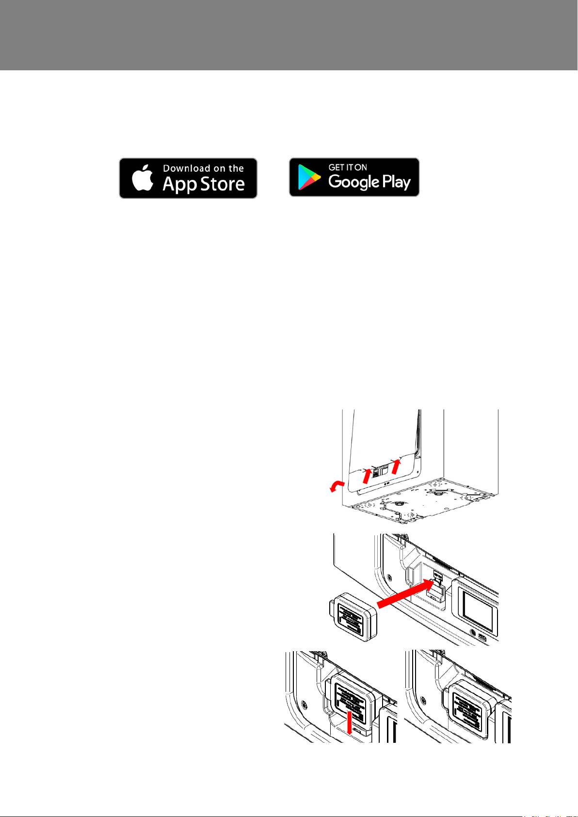
The WiFi controller is a plug & play accessory that fits next to the control module. It allows the user instant
access to commissioning, configuration, direct monitoring and control of the MVHR unit, using a smart phone
or tablet with the Vent-Axia Connect app, av ai labl e from the iTunes Store or on Google Play.
Device Compatibility
iOS
The app is compatible with the following iOS devices:
• iPhone 4s (or newer)
• iPod touch (5th generation or newer)
• iPad (3rd generation or newer)
Android
The app is compatible with most Android devices equi pped with Bluetooth 4.0 and running Android 4.3 (Jelly
Bean) or later
Installation
Installation must be carried out by a competent per son.
Installation may be carried out without removing power from the
unit, provided no screws are removed.
Step 1: Remove the outer cover by pressing the tabs either
side of the control module and lifting the cover outwards from
the bottom edge.
Step 2: Insert WiFi module into slot to the left of the
touchscreen control module.
Step 3: The WiFi controller status LED illum i nates when the
module is fitted correctly.
Step 4: Connect phone or tablet device to WiFi network using
the AP SSID (network name) indicated on the WiFi co ntroller.
Status LED will indicate green when connected.
Step 5: Use the app to connect to the unit, either using the
phone camera, or entering the device name and
security key indicated on the WiFi controller label .
Step 6: Replace outer cover.
.
• iPad mini
• iPad air
44 MVHR Installation and User Guide 476930
Page 45
Accessories
not configured to communicate online .
from the App.
device to the app.
of the label.
the WiFi controller.
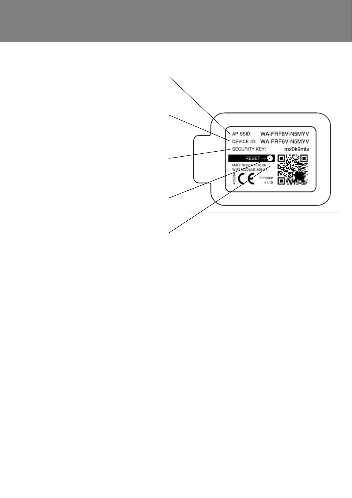
Understanding the product label
AP SSID
The name of the wireless network
hosted by the WiFi controller when it i s
DEVICE ID
The name the WiFi module identifies as
when selecting a device to configure
SECURITY KEY
The pass-phrase required to enable
secure communications with WiFi
controller, required when adding the
RESET BUTTON
A reset button is hidden behind this area
STATUS LED
A tri-colour LED is placed behind this
area of the label, indicating the s tatus of
Resetting the WiFi Controller
A reset button is provided behind the label on the front of the WiFi Controller. It may be accessed by
piercing the label with a small screwdriver in the position indicated on the label.
Short Press (< 5 seconds)
A press less than 5 seconds shall toggle the WiFi controller between ‘Temporary AP’ and ‘WLAN’
modes (if the unit is configured for WLAN access ). Us e this if the WiFi status indicates ‘WiFi error’ to
correct network settings.
Long Press (≥ 5 seconds) - Reset to fact ory defaults
A press longer than 5 seconds shall put the WiFi cont roll er into ‘reset confirm’ state, with a fast red LED
flash. To confirm the intent to reset to factory defaults, press and hold the reset button for a further 5
seconds. The LED will change to solid red to confirm i t is res etting and will reboot when the button is
released.
Supportsed Networks
The WiFi controller supports IEEE 802.11 b/g/n networks at 2.4GHz using the following network
security:
• Open
• WEP
• WPA
• WPA2
MVHR Installation and User Guide 476930 45
Page 46
Accessories
Troubleshooting
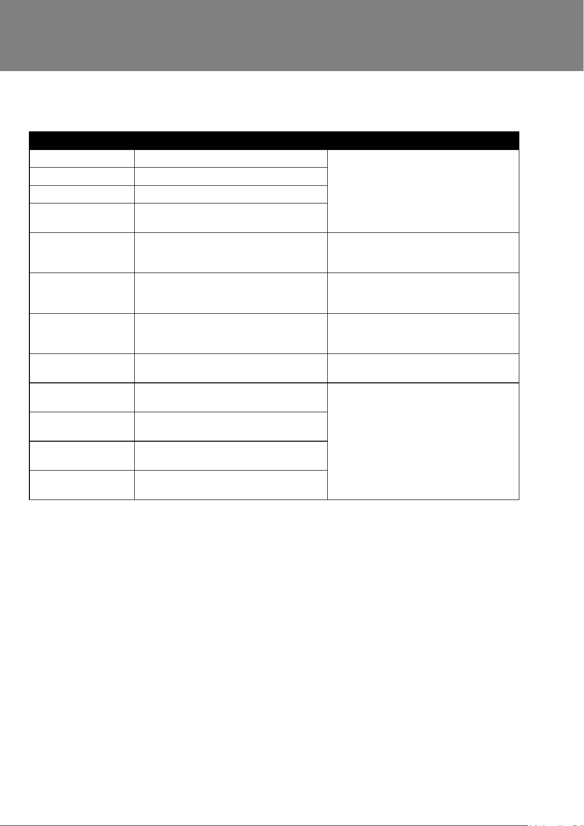
LED Status Description Actions
Solid blue
Slow blue flash
Solid green
Fast green flash
Solid yellow
Fast yellow flash
Slow red flash
Fast red flash
Solid Light Blue
Solid Purple
Solid Red
Initialising
Connecting to a wireless network
Connected to a wireless network
Active communication with a connected
network
WiFi controller is hosting a temporary
network, without a device currently
connected
Active communication & weak signal
WiFi error (e.g. cannot connect to
network)
Factory defaults reset confirm
Bootloader mode
Should not appear in normal operation
Network controller update mode
Should not appear in normal operation
Communications fault between
mainboard and WiFi controller
None - normal operation
Connect phone or tablet to the AP SSID
(network name) indicated on the WiFi
controller
Move existing or introduce additional
WiFi access point closer to the MVHR
unit.
Configure WiFi controller in temporary
access point mode (see previous page)
and correct network settings
See previous page regarding resetting
the WiFi controller
Isolate power to the MVHR unit, wait 30
seconds and re-power the MVHR.
If this fault persists, contact your
distributor support for further assistance.
Slow Flash -
Red / Green
Internal fault on WiFi controller
46 MVHR Installation and User Guide 476930
Page 47
Accessories
Input Switch Accessory
WARNING
THE FAN AND ANCILLARY CONTROL EQUIPMENT MUST BE ISOLATED FROM
THE POWER SUPPLY DURING ANY MAINTENANCE AND WHEN FI T TING THIS
CONTROL MODULE.
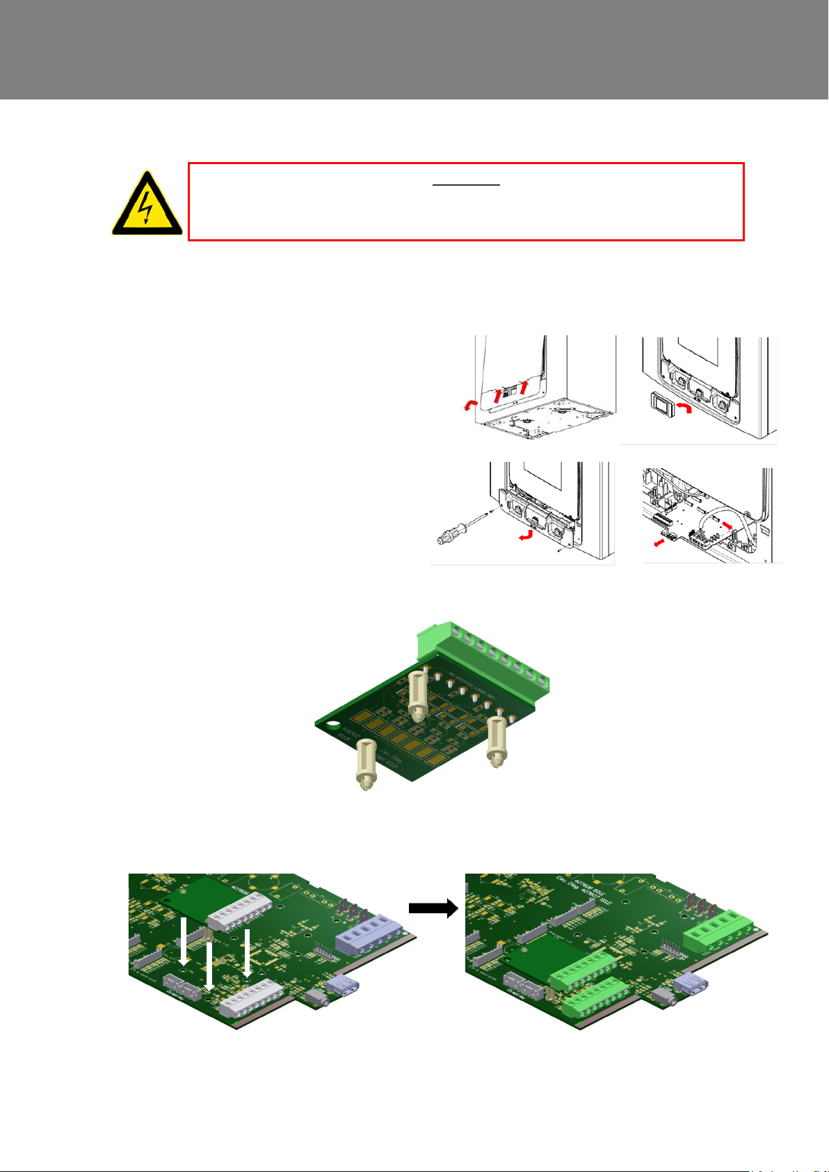
The volt free Input Switch accessory board has four in put s for volt free contacts, allowing up to four
independent switched inputs to be used.
Installation
1. Access the main printed circuit board
following the electrical installation
instruction in the “Installation &
Commissioning” sections of this document.
2. Fit the three plastic stand-offs provided, into the three holes in the Input Switch PCB.
3. Fit the Input switch PCB to the main PCB in position shown.
MVHR Installation and User Guide 476930 47
Page 48
Accessories
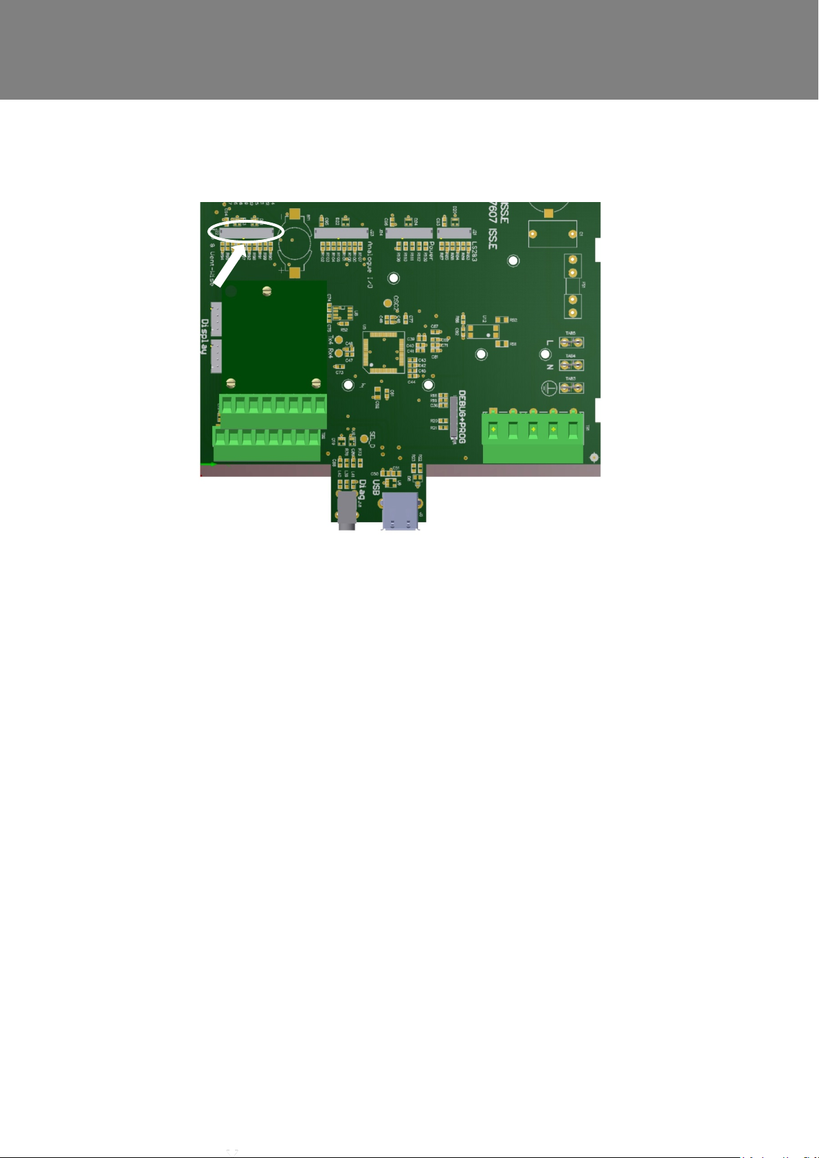
4. Connect the lead from Input Switch PCB into the socket on the left hand side of the PCB marked
“I/P VentWise”.
5. For cable routing from the switches into the unit, refer to the electrical installation instruction
on page 25.
6. Connect the lead from each switch into the terminal block, one wire in the + and the other in t he -.
7. Before fitting the covers, note whi ch terminals have been used.
8. Replace the covers and turn it on.
9. Activate each switch input in turn to ensure functionality.
10. To adjust the speed for each input refer to the Installation & Commissioning sections of t hi s
document and go to the commissioning menu and f ol l ow t he steps to change speeds.
48 MVHR Installation and User Guide 476930
Page 49
Accessories
Switched Live Expansion PCB Accessory
WARNING
THE FAN AND ANCILLARY CONTROL EQUIPMENT MUST BE ISOLATED FROM
THE POWER SUPPLY DURING ANY MAINTENANCE AND WHEN FITTING THIS
CONTROL MODULE.
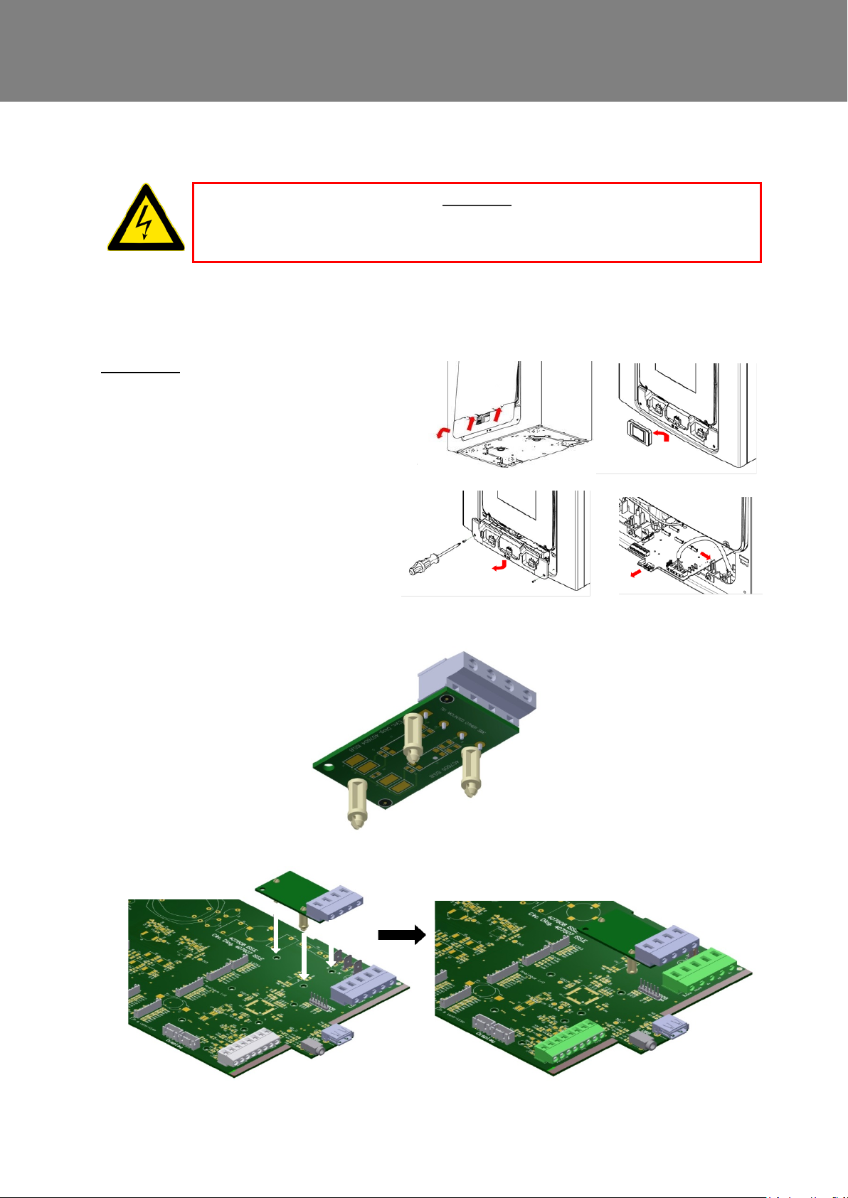
The LS2/3 accessory board has two independent LS (S wit ched live) inputs which can be connected to
switches on different circuits to the power circuit of the MVHR unit.
Installation.
1. Access the main printed circuit board
following the electrical installation
instruction in the “Installation &
Commissioning” sections of this
document.
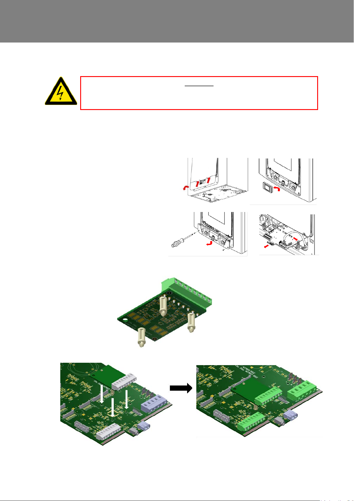
2. Fit the three plastic stand-offs provided into the three holes in the LS2/3 PCB.
3. Fit the LS2/3 PCB to the main PCB in positi on shown.
MVHR Installation and User Guide 476930 49
Page 50
Accessories
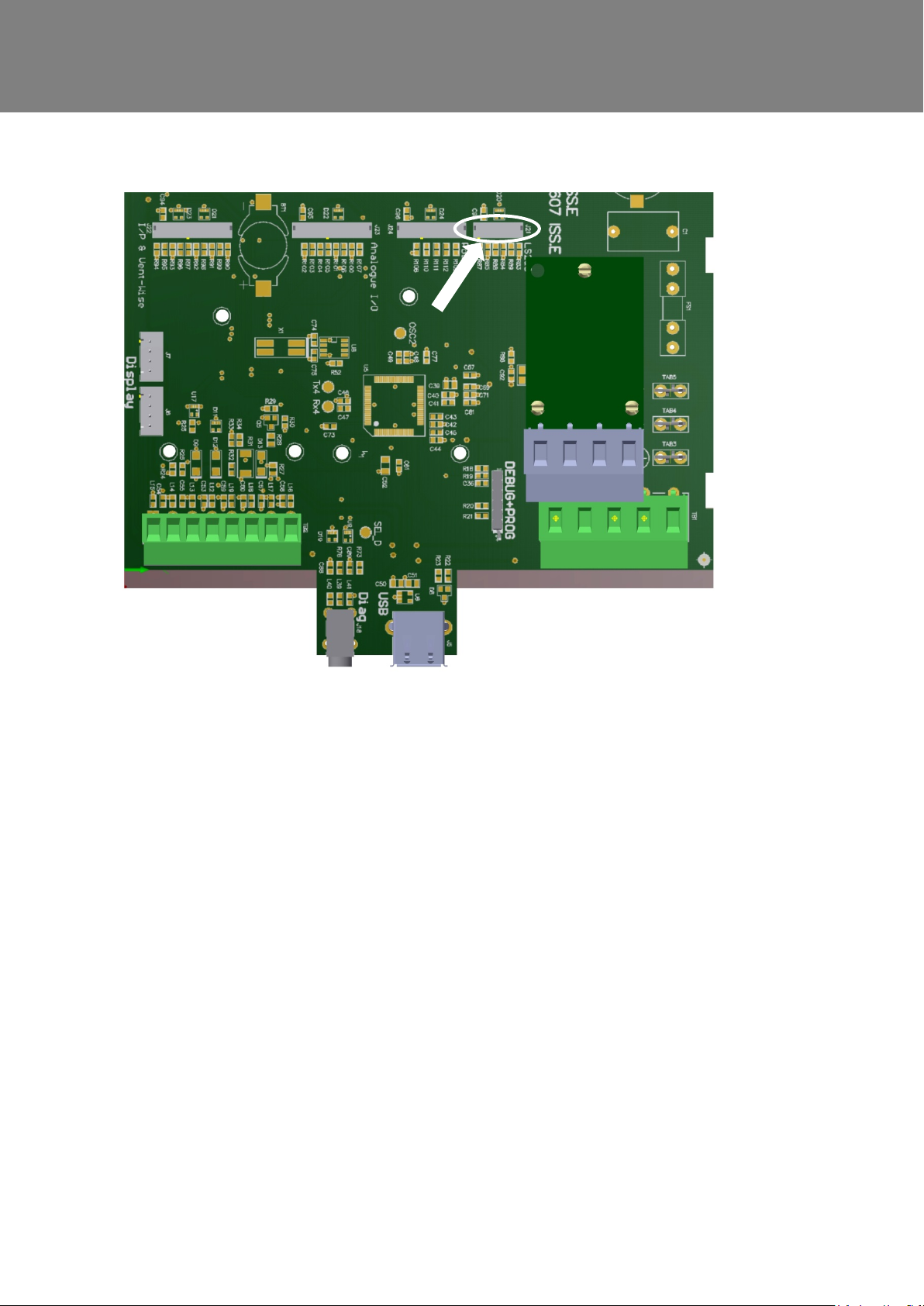
4. Connect the lead from LS2/3 PCB int o the so cket J21 shown below.
5. For routing the wires into the unit reference the electrical installation instruction on page 25.
6. From the required circuit, take the switched live and the neutral. Connect the switched live wire to the
terminal marked LS2 and the neutral wire to t he t erm inal m arked NS2. For additional circuit use
terminals LS3 and NS3.
7. Replace the covers and turn it on.
8. The LS2 & 3 input can be set up with delay on, over run and boost speed, refer to the Installation &
Commissioning sections of this document to change settings.
9. After set up, test the LS input functi ons as required.
50 MVHR Installation and User Guide 476930
Page 51
Accessories
Analogue Input PCB Accessory
WARNING
THE FAN AND ANCILLARY CONTROL EQUIPMENT MUST BE ISOLATED FROM
THE POWER SUPPLY DURING ANY MAINTENANCE AND WHEN FITTING THIS
CONTROL MODULE.
The analogue input (I/O) PCB accessory has two 0-10V inputs for proportional sensors, and two 0-10V
outputs for proportional dampers. Note: The pr oportional sensors and dampers require their o wn power
supply.
Installation.
1. Access the main printed circuit board
following the electrical installation
instruction in the “Installation &
Commissioning” sections of this
document.
2. Fit the three plastic stand-offs provided into the three holes in the Analogue input PCB.
3. Fit the Analogue input PCB to the Mai n PCB in position shown.
MVHR Installation and User Guide 476930 51
Page 52
Accessories
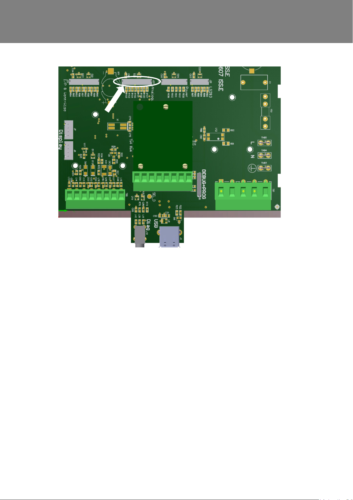
4. Connect the lead from Analogue I/O PCB into the socket marked “Analogue I/O” shown bel ow.
5. For routing the sensor leads into the unit, reference the electrical installation instr uct ion
on page 25.
6. For the siting of the Temperature, Humidity and CO2 proportional sensors refer to their
instructions.
7. For connecting proportional sensors, connect the ground (0V) from the sensor to the t erminal P1-
of Analogue board and the 0–10V signal from senso r to the terminal P1+ of Analogue board. For
additional sensor repeat above using P2 terminal.
8. For the siting of the proportional dampers refer to their instructions.
9. For connecting proportional dampers, connect the ground (0V) from the damper to t he t erm inal
V1- of Analogue board and the 0–10V signal input from damper to the terminal V1+ of Analogue
board. For additional sensor repeat above using V2 t erm inal .
10. To set up the speed, type and operating range, refer to the Installation & Commissioning sections
of this document to change settings.
11. After set up, test the inputs and outputs function as required.
52 MVHR Installation and User Guide 476930
Page 53
Accessories
Wired Remote docking Kit Accessory
WARNING
THE FAN AND ANCILLARY CONTROL EQUIPMENT MUST BE ISOLATED FROM
THE POWER SUPPLY DURING ANY MAINTENANCE AND WHEN FITTING THIS
CONTROL MODULE.
The Wired Controller Docking Kit is designed so that the Control Module on the MVHR unit can be
mounted remotely. The Docking module is designed to fit a single or double gang flush mounting back
box with a min. depth of 25mm.
The Kit contains the 1 x Docking module, 1 x 15m connection cable, 1 x blank cover and mounting
screws.
Installation.
1. The main printed circuit board following the electrical installation instruction in the Installation &
Commissioning sections of this document.
2. Site the Docking module at a height of 1.5m from the floor and within the distance of a 15m cable
run from the kinetic Advance unit. Do not extend the cable provided.
3. Fit the Connection cable provided into the back box , feed the cable through to the MVHR unit with
the plug in terminal connector end at the back box. A void routing cable alongside mains power
cable.
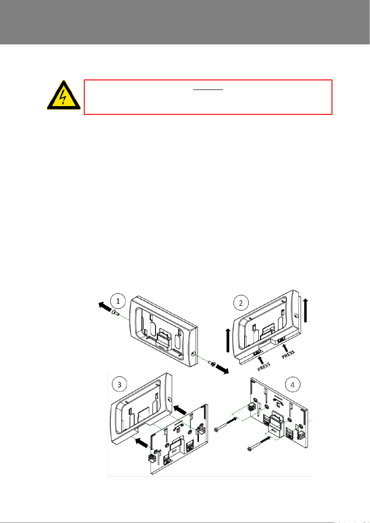
4. To fit the Docking module to the back box, first remove the two screws, one either side.(1) Slide up
the front fascia then press the two tabs at t he bottom.(2) This will release the 2 clips that are
retaining the front fascia. You can now slide up the fas ica as far as it will go and lift it off the back
section.(3) Fit the cable connector to the socket on the back section. Fit the back section to the
back box by using two screws supplied with the back box. (4) Refit front fascia in reverse order of
its removal.
MVHR Installation and User Guide 476930 53
Page 54
Accessories
Terminal ref - A
Black
Black
Terminal ref - B
White
Orange
Terminal ref - C
Green
Brown
Terminal ref - D
Red
Red
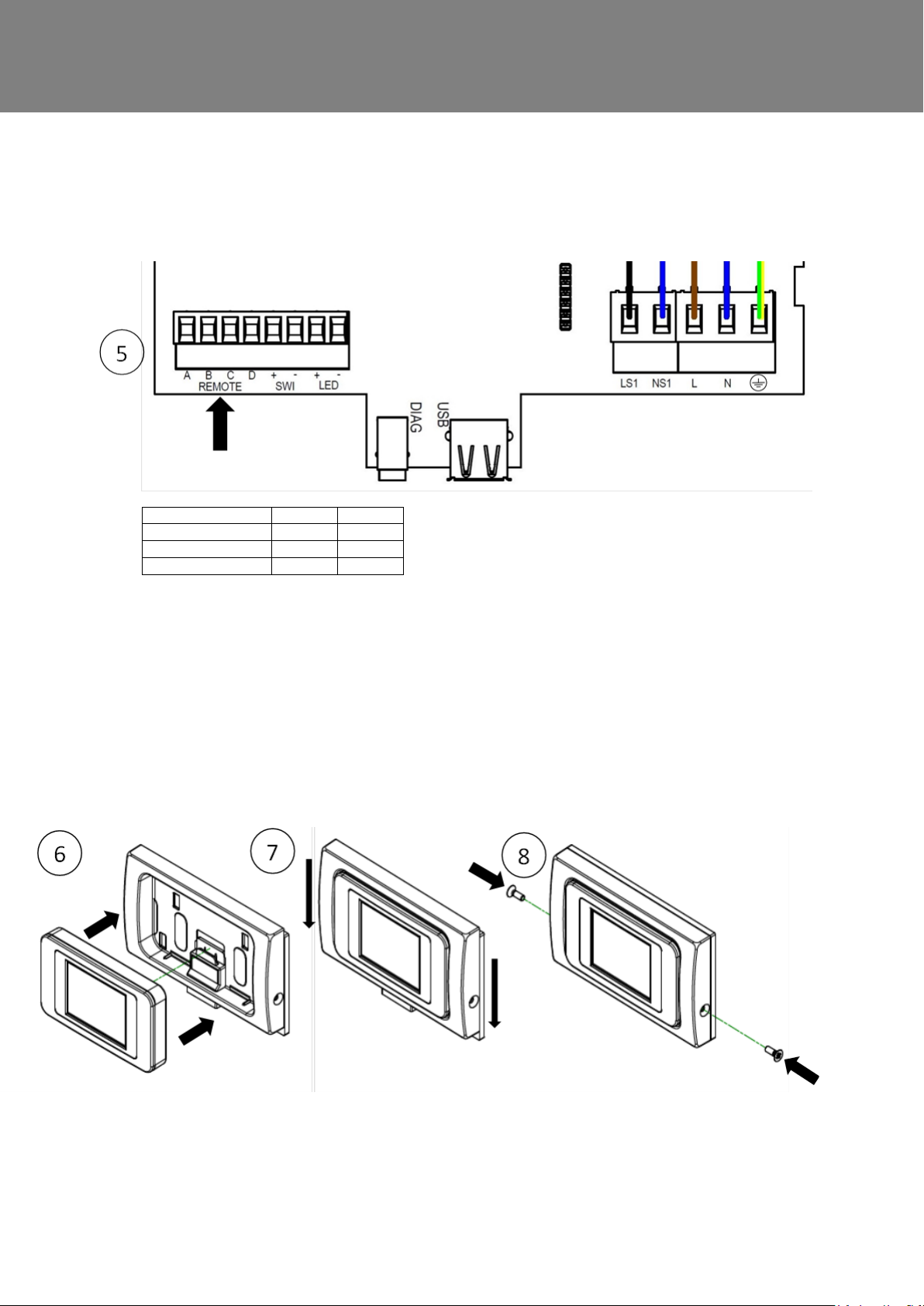
5. For routing the cable from the Docking module into the Kinetic Advance, reference the electrical
installation instruction in the “Installation & Commissioning” document suppl i ed with your unit. The
cable should be routed in on the left hand side of unit.
6. The cable is connected to the terminal block TB2 EXTE RNAL REMOTE/LED/SW1 at A, B, C and D
terminals. The cable has one of two wire colour codes and should be connected in the order shown
in the table below. (5).
7. To remove the display controller from the unit pus h up the units front panel. This will give you
access to the controller. Remove the controller and repl ace it with the blanking cover provided.
8. Refit the front panel on the unit.
9. To fit the display controller to the docking module f irst ensure that the two side screws are
removed. Push the front fascia up until it stops. Ins ert the display controller module into the docking
module. (6) Push down the front fascia to enga ge the display controller module with the contacts.
(7) Refit both side screws (8).
10. Turn on the unit and check that the controller w orks.
54 MVHR Installation and User Guide 476930
Page 55
Accessories
Opto-coupler Accessory
WARNING
THE FAN AND ANCILLARY CONTROL EQUIPMENT MUST BE ISOLATED FROM
THE POWER SUPPLY DURING ANY MAINTENANCE AND WHEN FITTING THIS
CONTROL MODULE.
Connecting an Opto-coupler
The LED terminals are intended to drive a remote LE D t o indi cate that a fault has occurred. They
provide a LED driving signal output between the + and – terminals that enables remote indication
of a unit fault. See the Control Panel for fault code (See page 17). This signal could also be used
by a BMS system so that its informed that a fault has oc curred. If a volt-free contact is required
then use this opto-coupler to provide electri cal separation.
Connect the flying leads of the opto-coupler pcb i nto the LED terminals, + to + and - to Connect the pair of leads from the BMS to the terminal block of the opto-coupler pcb. Polarity does
matter here.
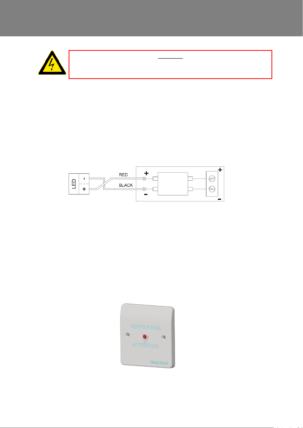
Remote LED Indicator and Lead Accessory
The LED terminals are intended to dri ve a remote LED to indicate that ther e i s a message in the control
display.
They provide a LED driving signal output between the + and – terminals that enables remote indication of
filter check or unit fault. See the Control Panel for message (See page 17 f or fault codes).
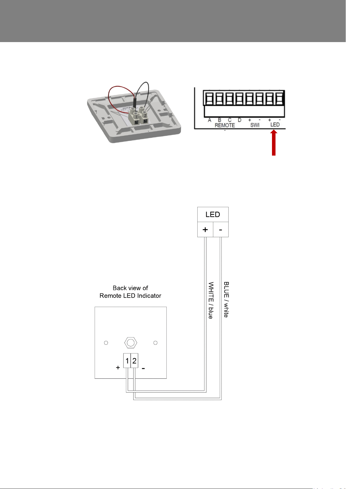
Connect the 2 core flying lead fr om the Remote LED indicator terminal block. Terminal 1 on the Remote
LED is + and terminal 2 is –
MVHR Installation and User Guide 476930 55
Page 56
Accessories
Connect the other end of the lead to the LED + &- terminals on the Kinetic unit PCB. Please ensure that the
+ goes to + and the – goes to -.
56 MVHR Installation and User Guide 476930
Page 57

Technical data
- Low
- Night time
- Normal (Unit default operating mode)
- Party
- Boost
- Unoccupied
- Purge
- Over pressure
- Holiday
- Fireplace
Flow Rate settings
The Sentinel Kinetic Advance has four (4) user defined speeds in addition to the non-adjustable Maximum speed.
User defined speeds can be assigned a Mode name from the list below. (some opt ions may not be available in your
region)
Note: The flow rate for each mode is set independently and not defined by the m ode name.
When setting up Over Pressure or F i r eplace Mode, the supply rate must b e set higher than extract rate. This is to
provide a positive internal press ur e i n the dwelling to assist with the initial expulsion of combustion products from the
fireplace via the flue.
Fireplace mode does not prevent under-pressure
Mechanical Ventilation with Heat Recovery (MVHR) systems are not designed to provide combustion air.
NOTE: It is the responsibility of the open-flued appliance installer to ensure conformance with the curre nt local
building regulations for fuel bur ning appliances.
Frost Protection
Frost Protection is required to prevent condensate freezing in the heat exchanger at low temperatures. The process
is fully automatic. The method used for frost protection will depend on the model and building it is installed in.
For buildings with a leak rate of 3m3/ hr or less (at 50Pa), a balanced frost prot ection mode must be used. A balanced
mode must also be used when a combustion device without a dedicated air supply is present.
Airflow (Imbalanced)
Airflow mode reduces the Intake flow and increases the Extract flow in varying proportions dependent on the
incoming air temperature. The unit will continue to recover heat as low as -20C. At this point, the unit switches to
'Extract Only' mode.
Bypass (Balanced)
Bypass mode opens the Summer Bypass an d stops recovering heat until the external temperature increases
sufficiently.
Airflow & Preheater (Imbalanced)
If a preheater is fitted, the preheater will turn on to warm the incoming air to abov e freezing. If the air temperature is
so low that the heater cannot warm the air sufficiently, the supply flow rate will be reduced to compensate.
Airflow & Preheater (Balanced)
If a preheater is fitted, the preheater will turn on to warm the incoming air to abov e freezing. If the air temperature is
so low that the heater cannot warm the air sufficiently, both the supply and extract flow rate will be reduced to
compensate.
MVHR Installation and User Guide 476930 57
Page 58
Technical data
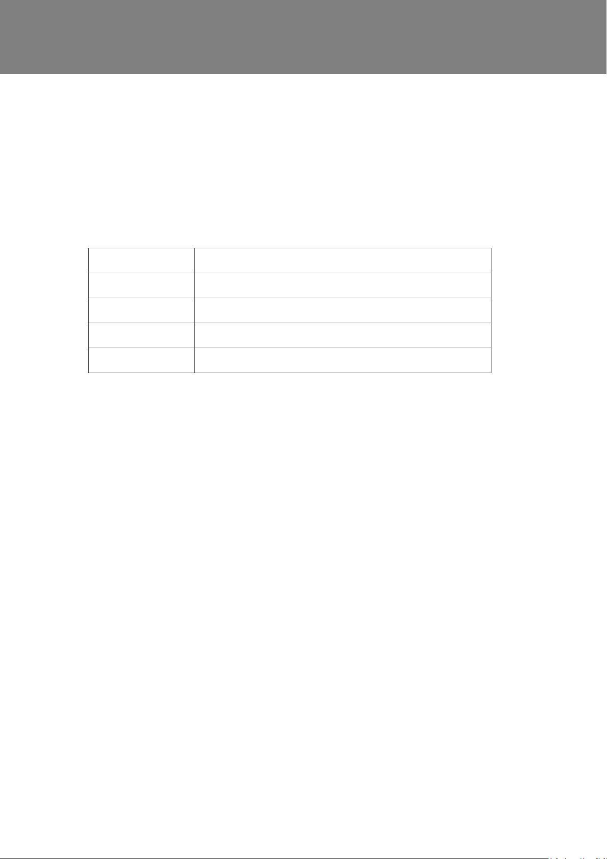
The unit will run on the user selected Mode for 5-hours before
reverting to Normal, unless cancelled
Summer Bypass Mode
The Sentinel Kinetic Advance inclu des a Summer Bypass (SBP) feature to bypass the heat exchanger to
provide cooling when the desired I ndoor Temperature is above the ambi ent temperature.
Note that the volume of air provided by a ventilation system is a fractio n of that required for space heating or
space cooling and will not in itself be sufficient to cool a room. It will however, provide a contribution.
Modes of operation
Bypass Mode Operation
Off Bypass feature is disabled
Normal The unit will run on Normal Mode, unless cancelled
Evening Fresh
Night Time Fresh*
Bypass mode will operate when both the Indoor and Outdoor temperature thresholds are exceeded, and the
outdoor temperature is below the in door temperature.
Indoor Temp: This is the maximum desired indoor temperature. A bove the set indoor temperature the
summer bypass will operate.
Indoor temp should be set, 2-3°C higher than the central heating ther m ostat to prevent the bypass operating
in winter, and 2-3°C lower than any air c onditioning thermostat if fi tt ed.
Outdoor Temp: This is the minimum allowed outdoor air temperatur e. The air temperature must be above this
value for the Bypass to operate, use this value to prevent the bypass operating in winter.
The suggested Outdoor Temp, is 14°C, set as appropriate for your region.
Bypass mode will be cancelled when either:
- The internal air temperature drops below the Indoor Temp threshold, or
- The external air temperature drops b el ow the Outdoor Temp threshold
Note: Pressing the Boost button dur ing Evening Fresh and Night Time fresh operation will revert the unit to
Normal bypass mode.
The unit will run at the user selected Mode, unless cancelled
It is recommended that the user select ed mode chosen for Evening Fresh and Night Time Fresh is higher than
Normal flow rate to reduce the indoor temperature more rapidly.
*Night Time Fresh Mode is intended for use through the night when cooling is a higher priority than any
increase of noise. Note, that the air noise in your system is influenced by flowrate, ducting design, layout and
the size and type of vents used in the rooms. If improvements are required please c ontact your installer.
58 MVHR Installation and User Guide 476930
Page 59
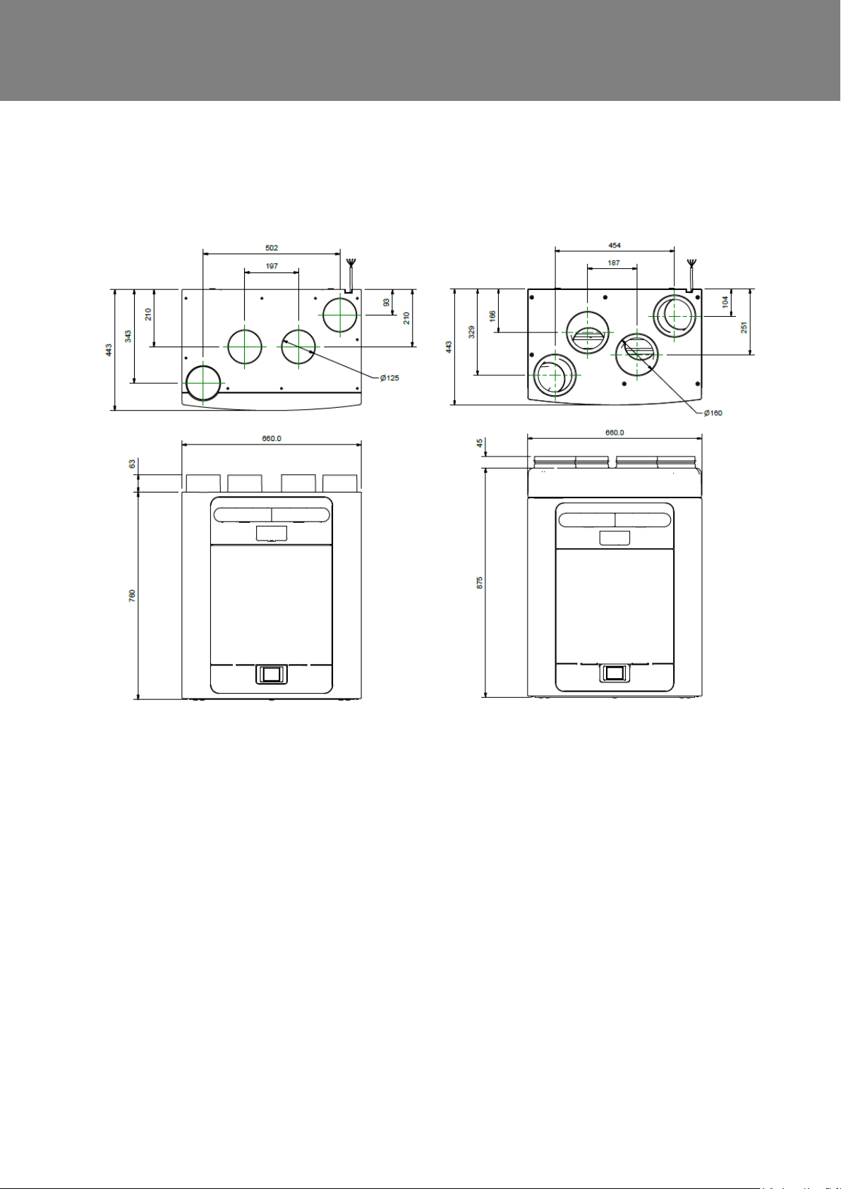
(Label is positioned to the right of the controller).
Product Dimensions
Technical data
Figure 2: Dimensions
Remove front cover (see page 24) to view Rating l abel.
MVHR Installation and User Guide 476930 59
Page 60
Technical data
Spares
The following spare parts may be ordered from Vent-Axia:
Part No Description
472663 Main Power Board
472665 Control Module
472667 Filters G3, 2 per pack
472669 Filters M5, 1 per pack
472671 Filters F7, 1 per pack
472673 Motor Scroll Assembly
472675 Summer Bypass Motor Assembly
472685 Temperature/Humidity Sensor T1 (Right)
472679 Temperature Sensor T2 (Left)
472687 Temperature/Humidity Sensor T3 (Left)
472683 Temperature Sensor T4 (Right)
478335 Constant Volume + Clean Filter Pressure Sensors PCBA
Please note:
If the grade of filter used in the unit is c hanged from what was initially supplied, the performance of the preheater may be
affected. An external preheater may be necessary depending on the specific installation and filter combination.
60 MVHR Installation and User Guide 476930
Page 61

Default settings
Commissioning Screens
Time
Mode Names
Low Supply/Extract
Control Mode
Service Phone
Boost Over-run
LS1/LS2/LS3
Parameters Settings
Country United Kingdom
Language English.
Date Automatic - Factory set
Unit configuration Right Hand
Filter Check 12 months
Summer Bypass Normal
User Mode
Boost Supply/Extract 50 %
Normal Supply/ Extract 30 %
Purge Supply/Extract 100%
Internal RH Mode On
Internal RH Setpoint 70%
Frost Protection Airflow Mode
Mode schedule 1 All days set to 0:00 (on), 00:00 (off) – inactive
Mode Schedule 2 All days set to 0:00 (on). 00:00 (off) – inactive
Set Lock code 0000
Indoor Temp 25 C
Outdoor Temp 14 C
Boost Overrun set time 15
Boost Delay Off
Boost Delay set time 00
SW1/SW2/SW3/SW4/SW5 User Mode 3 (Boost)
Proportional 1/2 Humidity – Boost, Normal (60 %)
Technical data
Automatic GMT/BST - Factory set
Normal, Boost, Low, Purge
20%
Normal
Not Set
Off
User Mode 3 (Boost)
CO2 – Boost (2000 ppm), Normal (1000 ppm)
Temperature – Boost (27ºC, Normal (17ºC)
Table 2 Default settings
The touch screen controller consum es 0.5 Watts in stand-by mode when fitted t o the MVHR unit. If required this controller
may be removed from the unit and stored s eparately, further minimising t he overall energy consumption.
MVHR Installation and User Guide 476930 61
Page 62
Technical data
Name:
Vent-Axia
SEC Class
A+
SEC Value ('Average')
-43.03
SEC Value ('Warm')
-17.88
SEC Value ('Cold')
-87.71
Label Required? (Yes/No=Out of scope)
Yes
Declared as: RVU or NRVU/UVU or BVU
RVU/BVU
Speed Drive
Variable Speed
Type HRS (Recuperative, Regenerative, None)
Recuperative
Thermal Eff: [ (%), NA(if none)]
89
Max. Flow Rate (m3/h)
378
Max. Power Input (W): (@Max.Flow Rate)
190
LWA: Sound Power Level (dB)
56.0
Ref. Flow Rate (m3/s)
0.07350
Ref. Pressure Diff. (Pa)
50
SPI [W/(m3/h)]
0.25
Control Factor & Control Typology: (CTRL/ Typology)
Control Factor; CTRL
0.65
Control Typology
Local Demand Control
(for regenerative heat exchangers only),
-&Ext. Leakage Rates (%) for Ducted UVUs;
connection on either supply or extract air side;
performance and energy efficiency of the unit
For UVUs (Instructions Install Regulated Supply/Extract Grilles Façade)
N/A
Internet Address (for Disassembly Instructions)
www.vent-axia.com
Sensitivity p. Variation@+20/-20 Pa: (for Non-Ducted VUs)
N/A
Air Tightness-ID/OD-(m3/h) (for Non-Ducted VUs)
N/A
Annual Electricity Consumption: AEC (kWh/a) pr. m²
1.75
Annual Heating Saved: AHS (kWh/a) pr. m²
AHS: Average
46.73
AHS: Warm
21.13
AHS: Cold
91.41
Product fiche
Model ID (Stock Ref.) :
405215 Advance S
405216 Advance SX
476808 Advance Sp LH
476809 Advance Sp RH
Declared: -Max Internal & External Leakage Rates(%) for BVUs or carry over
Mixing Rate of Non-Ducted BVUs not intended to be equipped with one duct
Position and description of visual filter warning for RVUs intended for use with
filters, including text pointing out the importance of regular filter changes for
<5% Internal, <5% External
N/A
Refer to User Instructions
62 MVHR Installation and User Guide 476930
Page 63

MVHR Installation and User Guide 476930 63
Page 64
Head Office: Fleming Way, Crawley, West Sussex, RH10 9YX.
EU Authorised Representative: Vent
UK NATIONAL CALL CENTRE
SALES ENQUIRIES:
TECHNICAL SUPPORT
476930N 0521
Disposal
This product should not be disposed of with household waste. Please recycle
where facilities exist. Check with your local authority for recycling advice.
The Guarantee
Applicable only to products installed and used in the United Kingdom. For details of guarantee outside the United Kingdom contact your local
Vent-Axia guarantees its products for two years from date of purchase against faulty material or workmanship. In the event of any part being found
to be defective, the product will be repaired, or at the Company’s option replaced, without charge, provided that the product:-
• Has been installed and used in accordance with the instructions given with each unit.
• Has not been connected to an unsuitable electricity supply. (The correct electricity supply voltage is shown on the product rating label
attached to the unit).
• Has not been subjected to misuse, neglect or damage.
• Has not been modified or repaired by any person not authorised by the company.
IF CLAIMING UNDER TERMS OF GUARANTEE
Please return the complete product, carriage paid to your original supplier or nearest Vent-Axia Centre, by post or personal visit. Please ensure
that it is adequately packed and accompanied by a letter clearly marked “Guarantee Claim” stating the nature of the fault and providing evidence of
date and source of purchase.
The guarantee is offered to you as an extra benefit, and does not affect your legal rights
supplier.
-Axia Bedrijvenweg 17 7442 CX Nijverdal Nederland [email protected]
, Newton Road, Crawley, West Sussex, RH10 9 JA
Tel: 0344 8560590 Fax: 01293 565169
: Tel: 0344 8560594 Fax: 01293 539209
64 MVHR Installation and User Guide 476930
 Loading...