

Page 1
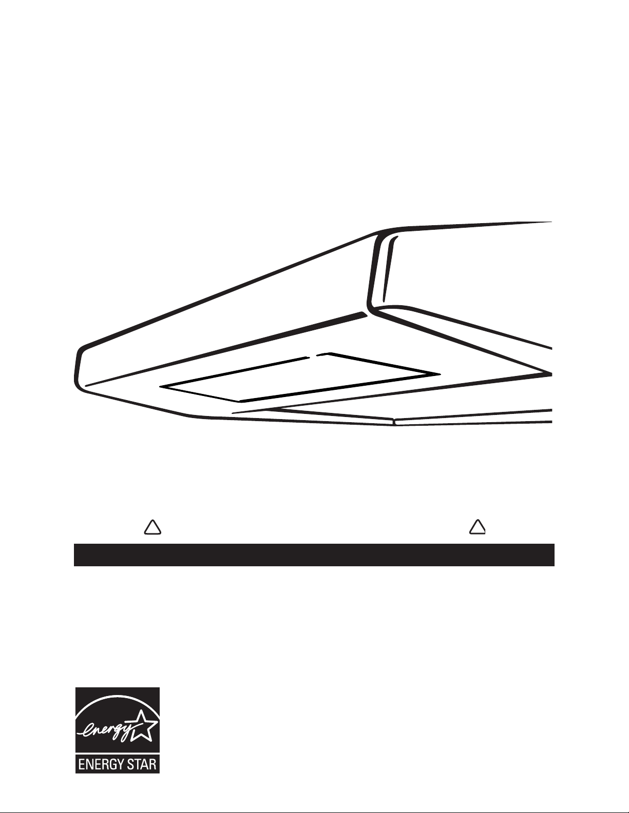
HB0062
RANGE HOOD
INSTALLATION INSTRUCTIONS - USE AND CARE
INTENDED FOR DOMESTIC COOKING ONLY
INSTALLER: LEAVE THIS MANUAL WITH HOMEOWNER.
HOMEOWNER: CLEANING AND OPERATION INFORMATION
ON PAGES 9 AND 10.
SV06727 rev. D
READ AND SAVE THESE INSTRUCTIONS
!
!
MODELS ESB10, QDE, AND ESC270
REGISTER YOUR PRODUCT ON LINE AT: www.venmar.ca
Page 2

WARNING WARNING
- 2 -
TO REDUCE THE RISK OF FIRE, ELECTRIC
SHOCK OR INJURY TO PERSONS, OBSERVE THE
FOLLOWING:
1. Use this unit only in the manner intended by the
manufacturer. If you have questions, contact the
manufacturer at the address or telephone number listed
in the warranty.
2. Before servicing or cleaning unit, switch power off
at service panel and lock service disconnecting means
to prevent power from being switched on accidentally.
When the service disconnecting means cannot be
locked, securely fasten a prominent warning device,
such as a tag, to the service panel.
3. Installation work and electrical wiring must be done by
qualified personnel in accordance with all applicable
codes and standards, including fire-rated construction
codes and standards.
4. Sufficient air is needed for proper combustion and
exhausting of gases through the flue (chimney) of
fuel burning equipment to prevent backdrafting. Follow
the heating equipment manufacturer’s guidelines and
safety standards such as those published by the
National Fire Protection Association (NFPA), and the
American Society for Heating, Refrigeration and Air
Conditioning Engineers (ASHRAE), and the local code
authorities.
5. When cutting or drilling into wall or ceiling, do not
damage electrical wiring and other hidden utilities.
6. Ducted fans must always be vented to the outdoors.
7. Do not use this unit with any solid-state speed control
device.
8. To reduce the risk of fire, use only metal ductwork.
9. This unit must be grounded.
10.
When applicable local regulations comprise more
restrictive installation and/or certification requirements,
the aforementioned requirements prevail on those of
this document and the installer agrees to conform to
these at his own expenses.
TO REDUCE THE RISK OF A RANGE TOP
GREASE FIRE:
a) Never leave surface units unattended at high settings.
Boilovers cause smoking and greasy spillovers that
may ignite. Heat oils slowly on low or medium settings.
b) Always turn hood ON when cooking at high heat
or when cooking flambeing foods (i.e.: crêpes Suzette,
cherries jubilee, peppercorn beef flambé).
c) Clean ventilating fans frequently. Grease should not be
allowed to accumulate on fan or filter.
d) Use proper pan size. Always use cookware appropriate
for the size of the surface element.
TO REDUCE THE RISK OF INJURY TO PERSONS
IN THE EVENT OF A RANGE TOP GREASE FIRE,
OBSERVE THE FOLLOWING*:
1. SMOTHER FLAMES with a close-fitting lid, cookie
sheet or metal tray, then turn off the burner. BE
CAREFUL TO PREVENT BURNS. IF THE FLAMES DO
NOT GO OUT IMMEDIATELY, EVACUATE AND CALL
THE FIRE DEPARTMENT.
2. NEVER PICK UP A FLAMING PAN – You may
be burned.
3. DO NOT USE WATER, including wet dishcloths or
towels – This could cause a violent steam explosion.
4. Use an extinguisher ONLY if:
A. You own a Class ABC extinguisher and you
know how to operate it.
B. The fire is small and contained in the area where
it started.
C. The fire department has been called.
D. You can fight the fire with your back to an exit.
*Based on “Kitchen Fire Safety Tips” published by NFPA.
CAUTION
1. For indoor use only.
2. For general ventilating use only. Do not use to exhaust
hazardous or explosive materials and vapors.
3. To avoid motor bearing damage and noisy and/or
unbalanced impeller, keep drywall spray, construction
dust, etc. off power unit.
4. Your hood motor has a thermal overload which will
automatically shut off the motor if it becomes
overheated. The motor will restart when it will cool
down. If the motor continues to shut off and restart,
have the hood serviced.
5. The minimum hood distance above cooktop must
not be less than 20” for an electric range, and 24” for
a gas range. A maximum of 30” above cooktop is
highly recommended for best capture of cooking
impurities.
6. Two installers are recommended because of the large
size and weight of this hood.
7. To reduce the risk of fire and to properly exhaust
air, be sure to duct air outside – Do not exhaust air into
spaces within walls or ceiling or into attics, crawl space
or garage.
8. Because of the high exhausting capacity of this hood,
you should make sure enough air is entering the house
to replace exhausted air by opening a window close to
or in the kitchen.
9. Use with approved cord-connection kit only.
10. Please read specification label on product for further
information and requirements.
11. All demonstrator range hoods (model numbers ending
by D) are not for sale, unless their original power cord
is removed.
!
!
Page 3

Please take note this manual uses the following symbols to emphasize particular information:
NOTE: Indicates supplementary information needed to fully complete an instruction.
NOTE: Because this publication covers many hood models, the illustrations are typical ones. Some details of your unit may be
slightly different of the ones shown.
ABOUT THIS MANUAL
TOOLS NEEDED TO INSTALL THE RANGE HOOD
WARNING
Identifies an instruction which, if not followed, might cause serious personal injuries including possibility of death.
!
CAUTION
Denotes an instruction which, if not followed, may severely damage the unit and/or its components.
- Phillips screwdriver no. 2 or Robertson no. 1 and no. 2
- Pair of long nose pliers (to open the horizontal or vertical discharge knockout hole)
- Hammer and flat blade screwdriver (to open the electrical knockout hole)
- Sheet metal sheers
- Pair of pliers
- Scissors (to cut duct tape)
- Pen
- Wire stripper
TABLE OF CONTENTS
1. INSTALL DUCTWORK . . . . . . . . . . . . . . . . . . . . . . . . . . . . . . . . . . . . . . . . . . . . . . . . . . . . . . . . . . . . . . . . . . . . 4
2. MEASURE THE INSTALLATION . . . . . . . . . . . . . . . . . . . . . . . . . . . . . . . . . . . . . . . . . . . . . . . . . . . . . . . . . . . . . . . 4
3. PREPARE THE INSTALLATION . . . . . . . . . . . . . . . . . . . . . . . . . . . . . . . . . . . . . . . . . . . . . . . . . . . . . . . . . . . . . . . 5
4. PREPARE THE HOOD . . . . . . . . . . . . . . . . . . . . . . . . . . . . . . . . . . . . . . . . . . . . . . . . . . . . . . . . . . . . . . . . . . 5-6
5. INSTALL THE ADAPTER/DAMPER . . . . . . . . . . . . . . . . . . . . . . . . . . . . . . . . . . . . . . . . . . . . . . . . . . . . . . . . . . . 6-7
6. I
NSTALL THE HOOD . . . . . . . . . . . . . . . . . . . . . . . . . . . . . . . . . . . . . . . . . . . . . . . . . . . . . . . . . . . . . . . . . . . . . 7
7. C
ONNECT WIRING . . . . . . . . . . . . . . . . . . . . . . . . . . . . . . . . . . . . . . . . . . . . . . . . . . . . . . . . . . . . . . . . . . . . . . 7
8. R
EINSTALL BOTTOM PANEL AND FILTERS . . . . . . . . . . . . . . . . . . . . . . . . . . . . . . . . . . . . . . . . . . . . . . . . . . . . . . 8
9. F
LUORESCENT LAMPS . . . . . . . . . . . . . . . . . . . . . . . . . . . . . . . . . . . . . . . . . . . . . . . . . . . . . . . . . . . . . . . . . . . 8
10. CLEANING . . . . . . . . . . . . . . . . . . . . . . . . . . . . . . . . . . . . . . . . . . . . . . . . . . . . . . . . . . . . . . . . . . . . . . . . . . 9
11. O
PERATION . . . . . . . . . . . . . . . . . . . . . . . . . . . . . . . . . . . . . . . . . . . . . . . . . . . . . . . . . . . . . . . . . . . . . . . . . 10
12. SERVICE PARTS . . . . . . . . . . . . . . . . . . . . . . . . . . . . . . . . . . . . . . . . . . . . . . . . . . . . . . . . . . . . . . . . . . . 11-12
- 3 -
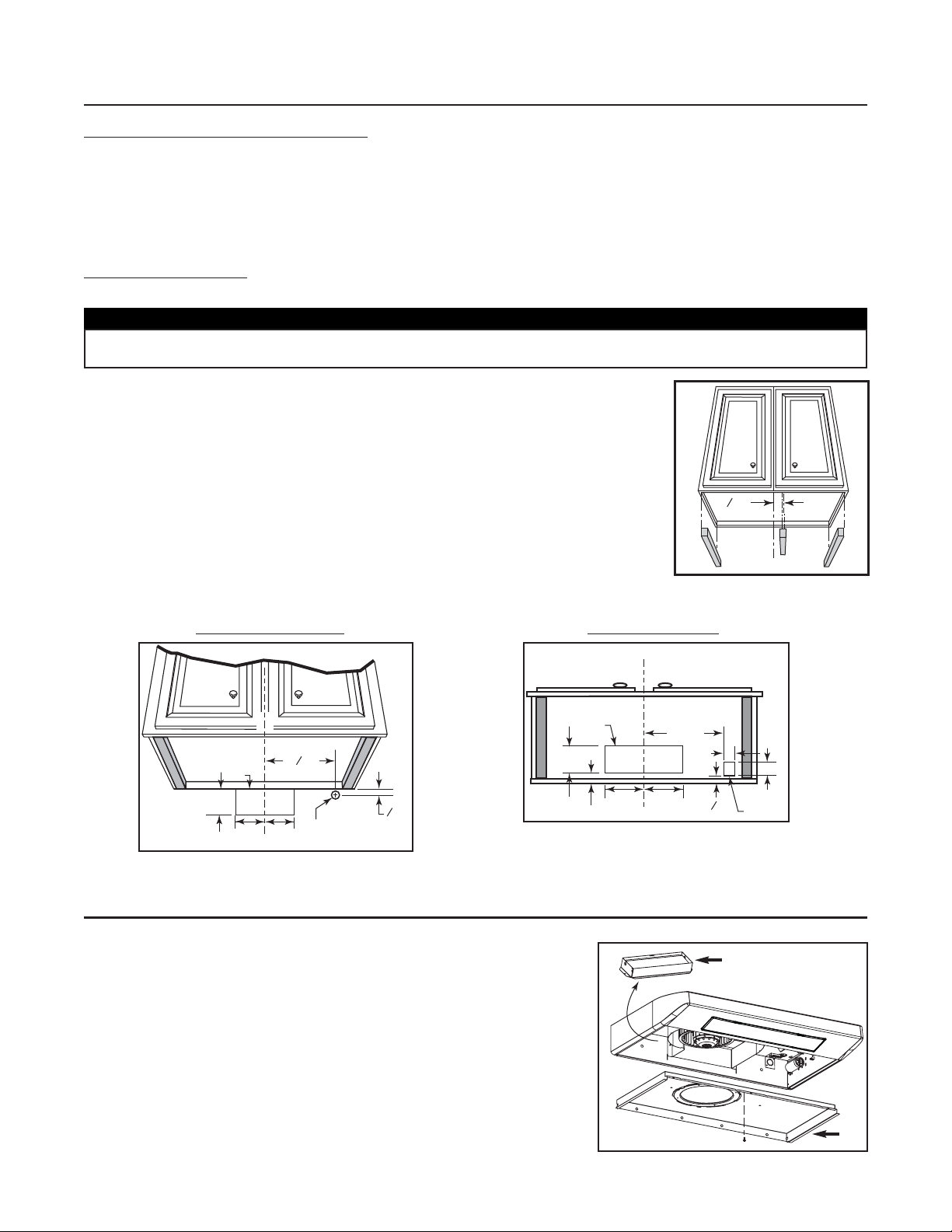
Page 4
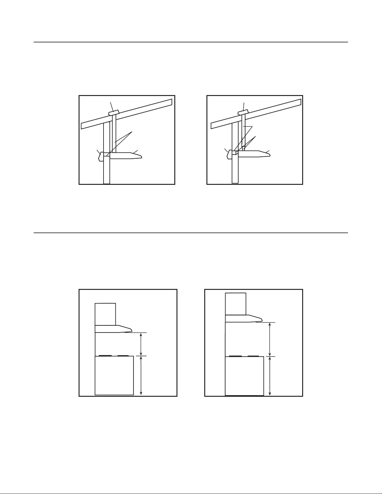
1. INSTALL DUCTWORK
Plan where and how the ductwork will be installed.
Install proper-sized ductwork, elbow(s) and roof or wall cap for the type of blower you are installing. If using 6’’ (150 mm) round
ducts, use a transition. Use 2’’ (50 mm) metal foil duct tape to seal joints.
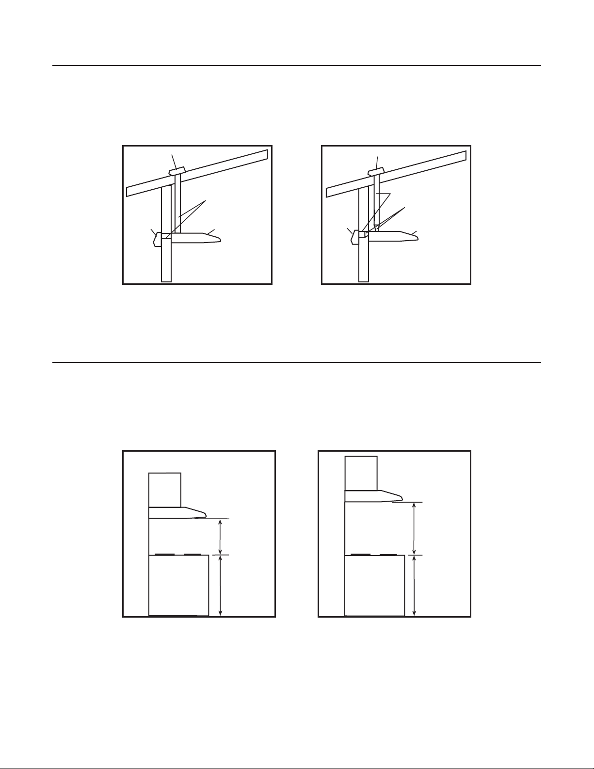
2. MEASURE THE INSTALLATION
Dimensions for the most common installations are shown below.
We recommend to install the hood at a minimum of 20” (508 mm) from an electric range and at 24” (610 mm) from a
gas range.
For optimal performance, the hood should not be installed more than 30” (762 mm) from cooktop.
Cabinets
30” maximum
clearance
Standard
36” height
cooktop
HH0012A
Hood
Cabinets
20” minimum
clearance
(24” for gas)
Standard
36” height
cooktop
HH0013A
Hood
- 4 -
Wall cap
HH0011A
Roof cap
3¼” x 10” duct
Hood
Wall cap
HH0014A
Roof cap
6” round duct
3¼” x 10” to 6”
round transition
Hood
Page 5
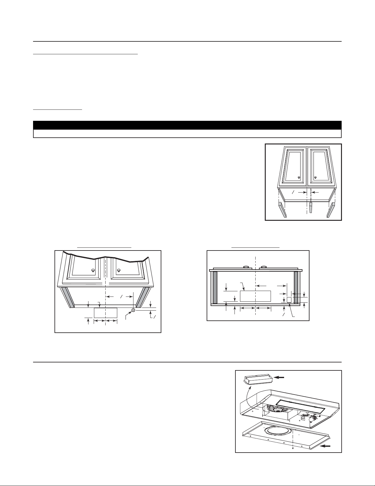
NOTE: If the bottom of the cupboard is recessed, attach wood strips (not included), as shown
beside, in order to properly install the range hood under the cabinet. The wood strips
must be as thick as recess.
Cut-out the openings for duct (A) and power cable (B), in cabinet or wall, according to the direction of discharge chosen.
See figures below.
H
ORIZONTAL DISCHARGE:VERTICAL DISCHARGE:
- 5 -
3. PREPARE THE INSTALLATION
Make sure the following items are included:
- Hood
- Filters (2)
- Adapter/damper assembly 3¼’’ x 10’’ (located inside the hood, under the bottom panel)
- Compact fluorescent lamps (120 V, 13 W, PLC13, 2700 K with G24q-1 base) (packed behind the light diffuser)
- Parts bag (located inside the hood, under the bottom panel) including:
1 wire clamp, 5 no. 8 x 1/2’’ double thread screws, 2 wire connectors and 6 no. 6 x 1/2’’ screws
Part sold separately
:
- Transition 3¼”x 10” to 6” round (optional, for 6” round ducts installation only)
CAUTION
When performing installation, servicing or cleaning the unit, it is recommended to wear safety glasses and gloves.
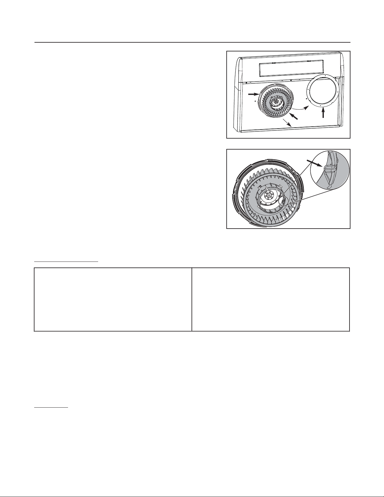
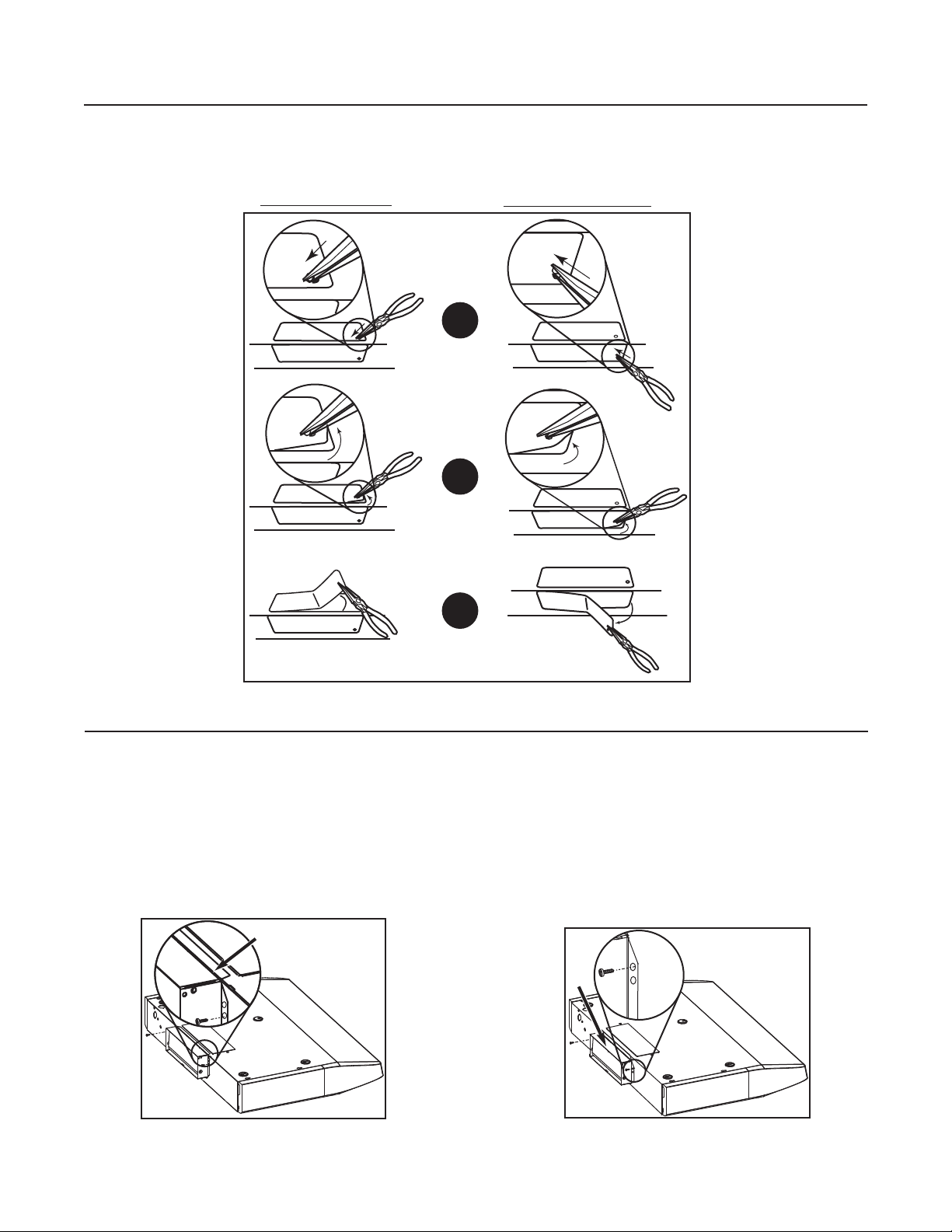
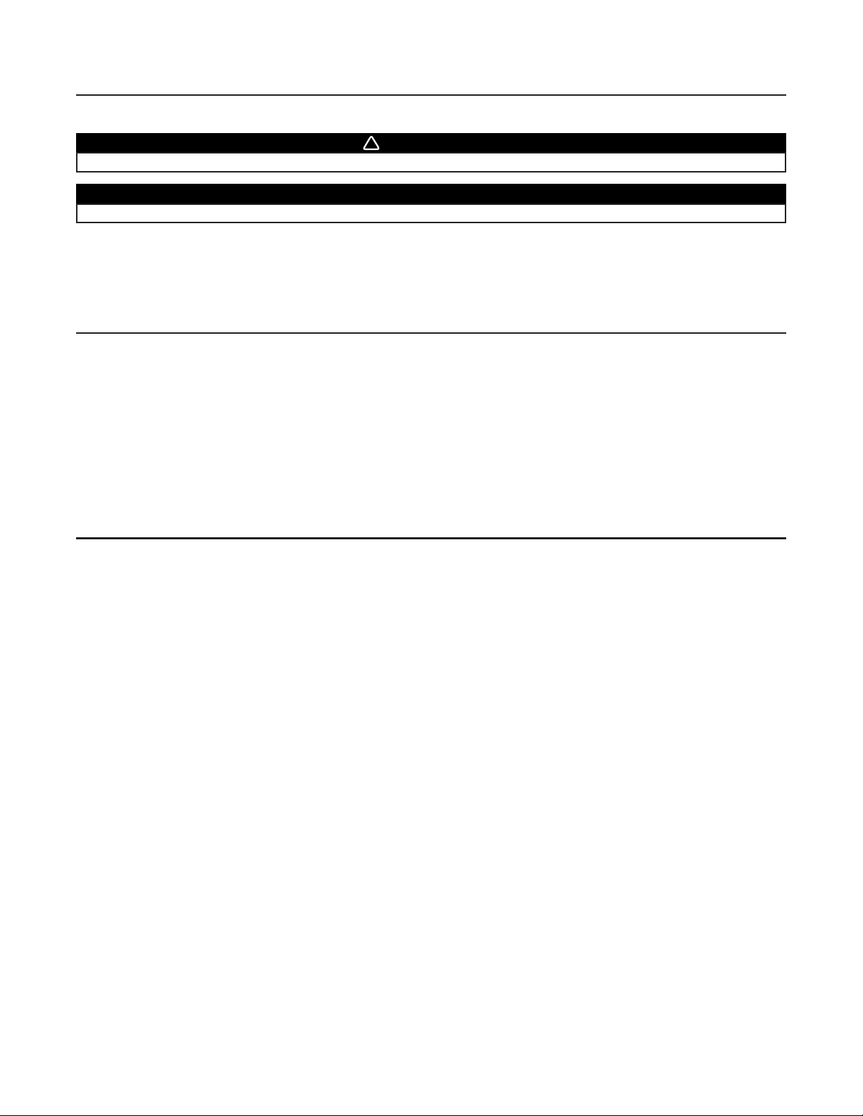
4. PREPARE THE HOOD
Remove both filters from the hood. Disassemble the adapter/damper (A) from the
hood.
NOTE: The adapter/damper is located inside the hood. Remove the bottom panel (B)
to access the adapter/damper. Refer to figure beside.
3
8
2 ”
HO0002A
CABINET BOTTOM
C
L
HD0150A
3½”
C
L
A
5¼” 5¼”
1
”
11
8
B
1¼” dia.
7
”
8
HD0151A
3¾”
A
¾”
5¼” 5¼”
10½”
1 ¼”
1½”
3
”
8
B
A
HO0091
B
Page 6

- 6 -
4. PREPARE THE HOOD (CONT’D)
NOTE: If this hood replaces another one, please note that the location of the air exhaust can vary from one manufacturer to another.
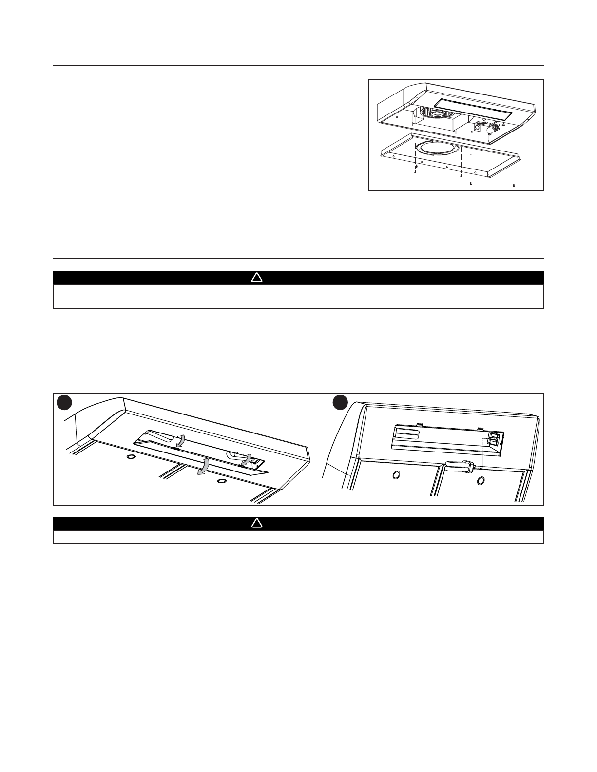
5. INSTALL THE ADAPTER/DAMPER
Fold down the foldable flange (C) of the
adapter/damper. This flange must be at 90° from the
remaining flanges. Use the lower screw holes on
each side of the adapter/damper to assemble it to the
back of hood. See below.
C
It may be necessary to adjust the adapter/damper location
to the existing wall discharge opening. Leave the foldable
flange (C) of the adapter/damper as is. Use the upper
screw holes on each side of the adapter/damper to
assemble it to the back of hood. See below.
C
HORIZONTAL DISCHARGE, NEW INSTALLATION
HORIZONTAL DISCHARGE, HOOD REPLACEMENT
Punch out the appropriate electrical knock-out hole.
Using a long nose pliers, remove the knock-out for the chosen opening (vertical on top or horizontal at the back of the hood).
See figures below.
VERTICAL DISCHARGE
HORIZONTAL DISCHARGE
1
2
3
HD0153
HJ0006
HJ0007
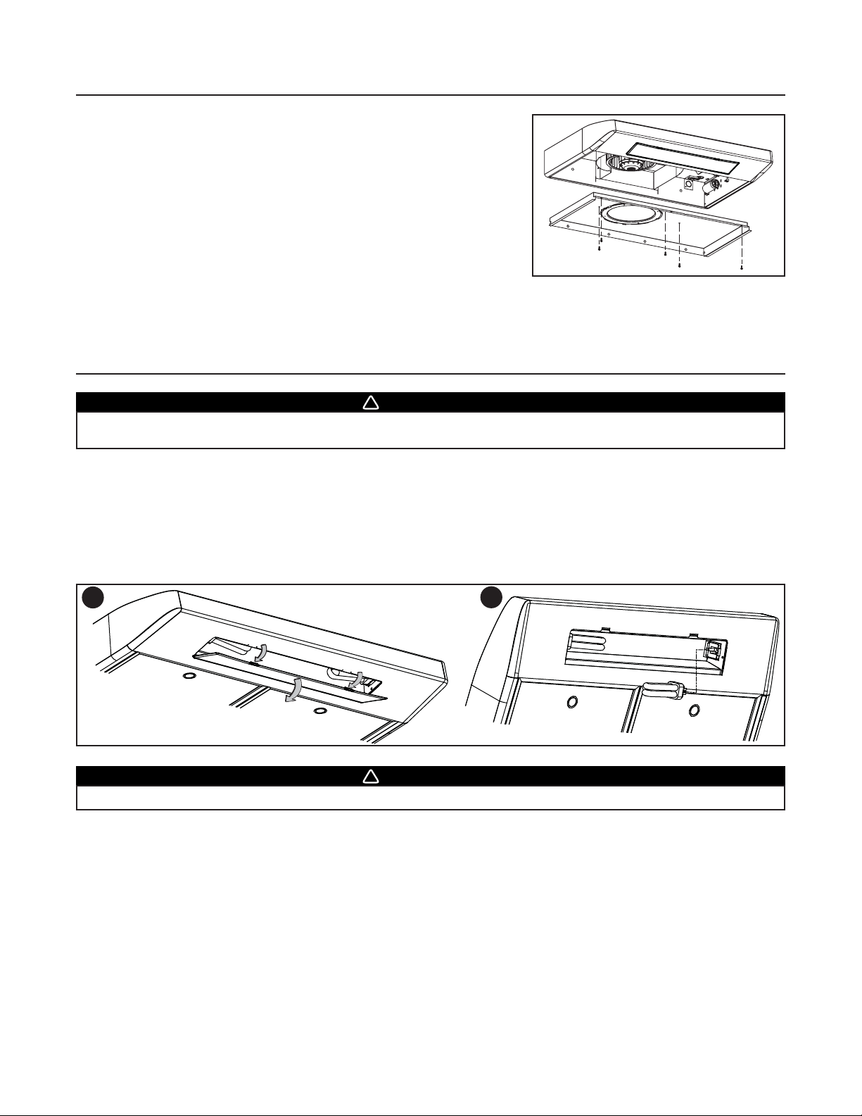
Page 7
- 7 -
NOTES: 1. For the best ventilation performance, if a round duct must be used, the duct diameter must be 6” or more. Use a
3¼” x 10” to 6” round transition.
2. The wall duct must be well prepared to receive the adapter. Before performing the installation, make sure the
adapter fits easily in the duct.
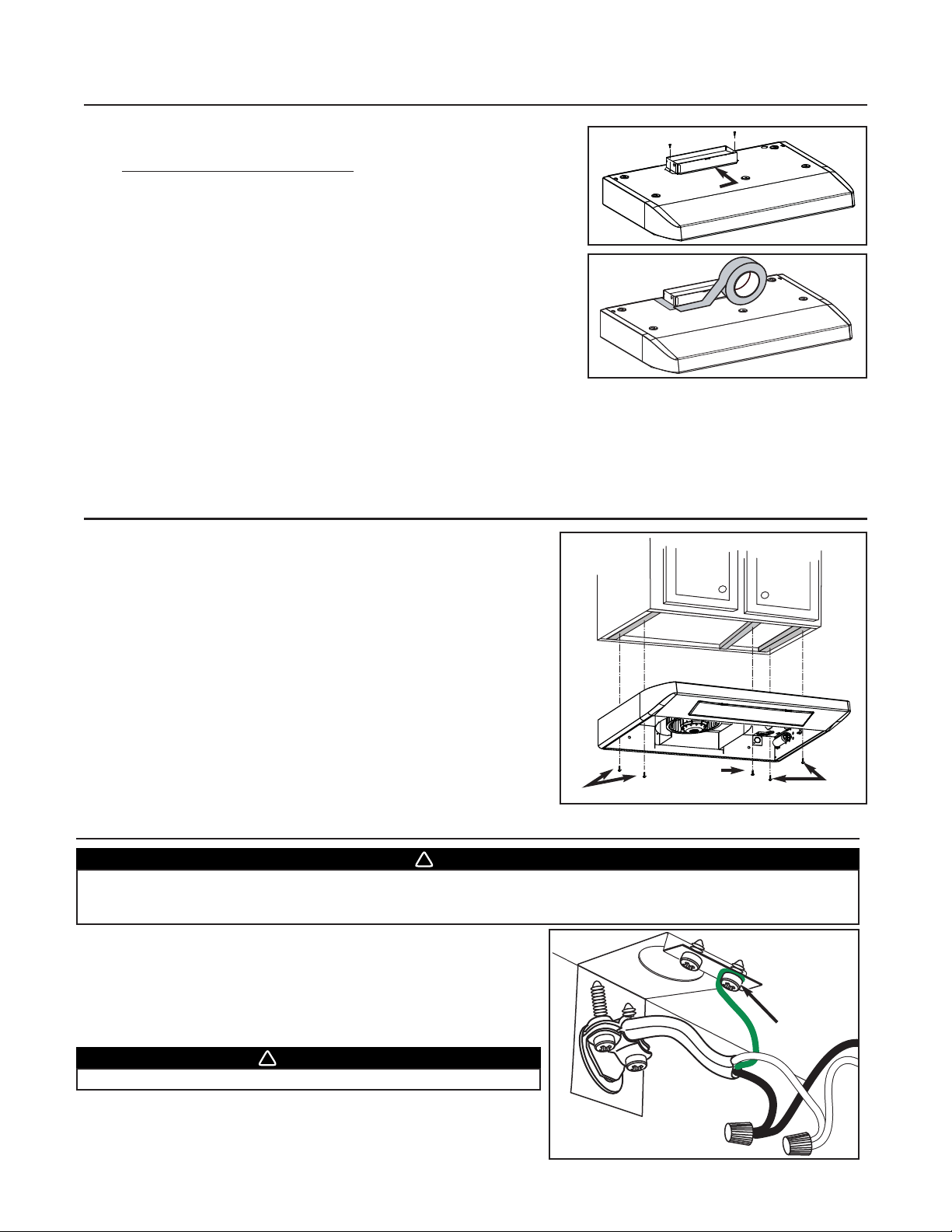
Using two 1/2” screws, secure the adapter/damper to the top or back of the
hood. Seal the adapter/damper to the hood using metal foil duct tape.
6. INSTALL THE HOOD
Run power cable to installation location. Place the hood at its location.
Using a pen, mark the position of the screws (smaller part of the
embossed keyholes). Remove the hood and install four 1/2” double thread
screws at sides locations (A), leaving a 1/8” gap. Place the wire clamp,
insert the cable in the hood and tighten the wire clamp to secure the cable.
Place the hood under the cabinet and slide it in position. Make sure the
adapter/damper assembly enters the ducting and the damper opens freely.
Secure the hood by tightening the screws completely. Install the last 1/2”
double thread screw (B) in the remaining embossed hole.
5. INSTALL THE ADAPTER/DAMPER (CONT’D)
For a vertical discharge installation only, leave the foldable flange (C) of the
adapter/damper as is. This flange must be located towards the front of the hood.
See beside.
C
VERTICAL DISCHARGE
ALL INSTALLATIONS
Connect cable to range hood wiring using included wire connectors.
Connect BLACK to BLACK, WHITE to WHITE and GREEN or BARE WIRE
to GREEN ground screw (1).
WARNING
Risk of electrical shock. Electrical wiring must be done by qualified personnel in accordance with all applicable codes
and standards. Before connecting wires, switch power off at service panel and lock service disconnecting means to
prevent power to be switched on accidentally.
!
7. CONNECT WIRING
HE0059
WARNING
Do not forget to connect the ground!
!
1
A
A
B
HO0057
HO0058
HD0217
Page 8

- 8 -
8. REINSTALL BOTTOM PANEL AND FILTERS
Reinstall the bottom panel, using the retaining screw previously removed in
step 4 plus 4 others from parts bag. Refer to illustration beside.
Then, reinstall filters.
9. FLUORESCENT LAMPS
WARNING
This hood has fluorescent lamps containing mercury. Dispose of appropriately, according to local laws and requirements.
!
This range hood must use compact fluorescent lamps (120 V, 13 W, PLC13, 2700 K with G24q-1 base) (included).
NOTE: The range hood is shipped with both fluorescent lamps packed behind the light diffuser.
1. To access fluorescent lamps, remove the light diffuser by pushing on its both tabs and pulling it down.
2. To install the fluorescent lamps, slide their 4 prongs into their corresponding holes in their socket until secured. Reinstall the
light diffuser.
WARNING
In order to prevent the risk of personal injury, the fluorescent lamps must be cooled down before removing them.
!
To remove fluorescent lamps, remove the light diffuser and pull fluorescent lamps out of their socket.
NOTE: Some fluorescent lamps may produce a yellowish lighting on first usages. This temporary effect will disappear out in
time by itself.
HO0092
1
HO0099
2
Page 9
- 9 -
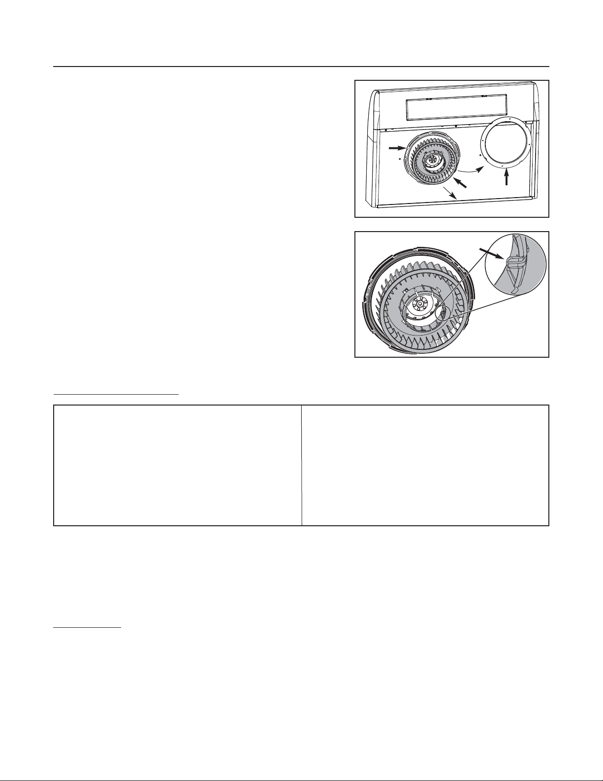
10. CLEANING
The grease filters, bottom panel, intake ring (A) and blower wheel (B) should
be cleaned frequently. Use a warm detergent solution. The grease filters,
intake ring and blower wheel are dishwasher safe.
Clean all-metal filters in the diswasher using a non-phosphate detergent.
Discoloration of the filter may occur if using phosphate detergents, or as a
result of local water conditions — but this will not affect filter performance.
This discoloration is not covered by the warranty.
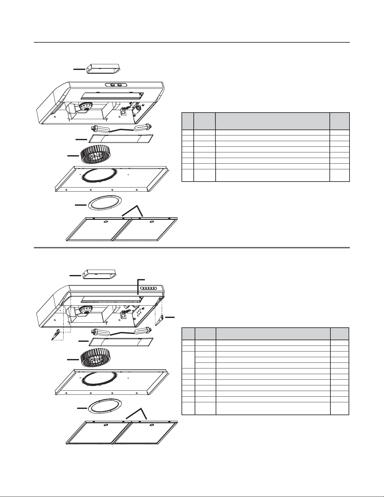
To remove the blower wheel, first take off its intake ring. Then remove the
blower wheel by pulling it down smoothly.
NOTE: Do not try to remove the black part (C) attached to the bottom panel.
When reinstalling the blower wheel, make sure the small tab (D) will fit into
one hole of the motor.
A
C
B
Do:
• Regularly wash surfaces with clean cloth or rag soaked
with warm water and mild soap or liquid dish detergent.
• Always clean in the direction of original polish lines.
• Always rinse well with clear water (2 or 3 times) after
cleaning. Wipe completely dry.
• You may also use a specialized household stainless steel
cleaner.
Don’t:
• Use any steel or stainless steel wool or any other scrapers
to remove stubborn dirt.
• Use any harsh or abrasive cleansers.
• Allow dirt to accumulate.
• Let plaster dust or any other construction residues reach
the hood. During construction or renovation, cover the hood
to make sure no dust adheres to stainless steel surface.
Avoid: when choosing a detergent
- Any cleaners that contain bleach will attack stainless steel.
- Any products containing: chloride, fluoride, iodide, bromide will deteriorate surfaces rapidly.
-Any combustible products used for cleaning such as acetone, alcohol, ether, benzol, etc., are highly explosive and should
never be used close to a range.
E
NAMEL FINISH:
Clean with warm water and mild detergent only. If discoloration occurs, use a good enamel polish such as automotive polish.
(DO NOT use rough abrasive cleaner or porcelain cleaner.)
S
TAINLESS STEEL CLEANING:
HD0221
HD0156
D
Page 10

- 10 -
11. OPERATION
Always turn on the hood before beginning cooking in order to establish an air flow in the kitchen. Let the blower run for a few
minutes to clear the air after turning off the range.
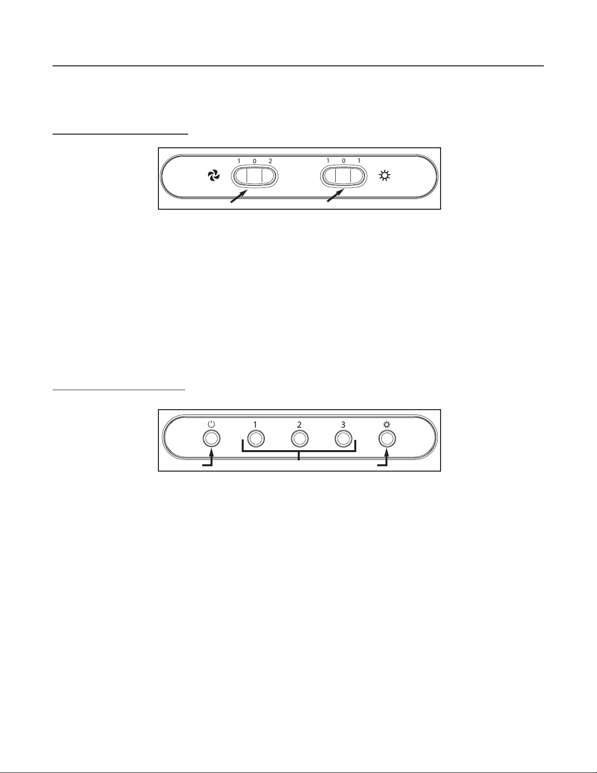
ROCKER SWITCH CONTROL
A. ON/OFF BLOWER AND SPEED CONTROL SWITCH:
This 3-position rocker switch controls the blower speed. Pressing on left side (1) will result in low speed operation, while
pressing on right side (2) will turn on the blower to high speed. To stop the blower operation, set the rocker switch to the
central position (0).
B. ON/OFF L
IGHTING CONTROL SWITCH:
This 3-position rocker switch controls the lighting. Press either on left side (1) or right side (1) to obtain full lighting.
To shut off the lights, set the rocker switch to the central position (0).
A
B
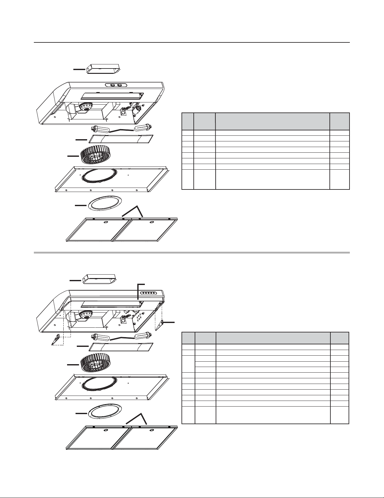
MECHANICAL PUSH-BUTTON CONTROL
A. OFF BLOWER SWITCH:
Press on this switch to stop the blower operation.
B. S
PEED BLOWER SWITCHES:
Press on left switch (1) to turn on the blower on low speed, on middle switch (2) to turn on the blower on medium speed, and
on right switch (3) to turn on the blower on high speed.
C ON/OFF L
IGHTING SWITCH:
Press on this switch to turn on the fluorescent lights, and press again to turn them off.
A
BC
HC0031
HC0021
Page 11
- 11 -
KEY PART DESCRIPTION QTY.
No. No.
1 13296 ADAPTER/DAMPER 1
2 03623 F
LUORESCENT LAMP 2
3 01752 L
IGHT DIFFUSER 1
4 01988 B
LOWER WHEEL 1
5 01757 I
NLET RING 1
6 14131 M
ICROMESH FILTER (THE PAIR)1
* SV06727 I
NSTALLATION & USER MANUAL 1
*
H
ARDWARE BAG: (1) WIRE CLAMP, (2) WIRE CONNECTORS,
04281
(6)
NO. 6 X 1/2” SCREWS, (5) NO. 8 X 1/2” DOUBLE THREAD SCREWS
1
12. SERVICE PARTS
*Not shown
2
4
1
5
3
6
KEY PART
No. No. DESCRIPTION QTY.
1 13296 ADAPTER/DAMPER 1
2 16153 S
MOKED GLASS 1
16150 G
LASS HOLDER BLACK (PA I R)1
3 16151 G
LASS HOLDER WHITE (PA IR )1
16152 GLASS HOLDER GREY (PA I R )1
4 03623 F
LUORESCENT LAMP 2
5 01752 L
IGHT DIFFUSER 1
6 01988 B
LOWER WHEEL 1
7 01757 I
NLET RING 1
8 14131 M
ICROMESH FILTER (THE PAIR)1
* SV06727 I
NSTALLATION & USER MANUAL 1
* 04281
H
ARDWARE BAG: (1) WIRE CLAMP, (2) WIRE CONNECTORS
1
(6)
NO. 6 X 1/2” SCREWS, (5) NO. 8 X 1/2” DOUBLE THREAD SCREWS
1
3
7
8
2
5
6
4
*Not shown
MODEL ESC270
MODEL ESB10
HL0092
HL0093
Page 12

- 12 -
KEY PART
No. No. DESCRIPTION QTY.
1 SV13296 A
DAPTER/DAMPER 1
2
SV15434 R
OCKER SWITCH WHITE (PA I R) + OVERLAY WHITE 1
SV15433 R
OCKER SWITCH BLACK (PA I R) + OVERLAY BLACK 1
3 SV03623 F
LUORESCENT LAMP 2
4 SV01752 L
IGHT DIFFUSER 1
5 SV01765 M
OTOR 1
6 SV01988 B
LOWER WHEEL 1
7
SV16119 B
OTTOM PAN WHITE 1
SV16117 B
OTTOM PAN BLACK 1
8 SV01757 INLET RING 1
9 SV14131 M
ICROMESH FILTER (THE PAIR)1
10 SV02104 S
ECONDARY CAPACITOR 7.5 µF 1
11 SV06756 C
APACITOR 11.5 µF 1
12 SV03649 B
ALLAST HARNESS (SOCKET LAMPS INCLUDED)1
* SV06727 INSTALLATION & USER MANUAL 1
* SV04281
H
ARDWARE BAG: (1) WIRE CLAMP, (2) WIRE CONNECTORS
1
(6)
NO. 6 X 1/2” SCREWS, (5) NO. 8 X 1/2” DOUBLE THREAD SCREWS
12. SERVICE PARTS
*Not shown
MODEL QDE
1
2
3
4
5
6
7
8
9
10
12
11
HL0095
Page 13

HOTTES DE CUISINIÈRE
DIRECTIVES D’INSTALLATION,
D’UTILISATION ET D’ENTRETIEN
CONÇUES UNIQUEMENT POUR LA CUISSON DOMESTIQUE
INSTALLATEUR : LAISSEZ CE GUIDE AU PROPRIÉTAIRE.
PROPRIÉTAIRE : DIRECTIVES D’ENTRETIEN ET DE FONCTIONNEMENT
EN PAGES 21 et 22.
SV06727 rév. D
VEUILLEZ LIRE ET CONSERVER CES DIRECTIVES
!
!
MODÈLES ESB10, QDE ET ESC270
ENREGISTREZ VOTRE PRODUIT EN LIGNE À : www.venmar.ca
HB0062
Page 14

- 14 -
AVERTISSEMENT AVERTISSEMENT
AFIN DE RÉDUIRE LES RISQUES D’INCENDIE,
D’ÉLECTROCUTION OU DE BLESSURES CORPORELLES,
SUIVEZ LES DIRECTIVES SUIVANTES :
1. N’utilisez cet appareil que de la façon prévue par le
manufacturier. Si vous avez des questions, contactez le
manufacturier à l’adresse et au numéro de téléphone
indiqués sur la garantie.
2. Avant de nettoyer ou de réparer l’appareil, coupez
le courant au panneau d’alimentation et verrouillez-en
l’accès afin d’éviter sa remise en marche accidentelle.
Si le panneau d’alimentation ne peut être verrouillé,
y fixer un indicateur voyant comme, par exemple, une
étiquette de couleur vive.
3. Les travaux d’installation et de raccordement électrique
doivent être effectués par du personnel qualifié,
conformément aux codes et standards de construction,
incluant ceux concernant la prévention des incendies.
4. Une circulation d’air efficace est requise afin d’assurer
la combustion et l’évacuation complète des gaz par la
cheminée des équipements à combustion, afin de
prévenir les retours de cheminée. Conformez-vous
aux instructions et aux standards de sécurité des
manufacturiers d’équipement de chauffage, tels que
publiés par le
National Fire Protection Association
(NFPA), et l’
American Society for Heating, Refrigeration
and Air Conditioning Engineers
(ASHRAE), ainsi que
les responsables des codes locaux.
5. Lorsque vous coupez ou perforez un mur ou un plafond,
prenez garde de ne pas endommager les fils électriques
ou autre installation qui pourrait y être dissimulés.
6. Les conduits de l’installation doivent toujours rejeter
l’air à l’extérieur.
7. Ne pas utiliser cet appareil avec une autre commande
de vitesse à semi-conducteur.
8. Afin de réduire les risques d’incendie, n’utilisez que des
conduits en métal.
9. Cet appareil doit être relié à une mise à la terre.
10. Lorsqu’une réglementation est en vigueur localement et
qu’elle comporte des exigences d’installation et/ou de
certification plus restrictives, lesdites exigences
prévalent sur celles de ce document et l’installateur
entend s’y conformer à ses frais.
AFIN DE RÉDUIRE LES RISQUES DE FEU
DE CUISINIÈRE :
a) Ne jamais laisser les appareils de cuisson sans
surveillance lorsqu’ils sont réglés à feu vif. Les
débordements engendrent de la fumée et des
déversements graisseux pouvant s’enflammer.
Chauffez l’huile lentement, à feu doux ou moyen.
b) Mettez toujours la hotte en marche lorsque vous
cuisinez à feu vif ou que vous cuisinez des mets flambés (par ex. : crêpes Suzette, cerises jubilé, steak au
poivre flambé).
c) Nettoyez régulièrement la roue du ventilateur. Ne laissez
pas la graisse s’accumuler sur le ventilateur ou les filtres.
d) Utilisez le bon format de casserole. Servez-vous toujours
de casseroles et d’ustensiles appropriés à la dimension
de la surface chauffante.
AFIN D’ÉVITER TOUS RISQUES DE BLESSURE
DANS LE CAS D’UN FEU DE CUISINIÈRE, SUIVEZ
CES DIRECTIVES* :
1. ÉTOUFFEZ LES FLAMMES avec un couvercle
hermétique, une tôle à biscuits ou un plateau
métallique, et ensuite éteindre le brûleur. PRENEZ
SOIN D’ÉVITER LES BRÛLURES. SI LES FLAMMES
NE S’ÉTEIGNENT PAS IMMÉDIATEMENT, ÉVACUEZ
LES LIEUX ET APPELER LES POMPIERS.
2. NE PRENEZ JAMAIS UNE CASSEROLE EN
FLAMMES DANS VOS MAINS. – Vous pourriez subir
des brûlures.
3. N’UTILISEZ PAS D’EAU, incluant linges à vaisselle ou
serviettes mouillés – ceci pourrait occasionner une
violente explosion de vapeur.
4. N’utilisez un extincteur QUE DANS LE CAS OÙ :
A. Vous savez qu’il s’agit d’un extincteur de classe ABC
et que vous en connaissez le fonctionnement.
B. L’incendie est petit et limité à l’endroit où il a débuté.
C. Les pompiers ont été avisés.
D. Vous pouvez combattre l’incendie en ayant accès
à une sortie de secours.
*Tirées du
Kitchen Fire Safety Tips
publié par la NFPA.
ATTENTION
1. Pour une utilisation à l’intérieur seulement.
2. Pour usage de ventilation générale seulement. Ne
pas utiliser pour évacuer des vapeurs ou des produits
dangeureux ou explosifs.
3. Afin d’éviter tout dommage au moteur et de débalancer
ou de rendre bruyante la roue du moteur, gardez votre
appareil à l’abri des poussières de gypse et de
construction/rénovation, etc.
4. Le moteur de votre hotte possède une protection
thermique qui éteindra automatiquement le moteur s’il
devient surchauffé. Le moteur repartira automatiquement
une fois refroidi. Si le moteur continue à arrêter et à
repartir, faites-le vérifier.
5. Pour une meilleure évacuation des odeurs de cuisine,
le bas de votre hotte devrait être à un minimum de 20 po
au-dessus d’une cuisinière électrique (24 po au-dessus
d’une cuisinière à gaz) et à un maximum de 30 po
au-dessus de la surface de cuisson.
6. Deux installateurs sont recommandés lors de
l’installation en raison de la grande dimension et du
poids de cet appareil.
7. Afin de réduire les risques d’incendie, assurez-vous
d’évacuer l’air à l’extérieur. Ne pas évacuer l’air
dans des espaces clos comme l’intérieur des murs ou
plafond, ou dans le grenier, faux-plafond ou garage.
8. À cause de la grande capacité d’évacuation de cet
appareil, il est recommandé d’ouvrir une fenêtre dans
une pièce dans ou près de la cuisine afin de remplacer
l’air évacué.
9. Cette hotte ne doit être utilisée qu’avec un ensemble
de cordon d’alimentation approuvé.
10. Veuillez consulter l’autocollant apposé à l’intérieur du
produit pour plus d’informations ou autres exigences.
11. Toutes les hottes de démonstration (ayant un n° de
modèle se terminant par D) ne peuvent être vendues, à
moins que leur cordon d’alimentation d’origine ne
soit retiré.
!
!
Page 15
- 15 -
Ce guide utilise les symboles suivants afin d’accentuer les informations qui s’y trouvent :
NOTE : Indique une information supplémentaire afin de réaliser complètement une instruction.
NOTE : En raison du nombre de modèles couverts par cette publication, les illustrations qui s’y trouvent sont typiques. Certains
détails de votre hotte peuvent être légèrement différents de ceux démontrés.
À PROPOS DE CE GUIDE
OUTILS NÉCESSAIRES À L’INSTALLATION DE LA HOTTE
AVERTISSEMENT
Identifie une instruction qui, si elle n’est pas suivie, peut causer de graves blessures corporelles ou la mort.
!
ATTENTION
Identifie une instruction qui, si elle n’est pas suivie, peut gravement endommager l’appareil et/ou ses pièces.
- Un tournevis Phillips n° 2 ou Robertson n° 1 et n° 2
- Une pince à long bec (pour dégager le trou d’évacuation horizontale ou verticale)
- Un marteau et un tournevis à lame plate (pour dégager le trou d’accès à l’alimentation électrique)
- Des ciseaux à tôle
- Des pinces
- Des ciseaux (pour couper le ruban adhésif de métal)
- Une pince à dénuder
- Un crayon
TABLE DES MATIÈRES
1. INSTALLATION DES CONDUITS . . . . . . . . . . . . . . . . . . . . . . . . . . . . . . . . . . . . . . . . . . . . . . . . . . . . . . . . . . . . . 16
2. MESURESDEL’INSTALLATION . . . . . . . . . . . . . . . . . . . . . . . . . . . . . . . . . . . . . . . . . . . . . . . . . . . . . . . . . . . . . 16
3. PRÉPARATION DE L’INSTALLATION . . . . . . . . . . . . . . . . . . . . . . . . . . . . . . . . . . . . . . . . . . . . . . . . . . . . . . . . . . . 17
4. PRÉPARATION DE LA HOTTE . . . . . . . . . . . . . . . . . . . . . . . . . . . . . . . . . . . . . . . . . . . . . . . . . . . . . . . . . . . . 17-18
5. INSTALLATION DE L’ADAPTATEUR/VOLET . . . . . . . . . . . . . . . . . . . . . . . . . . . . . . . . . . . . . . . . . . . . . . . . . . . . .18-19
6. I
NSTALLATION DE LA HOTTE . . . . . . . . . . . . . . . . . . . . . . . . . . . . . . . . . . . . . . . . . . . . . . . . . . . . . . . . . . . . . . . 19
7. BRANCHEMENT . . . . . . . . . . . . . . . . . . . . . . . . . . . . . . . . . . . . . . . . . . . . . . . . . . . . . . . . . . . . . . . . . . . . . . . 19
8. R
ÉINSTALLATION DU PANNEAU INFÉRIEUR . . . . . . . . . . . . . . . . . . . . . . . . . . . . . . . . . . . . . . . . . . . . . . . . . . . . . 20
9. LAMPES FLUORESCENTES . . . . . . . . . . . . . . . . . . . . . . . . . . . . . . . . . . . . . . . . . . . . . . . . . . . . . . . . . . . . . . . .20
10. E
NTRETIEN . . . . . . . . . . . . . . . . . . . . . . . . . . . . . . . . . . . . . . . . . . . . . . . . . . . . . . . . . . . . . . . . . . . . . . . . . 21
11. FONCTIONNEMENT . . . . . . . . . . . . . . . . . . . . . . . . . . . . . . . . . . . . . . . . . . . . . . . . . . . . . . . . . . . . . . . . . . . . 22
12. PIÈCES DE REMPLACEMENT . . . . . . . . . . . . . . . . . . . . . . . . . . . . . . . . . . . . . . . . . . . . . . . . . . . . . . . . . . . 23-24
Page 16
- 16 -
1. INSTALLATION DES CONDUITS
Planifier à quel endroit et de quelle façon seront installés les conduits.
Installer des conduits de format adéquat, coude(s) et capuchon de mur ou de toit selon le genre de ventilateur utilisé. Si des
conduits ronds de 6 po (150 mm) sont utilisés, se servir d’une transition. Sceller les joints avec du ruban adhésif en toile de
2 po (50 mm) de largeur.
Hotte
Conduits de
3¼ po x 10 po
Capuchon de toit
Capuchon
de mur
HH0011F
2. MESURES DE L’INSTALLATION
Voici les dimensions pour les installations les plus courantes.
Il est recommandé d’installer la hotte à une distance minimale de 20 po (508 mm) au-dessus d’une cuisinière électrique
et de 24 po (610 mm) au-dessus d’une cuisinière à gaz.
Pour des performances optimales, la hotte ne doit jamais être installée à plus de 30 po (762 mm) au-dessus de la table de cuisson.
Armoires
Distance
maximale
de 30 po
HH0012F
Hotte
Cuisinière
standard
de 36 po
de hauteur
Armoires
Distance
minimale de 20 po
(24 po pour une
cuisinière à gaz)
Cuisinière
standard
de 36 po
de hauteur
HH0013F
Hotte
Capuchon de toit
Conduit rond de 6 po
Transition de
3¼ po x 10 po
Capuchon
de mur
HH0014F
à 6 po ronde
Hotte
Page 17
NOTE : Si le fond de l’armoire est en retrait, fixer des baguettes de bois (non incluses) aux
emplacements prévus pour les vis d’assemblage de la hotte (A). Les baguettes de
bois doivent être de la même épaisseur que la profondeur du retrait. Voir ci-dessous.
Selon le type d’évacuation choisie, découper, dans l’armoire ou le mur, les ouvertures pour les conduits (A) et le fil d’alimentation
électrique (B). Voir les illustrations ci-dessous.
É
VACUATION HORIZONTALE ÉVACUATION VERTICALE
- 17 -
3. PRÉPARATION DE L’INSTALLATION
S’assurer que les articles suivants sont inclus :
- Hotte
- Filtres (2)
- Adaptateur/volet 3¼ po x 10 po (à l’intérieur de la hotte, sous le panneau inférieur)
- Ampoules fluorescentes compactes (120 V, 13 W, PLC13, 2700 K avec culot G24q-1) (emballées derrière le diffuseur lumière)
- Sac de pièces (à l’intérieur de la hotte, sous le panneau inférieur) incluant :
1 serre-fils, 5 vis à double filets n° 8 x 1/2, 2 capuchons de connexion et 6 vis n° 6 x 1/2 po
Pièce vendue séparément
:
- Transition 3¼ po x 10 po à 6 po ronde (optionnelle, pour une installation avec conduits ronds de 6 po seulement).
ATTENTION
Il est recommandé de porter des lunettes et des gants de sécurité lors de l’installation, de l’entretien ou de la
réparation de cet appareil.
Retirer les deux filtres de la hotte. Désassembler l’adaptateur/volet (A) de la hotte.
NOTE : L’adaptateur/volet se situe à l’intérieur de la hotte. Le panneau inférieur (B)
doit être retiré pour accéder à l’adaptateur/volet. Voir l’illustration ci-contre.
4. PRÉPARATION DE LA HOTTE
3
8
2 po
HO0002F
DESSOUS DE L’ARMOIRE
C
L
3¾ po
A
5¼ po 5¼ po
¾ po
10½ po
1¼ po
1½ po
3
po
8
B
HD0150F
3½ po
A
5¼ po
C
L
11
5¼ po
1
po
8
B
1¼ po dia.
7
po
8
HD0151F
A
HO0091
B
Page 18
- 18 -
4. PRÉPARATION DE LA HOTTE (SUITE)
5. INSTALLATION DE L’ADAPTATEUR/VOLET
NOTE : Si cette hotte en remplace une autre, prendre note que la localisation de la sortie d’air peut varier d’un manufacturier à l’autre.
Plier le rebord pliable (C) de l’adaptateur/volet. Ce rebord
doit être à 90° par rapport aux autres. Assembler
l’adaptateur/volet à l’arrière de la hotte en insérant les vis
d’assemblage dans le trou inférieur des 2 rebords.
Voir ci-dessous.
C
Il peut être nécessaire d’ajuster l’emplacement de
l’adaptateur/volet à l’ouverture existante pour l’évacuation
par le mur. Pour ce faire, laisser le rebord pliable (C) de
l’adaptateur/volet tel quel. Assembler l’adaptateur/volet à
l’arrière de la hotte en insérant les vis d’assemblage dans
le trou supérieur des 2 rebords.
Voir ci-dessous.
C
ÉVACUATION HORIZONTALE, NOUVELLE INSTALLATION
ÉVACUATION HORIZONTALE, REMPLACEMENT D’UNE HOTTE
Défoncer l’ouverture préamorcée prévue pour le fil d’alimentation électrique.
À l’aide d’une pince à long bec, retirer l’overture préamorcée choisie (évacuation verticale sur le dessus ou horizontale à
l’arrière de la hotte). Voir les illustrations ci-dessous.
É
VACUATION VERTICALE
ÉVACUATION HORIZONTALE
1
2
3
HD0153
HJ0006
HJ0007
Page 19

- 19 -
6. INSTALLATION DE LA HOTTE
Passer le fil d’alimention électrique jusqu’à l’emplacement de la hotte. Placer
la hotte à son emplacement. À l’aide d’un crayon, marquer la position des
vis (petite partie des trous embossés en forme de serrure). Retirer la hotte
et visser quatre vis 1/2 po à double filets aux emplacements latéraux (A), en
laissant un espace de 1/8 po. Installer le serre-fils à la hotte, y insérer le cordon
d’alimentation et serrer le serre-fils pour le maintenir en place. Placer la
hotte sous l’armoire et la glisser en position. S’assurer que l’adaptateur/volet
entre dans le conduit et que son volet ouvre librement. Visser complètement
les vis pour maintenir la hotte en position. Visser la dernière vis 1/2 po à
double filets (B) dans le dernier trou embossé.
A
A
B
NOTE : Pour obtenir la meilleure performance en ventilation, si un conduit rond
doit être utilisé, le diamètre de ce conduit doit être de 6 po ou plus.
Utiliser une transition 3¼ po x 10 po à 6 po ronde. Le conduit mural doit
être bien préparé pour recevoir l’adaptateur. Avant d’effectuer
l’installation, s’assurer que l’adaptateur s’insère bien dans le conduit.
Pour une installation avec évacuation verticale seulement
, laisser le rebord
pliable (C) tel quel. Installer l’adaptateur/volet de façon à ce que ce rebord soit
dirigé vers l’avant de la hotte. Voir ci-contre.
C
TOUTES LES INSTALLATIONS
À l’aide de deux vis 1/2 po, fixer l’adaptateur/volet sur le dessus ou à l’arrière de
la hotte. Sceller l’adaptateur/volet à la hotte à l’aide de ruban adhésif de métal.
ÉVACUATION VERTICALE
5. INSTALLATION DE L’ADAPTATEUR/VOLET (SUITE)
Connecter les fils à la hotte en utilisant les connecteurs fournis.
Connecter le NOIR au NOIR, le BLANC au BLANC et le VERT ou FIL
DÉNUDÉ à la vis VERTE de mise à la terre (1).
AVERTISSEMENT
Risque d’électrocution. Le raccordement électrique doit être effectué par du personnel qualifié conformément aux
codes et standards. Avant d’effectuer le branchement, coupez l’alimentation électrique au tableau de distribution
principal et verrouillez-le pour éviter une mise en marche accidentelle.
!
7. BRANCHEMENT
AVERTISSEMENT
Ne pas oublier de connecter la mise à la terre!
!
HE0059
1
HO0057
HO0058
HD0217
Page 20
- 20 -
Pour enlever les lampes fluorescentes, retirer le diffuseur lumière et tirer sur les lampes pour les dégager de la hotte.
NOTE : Certaines lampes fluorescentes peuvent produire un éclairage jaunâtre au début de leur utilisation. Cet effet
temporaire disparaîtra de lui-même avec le temps.
9. LAMPES FLUORESCENTES
AVERTISSEMENT
Cette hotte a des lampes fluorescentes qui contiennent du mercure. Se défaire de ces lampes de façon appropriée,
selon les lois et règlements locaux.
!
8. RÉINSTALLATION DU PANNEAU INFÉRIEUR
Réinstaller le panneau inférieur et le fixer à la hotte à l’aide de la vis retirée
précédemment à l’étape 4 plus quatre autres provenant du sac de pièces.
Voir ci-contre.
Puis, réinstaller les filtres.
Cette hotte utilise des ampoules fluorescentes compactes de 120 V, 13 W, PLC13, 2700 K avec culot G24q-1 (incluses).
NOTE : La hotte est livrée avec ses 2 lampes fluorescentes emballées derrière son diffuseur lumière.
1. Pour accéder aux lampes fluorescentes, retirer le diffuseur lumière en poussant sur les languettes et en tirant vers le
bas, tel qu’il est illustré.
2. Pour installer les lampes fluorescentes, insérer leurs 4 broches dans leur trous correspondants dans leur réceptacle.
Remettre en place le diffuseur lumière.
AVERTISSEMENT
Afin de réduire le risque de blessures personnelles, attendre que l’ampoule fluorescente soit refroidie avant de la retirer.
!
HO0092
1
HO0099
2
Page 21
- 21 -
À éviter lors du choix d’un détergent :
- Tous produits nettoyants qui contiennent des agents de blanchiment; ils attaqueront l’acier inoxydable.
- Tous produits contenant du chlorure, fluorure, iode ou bromure; ils détérioreront rapidement les surfaces.
- Tous produits combustibles utilisés pour le nettoyage : acétone, alcool, éther, benzène, etc.; ils sont hautement explosifs
et ne devraient jamais être utilisés près d’une cuisinière.
S
URFACES PEINTES :
Nettoyer avec de l’eau chaude additionnée de détergent doux seulement. S’il y a décoloration, utiliser une bonne cire à
peinture telle qu’une cire automobile. (NE PAS utiliser de nettoyant abrasif ou de nettoyant à porcelaine.)
10. ENTRETIEN
Les filtres, le panneau inférieur, l’anneau d’admission (A) et la roue (B) de
ventilateur doivent être nettoyés régulièrement. Utiliser de l’eau chaude
additionnée de détergent. Les filtres, anneau et roue de ventilateur sont
lavables au lave-vaisselle.
Nettoyer les filtres métalliques au lave-vaisselle avec un détergent sans
phosphate. L’utilisation d’un détergent avec phosphates, de même que la
teneur en minéraux de l’eau, peut occasionner une décoloration des filtres,
ce qui n’affectera en rien leur capacité de filtration. Cette décoloration n’est
pas couverte par la garantie.
Pour retirer la roue du ventilateur, enlever d’abord l’anneau d’admission,
puis dégager la roue du ventilateur en tirant doucement vers le bas.
NOTE : Ne pas tenter de retirer la pièce noire (C) fixée au panneau inférieur.
Lors de la réinsertion de la roue sur son ventilateur, s’assurer que son ergot (D)
entre dans l’un des trous du moteur.
À faire :
• Laver régulièrement les surfaces à l’aide d’un chiffon ou
linge propre imbibé d’eau tiède et de savon doux ou
détergent à vaisselle.
• Toujours nettoyer dans le sens des lignes de grain (sens
du polissage).
• Toujours bien rincer à l’eau propre (2 ou 3 fois) après le
nettoyage et essuyer complètement.
• Un nettoyant domestique conçu spécialement pour l’acier
inoxydable peut aussi être utilisé.
À ne pas faire :
• Utiliser une laine d’acier ou d’acier inoxydable ou tout
autre grattoir pour enlever la saleté tenace.
• Utiliser une poudre nettoyante abrasive ou rugueuse.
• Laisser la saleté s’accumuler.
• Laisser la poussière de plâtre ou tout autre résidu de
construction atteindre la hotte. Couvrir la hotte pour la
durée des travaux afin de s’assurer qu’aucune poussière
n’atteigne la hotte.
A
C
B
NETTOYAGE DE L’ACIER INOXYDABLE :
HD0221
D
HD0156
Page 22

- 22 -
Toujours mettre en marche la hotte avant de commencer la cuisson afin d’établir une circulation d’air dans la cuisine. Aussi,
laisser la hotte fonctionner quelques minutes après l’arrêt de la cuisinière afin de nettoyer l’air.
COMMANDE À INTERRUPTEURS À BASCULE
A. INTERRUPTEUR MARCHE/ARRÊT ET CONTRÔLE DE LA VITESSE :
Cet interrupteur à bascule à trois positions contrôle la vitesse du ventilateur. Pour obtenir la basse vitesse, appuyer sur
son côté gauche (1) et sur son côté droit (2) pour la haute vitesse. Pour arrêter le ventilateur, régler l’interrupteur à bascule
en position centrale (0).
B. I
NTERRUPTEUR MARCHE/ARRÊT D’ÉCLAIRAGE :
Cet interrupteur à bascule à trois positions contrôle l’éclairage. Appuyer sur son côté gauche ou droit (1) pour allumer
les lumières. Pour éteindre la lumière, régler l’interrupteur à bascule en position centrale (0).
COMMANDE À BOUTONS-POUSSOIRS MÉCANIQUES
A. INTERRUPTEUR ARRÊT DU VENTILATEUR :
Appuyer sur cet interrupteur pour faire cesser le fonctionnement du ventilateur.
B. I
NTERRUPTEURS DE VITESSE DU VENTILATEUR :
Appuyer sur l’interrupteur de gauche (1) pour obtenir la basse vitesse, sur celui du centre (2) pour la vitesse moyenne,
et sur l’interrupteur de droite (3) pour obtenir la vitesse maximale.
C. I
NTERRUPTEUR D’ÉCLAIRAGE MARCHE/ARRÊT :
Appuyer sur cet interrupteur pour allumer les lumières, et appuyer une autre fois pour les éteindre.
11. FONCTIONNEMENT
A
B
A
BC
HC0031
HC0021
Page 23

- 23 -
12. PIÈCES DE REMPLACEMENT
N° PIÈCE DESCRIPTION QTÉ
Réf. N°
1 13296 ADAPTATEUR/VOLET 1
2 03623 L
AMPE FLUORESCENTE 2
3 01752 D
IFFUSEUR LUMIÈRE 1
4 01988 R
OUE DE VENTILATEUR 1
5 01757 A
NNEAU D’ADMISSION 1
6 14131 F
ILTRE «MICROMESH » (LA PAIRE)1
* SV06727 G
UIDE D’INSTALLATION ET D’UTILISATION 1
* 04281
S
AC DE PIÈCES : (1) SERRE-FILS, (2) CONNECTEURS DE FILS,
1
(6)
VIS N° 6 X 1/2 PO , (5) VIS À DOUBLE FILETS N° 8 X 1/2 PO
*Non illustré
2
4
1
5
3
6
N° PIÈCE
Réf. N° DESCRIPTION QTÉ
1 13296 ADAPTATEUR/VOLET 1
2 16153 V
ERRE FUMÉ 1
16150 S
UPPORT DE VERRE NOIR (LA PAIRE)1
3 16151 SUPPORT DE VERRE BLANC (LA PAIRE)1
16152 S
UPPORT DE VERRE GRIS (LA PAIRE)1
4 03623 L
AMPE FLUORESCENTE 2
5 01752 D
IFFUSEUR LUMIÈRE 1
6 01988 R
OUE DE VENTILATEUR 1
7 01757 A
NNEAU D’ADMISSION 1
8 14131 F
ILTRE « MICROMESH » (LA PAIRE)1
* SV06727 G
UIDE D’INSTALLATION ET D’UTILISATION 1
* 04281
S
AC DE PIÈCES : (1) SERRE-FILS, (2) CONNECTEURS DE FILS
1
(6)
VIS N° 6 X 1/2 PO, (5) VIS À DOUBLE FILETS N° 8 X 1/2 PO
1
3
7
8
2
5
6
4
*Non illustré
MODÈLE ESC270
MODÈLE ESB10
HL0092
HL0093
Page 24

- 24 -
12. PIÈCES DE REMPLACEMENT
MODÈLE QDE
N° PIÈCE
Réf. N°. DESCRIPTION QTÉ
1 SV13296 A
DAPTATEUR/VOLET 1
2
SV15434 I
NTERRUPTEUR À BASCULE BLANC (PA I RE ) + DÉCALQUE BLANC 1
SV15433 I
NTERRUPTEUR À BASCULE NOIR (PA I RE ) + DÉCALQUE NOIR 1
3 SV03623 L
AMPE FLUORESCENTE 2
4 SV01752 D
IFFUSEUR LUMIÈRE 1
5 SV01765 M
OTEUR 1
6 SV01988 R
OUE DE VENTILATEUR 1
7
SV16119 P
ANNEAU INFÉRIEUR BLANC 1
SV16117 P
ANNEAU INFÉRIEUR NOIR 1
8 SV01757 ANNEAU D’ADMISSION 1
9 SV14131 F
ILTRE « MICROMESH » (LA PAIRE)1
10 SV02104 C
ONDENSATEUR SECONDAIRE 7,5 µF 1
11 SV06756 C
ONDENSATEUR 11,5 µF 1
12 SV03649 H
ARNAIS DES BALLASTS (RÉCEPTACLE DES LAMPES INCLUS)1
* SV06727 GUIDE D’INSTALLATION ET D’UTILISATION 1
* SV04281
S
AC DE PIÈCES : (1) SERRE-FILS, (2) CONNECTEURS DE FILS
1
(6)
VIS N° 6 X 1/2 PO, (5) VIS À DOUBLE FILETS N° 8 X 1/2 PO
*Non illustré
1
2
3
4
5
6
7
8
9
10
12
11
HL0095
Page 25

CAMPANAS DE COCINA
INSTRUCCIONES DE INSTALACIÓN -
UTILIZACIÓN Y CUIDADO
EXCLUSIVAMENTE PARA COCINAS DOMÉSTICAS
INSTALADOR: ENTREGUE ESTE MANUAL AL PROPIETARIO DE LA CASA.
PROPIETARIO: INFORMACIÓN SOBRE LIMPEIZA Y FUNCIONAMIENTO
EN LAS PÁGINAS 33 y 34.
SV06727 rev. D
LEA Y CONSERVE ESTAS INSTRUCCIONES
!
!
MODELOS ESB10, QDE Y ESC270
REGISTRE SU PRODUCTO EN LÍNEA EN: www.venmar.ca
HB0062
Page 26

- 26 -
ADVERTENCIA ADVERTENCIA
PARA REDUCIR EL RIESGO DE INCENDIO,
DESCARGA ELÉCTRICA O LESIÓN CORPORAL,
RESPETE LAS SIGUIENTES INDICACIONES:
1. Utilice este aparato únicamente de la forma en que
indica el fabricante. Si tiene cualquier pregunta, póngase
en contacto con el fabricante en la dirección o el teléfono
que aparecen en la garantía.
2. Antes de reparar o limpiar el aparato, apáguelo en el
tablero de servicio y bloquee los medios de
desconexión para impedir que la corriente se conecte
accidentalmente. Cuando no se pueda bloquear los
medios de desconexión, coloque un dispositivo de
advertencia visible (como una etiqueta) en el tablero
de servicio.
3. La instalación y la conexión elécrica deben ser
realizadas por personal competente de acuerdo con
todos los códigos y normas aplicables, incluso los
relativos a la construcción ignífuga.
4. Para lograr una combustión adecuada y una extracción
correcta de los gases a través de la salida del humo
(chimenea) del equipo quemador de combustible evitando así el contratiro - es necesario disponer de
aire suficiente. Siga las directrices del fabricante del
equipo de material térmico y las normas de seguridad,
como las que publica la NFPA (asociación de protección
contra los incendios) y la ASHRAE (sociedad
estadounidenses de técnicos de calefacción, refrigeración
y aire acondicionado), así como los códigos de los
organismos responsables locales.
5. Al cortar o perforar la pared o el techo, procure no dañar
el cableado eléctrico ni otras instalaciones ocultas.
6. Los ventiladores entubados deben tener salida siempre
al exterior.
7. No utilice este aparato con ningún ostro dispositivo
de control de velocidad con semiconductores.
8. Para reducir el riesgo de incendio, utilice soló
tuberías metálicas.
9. Este aparato debe conectarse a tierra.
10. Cuando una reglamentación local esta en vigor y
conlleva exigencias de instalación y/o de certificación
mas estrictas, susodichas exigencias prevalecen
sobre aquellas en este documento y el instalador
acepta someterse a estas exigencias a sus gastos.
PARA REDUCIR EL RIESGO DE QUE ARDA LA
GRASA EN LA PARTE SUPERIOR DE LA COCINA:
a) No deje nunca recipientes de cocina a fuego vivo sin
vigilancia. Los desbordamientos producen humo y
derrames grasiendos que pueden inflamarse.
Caliente el aceite despacio, a fuego lento o mediano.
b) Ponga ne marcha siempre la campana extractora al
cocinar a temperaturas elevadas o al cocinar alimentos
flamadeos (crepas Suzette, cerezas jubilee, res con
pimienta flambeada).
c) Limpie los ventiladores con frecuencia. No deje que la
grasa se acumule en el ventilador ni en los filtros.
d) Utilice cacerolas de tamaño apropiado. Emplee siempre
un recipiente adecuado para el tamaño de la placa.
PARA REDUCIR EL RIESGO DE LESIONES
CORPORALES EN EL CASO DE QUE ARDA LA
GRASA EN LA PARTE SUPERIOR DE LA COCINA,
SIGA ESTAS INDICACIONES*:
1. SOFOQUE LAS LLAMAS con un tapa ajustada, una hoja
o bandeja metálica para hornear galletas, y apague
luego el quemador. TENGA CUIDADO PARA EVITAR
QUEMADURAS. SI LAS LLAMAS NO SE APAGAN
INMEDIATAMENTE, EVACUE EL LUGAR Y LLAME
A LOS BOMBEROS.
2. NO SUJETE NUNCA UN RECIPIENTE EN LLAMAS
ya que podría quemarse.
3. NO USE AGUA, ni trapos húmedos. Podría causar
una violenta explosión de vapor.
4. Utilice un extintor SOLAMENTE si:
A. Tiene un extintor de tipo ABC y sabe usarlo.
B. El incendio es pequeño y está circunscrito a la
zona empezó.
C. Ya ha llamado a los bomberos.
D. Puede tratar de apagar el fuego si dispone siempre
de una salida detrás de usted.
*Fuente: “Kitchen Fire Safety” Tips publicado por la NFPA.
PRECAUCIÓN
1. Sólo para una utilización en el interior.
2. Sólo para ventilación general. No debe utilizarse para
extraer materiales o vapores peligrosos o exlosivos.
3. Para evitar daños en el cojinete del motor y que la hélice
haga ruido o se desequilibre, mantenga la unidad de
alimentación lejos de los vaporizadores de pirca, del
polvo de la construcción, etc.
4. El motor de la campana tiene un dispositivo contra
sobrecargas térmicas que apaga el motor automáticamente
si éste se sobrecalieta. El motor volverá a ponerse en
marcha cuando se enfríe. Si el motor sigue apagándose
y encendiéndose, haga examinar la campana.
5. La distancia mínima entre la campana y la superficie
de la cocina no debe ser inferior a 20 pulgadas, si se
trata de una cocina eléctica, o de 24 pulgadas, si se trata
de una cocina a gas. Se aconseja encarecidamente
una distancia máxima de 30 pulgadas para que la
campana capte mejor las impurezas que se desprenden
al cocinar.
6. Dado el peso y el tamaño de esta campana, se aconseja
que la instalen dos personas.
7. Para reducir los riesgos de incendio y extraer el aire
debidamente, el aire debe evacuarse fuera. No
extraiga el aire a espacios situados entre las paredes,
en el techo o en el desván, falso techo o garaje.
8. Dada la gran capacidad extractora de esta campana,
debería asegurarse de que en la casa entra suficiente
aire para sustituir el aire extraído. Abra para ello una
ventana en la cocina o cerca de ella.
9. Utilíce sólo con un conjunto autorizado de conexión
con cordón.
10. Para mayor información y conocer los requisitos, lea
la etiqueta con las especificaciones en el producto.
11. Todas las campanas de demonstración (con un n.
o
de
modelo terminace con D) no son se vende a no ser
que se haga retirar el cable eléctrico original.
!
!
Page 27
- 27 -
Tenga en cuenta que este manual se emplean los siguientes símbolos cuando se quiere insistir en una información determinada:
NOTA: Da información complementaria para realizar una instrucción.
NOTA: Dado el número de modelos de los que trata este manual, las ilustraciones don de carácter general. Algunos detalles
de su campana pueden ser ligeramente distintos de los que se muestran aquí.
ÀCERCA DE ESTE MANUAL
HERRAMIENTS NECESARIAS PARA INSTALAR LA CAMPANA
ADVERTENCIA
Se refiere a una instrucción que, de no seguirse, podría causar heridas corporales graves e incluso la muerte.
!
PRECAUCIÓN
Se refiere a una instrucción que, de no seguirse, podría dañar gravemente el aparato o sus piezas.
- Destornillador Phillips n.° 2 o Robertson n.° 1 y n.° 2
- Un par de alicates de punta (para abrir el orificio ciego de descarga horizontal o vertical)
- Un martillo y un destornillador de punta plana (para abrir el orificio ciego eléctrico)
- Revestimiento de chapa metálica (soló para instalaciones con conductos, para ajustarlos)
- Un par de alicates (soló para instalaciones con conductos, para ajustarlos)
- Tijeras (para cortar la cinta para conductos)
- Bolígrafo
- Un par de alicates paraquitar la funda de los hilos eléctricos
ÍNDICE
1. INSTALACIÓN DE LOS TUBOS . . . . . . . . . . . . . . . . . . . . . . . . . . . . . . . . . . . . . . . . . . . . . . . . . . . . . . . . . . . . . . 28
2. DIMENSIONES DE LA INSTALACIÓN . . . . . . . . . . . . . . . . . . . . . . . . . . . . . . . . . . . . . . . . . . . . . . . . . . . . . . . . . . 28
3. PREPARACIÓN DE LA INSTALACIÓN . . . . . . . . . . . . . . . . . . . . . . . . . . . . . . . . . . . . . . . . . . . . . . . . . . . . . . . . . . 29
4. PREPARACIÓN DE LA CAMPANA . . . . . . . . . . . . . . . . . . . . . . . . . . . . . . . . . . . . . . . . . . . . . . . . . . . . . . . . . 29-30
5. INSTALACIÓN DEL ADAPTADOR/DISPOSITIVO DE CIERRE . . . . . . . . . . . . . . . . . . . . . . . . . . . . . . . . . . . . . . . . . .30-31
6. I
NSTALACIÓN DE LA CAMPANA . . . . . . . . . . . . . . . . . . . . . . . . . . . . . . . . . . . . . . . . . . . . . . . . . . . . . . . . . . . . . 31
7. CONEXIÓN DEL CABLEADO . . . . . . . . . . . . . . . . . . . . . . . . . . . . . . . . . . . . . . . . . . . . . . . . . . . . . . . . . . . . . . . 31
8. R
EINSTALACIÓN DEL TABLERO INFERIOR . . . . . . . . . . . . . . . . . . . . . . . . . . . . . . . . . . . . . . . . . . . . . . . . . . . . . . 32
9. BOMBILLAS HALÓGENAS . . . . . . . . . . . . . . . . . . . . . . . . . . . . . . . . . . . . . . . . . . . . . . . . . . . . . . . . . . . . . . . . . 32
10. L
IMPIEZA . . . . . . . . . . . . . . . . . . . . . . . . . . . . . . . . . . . . . . . . . . . . . . . . . . . . . . . . . . . . . . . . . . . . . . . . . . 33
11. FUNCIONAMIENTO . . . . . . . . . . . . . . . . . . . . . . . . . . . . . . . . . . . . . . . . . . . . . . . . . . . . . . . . . . . . . . . . . . . . 34
12. PIEZAS . . . . . . . . . . . . . . . . . . . . . . . . . . . . . . . . . . . . . . . . . . . . . . . . . . . . . . . . . . . . . . . . . . . . . . . . . 35-36
Page 28

- 28 -
1. INSTALACIÓN DE LOS TUBOS
Planifique el lugar y la forma en que se instalarán los tubos.
Instale tubos, codo(s) y tapa de techo o de pared de tamaños adecuados, según el ventilador que vaya a usar. Si utiliza tubos
circulares de 6 pulgadas (150 mm), debería usar un cambio de sección. Utilice cinta adhesiva metálica para tubos de
2 pulgadas (50 mm) para obturar las juntas de los tubos.
2. DIMENSIONES DE LA INSTALACIÓN
Más adelante se muetran las dimensiones para las instalaciones habituales.
Aconsejamos que la campana se instale a una distancia mínima de 20 pulgadas (508 mm) de la superficie de una cocina
eléctrica y de 24 pulgadas (610 mm) de una cocina a gas.
Para lograr un rendimiento óptimo, la campana no debería instalarse a más de 30 pulgadas (762 mm) de la superficie de la cocina.
Armarios
30” de
separación
como máximo
HH0012E
Campana
Cocina
estándar
de 36”
de altura
Armarios
20” de separación
al menos (24” si la
cocina es de gas)
Cocina
estándar
de 36”
de altura
HH0013E
Campana
Tapa
de pared
HH0011E
Tapa de techo
Tuberias de
3¼” x 10”
Campana
Tapa
de pared
HH0014E
Tapa de techo
Tuberia
redonda de 6”
Cambio de
sección
3¼” x 10” a 6”
Campana
Page 29

NOTA: Si la parte inferior del armario está empotrada, instale tiras de madera (no incluidas),
como se ve en las ilustraciones, para poder instalar debidamente la campana en el
armario. Las tiras de maderas deben ser del mismo grosor del encastre.
Corte el armario e en la pared las aperturas para el tubo (A) y para el cable de alimentación (B), con arreglo a la dirección de la
descarga elegida. Vea las siguientes ilustraciones.
D
ESCARGA HORIZONTAL: DESCARGA VERTICAL:
- 29 -
3. PREPARACIÓN DE LA INSTALACIÓN
Compruebe que el aparato viene con los siguientes:
- Campana
- Filtros (2)
- Conjunto del adaptador/dispositivo de cierre de 3¼’’ x 10’’ (ubicado en la campana, bajo el tablero inferior)
- Bombillas fluorescentes (120 V, 13 W, PLC13, 2700 K con base G24q-1) (lámparas fluorescentes embaladas detrás el
difusor de luz)
- Bolsa con piezas (ubicado en la campana, bajo el tablero inferior), que comprende:
(1) abrazadera de cable, (5) tornillos de doble rosca n.° 8 x 1/2’’, (2) conectadores de hilos y (6) tornillos n.° 6 x 1/2’’
Pieza vendida aparte:
- Cambio de sección de 3¼’’ x 10” a 6” redondo (opcional, soló para instalaciones con tubos redondos de 6 pulgadas)
PRECAUCIÓN
Se aconseja llevar anteojos y guantes de seguridad al instalar, reparar o limpiar la campana.
4. PREPARACIÓN DE LA CAMPANA
Retire ambos filtros de la campana. Desmonte el adaptador/dispositivo de cierre,
(A) de la campana.
NOTA: El adaptador/dispositivo de cierre estars dentro de la campana. Se debe
retirar el tablero inferior (B) para tener acceso al adaptador/dispositivo
de cierre. Consulte la siguiente ilustracione.
3
2 ”
8
HO0002A
BASE DEL ARMARIO
C
L
3¾”
A
¾”
5¼” 5¼”
10½”
1¼”
1½”
3
”
8
B
HD0150E
3½”
C
L
A
5¼” 5¼”
1
”
11
8
B
1¼” diá.
7
”
8
HD0151E
A
HO0091
B
Page 30

- 30 -
4. PREPARACIÓN DE LA CAMPANA (CONTINUACIÓN)
5. INSTALACIÓN DEL ADAPTADOR/DISPOSITIVO DE CIERRE
NOTA: Si la campana que está instalando sustituye a otra, tenga en cuenta que la ubicación de la salida del aire puede variar de
un fabricante a otro.
Despliegue el reborde desplegable (C) del adaptador. Este
reborde debe estar a 90° de los otros rebordes. Fijar el
adaptador en la parte trasera de la campana con los
tornillos en el agujero inferior de los 2 rebordes.
Véase abajo.
C
Puede ser que es necesario de ajustar el emplazamiento
del adaptador a la apertura existente para la descarga
horizontal. Para realizar el ajuste, dejar el reborde
desplegable (C) tal cual. Fijar el adaptador en la parte
trasera de la campana con los tornillos en el agujero
superior de los 2 rebordes. Véase abajo.
C
DESCARGA HORIZONTAL, NUEVA INSTALACIÓN
DESCARGA HORIZONTAL, SUSTITUCIÓN DE UNA CAMPANA
Perfore el orificio ciego eléctrico apropiado.
Emplee unos alicates de punta larga para retirar la pieza desmontable de la apertura elegida (vertical en la parte superior u
horizontal en la parte trasera de la campana). Consulte las singuientes ilustraciones.
DESCARGA VERTICAL
DESCARGA HORIZONTAL
1
2
3
HD0153
HJ0006
HJ0007
Page 31

- 31 -
Conecte el cable con los conectadores de hilos provistos.
Conecte los hilos de la siguiente manera: NEGRO con NEGRO, BLANCO
con BLANCO y VERDE o DESNUDO con el tornillo de tierra VERDE (1).
6. INSTALACIÓN DE LA CAMPANA
Llieve el cable de alimentación hasta el lugar de la instalación. Coloque la
campana en su lugar. Marque con un lápiz el lugar del tornillos (parte más
pequeña de los agujeros en relieve). Saque la campana e instale los (4)
tornillos de 1/2” de doble rosca en los emplazamientos laterales (A), dejando un
espacio de 1/8”. Coloque la abrazadera de cable e introduzca el cable en la
campana y apriete la abrazadera para sujeter el cable. Coloque la campana
debajo del armario, en su lugar correspondiente. Compruebe que el
conjunto del adaptador/dispositivo de cierre se introduce en el tubo y que el
dispositivo se abre sin dificultad. Sujete la campana apretando los
tornillos completamente. Instale el último tornillo de 1/2” de doble rosca (B) en
el último agujero en relieve.
ADVERTENCIA
Riesgo de choque eléctrico. La conexión eléctrica debe hacerla personal competente con arreglo a los códigos y
normas en vigor. Antes de conectar los hilos, corte la alimentación en el tablero de servicio y bloquee los medios de
desconexión para impedir que la corriente se conecte accidentalmente.
!
7. CONEXIÓN DEL CABLEADO
ADVERTENCIA
¡No olvide conectar la toma a tierra!
!
A
A
B
NOTA: Para lograr mejor ventilación, si utiliza un tubo redondo, su diámetro ha
de ser de 6” o más. Utilice un cambio de sección redondo de 3¼’’ x 10” a 6”.
El tubo de la pared debe estar bien preparado para recibir el
adaptador. Antes de efectuar la instalación, compruebe que el adaptador
cabe fácilmente en el tubo.
Para una instalación con descarga vertical solamente
, dejar el reborde
desplegable (C) tal cual. Colocar el adaptador de tal forma que este reborde es
hacia frente a la campana. Véase al lado.
C
TODAS LAS INSTALACIÓNES
Utilice (2) tornillos de 1/2”, para fijar el adaptador/dispositivo de cierre en la parte
superior o en la parte trasera de la campana. Pegue el adaptador/dispositivo de
cierre a la campana con cinta adhesiva metálica para tubos.
DESCARGA VERTICAL
5. INSTALACIÓN DEL ADAPTADOR/DISPOSITIVO DE CIERRE (CONTINUACIÓN)
HE0059
1
HO0057
HO0058
HD0154
Page 32
- 32 -
Para quitar las lámparas fluorescentes, sacar las lámparas fuera de sus receptáculos.
NOTA: Puede ser que algunas lamparas fluorescentes producen una luz amarillenta al principio de su utilización. Este
efecto temporal desaparezca por sí mismo después un cierto tiempo.
1. Para tene acceso a las lámparas fluorescentes, retire el difusor de luz apretando en los cierres y tirando hacia abajo.
2. Para instalar las lámparas fluorescentes, introduzca sus 4 clavijas en sus orificios de sus receptaculos. Vuelva instalar el difusor.
9. LÁMPARAS FLUORESCENTES
Esta campana debe utilizar bombillas fluorescentes de tipo (120 V, 13 W, PLC13, 2700 K con base G24q-1 (incluidas).
NOTA: La campana es suministrada con su ambos lámparas fluorescentes embaladas detrás de su difusor de luz.
ADVERTENCIA
Para prevenir el riesgo de lesiones corporales, deje que las lámparas fluorescentes se enfríen antes de quitarlas.
!
ADVERTENCIA
Este campana incluye lámparas fluorescentes que contiene mercurio mercurio. Deseche estas lámparas de manera
apropiada, según los requisitosy las leyes locales.
!
8. REINSTALACIÓN DEL TABLERO INFERIOR
Vuelva a instalar el tablero inferior utilizando el tornillo que quitó en la etapa 4 y
4 otros tornillos de la bolsa con piezas, como se ve en la ilustración al lado
A continuación, instale los filtros.
HO0092
1
HO0099
2
Page 33

- 33 -
Al escoger un detergente, evite:
- Los limpiadores que contienen blanqueador (lejía); ya que dañarán el acero inoxidable.
- Los productos que contegan cloruro, fluoruro, yoduro y bromuro, ya que deterioran las superficies rápidamente.
- Todos los productos combustible utilizados para la limpieza: acetona, alcohol, éter, benzol, etc., son extremamente
explosivos y no deben ser utilizados cerca de una cocina.
A
BACADO ESMALTADO:
Limpie únicamente con agua templada y un detergente suave. Si la superficie se decolora, emplee una buena cera para
esmates, como la cera automovíles. NO emplee limpiadores abrasivos fuertes ni limpiadores para porcelana.
10. LIMPIEZA
Los filtros de grasa, el tablero inferior, el anillo de admisión (A) y la rueda
del ventilador (B) deben limpiarse con frecuencia. Utilice una disolución de
detergente con agua templada. Los filtros, el anillo de admisión y la rueda
del ventilador se pueden lavar en el lavavajillas.
Limpie los filtros completamente metálicos en el lavaplatos con un
detergente sin fosfatos. La decoloración del filtro puede ocurrir si se utilizan
detergentes con fosfato o como resultado de la condición del agua local,
pero esto no afectará el rendimiento del filtro. Esta decoloración no está
cubierta por la garantía.
Para quitar la rueda del ventilador, quite primero el anillo de admisión y, a
continuación, quite la rueda tirando de ella suavemente.
NOTA: No intente quitar la pieza negra (C) sujeta al tablero inferior.
Cuando vuelva a instalar la rueda del ventilador, compruebe que la pequeña
pestaña (D) se queda dentro de un orificio del motor.
Debe hacerse:
• Limpiar regulamente las superficies con un trapo limpio
humedecido con una mezcla de agua templada y jabón
suave o detergente para la vajilla.
• Limpiar siempre en la dirección de las lineas originales de
pulido del acero.
• Enjuagar siempre con agua lmpia (2 o 3 veces) después
de limpiar. Seque completamente.
• También puede utilizar un limpiador doméstico especial
para iacero inoxidable.
No debe hacerse:
• Utilizar un estropajo de acero o acero inoxidable u otro
tipo de rasquetas para quitar la suciedad resistente.
• Utilizar limpiadores fuertes o abrasivos.
• Dejar que la suciedad se acumule.
• Dejar que el polvo del mortero u otros residuos de la
construcción manchen la campana. Si efectúa obras de
construcción o renovación, cubra la campana para que no
se manche la superficie de acero inoxidable.
LIMPIEZA DEL ACERO INOXIDABLE:
A
C
B
HD0221
D
HD0156
Page 34
- 34 -
Ponga en marcha siempre la campana antes de empezar a cocinar para generar una corriente de aire en la cocina. Deje en
marcha el ventilador unos minutos para renovar el aire una vez que haya apagado la cocina.
INTERRUPTORES OSCILANTES
A. INTERRUPTOR DE ENCENDIDO Y APAGADO DEL VENTILADOR Y DE CONTROL DE VELOCIAD:
Este interruptor oscilante de 3 posiciones permite controlar la velocidad del ventilador. Si se aprieta en el lado izquierdo (1),
el ventilador funcionará a velocidad lenta, mientras que si se aprieta en el lado derecho (2), lo hará a alta velocidad. Para
dentener el funcionamiento del ventilador, ponga el interruptor en la posición central (0).
B. I
NTERRUPTOR DE ENCENDIDO Y APAGADO DE LA LUZ:
Este interruptor oscilante de 3 posiciones permite controlar la intensidad de la luz. Según sus necesidades. Apriete el lado
izquierdo (1), o el lado derecho (1) para obtener una illuminación completa. Para apagar las luces, poga el interruptor en
la posición central (0).
INTERRUPTORES MECÁNICOS
A. INTERRUPTOR DE APAGADO DEL VENTILADOR:
Apriete este interruptor para detener el funcionamiento del ventilador.
B. INTERRUPTORES DE VELOCIDAD DEL VENTILADOR:
Apriete en el interruptor de la izquierda (1) para poner en marcha el ventilador a baja velocidad, en el medio (2) para
ponerlo en marcha a velocidad media y en el de la derecha (3) para ponerlo en marcha a alta velocidad.
C. I
NTERRUPTOR DE ENCENDIDO Y APAGADO DE LA LUZ:
Apriete en este interruptor para encender y apagar las luces.
11. FUNCIONAMENTO
A
BC
A
B
HC0031
HC0021
Page 35
- 35 -
12. PIEZAS
N.° N.° DE DESCRIPCIÓN CTD
PIEZA
1 13296 ADAPTADOR/DISPOSITIVO DE CIERRE 1
2 03623 L
ÁMPARAS FLUORESCENTE 2
3 01752 D
IFUSOR DE LUZ 1
4 01988 R
UEDA DEL VENTILADOR 1
5 01757 A
NILLO DE ENTRADA 1
6 14131 F
ILTROS DE MICROTAMIZ (PA R )1
* SV06727 M
ANUAL DE INSTALACIÓN Y DEL USUARIO 1
*
B
OLSA CON PIEZAS METÁLICAS: (1) ABRAZADERA DE CABLE,
04281 (2)
CONECTADORES DE HILOS, (6) TORNILLOS DE N° 6 X 1/2” 1
(5)
TORNILLOS DE ROSCA DOBLE N.° 8 DE 1/2”
* Este componente no se muestra
2
4
1
5
3
6
N.° N.° DE
PIEZA DESCRIPCIÓN CTD
1 13296 ADAPTADOR/DISPOSITIVO DE CIERRE 1
2 16153 C
RISTAL HUMADO 1
16150 S
OPORTE DE CRISTAL NEGRO (PA R )1
3 16151 S
OPORTE DE CRISTAL BLANCO (PA R )1
16152 S
OPORTE DE CRISTAL GRIS (PA R )1
4 03623 L
ÁMPARAS FLUORESCENTE 2
5 01752 D
IFUSOR DE LUZ 1
6 01988 R
UEDA DEL VENTILADOR 1
7 01757 A
NILLO DE ENTRADA 1
8 14131 F
ILTROS DE MICROTAMIZ (PA R )1
* SV06727 M
ANUAL DE INSTALACIÓN Y DEL USUARIO 1
* 04281
B
OLSA CON PIEZAS METÁLICAS: (1) ABRAZADERA DE CABLE,
1
(2)
CONECTADORES DE HILO, (6) TORNILLOS DE N.° 6 DE 1/2”,
(5)
TORNILLOS DE ROSCA DOBLE N.° 8 DE 1/2”
1
3
7
8
2
5
6
4
* Este componente no se muestra
MODELO ESC270
MODELO ESB10
HL0092
HL0093
Page 36

1
2
3
4
5
6
7
8
9
10
12
11
12. PIEZAS
N.° N.° DE
PIEZA DESCRIPCIÓN CTD
1 SV13296 A
DAPTADOR/DISPOSITIVO DE CIERRE 1
2
SV15434 I
NTERRUPTOR BASCULANTE BLANCO (PA R ) + CALCO BLANCO 1
SV15433 I
NTERRUPTOR BASCULANTE NEGRO (PA R ) + CALCO NEGRO 1
3 SV03623 LÁMPARAS FLUORESCENTE 2
4 SV01752 D
IFUSOR DE LUZ 1
5 SV01765 M
OTOR 1
6 SV01988 R
UEDA DEL VENTILADOR 1
7
SV16119 T
ABLERO INFERIOR BLANCO 1
SV16117 TABLERO INFERIOR NEGRO 1
8 SV01757 A
NILLO DE ENTRADA 1
9 SV14131 F
ILTROS DE MICROTAMIZ (PA R )1
10 SV02104 C
ONDENSADOR SECUNDARIO 7.5µF 1
11 SV06756 C
ONDENSADOR 11.5µF 1
12 SV03649 H
AZ DE HILOS DE LOS BALASTOS (RECPTACULOS DE LÁMPARAS INCLUIDOS)1
* SV06727 M
ANUAL DE INSTALACIÓN Y DEL USUARIO 1
* SV04281
B
OLSA CON PIEZAS METÁLICAS: (1) ABRAZADERA DE CABLE,
1
(2)
CONECTADORES DE HILO, (6) TORNILLOS DE N.° 6 DE 1/2”
(5) TORNILLOS DE ROSCA DOBLE N.° 8 DE 1/2”
* Este componente no se muestra
MODELO QDE
HL0095
 Loading...